Embed Size (px)
Citation preview
© Siemens AG 2012 - 2013. All rights reserved A5E31842771, 02/2013 1
SINAMICS V20 Getting Started Compact Operating Instructions
Table of contents 1 Safety instructions ......................................................................................................................................................1
2 Installation..................................................................................................................................................................4
2.1 Mechanical installation ..................................................................................................................................4
2.2 Electrical installation......................................................................................................................................5
2.3 Technical specifications ................................................................................................................................9
3 Commissioning.........................................................................................................................................................10
3.1 The built-in Basic Operator Panel (BOP) ....................................................................................................10
3.2 Quick commissioning ..................................................................................................................................12 3.2.1 Setting motor data.......................................................................................................................................12 3.2.2 Setting connection macros..........................................................................................................................13 3.2.3 Setting application macros ..........................................................................................................................16 3.2.4 Setting common parameters .......................................................................................................................16
3.3 Restoring to defaults ...................................................................................................................................16
4 Technical support information...................................................................................................................................17
A Parameters, faults, and alarms .................................................................................................................................17
A.1 Parameter list ..............................................................................................................................................17
A.2 Fault and warning codes .............................................................................................................................24
1 Safety instructions Before installing and putting this equipment into operation, read the following safety instructions and all the warning labels attached to the equipment carefully. Make sure that the warning labels are kept in a legible condition and replace missing or damaged labels. For more information, refer to the SINAMICS V20 Operating Instructions.
General
DANGER
Death from electric shock Hazardous voltage remains present in the internal DC link capacitors when the power is removed. Touching terminals could lead to death from electric shock. Do not touch any terminals within five minutes after the power supply for the inverter has been switched off. Protective earthing conductor current The earth leakage current of the SINAMICS V20 inverter may exceed 3.5 mA AC. Therefore, a fixed earth connection is required and the minimum size of the protective earth conductor shall comply with the local safety regulations for high leakage current equipment. The SINAMICS V20 inverter has been designed to be protected by fuses; however, as the inverter can cause a DC current in the protective earthing conductor, if a Residual Current Device (RCD) or Residual Current Monitoring Device (RCM) is to be used upstream in the supply, the device must be of type B.
Getting Started 2 A5E31842771, 02/2013
WARNING Safe use of inverters This equipment contains dangerous voltages and controls potentially dangerous rotating mechanical parts. Loss of life, severe personal injury, or property damage could result if the instructions contained in this manual are not followed. Only suitably qualified personnel should work on this equipment, and only after becoming familiar with all safety instructions, installation, commissioning, operation, and maintenance procedures contained in this manual. Any unauthorized modifications of the equipment are not allowed. Protection in case of direct contact by means of voltages < 60 V (PELV = Protective Extra Low Voltage according to EN 61800-5-1) is only permissible in areas with equipotential bonding and in dry indoor rooms. If these conditions are not fulfilled, other protective measures against electric shock must be applied, for example, protective insulation. The inverter must always be grounded. If the inverter is not correctly grounded, this can lead to extremely hazardous conditions which, under certain circumstances, can result in death. The device must be disconnected from the electrical power supply before any connections with the device are established or in any way altered. Install the inverter on a metal mounting plate in a control cabinet. The mounting plate has to be unpainted and with a good electrical conductivity. It is strictly prohibited for any mains disconnection to be performed on the motor-side of the system, if the inverter is in operation and the output current is not zero. Take particular notice of the general and regional installation and safety regulations regarding work on dangerous voltage installations (for example, 61800-5-1) as well as the relevant regulations regarding the correct use of tools and personal protective equipment (PPE). Only permanently-wired input power connections are allowed. The equipment must be earthed (IEC 536 Class 1, NEC and other applicable standards). Wherever faults occurring in the control equipment can lead to substantial material damage or even grievous bodily injury (that is, potentially dangerous faults), additional external precautions must be taken to ensure or enforce safe operation, even when a fault occurs (for example, independent limit switches, mechanical interlocks, and so on).
Commissioning
WARNING High-voltage terminals The following terminals can carry dangerous voltages even if the inverter is not operating: - The mains input terminals L1, L2, L3, and PE terminal - The motor terminals U, V, W, and output earth terminal - The DC link terminals DC+ and DC- - The braking resistor terminals R1 and R2 (Frame size D only) This equipment must not be used as an "emergency stop" mechanism (see EN 60204, 9.2.5.4). It is not allowed to open, connect or disconnect the equipment during its operation.
Operation
WARNING Risks with incorrect parameterization Certain parameter settings (for example, P1210) may cause the inverter to restart automatically after an input power failure, for example, the automatic restart function. Motor parameters must be accurately configured for motor overload protection to operate correctly. Use of braking resistor If an unsuitable braking resistor is used, this could result in a fire and severe damage to people, property and equipment. Use an appropriate braking resistor and install it correctly. The temperature of a braking resistor increases significantly during operation. Avoid coming into direct contact with braking resistors.
Getting Started A5E31842771, 02/2013 3
WARNING
Hot surface During operation and for a short time after switching-off the inverter, the marked surfaces of the inverter can reach a high temperature. Avoid coming into direct contact with these surfaces.
Repair
WARNING Repair and replacement of equipment Repairs on equipment may only be carried out by Siemens Service, by repair centers authorized by Siemens or by authorized personnel who are thoroughly acquainted with all the warnings and operating procedures contained in this manual. Any defective parts or components must be replaced using parts contained in the relevant spare parts lists. Disconnect the power supply before opening the equipment for access.
Residual risks
CAUTION Residual risks associated with the control and drive components of a PDS The control and drive components of a power drive system (PDS) are approved for industrial and commercial use in industrial line supplies. Their use in public line supplies requires a different configuration and/or additional measures. These components may only be operated in closed housings or in higher-level control cabinets with protective covers that are closed, and when all of the protective devices are used. These components may only be handled by qualified and trained technical personnel who are knowledgeable and observe all of the safety information and instructions on the components and in the associated technical user documentation. When carrying out a risk assessment of a machine in accordance with the EU Machinery Directive, the machine manufacturer must consider the following residual risks associated with the control and drive components of a PDS. 1. Unintentional movements of driven machine components during commissioning, operation, maintenance, and repairs
caused by, for example: – Hardware defects and / or software errors in the sensors, controllers, actuators, and connection technology – Response times of the controller and drive – Operating and/or ambient conditions not within the scope of the specification – Condensation / conductive contamination – Parameterization, programming, cabling, and installation errors – Use of radio devices / cellular phones in the immediate vicinity of the controller – External influences / damage
2. Exceptional temperatures as well as emissions of noise, particles, or gas caused by, for example: – Component malfunctions – Software errors – Operating and/or ambient conditions not within the scope of the specification – External influences / damage
3. Hazardous shock voltages caused by, for example: – Component malfunctions – Influence of electrostatic charging – Induction of voltages in moving motors – Operating and/or ambient conditions not within the scope of the specification – Condensation / conductive contamination – External influences / damage
4. Electrical, magnetic and electromagnetic fields generated in operation that can pose a risk to people with a pacemaker, implants or metal replacement joints, if they are too close.
5. Release of environmental pollutants or emissions as a result of improper operation of the system and/or failure to dispose of components safely and correctly.
Getting Started 4 A5E31842771, 02/2013
2 Installation 2.1 Mechanical installation
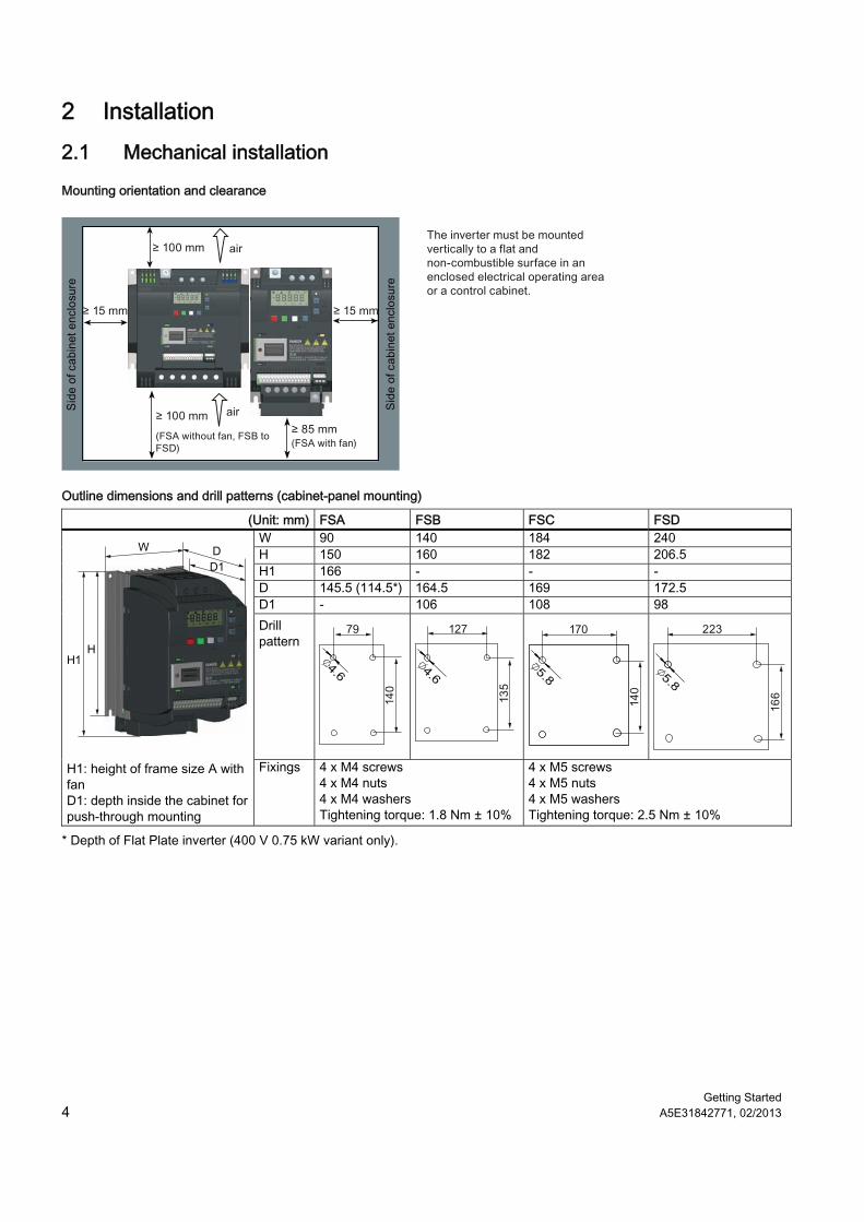
Mounting orientation and clearance
Outline dimensions and drill patterns (cabinet-panel mounting)
(Unit: mm) FSA FSB FSC FSD W 90 140 184 240 H 150 160 182 206.5 H1 166 - - - D 145.5 (114.5*) 164.5 169 172.5 D1 - 106 108 98 Drill pattern
H1: height of frame size A with fan D1: depth inside the cabinet for push-through mounting
Fixings 4 x M4 screws 4 x M4 nuts 4 x M4 washers Tightening torque: 1.8 Nm ± 10%
4 x M5 screws 4 x M5 nuts 4 x M5 washers Tightening torque: 2.5 Nm ± 10%
* Depth of Flat Plate inverter (400 V 0.75 kW variant only).
Getting Started A5E31842771, 02/2013 5
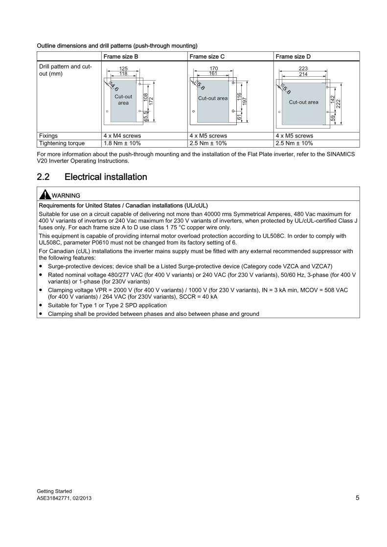
Outline dimensions and drill patterns (push-through mounting)
Frame size B Frame size C Frame size D Drill pattern and cut-out (mm)
Fixings 4 x M4 screws 4 x M5 screws 4 x M5 screws Tightening torque 1.8 Nm ± 10% 2.5 Nm ± 10% 2.5 Nm ± 10%
For more information about the push-through mounting and the installation of the Flat Plate inverter, refer to the SINAMICS V20 Inverter Operating Instructions.
2.2 Electrical installation
WARNING Requirements for United States / Canadian installations (UL/cUL) Suitable for use on a circuit capable of delivering not more than 40000 rms Symmetrical Amperes, 480 Vac maximum for 400 V variants of inverters or 240 Vac maximum for 230 V variants of inverters, when protected by UL/cUL-certified Class J fuses only. For each frame size A to D use class 1 75 °C copper wire only. This equipment is capable of providing internal motor overload protection according to UL508C. In order to comply with UL508C, parameter P0610 must not be changed from its factory setting of 6. For Canadian (cUL) installations the inverter mains supply must be fitted with any external recommended suppressor with the following features: ● Surge-protective devices; device shall be a Listed Surge-protective device (Category code VZCA and VZCA7) ● Rated nominal voltage 480/277 VAC (for 400 V variants) or 240 VAC (for 230 V variants), 50/60 Hz, 3-phase (for 400 V
variants) or 1-phase (for 230V variants) ● Clamping voltage VPR = 2000 V (for 400 V variants) / 1000 V (for 230 V variants), IN = 3 kA min, MCOV = 508 VAC
(for 400 V variants) / 264 VAC (for 230V variants), SCCR = 40 kA ● Suitable for Type 1 or Type 2 SPD application ● Clamping shall be provided between phases and also between phase and ground
Getting Started 6 A5E31842771, 02/2013
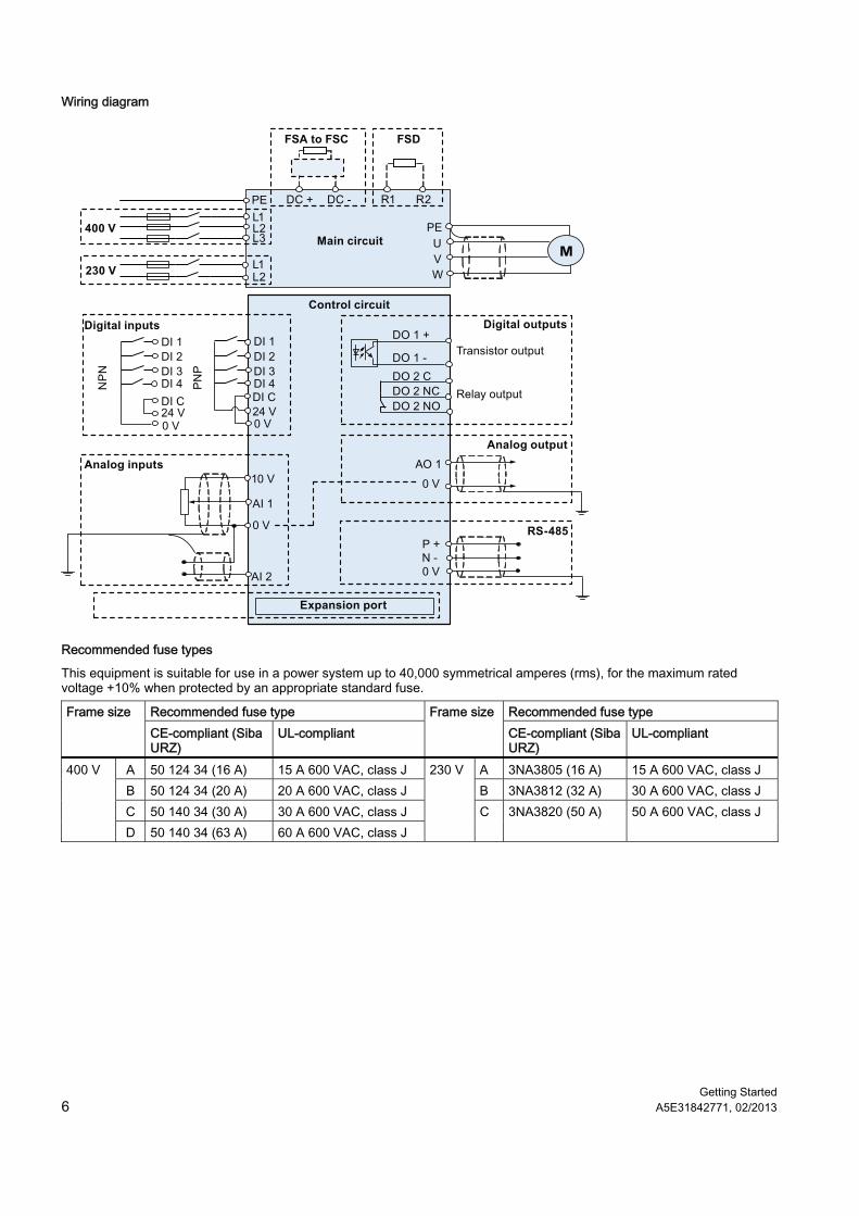
Wiring diagram
M
Digital inputs
Control circuitDigital outputs
Transistor output
Relay output
Analog inputs
Expansion port
Analog output
Main circuit
FSA to FSC
RS-485
FSD
400 V
230 V
Recommended fuse types
This equipment is suitable for use in a power system up to 40,000 symmetrical amperes (rms), for the maximum rated voltage +10% when protected by an appropriate standard fuse.
Recommended fuse type Recommended fuse type Frame size CE-compliant (Siba URZ)
UL-compliant Frame size
CE-compliant (Siba URZ)
UL-compliant
A 50 124 34 (16 A) 15 A 600 VAC, class J A 3NA3805 (16 A) 15 A 600 VAC, class J B 50 124 34 (20 A) 20 A 600 VAC, class J B 3NA3812 (32 A) 30 A 600 VAC, class J C 50 140 34 (30 A) 30 A 600 VAC, class J
400 V
D 50 140 34 (63 A) 60 A 600 VAC, class J
230 V
C 3NA3820 (50 A) 50 A 600 VAC, class J
Getting Started A5E31842771, 02/2013 7
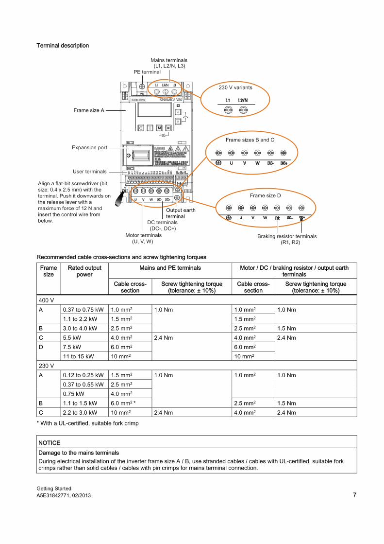
Terminal description
Recommended cable cross-sections and screw tightening torques
Mains and PE terminals Motor / DC / braking resistor / output earth terminals
Frame size
Rated output power
Cable cross-section
Screw tightening torque (tolerance: ± 10%)
Cable cross-section
Screw tightening torque (tolerance: ± 10%)
400 V 0.37 to 0.75 kW 1.0 mm2 1.0 mm2 A 1.1 to 2.2 kW 1.5 mm2 1.5 mm2
1.0 Nm
B 3.0 to 4.0 kW 2.5 mm2
1.0 Nm
2.5 mm2 1.5 Nm C 5.5 kW 4.0 mm2 4.0 mm2
7.5 kW 6.0 mm2 6.0 mm2 D 11 to 15 kW 10 mm2
2.4 Nm
10 mm2
2.4 Nm
230 V 0.12 to 0.25 kW 1.5 mm2 0.37 to 0.55 kW 2.5 mm2
A
0.75 kW 4.0 mm2
1.0 mm2 1.0 Nm
B 1.1 to 1.5 kW 6.0 mm2 *
1.0 Nm
2.5 mm2 1.5 Nm C 2.2 to 3.0 kW 10 mm2 2.4 Nm 4.0 mm2 2.4 Nm
* With a UL-certified, suitable fork crimp
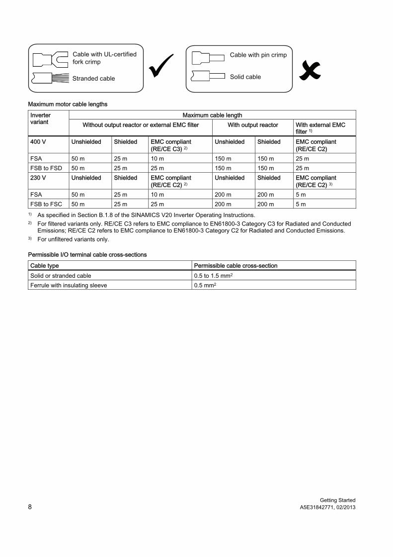
NOTICE Damage to the mains terminals During electrical installation of the inverter frame size A / B, use stranded cables / cables with UL-certified, suitable fork crimps rather than solid cables / cables with pin crimps for mains terminal connection.
Getting Started 8 A5E31842771, 02/2013
Maximum motor cable lengths
Maximum cable length Inverter variant Without output reactor or external EMC filter With output reactor With external EMC
filter 1) 400 V Unshielded Shielded EMC compliant
(RE/CE C3) 2) Unshielded Shielded EMC compliant
(RE/CE C2) FSA 50 m 25 m 10 m 150 m 150 m 25 m FSB to FSD 50 m 25 m 25 m 150 m 150 m 25 m 230 V Unshielded Shielded EMC compliant
(RE/CE C2) 2) Unshielded Shielded EMC compliant
(RE/CE C2) 3) FSA 50 m 25 m 10 m 200 m 200 m 5 m FSB to FSC 50 m 25 m 25 m 200 m 200 m 5 m
1) As specified in Section B.1.8 of the SINAMICS V20 Inverter Operating Instructions. 2) For filtered variants only. RE/CE C3 refers to EMC compliance to EN61800-3 Category C3 for Radiated and Conducted
Emissions; RE/CE C2 refers to EMC compliance to EN61800-3 Category C2 for Radiated and Conducted Emissions. 3) For unfiltered variants only.
Permissible I/O terminal cable cross-sections
Cable type Permissible cable cross-section Solid or stranded cable 0.5 to 1.5 mm2 Ferrule with insulating sleeve 0.5 mm2
Getting Started A5E31842771, 02/2013 9
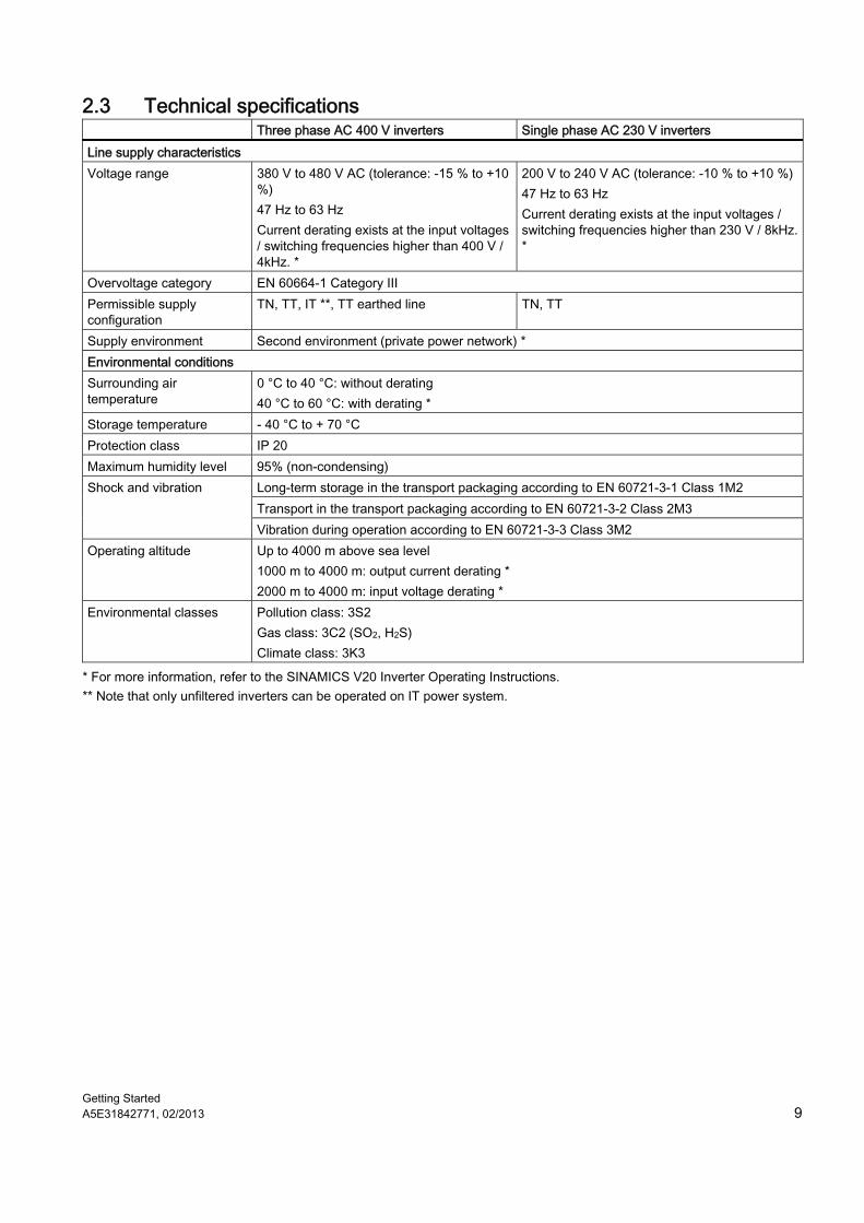
2.3 Technical specifications Three phase AC 400 V inverters Single phase AC 230 V inverters Line supply characteristics Voltage range 380 V to 480 V AC (tolerance: -15 % to +10
%) 47 Hz to 63 Hz Current derating exists at the input voltages / switching frequencies higher than 400 V / 4kHz. *
200 V to 240 V AC (tolerance: -10 % to +10 %) 47 Hz to 63 Hz Current derating exists at the input voltages / switching frequencies higher than 230 V / 8kHz. *
Overvoltage category EN 60664-1 Category III Permissible supply configuration
TN, TT, IT **, TT earthed line TN, TT
Supply environment Second environment (private power network) * Environmental conditions Surrounding air temperature
0 °C to 40 °C: without derating 40 °C to 60 °C: with derating *
Storage temperature - 40 °C to + 70 °C Protection class IP 20 Maximum humidity level 95% (non-condensing)
Long-term storage in the transport packaging according to EN 60721-3-1 Class 1M2 Transport in the transport packaging according to EN 60721-3-2 Class 2M3
Shock and vibration
Vibration during operation according to EN 60721-3-3 Class 3M2 Operating altitude Up to 4000 m above sea level
1000 m to 4000 m: output current derating * 2000 m to 4000 m: input voltage derating *
Environmental classes Pollution class: 3S2 Gas class: 3C2 (SO2, H2S) Climate class: 3K3
* For more information, refer to the SINAMICS V20 Inverter Operating Instructions. ** Note that only unfiltered inverters can be operated on IT power system.
Getting Started 10 A5E31842771, 02/2013
3 Commissioning For more information about parameters, faults, and alarms, refer to Appendix A of the English or Chinese version of this document.
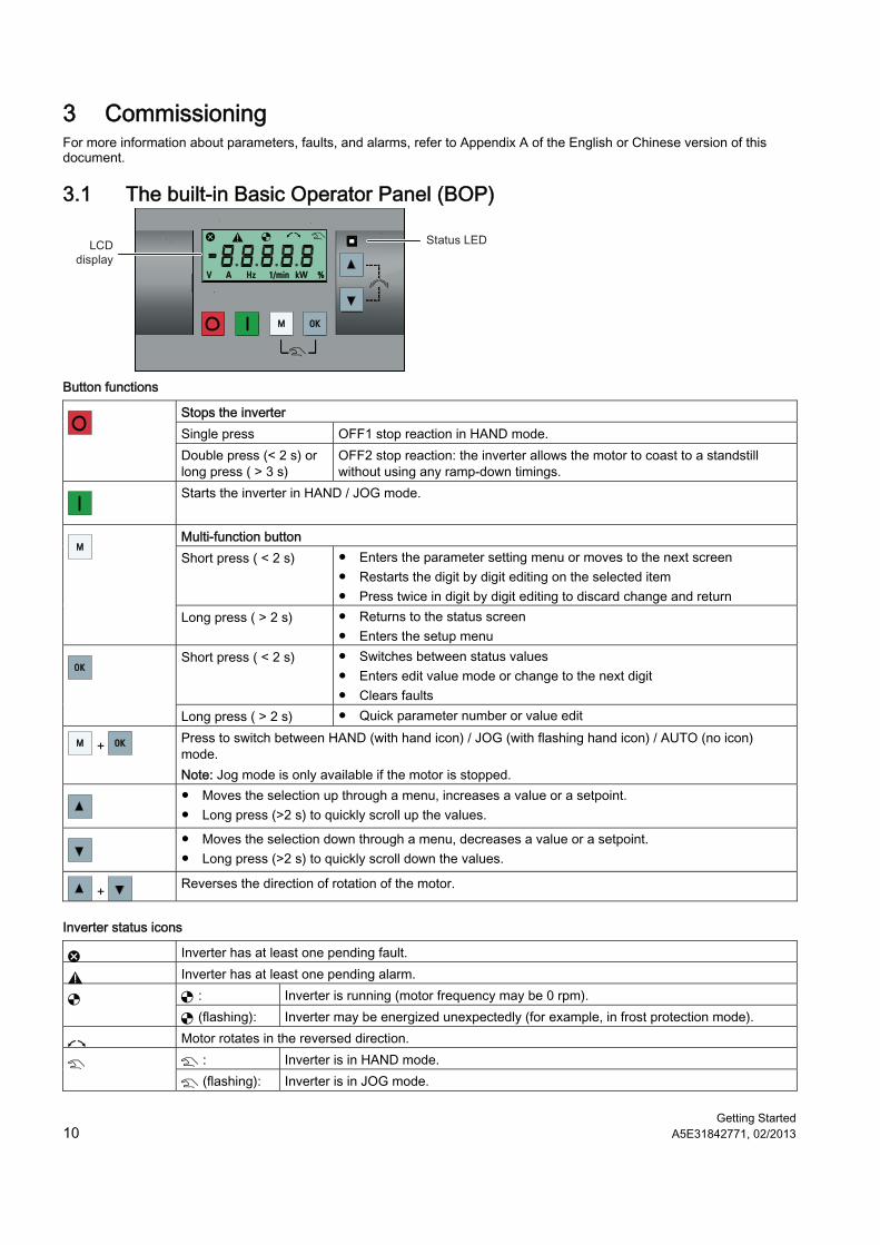
3.1 The built-in Basic Operator Panel (BOP)
OKOKMM
VV AA HzHz 1/min1/min kWkW %%
Button functions
Stops the inverter Single press OFF1 stop reaction in HAND mode.
Double press (< 2 s) or long press ( > 3 s)
OFF2 stop reaction: the inverter allows the motor to coast to a standstill without using any ramp-down timings.
Starts the inverter in HAND / JOG mode.
Multi-function button Short press ( < 2 s) ● Enters the parameter setting menu or moves to the next screen
● Restarts the digit by digit editing on the selected item ● Press twice in digit by digit editing to discard change and return
MM
Long press ( > 2 s) ● Returns to the status screen ● Enters the setup menu
Short press ( < 2 s) ● Switches between status values ● Enters edit value mode or change to the next digit ● Clears faults
OKOK
Long press ( > 2 s) ● Quick parameter number or value edit
MM + OKOK Press to switch between HAND (with hand icon) / JOG (with flashing hand icon) / AUTO (no icon) mode. Note: Jog mode is only available if the motor is stopped.
● Moves the selection up through a menu, increases a value or a setpoint. ● Long press (>2 s) to quickly scroll up the values.
● Moves the selection down through a menu, decreases a value or a setpoint. ● Long press (>2 s) to quickly scroll down the values.
+ Reverses the direction of rotation of the motor.
Inverter status icons
Inverter has at least one pending fault.
Inverter has at least one pending alarm. : Inverter is running (motor frequency may be 0 rpm). (flashing): Inverter may be energized unexpectedly (for example, in frost protection mode).
Motor rotates in the reversed direction. : Inverter is in HAND mode. (flashing): Inverter is in JOG mode.
Getting Started A5E31842771, 02/2013 11
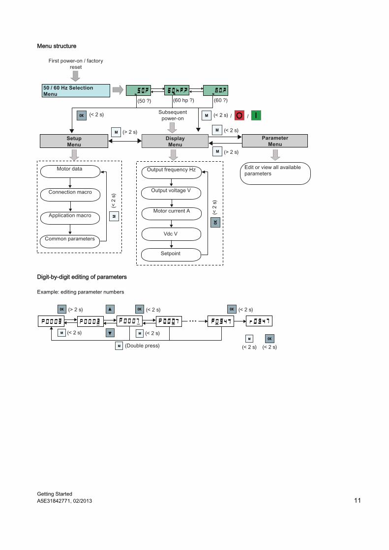
Menu structure
MM
MM
MM
MM
OKOK
OKOK
MM
HzHz HzHzHzHz
DisplayMenu
ParameterMenu
Setup Menu
50 / 60 Hz Selection Menu
Subsequent power-on
Digit-by-digit editing of parameters
MM
OKOK OKOK OKOK
OKOK
MM MM
MM
Getting Started 12 A5E31842771, 02/2013
3.2 Quick commissioning
Note This section describes how to perform the quick commissioning through the setup menu. If you are used to commissioning the inverter by setting parameters of your choice in the parameter menu, refer to the SINAMICS V20 Inverter Operating Instructions for a detailed description.
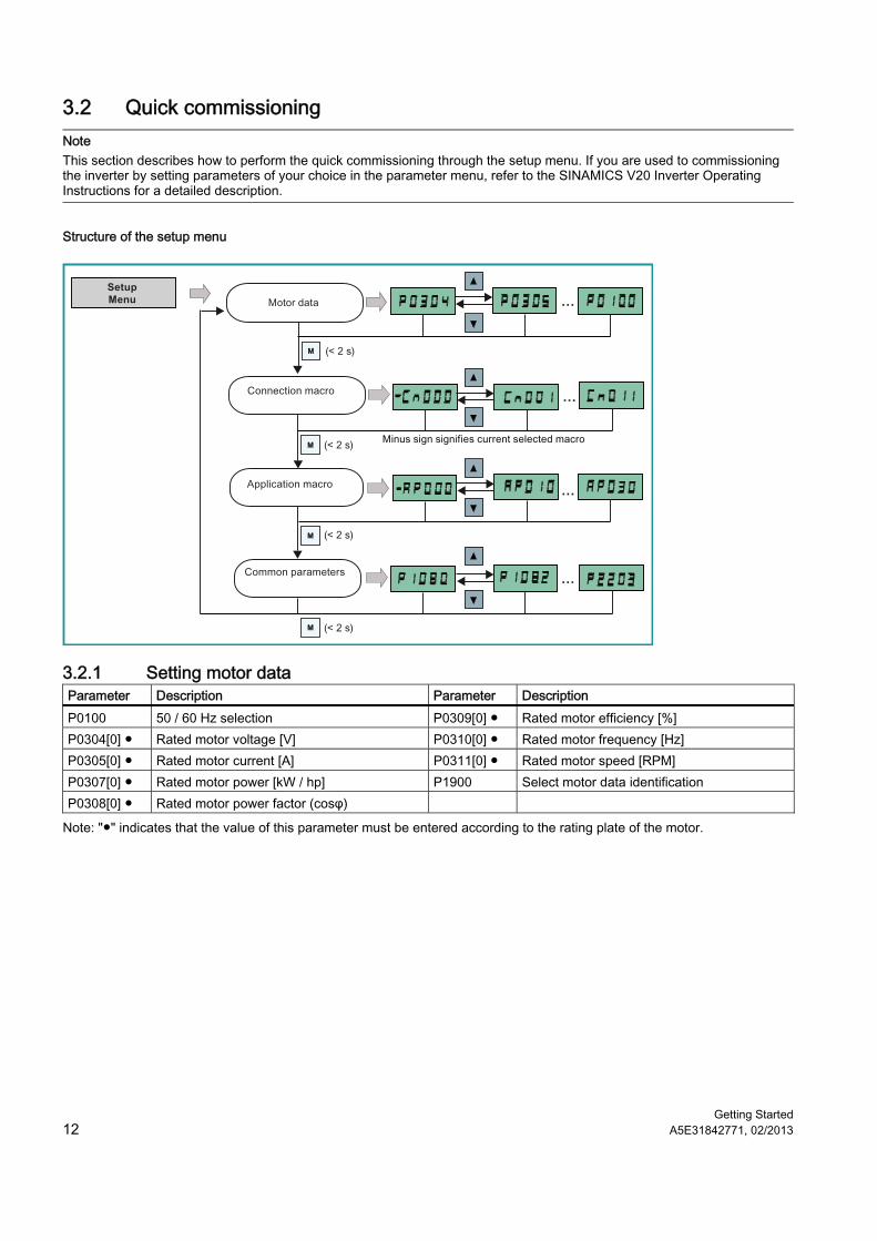
Structure of the setup menu
MM
MM
MM
MM
SetupMenu
3.2.1 Setting motor data Parameter Description Parameter Description P0100 50 / 60 Hz selection P0309[0] ● Rated motor efficiency [%] P0304[0] ● Rated motor voltage [V] P0310[0] ● Rated motor frequency [Hz] P0305[0] ● Rated motor current [A] P0311[0] ● Rated motor speed [RPM] P0307[0] ● Rated motor power [kW / hp] P1900 Select motor data identification P0308[0] ● Rated motor power factor (cosφ)
Note: "●" indicates that the value of this parameter must be entered according to the rating plate of the motor.
Getting Started A5E31842771, 02/2013 13
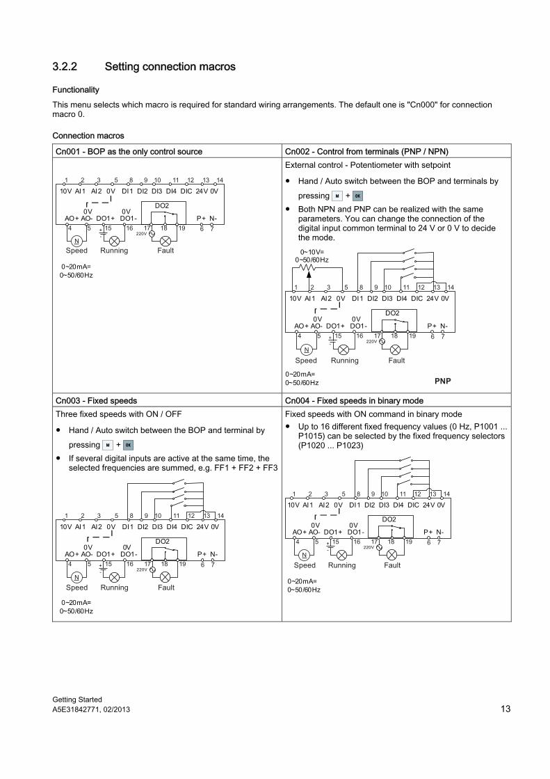
3.2.2 Setting connection macros
Functionality
This menu selects which macro is required for standard wiring arrangements. The default one is "Cn000" for connection macro 0.
Connection macros
Cn001 - BOP as the only control source Cn002 - Control from terminals (PNP / NPN)
10V AI1 AI2 0V DI1 DI2 DI3 DI4 DIC 24V 0V
AO+ AO- DO1+ DO1- P+ N-
DO20V 0V
0~20mA=0~50/60Hz
220V
N
External control - Potentiometer with setpoint
● Hand / Auto switch between the BOP and terminals by pressing MM + OKOK
● Both NPN and PNP can be realized with the same parameters. You can change the connection of the digital input common terminal to 24 V or 0 V to decide the mode. 0~10V=
0~50/60Hz
10V AI1 AI2 0V DI1 DI2 DI3 DI4 DIC 24V 0V
AO+ AO- DO1+ DO1- P+ N-
DO20V 0V
0~20mA=0~50/60Hz
220V
N
PNP
Cn003 - Fixed speeds Cn004 - Fixed speeds in binary mode Three fixed speeds with ON / OFF
● Hand / Auto switch between the BOP and terminal by pressing MM + OKOK
● If several digital inputs are active at the same time, the selected frequencies are summed, e.g. FF1 + FF2 + FF3
10V AI1 AI2 0V DI1 DI2 DI3 DI4 DIC 24V 0V
AO+ AO- DO1+ DO1- P+ N-
DO20V 0V
0~20mA=0~50/60Hz
220V
N
Fixed speeds with ON command in binary mode ● Up to 16 different fixed frequency values (0 Hz, P1001 ...
P1015) can be selected by the fixed frequency selectors (P1020 ... P1023)
10V AI1 AI2 0V DI1 DI2 DI3 DI4 DIC 24V 0V
AO+ AO- DO1+ DO1- P+ N-
DO20V 0V
0~20mA=0~50/60Hz
220V
N
Getting Started 14 A5E31842771, 02/2013
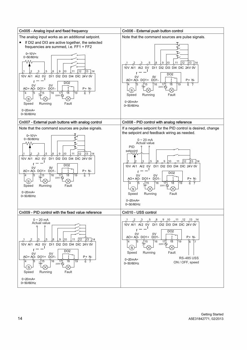
Cn005 - Analog input and fixed frequency Cn006 - External push button control The analog input works as an additional setpoint. ● If DI2 and DI3 are active together, the selected
frequencies are summed, i.e. FF1 + FF2
10V AI1 AI2 0V DI1 DI2 DI3 DI4 DIC 24V 0V
AO+ AO- DO1+ DO1- P+ N-
DO20V 0V
0~20mA=0~50/60Hz
220V
0~10V= 0~50/60Hz
N
Note that the command sources are pulse signals.
10V AI1 AI2 0V DI1 DI2 DI3 DI4 DIC 24V 0V
AO+ AO- DO1+ DO1- P+ N-
DO20V 0V
0~20mA=0~50/60Hz
220V
N
Cn007 - External push buttons with analog control Cn008 - PID control with analog reference Note that the command sources are pulse signals.
10V AI1 AI2 0V DI1 DI2 DI3 DI4 DIC 24V 0V
AO+ AO- DO1+ DO1- P+ N-
DO20V 0V
0~20mA=0~50/60Hz
220V
0~10V= 0~50/60Hz
N
If a negative setpoint for the PID control is desired, change the setpoint and feedback wiring as needed.
10V AI1 AI2 0V DI1 DI2 DI3 DI4 DIC 24V 0V
AO+ AO- DO1+ DO1- P+ N-
DO20V 0V
0~20mA=0~50/60Hz
220V
N
Cn009 - PID control with the fixed value reference Cn010 - USS control
10V AI1 AI2 0V DI1 DI2 DI3 DI4 DIC 24V 0V
AO+ AO- DO1+ DO1- P+ N-
DO20V 0V
0~20mA=0~50/60Hz
220V
N
10V AI1 AI2 0V DI1 DI2 DI3 DI4 DIC 24V 0V
AO+ AO- DO1+ DO1- P+ N-
DO20V 0V
0~20mA=0~50/60Hz
220V
N
Getting Started A5E31842771, 02/2013 15
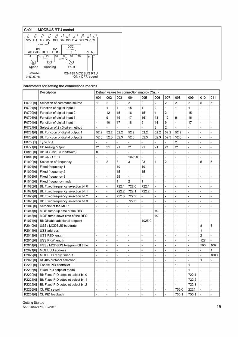
Cn011 - MODBUS RTU control
10V AI1 AI2 0V DI1 DI2 DI3 DI4 DIC 24V 0V
AO+ AO- DO1+ DO1- P+ N-
DO20V 0V
0~20mA=0~50/60Hz
220V
N
Parameters for setting the connections macros Default values for connection macros (Cn...) Description 001 002 003 004 005 006 007 008 009 010 011
P0700[0] Selection of command source 1 2 2 2 2 2 2 2 2 5 5 P0701[0] Function of digital input 1 - 1 1 15 1 2 1 1 1 - - P0702[0] Function of digital input 2 - 12 15 16 15 1 2 - 15 - - P0703[0] Function of digital input 3 - 9 16 17 16 13 12 9 16 - - P0704[0] Function of digital input 4 - 10 17 18 9 14 9 - 17 - - P0727[0] Selection of 2 / 3-wire method - - - - - 3 2 - - - - P0731[0] BI: Function of digital output 1 52.2 52.2 52.2 52.2 52.2 52.2 52.2 52.2 - - - P0732[0] BI: Function of digital output 2 52.3 52.3 52.3 52.3 52.3 52.3 52.3 52.3 - - - P0756[1] Type of AI - - - - - - - 2 - - - P0771[0] CI: Analog output 21 21 21 21 21 21 21 21 - - - P0810[0] BI: CDS bit 0 (Hand/Auto) 0 - - - - - - - - - - P0840[0] BI: ON / OFF1 - - - 1025.0 - - - - - - - P1000[0] Selection of frequency 1 2 3 3 23 1 2 - - 5 5 P1001[0] Fixed frequency 1 - - 10 - 10 - - - - - - P1002[0] Fixed frequency 2 - - 15 - 15 - - - - - - P1003[0] Fixed frequency 3 - - 25 - - - - - - - - P1016[0] Fixed frequency mode - - 1 2 1 - - - - - - P1020[0] BI: Fixed frequency selection bit 0 - - 722.1 722.0 722.1 - - - - - - P1021[0] BI: Fixed frequency selection bit 1 - - 722.2 722.1 722.2 - - - - - - P1022[0] BI: Fixed frequency selection bit 2 - - 722.3 722.2 - - - - - - - P1023[0] BI: Fixed frequency selection bit 3 - - - 722.3 - - - - - - - P1040[0] Setpoint of the MOP - - - - - 0 - - - - - P1047[0] MOP ramp-up time of the RFG - - - - - 10 - - - - - P1048[0] MOP ramp-down time of the RFG - - - - - 10 - - - - - P1074[0] BI: Disable additional setpoint - - - - 1025.0 - - - - - - P2010[0] USS / MODBUS baudrate - - - - - - - - - 8 6 P2011[0] USS address - - - - - - - - - 1 - P2012[0] USS PZD length - - - - - - - - - 2 - P2013[0] USS PKW length - - - - - - - - - 127 - P2014[0] USS / MODBUS telegram off time - - - - - - - - - 500 100 P2021[0] MODBUS address - - - - - - - - - - 1 P2022[0] MODBUS reply timeout - - - - - - - - - - 1000P2023[0] RS485 protocol selection - - - - - - - - - 1 2 P2200[0] Enable PID controller - - - - - - - 1 1 - - P2216[0] Fixed PID setpoint mode - - - - - - - - 1 - - P2220[0] BI: Fixed PID setpoint select bit 0 - - - - - - - - 722.1 - - P2221[0] BI: Fixed PID setpoint select bit 1 - - - - - - - - 722.2 - - P2222[0] BI: Fixed PID setpoint select bit 2 - - - - - - - - 722.3 - - P2253[0] CI: PID setpoint - - - - - - - 755.0 2224 - - P2264[0] CI: PID feedback - - - - - - - 755.1 755.1 - -
Getting Started 16 A5E31842771, 02/2013
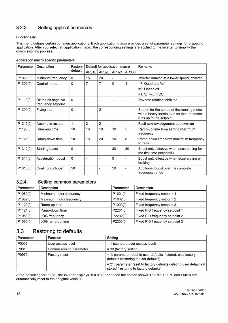
3.2.3 Setting application macros
Functionality
This menu defines certain common applications. Each application macro provides a set of parameter settings for a specific application. After you select an application macro, the corresponding settings are applied to the inverter to simplify the commissioning process.
Application macro specific parameters
Default for application macro Parameter Description Factory default AP010 AP020 AP021 AP030
Remarks
P1080[0] Minimum frequency 0 15 20 - - Inverter running at a lower speed inhibited P1300[0] Control mode 0 7 7 0 1 =7: Quadratic V/f
=0: Linear V/f =1: V/f with FCC
P1110[0] BI: Inhibit negative frequency setpoint
0 1 - - - Reverse rotation inhibited
P1200[0] Flying start 0 - 2 - - Search for the speed of the running motor with a heavy inertia load so that the motor runs up to the setpoint
P1210[0] Automatic restart 1 2 2 - - Fault acknowledgement at power-on P1120[0] Ramp-up time 10 10 10 10 5 Ramp-up time from zero to maximum
frequency P1121[0] Ramp-down time 10 10 20 10 5 Ramp-down time from maximum frequency
to zero P1312[0] Starting boost 0 - - 30 30 Boost only effective when accelerating for
the first time (standstill) P1311[0] Acceleration boost 0 - - 0 - Boost only effective when accelerating or
braking P1310[0] Continuous boost 50 - 50 - Additional boost over the complete
frequency range
3.2.4 Setting common parameters Parameter Description Parameter Description P1080[0] Minimum motor frequency P1001[0] Fixed frequency setpoint 1 P1082[0] Maximum motor frequency P1002[0] Fixed frequency setpoint 2 P1120[0] Ramp-up time P1003[0] Fixed frequency setpoint 3 P1121[0] Ramp-down time P2201[0] Fixed PID frequency setpoint 1 P1058[0] JOG frequency P2202[0] Fixed PID frequency setpoint 2 P1060[0] JOG ramp-up time P2203[0] Fixed PID frequency setpoint 3
3.3 Restoring to defaults Parameter Function Setting P0003 User access level = 1 (standard user access level) P0010 Commissioning parameter = 30 (factory setting) P0970 Factory reset = 1: parameter reset to user defaults if stored, else factory
defaults (restoring to user defaults) = 21: parameter reset to factory defaults deleting user defaults if stored (restoring to factory defaults)
After the setting for P0970, the inverter displays "8 8 8 8 8" and then the screen shows "P0970". P0970 and P0010 are automatically reset to their original value 0.
Getting Started A5E31842771, 02/2013 17
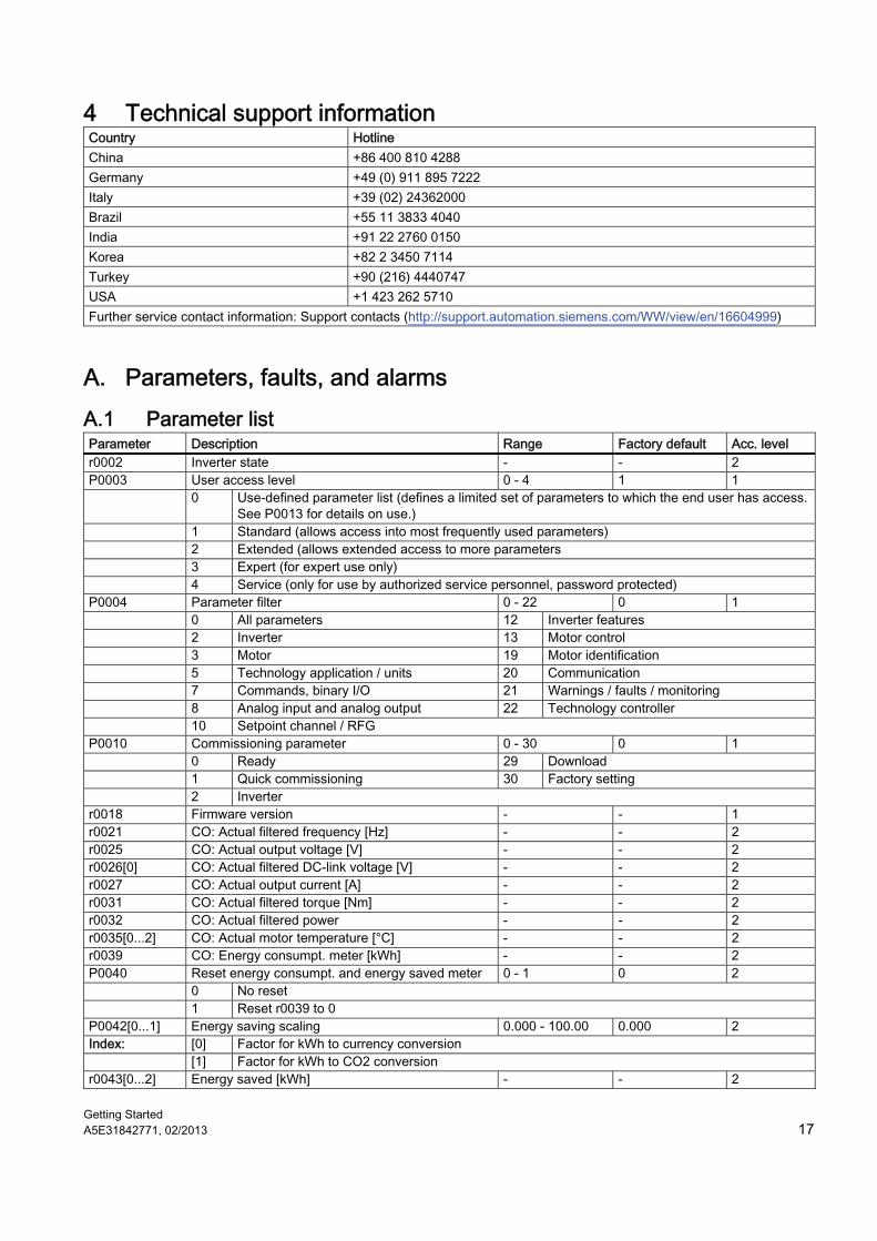
4 Technical support information Country Hotline China +86 400 810 4288 Germany +49 (0) 911 895 7222 Italy +39 (02) 24362000 Brazil +55 11 3833 4040 India +91 22 2760 0150 Korea +82 2 3450 7114 Turkey +90 (216) 4440747 USA +1 423 262 5710 Further service contact information: Support contacts (http://support.automation.siemens.com/WW/view/en/16604999)
A. Parameters, faults, and alarms A.1 Parameter list Parameter Description Range Factory default Acc. level r0002 Inverter state - - 2 P0003 User access level 0 - 4 1 1 0 Use-defined parameter list (defines a limited set of parameters to which the end user has access.
See P0013 for details on use.) 1 Standard (allows access into most frequently used parameters) 2 Extended (allows extended access to more parameters 3 Expert (for expert use only) 4 Service (only for use by authorized service personnel, password protected) P0004 Parameter filter 0 - 22 0 1 0 All parameters 12 Inverter features 2 Inverter 13 Motor control 3 Motor 19 Motor identification 5 Technology application / units 20 Communication 7 Commands, binary I/O 21 Warnings / faults / monitoring 8 Analog input and analog output 22 Technology controller 10 Setpoint channel / RFG P0010 Commissioning parameter 0 - 30 0 1 0 Ready 29 Download 1 Quick commissioning 30 Factory setting 2 Inverter r0018 Firmware version - - 1 r0021 CO: Actual filtered frequency [Hz] - - 2 r0025 CO: Actual output voltage [V] - - 2 r0026[0] CO: Actual filtered DC-link voltage [V] - - 2 r0027 CO: Actual output current [A] - - 2 r0031 CO: Actual filtered torque [Nm] - - 2 r0032 CO: Actual filtered power - - 2 r0035[0...2] CO: Actual motor temperature [°C] - - 2 r0039 CO: Energy consumpt. meter [kWh] - - 2 P0040 Reset energy consumpt. and energy saved meter 0 - 1 0 2 0 No reset 1 Reset r0039 to 0 P0042[0...1] Energy saving scaling 0.000 - 100.00 0.000 2 Index: [0] Factor for kWh to currency conversion [1] Factor for kWh to CO2 conversion r0043[0...2] Energy saved [kWh] - - 2
Getting Started 18 A5E31842771, 02/2013
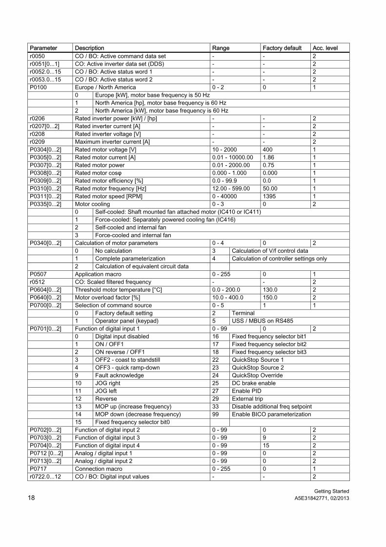
Parameter Description Range Factory default Acc. level r0050 CO / BO: Active command data set - - 2 r0051[0...1] CO: Active inverter data set (DDS) - - 2 r0052.0...15 CO / BO: Active status word 1 - - 2 r0053.0...15 CO / BO: Active status word 2 - - 2 P0100 Europe / North America 0 - 2 0 1 0 Europe [kW], motor base frequency is 50 Hz 1 North America [hp], motor base frequency is 60 Hz 2 North America [kW], motor base frequency is 60 Hz r0206 Rated inverter power [kW] / [hp] - - 2 r0207[0...2] Rated inverter current [A] - - 2 r0208 Rated inverter voltage [V] - - 2 r0209 Maximum inverter current [A] - - 2 P0304[0...2] Rated motor voltage [V] 10 - 2000 400 1 P0305[0...2] Rated motor current [A] 0.01 - 10000.00 1.86 1 P0307[0...2] Rated motor power 0.01 - 2000.00 0.75 1 P0308[0...2] Rated motor cosφ 0.000 - 1.000 0.000 1 P0309[0...2] Rated motor efficiency [%] 0.0 - 99.9 0.0 1 P0310[0...2] Rated motor frequency [Hz] 12.00 - 599.00 50.00 1 P0311[0...2] Rated motor speed [RPM] 0 - 40000 1395 1 P0335[0...2] Motor cooling 0 - 3 0 2 0 Self-cooled: Shaft mounted fan attached motor (IC410 or IC411) 1 Force-cooled: Separately powered cooling fan (IC416) 2 Self-cooled and internal fan 3 Force-cooled and internal fan P0340[0...2] Calculation of motor parameters 0 - 4 0 2 0 No calculation 3 Calculation of V/f control data 1 Complete parameterization 4 Calculation of controller settings only 2 Calculation of equivalent circuit data P0507 Application macro 0 - 255 0 1 r0512 CO: Scaled filtered frequency - - 2 P0604[0...2] Threshold motor temperature [°C] 0.0 - 200.0 130.0 2 P0640[0...2] Motor overload factor [%] 10.0 - 400.0 150.0 2 P0700[0...2] Selection of command source 0 - 5 1 1 0 Factory default setting 2 Terminal 1 Operator panel (keypad) 5 USS / MBUS on RS485 P0701[0...2] Function of digital input 1 0 - 99 0 2 0 Digital input disabled 16 Fixed frequency selector bit1 1 ON / OFF1 17 Fixed frequency selector bit2 2 ON reverse / OFF1 18 Fixed frequency selector bit3 3 OFF2 - coast to standstill 22 QuickStop Source 1 4 OFF3 - quick ramp-down 23 QuickStop Source 2 9 Fault acknowledge 24 QuickStop Override 10 JOG right 25 DC brake enable 11 JOG left 27 Enable PID 12 Reverse 29 External trip 13 MOP up (increase frequency) 33 Disable additional freq setpoint 14 MOP down (decrease frequency) 99 Enable BICO parameterization 15 Fixed frequency selector bit0 P0702[0...2] Function of digital input 2 0 - 99 0 2 P0703[0...2] Function of digital input 3 0 - 99 9 2 P0704[0...2] Function of digital input 4 0 - 99 15 2 P0712 [0...2] Analog / digital input 1 0 - 99 0 2 P0713[0...2] Analog / digital input 2 0 - 99 0 2 P0717 Connection macro 0 - 255 0 1 r0722.0...12 CO / BO: Digital input values - - 2
Getting Started A5E31842771, 02/2013 19
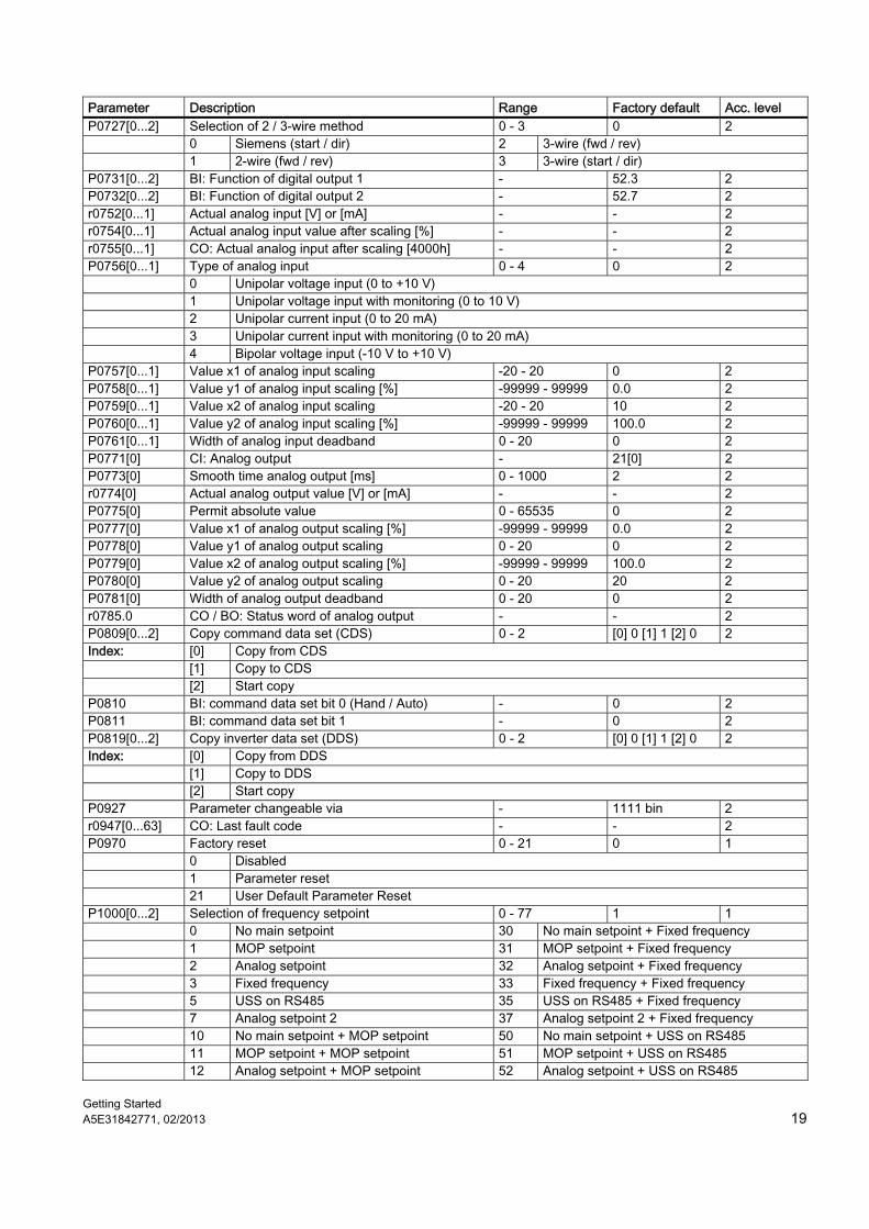
Parameter Description Range Factory default Acc. level P0727[0...2] Selection of 2 / 3-wire method 0 - 3 0 2 0 Siemens (start / dir) 2 3-wire (fwd / rev) 1 2-wire (fwd / rev) 3 3-wire (start / dir) P0731[0...2] BI: Function of digital output 1 - 52.3 2 P0732[0...2] BI: Function of digital output 2 - 52.7 2 r0752[0...1] Actual analog input [V] or [mA] - - 2 r0754[0...1] Actual analog input value after scaling [%] - - 2 r0755[0...1] CO: Actual analog input after scaling [4000h] - - 2 P0756[0...1] Type of analog input 0 - 4 0 2 0 Unipolar voltage input (0 to +10 V) 1 Unipolar voltage input with monitoring (0 to 10 V) 2 Unipolar current input (0 to 20 mA) 3 Unipolar current input with monitoring (0 to 20 mA) 4 Bipolar voltage input (-10 V to +10 V) P0757[0...1] Value x1 of analog input scaling -20 - 20 0 2 P0758[0...1] Value y1 of analog input scaling [%] -99999 - 99999 0.0 2 P0759[0...1] Value x2 of analog input scaling -20 - 20 10 2 P0760[0...1] Value y2 of analog input scaling [%] -99999 - 99999 100.0 2 P0761[0...1] Width of analog input deadband 0 - 20 0 2 P0771[0] CI: Analog output - 21[0] 2 P0773[0] Smooth time analog output [ms] 0 - 1000 2 2 r0774[0] Actual analog output value [V] or [mA] - - 2 P0775[0] Permit absolute value 0 - 65535 0 2 P0777[0] Value x1 of analog output scaling [%] -99999 - 99999 0.0 2 P0778[0] Value y1 of analog output scaling 0 - 20 0 2 P0779[0] Value x2 of analog output scaling [%] -99999 - 99999 100.0 2 P0780[0] Value y2 of analog output scaling 0 - 20 20 2 P0781[0] Width of analog output deadband 0 - 20 0 2 r0785.0 CO / BO: Status word of analog output - - 2 P0809[0...2] Copy command data set (CDS) 0 - 2 [0] 0 [1] 1 [2] 0 2 Index: [0] Copy from CDS [1] Copy to CDS [2] Start copy P0810 BI: command data set bit 0 (Hand / Auto) - 0 2 P0811 BI: command data set bit 1 - 0 2 P0819[0...2] Copy inverter data set (DDS) 0 - 2 [0] 0 [1] 1 [2] 0 2 Index: [0] Copy from DDS [1] Copy to DDS [2] Start copy P0927 Parameter changeable via - 1111 bin 2 r0947[0...63] CO: Last fault code - - 2 P0970 Factory reset 0 - 21 0 1 0 Disabled 1 Parameter reset 21 User Default Parameter Reset P1000[0...2] Selection of frequency setpoint 0 - 77 1 1 0 No main setpoint 30 No main setpoint + Fixed frequency 1 MOP setpoint 31 MOP setpoint + Fixed frequency 2 Analog setpoint 32 Analog setpoint + Fixed frequency 3 Fixed frequency 33 Fixed frequency + Fixed frequency 5 USS on RS485 35 USS on RS485 + Fixed frequency 7 Analog setpoint 2 37 Analog setpoint 2 + Fixed frequency 10 No main setpoint + MOP setpoint 50 No main setpoint + USS on RS485 11 MOP setpoint + MOP setpoint 51 MOP setpoint + USS on RS485 12 Analog setpoint + MOP setpoint 52 Analog setpoint + USS on RS485
Getting Started 20 A5E31842771, 02/2013
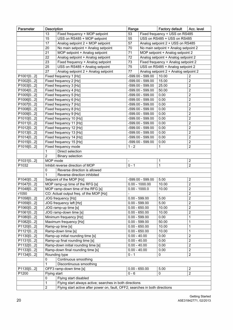
Parameter Description Range Factory default Acc. level 13 Fixed frequency + MOP setpoint 53 Fixed frequency + USS on RS485 15 USS on RS485 + MOP setpoint 55 USS on RS485 + USS on RS485 17 Analog setpoint 2 + MOP setpoint 57 Analog setpoint 2 + USS on RS485 20 No main setpoint + Analog setpoint 70 No main setpoint + Analog setpoint 2 21 MOP setpoint + Analog setpoint 71 MOP setpoint + Analog setpoint 2 22 Analog setpoint + Analog setpoint 72 Analog setpoint + Analog setpoint 2 23 Fixed frequency + Analog setpoint 73 Fixed frequency + Analog setpoint 2 25 USS on RS485 + Analog setpoint 75 USS on RS485 + Analog setpoint 2 27 Analog setpoint 2 + Analog setpoint 77 Analog setpoint 2 + Analog setpoint 2 P1001[0...2] Fixed frequency 1 [Hz] -599.00 - 599.00 10.00 2 P1002[0...2] Fixed frequency 2 [Hz] -599.00 - 599.00 15.00 2 P1003[0...2] Fixed frequency 3 [Hz] -599.00 - 599.00 25.00 2 P1004[0...2] Fixed frequency 4 [Hz] -599.00 - 599.00 50.00 2 P1005[0...2] Fixed frequency 5 [Hz] -599.00 - 599.00 0.00 2 P1006[0...2] Fixed frequency 6 [Hz] -599.00 - 599.00 0.00 2 P1007[0...2] Fixed frequency 7 [Hz] -599.00 - 599.00 0.00 2 P1008[0...2] Fixed frequency 8 [Hz] -599.00 - 599.00 0.00 2 P1009[0...2] Fixed frequency 9 [Hz] -599.00 - 599.00 0.00 2 P1010[0...2] Fixed frequency 10 [Hz] -599.00 - 599.00 0.00 2 P1011[0...2] Fixed frequency 11 [Hz] -599.00 - 599.00 0.00 2 P1012[0...2] Fixed frequency 12 [Hz] -599.00 - 599.00 0.00 2 P1013[0...2] Fixed frequency 13 [Hz] -599.00 - 599.00 0.00 2 P1014[0...2] Fixed frequency 14 [Hz] -599.00 - 599.00 0.00 2 P1015[0...2] Fixed frequency 15 [Hz] -599.00 - 599.00 0.00 2 P1016[0...2] Fixed frequency mode 1 - 2 1 2 1 Direct selection 2 Binary selection P1031[0...2] MOP mode - 1 2 P1032 Inhibit reverse direction of MOP 0 - 1 1 2 0 Reverse direction is allowed 1 Reverse direction inhibited P1040[0...2] Setpoint of the MOP [Hz] -599.00 - 599.00 5.00 2 P1047[0...2] MOP ramp-up time of the RFG [s] 0.00 - 1000.00 10.00 2 P1048[0...2] MOP ramp-down time of the RFG [s] 0.00 - 1000.0 10.00 2 r1050 CO: Actual output freq. of the MOP [Hz] - - 2 P1058[0...2] JOG frequency [Hz] 0.00 - 599.00 5.00 2 P1059[0...2] JOG frequency left [Hz] 0.00 - 599.00 5.00 2 P1060[0...2] JOG ramp-up time [s] 0.00 - 650.00 10.00 2 P1061[0...2] JOG ramp-down time [s] 0.00 - 650.00 10.00 2 P1080[0...2] Minimum frequency [Hz] 0.00 - 599.00 0.00 1 P1082[0...2] Maximum frequency [Hz] 0.00 - 599.00 50.00 1 P1120[0...2] Ramp-up time [s] 0.00 - 650.00 10.00 1 P1121[0...2] Ramp-down time [s] 0.00 - 650.00 10.00 1 P1130[0...2] Ramp-up initial rounding time [s] 0.00 - 40.00 0.00 2 P1131[0...2] Ramp-up final rounding time [s] 0.00 - 40.00 0.00 2 P1132[0...2] Ramp-down initial rounding time [s] 0.00 - 40.00 0.00 2 P1133[0...2] Ramp-down final rounding time [s] 0.00 - 40.00 0.00 2 P1134[0...2] Rounding type 0 - 1 0 2 0 Continuous smoothing 1 Discontinuous smoothing P1135[0...2] OFF3 ramp-down time [s] 0.00 - 650.00 5.00 2 P1200 Flying start 0 - 6 0 2 0 Flying start disabled 1 Flying start always active; searches in both directions 2 Flying start active after power on, fault, OFF2; searches in both directions
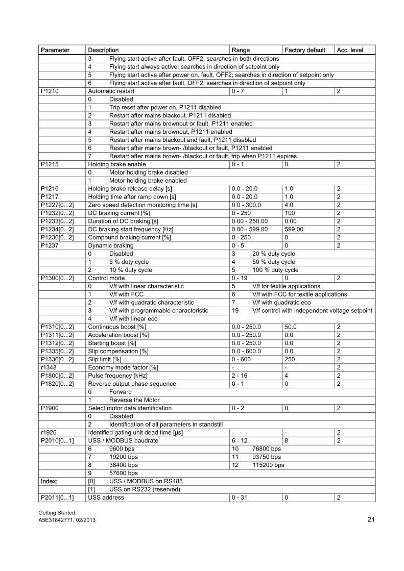
Getting Started A5E31842771, 02/2013 21
Parameter Description Range Factory default Acc. level 3 Flying start active after fault, OFF2; searches in both directions 4 Flying start always active; searches in direction of setpoint only 5 Flying start active after power on, fault, OFF2; searches in direction of setpoint only 6 Flying start active after fault, OFF2; searches in direction of setpoint only P1210 Automatic restart 0 - 7 1 2 0 Disabled 1 Trip reset after power on, P1211 disabled 2 Restart after mains blackout, P1211 disabled 3 Restart after mains brownout or fault, P1211 enabled 4 Restart after mains brownout, P1211 enabled 5 Restart after mains blackout and fault, P1211 disabled 6 Restart after mains brown- /blackout or fault, P1211 enabled 7 Restart after mains brown- /blackout or fault, trip when P1211 expires P1215 Holding brake enable 0 - 1 0 2 0 Motor holding brake disabled 1 Motor holding brake enabled P1216 Holding brake release delay [s] 0.0 - 20.0 1.0 2 P1217 Holding time after ramp down [s] 0.0 - 20.0 1.0 2 P1227[0...2] Zero speed detection monitoring time [s] 0.0 - 300.0 4.0 2 P1232[0...2] DC braking current [%] 0 - 250 100 2 P1233[0...2] Duration of DC braking [s] 0.00 - 250.00 0.00 2 P1234[0...2] DC braking start frequency [Hz] 0.00 - 599.00 599.00 2 P1236[0...2] Compound braking current [%] 0 - 250 0 2 P1237 Dynamic braking 0 - 5 0 2 0 Disabled 3 20 % duty cycle 1 5 % duty cycle 4 50 % duty cycle 2 10 % duty cycle 5 100 % duty cycle P1300[0...2] Control mode 0 - 19 0 2 0 V/f with linear characteristic 5 V/f for textile applications 1 V/f with FCC 6 V/f with FCC for textile applications 2 V/f with quadratic characteristic 7 V/f with quadratic eco 3 V/f with programmable characteristic 4 V/f with linear eco
19 V/f control with independent voltage setpoint
P1310[0...2] Continuous boost [%] 0.0 - 250.0 50.0 2 P1311[0...2] Acceleration boost [%] 0.0 - 250.0 0.0 2 P1312[0...2] Starting boost [%] 0.0 - 250.0 0.0 2 P1335[0...2] Slip compensation [%] 0.0 - 600.0 0.0 2 P1336[0...2] Slip limit [%] 0 - 600 250 2 r1348 Economy mode factor [%] - - 2 P1800[0...2] Pulse frequency [kHz] 2 - 16 4 2 P1820[0...2] Reverse output phase sequence 0 - 1 0 2 0 Forward 1 Reverse the Motor P1900 Select motor data identification 0 - 2 0 2 0 Disabled 2 Identification of all parameters in standstill r1926 Identified gating unit dead time [μs] - - 2 P2010[0...1] USS / MODBUS baudrate 6 - 12 8 2 6 9600 bps 10 76800 bps 7 19200 bps 11 93750 bps 8 38400 bps 12 115200 bps 9 57600 bps Index: [0] USS / MODBUS on RS485 [1] USS on RS232 (reserved) P2011[0...1] USS address 0 - 31 0 2
Getting Started 22 A5E31842771, 02/2013
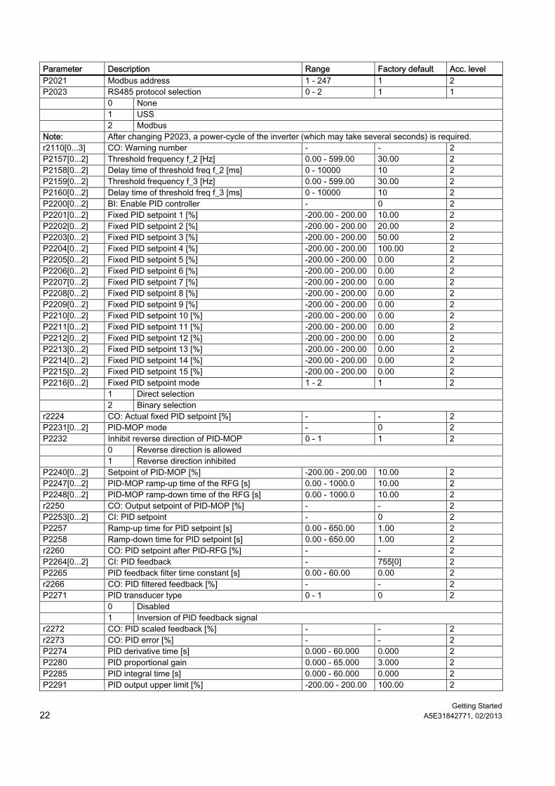
Parameter Description Range Factory default Acc. level P2021 Modbus address 1 - 247 1 2 P2023 RS485 protocol selection 0 - 2 1 1 0 None 1 USS 2 Modbus Note: After changing P2023, a power-cycle of the inverter (which may take several seconds) is required. r2110[0...3] CO: Warning number - - 2 P2157[0...2] Threshold frequency f_2 [Hz] 0.00 - 599.00 30.00 2 P2158[0...2] Delay time of threshold freq f_2 [ms] 0 - 10000 10 2 P2159[0...2] Threshold frequency f_3 [Hz] 0.00 - 599.00 30.00 2 P2160[0...2] Delay time of threshold freq f_3 [ms] 0 - 10000 10 2 P2200[0...2] BI: Enable PID controller - 0 2 P2201[0...2] Fixed PID setpoint 1 [%] -200.00 - 200.00 10.00 2 P2202[0...2] Fixed PID setpoint 2 [%] -200.00 - 200.00 20.00 2 P2203[0...2] Fixed PID setpoint 3 [%] -200.00 - 200.00 50.00 2 P2204[0...2] Fixed PID setpoint 4 [%] -200.00 - 200.00 100.00 2 P2205[0...2] Fixed PID setpoint 5 [%] -200.00 - 200.00 0.00 2 P2206[0...2] Fixed PID setpoint 6 [%] -200.00 - 200.00 0.00 2 P2207[0...2] Fixed PID setpoint 7 [%] -200.00 - 200.00 0.00 2 P2208[0...2] Fixed PID setpoint 8 [%] -200.00 - 200.00 0.00 2 P2209[0...2] Fixed PID setpoint 9 [%] -200.00 - 200.00 0.00 2 P2210[0...2] Fixed PID setpoint 10 [%] -200.00 - 200.00 0.00 2 P2211[0...2] Fixed PID setpoint 11 [%] -200.00 - 200.00 0.00 2 P2212[0...2] Fixed PID setpoint 12 [%] -200.00 - 200.00 0.00 2 P2213[0...2] Fixed PID setpoint 13 [%] -200.00 - 200.00 0.00 2 P2214[0...2] Fixed PID setpoint 14 [%] -200.00 - 200.00 0.00 2 P2215[0...2] Fixed PID setpoint 15 [%] -200.00 - 200.00 0.00 2 P2216[0...2] Fixed PID setpoint mode 1 - 2 1 2 1 Direct selection 2 Binary selection r2224 CO: Actual fixed PID setpoint [%] - - 2 P2231[0...2] PID-MOP mode - 0 2 P2232 Inhibit reverse direction of PID-MOP 0 - 1 1 2 0 Reverse direction is allowed 1 Reverse direction inhibited P2240[0...2] Setpoint of PID-MOP [%] -200.00 - 200.00 10.00 2 P2247[0...2] PID-MOP ramp-up time of the RFG [s] 0.00 - 1000.0 10.00 2 P2248[0...2] PID-MOP ramp-down time of the RFG [s] 0.00 - 1000.0 10.00 2 r2250 CO: Output setpoint of PID-MOP [%] - - 2 P2253[0...2] CI: PID setpoint - 0 2 P2257 Ramp-up time for PID setpoint [s] 0.00 - 650.00 1.00 2 P2258 Ramp-down time for PID setpoint [s] 0.00 - 650.00 1.00 2 r2260 CO: PID setpoint after PID-RFG [%] - - 2 P2264[0...2] CI: PID feedback - 755[0] 2 P2265 PID feedback filter time constant [s] 0.00 - 60.00 0.00 2 r2266 CO: PID filtered feedback [%] - - 2 P2271 PID transducer type 0 - 1 0 2 0 Disabled 1 Inversion of PID feedback signal r2272 CO: PID scaled feedback [%] - - 2 r2273 CO: PID error [%] - - 2 P2274 PID derivative time [s] 0.000 - 60.000 0.000 2 P2280 PID proportional gain 0.000 - 65.000 3.000 2 P2285 PID integral time [s] 0.000 - 60.000 0.000 2 P2291 PID output upper limit [%] -200.00 - 200.00 100.00 2
Getting Started A5E31842771, 02/2013 23
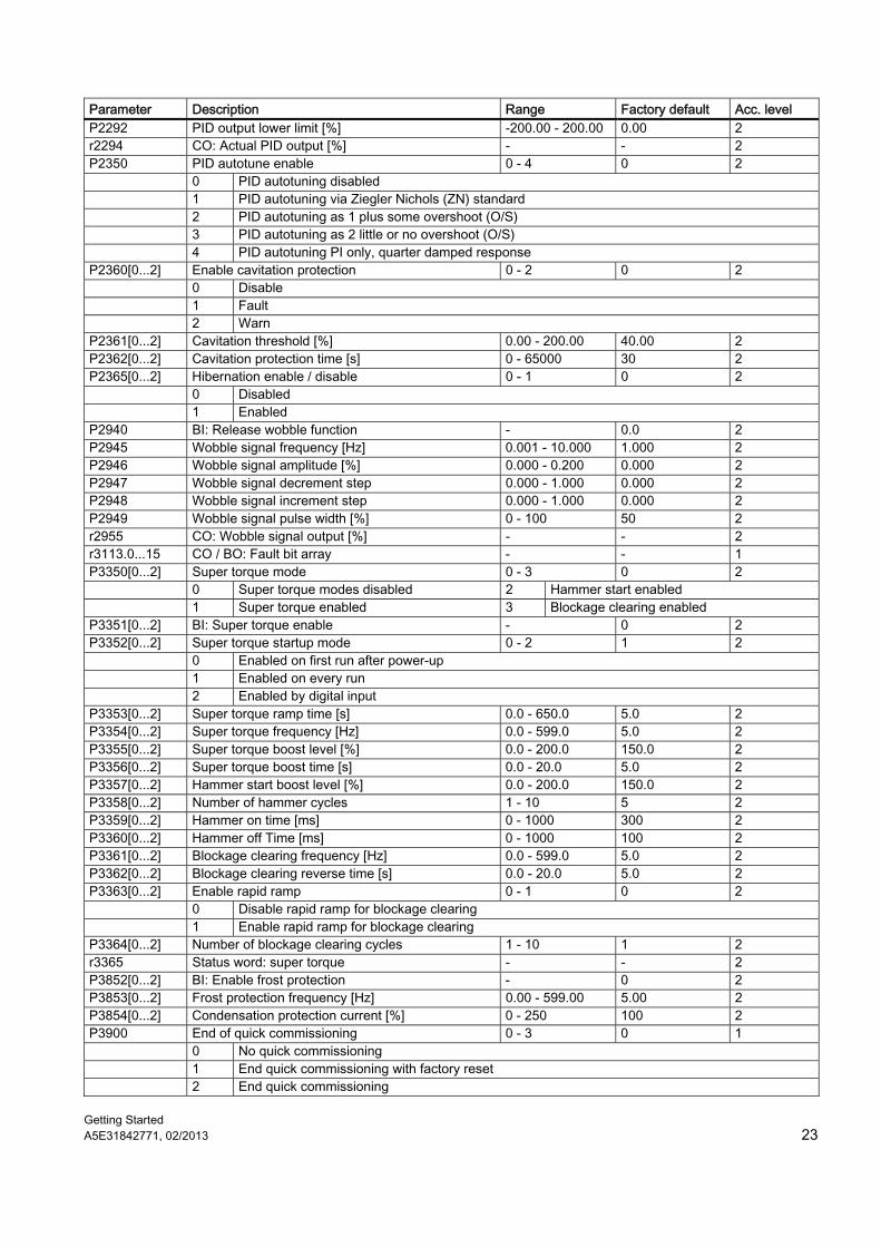
Parameter Description Range Factory default Acc. level P2292 PID output lower limit [%] -200.00 - 200.00 0.00 2 r2294 CO: Actual PID output [%] - - 2 P2350 PID autotune enable 0 - 4 0 2 0 PID autotuning disabled 1 PID autotuning via Ziegler Nichols (ZN) standard 2 PID autotuning as 1 plus some overshoot (O/S) 3 PID autotuning as 2 little or no overshoot (O/S) 4 PID autotuning PI only, quarter damped response P2360[0...2] Enable cavitation protection 0 - 2 0 2 0 Disable 1 Fault 2 Warn P2361[0...2] Cavitation threshold [%] 0.00 - 200.00 40.00 2 P2362[0...2] Cavitation protection time [s] 0 - 65000 30 2 P2365[0...2] Hibernation enable / disable 0 - 1 0 2 0 Disabled 1 Enabled P2940 BI: Release wobble function - 0.0 2 P2945 Wobble signal frequency [Hz] 0.001 - 10.000 1.000 2 P2946 Wobble signal amplitude [%] 0.000 - 0.200 0.000 2 P2947 Wobble signal decrement step 0.000 - 1.000 0.000 2 P2948 Wobble signal increment step 0.000 - 1.000 0.000 2 P2949 Wobble signal pulse width [%] 0 - 100 50 2 r2955 CO: Wobble signal output [%] - - 2 r3113.0...15 CO / BO: Fault bit array - - 1 P3350[0...2] Super torque mode 0 - 3 0 2 0 Super torque modes disabled 2 Hammer start enabled 1 Super torque enabled 3 Blockage clearing enabled P3351[0...2] BI: Super torque enable - 0 2 P3352[0...2] Super torque startup mode 0 - 2 1 2 0 Enabled on first run after power-up 1 Enabled on every run 2 Enabled by digital input P3353[0...2] Super torque ramp time [s] 0.0 - 650.0 5.0 2 P3354[0...2] Super torque frequency [Hz] 0.0 - 599.0 5.0 2 P3355[0...2] Super torque boost level [%] 0.0 - 200.0 150.0 2 P3356[0...2] Super torque boost time [s] 0.0 - 20.0 5.0 2 P3357[0...2] Hammer start boost level [%] 0.0 - 200.0 150.0 2 P3358[0...2] Number of hammer cycles 1 - 10 5 2 P3359[0...2] Hammer on time [ms] 0 - 1000 300 2 P3360[0...2] Hammer off Time [ms] 0 - 1000 100 2 P3361[0...2] Blockage clearing frequency [Hz] 0.0 - 599.0 5.0 2 P3362[0...2] Blockage clearing reverse time [s] 0.0 - 20.0 5.0 2 P3363[0...2] Enable rapid ramp 0 - 1 0 2 0 Disable rapid ramp for blockage clearing 1 Enable rapid ramp for blockage clearing P3364[0...2] Number of blockage clearing cycles 1 - 10 1 2 r3365 Status word: super torque - - 2 P3852[0...2] BI: Enable frost protection - 0 2 P3853[0...2] Frost protection frequency [Hz] 0.00 - 599.00 5.00 2 P3854[0...2] Condensation protection current [%] 0 - 250 100 2 P3900 End of quick commissioning 0 - 3 0 1 0 No quick commissioning 1 End quick commissioning with factory reset 2 End quick commissioning
Getting Started 24 A5E31842771, 02/2013
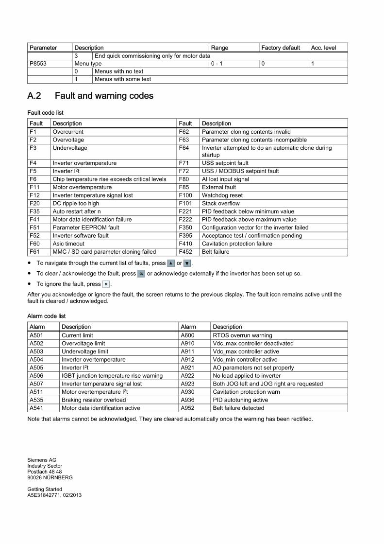
Parameter Description Range Factory default Acc. level 3 End quick commissioning only for motor data P8553 Menu type 0 - 1 0 1 0 Menus with no text 1 Menus with some text
A.2 Fault and warning codes
Fault code list
Fault Description Fault Description F1 Overcurrent F62 Parameter cloning contents invalid F2 Overvoltage F63 Parameter cloning contents incompatible F3 Undervoltage F64 Inverter attempted to do an automatic clone during
startup F4 Inverter overtemperature F71 USS setpoint fault F5 Inverter I2t F72 USS / MODBUS setpoint fault F6 Chip temperature rise exceeds critical levels F80 AI lost input signal F11 Motor overtemperature F85 External fault F12 Inverter temperature signal lost F100 Watchdog reset F20 DC ripple too high F101 Stack overflow F35 Auto restart after n F221 PID feedback below minimum value F41 Motor data identification failure F222 PID feedback above maximum value F51 Parameter EEPROM fault F350 Configuration vector for the inverter failed F52 Inverter software fault F395 Acceptance test / confirmation pending F60 Asic timeout F410 Cavitation protection failure F61 MMC / SD card parameter cloning failed F452 Belt failure
● To navigate through the current list of faults, press or .
● To clear / acknowledge the fault, press OKOK or acknowledge externally if the inverter has been set up so.
● To ignore the fault, press MM .
After you acknowledge or ignore the fault, the screen returns to the previous display. The fault icon remains active until the fault is cleared / acknowledged.
Alarm code list
Alarm Description Alarm Description A501 Current limit A600 RTOS overrun warning A502 Overvoltage limit A910 Vdc_max controller deactivated A503 Undervoltage limit A911 Vdc_max controller active A504 Inverter overtemperature A912 Vdc_min controller active A505 Inverter I2t A921 AO parameters not set properly A506 IGBT junction temperature rise warning A922 No load applied to inverter A507 Inverter temperature signal lost A923 Both JOG left and JOG right are requested A511 Motor overtemperature I2t A930 Cavitation protection warn A535 Braking resistor overload A936 PID autotuning active A541 Motor data identification active A952 Belt failure detected
Note that alarms cannot be acknowledged. They are cleared automatically once the warning has been rectified.
Siemens AG Industry Sector Postfach 48 48 90026 NÜRNBERG Getting Started A5E31842771, 02/2013