Embed Size (px)
Citation preview
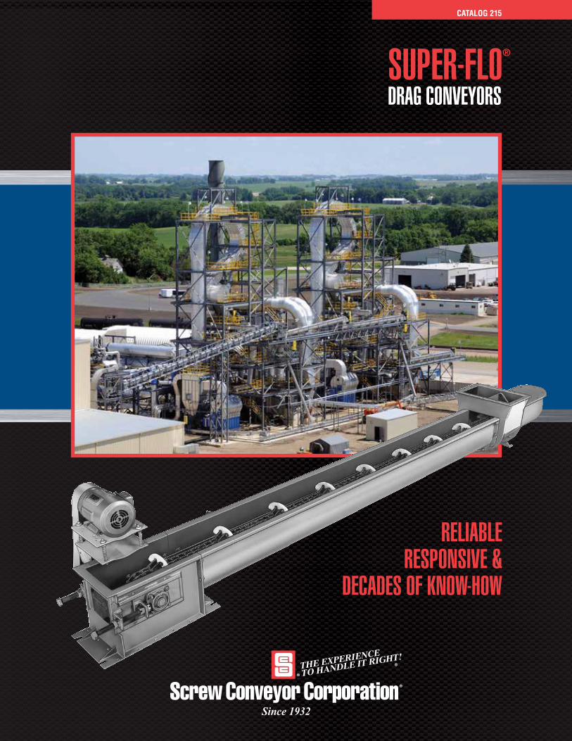
SUPER-FLO®
DRAG CONVEYORS
CATALOG 215
Since 1932
RELIABLERESPONSIVE &
DECADES OF KNOW-HOW
2
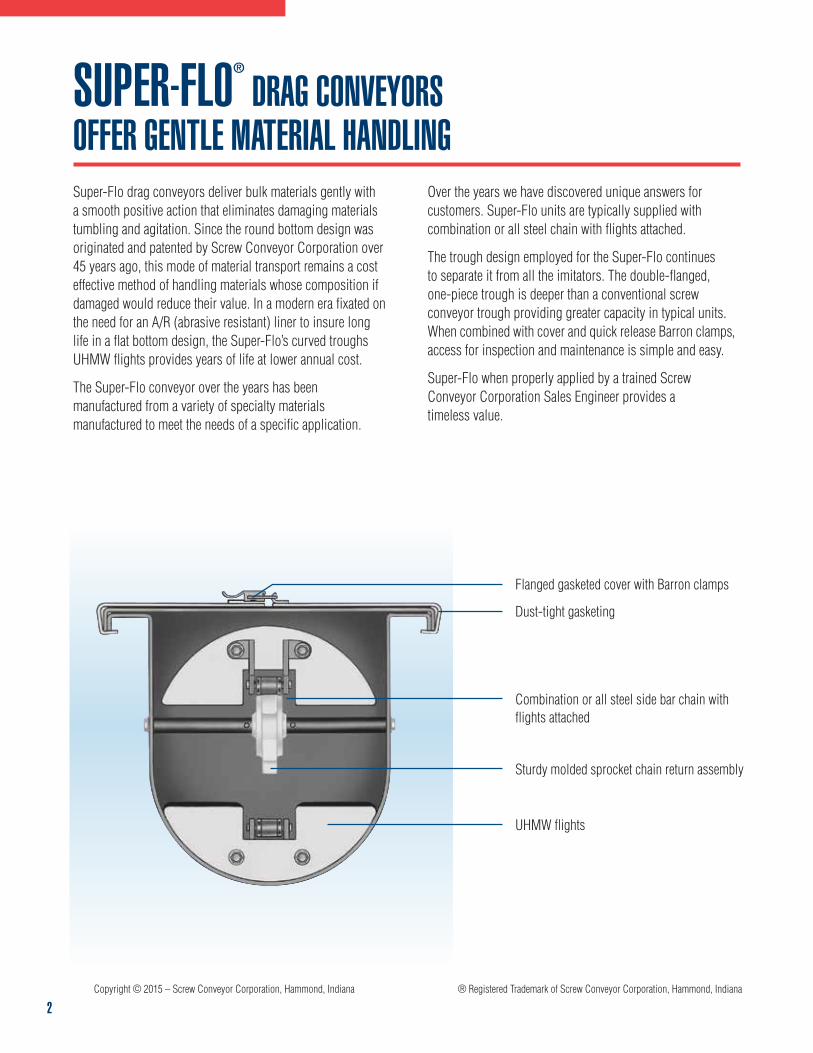
SUPER-FLO® DRAG CONVEYORSOFFER GENTLE MATERIAL HANDLINGSuper-Flo drag conveyors deliver bulk materials gently with a smooth positive action that eliminates damaging materials tumbling and agitation. Since the round bottom design was originated and patented by Screw Conveyor Corporation over 45 years ago, this mode of material transport remains a cost effective method of handling materials whose composition if damaged would reduce their value. In a modern era fixated on the need for an A/R (abrasive resistant) liner to insure long life in a flat bottom design, the Super-Flo’s curved troughs UHMW flights provides years of life at lower annual cost.
The Super-Flo conveyor over the years has been manufactured from a variety of specialty materials manufactured to meet the needs of a specific application.
Over the years we have discovered unique answers for customers. Super-Flo units are typically supplied with combination or all steel chain with flights attached.
The trough design employed for the Super-Flo continues to separate it from all the imitators. The double-flanged, one-piece trough is deeper than a conventional screw conveyor trough providing greater capacity in typical units. When combined with cover and quick release Barron clamps, access for inspection and maintenance is simple and easy.
Super-Flo when properly applied by a trained Screw Conveyor Corporation Sales Engineer provides a timeless value.
Flanged gasketed cover with Barron clamps
Dust-tight gasketing
Sturdy molded sprocket chain return assembly
UHMW flights
Copyright © 2015 – Screw Conveyor Corporation, Hammond, Indiana ® Registered Trademark of Screw Conveyor Corporation, Hammond, Indiana
Combination or all steel side bar chain with flights attached
3
SUPER-FLO® FEATURESGentle Material Handling – Materials are carried as a whole without tumbling, thereby keeping agitation and friction to a minimum. Particle degradation and separation are also minimized. Sensitive materials such as pigments, edible beans, malt, seed grains, tea and coffee are ideal for Super-Flo conveyors.
Self-Cleaning – Super-Flo conveyors are virtually self-cleaning, as the flights wipe the trough bottom after every batch.
Completely Enclosed – Keeps dusting to a minimum. The addition of battens and bolted covers with gasketed trough flanges can provide further dust-tight construction. For outside weather-tight construction, hip roof bolted covers with gaskets throughout are available.
Super-Flo Conveyor Economy – Low initial cost and low power requirements mean a more economical conveying system now and in the future, especially versus a screw conveyor.
Size Range – Super-Flo conveyors come in 10 sizes, from 6” through 24”, with capacities from 1890 to 25,765 cu. ft./hr. operating at a chain speed to 175 ft./minute.
Special Feed Sections – By-pass or pan feeders are available for a wide variety of applications. Manual or electronic control mechanisms can be used to deal with multiple products with densities from 10# to 90# for example.
Intermediate Discharges – Intermediate discharge openings are teardrop-shaped rather than rectangular. This shape allows the flights and chain to cross over without the use of crossover bars or fabricated parts, as well as allowing maximum possible discharge. Intermediate discharge spouts are furnished with curved slide gates as standard.
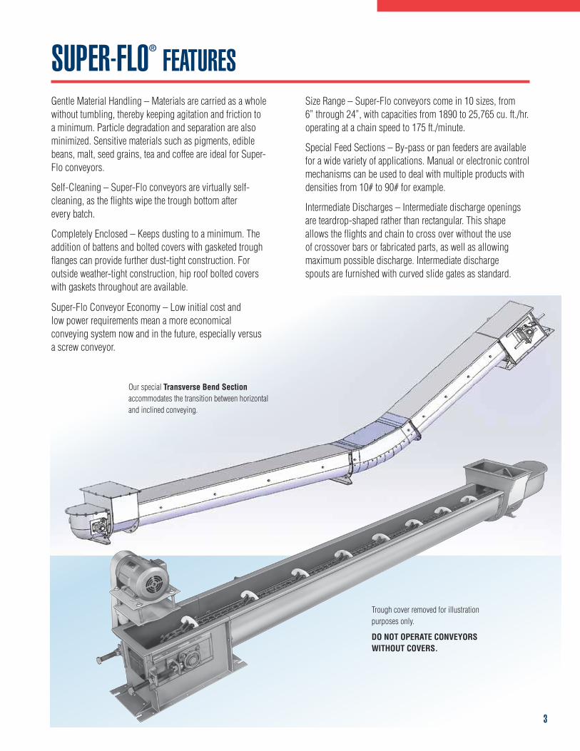
Trough cover removed for illustration purposes only.
DO NOT OPERATE CONVEYORS WITHOUT COVERS.
Our special Transverse Bend Section accommodates the transition between horizontal and inclined conveying.
12
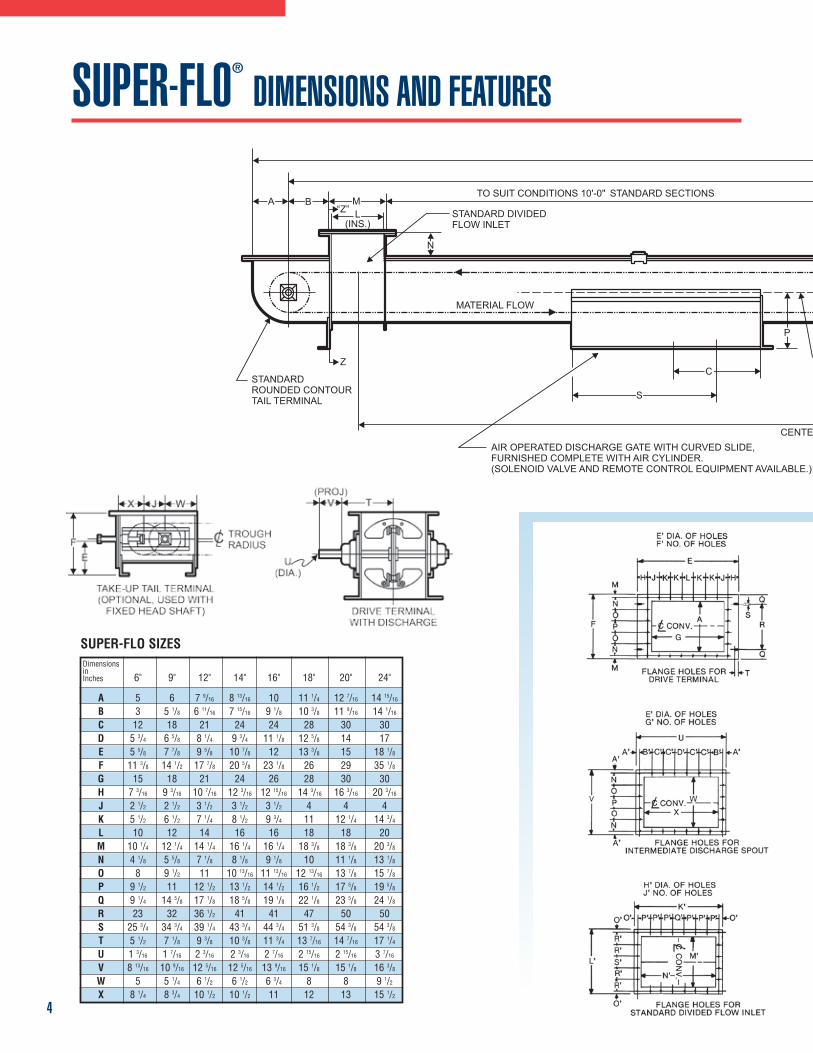
DimensionsinInches 6" 9" 12" 14" 16" 18" 20" 24"
A 5 6 7 9/16 8 13/16 10 11 1/4 12 7/16 14 15/16
B 3 5 1/8 6 11/16 7 15/16 9 1/8 10 3/8 11 9/16 14 1/16
C 12 18 21 24 24 28 30 30D 5 3/4 6 5/8 8 1/4 9 3/4 11 1/8 12 5/8 14 17E 5 5/8 7 7/8 9 5/8 10 7/8 12 13 3/8 15 18 1/8
F 11 3/8 14 1/2 17 7/8 20 5/8 23 1/8 26 29 35 1/8
G 15 18 21 24 26 28 30 30H 7 3/16 9 3/16 10 7/16 12 3/16 14 3/1612 15/16 16 3/16 20 3/16
J 2 1/2 2 1/2 3 1/2 3 1/2 3 1/2 4 4 4K 5 1/2 6 1/2 7 1/4 8 1/2 9 3/4 11 12 1/4 14 3/4
L 10 12 14 16 16 18 18 20M 10 1/4 12 1/4 14 1/4 16 1/4 16 1/4 18 3/8 18 3/8 20 3/8
N 4 1/8 5 5/8 7 1/8 8 1/8 9 1/8 10 11 1/8 13 1/8
O 8 9 1/2 11 10 13/16 11 13/16 12 13/16 13 7/8 15 7/8
P 9 1/2 11 12 1/2 13 1/2 14 1/2 16 1/2 17 5/8 19 5/8
Q 9 1/4 14 5/8 17 1/8 18 5/8 19 1/8 22 1/8 23 5/8 24 1/8
R 23 32 36 1/2 41 41 47 50 50S 25 3/4 34 3/4 39 1/4 43 3/4 44 3/4 51 3/8 54 3/8 54 3/8
T 5 1/2 7 1/8 9 3/8 10 3/8 11 3/4 13 7/16 14 7/16 17 1/4
U 1 3/16 1 7/16 2 3/16 2 3/16 2 7/16 2 15/16 2 15/16 3 7/16
V 8 13/16 10 9/16 12 5/16 12 5/16 13 9/16 15 1/8 15 1/8 16 3/8
W 5 5 1/4 6 1/2 6 1/2 6 3/4 8 8 9 1/2
X 8 1/4 8 3/4 10 1/2 10 1/2 11 12 13 15 1/2
SUPER-FLO SIZES
TO SUIT CONDITIONS 10'-0" STANDARD SECTIONS
STANDARD DIVIDEDFLOW INLET
SH
CENTER INAIR OPERATED DISCHARGE GATE WITH CURVED SLIDE,FURNISHED COMPLETE WITH AIR CYLINDER.(SOLENOID VALVE AND REMOTE CONTROL EQUIPMENT AVAILABLE.)
STANDARDROUNDED CONTOURTAIL TERMINAL
Z
A B“Z”
ML
(INS.)
N
P
MATERIAL FLOW
CC TRA
S
SUPER-FLO®
DIMENSIONS AND FEATURES
X J W
FE
TROUGHRADIUSC
TAKE-UP TAIL TERMINAL(OPTIONAL, USED WITHFIXED HEAD SHAFT)
(PROJ)V T
U(DIA.)
DRIVE TERMINALWITH DISCHARGE
108634 SCC Drag Conveyor Cat 6/5/08 11:15 AM Page 12
TO SUIT CONDITIONS 10'-0" STANDARD SECTIONS
STANDARD DIVIDEDFLOW INLET
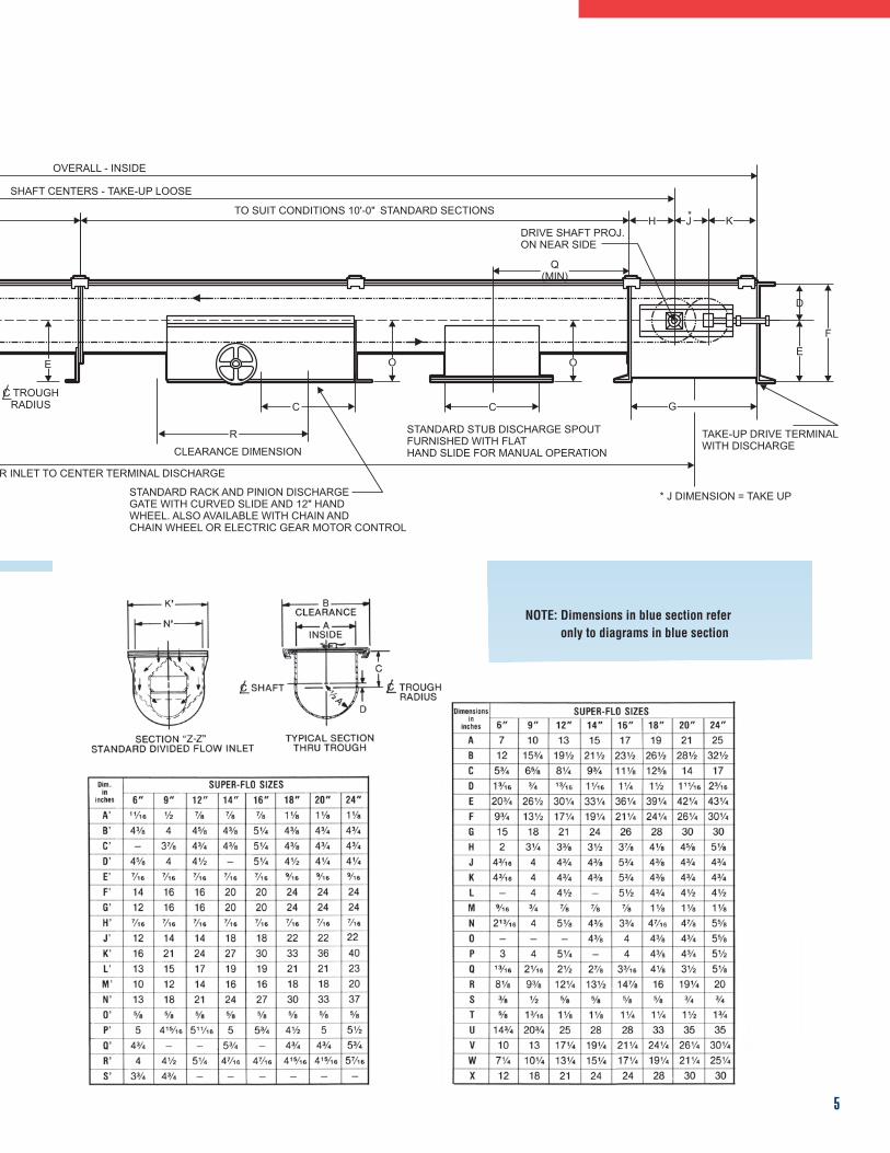
OVERALL - INSIDE
SHAFT CENTERS - TAKE-UP LOOSE
TO SUIT CONDITIONS 10'-0" STANDARD SECTIONS
DRIVE SHAFT PROJ.ON NEAR SIDE
D
TAKE-UP DRIVE TERMINALWITH DISCHARGE
* J DIMENSION = TAKE UP
STANDARD STUB DISCHARGE SPOUTFURNISHED WITH FLATHAND SLIDE FOR MANUAL OPERATION
STANDARD RACK AND PINION DISCHARGEGATE WITH CURVED SLIDE AND 12" HANDWHEEL. ALSO AVAILABLE WITH CHAIN ANDCHAIN WHEEL OR ELECTRIC GEAR MOTOR CONTROL
CLEARANCE DIMENSION
CENTER INLET TO CENTER TERMINAL DISCHARGE
AIR OPERATED DISCHARGE GATE WITH CURVED SLIDE,FURNISHED COMPLETE WITH AIR CYLINDER.(SOLENOID VALVE AND REMOTE CONTROL EQUIPMENT AVAILABLE.)
STANDARDROUNDED CONTOURTAIL TERMINAL
Z
K*JHA B
“Z”ML
(INS.)
N
F
E
Q(MIN)
OOEP
MATERIAL FLOW
CC TROUGHRADIUS
S R
C C G
4
SUPER-FLO® DIMENSIONS AND FEATURES
TO SUIT CONDITIONS 10'-0" STANDARD SECTIONS
STANDARD DIVIDEDFLOW INLET
OVERALL - INSIDE
SHAFT CENTERS - TAKE-UP LOOSE
TO SUIT CONDITIONS 10'-0" STANDARD SECTIONS
DRIVE SHAFT PROJ.ON NEAR SIDE
D
TAKE-UP DRIVE TERMINALWITH DISCHARGE
* J DIMENSION = TAKE UP
STANDARD STUB DISCHARGE SPOUTFURNISHED WITH FLATHAND SLIDE FOR MANUAL OPERATION
STANDARD RACK AND PINION DISCHARGEGATE WITH CURVED SLIDE AND 12" HANDWHEEL. ALSO AVAILABLE WITH CHAIN ANDCHAIN WHEEL OR ELECTRIC GEAR MOTOR CONTROL
CLEARANCE DIMENSION
CENTER INLET TO CENTER TERMINAL DISCHARGE
AIR OPERATED DISCHARGE GATE WITH CURVED SLIDE,FURNISHED COMPLETE WITH AIR CYLINDER.(SOLENOID VALVE AND REMOTE CONTROL EQUIPMENT AVAILABLE.)
STANDARDROUNDED CONTOURTAIL TERMINAL
Z
K*JHA B
“Z”ML
(INS.)
N
F
E
Q(MIN)
OOEP
MATERIAL FLOW
CC TROUGHRADIUS
S R
C C G
5
NOTE: Dimensions in blue section refer only to diagrams in blue section
14
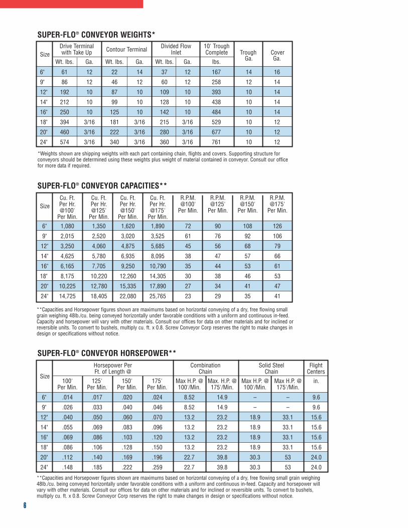
Drive Terminal Contour Terminal Divided Flow 10' TroughSize with Take Up Inlet Complete Trough Cover
Wt. lbs. Ga. Wt. lbs. Ga. Wt. lbs. Ga. lbs. Ga. Ga.
6" 61 12 22 14 37 12 167 14 16
9" 86 12 46 12 60 12 258 12 14
12" 192 10 87 10 109 10 393 10 14
14" 212 10 99 10 128 10 438 10 14
16" 250 10 125 10 142 10 484 10 14
18" 394 3/16 181 3/16 215 3/16 529 10 12
20" 460 3/16 222 3/16 280 3/16 677 10 12
24" 574 3/16 340 3/16 360 3/16 761 10 12
SUPER-FLO® CONVEYOR WEIGHTS*
SUPER-FLO® CONVEYOR CAPACITIES**
SUPER-FLO® CONVEYOR HORSEPOWER**
Cu. Ft. Cu. Ft. Cu. Ft. Cu. Ft. R.P.M. R.P.M. R.P.M. R.P.M.Size Per Hr. Per Hr. Per Hr. Per Hr. @100' @125' @150' @175'
@100' @125' @150' @175' Per Min. Per Min. Per Min. Per Min.Per Min. Per Min. Per Min. Per Min.
6" 1,080 1,350 1,620 1,890 72 90 108 126
9" 2,015 2,520 3,020 3,525 61 76 92 106
12" 3,250 4,060 4,875 5,685 45 56 68 79
14" 4,625 5,780 6,935 8,095 38 47 57 66
16" 6,165 7,705 9,250 10,790 35 44 53 61
18" 8,175 10,220 12,260 14,305 30 38 46 53
20" 10,225 12,780 15,335 17,890 27 34 41 47
24" 14,725 18,405 22,080 25,765 23 29 35 41
Horsepower Per Combination Solid Steel Flight
SizeFt. of Length @ Chain Chain Centers
100' 125' 150' 175' Max H.P. @ Max. H.P. @ Max H.P. @ Max H.P. @ in.Per Min. Per Min. Per Min. Per Min. 100'/Min. 175'/Min. 100'/Min. 175'/Min.
6" .014 .017 .020 .024 8.52 14.9 – – 9.6
9" .026 .033 .040 .046 8.52 14.9 – – 9.6
12" .040 .050 .060 .070 13.2 23.2 18.9 33.1 15.6
14" .055 .069 .083 .096 13.2 23.2 18.9 33.1 15.6
16" .069 .086 .103 .120 13.2 23.2 18.9 33.1 15.6
18" .086 .106 .128 .150 13.2 23.2 18.9 33.1 15.6
20" .112 .140 .169 .196 22.7 39.8 30.3 53 24.0
24" .148 .185 .222 .259 22.7 39.8 30.3 53 24.0
*Weights shown are shipping weights with each part containing chain, flights and covers. Supporting structure forconveyors should be determined using these weights plus weight of material contained in conveyor. Consult our officefor more data if required.
**Capacities and Horsepower figures shown are maximums based on horizontal conveying of a dry, free flowing smallgrain weighing 48lb./cu. being conveyed horizontally under favorable conditions with a uniform and continuous in-feed.Capacity and horsepower will vary with other materials. Consult our offices for data on other materials and for inclined orreversible units. To convert to bushels, multiply cu. ft. x 0.8. Screw Conveyor Corp reserves the right to make changes indesign or specifications without notice.
**Capacities and Horsepower figures shown are maximums based on horizontal conveying of a dry, free flowing small grain weighing48lb./cu. being conveyed horizontally under favorable conditions with a uniform and continuous in-feed. Capacity and horsepower willvary with other materials. Consult our offices for data on other materials and for inclined or reversible units. To convert to bushels,multiply cu. ft. x 0.8. Screw Conveyor Corp reserves the right to make changes in design or specifications without notice.
108634 SCC Drag Conveyor Cat 6/5/08 11:15 AM Page 14
6
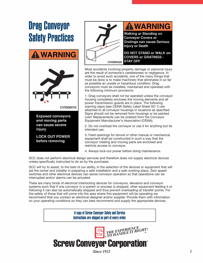
Most accidents involving property damage or personal injuryare the result of someone's carelessness or negligence. Inorder to avoid such accidents, one of the many things thatmust be done is to make machinery that eliminates in so faras possible an unsafe or hazardous condition. Dragconveyors must be installed, maintained and operated withthe following minimum provisions:
1. Drag conveyors shall not be operated unless the conveyorhousing completely encloses the moving elements and allpower transmission guards are in place. The followingwarning signs (see CEMA Safety Label Sheet SC-1) areattached to all conveyor housings in locations as specified.Signs should not be removed from housings or be paintedover! Replacements can be ordered from the ConveyorEquipment Manufacturer's Association (CEMA).
2. Do not overload the conveyor or use it for anything but itsintended use.
3. Feed openings for shovel or other manual or mechanicalequipment shall be constructed in such a way that theconveyor rotating and moving parts are enclosed andrestricts access to conveyor.
4. Always lock-out power before doing maintenance.
SCC does not perform electrical design services and therefore does not supply electrical devicesunless specifically instructed to do so by the purchaser.
SCC will try to assist, to the best of our ability, in the selection of the devices or equipment that willaid the owner and installer in preparing a safe installation and a safe working place. Zero speedswitches and other electrical devices can sense conveyor operation so that operations can beinterrupted and/or alarms can be actuated.
There are many kinds of electrical interlocking devices for conveyors, elevators and conveyorsystems such that if one conveyor in a system or process is stopped, other equipment feeding it orfollowing it can also be automatically stopped and thus prevent overloading at transfer points. Forthe safety of those that will come into the area where this equipment will be operating werecommend that you contact an electrical designer and/or supplier. Provide them with informationon your operating conditions so they can best recommend and supply the appropriate devices.
A copy of Screw Conveyor Safety and ServiceInstructions are shipped as part of every order.
Drag Conveyor Safety Practices
7Since 1932
700 Hoffman Street, Hammond, IN 46327-1894Phone 219-931-1450
www.screwconveyor.com
Winona, MSP: 662-283-3142
Visalia, CAP: 559-651-2131
Guadalajara, MéxicoP: 333-645-7110
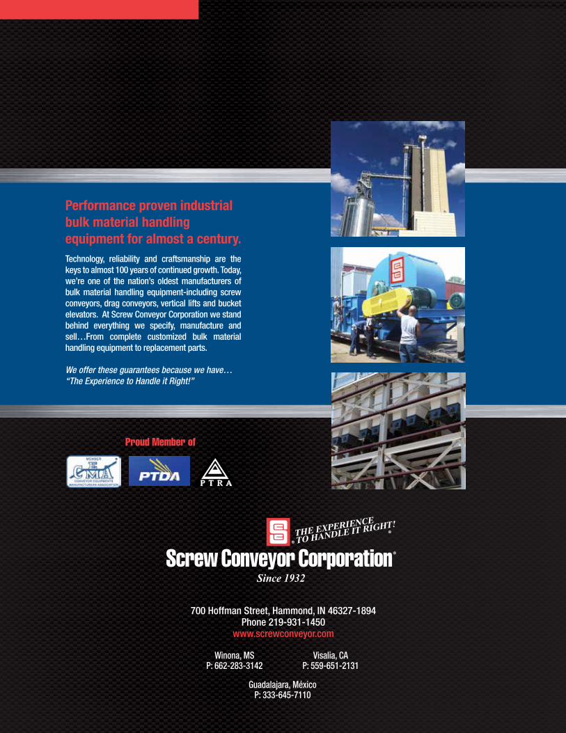
Performance proven industrial bulk material handling equipment for almost a century.Technology, reliability and craftsmanship are the keys to almost 100 years of continued growth. Today, we’re one of the nation’s oldest manufacturers of bulk material handling equipment-including screw conveyors, drag conveyors, vertical lifts and bucket elevators. At Screw Conveyor Corporation we stand behind everything we specify, manufacture and sell…From complete customized bulk material handling equipment to replacement parts.
We offer these guarantees because we have… “The Experience to Handle it Right!”
Proud Member of
Since 1932