Embed Size (px)
Citation preview

2012
November
AC-215IP Single and Double Door Access Control Unit Installation Manual

Copyright © 2012 by Rosslare. All rights reserved. This manual and the information contained herein are proprietary to REL, RSP Inc. and/or their related companies and/or subsidiaries’ (hereafter:”ROSSLARE”). Only ROSSLARE and its customers have the right to use the information.
No part of this manual may be re-produced or transmitted in any form or by any means, electronic or mechanical, for any purpose, without the express written permission of ROSSLARE.
ROSSLARE owns patents and patent applications, trademarks, copyrights, or other intellectual property rights covering the subject matter in this manual.
TEXTS, IMAGES, AND ILLUSTRATIONS INCLUDING THEIR ARRANGEMENT IN THIS DOCUMENT ARE SUBJECT TO THE PROTECTION OF COPYRIGHT LAWS AND OTHER LEGAL RIGHTS WORLDWIDE. THEIR USE, REPRODUCTION, AND TRANSMITTAL TO THIRD PARTIES WITHOUT EXPRESS WRITTEN PERMISSION MAY RESULT IN LEGAL PROCEEDINGS.
The furnishing of this manual to any party does not give that party or any third party any license to these patents, trademarks, copyrights or other intellectual property rights, except as expressly provided in any written agreement of ROSSLARE.
ROSSLARE reserves the right to revise and change this document at any time, without being obliged to announce such revisions or changes beforehand or after the fact.

Table of Contents
AC-215IP Hardware Installation Manual iii
Table of Contents 1. Introduction ....................................................................... 8 1.1 Features.............................................................................................. 9 1.2 AxTraxNG™ ..................................................................................... 10
2. Technical Specifications ................................................. 11
3. AC-215IP Panel Setup ...................................................... 13 3.1 Inputs Wiring – Non-Supervised Inputs .............................................. 14 3.2 Inputs Wiring – Supervised Inputs ..................................................... 14 3.3 Outputs Wiring ................................................................................. 15 3.4 Power Supply .................................................................................... 16 3.5 AC-215IP Access Control Panel Diagram ........................................... 18 3.6 Reader .............................................................................................. 19
4. Input and Output Connections ...................................... 20 4.1 Input Types ....................................................................................... 20 4.1.1 Normally Open Input Connection: .............................................................. 20 4.1.2 Normally Closed Input Connection ............................................................. 21 4.1.3 Normally Open Supervised Single Resistor Input Connection........................ 21 4.1.4 Normally Open Supervised Double Resistor Input Connection ...................... 22 4.1.5 Normally Closed Supervised Single Resistor Input Connection ...................... 23 4.1.6 Normally Closed Supervised Double Resistor Input Connection .................... 23 4.2 Inputs Description ............................................................................. 24 4.2.1 Request to Exit Button (REX) Input .............................................................. 24 4.2.2 Door Monitor Input ................................................................................... 24 4.2.3 General Purpose Inputs .............................................................................. 25 4.3 Outputs ............................................................................................ 25 4.4 Card Readers and Keypads ................................................................ 25
5. AC-215IP Hardware Settings .......................................... 27 5.1 DIP Switch Configuration .................................................................. 28 5.2 Access Control Panel Baud Rate ........................................................ 28
Table of Contents
iv AC-215IP Hardware Installation Manual
5.3 Access Control Panel Type ................................................................ 29 5.4 Access Control Panel Addressing ....................................................... 29
6. Communications ............................................................. 31 6.1 Serial Network Connection ............................................................... 31 6.1.1 RS-232 Connection to the Computer ......................................................... 31 6.1.2 RS-485 Connection to the Computer ......................................................... 32 6.1.3 Daisy Chaining .......................................................................................... 32 6.2 TCP/IP Network Connection .............................................................. 33 6.2.1 LAN and WAN Requirements ..................................................................... 33 6.3 Modem Network Connection ............................................................ 34 6.3.1 Hardware Requirements ............................................................................ 34 6.3.2 Prerequisites .............................................................................................. 34 6.3.3 Computer Connections .............................................................................. 34 6.3.4 AC-215IP Panel Connections ...................................................................... 35
A. Limited Warranty ............................................................ 36
List of Figures
AC-215IP Hardware Installation Manual v
List of Figures Figure 1: AC-215IP Panel ................................................................................ 9 Figure 2: Sample AC-215IP Configuration..................................................... 13 Figure 3: Inputs Wiring – Non-supervised Inputs ........................................... 14 Figure 4: Door Lock – Failed Close ................................................................ 15 Figure 5: Door Lock – Failed Open ................................................................ 16 Figure 6: Wiring Between PS-14 and AC-215IP ............................................. 17 Figure 7: AC-215IP Wiring Communications ................................................. 18 Figure 8: Reader Wiring ................................................................................ 19 Figure 9: Normally Open Input Connection ................................................... 21 Figure 10: Normally Closed Input Connection ............................................... 21 Figure 11: Normally Open Supervised Input (Single Resistor) .......................... 22 Figure 12: Normally Open Supervised Input (Double Resistor) ........................ 22 Figure 13: Normally Closed Supervised Input (Single Resistor) ........................ 23 Figure 14: Normally Closed Supervised Input (Double Resistor) ...................... 24 Figure 15: DIP Switch ................................................................................... 28 Figure 16: DIP Switch with Baud Rate Setting ............................................... 29 Figure 17: DIP Switch for Door Setting .......................................................... 29 Figure 18: DIP Switch with Internal Network Address Setting ........................ 29 Figure 19: Daisy Chaining ............................................................................. 32 Figure 20: Connecting Multiple Access Control Panels with AC-215IP ........... 33 Figure 21: Remote Site Modem Configuration .............................................. 34

List of Tables
vi AC-215IP Hardware Installation Manual
List of Tables Table 1: AxTraxNG™ Capabilities ................................................................. 10 Table 2: Possible Hardware Settings .............................................................. 27 Table 3: DIP Switches and their Functions ..................................................... 28 Table 4: Switch Baud Rates ........................................................................... 29 Table 5: Available Panel Addresses ............................................................... 30 Table 6: RS-232 Connection ......................................................................... 31

Notice and Disclaimer
AC-215IP Hardware Installation Manual vii
Notice and Disclaimer This manual’s sole purpose is to assist installers and/or users in the safe and efficient installation and usage of the system and/or product, and/or software described herein.
BEFORE ATTEMPTING TO INSTALL AND/OR USE THE SYSTEM, THE INSTALLER AND
THE USER MUST READ THIS MANUAL AND BECOME FAMILIAR WITH ALL SAFETY
REQUIREMENTS AND OPERATING PROCEDURES. The system must not be used for purposes other than those for which it
was designed.
The use of the software associated with the system and/or product, if applicable, is subject to the terms of the license provided as part of the purchase documents.
ROSSLARE ENTERPRISES LIMITED and/or its related companies and/or subsidiaries’ (hereafter:"ROSSLARE") exclusive warranty and liability is limited to the warranty and liability statement provided in an appendix at the end of this document.
This manual describes the maximum configuration of the system with the maximum number of functions, including future options. Therefore, not all functions described in this manual may be available in the specific system and/or product configuration you purchased.
Incorrect operation or installation, or failure of the user to effectively maintain the system, relieves the manufacturer (and seller) from all or any responsibility for consequent noncompliance, damage, or injury.
The text, images and graphics contained in the manual are for the purpose of illustration and reference only.
In no event shall manufacturer be liable for any special, direct, indirect, incidental, consequential, exemplary or punitive damages (including, without limitation, any and all damages from business interruption, loss of profits or revenue, cost of capital or loss of use of any property or capital or injury).
All graphics in this manual are for reference only, some deviation between the image(s) and the actual product may occur.
All wiring diagrams are intended for reference only, the photograph or graphic of the PCB(s) are intended for clearer illustration and understanding of the product and may differ from the actual PCB(s).

Introduction
8 AC-215IP Hardware Installation Manual
1. Introduction AC-215IP access control panels are state-of-the-art networked access controllers, employing the latest technology to meet the requirements of the market.
When used in combination with Rosslare's AxTraxNG™ software system, the AC-215IP gives you full control over access to your premises. The system can control both single and double door entrances. AC-215IP supports up to 30,000 users and uses flash memory to enable easy firmware upgrades.
For more information on the AxTraxNG™ system, refer to the AxTraxNG™ Access Control Software Manual.
The AC-215IP consists of the following components:
AC-215IP controller board
Panel enclosure
PS-14 power supply
Power Transformer (not included with the AC-215U)
4 x 2.2 K and 4 x 8.2 K resistors for the supervised inputs.
The AC-215IP also includes on-board support for communications across a TCP/IP network.
Introduction
AC-215IP Hardware Installation Manual 9
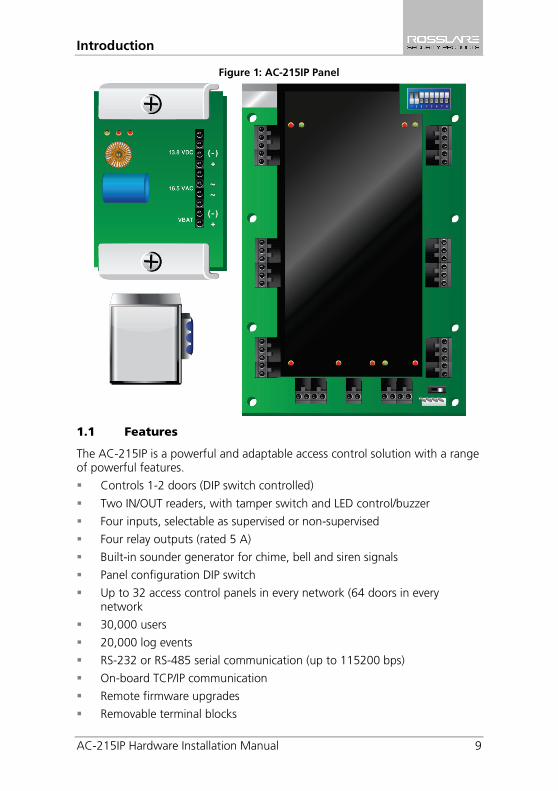
Figure 1: AC-215IP Panel
1.1 Features
The AC-215IP is a powerful and adaptable access control solution with a range of powerful features.
Controls 1-2 doors (DIP switch controlled)
Two IN/OUT readers, with tamper switch and LED control/buzzer
Four inputs, selectable as supervised or non-supervised
Four relay outputs (rated 5 A)
Built-in sounder generator for chime, bell and siren signals
Panel configuration DIP switch
Up to 32 access control panels in every network (64 doors in every network
30,000 users
20,000 log events
RS-232 or RS-485 serial communication (up to 115200 bps)
On-board TCP/IP communication
Remote firmware upgrades
Removable terminal blocks
Introduction
10 AC-215IP Hardware Installation Manual
1.2 AxTraxNG™
The AxTraxNG™ software system is custom designed to set up, manage, and supervise all aspects of an access panel network.
Table 1 presents the AxTraxNG™ software capabilities: Table 1: AxTraxNG™ Capabilities
Users capacity 30000
Unauthorized Users 30000
Access groups 30000
Number of panels in system 1023
Number of doors in system 2046
These options are software and firmware dependent, and may change in later releases or revisions.

Technical Specifications
AC-215IP Hardware Installation Manual 11
2. Technical Specifications
Electrical Characteristics Operating Voltage 12 VDC 2 A from PS-14
Maximum Input Current Standby: 120 mA Maximum: 370 mA
General Inputs 4 supervised high impedance inputs. Maximum voltage: 5 VDC
Relay Outputs 4 Relay outputs 5 A Relay N.O. and N.C. options
Reader Ports 2 reader ports Output voltage: 12 VDC Max. current: 300 mA LED control output D0/D1, tamper input
Visual Indicators 11 LEDs
Audio Built in sounder (bell, chime and siren)
Battery Standby Time 3 hours (with 12 V, 7 Ah battery)
Communication Characteristics RS-232 Terminal Block
RS-485 Molex and Terminal Block
TCP/IP On-board RJ-45 connector
Speed Options 9600 bps 19200 bps 57600 bps 115200 bps
Environmental Characteristics Operating Temperature Range 32°F to 120°F (0°C to 49°C)
Operating Humidity 0 to 85% (non-condensing)
Dimensions Height x Width x Depth 10.4 x 13.2 x 3.4 in. (264 x 334 x 84.5 mm)
Weight 8.38 lbs. (3.81 kg)
Transformer (for AC-215IP only) AC Transformer 120/220 VAC, 16 VAC 2.5 A (60 VA)

Technical Specifications
12 AC-215IP Hardware Installation Manual
Power Supply Specifications Input Voltage 16 VAC, 4 A
From Transformer – Backup Battery Charger
12 VDC Lead Acid battery up to 7 Ah
From Transformer – Output Voltage 1
12 VDC, 0.5 A
Access control panel – Output Voltage 2
13.8 VDC, 1.5 A
Power Supply Indication Tamper Output (open collector) Indicates faulty power
Power LEDs Power In (AC) – Green LED1 Main power
Power Out (DC) – Red LED2 Low voltage
Low Battery – Red LED3 Backup battery low voltage
AC-215IP Panel Setup
AC-215IP Hardware Installation Manual 13
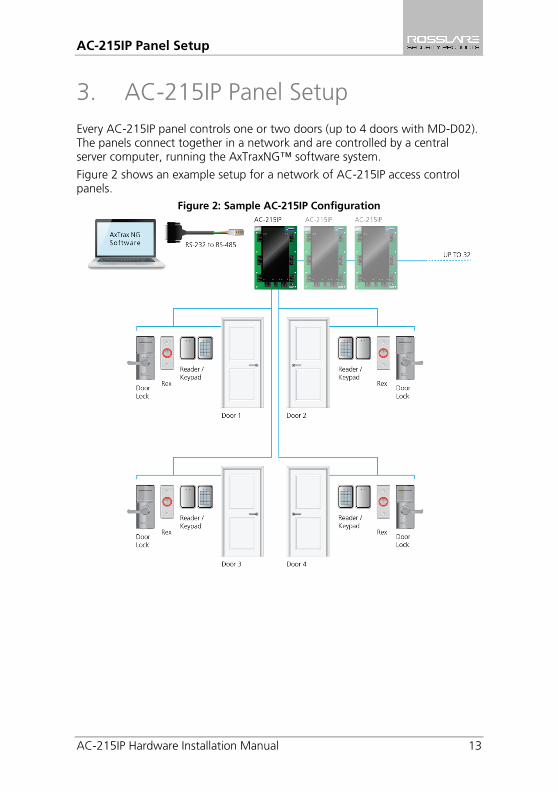
3. AC-215IP Panel Setup Every AC-215IP panel controls one or two doors (up to 4 doors with MD-D02). The panels connect together in a network and are controlled by a central server computer, running the AxTraxNG™ software system.
Figure 2 shows an example setup for a network of AC-215IP access control panels.
Figure 2: Sample AC-215IP Configuration
AC-215IP Panel Setup
14 AC-215IP Hardware Installation Manual
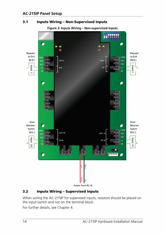
3.1 Inputs Wiring – Non-Supervised Inputs
Figure 3: Inputs Wiring – Non-supervised Inputs
3.2 Inputs Wiring – Supervised Inputs
When wiring the AC-215IP for supervised inputs, resistors should be placed on the input switch and not on the terminal block.
For further details, see Chapter 4.
AC-215IP Panel Setup
AC-215IP Hardware Installation Manual 15
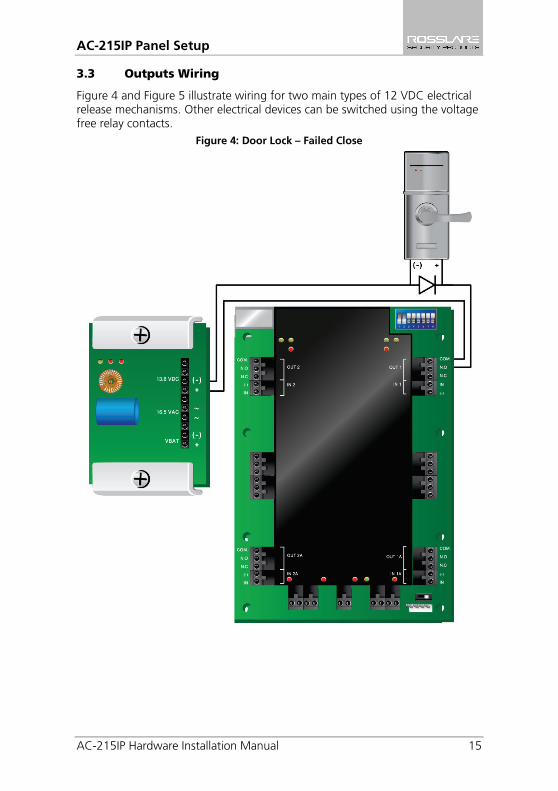
3.3 Outputs Wiring
Figure 4 and Figure 5 illustrate wiring for two main types of 12 VDC electrical release mechanisms. Other electrical devices can be switched using the voltage free relay contacts.
Figure 4: Door Lock – Failed Close
AC-215IP Panel Setup
16 AC-215IP Hardware Installation Manual
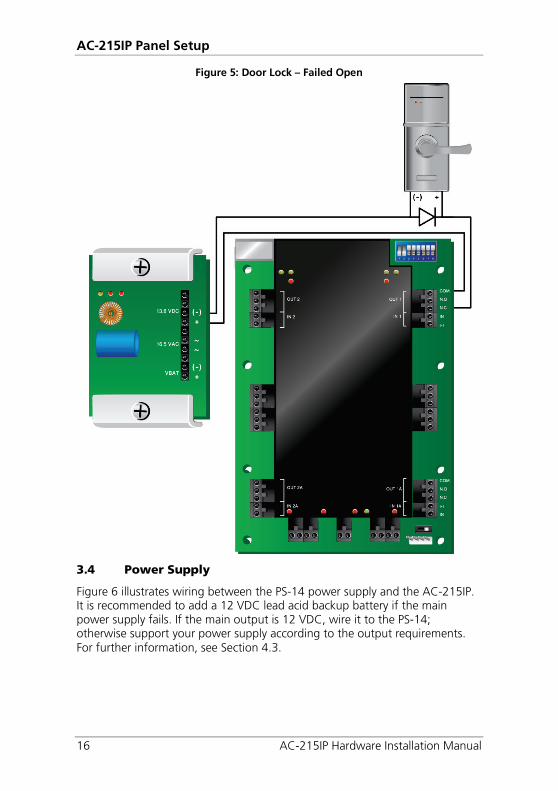
Figure 5: Door Lock – Failed Open
3.4 Power Supply
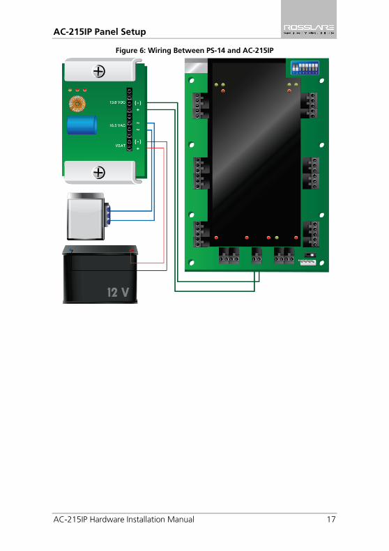
Figure 6 illustrates wiring between the PS-14 power supply and the AC-215IP. It is recommended to add a 12 VDC lead acid backup battery if the main power supply fails. If the main output is 12 VDC, wire it to the PS-14; otherwise support your power supply according to the output requirements. For further information, see Section 4.3.
AC-215IP Panel Setup
AC-215IP Hardware Installation Manual 17
Figure 6: Wiring Between PS-14 and AC-215IP
AC-215IP Panel Setup
18 AC-215IP Hardware Installation Manual
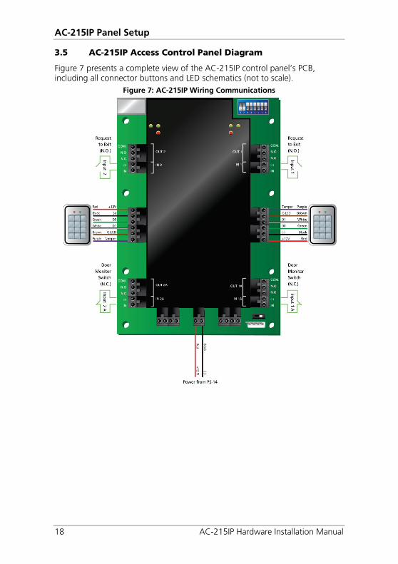
3.5 AC-215IP Access Control Panel Diagram
Figure 7 presents a complete view of the AC-215IP control panel’s PCB, including all connector buttons and LED schematics (not to scale).
Figure 7: AC-215IP Wiring Communications
AC-215IP Panel Setup
AC-215IP Hardware Installation Manual 19
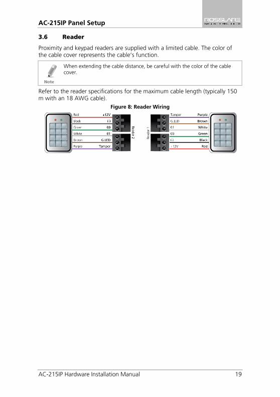
3.6 Reader
Proximity and keypad readers are supplied with a limited cable. The color of the cable cover represents the cable’s function.
When extending the cable distance, be careful with the color of the cable cover.
Refer to the reader specifications for the maximum cable length (typically 150 m with an 18 AWG cable).
Figure 8: Reader Wiring
Input and Output Connections
20 AC-215IP Hardware Installation Manual
4. Input and Output Connections This chapter describes the AC-215IP access control panel's input and output connections.
4.1 Input Types
There are four input types – Normally Open, Normally Closed, Normally Open Supervised 1 or 2 resistors, and Normally Closed Supervised 1 or 2 resistors.
Inputs IN1, IN1A, IN2 and IN2A may be configured individually as either supervised or non-supervised inputs. Configure each input separately via the AxTraxNG™ system.
Non-supervised inputs have two states:
Normal State
Abnormal State
Supervised inputs have three states:
Normal State
Abnormal State
Trouble State
The Trouble state is caused by either tampering with the input circuit or by faulty hardware installation. Once configured as supervised input, add a resistor of 2.2 K, of 8.2 K, or both on the input circuit. See the figures in the following subsections.
4.1.1 Normally Open Input Connection: Normally Open Input has 2 states:
Switch Open – Normal State:
Loop resistance = Infinite (open circuit)
Switch Closed – Abnormal State:
Loop resistance = 0 (short circuit)
Input and Output Connections
AC-215IP Hardware Installation Manual 21
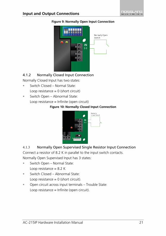
Figure 9: Normally Open Input Connection
4.1.2 Normally Closed Input Connection
Normally Closed Input has two states:
Switch Closed – Normal State:
Loop resistance = 0 (short circuit)
Switch Open – Abnormal State:
Loop resistance = Infinite (open circuit) Figure 10: Normally Closed Input Connection
4.1.3 Normally Open Supervised Single Resistor Input Connection Connect a resistor of 8.2 K in parallel to the input switch contacts.
Normally Open Supervised Input has 3 states:
Switch Open – Normal State:
Loop resistance = 8.2 K
Switch Closed – Abnormal State:
Loop resistance = 0 (short circuit).
Open circuit across input terminals – Trouble State:
Loop resistance = Infinite (open circuit).
Input and Output Connections
22 AC-215IP Hardware Installation Manual
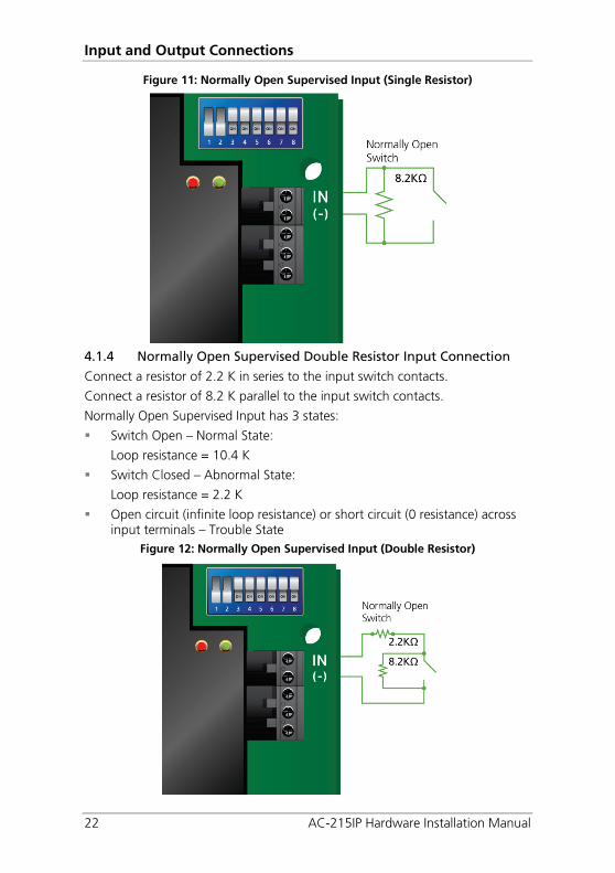
Figure 11: Normally Open Supervised Input (Single Resistor)
4.1.4 Normally Open Supervised Double Resistor Input Connection
Connect a resistor of 2.2 K in series to the input switch contacts.
Connect a resistor of 8.2 K parallel to the input switch contacts.
Normally Open Supervised Input has 3 states:
Switch Open – Normal State:
Loop resistance = 10.4 K
Switch Closed – Abnormal State:
Loop resistance = 2.2 K
Open circuit (infinite loop resistance) or short circuit (0 resistance) across input terminals – Trouble State
Figure 12: Normally Open Supervised Input (Double Resistor)
Input and Output Connections
AC-215IP Hardware Installation Manual 23
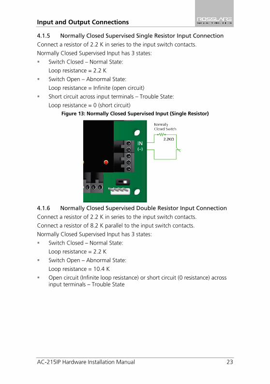
4.1.5 Normally Closed Supervised Single Resistor Input Connection
Connect a resistor of 2.2 K in series to the input switch contacts.
Normally Closed Supervised Input has 3 states:
Switch Closed – Normal State:
Loop resistance = 2.2 K
Switch Open – Abnormal State:
Loop resistance = Infinite (open circuit)
Short circuit across input terminals – Trouble State:
Loop resistance = 0 (short circuit) Figure 13: Normally Closed Supervised Input (Single Resistor)
4.1.6 Normally Closed Supervised Double Resistor Input Connection
Connect a resistor of 2.2 K in series to the input switch contacts.
Connect a resistor of 8.2 K parallel to the input switch contacts.
Normally Closed Supervised Input has 3 states:
Switch Closed – Normal State:
Loop resistance = 2.2 K
Switch Open – Abnormal State:
Loop resistance = 10.4 K
Open circuit (Infinite loop resistance) or short circuit (0 resistance) across input terminals – Trouble State
Input and Output Connections
24 AC-215IP Hardware Installation Manual
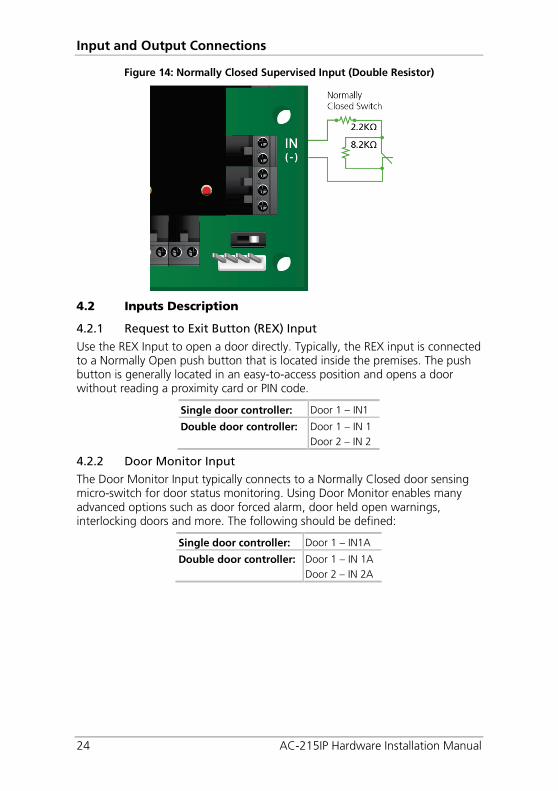
Figure 14: Normally Closed Supervised Input (Double Resistor)
4.2 Inputs Description
4.2.1 Request to Exit Button (REX) Input
Use the REX Input to open a door directly. Typically, the REX input is connected to a Normally Open push button that is located inside the premises. The push button is generally located in an easy-to-access position and opens a door without reading a proximity card or PIN code.
Single door controller: Door 1 – IN1
Double door controller: Door 1 – IN 1 Door 2 – IN 2
4.2.2 Door Monitor Input
The Door Monitor Input typically connects to a Normally Closed door sensing micro-switch for door status monitoring. Using Door Monitor enables many advanced options such as door forced alarm, door held open warnings, interlocking doors and more. The following should be defined:
Single door controller: Door 1 – IN1A
Double door controller: Door 1 – IN 1A Door 2 – IN 2A
Input and Output Connections
AC-215IP Hardware Installation Manual 25
4.2.3 General Purpose Inputs
These are free inputs that can be used for various functions. The following should be defined:
Single door controller: Door 1 – IN 2 Door 1 – IN 2A
Double door controller: No general purpose inputs available
General purpose inputs are suitable for most uses. For example, they might be used to detect tampering, to activate alarm sensors or for monitoring power supply failure.
4.3 Outputs
Rosslare Security recommends the use of suppression diodes for all outputs that activate an inductive load.
Door Lock
There are two types of door locking devices:
Fail open (fail secure)
Fail close (fail safe)
The following should be defined:
Single door controller: Door 1 – OUT 1
Double door controller: Door 1 – OUT 1 Door 2 – OUT 2
The output can sink current from any power supply (see Section 3.4).
For UL installations, the installer must configure the system as fail-safe to comply with NFPA (National Fire Protection Association) regulations.
4.4 Card Readers and Keypads
Each access control panel can be connected to a maximum of two readers. There are three available types of reader:
Card readers
Keypads
Dual keypad card readers
A keypad is required for any reader mode that requires PIN code entries, such as "Card or PIN", "PIN Only" or "Card and PIN (Secured mode)".
Input and Output Connections
26 AC-215IP Hardware Installation Manual
When connecting a reader, the following should be defined:
Single door controller: Door 1 – Reader 1 IN/OUT Door 1 – Reader 2 OUT/ IN
Double door controller: Door 1 – Reader 1 IN/OUT Door 2 – Reader 2 IN/OUT
Use the AxTraxNG™ software to set the readers for IN or OUT use and to set the data transmission format for each reader.
The reader’s tamper output connects to the access control panel's Reader-Tamper input. If the reader is interfered with, an alarm can be generated.
The panel's Reader G.LED output activates the reader’s green LED input when operating in "Card and PIN" secure mode. While this mode is in force, users must enter a PIN on the keypad immediately after entering the card.
The controller activates the LED control for 2 seconds when an access granted event occurs.

AC-215IP Hardware Settings
AC-215IP Hardware Installation Manual 27
5. AC-215IP Hardware Settings Each AC-215IP panel controls an entrance. The behavior of the panel is controlled by DIP switch settings.
Select the appropriate DIP switch setting to operate the panel as either a single door, a double door, or four doors (see Section 5.3).
Access control panels configured as either single door or double door controllers have two readers, IN or OUT.
Table 2 summarizes the possible hardware settings. Table 2: Possible Hardware Settings
Single Door:
Outputs Door Lock output (OUT 1)
General purpose output (OUT 1A)
General purpose output (OUT 2)
General purpose output (OUT 2A)
Inputs Request to exit (IN 1)
Door monitor input (IN 1A)
General purpose input (IN 2)
General purpose input (IN 2A)
Readers Reader1 Door Entry or Exit
Reader2 Door Exit or Entry
Double door:
Outputs Door1 Lock output (OUT 1)
General purpose output (OUT 1A)
Door2 Lock output (OUT 2)
General purpose output (OUT 2A)
Inputs Door1 Request to exit (IN 1)
Door1 monitor input (IN 1A)
Door2 Request to exit (IN 2)
Door2 monitor input (IN 2A)
Readers Reader1 (Door1 IN/OUT)
Reader2 (Door2 IN/OUT)
AC-215IP Hardware Settings
28 AC-215IP Hardware Installation Manual
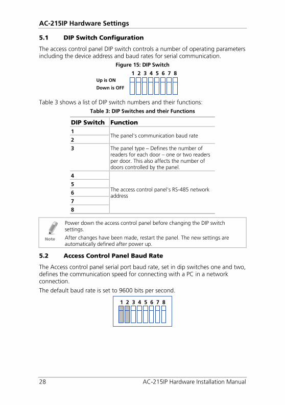
5.1 DIP Switch Configuration
The access control panel DIP switch controls a number of operating parameters including the device address and baud rates for serial communication.
Figure 15: DIP Switch
Table 3 shows a list of DIP switch numbers and their functions:
Table 3: DIP Switches and their Functions
DIP Switch Function 1
The panel's communication baud rate 2
3 The panel type – Defines the number of readers for each door – one or two readers per door. This also affects the number of doors controlled by the panel.
4
The access control panel's RS-485 network address
5
6
7
8
Power down the access control panel before changing the DIP switch settings.
After changes have been made, restart the panel. The new settings are automatically defined after power up.
5.2 Access Control Panel Baud Rate
The Access control panel serial port baud rate, set in dip switches one and two, defines the communication speed for connecting with a PC in a network connection.
The default baud rate is set to 9600 bits per second.
1 2 3 4 5 6 7 8
1 2 3 4 5 6 7 8 Up is ON
Down is OFF
AC-215IP Hardware Settings
AC-215IP Hardware Installation Manual 29
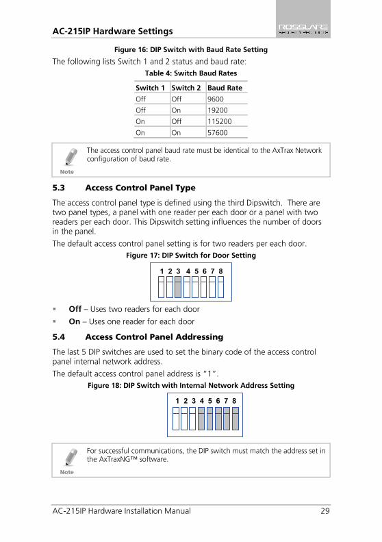
Figure 16: DIP Switch with Baud Rate Setting
The following lists Switch 1 and 2 status and baud rate: Table 4: Switch Baud Rates
Switch 1 Switch 2 Baud Rate
Off Off 9600
Off On 19200
On Off 115200
On On 57600
The access control panel baud rate must be identical to the AxTrax Network configuration of baud rate.
5.3 Access Control Panel Type
The access control panel type is defined using the third Dipswitch. There are two panel types, a panel with one reader per each door or a panel with two readers per each door. This Dipswitch setting influences the number of doors in the panel.
The default access control panel setting is for two readers per each door. Figure 17: DIP Switch for Door Setting
Off – Uses two readers for each door
On – Uses one reader for each door
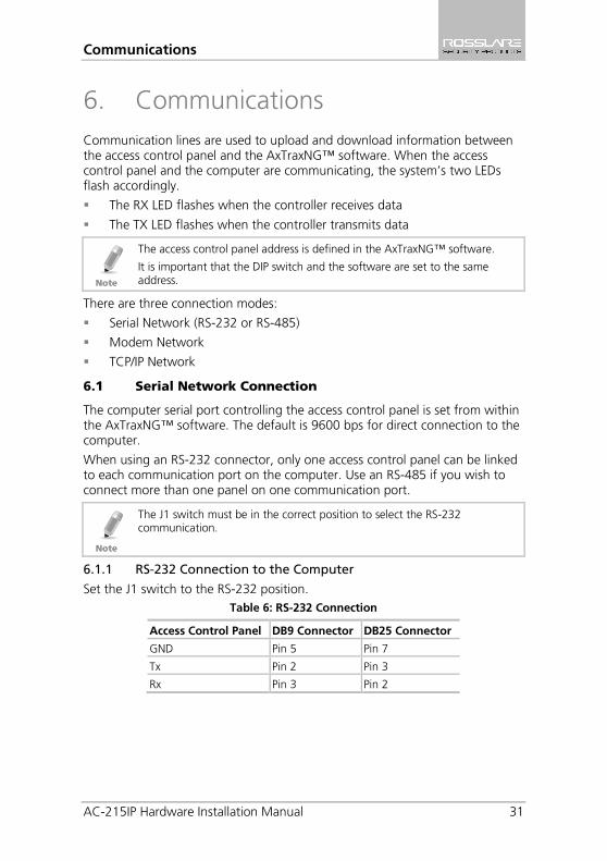
5.4 Access Control Panel Addressing
The last 5 DIP switches are used to set the binary code of the access control panel internal network address.
The default access control panel address is “1”. Figure 18: DIP Switch with Internal Network Address Setting
For successful communications, the DIP switch must match the address set in the AxTraxNG™ software.
1 2 3 4 5 6 7 8
1 2 3 4 5 6 7 8
AC-215IP Hardware Settings
30 AC-215IP Hardware Installation Manual
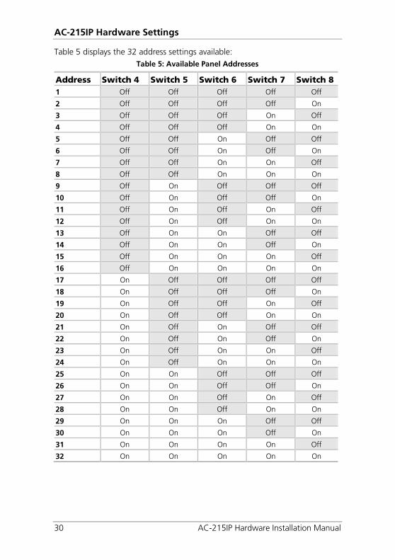
Table 5 displays the 32 address settings available: Table 5: Available Panel Addresses
Address Switch 4 Switch 5 Switch 6 Switch 7 Switch 8 1 Off Off Off Off Off
2 Off Off Off Off On
3 Off Off Off On Off
4 Off Off Off On On
5 Off Off On Off Off
6 Off Off On Off On
7 Off Off On On Off
8 Off Off On On On
9 Off On Off Off Off
10 Off On Off Off On
11 Off On Off On Off
12 Off On Off On On
13 Off On On Off Off
14 Off On On Off On
15 Off On On On Off
16 Off On On On On
17 On Off Off Off Off
18 On Off Off Off On
19 On Off Off On Off
20 On Off Off On On
21 On Off On Off Off
22 On Off On Off On
23 On Off On On Off
24 On Off On On On
25 On On Off Off Off
26 On On Off Off On
27 On On Off On Off
28 On On Off On On
29 On On On Off Off
30 On On On Off On
31 On On On On Off
32 On On On On On
Communications
AC-215IP Hardware Installation Manual 31
6. Communications Communication lines are used to upload and download information between the access control panel and the AxTraxNG™ software. When the access control panel and the computer are communicating, the system’s two LEDs flash accordingly.
The RX LED flashes when the controller receives data
The TX LED flashes when the controller transmits data
The access control panel address is defined in the AxTraxNG™ software.
It is important that the DIP switch and the software are set to the same address.
There are three connection modes:
Serial Network (RS-232 or RS-485)
Modem Network
TCP/IP Network
6.1 Serial Network Connection
The computer serial port controlling the access control panel is set from within the AxTraxNG™ software. The default is 9600 bps for direct connection to the computer.
When using an RS-232 connector, only one access control panel can be linked to each communication port on the computer. Use an RS-485 if you wish to connect more than one panel on one communication port.
The J1 switch must be in the correct position to select the RS-232 communication.
6.1.1 RS-232 Connection to the Computer
Set the J1 switch to the RS-232 position. Table 6: RS-232 Connection
Access Control Panel DB9 Connector DB25 Connector
GND Pin 5 Pin 7
Tx Pin 2 Pin 3
Rx Pin 3 Pin 2
Communications
32 AC-215IP Hardware Installation Manual
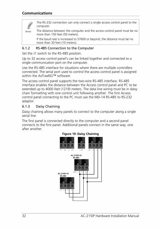
The RS-232 connection can only connect a single access control panel to the computer.
The distance between the computer and the access control panel must be no more than 150 feet (50 meters).
If the baud rate is increased to 57600 or beyond, the distance must be no more than 30 feet (10 meters).
6.1.2 RS-485 Connection to the Computer
Set the J1 switch to the RS-485 position.
Up to 32 access control panel's can be linked together and connected to a single communication port on the computer.
Use the RS-485 interface for situations where there are multiple controllers connected. The serial port used to control the access control panel is assigned within the AxTraxNG™ software.
The access control panel supports the two-wire RS-485 interface. RS-485 interface enables the distance between the Access control panel and PC to be extended up to 4000 feet (1219) meters. The data line wiring must be in daisy chain formatting with one control unit following another. The first Access control panel connecting to the PC must use the MD-14 RS-485 to RS-232 adaptor.
6.1.3 Daisy Chaining
Daisy chaining allows many panels to connect to the computer along a single serial line.
The first panel is connected directly to the computer and a second panel connects to the first panel. Additional panels connect in the same way, one after another.
Figure 19: Daisy Chaining
AC-215IP #2 RS-485
AC-215IP #3 RS-485
Communications
AC-215IP Hardware Installation Manual 33
At each end of the data line, both where the panel connects to the computer and on the last panel in the network, a termination resistor of 120 Ω may be required. Apply the resistor across the L1 and L2 connections.
These termination resistors are especially important in long cable runs.
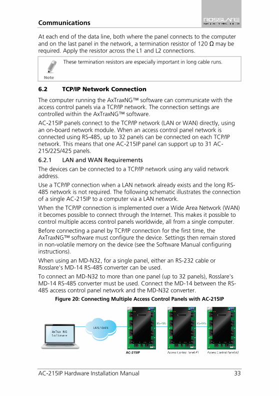
6.2 TCP/IP Network Connection
The computer running the AxTraxNG™ software can communicate with the access control panels via a TCP/IP network. The connection settings are controlled within the AxTraxNG™ software.
AC-215IP panels connect to the TCP/IP network (LAN or WAN) directly, using an on-board network module. When an access control panel network is connected using RS-485, up to 32 panels can be connected on each TCP/IP network. This means that one AC-215IP panel can support up to 31 AC-215/225/425 panels.
6.2.1 LAN and WAN Requirements
The devices can be connected to a TCP/IP network using any valid network address.
Use a TCP/IP connection when a LAN network already exists and the long RS-485 network is not required. The following schematic illustrates the connection of a single AC-215IP to a computer via a LAN network.
When the TCP/IP connection is implemented over a Wide Area Network (WAN) it becomes possible to connect through the Internet. This makes it possible to control multiple access control panels worldwide, all from a single computer.
Before connecting a panel by TCP/IP connection for the first time, the AxTraxNG™ software must configure the device. Settings then remain stored in non-volatile memory on the device (see the Software Manual configuring instructions).
When using an MD-N32, for a single panel, either an RS-232 cable or Rosslare's MD-14 RS-485 converter can be used.
To connect an MD-N32 to more than one panel (up to 32 panels), Rosslare's MD-14 RS-485 converter must be used. Connect the MD-14 between the RS-485 access control panel network and the MD-N32 converter.
Figure 20: Connecting Multiple Access Control Panels with AC-215IP
AC-215IP

Communications
34 AC-215IP Hardware Installation Manual
6.3 Modem Network Connection
Access control panels can be controlled from the computer's modem. The modem is assigned from within the AxTraxNG™ software.
Use a modem when the access control panel is too far from the computer to use a serial connection and an alternative RS-232/RS-485 network or TCP/IP network is unavailable.
The following diagram illustrates remote site modem configuration with AC-215IP.
Figure 21: Remote Site Modem Configuration
For more information on modem connections, refer to the MD-N33 User Manual and the AxTraxNG™ software manual.
6.3.1 Hardware Requirements
2 Standard Telephone cables – RJ11 plugs in both sides
Crossed 9-pin RS-232 cable (female jack on both sides)
Rosslare MD-14 (RS-232 to RS-485 converter)
2 Rosslare MD-N33 (Modem to serial gateway)
Rosslare AC-215IP panel
6.3.2 Prerequisites
Before performing permanent modem installations, the modem that will be connected to the panel must be initialized from the computer running the AxTraxNG™ software.
6.3.3 Computer Connections
The MD-N33 must connect to the computer via a serial port.
To connect to the PC: 1. Connect a 9 VDC adapter to the first MD-N33. Make sure that the power
LED (Red) is on.
2. Connect the PC, using an available COM port, to the MD-N33 with the crossed 9-pin RS-232 cable.
3. Connect the MD-N33's RJ11 jack to the telephone line using the telephone cable.

Communications
AC-215IP Hardware Installation Manual 35
6.3.4 AC-215IP Panel Connections
1. Connect a 9 VDC adapter to the second MD-N33. Make sure that the power LED (Red) is on.
2. Connect the MD-N33's RJ11 jack to the telephone wall mount using the telephone cable.
3. Connect the MD-N33 DB9 female jack to the MD-14 DB9 female jack.
4. Connect the AC-215IP RS-485 outlet to the MD-14 4 wires cable. Make sure the J1 switch (on the AC-215IP) is set to RS-485 Mode.

Limited Warranty
36 AC-215IP Hardware Installation Manual
A. Limited Warranty ROSSLARE’S TWO-YEAR LIMITED WARRANTY is applicable worldwide. This warranty supersedes any other warranty. ROSSLARE'S TWO-YEAR LIMITED WARRANTY is subject to the following conditions:
WARRANTY
Warranty of ROSSLARE'S products extends to the original purchaser (Customer) of the ROSSLARE product and is not transferable.
PRODUCTS COVERED BY THIS WARRANTY AND DURATION ROSSLARE warrants the AC-215IP Access Control Panel to be free from defects in materials and assembly in the course of normal use and service. The warranty period commences with the date of shipment to the original purchaser and extends for a period of 2 years (24 months).
WARRANTY REMEDY COVERAGE
In the event of a breach of warranty, ROSSLARE will credit Customer with the price of the Product paid by Customer, provided that the warranty claim is delivered to ROSSLARE by the Customer during the warranty period in accordance with the terms of this warranty. Unless otherwise requested by a ROSSLARE representative, return of the failed product(s) is not immediately required.
If ROSSLARE has not contacted the Customer within a sixty (60) day holding period following the delivery of the warranty claim, Customer will not be required to return the failed product(s). All returned Product(s), as may be requested at ROSSLARE’S sole discretion, shall become the property of ROSSLARE.
To exercise the warranty, the user must contact ROSSLARE Enterprises Ltd. to obtain an RMA number after which, the product must be returned to the Manufacturer freight prepaid and insured.
In the event ROSSLARE chooses to perform a product evaluation within the sixty (60) day holding period and no defect is found, a minimum US$ 50.00 or equivalent charge will be applied to each Product for labor required in the evaluation.
ROSSLARE will repair or replace, at its discretion, any product that under normal conditions of use and service proves to be defective in material or workmanship. No charge will be applied for labor or parts with respect to defects covered by this warranty, provided that the work is done by ROSSLARE or a ROSSLARE authorized service center.

Limited Warranty
AC-215IP Hardware Installation Manual 37
EXCLUSIONS AND LIMITATIONS ROSSLARE shall not be responsible or liable for any damage or loss resulting from the operation or performance of any Product or any systems in which a Product is incorporated. This warranty shall not extend to any ancillary equipment not furnished by ROSSLARE, which is attached to or used in conjunction with a Product, nor to any Product that is used with any ancillary equipment, which is not furnished by ROSSLARE.
This warranty does not cover expenses incurred in the transportation, freight cost to the repair center, removal or reinstallation of the product, whether or not proven defective.
Specifically excluded from this warranty are any failures resulting from Customer's improper testing, operation, installation, or damage resulting from use of the Product in other than its normal and customary manner, or any maintenance, modification, alteration, or adjustment or any type of abuse, neglect, accident, misuse, improper operation, normal wear, defects or damage due to lightning or other electrical discharge. This warranty does not cover repair or replacement where normal use has exhausted the life of a part or instrument, or any modification or abuse of, or tampering with, the Product if Product disassembled or repaired in such a manner as to adversely affect performance or prevent adequate inspection and testing to verify any warranty claim.
ROSSLARE does not warrant the installation, maintenance, or service of the Product. Service life of the product is dependent upon the care it receives and the conditions under which it has to operate.
In no event shall ROSSLARE be liable for incidental or consequential damages.
LIMITED WARRANTY TERMS THIS WARRANTY SETS FORTH THE FULL EXTENT OF ROSSLARE’S WARRANTY.
THE TERMS OF THIS WARRANTY MAY NOT BE VARIED BY ANY PERSON, WHETHER OR NOT
PURPORTING TO REPRESENT OR ACT ON BEHALF OF ROSSLARE.
THIS LIMITED WARRANTY IS PROVIDED IN LIEU OF ALL OTHER WARRANTIES. ALL OTHER
WARRANTIES EXPRESSED OR IMPLIED, INCLUDING WITHOUT LIMITATION, IMPLIED WARRANTIES OF
MERCHANTABILITY AND FITNESS FOR A PARTICULAR PURPOSE, ARE SPECIFICALLY EXCLUDED.
IN NO EVENT SHALL ROSSLARE BE LIABLE FOR DAMAGES IN EXCESS OF THE PURCHASE PRICE OF
THE PRODUCT, OR FOR ANY OTHER INCIDENTAL, CONSEQUENTIAL OR SPECIAL DAMAGES, INCLUDING BUT NOT LIMITED TO LOSS OF USE, LOSS OF TIME, COMMERCIAL LOSS, INCONVENIENCE, AND LOSS OF PROFITS, ARISING OUT OF THE INSTALLATION, USE, OR INABILITY
TO USE SUCH PRODUCT, TO THE FULLEST EXTENT THAT ANY SUCH LOSS OR DAMAGE MAY BE
DISCLAIMED BY LAW.
THIS WARRANTY SHALL BECOME NULL AND VOID IN THE EVENT OF A VIOLATION OF THE
PROVISIONS OF THIS LIMITED WARRANTY.

AC-215IP
Asia Pacific, Middle East, Africa Rosslare Enterprises Ltd. Kowloon Bay, Hong Kong Tel: +852 2795-5630 Fax: +852 2795-1508 [email protected] United States and Canada Rosslare Security Products, Inc. Southlake, TX, USA Toll Free: +1-866-632-1101 Local: +1-817-305-0006 Fax: +1-817-305-0069 [email protected] Europe Rosslare Israel Ltd. Rosh HaAyin, Israel Tel: +972 3 938-6838 Fax: +972 3 938-6830 [email protected]
Latin America Rosslare Latin America Buenos Aires, Argentina [email protected] China Rosslare Electronics (Shenzhen) Ltd. Shenzhen, China Tel: +86 755 8610 6842 Fax: +86 755 8610 6101 [email protected] India Rosslare Electronics India Pvt Ltd. Tel/Fax: +91 20 40147830 Mobile: +91 9975768824 [email protected]
07
06-0
9604
65+
00