Embed Size (px)
Citation preview
1-9420-EN
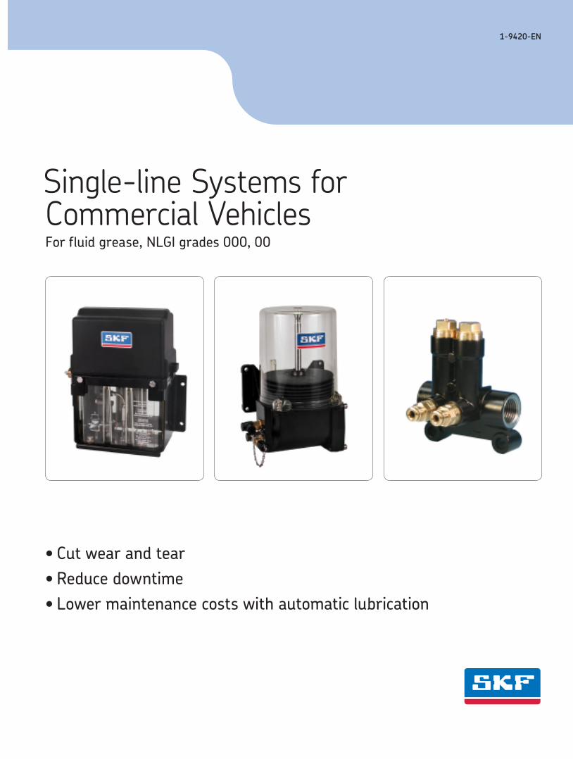
Single-line Systems for Commercial VehiclesFor fluid grease, NLGI grades 000, 00
• Cut wear and tear• Reduce downtime• Lower maintenance costs with automatic lubrication
Single-line Systems for Commercial Vehicles for grease, NLGI grades 000, 00
2 1-9420-EN
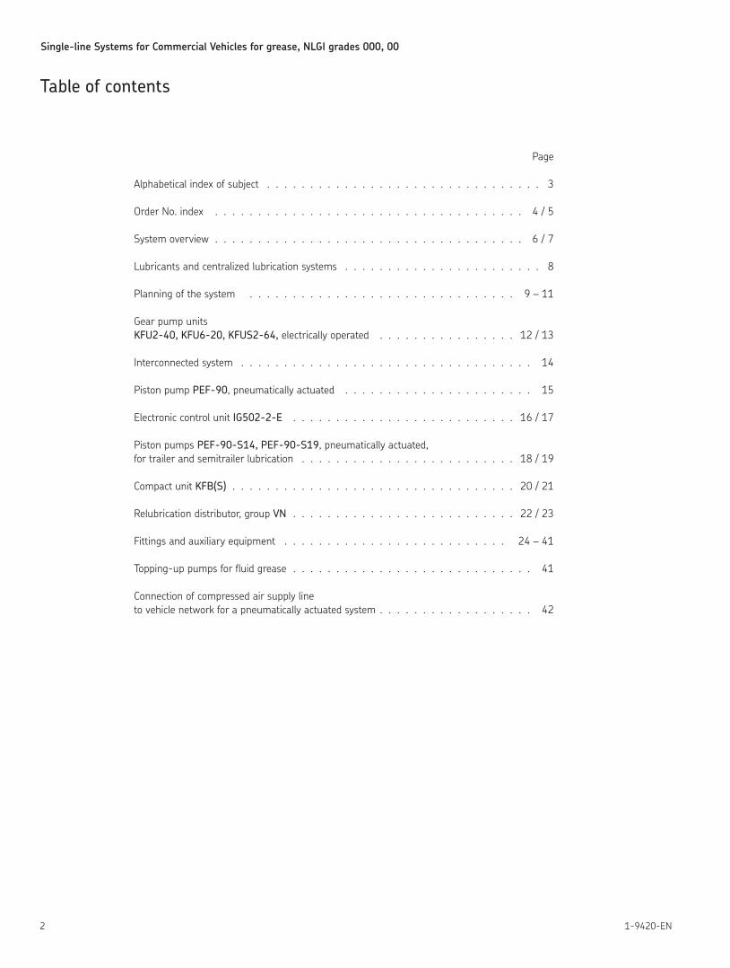
Page
Alphabetical index of subject 3
Order No index 4 / 5
System overview 6 / 7
Lubricants and centralized lubrication systems 8
Planning of the system 9 – 11
Gear pump units KFU2-40, KFU6-20, KFUS2-64, electrically operated 12 / 13
Interconnected system 14
Piston pump PEF-90, pneumatically actuated 15
Electronic control unit IG502-2-E 16 / 17
Piston pumps PEF-90-S14, PEF-90-S19, pneumatically actuated, for trailer and semitrailer lubrication 18 / 19
Compact unit KFB(S) 20 / 21
Relubrication distributor, group VN 22 / 23
Fittings and auxiliary equipment 24 – 41
Topping-up pumps for fluid grease 41
Connection of compressed air supply line to vehicle network for a pneumatically actuated system 42
Table of contents
Single-line Systems for Commercial Vehicles for grease, NLGI grades 000, 00
31-9420-EN
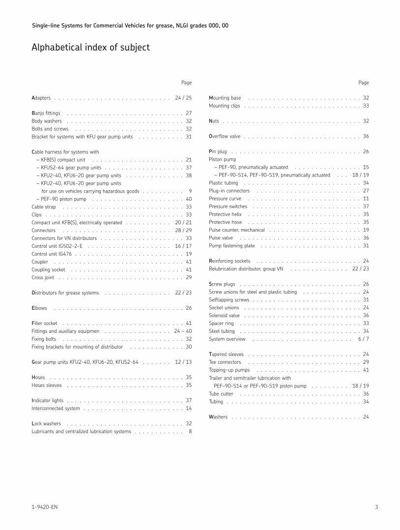
Page
Adapters 24 / 25
Banjo fittings 27 Body washers 32 Bolts and screws 32 Bracket for systems with KFU gear pump units 31
Cable harness for systems with – KFB(S) compact unit 21 – KFUS2-64 gear pump units 37 – KFU2-40, KFU6-20 gear pump units 38 – KFU2-40, KFU6-20 gear pump units for use on vehicles carrying hazardous goods 9 – PEF-90 piston pump 40 Cable strap 33 Clips 33 Compact unit KFB(S), electrically operated 20 / 21 Connectors 28 / 29 Connectors for VN distributors 33 Control unit IG502-2-E 16 / 17 Control unit IG476 19 Coupler 41 Coupling socket 41 Cross joint 29
Distributors for grease systems 22 / 23
Elbows 26
Filler socket 41 Fittings and auxiliary equipmen 24 – 40 Fixing bolts 32 Fixing brackets for mounting of distributor 30
Gear pump units KFU2-40, KFU6-20, KFUS2-64 12 / 13
Hoses 35 Hoses sleeves 35
Indicator lights 37 Interconnected system 14
Lock washers 32 Lubricants and centralized lubrication systems 8
Page
Mounting base 32 Mounting clips 33
Nuts 32
Overflow valve 36
Pin plug 26 Piston pump – PEF-90, pneumatically actuated 15 – PEF-90-S14, PEF-90-S19, pneumatically actuated 18 / 19 Plastic tubing 34 Plug-in connectors 27 Pressure curve 11 Pressure switches 37 Protective helix 35 Protective hose 35 Pulse counter, mechanical 19 Pulse valve 36 Pump fastening plate 31
Reinforcing sockets 24 Relubrication distributor, group VN 22 / 23
Screw plugs 26 Screw unions for steel and plastic tubing 24 Selftapping screws 31 Socket unions 24 Solenoid valve 36 Spacer ring 33 Steel tubing 34 System overview 6 / 7
Tapered sleeves 24 Tee connectors 29 Topping-up pumps 41Trailer and semitrailer lubrication with PEF-90-S14 or PEF-90-S19 piston pump 18 / 19 Tube cutter 36 Tubing 34
Washers 24
Alphabetical index of subject
Single-line Systems for Commercial Vehicles for grease, NLGI grades 000, 00
4 1-9420-EN
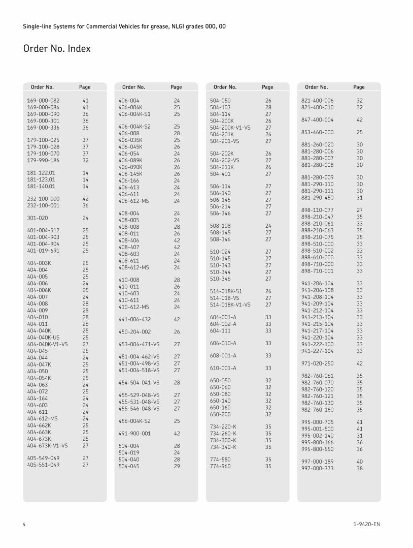
169-000-082 41 169-000-084 41 169-000-090 36 169-000-301 36 169-000-336 36
179-100-025 37 179-100-028 37 179-100-070 37 179-990-186 32
181-122 01 14 181-123 01 14 181-140 01 14
232-100-000 42 232-100-001 36
301-020 24
401-004-512 25 401-004-903 25 401-004-904 25 401-019-691 25
404-003K 25 404-004 25 404-005 25 404-006 24 404-006K 25 404-007 24 404-008 28 404-009 28 404-010 28 404-011 26 404-040K 25 404-040K-US 25 404-040K-V1-VS 27 404-045 25 404-044 24 404-047K 25 404-050 25 404-054K 25 404-063 24 404-072 25 404-164 24 404-603 24 404-611 24 404-612-MS 24 404-662K 25 404-663K 25 404-673K 25 404-673K-V1-VS 27
405-549-049 27 405-551-049 27
406-004 24 406-004K 25 406-004K-S1 25
406-004K-S2 25 406-008 28 406-035K 25 406-045K 26 406-054 24 406-089K 26 406-090K 26 406-145K 26 406-166 24 406-613 24 406-611 24 406-612-MS 24
408-004 24 408-005 24 408-008 28 408-011 26 408-406 42 408-407 42 408-603 24 408-611 24 408-612-MS 24
410-008 28 410-011 26 410-603 24 410-611 24 410-612-MS 24
441-006-432 42
450-204-002 26
453-004-471-VS 27
451-004-462-VS 27 451-004-498-VS 27 451-004-518-VS 27
454-504-041-VS 28
455-529-048-VS 27 455-531-048-VS 27 455-546-048-VS 27
456-004K-S2 25
491-900-001 42
504-004 28 504-019 24 504-040 28 504-045 29
504-050 26 504-103 28 504-114 27 504-200K 26 504-200K-V1-VS 27 504-201K 26 504-201-VS 27
504-202K 26 504-202-VS 27 504-211K 26 504-401 27
506-114 27 506-140 27 506-145 27 506-214 27 506-346 27
508-108 24 508-145 27 508-346 27
510-024 27 510-145 27 510-343 27 510-344 27 510-346 27
514-018K-S1 26 514-018-VS 27 514-018K-V1-VS 27
604-001-A 33 604-002-A 33 604-111 33
606-010-A 33
608-001-A 33
610-001-A 33
650-050 32 650-060 32 650-080 32 650-140 32 650-160 32 650-200 32
734-220-K 35 734-260-K 35 734-300-K 35 734-340-K 35
774-580 35 774-960 35
821-400-006 32 821-400-010 32
847-400-004 42
853-460-000 25
881-260-020 30 881-280-006 30 881-280-007 30 881-280-008 30
881-280-009 30 881-290-110 30 881-290-111 30 881-290-450 31
898-110-077 27 898-210-047 35 898-210-061 33 898-210-063 35 898-210-075 35 898-510-000 33 898-510-002 33 898-610-000 33 898-710-000 33 898-710-001 33
941-206-104 33 941-206-108 33 941-208-104 33 941-209-104 33 941-212-104 33 941-213-104 33 941-215-104 33 941-217-104 33 941-220-104 33 941-222-100 33 941-227-104 33
971-020-250 42
982-760-061 35 982-760-070 35 982-760-120 35 982-760-121 35 982-760-130 35 982-760-160 35
995-000-705 41 995-001-500 41 995-002-140 31 995-800-166 36 995-800-550 36
997-000-189 40 997-000-373 38
Order No. Index
Order No. Page Order No. Page Order No. Page Order No. Page
Single-line Systems for Commercial Vehicles for grease, NLGI grades 000, 00
51-9420-EN
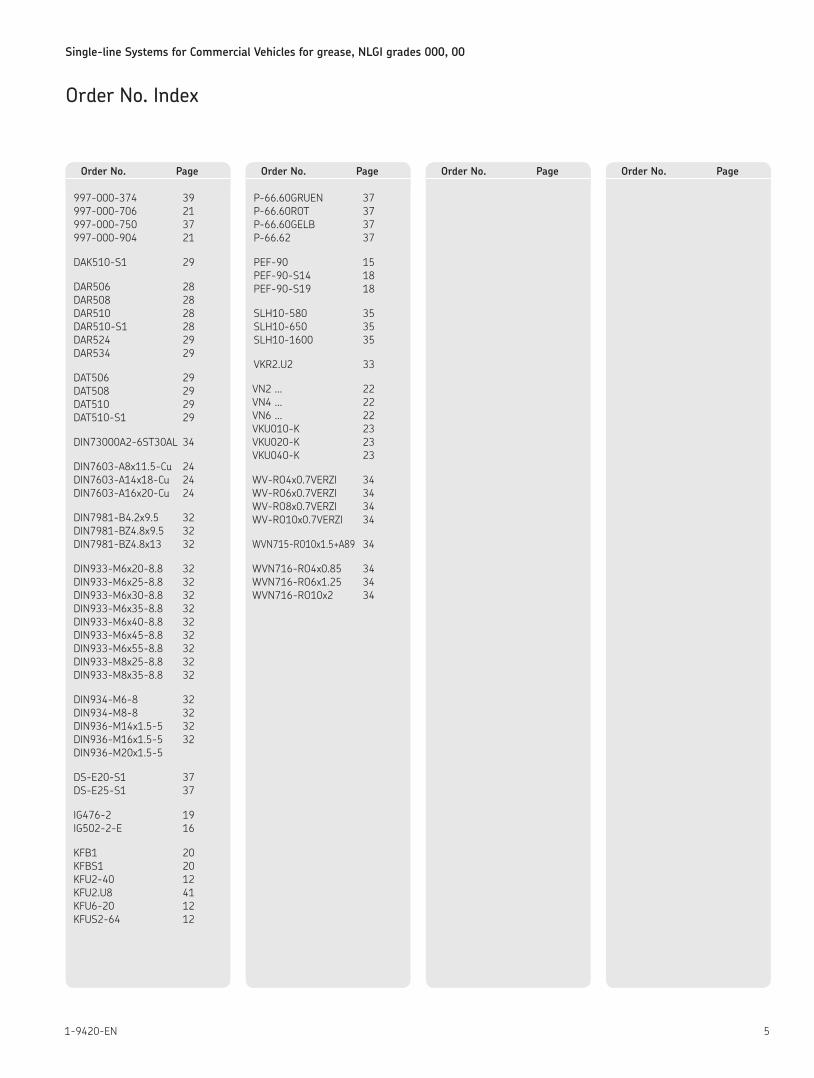
997-000-374 39 997-000-706 21 997-000-750 37 997-000-904 21
DAK510-S1 29
DAR506 28 DAR508 28 DAR510 28 DAR510-S1 28 DAR524 29 DAR534 29
DAT506 29 DAT508 29 DAT510 29 DAT510-S1 29
DIN73000A2-6ST30AL 34
DIN7603-A8x11 5-Cu 24 DIN7603-A14x18-Cu 24 DIN7603-A16x20-Cu 24
DIN7981-B4 2x9 5 32 DIN7981-BZ4 8x9 5 32 DIN7981-BZ4 8x13 32
DIN933-M6x20-8 8 32 DIN933-M6x25-8 8 32 DIN933-M6x30-8 8 32 DIN933-M6x35-8 8 32 DIN933-M6x40-8 8 32 DIN933-M6x45-8 8 32 DIN933-M6x55-8 8 32 DIN933-M8x25-8 8 32 DIN933-M8x35-8 8 32
DIN934-M6-8 32 DIN934-M8-8 32 DIN936-M14x1 5-5 32 DIN936-M16x1 5-5 32 DIN936-M20x1 5-5
DS-E20-S1 37 DS-E25-S1 37
IG476-2 19 IG502-2-E 16
KFB1 20 KFBS1 20 KFU2-40 12 KFU2 U8 41 KFU6-20 12 KFUS2-64 12
P-66 60GRUEN 37 P-66 60ROT 37 P-66 60GELB 37 P-66 62 37
PEF-90 15 PEF-90-S14 18 PEF-90-S19 18
SLH10-580 35 SLH10-650 35 SLH10-1600 35
VKR2 U2 33
VN2 22 VN4 22 VN6 22 VKU010-K 23 VKU020-K 23 VKU040-K 23
WV-RO4x0 7VERZI 34 WV-RO6x0 7VERZI 34 WV-RO8x0 7VERZI 34 WV-RO10x0 7VERZI 34
WVN715-RO10x1 5+A89 34
WVN716-RO4x0 85 34 WVN716-RO6x1 25 34 WVN716-RO10x2 34
Order No. Index
Order No. Page Order No. Page Order No. Page Order No. Page
Single-line Systems for Commercial Vehicles for grease, NLGI grades 000, 00
6 1-9420-EN
1) For progressive systems for commercial vehicles up to NLGI grade 2, see leaflet 1-9430-EN2) GGVS = Hazardous Goods Road Ordinance Germany
System overview
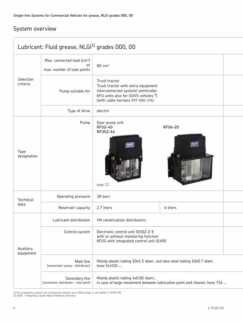
Lubricant: Fluid grease, NLGI1) grades 000, 00
Selection criteria
Type designation
Technical data
Auxiliary equipment
Max. connected load (cm³) or
max. number of lube points
Pump suitable for
Type of drive
80 cm³
Truck tractorTruck tractor with extra equipmentInterconnected system/ semitrailerKFU units also for GGVS vehicles 2) (with cable harness 997-000-374)
electric
Pump Gear pump unit KFU2-40 KFUS2-64
Operating pressure 38 bars
2.7 liters 6 liters
Lubricant distribution
Control system
Main line (connection: pump – distributor)
VN relubrication distributors
Electronic control unit IG502-2-E with or without monitoring function KFUS with integrated control unit IG490
Mainly plastic tubing 10x1.5 diam., but also steel tubing 10x0.7 diam. hose SLH10-...
Mainly plastic tubing 4x0.85 diam.; in case of large movement between lubrication point and chassis: hose 734 …
page 12
Secondary line (connection: distributor – lube point)
KFU6-20
Reservoir capacity
71-9420-EN
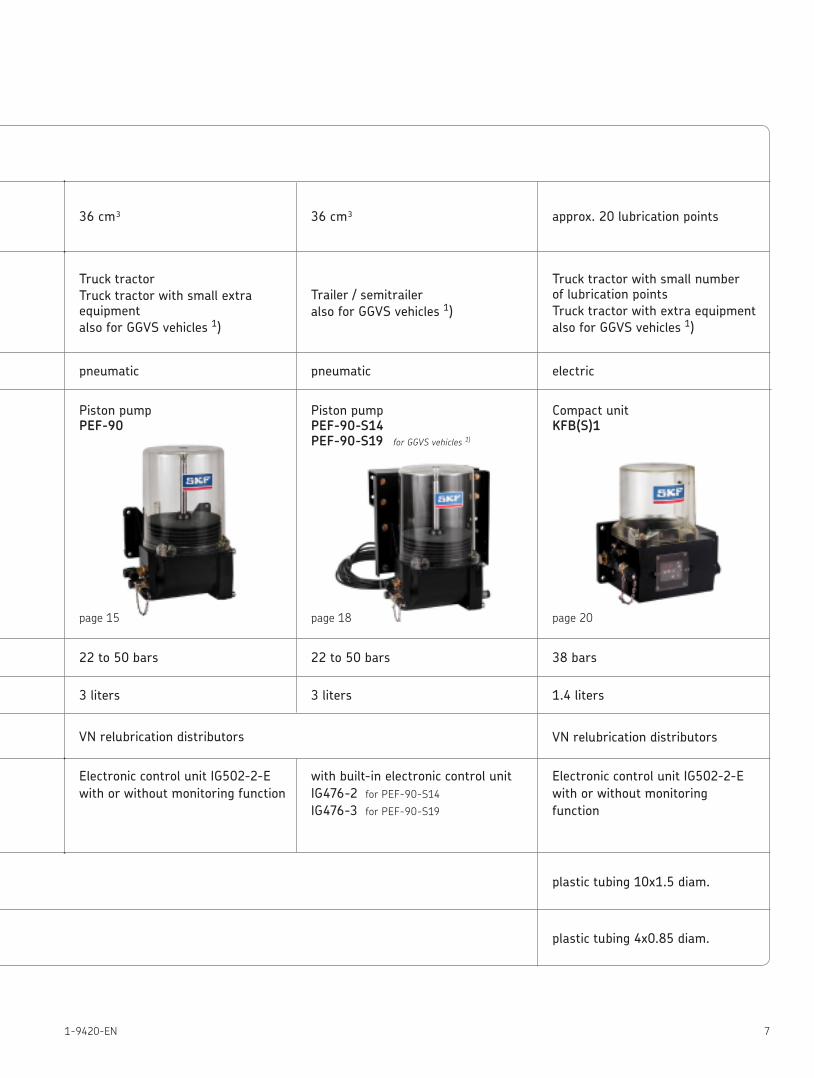
pneumatic pneumatic electric
Mainly plastic tubing 10x1.5 diam., but also steel tubing 10x0.7 diam. hose SLH10-...
Mainly plastic tubing 4x0.85 diam.; in case of large movement between lubrication point and chassis: hose 734 …
22 to 50 bars 22 to 50 bars 38 bars
3 liters 3 liters
VN relubrication distributors VN relubrication distributors
Electronic control unit IG502-2-E with or without monitoring function
36 cm³
Piston pump PEF-90
Piston pump PEF-90-S14 PEF-90-S19 for GGVS vehicles 1)
Compact unit KFB(S)1
page 15 page 18 page 20
36 cm³ approx. 20 lubrication points
Truck tractorTruck tractor with small extra equipmentalso for GGVS vehicles 1)
with built-in electronic control unit IG476-2 for PEF-90-S14 IG476-3 for PEF-90-S19
Electronic control unit IG502-2-E with or without monitoring function
plastic tubing 10x1.5 diam.
plastic tubing 4x0.85 diam.
1.4 liters
Trailer / semitraileralso for GGVS vehicles 1)
Truck tractor with small number of lubrication pointsTruck tractor with extra equipmentalso for GGVS vehicles 1)
Single-line Systems for Commercial Vehicles for grease, NLGI grades 000, 00
8 1-9420-EN
1) Coupler for 1 kg drum, order No. KFU2.U82) Topping-up pumps for 25 kg drum, order No. 169-000-082 and
169-000-084
3) Filler bend for pumps with screw cap, order No. 169-000-037
Centralized lubrication systems may only be used for their intended purpose Centralized lubrication systems can normally be operated with the lubricants listed in the system’s documentation as long as the latter comply with the respective consistency classes and viscosity limits within the indicated temperature range It is possible for the demands on a lubrication system’s configuration to vary concerning the lubricant and the use to which the installation is put
Given the already high “apparent viscosity”, we advise against the use of grease conforming to NLGI Grade 0 since it is possible for fun-damental properties related to delivery of the lubricant to deteriorate considerably, particularly at low ambient temperatures If, nevertheless, a lubricant conforming to NLGI Grade 0 is required, we recommend that its properties be checked to confirm they are adequate
Suitable LubricantsThe lubricants must be suitable for the lubrication of bearings under the ambient conditions to be expected in operation Our experience shows that suiteable lubricants are available from every well-known manufacturer Please contact the supplier when you choose a lubricant SKF Lubrication Systems offers to test the deliverability of a selected lubricant in the event of doubt Lubricants that meet the identical specifications of SKF Lubrication Systems Germany AG, Daimler AG and MAN AG match each other in terms of the parameters applying to their deliverability
A corresponding lubricant can also be purchased from SKF Lubrication Systems Germany AG in 1 kg and 25 kg drums
1 kg drum, Order No. FL1-000 1) 3)
25 kg drum, Order No. FL25-000 2)
Biodegradable types of grease available from SKF Lubrication Systems Germany AG can also be used in centralized lubrication systems
1 kg drum, Order No. FL1-000BIO 1) 25 kg drum, Order No. FL25-000BIO 2)
To assure reliable operation of the centralized lubrication system, always pay attention to cleanliness when topping up lubricant Dirt will lead to malfunctions in a centralized lubrication system and to destruction of the friction points
Lubricants and Centralized Lubrication Systems
ARAL AGAutol-Werke GmbHAVIA Mineralöl Axel ChristiernssonBP Oil Deutschland GmbHCalypsolCastrol Ltd , EnglandDEA
Deutsche Shell GmbHELFEssoFINAGeorg Oest MineralölwerkeMobil Schmierstoff GmbHOptimolÖMV GmbH
Reiner Chemische Fabrik GmbHRHENUSWilhelm Reiners GmbH & Co Siebert GmbHTexacoVeedol Int Ltd , EnglandWinterahall AGZeller+Gmelin GmbH & Co
Lubricant manufacturers who are known to sell appropriate lubricants:
See important product usage information on the back cover
Single-line Systems for Commercial Vehicles for grease, NLGI grades 000, 00
91-9420-EN
Systems for grease, NLGI grades 000, 00
• Electrically operated gear pump units KFU / KFUS
• Pneumatically actuated piston pump PEF-90
• Electrically operated piston pump KFB(S)1
1. Planning and installationa) Determination of number of lubrication points
All friction points of the chassis and any body units, with the exception of the universal joints of the cardan shaft
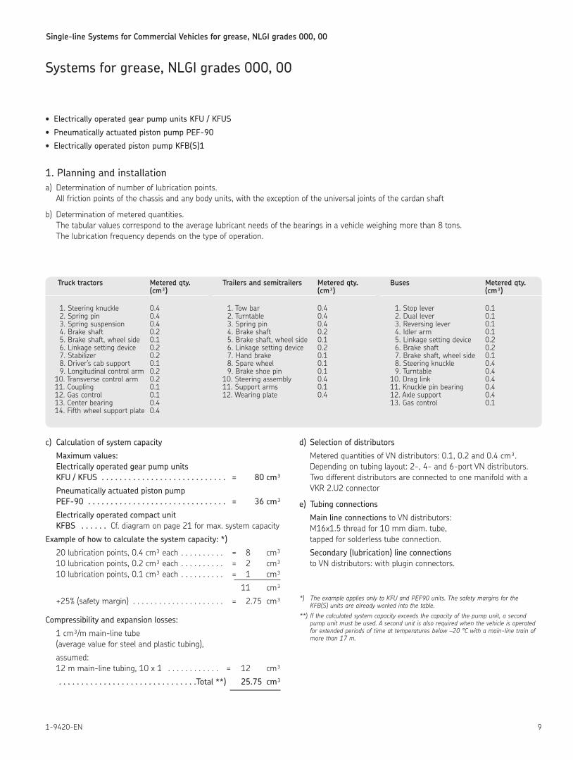
b) Determination of metered quantities The tabular values correspond to the average lubricant needs of the bearings in a vehicle weighing more than 8 tons The lubrication frequency depends on the type of operation
Truck tractors Metered qty. (cm³)
1 Steering knuckle 0 4 2 Spring pin 0 4 3 Spring suspension 0 4 4 Brake shaft 0 2 5 Brake shaft, wheel side 0 1 6 Linkage setting device 0 2 7 Stabilizer 0 2 8 Driver’s cab support 0 1 9 Longitudinal control arm 0 2 10 Transverse control arm 0 2 11 Coupling 0 1 12 Gas control 0 1 13 Center bearing 0 4 14 Fifth wheel support plate 0 4
Trailers and semitrailers Metered qty. (cm³)
1 Tow bar 0 4 2 Turntable 0 4 3 Spring pin 0 4 4 Brake shaft 0 2 5 Brake shaft, wheel side 0 1 6 Linkage setting device 0 2 7 Hand brake 0 1 8 Spare wheel 0 1 9 Brake shoe pin 0 1 10 Steering assembly 0 4 11 Support arms 0 1 12 Wearing plate 0 4
Buses Metered qty. (cm³)
1 Stop lever 0 1 2 Dual lever 0 1 3 Reversing lever 0 1 4 Idler arm 0 1 5 Linkage setting device 0 2 6 Brake shaft 0 2 7 Brake shaft, wheel side 0 1 8 Steering knuckle 0 4 9 Turntable 0 4 10 Drag link 0 4 11 Knuckle pin bearing 0 4 12 Axle support 0 4 13 Gas control 0 1
c) Calculation of system capacity
Maximum values: Electrically operated gear pump units KFU / KFUS . . . . . . . . . . . . . . . . . . . . . . . . . . . . = 80 cm³
Pneumatically actuated piston pump PEF-90 . . . . . . . . . . . . . . . . . . . . . . . . . . . . . . . = 36 cm³
Electrically operated compact unit KFBS . . . . . . Cf diagram on page 21 for max system capacity
Example of how to calculate the system capacity: *)
20 lubrication points, 0 4 cm³ each = 8 cm³ 10 lubrication points, 0 2 cm³ each = 2 cm³ 10 lubrication points, 0 1 cm³ each = 1 cm³
11 cm³
+25% (safety margin) = 2 75 cm³
Compressibility and expansion losses:
1 cm³/m main-line tube (average value for steel and plastic tubing),
assumed: 12 m main-line tubing, 10 x 1 = 12 cm³
. . . . . . . . . . . . . . . . . . . . . . . . . . . . . . .Total **) 25.75 cm³
d) Selection of distributors
Metered quantities of VN distributors: 0 1, 0 2 and 0 4 cm³ Depending on tubing layout: 2-, 4- and 6-port VN distributors Two different distributors are connected to one manifold with a VKR 2 U2 connector
e) Tubing connections
Main line connections to VN distributors: M16x1 5 thread for 10 mm diam tube, tapped for solderless tube connection
Secondary (lubrication) line connections to VN distributors: with plugin connectors
*) The example applies only to KFU and PEF90 units. The safety margins for the KFB(S) units are already worked into the table.
**) If the calculated system capacity exceeds the capacity of the pump unit, a second pump unit must be used. A second unit is also required when the vehicle is operated for extended periods of time at temperatures below –20 °C with a main-line train of more than 17 m.
Single-line Systems for Commercial Vehicles for grease, NLGI grades 000, 00
10 1-9420-EN
f) Installation (Detailed installation instructions are available on request )
This information is supposed to be a guide line and aid for the fitter It will enable him to install the equipment on vehicles even if there are no tubing layouts available, or only incomplete ones
For the prevalent, standard types of commercial vehicles, we have prepared tubing layouts that show how the instal-lations are supposed to be done. If required, these layouts will be mailed free of charge
Additional superstructures and special vehicles can be outfitted on the basis of these layouts
The preassembled VN distributors for standard systems are supplied with a preset metered quantity, but they can be changed to another quantity of lubricant if necessary
Install the VN distributors at suitable loca-tions on the vehicle and connect to the tubing
Max. length of the secondary lines is 6 m (connection: distributor – lubrication point)
Tighten the socket unions, but do not overtighten (maximum of 1 1/2 turns) The tapered sleeves and tubing are slightly deformed when tightened, thus offering no resistance as a fixing bolt would when tightened
Attention must be paid to the following when installing the secondary lines:
– Steering lock angle, sagging, chafing spots.
– Keep away from heat sources.
Install the pump and control unit at a suitable place
Connect hoses and make electrical connections
Some installation hints:
– Use the existing holes drilled in the chassis and in other vehicle parts for the installation
– Span large boreholes with body washers
– Lay 4 x 0 85 plastic tubing (as per WVN716, flexible) between distributors and lubrication points
– Use 734 -K hose lines to connect nonstationary lubrication points and lubrication points that are subject to heavy mechanical stress and strain
– The compressed air for the PEF-90 pneumatically actuated pump must be taken from a line for auxiliary loads The regulations of the german TÜV (Technical Control Board) must be observed
– The pertinent Hazardous Goods Road Ordinance Germany (GGVS) must be observed in the case of tank trucks and other vehicles carrying hazardous goods.
The following pump unit can be used: electrically operated gear pump units KFU2-40, KFU6-20 in conjunction with cable harness 997-000-374; compact units KFB(S) in conjunction with cable harness 997-000-630 or 997-000-650
Furthermore, the pressure switch line must likewise be laid in corrugated tubing
2. Operation and maintenance In the case of automatically controlled
systems, with the exception of KFB(S) compact units, the indicator light goes on for about 3 seconds every time the ignition is switched on (See 3 a for mal-functions of indicator light )
For the most part, maintenance is limited to topping up with clean lubricantwhen necessary
All tube connections should be checked for a tight fit when the vehicle is inspected
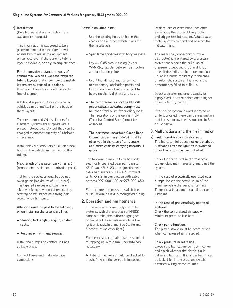
Replace torn or worn hose lines after eliminating the cause of the problem, and trigger test lubrication Actuate auto-matic systems by hand and observe the indicator light
The main line (connection: pump – distributor) is monitored by a pressure switch that reports the build-up of pressure Exception: KFBS and KFUS units If the indicator light does not light up, or if it burns constantly in the case of automatic systems, this means the pressure has failed to build up
Select a smaller metered quantity for highly overlubricated points and a higher quantity for dry points
If the entire system is overlubricated or underlubricated, there can be malfunction: in this case, follow the instructions in 3 b or 3 c below
3. Malfunctions and their eliminationa) Fault indication by indicator light.
The indicator light does not go out about 3 seconds after the ignition is switched on or the motor has been started.
Check lubricant level in the reservoir; top up lubricant if necessary and bleed the system
In the case of electrically operated gear pumps, loosen the screw union of the main line while the pump is running There must be a continuous discharge of lubricant
In the case of pneumatically operated systems: Check the compressed air supply Minimum pressure is 6 bars
Check pump function. The piston stroke must be heard or felt when compressed air is applied
Check pressure in main line. Loosen the lubrication-point connection and check whether the distributor is delivering lubricant If it is, the fault must be looked for in the pressure switch, electrical wiring or control unit
Single-line Systems for Commercial Vehicles for grease, NLGI grades 000, 00
111-9420-EN
Please note: The distributor will not feed lubricant until the main line is relieved of pressure again It is therefore called a “relubrication distributor”
Check electrical connections: Is power available? Are all terminals tight? Check the indicator light, solenoid valve, pressure switch and control unit
Main line connections, main hose lines in particular, must be checked for leakage Then check whether the pump valves are dirty
b) Entire system insufficiently lubricated. Install a pressure gauge in the main line and check the pressure build-up and relief Min pressure build-up is 30 bars.
A maximum residual pressure of 1 bar may remain after the pressure is relieved (measured at pump‘s outlet port)
c) Entire system is overlubricated. Check setting of control unit and increase interval time if necessary
d) Individual lubrication points are over-lubricated or underlubricated. Change metered quantity
e) Distributor faults. Replace distributors
Please note!
A high level of cleanliness must be main-tained when doing any work on the system, es pecially when replacing metering nipples on distributors Dirt in the system causes malfunctions
Never use trichloroethylene, perchloro-ethylene or similar liquids aggressive to Perbunan when cleaning centralized lubri-cation systems Suitable cleaning agents are petroleum ether or kerosene
Pressure curve in main line in the case of systems with VN relubrication distributors
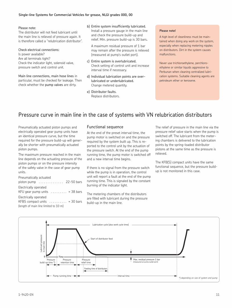
Pneumatically actuated piston pumps and electrically operated gear pump units have an identical pressure curve, but the time required for the pressure build-up will gener-ally be shorter with pneumatically actuated piston pumps
The maximum pressure reached in the main line depends on the actuating pressure of the piston pumps or on the pressure intensity of the safety valve in the case of gear pump units
Pneumatically actuated piston pump 22-50 bars
Electrically operated KFU gear pump units ≈ 38 bars
Electrically operated KFBS compact units ≈ 30 bars(length of main line limited to 10 m)
Functional sequenceAt the end of the preset interval time, the pump motor is switched on and the pressure required by the system built up This is re-ported to the control unit by the actuation of the pressure switch At the end of the pump running time, the pump motor is switched off and a new interval time begins
If there is no signal from the pressure switch while the pump is in operation, the control unit will report a fault at the end of the pump running time This is signaled by the constant burning of the indicator light
The metering chambers of the distributors are filled with lubricant during the pressure build-up in the main line
The relief of pressure in the main line via the pressure relief valve starts when the pump is switched off The lubricant from the meter-ing chambers is delivered to the lubrication points by the spring-loaded distributor pistons at the same time as the pressure is relieved
The KFB(S) compact units have the same functional sequence, but the pressure build-up is not monitored in this case
0
Lubrication cycle (also work cycle time)
Start of distributor feed
Time
Lubr
icant
pre
ssur
ein
mai
n lin
e
Pressurebuild-up time *)
Pressure retention time
Pressurerelief time
Feeding time of distributors
Interval time
Max. residual pressure 1 bar(measured at pump outlet port)
Pump running time*) depending on size of system and pump
Single-line Systems for Commercial Vehicles for grease, NLGI grades 000, 00
12 1-9420-EN
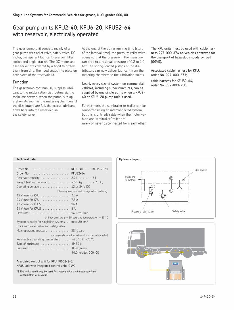
Gear pump units KFU2-40, KFU6-20, KFUS2-64 with reservoir, electrically operated
Technical data
Order No. . . . . . . . . . . . . . . . . . . . . . . . KFU2-40 . . . . KFU6-20 *)Order No. . . . . . . . . . . . . . . . . . . . . . . . KFUS2-64Reservoir capacity 2 7 l 6 lWeight (without lubricant) ≈ 5 5 kg ≈ 7 3 kgOperating voltage 12 or 24 V DC
Please quote required voltage when ordering
12 V fuse for KFU 7 5 A24 V fuse for KFU 7 5 A12 V fuse for KFUS 16 A24 V fuse for KFUS 8 AFlow rate 140 cm³/min
at back pressure p = 38 bars and temperature t = 25 °C
System capacity for singleline systems max 80 cm³Units with relief valve and safety valveMax operating pressure 38 +2
-3 bars(corresponds to actual value of built-in safety valve)
Permissible operating temperature –25 °C to +75 °CType of enclosure IP 59 kLubricant fluid grease, NLGI grades 000, 00
Associated control unit for KFU: IG502-2-E, KFUS unit with integrated control unit: IG490
*)Thisunitshouldonlybeusedforsystemswithaminimumlubricantconsumptionof6l/year.
The gear pump unit consists mainly of a gear pump with relief valve, safety valve, DC motor, transparent lubricant reservoir, filler socket and angle bracket The DC motor and filler socket are covered by a hood to protect them from dirt The hood snaps into place on both sides of the reservoir lid
FunctionThe gear pump continuously supplies lubri-cant to the relubrication distributors via the main line network when the pump is in op-eration As soon as the metering chambers of the distributors are full, the excess lubricant flows back into the reservoir via the safety valve
At the end of the pump running time (start of the interval time), the pressure relief valve opens so that the pressure in the main line can drop to a residual pressure of 0 2 to 1 0 bar The spring-loaded pistons of the dis-tributors can now deliver lubricant from the metering chambers to the lubrication points
Nearly every size of system on commercial vehicles, including superstructures, can be supplied by one single pump when a KFU2-40 or KFU6-20 pump unit is used.
Furthermore, the semitrailer or trailer can be connected using an interconnected system, but this is only advisable when the motor ve-hicle and semitrailer/trailer are rarely or never disconnected from each other
The KFU units must be used with cable har-ness 997-000-374 on vehicles approved for the transport of hazardous goods by road (GGVS).
Associated cable harness for KFU, order No. 997-000-373;
cable harness for KFUS2-64, order No. 997-000-750.
M
Hydraulic layout
Filler socket
Safety valvePressure relief valve
Main line to system
Single-line Systems for Commercial Vehicles for grease, NLGI grades 000, 00
131-9420-EN
+ -
325343
910
075
.5
184
211.
5
53
105.5
~ 36
4
min
max
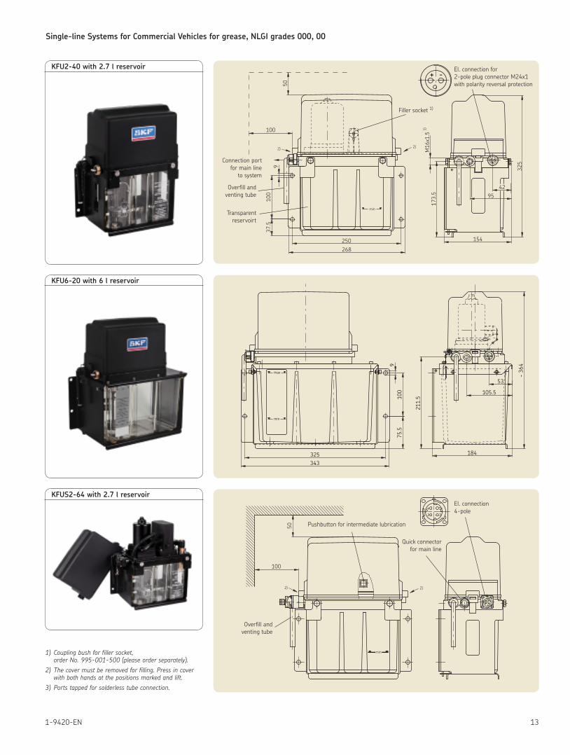
KFU2-40 with 2.7 l reservoir
KFU6-20 with 6 l reservoir
KFUS2-64 with 2.7 l reservoir
1) Coupling bush for filler socket, order No. 995-001-500 (please order separately).
2) The cover must be removed for filling. Press in cover with both hands at the positions marked and lift.
3) Ports tapped for solderless tube connection.
min
2)
50
100
9100
37.5
250
268
2)
173.5
M16x1.5
3)
154
4295
325
+ -
+ -
Connection port for main line
to system
Overfill and venting tube
Transparent reservoirt
Filler socket 1)
El connection for 2-pole plug connector M24x1 with polarity reversal protection
50
100
4
2
1
3
2) 2)
min
Pushbutton for intermediate lubrication
Quick connector for main line
Overfill and venting tube
El connection 4-pole
2
4
3
1
Single-line Systems for Commercial Vehicles for grease, NLGI grades 000, 00
14 1-9420-EN
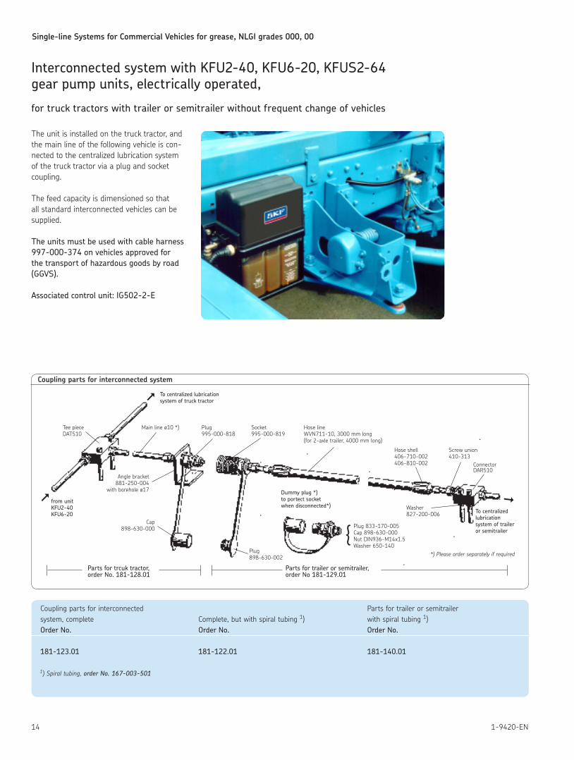
Interconnected system with KFU2-40, KFU6-20, KFUS2-64 gear pump units, electrically operated,
for truck tractors with trailer or semitrailer without frequent change of vehicles
The unit is installed on the truck tractor, and the main line of the following vehicle is con-nected to the centralized lubrication system of the truck tractor via a plug and socket coupling
The feed capacity is dimensioned so that all standard interconnected vehicles can be supplied
The units must be used with cable harness 997-000-374 on vehicles approved for the transport of hazardous goods by road (GGVS).
Associated control unit: IG502-2-E
Coupling parts for interconnected system
To centralized lubrication system of truck tractorÞ
Þ
Tee piece Main line ø10 *) Plug Socket Hose line DAT510 995-000-818 995-000-819 WVN711-10, 3000 mm long (for 2-axle trailer, 4000 mm long)
Hose shell Screw union 406-710-002 410-313 406-810-002 Connector
DAR510Angle bracket
881-250-004 with borehole ø17
from unitKFU2-40KFU6-20
Cap898-630-000
Plug898-630-002
Dummy plug *)to portect socket when disconnected*) Washer
827-200-006 To centralized lubrication system of trailer or semitrailer
Plug 833-170-005Cap 898-630-000Nut DIN936-M14x1 5Washer 650-140
{
Þ
Parts for trcuk tractor, Parts for trailer or semitrailer,order No. 181-128.01 order No 181-129.01
Coupling parts for interconnected Parts for trailer or semitrailersystem, complete Complete, but with spiral tubing 1) with spiral tubing 1) Order No. Order No. Order No.
181-123.01 181-122.01 181-140.01
1) Spiral tubing, orderNo.167-003-501
*) Please order separately if required
Single-line Systems for Commercial Vehicles for grease, NLGI grades 000, 00
151-9420-EN
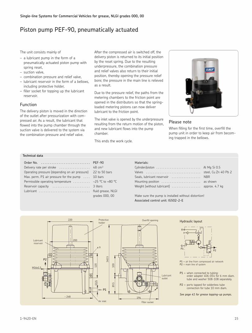
Piston pump PEF-90, pneumatically actuated
The unit consists mainly of
– a lubricant pump in the form of a pneumatically actuated piston pump with spring reset,
– suction valve, – combination pressure and relief valve, – lubricant reservoir in the form of a bellows, including protective holder,
– filler socket for topping up the lubricant reservoir
FunctionThe delivery piston is moved in the direction of the outlet after pressurization with com-pressed air As a result, the lubricant that flowed into the pump chamber through the suction valve is delivered to the system via the combination pressure and relief valve
After the compressed air is switched off, the delivery piston is returned to its initial position by the reset spring Due to the resulting underpressure, the combination pressure and relief valves also return to their initial position, thereby opening the pressure relief bore; the pressure in the main line is relieved as a result
Due to the pressure relief, the paths from the metering chambers to the friction point are opened in the distributors so that the spring-loaded metering pistons can now deliver lubricant to the friction point
The inlet valve is opened by the underpressure resulting from the return motion of the piston, and new lubricant flows into the pump chamber
This ends the work cycle
Please noteWhen filling for the first time, overfill the pump unit in order to keep air from becom-ing trapped in the bellows
Technical data
Order No. . . . . . . . . . . . . . . . . . . . . . . . . . . . . PEF-90Delivery rate per stroke 48 cm³Operating pressure (depending on air pressure) 22 to 50 barsMax perm P1 air pressure for the pump 10 barsPermissible operating temperature –25 °C to +80 °CReservoir capacity 3 liters Lubricant fluid grease, NLGI grades 000, 00
Materials:Cylinder/piston Al Mg Si 0 5Valves steel, Cu Zn 40 Pb 2Seals, lubricant reservoir NBRMounting position as shownWeight (without lubricant) approx 4 7 kg
Make sure the pump is installed without distortion!Associated control unit: IG502-2-E
220
200
~ 248
120
G1/4
M16x1.5
89.5
100
340.
5
194
ø 9
P1
P2
P1P2
R
Lubricant reservoir
Protective holder
Overfill opening
Air inlet Filler socket
Lubricant outlet
Hydraulic layout
P1 = air line from compressed air networkP2 = main line of system
P1 = when connected to tubing: order adapter 406-054 for 6 mm diam tube and washer 508-108 separately
P2 = ports tapped for solderless tube connection for tube 10 mm diam
Seepage41forgreasetopping-uppumps.
Single-line Systems for Commercial Vehicles for grease, NLGI grades 000, 00
16 1-9420-EN
Electronic control unit IG502-2-Efor systems with KFU2-40, KFU6-20 gear pump units or PEF-90 piston pump
Operating and display elementsThe IG502 control units come with an operating and display panel that can be used to check, monitor and, if necessary, readjust the parameters as well as programmed functions
Modes of operationPAUSE (pump OFF) with timer function – programmable from 0.1 to 99.9 h – digital display after invoking: tPA (t = timer, PA = PAUSE)
The PAUSE (the interval between two lube cycles) is determined by a clock cycle (timer) generated by the control system and by the value (in hours) programmed for PAUSE (tPA)
PAUSE (pump OFF) with counter function – programmable from 1 to 999 pulses – digital display after invoking: cPA (c = counter, PA = PAUSE)
The PAUSE (the interval between two lube cycles) is determined by the interval between the time signals arrive at the counter input and by the value programmed for PAUSE (cPA)
CONTACT (pump ON) with timer function – programmable from 1 to 99.9 minutes – digital display after invoking: tCO (t = timer, CO = CONTACT)
The pump running time (CONTACT) is determined by a clock cycle (timer) generated by the control system and by the value (in minutes) programmed for CONTACT (tCO)
Monitoring functionsPS (Pressure Switch) This monitoring function is intended for centralized grease lubrication systems designed for NLGI grades 000, 00, 0 in which the pressure in the main line is monitored Once the monitoring parameter PS has been programmed, the pressure switch installed in the main line is monitored for respective signals while the pump is in operation
CS (Cycle Switch) This monitoring function is intended for centralized grease lubrication systems with progressive feeders in which a piston‘s mo-tion is monitored with a cycle switch
Once the monitoring parameter CS has been set, the cycle switch installed on the progres-sive feeder is monitored for the respective signal while the pump is in operation The respective monitoring parameter selected (PS or CS) is displayed by the light-ing of the corresponding LED in the PAUSE (interval) mode
Without monitoring (OFF)The monitoring can also be switched off (OFF) The control system then works without direct monitoring of the pressure build-up in the main line or without monitoring of the feeder‘s operation The PS or CS LEDs do not light up
Fault displaysThe red FAULT LED shows a group fault signal when it constantly burns The cause of the fault signal is additionally shown on the digital display to help with troubleshooting The following messages are provided for:FPS – pressure build-up fault when monitor-
ing is effected with a pressure switch FCS – cycle switch fault when a progressive
feeder is not working or is blocked (line break)
Special functionsControl units comprising the IG502 group have two electronic counters in which times are permanently stored; they cannot be changed by the user These counters are used to check the opera-tion of the centralized lubrication system and are read out via the LED display
Fault-hours counterThe amount of time a farm or construction machine has been run with a non-function-ing centralized lubrication system (e g with no lubricant in the reservoir) is added up by the fault-hours counter The counter‘s contents are automatically updated and cannot be cleared The current state of the counter can be displayed by in-voking function parameter Fh on the display and operating panel The current value is displayed in hours The counter has a resolution of 0 1 hour, i e the smallest displayable interval amounts to 6 minutes
Elapsed-hours counterThe electronic elapsed-hours counter adds up the time in which power is applied to the control unit The counter‘s contents are automatically up-dated and cannot be cleared The current state of the counter can be displayed by in-voking function parameter Oh on the display and operating panel The current value is displayed in hours The counter has a resolution of 0 1 hour, i e the smallest displayable interval amounts to 6 minutes The units meet the legal requirements of the applicable EC Directives. The unit is EC Type Approved (e1).
ApplicationThe IG502-2-E universal control unit is used to control and monitor centralized lubrication systems on commercial vehicles The control unit‘s functions can be programmed Its housing dimensions, electrical connection and functions are compatible with those of SKF control units currently in use The operating elements are protected by a foil against moisture and dirt The unit has a voltage-independent data memory This is where the configuration data and parameters are stored As a result, the control unit is not dependent on a constant supply of voltage If an external indicator light SL has been installed in the driver‘s cab, it will light up for 3 seconds after the unit is switched on
InstallationThe unit has to be installed in a closed com-partment on the vehicle where it is protected from ambient influences It is fastened in place with straps The IG502-2-E is accommodated in an IP 20 type of enclosure The plug conforms to safety class IP 00 If the control unit is installed in a hard-to-reach place, it is advisable to additionally install an illuminated pushbutton on the dashboard to serve as a fault display and function check
Single-line Systems for Commercial Vehicles for grease, NLGI grades 000, 00
171-9420-EN
Obse
rve
oper
atin
g in
stru
ctio
ns !
Bedi
enun
gsan
leitu
ng b
each
ten
!
80
65±0.8 5.2
7.2
103±
1.2
40±0.8
Z
30
5A137±
1.2
3
8.5±
0.2
2±0.8
PS/C
SM
31
DK/
MK
15
SL
PS/CS
DK
SL 3 sec.
<tpM
ts tp ts <tp tp+tuts tp ts
3 sec.
ts <tp
+15tu
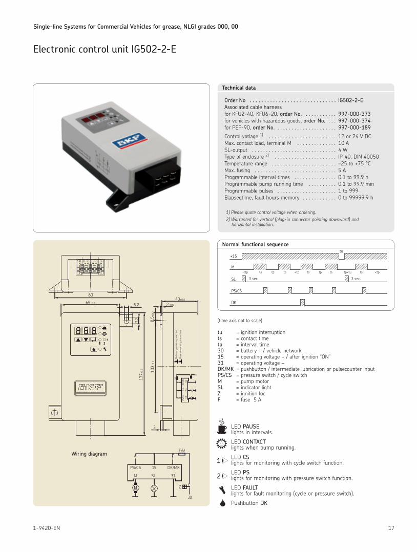
Normal functional sequence
(time axis not to scale)
tu = ignition interruptionts = contact timetp = interval time30 = battery + / vehicle network15 = operating voltage + / after ignition “ON”31 = operating voltage –DK/MK = pushbutton / intermediate lubrication or pulsecounter inputPS/CS = pressure switch / cycle switchM = pump motorSL = indicator lightZ = ignition locF = fuse 5 A
LED PAUSE lights in intervals
LED CONTACT lights when pump running
LED CS lights for monitoring with cycle switch function
LED PS lights for monitoring with pressure switch function
LED FAULT lights for fault monitoring (cycle or pressure switch)
Pushbutton DK
1
2
Technical data
Order No . . . . . . . . . . . . . . . . . . . . . . . . . . . . . . IG502-2-EAssociated cable harness for KFU2-40, KFU6-20, order No. 997-000-373for vehicles with hazardous goods, order No. 997-000-374for PEF-90, order No. 997-000-189
Control votlage 1) 12 or 24 V DCMax contact load, terminal M 10 ASL-output 4 WType of enclosure 2) IP 40, DIN 40050Temperature range –25 to +75 °CMax fusing 5 AProgrammable interval times 0 1 to 99 9 hProgrammable pump running time 0 1 to 99 9 minProgrammable pulses 1 to 999Elapsedtime, fault hours memory 0 to 99999 9 h
1) Please quote control voltage when ordering.2) Warranted for vertical (plug-in connector pointing downward) and
horizontal installation.
Electronic control unit IG502-2-E
DK/MK15PS/CS
SLM 31
Z
30
F=5A
M
Wiring diagram
Single-line Systems for Commercial Vehicles for grease, NLGI grades 000, 00
18 1-9420-EN
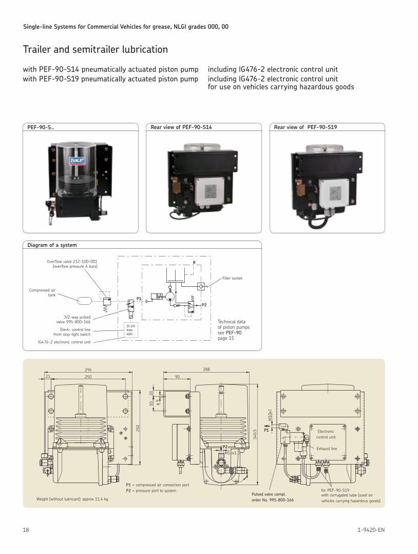
Trailer and semitrailer lubrication
with PEF-90-S14 pneumatically actuated piston pump including IG476-2 electronic control unitwith PEF-90-S19 pneumatically actuated piston pump including IG476-2 electronic control unit for use on vehicles carrying hazardous goods
PEF-90-S.. Rear view of PEF-90-S14 Rear view of PEF-90-S19
P2
P1
23 250
296
250
2050
90
288
ø 9
340.
5
M10
x1
M16x1.5
A
P
Weight (without lubricant): approx 11 4 kg
P1 = compressed air connection port P2 = pressure port to system
Pulsed valve compl. order No. 995-800-166
for PEF-90-S19 with corrugated tube (used on vehicles carrying hazardous goods)
Electronic control unit
Exhaust line
P1P2
R
20-240brakeapplic.
Diagram of a system
Overflow valve 232-100-001 (overflow pressure 6 bars)
Compressed air tank
3/2-way pulsed valve 995-800-166
Electr control line from stop-light switch
IG476-2 electronic control unit
Filler socket
Technical data of piston pumpssee PEF-90 page 15
Single-line Systems for Commercial Vehicles for grease, NLGI grades 000, 00
191-9420-EN
Trailer and semitrailer lubrication
with PEF-90-S14 pneumatically actuated piston pump including IG476-2 electronic control unitwith PEF-90-S19 pneumatically actuated piston pump including IG476-2 electronic control unit for use on vehicles carrying hazardous goods
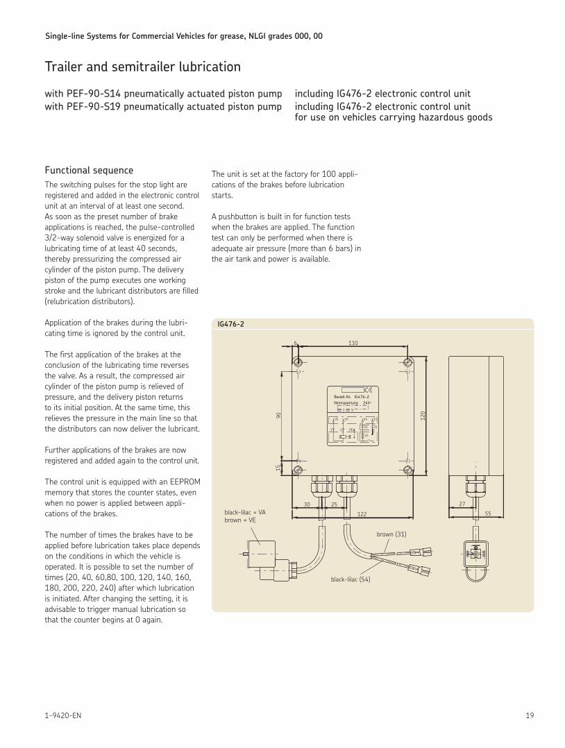
Functional sequence The switching pulses for the stop light are registered and added in the electronic control unit at an interval of at least one second As soon as the preset number of brake applications is reached, the pulse-controlled 3/2-way solenoid valve is energized for a lubricating time of at least 40 seconds, thereby pressurizing the compressed air cylinder of the piston pump The delivery piston of the pump executes one working stroke and the lubricant distributors are filled (relubrication distributors)
Application of the brakes during the lubri-cating time is ignored by the control unit
The first application of the brakes at the conclusion of the lubricating time reverses the valve As a result, the compressed air cylinder of the piston pump is relieved of pressure, and the delivery piston returns to its initial position At the same time, this relieves the pressure in the main line so that the distributors can now deliver the lubricant
Further applications of the brakes are now registered and added again to the control unit
The control unit is equipped with an EEPROM memory that stores the counter states, even when no power is applied between appli-cations of the brakes
The number of times the brakes have to be applied before lubrication takes place depends on the conditions in which the vehicle is operated It is possible to set the number of times (20, 40, 60,80, 100, 120, 140, 160, 180, 200, 220, 240) after which lubrication is initiated After changing the setting, it is advisable to trigger manual lubrication so that the counter begins at 0 again
The unit is set at the factory for 100 appli-cations of the brakes before lubrication starts
A pushbutton is built in for function tests when the brakes are applied The function test can only be performed when there is adequate air pressure (more than 6 bars) in the air tank and power is available
NennspannungBestell-Nr.
1 2 PE
VE VA
IG476-2
2A
54 31
24V-
54 31
6 110
1590 120
30 25
122
27
55
IG476-2
black-lilac = VA brown = VE
black-lilac (54)
brown (31)
Single-line Systems for Commercial Vehicles for grease, NLGI grades 000, 00
20 1-9420-EN
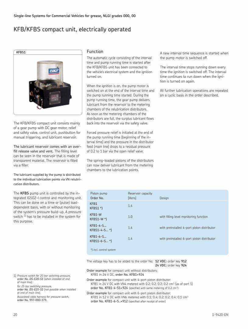
KFB/KFBS compact unit, electrically operated
The KFB/KFBS compact unit consists mainly of a gear pump with DC gear motor, relief and safety valve, control unit, pushbutton for manual triggering, and lubricant reservoir
The lubricant reservoir comes with an over-fill release valve and vent. The filling level can be seen in the reservoir that is made of transparent material The reservoir is filled via a filler
The lubricant supplied by the pump is distributed to the individual lubrication points via VN relubri-cation distributors.
The KFBS pump unit is controlled by the in-tegrated IG502-I control and monitoring unit This can be done on a time or (pulse) load-dependent basis, with or without monitoring of the system‘s pressure build-up A pressure switch 1) has to be installed in the system for this purpose
FunctionThe automatic cycle consisting of the interval time and pump running time is started after the KFB/KFBS unit has been connected to the vehicle’s electrical system and the ignition turned on
When the ignition is on, the pump motor is switched on at the end of the interval time and the pump running time started During the pump running time, the gear pump delivers lubricant from the reservoir to the metering chambers of the relubrication distributors As soon as the metering chambers of the distributors are full, the surplus lubricant flows back into the reservoir via the safety valve
Forced pressure relief is initiated at the end of the pump running time (beginning of the in-terval time) and the pressure in the distributor feed (main line) drops to a residual pressure of 0 2 to 1 bar via the open relief valve
The spring-loaded pistons of the distributors can now deliver lubricant from the metering chambers to the lubrication points
A new interval time sequence is started when the pump motor is switched off
The interval time stops running down every time the ignition is switched off The interval time continues to run down when the igni-tion is turned on again
All further lubrication operations are repeated on a cyclic basis in the order described
Piston pump Reservoir capacity Order No. [liters] Design
KFB1 1 4 KFBS1 *)
KFB1-W 1 0 with filling level monitoring function KFBS1-W *)
KFB1-4-S... 1 4 with preinstalled 4-port piston distributor KFBS1-4-S... *)
KFB1-6-S... 1 4 with preinstalled 6-port piston distributor KFBS1-6-S... *)
*) incl. control system
KFBS1
The voltage key has to be added to the order No: 12 VDC: order key 912 24 VDC: order key 924
Order example for compact unit without distributors: KFB1 in 24 V DC, order No. KFB1+924
Order example for compact unit with 4-port piston distributor: KFB1 in 24 V DC with VN4 metered with 0 2; 0 2; 0 2; 0 2 cm³ (as of port 1) order No. KFB1-4-S1+924 (specified with same metering of 0 2 cm³)
Order example for compact unit with 6-port piston distributor: KFB1 in 12 V DC with VN6 metered with 0 1; 0 4; 0 2; 0 2; 0 4; 0 1 cm³ order No. KFB1-6-S..+912 (specified after receipt of order)
1) Pressure switch for 20 bar switching pressure, orderNo.DS-E20-S1(when installed at end of main line);
for 25 bar switching pressure, orderNo.DS-E25-S1(not possible when installed at end of main line).
Associated cable harness for pressure switch, order No. 997-000-379.
Single-line Systems for Commercial Vehicles for grease, NLGI grades 000, 00
211-9420-EN
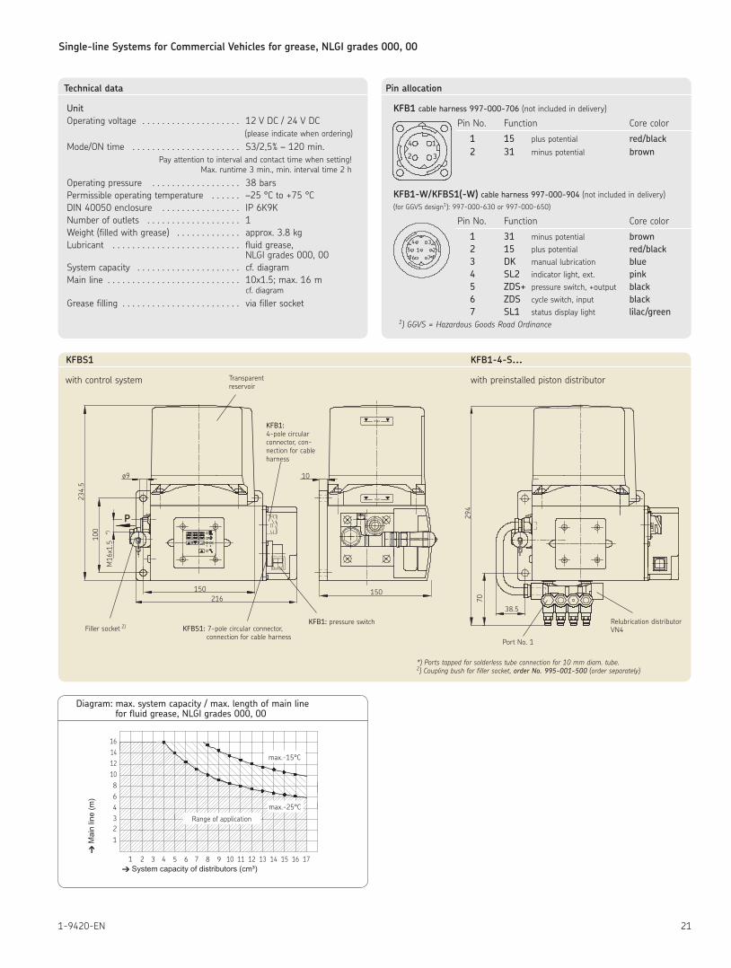
Diagram: max. system capacity / max. length of main line for fluid grease, NLGI grades 000, 00
6
1 2 43
2
1
43
65 7 98
108
1412
16
max.-15°C
max.-25°C
10 11 12 13 14 15 16 17
M
ain
line
(m)
System capacity of distributors (cm³)
Range of application
Technical data
UnitOperating voltage 12 V DC / 24 V DC (please indicate when ordering)
Mode/ON time S3/2,5% – 120 min Pay attention to interval and contact time when setting! Max runtime 3 min , min interval time 2 h
Operating pressure 38 barsPermissible operating temperature –25 °C to +75 °CDIN 40050 enclosure IP 6K9KNumber of outlets 1Weight (filled with grease) approx 3 8 kgLubricant fluid grease, NLGI grades 000, 00 System capacity cf diagramMain line 10x1 5; max 16 m cf diagram
Grease filling via filler socket
Pin allocation
KFB1 cable harness 997-000-706 (not included in delivery)
Pin No Function Core color
1 15 plus potential red/black 2 31 minus potential brown
KFB1-W/KFBS1(-W) cable harness 997-000-904 (not included in delivery) (for GGVS design1): 997-000-630 or 997-000-650)
Pin No Function Core color
1 31 minus potential brown 2 15 plus potential red/black 3 DK manual lubrication blue 4 SL2 indicator light, ext pink 5 ZDS+ pressure switch, +output black 6 ZDS cycle switch, input black 7 SL1 status display light lilac/green
1) GGVS = Hazardous Goods Road Ordinance
4
2
1
3
4 3215
6 7
P
70
38.5
294
max
min
100
234.5
M16x1.5
*)
ø9
216150 150
10
1 2
KFBS1 KFB1-4-S...
with control system with preinstalled piston distributorTransparent reservoir
KFB1: 4-pole circular connector, con-nection for cable harness
Filler socket 2) KFBS1: 7-pole circular connector, connection for cable harness
KFB1: pressure switch
Port No 1
Relubrication distributorVN4
*) Ports tapped for solderless tube connection for 10 mm diam. tube.2) Coupling bush for filler socket, orderNo.995-001-500 (order separately)
Single-line Systems for Commercial Vehicles for grease, NLGI grades 000, 00
22 1-9420-EN
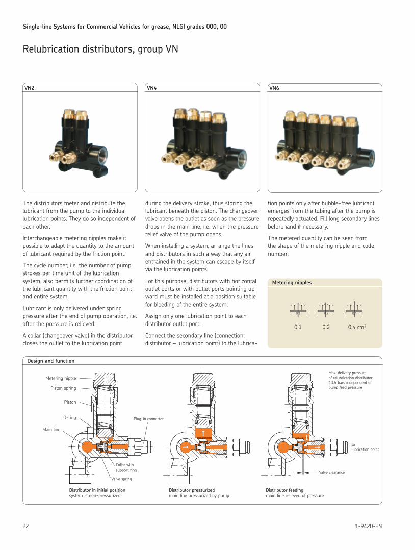
The distributors meter and distribute the lubricant from the pump to the individual lubrication points They do so independent of each other
Interchangeable metering nipples make it possible to adapt the quantity to the amount of lubricant required by the friction point
The cycle number, i e the number of pump strokes per time unit of the lubrication system, also permits further coordination of the lubricant quantity with the friction point and entire system
Lubricant is only delivered under spring pressure after the end of pump operation, i e after the pressure is relieved
A collar (changeover valve) in the distributor closes the outlet to the lubrication point
during the delivery stroke, thus storing the lubricant beneath the piston The changeover valve opens the outlet as soon as the pressure drops in the main line, i e when the pressure relief valve of the pump opens
When installing a system, arrange the lines and distributors in such a way that any air entrained in the system can escape by itself via the lubrication points
For this purpose, distributors with horizontal outlet ports or with outlet ports pointing up-ward must be installed at a position suitable for bleeding of the entire system
Assign only one lubrication point to each distributor outlet port
Connect the secondary line (connection: distributor – lubrication point) to the lubri ca-
tion points only after bubble-free lubricant emerges from the tubing after the pump is repeatedly actuated Fill long secondary lines beforehand if necessary
The metered quantity can be seen from the shape of the metering nipple and code number
0,1 0,2 0,4
Metering nipples
Relubrication distributors, group VN
Design and function
VN2 VN4 VN6
Distributor in initial position Distributor pressurized Distributor feeding system is non-pressurized main line pressurized by pump main line relieved of pressure
Metering nipple
Piston spring
Piston
O-ring
Main line
Plug-in connector
Collar with support ring
Valve springValve clearance
to lubrication point
Max delivery pressure of relubrication distributor13 5 bars independent ofpump feed pressure
0,1 0,2 0,4 cm³
Single-line Systems for Commercial Vehicles for grease, NLGI grades 000, 00
231-9420-EN
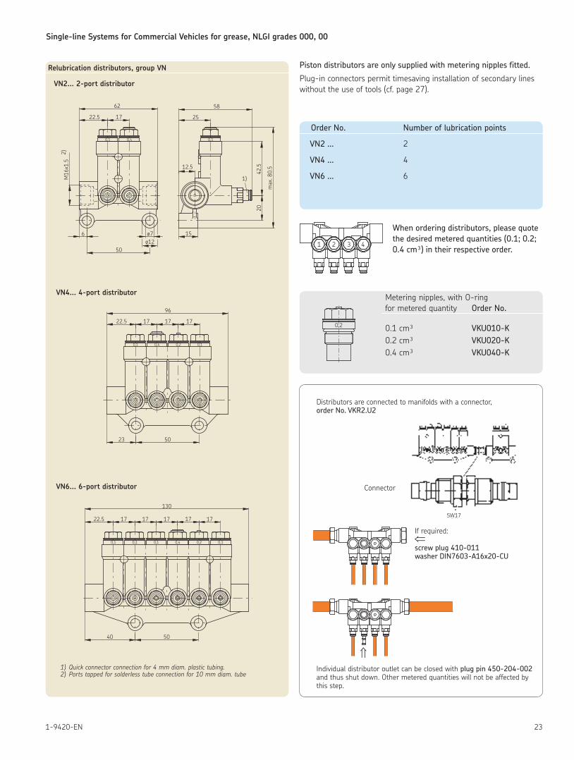
Metering nipples, with O-ringfor metered quantity Order No.
0 1 cm³ VKU010-K 0 2 cm³ VKU020-K 0 4 cm³ VKU040-K
1)
50
M16
x1.5
2)
1722.5
62
15
12.5
25
58
42.5
20
max
. 80.
5
23 50
22.5 17 17 17
96
40 50
1722.5 17 17 17
130
6
17
0,10,10,1 0,4 0,2 0,1
0,1 0,1
0,10,20,40,1
0,4
ø7ø12
Relubrication distributors, group VN
VN2... 2-port distributor
VN4... 4-port distributor
VN6... 6-port distributor
1) Quick connector connection for 4 mm diam. plastic tubing.2) Ports tapped for solderless tube connection for 10 mm diam. tube
Distributors are connected to manifolds with a connector, order No. VKR2.U2
Connector
If required: ⇐ screw plug 410-011 washer DIN7603-A16x20-CU
⇑Individual distributor outlet can be closed with plug pin 450-204-002 and thus shut down Other metered quantities will not be affected by this step
SW17
Piston distributors are only supplied with metering nipples fitted.
Plug-in connectors permit timesaving installation of secondary lines without the use of tools (cf page 27)
When ordering distributors, please quote the desired metered quantities (0.1; 0.2; 0.4 cm³) in their respective order.
Order No. Number of lubrication points
VN2 … 2
VN4 … 4
VN6 … 6
1 2 3 4
0,2
Single-line Systems for Commercial Vehicles for grease, NLGI grades 000, 00
24 1-9420-EN
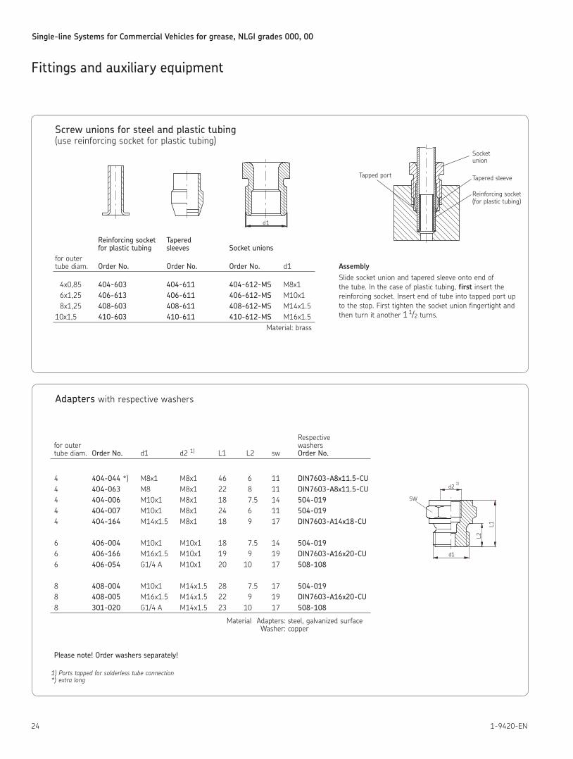
Screw unions for steel and plastic tubing (use reinforcing socket for plastic tubing)
Reinforcing socket Tapered for plastic tubing sleeves Socket unions for outer tube diam Order No. Order No. Order No. d1
4x0,85 404-603 404-611 404-612-MS M8x1 6x1,25 406-613 406-611 406-612-MS M10x1 8x1,25 408-603 408-611 408-612-MS M14x1 5 10x1,5 410-603 410-611 410-612-MS M16x1 5
Material: brass
Socket union
Tapered sleeve
Reinforcing socket (for plastic tubing)
Tapped port
AssemblySlide socket union and tapered sleeve onto end of the tube In the case of plastic tubing, first insert the reinforcing socket Insert end of tube into tapped port up to the stop First tighten the socket union fingertight and then turn it another 1 1/2 turns
Adapters with respective washers
Respective for outer washers tube diam Order No. d1 d2 1) L1 L2 sw Order No.
4 404-044 *) M8x1 M8x1 46 6 11 DIN7603-A8x11.5-CU 4 404-063 M8 M8x1 22 8 11 DIN7603-A8x11.5-CU 4 404-006 M10x1 M8x1 18 7 5 14 504-019 4 404-007 M10x1 M8x1 24 6 11 504-019 4 404-164 M14x1 5 M8x1 18 9 17 DIN7603-A14x18-CU
6 406-004 M10x1 M10x1 18 7 5 14 504-019 6 406-166 M16x1 5 M10x1 19 9 19 DIN7603-A16x20-CU 6 406-054 G1/4 A M10x1 20 10 17 508-108
8 408-004 M10x1 M14x1 5 28 7 5 17 504-019 8 408-005 M16x1 5 M14x1 5 22 9 19 DIN7603-A16x20-CU 8 301-020 G1/4 A M14x1 5 23 10 17 508-108
Material Adapters: steel, galvanized surface Washer: copper
Please note! Order washers separately!
1) Ports tapped for solderless tube connection*) extra long
d1
d1
d2L2
L1SW
1)
Fittings and auxiliary equipment
Single-line Systems for Commercial Vehicles for grease, NLGI grades 000, 00
251-9420-EN
Fittings and auxiliary equipment
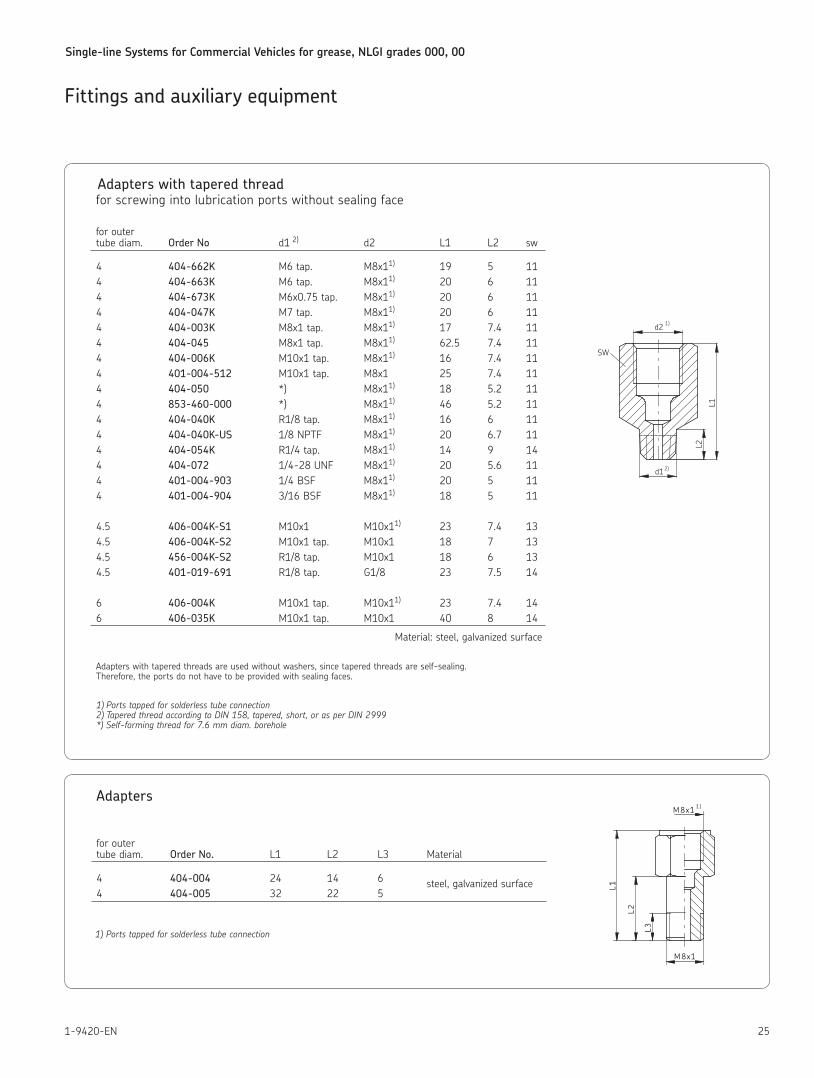
Adapters with tapered thread for screwing into lubrication ports without sealing face
for outer tube diam Order No d1 2) d2 L1 L2 sw
4 404-662K M6 tap M8x11) 19 5 11 4 404-663K M6 tap M8x11) 20 6 11 4 404-673K M6x0 75 tap M8x11) 20 6 11 4 404-047K M7 tap M8x11) 20 6 11 4 404-003K M8x1 tap M8x11) 17 7 4 11 4 404-045 M8x1 tap M8x11) 62 5 7 4 11 4 404-006K M10x1 tap M8x11) 16 7 4 11 4 401-004-512 M10x1 tap M8x1 25 7 4 11 4 404-050 *) M8x11) 18 5 2 11 4 853-460-000 *) M8x11) 46 5 2 11 4 404-040K R1/8 tap M8x11) 16 6 11 4 404-040K-US 1/8 NPTF M8x11) 20 6 7 11 4 404-054K R1/4 tap M8x11) 14 9 14 4 404-072 1/4-28 UNF M8x11) 20 5 6 11 4 401-004-903 1/4 BSF M8x11) 20 5 11 4 401-004-904 3/16 BSF M8x11) 18 5 11
4 5 406-004K-S1 M10x1 M10x11) 23 7 4 13 4 5 406-004K-S2 M10x1 tap M10x1 18 7 13 4 5 456-004K-S2 R1/8 tap M10x1 18 6 13 4 5 401-019-691 R1/8 tap G1/8 23 7 5 14
6 406-004K M10x1 tap M10x11) 23 7 4 14 6 406-035K M10x1 tap M10x1 40 8 14
Material: steel, galvanized surface
Adapters with tapered threads are used without washers, since tapered threads are self-sealing Therefore, the ports do not have to be provided with sealing faces
1) Ports tapped for solderless tube connection2) Tapered thread according to DIN 158, tapered, short, or as per DIN 2999*) Self-forming thread for 7.6 mm diam. borehole
d2
d1
L2
L1
SW
1)
2)
Adapters
for outer tube diam Order No. L1 L2 L3 Material
4 404-004 24 14 6 steel, galvanized surface 4 404-005 32 22 5
1) Ports tapped for solderless tube connection L3
L2
L1
M 8x1
M8x1 1)
Single-line Systems for Commercial Vehicles for grease, NLGI grades 000, 00
26 1-9420-EN
Fittings and auxiliary equipment
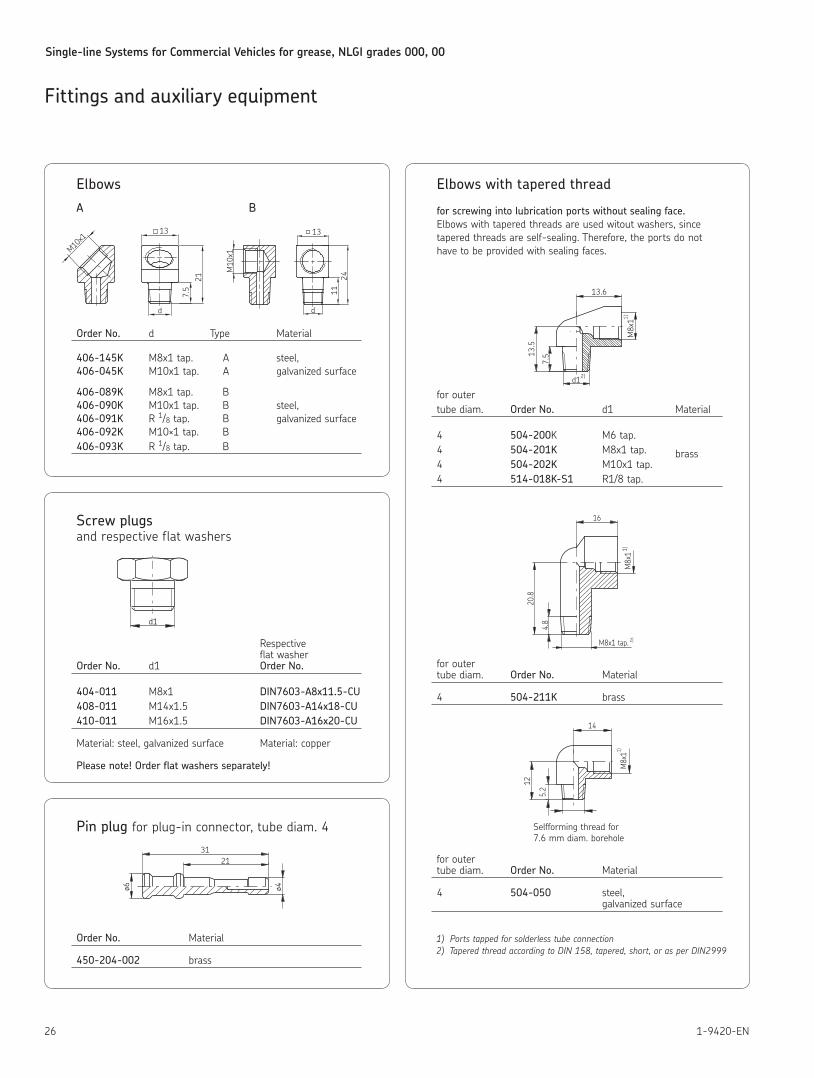
Elbows
A B
Order No. d Type Material
406-145K M8x1 tap A steel, 406-045K M10x1 tap A galvanized surface
406-089K M8x1 tap B 406-090K M10x1 tap B steel, 406-091K R 1/8 tap B galvanized surface 406-092K M10×1 tap B 406-093K R 1/8 tap B
M10x1
13
d
7.5
21
Pin plug for plug-in connector, tube diam 4
Order No. Material
450-204-002 brass
Screw plugs and respective flat washers
Respective flat washer Order No. d1 Order No.
404-011 M8x1 DIN7603-A8x11.5-CU 408-011 M14x1 5 DIN7603-A14x18-CU 410-011 M16x1 5 DIN7603-A16x20-CU
Material: steel, galvanized surface Material: copper
Please note! Order flat washers separately!
13M10x1
d
1124
d1
ø4ø6
2131
Elbows with tapered thread
for screwing into lubrication ports without sealing face.Elbows with tapered threads are used witout washers, since tapered threads are self-sealing Therefore, the ports do not have to be provided with sealing faces
for outer tube diam Order No. d1 Material
4 504-200K M6 tap 4 504-201K M8x1 tap brass 4 504-202K M10x1 tap 4 514-018K-S1 R1/8 tap
for outer tube diam Order No. Material
4 504-211K brass
for outer tube diam Order No. Material
4 504-050 steel, galvanized surface
1) Ports tapped for solderless tube connection2) Tapered thread according to DIN 158, tapered, short, or as per DIN2999
13.6
7.513
.5
d1
M8x11)
2)
16
4.8
20.8
M8x
11)
2)M8x1 tap.
14
5.2
12
1)M8x1
Selfforming thread for7 6 mm diam borehole
Single-line Systems for Commercial Vehicles for grease, NLGI grades 000, 00
271-9420-EN
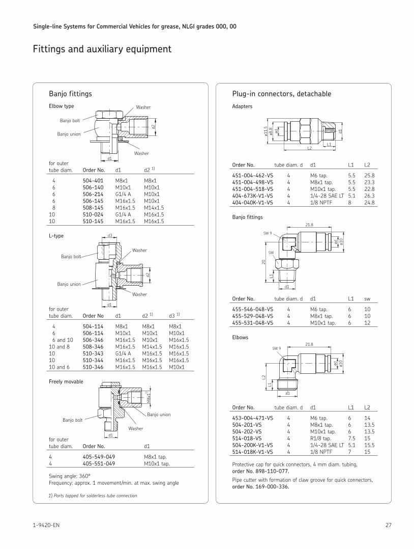
Banjo fittings
Elbow type
for outer tube diam Order No. d1 d2 1)
4 504-401 M8x1 M8x1 6 506-140 M10x1 M10x1 6 506-214 G1/4 A M10x1 6 506-145 M16x1 5 M10x1 8 508-145 M16x1 5 M14x1 5 10 510-024 G1/4 A M16x1 5 10 510-145 M16x1 5 M16x1 5
L-type
for outer tube diam Order No d1 d2 1) d3 1)
4 504-114 M8x1 M8x1 M8x1 6 506-114 M10x1 M10x1 M10x1 6 and 10 506-346 M16x1 5 M10x1 M16x1 5 10 and 8 508-346 M16x1 5 M14x1 5 M16x1 5 10 510-343 G1/4 A M16x1 5 M16x1 5 10 510-344 M16x1 5 M16x1 5 M16x1 5 10 and 6 510-346 M16x1 5 M16x1 5 M10x1
Freely movable
for outer tube diam Order No. d1
4 405-549-049 M8x1 tap 4 405-551-049 M10x1 tap
Swing angle: 360°Frequency: approx 1 movement/min at max swing angle
1) Ports tapped for solderless tube connection
Fittings and auxiliary equipment
d1d2
Banjo bolt
Banjo union
Washer
Washer
d1
d2
d3
Banjo bolt
Banjo union
Washer
Washer
d1
M8x11)
Banjo union
Washer
Banjo bolt
Plug-in connectors, detachable
Adapters
Order No. tube diam d d1 L1 L2
451-004-462-VS 4 M6 tap 5 5 25 8 451-004-498-VS 4 M8x1 tap 5 5 23 3 451-004-518-VS 4 M10x1 tap 5 5 22 8 404-673K-V1-VS 4 1/4-28 SAE LT 5 1 26 3 404-040K-V1-VS 4 1/8 NPTF 8 24 8
Banjo fittings
Order No. tube diam d d1 L1 sw
455-546-048-VS 4 M6 tap 6 10 455-529-048-VS 4 M8x1 tap 6 10 455-531-048-VS 4 M10x1 tap 6 12
Elbows
Order No. tube diam d d1 L1 L2
453-004-471-VS 4 M6 tap 6 14 504-201-VS 4 M8x1 tap 6 13 5 504-202-VS 4 M10x1 tap 6 13 5 514-018-VS 4 R1/8 tap 7 5 15 504-200K-V1-VS 4 1/4-28 SAE LT 5 1 15 5 514-018K-V1-VS 4 1/8 NPTF 7 15
Protective cap for quick connectors, 4 mm diam tubing, order No. 898-110-077.
Pipe cutter with formation of claw groove for quick connectors, order No. 169-000-336.
d1ødø8.8
ø11.5
L1L2
SW
SW 9
d1
L1
20
21.8
ød ø10
L2L1
SW 9
ø10
ød
d1
21.8
Single-line Systems for Commercial Vehicles for grease, NLGI grades 000, 00
28 1-9420-EN
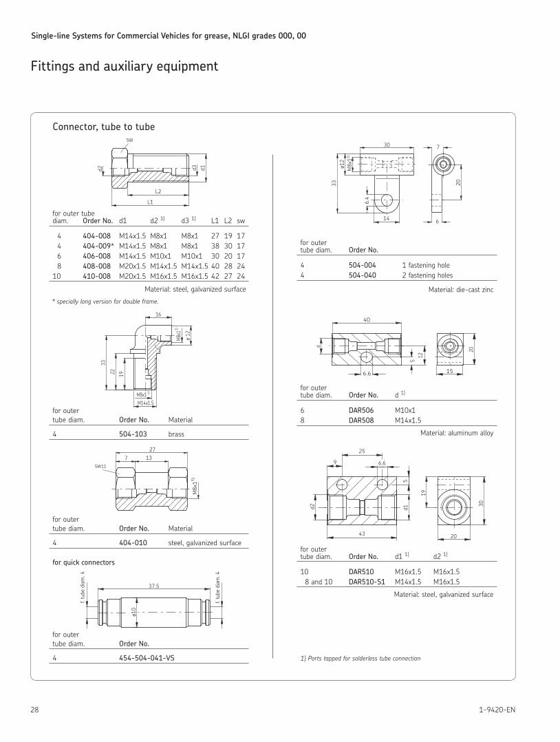
Connector, tube to tube
for outer tube diam Order No. d1 d2 1) d3 1) L1 L2 sw
4 404-008 M14x1 5 M8x1 M8x1 27 19 17 4 404-009* M14x1 5 M8x1 M8x1 38 30 17 6 406-008 M14x1 5 M10x1 M10x1 30 20 17 8 408-008 M20x1 5 M14x1 5 M14x1 5 40 28 24 10 410-008 M20x1 5 M16x1 5 M16x1 5 42 27 24
Material: steel, galvanized surface
* specially long version for double frame.
for outer tube diam Order No. Material
4 504-103 brass
for outer tube diam Order No. Material
4 404-010 steel, galvanized surface
for quick connectors
for outer tube diam Order No.
4 454-504-041-VS
for outer tube diam Order No.
4 504-004 1 fastening hole 4 504-040 2 fastening holes
Material: die-cast zinc
for outer tube diam Order No. d 1)
6 DAR506 M10x1 8 DAR508 M14x1 5
Material: aluminum alloy
for outer tube diam Order No. d1 1) d2 1)
10 DAR510 M16x1 5 M16x1 5 8 and 10 DAR510-S1 M14x1 5 M16x1 5
Material: steel, galvanized surface
1) Ports tapped for solderless tube connection
Fittings and auxiliary equipment
L2
L1
d3 d1d2
SW
16
1922
33
ø 12
M8x11)
M8x1
1)
M14x1.5
13727
M8x11)
SW11
f. tu
be d
iam
. 4
ø10
f. tu
be d
iam
. 4
37.5
7
20
6
30
M8x1
ø12
33
6.4
1)
14
d40
512
6.6 15
20
30
20
5
43
d2
25
9 6.6
d1
19
Single-line Systems for Commercial Vehicles for grease, NLGI grades 000, 00
291-9420-EN
Fittings and auxiliary equipment
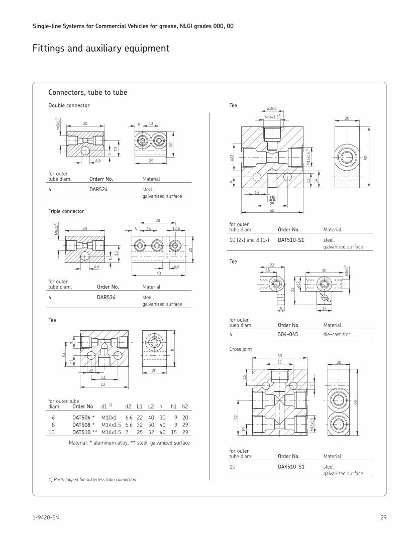
Connectors, tube to tube
Double connector
for outer tube diam Orderr No. Material
4 DAR524 steel, galvanized surface
Triple connector
for outer tube diam Order No. Material
4 DAR534 steel, galvanized surface
Tee
for outer tube diam Order No d1 1) d2 L1 L2 h h1 h2
6 DAT506 * M10x1 6 6 22 40 30 9 20 8 DAT508 * M14x1 5 6 6 32 50 40 9 29 10 DAT510 ** M16x1 5 7 25 52 40 15 29
Material: * aluminum alloy; ** steel, galvanized surface
1) Ports tapped for solderless tube connection
Tee
for outer tube diam Order No. Material
10 (2x) and 8 (1x) DAT510-S1 steel, galvanized surface
Tee
for outer tueb diam Order No Material
4 504-045 die-cast zinc
Cross joint
for outer tube diam Order No. Material
10 DAK510-S1 steel, galvanized surface
30
513
M8x11)
6.6
6 13
25
20
30
513
M8x11)
6.6
6 14
20
40
13.5
6.6
28
( )
20
L2
h1
d2
L1
h
d1
h2
6.6M8
25
50
M14x1.5
ø18.5
12 14
M16x1.5
ø22
9
20
50
1)
1)
1522
30
ø12
24
6 14
1)
6.4
M8x1
1510
32
7M16
x1.5
25
60
20
50
Single-line Systems for Commercial Vehicles for grease, NLGI grades 000, 00
30 1-9420-EN
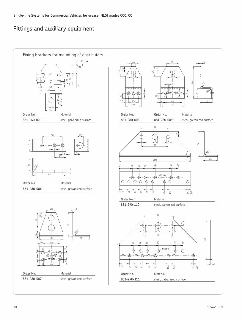
Fixing brackets for mounting of distributors
Order No. Material
881-260-020 steel, galvanized surface
Order No. Material
881-280-006 steel, galvanized surface
Order No. Material
881-280-007 steel, galvanized surface
Order No. Order No. Material
881-280-008 881-280-009 steel, galvanized surface
Order No. Material
881-290-110 steel, galvanized surface
Order No. Material
881-290-111 steel, galvanized surface
Fittings and auxiliary equipmentR3.535
30
50
7
29
83
14
15
3
9
35
3
15
8 5066
30
77
11
1030 35
63
1515
R470
28
10
R3.5
45
16.5
70 50
3
77
4811
11
50
30
20
11
ø7
10
2010
3
25
80 R4R4
6 4860
2
31
14
25
11.5
7
7
1512
32
10
11.5
14
40
25
7.5
12
7
25
159 9
40
70
200
191
126
141
43 59 76 93260 9
ø7(15x)
80
10
200
164
145
100
7255350
R3.5
15
75
159 9
105
200
191
126
141
43 59 76 93260 9
ø7(15x)
80
164
145
100
7255350
3
15
75
Single-line Systems for Commercial Vehicles for grease, NLGI grades 000, 00
311-9420-EN
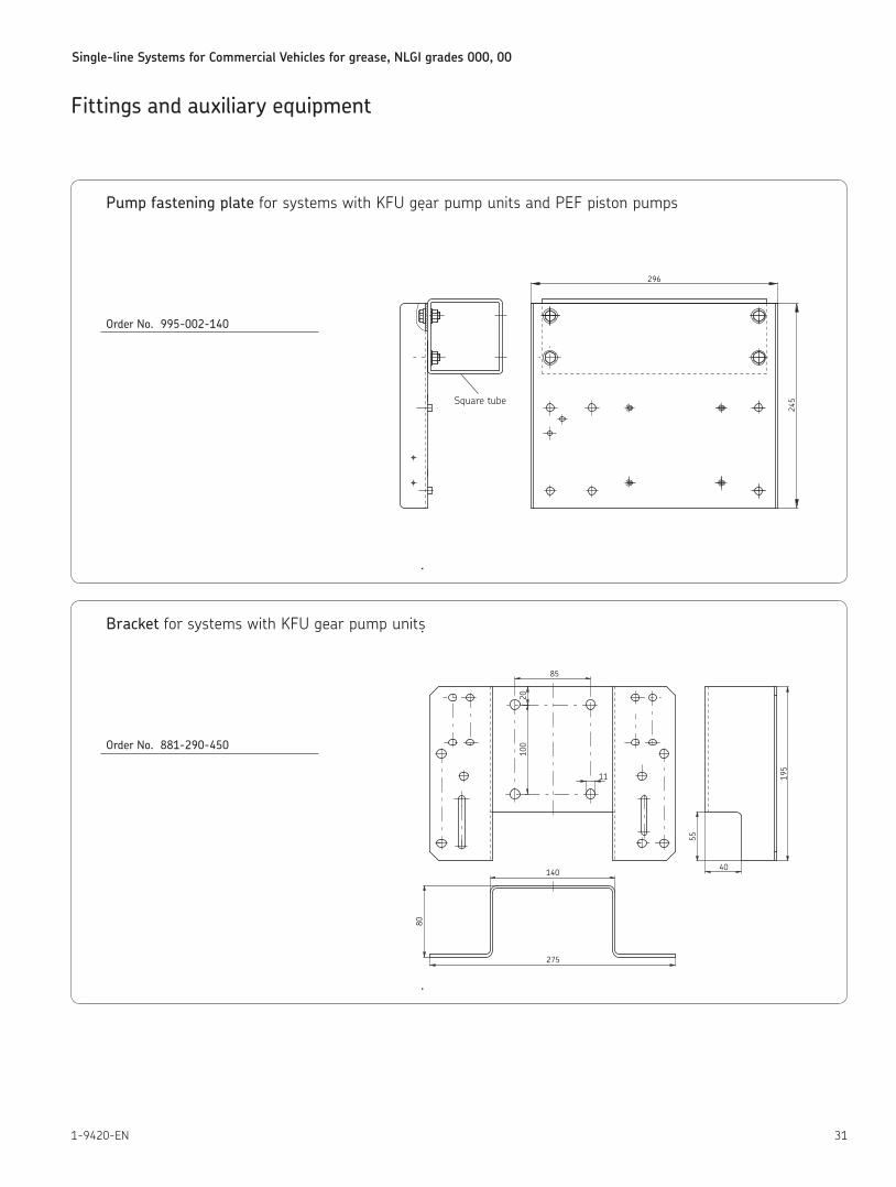
Pump fastening plate for systems with KFU gear pump units and PEF piston pumps
Order No. 995-002-140
Fittings and auxiliary equipment
296
245
Bracket for systems with KFU gear pump units
Order No. 881-290-450
275
80
140
20100
11
85
195
55
40
Square tube
Single-line Systems for Commercial Vehicles for grease, NLGI grades 000, 00
32 1-9420-EN
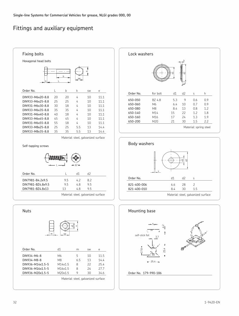
Fixing bolts
Hexagonal head bolts
Order No. L b k sw e
DIN933-M6x20-8.8 20 20 4 10 11 1 DIN933-M6x25-8.8 25 25 4 10 11 1 DIN931-M6x30-8.8 30 18 4 10 11 1 DIN933-M6x35-8.8 35 35 4 10 11 1 DIN931-M6x40-8.8 40 18 4 10 11 1 DIN933-M6x45-8.8 45 45 4 10 11 1 DIN931-M6x55-8.8 55 18 4 10 11 1 DIN933-M8x25-8.8 25 25 5 5 13 14 4 DIN933-M8x35-8.8 35 35 5 5 13 14 4
Material: steel, galvanized surface
Self-tapping screws
Order No. L d1 d2
DIN7981-B4.2x9.5 9 5 4 2 8 2 DIN7981-BZ4.8x9.5 9 5 4 8 9 5 DIN7981-BZ4.8x13 13 4 8 9 5
Material: steel, galvanized surface
Fittings and auxiliary equipment
b
Lksw
e
L
d1
d2
Nuts
Order No. d1 m sw e
DIN934-M6-8 M6 5 10 11 5 DIN934-M8-8 M8 6 5 13 14 4 DIN936-M14x1.5-5 M14x1 5 8 22 25 4 DIN936-M16x1.5-5 M16x1 5 8 24 27 7 DIN936-M20x1.5-5 M20x1 5 9 30 34 6
Material: steel, galvanized surface
m
e
sw
d1
Lock washers
Order No. for bolt d1 d2 s h
650-050 BZ 4 8 5 3 9 0 6 0 9 650-060 M6 6 4 10 0 7 0 9 650-080 M8 8 4 13 0 8 1 2 650-140 M14 15 22 1 2 1 8 650-160 M16 17 24 1 3 1 9 650-200 M20 21 30 1 5 2 2
Material: spring steel
Body washers
Order No. d1 d2 s
821-400-006 6 6 28 2 821-400-010 8 4 30 1 5
Material: steel, galvanized surface
Mounting base
Order No. 179-990-186
s
d1 d2
h
s
d2d1
5
4.2
3.7
17.8
25.4
25.4
self-stick foil
Single-line Systems for Commercial Vehicles for grease, NLGI grades 000, 00
331-9420-EN
Fittings and auxiliary equipment
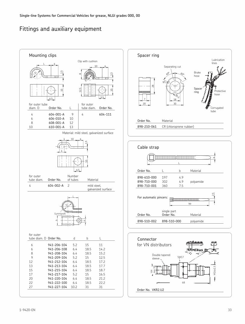
Mounting clips
Clip with cushion
for outer tube for outer diam D Order No. L tube diam Order No.
4 604-001-A 9 4 604-111 6 606-010-A 10 8 608-001-A 12 10 610-001-A 13
Material: mild steel, galvanized surface
for outer Number tube diam Order No. of tubes Material
4 604-002-A 2 mild steel, galvanized surface
for outer tube diam D Order No. d b L
6 941-206-104 5 2 15 11 6 941-206-108 6 4 18 5 14 2 8 941-208-104 6 4 18 5 15 2 9 941-209-104 5 2 15 12 5 12 941-212-104 6 4 18 5 17 2 13 941-213-104 6 4 18 5 17 7 15 941-215-104 6 4 18 5 18 7 17 941-217-104 5 2 15 16 5 20 941-220-104 6 4 18 5 21 2 22 941-222-100 6 4 18 5 22 2 27 941-227-104 10 2 31 31
1.5
L 6
D
10
6.5
1.5
10 6
4
10
5.5
812.5
6.5
104
1.5
4
10
6
L
db
D
Gummiprofil
Spacer ring
Order No. Material
898-210-061 CR (chloroprene rubber)
3020
18
R6.5
R3
60° 60°
7
28
Separating cut
Lubrication lines
Brake hose
Spacer ring
Corrugatedtube
Protective hose
Cable strap
Order No. L b Material
898-610-000 197 4 9 898-710-000 302 4 9 polyamide 898-710-001 360 7 5
For automatic pincers:
single part Order No. Order No. Material
898-510-002 898-510-000 polyamide
Connector for VN distributors
Order No. VKR2.U2
b
L
99
2.5
SW17
68
tube
diam.
10
M16
x1.5
Double taperedsleeve
Single-line Systems for Commercial Vehicles for grease, NLGI grades 000, 00
34 1-9420-EN
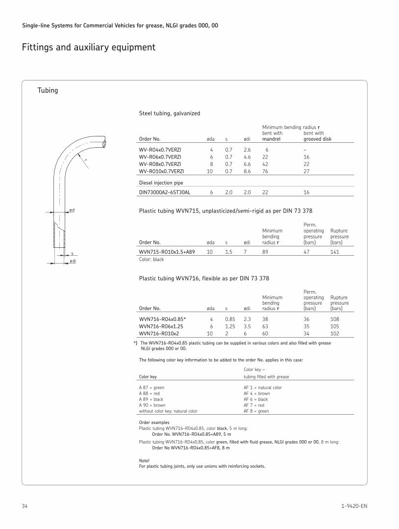
Tubing
Steel tubing, galvanized
Minimum bending radius r bent with bent with Order No. øda s ødi mandrel grooved disk
WV-RO4x0.7VERZI 4 0 7 2 6 6 – WV-RO6x0.7VERZI 6 0 7 4 6 22 16 WV-RO8x0.7VERZI 8 0 7 6 6 42 22 WV-RO10x0.7VERZI 10 0 7 8 6 76 27
Diesel injection pipe
DIN73000A2-6ST30AL 6 2 0 2 0 22 16
Plastic tubing WVN715, unplasticized/semi-rigid as per DIN 73 378
Perm Minimum operating Rupture bending pressure pressure Order No. øda s ødi radius r (bars) (bars)
WVN715-RO10x1.5+A89 10 1 5 7 89 47 141Color: black
Plastic tubing WVN716, flexible as per DIN 73 378
Perm Minimum operating Rupture bending pressure pressure Order No. øda s ødi radius r (bars) (bars)
WVN716-RO4x0.85* 4 0 85 2 3 38 36 108WVN716-RO6x1.25 6 1 25 3 5 63 35 105 WVN716-RO10x2 10 2 6 60 34 102
*) The WVN716-RO4x0.85 plastic tubing can be supplied in various colors and also filled with grease NLGI grades 000 or 00.
The following color key information to be added to the order No. applies in this case:
Color key –
Color key tubing filled with grease
A 87 = green AF 1 = natural color A 88 = red AF 4 = brown A 89 = black AF 6 = black A 90 = brown AF 7 = red without color key: natural color AF 8 = green
Order examplesPlastic tubing WVN716-RO4x0 85, color black, 5 m long:
Order No. WVN716-RO4x0.85+A89, 5 m
Plastic tubing WVN716-RO4x0 85, color green, filled with fluid grease, NLGI grades 000 or 00, 8 m long: Order No WVN716-RO4x0.85+AF8, 8 m
Note!For plastic tubing joints, only use unions with reinforcing sockets.
Fittings and auxiliary equipment
s
ød
r
ødi
Single-line Systems for Commercial Vehicles for grease, NLGI grades 000, 00
351-9420-EN
Fittings and auxiliary equipment
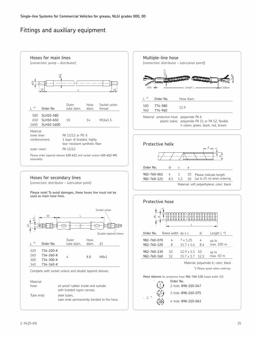
Hoses for main lines(connection: pump – distributor)
Outer Hose Socket union L +5 Order No tube diam diam thread
580 SLH10-580 650 SLH10-650 10 14 M16x1 5 1600 SLH10-1600
Material inner liner: PA 11/12 or PE-E reinforcement: 1 layer of braided, highly tear-resistant synthetic fiber
outer cover: PA 11/12
Please order tapered sleeves 410-611 and socket unions 410-612-MS separately
ø10
L30 30
ø14
Hoses for secondary lines(connection: distributor – lubrication point)
Please note! To avoid damages, these hoses line must not be used as main hose lines.
Outer Hose L +5 Order No. tube diam diam d3
220 734-220-K 260 734-260-K 4 8 8 M8x1 300 734-300-K 340 734-340-K
Complete with socket unions and double tapered sleeves
Material hose: oil-proof rubber inside and outside with braided rayon carcass
Tube ends: steel tubes, tube ends permanently bonded to the hose
L30
d3
ø 4
Socket union
Double tapered sleeve
Multiple-line hose(connection: distributor – lubrication point))
L +5 Order No. Hose diam
580 774-580 12 9 960 774-960
Material protective hose: polyamide PA 6 plastic tubes: polyamide PA 11 or PA 12, flexible 4 colors: green, black, red, brown
ø12.
9
600 Length L 300
ø4
Protective helix
Order No. di s a
982-760-061 4 1 10 Please indicate length 982-760-121 8 5 1 5 10 (up to 25 m) when ordering
Material: soft polyethylene; color: black
di
sa
Protective hose
Order No. Rated width da x s di Length L *)
982-760-070 4 7 x 1 25 4 up to 982-760-120 8 11 7 x 1 6 8 4 max 100 m
982-760-130 10 12 9 x 1 5 10 up to 982-760-160 12 15 7 x 1 7 12 3 max 50 m
Material: polyamide 6; color: black
*) Please quote when ordering.
Hose sleeves for protective hose 982-760-130 (rated width 10)
Order No.2-hole: 898-210-047
3-hole: 898-210-075
4-hole: 898-210-063
dida
s
L
24
Single-line Systems for Commercial Vehicles for grease, NLGI grades 000, 00
36 1-9420-EN
Fittings and auxiliary equipment
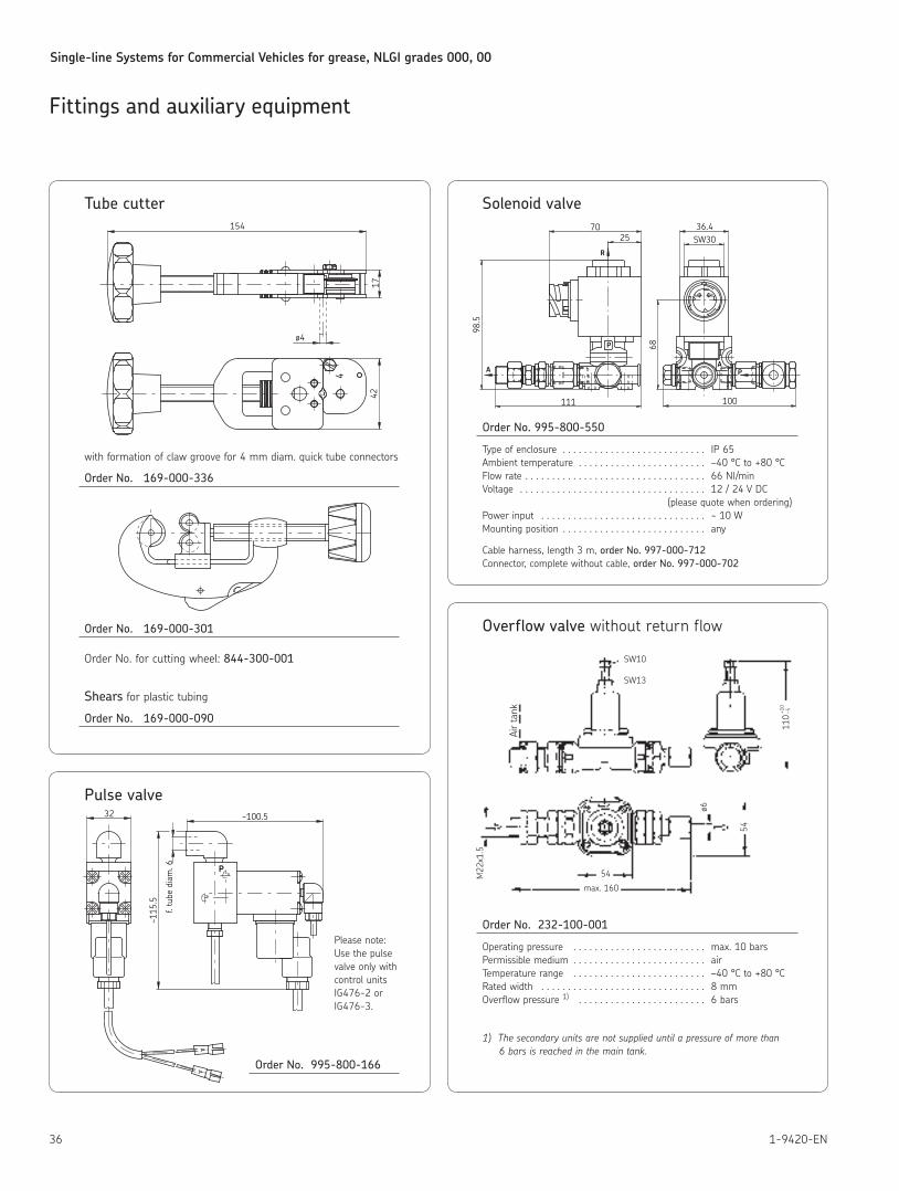
Tube cutter
with formation of claw groove for 4 mm diam quick tube connectors
Order No. 169-000-336
Order No. 169-000-301
Order No for cutting wheel: 844-300-001
Shears for plastic tubing
Order No. 169-000-090
154
4217
ø44
Pulse valve
Please note: Use the pulse valve only with control units IG476-2 or IG476-3
Order No. 995-800-166
32 ~100.5
~115
.5
f. tu
be d
iam
. 6 P
Solenoid valve
Order No. 995-800-550
Type of enclosure IP 65 Ambient temperature –40 °C to +80 °C Flow rate 66 Nl/min Voltage 12 / 24 V DC
(please quote when ordering)Power input ~ 10 W Mounting position any
Cable harness, length 3 m, order No. 997-000-712Connector, complete without cable, order No. 997-000-702
P
R
4 1
AA P
100111
98.5
SW3036.4
2570
68
Overflow valve without return flow
Order No. 232-100-001
Operating pressure max 10 bars Permissible medium air Temperature range –40 °C to +80 °C Rated width 8 mm Overflow pressure 1) 6 bars
1) The secondary units are not supplied until a pressure of more than 6 bars is reached in the main tank.
54
max. 160
M22
x1.5
ø6
54
110
+10
–5
SW10
SW13
Air
tank
Single-line Systems for Commercial Vehicles for grease, NLGI grades 000, 00
371-9420-EN
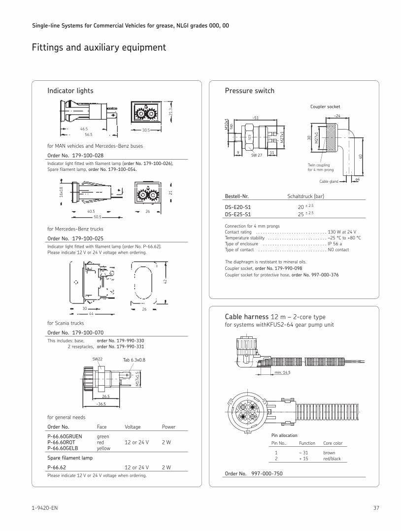
Indicator lights
for MAN vehicles and Mercedes-Benz buses
Order No. 179-100-028Indicator light fitted with filament lamp (order No. 179-100-026),Spare filament lamp, order No. 179-100-054.
for Mercedes-Benz trucks
Order No. 179-100-025Indicator light fitted with filament lamp (order No P-66 62) Please indicate 12 V or 24 V voltage when ordering
for Scania trucks
Order No. 179-100-070This includes: base, order No. 179-990-330 2 reseptacles, order No. 179-990-331
for general needs
Order No. Face Voltage Power
P-66.60GRUEN green P-66.60ROT red 12 or 24 V 2 W P-66.60GELB yellow
Spare filament lamp
P-66.62 12 or 24 V 2 WPlease indicate 12 V or 24 V voltage when ordering
Fittings and auxiliary equipment
46.556.5
30.5
21.3
40.550.5
26
16x18
21
3044
26
42
SW22 Tab 6.3x0.8
M17
x1.5
26.5
~36.5
Pressure switch
Coupler socket
Bestell-Nr. Schaltdruck (bar)
DS-E20-S1 20 ± 2 5 DS-E25-S1 25 ± 2 5
Connection for 4 mm prongs Contact rating 130 W at 24 V Temperature stability –25 °C to +80 °C Type of enclosure IP 56 a Type of contact NO contact
The diaphragm is restistant to mineral oils Coupler socket, order No. 179-990-098 Coupler socket for protective hose, order No. 997-000-376
SW 27E25
M10
x1
M27
x1
~51
9 11
tap.
M27
x1
30
~24
40
ø4
Twin couplingfor 4 mm prong
Cable gland
Cable harness 12 m – 2-core type for systems withKFUS2-64 gear pump unit
Pin allocation
Pin No Function Core color
1 – 31 brown 2 + 15 red/black
Order No. 997-000-750
2
3
4
1
min. 14.5
Single-line Systems for Commercial Vehicles for grease, NLGI grades 000, 00
38 1-9420-EN
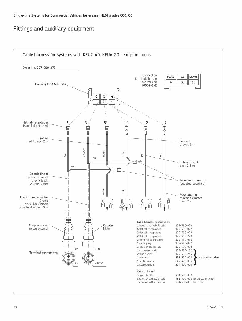
Fittings and auxiliary equipment
Cable harness for systems with KFU2-40, KFU6-20 gear pump units
Order No. 997-000-373
Cable harness, consisting of: 1 housing for A M P tabs 179-990-076 6 flat tab receptacles 179-990-077 2 flat tab receptacles 179-990-079 2 flat tab receptacles 179-990-279 2 terminal connections 179-990-090 1 cable plug 179-990-082 1 coupler socket (DS) 179-990-098 1 connector shell 179-990-272 2 plug sockets 179-990-264 1 plug cap 898-320-023 Motor connection 1 socket union 847-420-006 1 socket union 824-400-004
Cable 1 5 mm2 single-sheathed 981-900-008 double-sheathed, 2-core 981-900-018 for pressure switch double-sheathed, 2-core 981-900-031 for motor
PS/CS
SL
15
31
DK/MK
BK + BK/VT
GY - BN
- BN
RD/B
K
M
- BN
+ BK
/VT
BK
GY
6 3-
BN
RD/B
K
PK BU
5 1
23 1
56 4
2 4
}
Connection terminals for the
control unit IG502-2-EHousing for A.M.P. tabs
Ground brown, 2 m
Indicator light pink, 2 5 m
Terminal connector (supplied detached)
Pushbuton or machine contact blue, 2 m
Flat tab receptacles (supplied detached)
Ignition red / black, 2 m
Electric line to pressure switch
grey + black, 2-core, 9 mm
Electric line to motor, 2-core
black-lilac / brown double sheathed, 9 m
Coupler socket pressure switch
Terminal connections
CouplerMotor
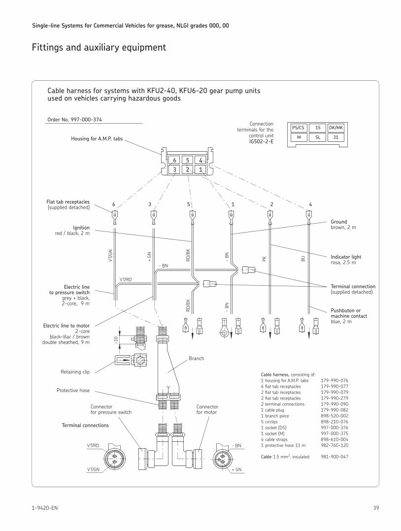
Single-line Systems for Commercial Vehicles for grease, NLGI grades 000, 00
391-9420-EN
Fittings and auxiliary equipment
Cable harness for systems with KFU2-40, KFU6-20 gear pump units used on vehicles carrying hazardous goods
Order No. 997-000-374
Cable harness, consisting of: 1 housing for A M P tabs 179-990-076 6 flat tab receptacles 179-990-077 2 flat tab receptacles 179-990-079 2 flat tab receptacles 179-990-279 2 terminal connections 179-990-090 1 cable plug 179-990-082 1 branch piece 898-520-002 5 circlips 898-210-076 1 socket (DS) 997-000-376 1 socket (M) 997-000-375 4 cable straps 898-610-004 1 protective hose 11 m 982-760-120
Cable 1 5 mm2, insulated 981-900-047
PS/CS
SL
15
31
DK/MK
M
23 1
56 4
6 3 5 1 2 4
VT/RD
- BN
RD/B
K
- BN
RD/B
K
- BN
PK BU
+ GN
- BNVT/RD
VT/GN
+ GN
VT/G
N~1
0
Housing for A.M.P. tabs
Connectionterminals for the
control unitIG502-2-E
Flat tab receptacles (supplied detached)
Ignition red / black, 2 m
Electric line to pressure switch
grey + black, 2-core, 9 m
Electric line to motor 2-core
black-lilac / brown double sheathed, 9 m
Retaining clip
Protective hose
Ground brown, 2 m
Indicator light rosa, 2 5 m
Terminal connection (supplied detached)
Pushbuton or machine contact blue, 2 m
Terminal connections
Branch
Connectorfor pressure switch
Connectorfor motor
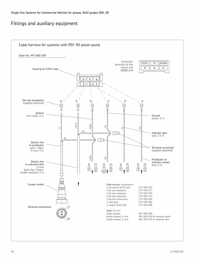
Single-line Systems for Commercial Vehicles for grease, NLGI grades 000, 00
40 1-9420-EN
Fittings and auxiliary equipment
Cable harness for systems with PEF-90 piston pump
Order No. 997-000-189
Cable harness, consisting of: 1 housing for A M P tabs 179-990-076 4 flat tab receptacles 179-990-077 2 flat tab receptacles 179-990-079 3 flat tab receptacles 179-990-279 2 terminal connections 179-990-090 1 cable plug 179-990-082 1 coupler socket (DS) 179-990-098
Cable 1 5 mm2 single-sheated 981-900-008 double sheated, 2-core 981-900-018 for pressure switch double sheated, 2-core 981-900-031 for solenoid valve
6 3 5 1
23
2 4
- BN
+ BK
/VT
BK
GY
- BN
RD/B
K
- BN
RD/B
K
PK BU
BK
GY
PS/CS
SL
15
31
DK/MK
M
1
56 4
Connectionterminals for the
control unit IG502-2-EHousing for A.M.P. tabs
Ground brown, 2 m
Indicator light pink, 2 5 m
Terminal connection (supplied detached)
Pushbuton or machine contact blue, 2 m
Flat tab receptacles (supplied detached)
Ignition red / black, 2 m
Electric line to pushbuton grey + black, 2-core, 9 m
Electric line to solenoid valve
2-core black-lilac / brown
double sheathed, 9 m
Coupler socket
Terminal connections
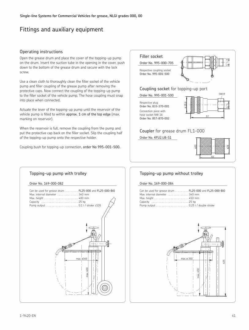
Single-line Systems for Commercial Vehicles for grease, NLGI grades 000, 00
411-9420-EN
Fittings and auxiliary equipment
Filler socketOrder No. 995-000-705
Respective coupling socket Order No. 995-001-500
Coupling socket for topping-up portOrder No. 995-001-500
Respective plug Order No. 833-370-001
Connection piece with hose socket NW 16 Order No. 857-870-002
Coupler for grease drum FL1-000Order No. KFU2.U8-S1
Operating instructionsOpen the grease drum and place the cover of the topping-up pump on the drum Insert the suction tube in the opening in the cover, push down to the bottom of the grease drum and secure with the lock screw
Use a clean cloth to thoroughly clean the filler socket of the vehicle pump and filler coupling of the grease pump after removing the protective caps Now connect the coupling of the topping-up pump to the filler socket of the vehicle pump The hose coupling must snap into place when connected
Actuate the lever of the topping-up pump until the reservoir of the vehicle pump is filled to within approx. 1 cm of the top edge (max marking on reservoir)
When the reservoir is full, remove the coupling from the pump and put the protective cap back on the filler socket Slip the coupling half of the topping-up pump onto the respective holder
Coupling bush for topping-up connection, order No 995-001-500.
Topping-up pump with trolley
Order No. 169-000-082
Can be used for grease drum FL25-000 and FL25-000-BIO Max internal diameter 340 mm Max height 400 mm Capacity 25 kg Pump output 0 1 l / stroke ±10%
max. ø340
max
. 400
G 1 /
4 A
ø 28
.6
G 1 /
4
57
SW19
Topping-up pump without trolley
Order No. 169-000-084
Can be used for grease drum FL25-000 and FL25-000-BIO Max internal diameter 340 mm Max height 450 mm Capacity 25 kg Pump output 0 25 l / double stroke
ø30
ø28
44
max. ø 350
max
. 450
635
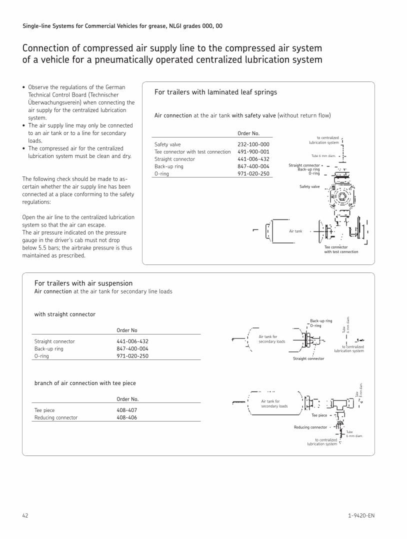
Single-line Systems for Commercial Vehicles for grease, NLGI grades 000, 00
42 1-9420-EN
Connection of compressed air supply line to the compressed air system of a vehicle for a pneumatically operated centralized lubrication system
• Observe the regulations of the German Technical Control Board (Technischer Überwachungs verein) when connecting the air supply for the centralized lubrication system
• The air supply line may only be connected to an air tank or to a line for secondary loads
• The compressed air for the centralized lubrication system must be clean and dry
The following check should be made to as-certain whether the air supply line has been connected at a place conforming to the safety regulations:
Open the air line to the centralized lubrication system so that the air can escape The air pressure indicated on the pressure gauge in the driver‘s cab must not drop below 5 5 bars; the airbrake pressure is thus maintained as prescribed
For trailers with air suspensionAir connection at the air tank for secondary line loads
with straight connector
Order No
Straight connector 441-006-432 Back-up ring 847-400-004 O-ring 971-020-250
branch of air connection with tee piece
Order No.
Tee piece 408-407 Reducing connector 408-406
Air tank forsecondary loads
Back-up ringO-ring
Straight connector
to centralizedlubrication system
Tube
6
mm
dia
m.
Air tank forsecondary loads
Tee piece
Reducing connector
to centralizedlubrication system
Tube 6 mm diam.
Tube
8 m
m d
iam.
For trailers with laminated leaf springs
Air connection at the air tank with safety valve (without return flow)
Order No.
Safety valve 232-100-000 Tee connector with test connection 491-900-001 Straight connector 441-006-432 Back-up ring 847-400-004 O-ring 971-020-250
to centralizedlubrication system
Tube 6 mm diam.
Straight connectorBack-up ring
O-ring
Safety valve
Air tank
Tee connectorwith test connection

skf.com/lubrication
SKF Lubrication Systems Germany GmbHHockenheim Plant 2. Industriestrasse 4 68766 Hockenheim Germany
Tel. +49 (0)6205 27-0 Fax +49 (0)6205 27-100
This brochure was presented by:
® SKF is a registered trademark of the SKF Group.
© SKF Group 2014The contents of this publication are the copyright of the publisher and may not be reproduced (even extracts) unless prior written per-mission is granted. Every care has been taken to ensure the accuracy of the information contained in this publication but no liability can be accepted for any loss or damage whether direct, indirect or consequential arising out of the use of the information contained herein.
1-9420-EN · September 2014
Bearings and unitsSeals Lubrication
systems
Mechatronics Services
The Power of Knowledge Engineering
Drawing on five areas of competence and application-specific expertise amassed over more than 100 years, SKF brings innovative solutions to OEMs and production facilities in every major industry world-wide. These five competence areas include bearings and units, seals, lubrication systems, mechatronics (combining mechanics and electronics into intelligent systems), and a wide range of services, from 3-D computer modelling to advanced condition monitoring and reliability and asset management systems. A global presence provides SKF customers uniform quality standards and worldwide product availability.
! Important information on product usageAll products from SKF may be used only for their intended purpose as described in this
brochure and the operating instructions. If operating instructions are supplied together with the products, they must be read and followed.
Not all lubricants can be fed using centralized lubrication systems. SKF can, on request, inspect the feedability of the lubricant selected by the user in centralized lubrication systems. Lubrication systems and their components manufactured by SKF are not approved for use in conjunction with gases, liquefied gases, pressurized gases in solution, vapors or such fluids whose vapor pressure exceeds normal atmospheric pressure (1 013 mbar) by more than 0,5 bar at their maximum permissible temperature.
In particular, we call your attention to the fact that hazardous materials of any kind, especially the materials classified as hazardous by EC Directive 67/548/EEC, Article 2, Para. 2, may only be filled into SKF centralized lubrication systems and components and delivered and/or distributed with the same after consultation with and written approval from SKF.
Further brochures:
1-9201-EN Transport of Lubricants in Centralized Lubrication Systems1-9430-EN Progressive Systems for Commercial Vehicles