Embed Size (px)
Citation preview

DECEMBER 799676-30015-107
ATARI
0Ud L
SIT-IN DEDICATED GAMEOPERATION MANUAL
Operation & Adjustments l Testing & Problem DiagnosisParts Information l Wiring Diagrams
WARNINGS & NOTICESWARNINGUSE OF NON-ATARI PARTS OR CIRCUIT MODlFlCATlONS MAY CAUSE SERIOUS INJURY OR EQUIPMENTDAMAGE! USE ONLY ATARI AUTHORIZED PARTS.* For safety and reliability, substitute parts and modifications are not recommended.* Substitute parts or modifications may void FCC type acceptance.* Use only authorized components and parts. Failure to do so will void warranty and may result in incorrect and/orunsafe operation.l This game is protected by federal copyright, trademark and patent laws. Unauthorized modifications may be illegalunder federal law. This also applies to ATARI logos, designs, publications and assemblies. Moreover, facsimiles ofATARI equipment (or any feature thereof) may be illegal under federal law, regardless of whether or not suchfacsimiles are manufactured with ATARI components.
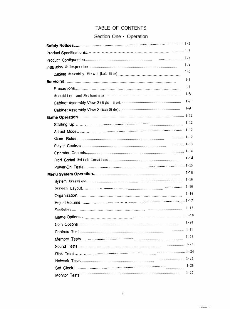
TABLE OF CONTENTS
Section One - Operation
Safety Notices ....................................................................................................l-2
Product Specifications.. . . . . . . . . . . . . . . . . . . . . . . . . . . . . . . . . . . . . . l-3. . . . . . . . . . . . . . . . . . . . . . . . . . . . . . . . . . . (,
Product Configuration ......................... l-3.................................................................
installation & Inspection ...................................................................................... l-4
Cabinet Assembly View 1 (Left Side) . . . . . . . . . . . . . . . . . . . . . . . . . . . . . . . . . . . . . . . . . . . . . . . . . . . l- 5
Semlclng.. .................................................................................................1-6
Precautions .............................................................................................. l-6
Assemblies and Mechanisms ....................................................................... l-6
Cabinet Assembly View 2 (Right Side). ......................................................... l-7
Cabinet Assembly View 2 (Back Side). ........................................................ l-9
Game Operath ................................................................................... ........... 1-12
Starting Up..........................................................~.......~ ................................ 1-12
Attract Mode .................................................................................................1-12
Game Rules ..................................................................................... ............ 1-12
Player Controls .................................................................................. ............ 1-13
Operator Controls .............................................................................. ........... 1-14
Front Control Switch Locations..................................................................... l-1 4
Power On Tests.............................................." .............................................. 1-15
Menu System Operation.. .................................................................................. l-1 6
System Overview 1-16................................................... .......................................
Screen Layout......................................~ .................................. .................. 1-16
Organization ............................................................................................. 1-16
Adjust Volume ............................................................................................ ..l-17
Statistics ................................. 1-18..................................................................
Game Options.. . .l-19. . . . . . . . . . . . . . . . . . . . . . . . . . . . . . . . . . . . . . . . . . .............................................
Coin Options ................................................................................................. l-20
Controls Test ................................................................................... ............ 1-21
Memory Tests..............................................." ................................................ l-22
Sound Tests .......................................................................... ................. 1-23
Disk Tests............................................................~ ............ ............. ............. l-24
Network Tests 1-25....................................................................... .........................
Set Clock.....................................................~............................." ..................1-26
................................................................................................. 1-27Monitor Tests
ii
Tournament Operation.. ....................................................................................l-28
Equipment Requirements ..............................................................................l-28
Tournament Example.. ............................................................................... l-28
Starting Up.. .............................................................................................l-28
Tournament Settings.. ................................................................................. l-29
DIP Switches and Jumpers.. ....................................................................... l-30
Section Two - Parts
Cabinet (Rear View). ........................................................................................... 2-2
Seat Assembly ........................................................................................... 2-3
Dashboard Assembly .................................................................................. 2-4
Steering Wheel and Pedal Assemblies 2-5......................,, ................................
CPU Board Assembly.. 2-6............................................. .................................
Motor Board Assembly................................................................................ 2-7
Audio Board Assembly ................................................................................ 2-8
Line Cord Application Chart.. ........................................................................2-g
Section Three - Cabinet Wiring _
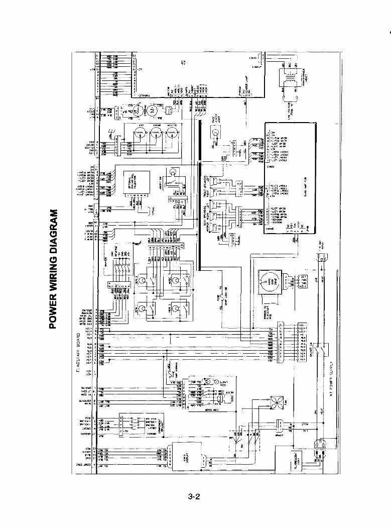
Power Wiring Diagram . . . . . . . . . . . . . . . . . . . . . . . . . . . . . . . . . . . . . . . . . . . . . . . . . . . . . . . . . . . . . . . . . . . . . . . . . . . . . . . . . . . . . . . . -3-2
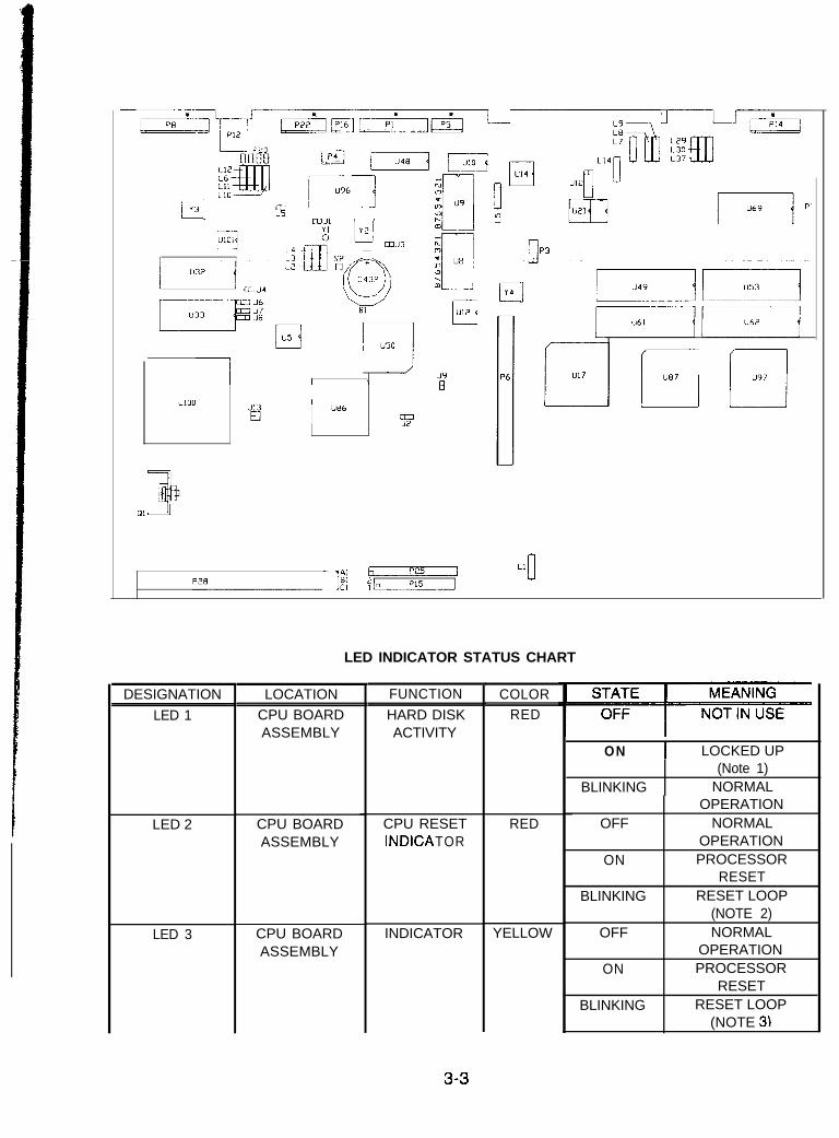
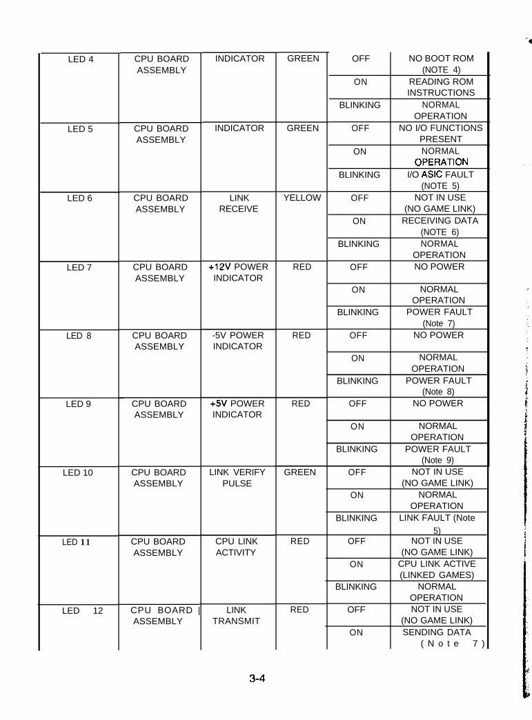
LED Indicator Status Chart (CPU Board Assembly) . . . . . . . . . . . . . . . . . . . . . . . . . . . . . . . . . . . . . . . . . . . . 3-3
LED indicator Status Chart (Motor Board Assembly) ..,,..................................... . 3-6
Section Four - Troubleshooting
Game Does Not Start ....................................................................................... 4-2
Game Can Not Be Played.. ............................................................................... .4-3
Player Control Problems .................................................................................. h-4
Audio problems ................................................................................................ 4-5
Video Problems.. ............................................................................................... 4-6
Miscellaneous.. ..............................................................................................4-7
. . .III
ATTENTIONPROPERLY ATTACH ALL CONNECTORS. Be sure that the connectors on each printed circuit board(PCB) are proper/y connected. If they do not slip on easily, do not force them. A reversed connectorcma dama e our ame and void the warran .
SETUP PROCEDURE
PRODUCT SPECIFICATIONS
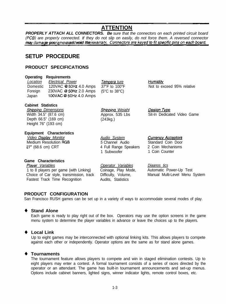
Operating RequirementsLocation Electrical PowerDomestic 120VAC @ 60Hz 4.0 AmpsForeign 230VAC @ 50Hz 2.0 AmpsJapan 100VAC @ 50Hz 4.0 Amps
Cabinet StatisticsShiooina DimensionsWidth 34.5” (87.6 cm)Depth 66.5” (169 cm)Height 76” (193 cm)
Equipment CharacteristicsVideo DisDlav MonitorMedium Resolution RGB27” (68.6 cm) CRT
Game CharacteristicsP/aver Variables1 to 8 players per game (with Linking)Choice of Car style, transmission, trackFastest Track Time Recognition
Temoera ture37°F to 100°F(5°C to 38°C)
Shiooina WeiahtApprox. 535 Lbs(243kg.)
HumiditvNot to exceed 95% relative
Des&n TvoeSit-In Dedicated Video Game
Audio Svstem Currencv Acceotors5 Channel Audio Standard Coin Door4 Full Range Speakers 2 Coin Mechanisms1 Subwoofer 1 Coin Counter
Operator VariablesCoinage, Play Mode,Difficulty, Volume,Audits, Statistics
Diaanos ticsAutomatic Power-Up TestManual Multi-Level Menu System
PRODUCT CONFIGURATIONSan Francisco RUSH games can be set up in a variety of ways to accommodate several modes of play.
4
4
4
Stand AloneEach game is ready to play right out of the box. Operators may use the option screens in the gamemenu system to determine the player variables in advance or leave the choices up to the players.
Local LinkUp to eight games may be interconnected with optional linking kits. This allows players to competeagainst each other or independently. Operator options are the same as for stand alone games.
TournamentsThe tournament feature allows players to compete and win in staged elimination contests. Up toeight players may enter a contest. A formal tournament consists of a series of races directed by theoperator or an attendant. The game has built-in tournament announcements and set-up menus.Options include cabinet banners, lighted signs, winner indicator lights, remote control boxes, etc.
1-3
INSTALLATION & INSPECTION
1.
2.
-3r
4.
5.
6.
7.
a.
Remove the straps from the shipping container. Lift the carton up and off of the game. Inspect theexterior of the cabinet and the seat for any damage.
The coin door keys are attached to the steering wheel. Unlock and open the coin door. The cashbox door and rear door keys are located on a key hook attached to the inside of the coin door.Unlock and open the cash box door. Remove the spare parts stored in the cash box.
Remove and save the screws at the top and sides of the [Far poor. Unlock the rear door, then lift itoff of the cabinet and set it aside. Inspect the cabinet interior for any signs of damage. Check allmajor assemblies to assure that they are mounted securely.
Use the seat adjust lever at the front of the seat to change the seat position. The seat must movesmoothly through the full range of adjustment and lock firmly in each detent position.
Refer to the Cabinet Wiring Diagram (Section 3), and check to see that all cable connectors arecorrectly secured. Do not force connectors; they are keyed to fit in only one location. Bent pins andreversed connections may damage your game and void the warranty.
Use a voltmeter to determine the line voltage. The power supply line voltage switch on the back, thetransformer and the fluorescent lamp ballast in the marquee must agree with the measured voltage.
AI WARNINGThe cabinet Is top heavy.
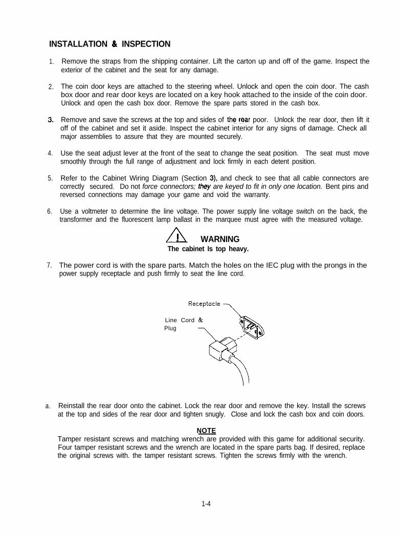
The power cord is with the spare parts. Match the holes on the IEC plug with the prongs in thepower supply receptacle and push firmly to seat the line cord.
Line Cord &Plug
Reinstall the rear door onto the cabinet. Lock the rear door and remove the key. Install the screwsat the top and sides of the rear door and tighten snugly. Close and lock the cash box and coin doors.
NOTETamper resistant screws and matching wrench are provided with this game for additional security.Four tamper resistant screws and the wrench are located in the spare parts bag. If desired, replacethe original screws with. the tamper resistant screws. Tighten the screws firmly with the wrench.
1-4
9. Move the game to its intended location. Lower each leg leveler until the cabinet is stable and level.Adjust the levelers as required to distribute weight equally on each corner.
10. Plug the game into a grounded (3-terminal) AC wall outlet. Switch ON the game, using the ON/OFFswitch located on the center left rear of the cabinet. The game will power up and begin self-diagnostics. If no errors are found, the game will automatically enter its “attract” mode of operation.
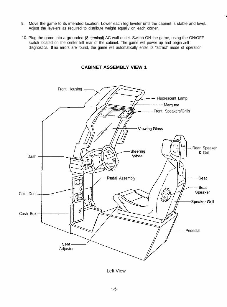
CABINET ASSEMBLY VIEW 1
Front Housing .-,m
Dash
- Fluorescent Lamp
Front Speakers/Grills
Rear Speaker& Grill
-T-I-- Pedal Assemblv
Adjuster
Coin Door
Cash Box
Pedestal
Left View
l-5
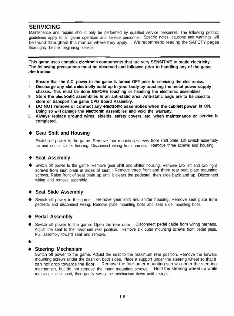
SERVICINGMaintenance and repairs should only be performed by qualified service personnel. The following productguidelines apply to all game operators and service personnel. Specific notes, cautions and warnings willbe found throughout this manual where they apply. We recommend reading the SAFETY pagesthoroughly before beginning service.
Thls game uses complex electronic components that are very SENSITIVE to static electricity.The following precautions must be observed and followed prior to handling any of the gameeiiXtronics;
1.2.
3.
4.
5.
+
+
+
+
+
+
+
+
+
Ensure that the A.C. power to the game Is turned OFF prior to servicing the electronics.Discharge any static electrlclty build up In your body by touching the metal power supplychassis. This must be done BEFORE touching or handling the electronic assemblies.Store the electronic assemblles In an anti-static area. Anti-static bags are to be used tostore or transport the game CPU Board Assembly.DO NOT remove or connect any electronic assemblies when the cabinet powerDolng so will damage the electronic assemblles and void the warranty.Always replace ground wlres, shlelds, safety covers, etc. when maintenance or
Is ON.
service Iscompleted.
Gear Shift and HousingSwitch off power to the game. Remove four mounting screwsup and out of shifter housing. Disconnect wiring from harness.
Seat Assembly
from shift plate. Lift switch assemblyRemove three screws and housing.
Switch off power to the game. Remove gear shift and shifter housing. Remove two left and two rightscrews from seat plate at sides of seat. Remove three front and three rear seat plate mountingscrews, Raise front of seat plate up until it clears the pedestal, then slide back and up. Disconnectwiring and remove assembly.
Seat Slide AssemblySwitch off power to the game. Remove gear shift and shifter housing. Remove seat plate frompedestal and disconnect wiring. Remove plate mounting bolts and seat slide mounting bolts.
Pedal AssemblySwitch off power to the game. Open the rear door. Disconnect pedal cable from wiring harness.Adjust the seat to the maximum rear position. Remove six outer mounting screws from pedal plate.Pull assembly toward seat and remove.
Steering MechanismSwitch off power to the game. Adjust the seat to the maximum rear position. Remove the forwardmounting screws under the dash on both sides. Place a support under the steering wheel so that itcan not drop towards the floor. Remove the four outer mounting screws under the steeringmechanism, but do not remove the inner mounting screws. Hold the steering wheel up whileremoving the support, then gently swing the mechanism down until it stops.
l-6
-4
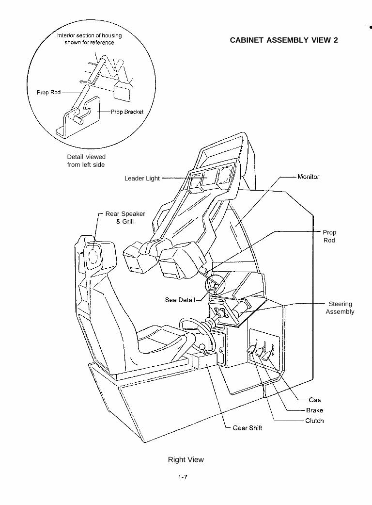
CABINET ASSEMBLY VIEW 2
Detail viewedfrom left side
Leader Light
Rear Speaker& Grill
- PropRod
- SteeringAssembly
Right View
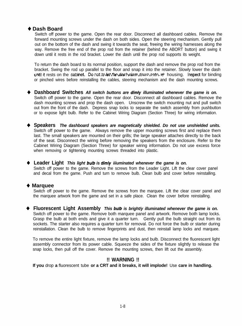
+ Dash BoardSwitch off power to the game. Open the rear door. Disconnect all dashboard cables. Remove theforward mounting screws under the dash on both sides. Open the steering mechanism. Gently pullout on the bottom of the dash and swing it towards the seat, freeing the wiring harnesses along theway. Remove the free end of the prop rod from the retainer (behind the ABORT button) and swing itdown until it rests in the rod bracket. Lower the dash until the prop rod supports its weight.
To return the dash board to its normal position, support the dash and remove the prop rod from thebracket. Swing the rod up parallel to the floor and snap it into the retainer. Slowly lower the dashuntii-it rests on the d3~&.
IT- -rb 4.. I-4 +krr An-h rlem An,.rn nn+n t huv I WI w ICL LI I= uaa 1 aan 11 uvvvg 1 vt IL” La ,e housing. !CSpEi for bindingor pinched wires before reinstalling the cables, steering mechanism and the dash mounting screws.
+ Dashboard Switches All switch buttons are dim/y illuminated whenever the game is on.Switch off power to the game. Open the rear door. Disconnect all dashboard cables. Remove thedash mounting screws and prop the dash open. Unscrew the switch mounting nut and pull switchout from the front of the dash. Depress snap locks to separate the switch assembly from pushbuttonor to expose light bulb. Refer to the Cabinet Wiring Diagram (Section Three) for wiring information.
+ Speakers The dashboard speakers are magnetically shielded. Do not use unshielded units.Switch off power to the game. Always remove the upper mounting screws first and replace themlast. The small speakers are mounted on their grills; the large speaker attaches directly to the backof the seat. Disconnect the wiring before removing the speakers from the enclosure. Refer to theCabinet Wiring Diagram (Section Three) for speaker wiring information. Do not use excess forcewhen removing or tightening mounting screws threaded into plastic.
+ Leader Light This light bulb is dim/y iiiuminated whenever the game is on.Switch off power to the game. Remove the screws from the Leader Light. Lift the clear cover paneland decal from the game. Push and turn to remove bulb. Clean bulb and cover before reinstalling.
+ MarqueeSwitch off power to the game. Remove the screws from the marquee. Lift the clear cover panel andthe marquee artwork from the game and set in a safe place. Clean the cover before reinstalling.
+ Fluorescent Light Assembly This bulb is bright/y illuminated whenever the game is on.Switch off power to the game. Remove both marquee panel and artwork. Remove both lamp locks.Grasp the bulb at both ends and give it a quarter turn. Gently pull the bulb straight out from itssockets. The starter also requires a quarter turn for removal. Do not force the bulb or starter duringreinstallation. Clean the bulb to remove fingerprints and dust, then reinstall lamp locks and marquee.
To remove the entire light fixture, remove the lamp locks and bulb. Disconnect the fluorescent lightassembly connector from its power cable. Squeeze the sides of the fixture slightly to release thesnap locks, then pull off the cover. Remove the mounting screws, then lift out the assembly.
!! WARNING !!If you drop a fluorescent tube or a CRT and it breaks, it will implode! Use care in handling.
1-8
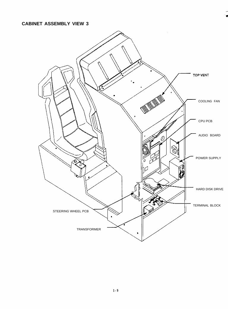
CABINET ASSEMBLY VIEW 3
STEERING WHEEL PCB
TRANSFORMER
COOLING FAN
CPU PCB
AUDIO BOARD
POWER SUPPLY
HARD DISK DRIVE
- II
TERMINAL BLOCK
1-9
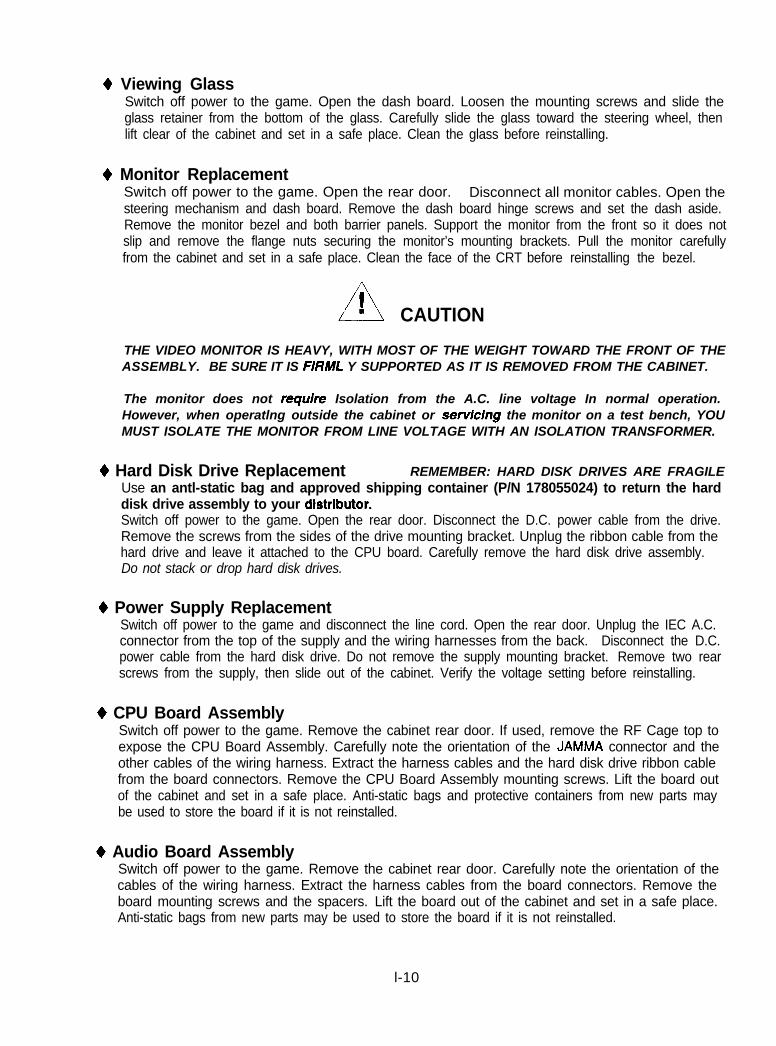
+ Viewing GlassSwitch off power to the game. Open the dash board. Loosen the mounting screws and slide theglass retainer from the bottom of the glass. Carefully slide the glass toward the steering wheel, thenlift clear of the cabinet and set in a safe place. Clean the glass before reinstalling.
+ Monitor ReplacementSwitch off power to the game. Open the rear door. Disconnect all monitor cables. Open thesteering mechanism and dash board. Remove the dash board hinge screws and set the dash aside.Remove the monitor bezel and both barrier panels. Support the monitor from the front so it does notslip and remove the flange nuts securing the monitor’s mounting brackets. Pull the monitor carefullyfrom the cabinet and set in a safe place. Clean the face of the CRT before reinstalling the bezel.
CAUTION
THE VIDEO MONITOR IS HEAVY, WITH MOST OF THE WEIGHT TOWARD THE FRONT OF THEASSEMBLY. BE SURE IT IS FIRML Y SUPPORTED AS IT IS REMOVED FROM THE CABINET.
The monitor does not require Isolation from the A.C. line voltage In normal operation.However, when operatlng outside the cabinet or servlclng the monitor on a test bench, YOUMUST ISOLATE THE MONITOR FROM LINE VOLTAGE WITH AN ISOLATION TRANSFORMER.
+ Hard Disk Drive Replacement REMEMBER: HARD DISK DRIVES ARE FRAGILEUse an antl-static bag and approved shipping container (P/N 178055024) to return the harddisk drive assembly to your distributor.Switch off power to the game. Open the rear door. Disconnect the D.C. power cable from the drive.Remove the screws from the sides of the drive mounting bracket. Unplug the ribbon cable from thehard drive and leave it attached to the CPU board. Carefully remove the hard disk drive assembly.Do not stack or drop hard disk drives.
+ Power Supply ReplacementSwitch off power to the game and disconnect the line cord. Open the rear door. Unplug the IEC A.C.connector from the top of the supply and the wiring harnesses from the back. Disconnect the D.C.power cable from the hard disk drive. Do not remove the supply mounting bracket. Remove two rearscrews from the supply, then slide out of the cabinet. Verify the voltage setting before reinstalling.
+ CPU Board AssemblySwitch off power to the game. Remove the cabinet rear door. If used, remove the RF Cage top toexpose the CPU Board Assembly. Carefully note the orientation of the JAMMA connector and theother cables of the wiring harness. Extract the harness cables and the hard disk drive ribbon cablefrom the board connectors. Remove the CPU Board Assembly mounting screws. Lift the board outof the cabinet and set in a safe place. Anti-static bags and protective containers from new parts maybe used to store the board if it is not reinstalled.
4 Audio Board AssemblySwitch off power to the game. Remove the cabinet rear door. Carefully note the orientation of thecables of the wiring harness. Extract the harness cables from the board connectors. Remove theboard mounting screws and the spacers. Lift the board out of the cabinet and set in a safe place.Anti-static bags from new parts may be used to store the board if it is not reinstalled.
l-10
+ Motor Board AssemblySwitch off power to the game. Remove the cabinet rear door. Carefully note the orientation of thecables of the wiring harness. Extract the harness cables from the board connectors. Remove theboard mounting screws and the spacers. Lift the board out of the cabinet and set in a safe place.Anti-static bags from new parts may be used to store the board if it is not reinstalled.
A ! CdlJTlON Allow adequate time for cooling before handling board.Heatsink and power resistors may get very hot during normal operation.
;~~~ ~~~~~ ~~~~~~ ~~~~~ ~~~~~~~ ~~ ~~~~ ~~~~~~0
+ Memory Replacement
!
The ROM (Read Only Memory) circuits contain the computer operating instructions. Memory devicesare especially sensitive to static charges. Use grounding precautions when handling these parts.
Switch off power to the game. Carefully note the position, then remove using a chip extraction tool.
To reinstall memory circuits, orient a chip over its socket and press firmly to seat pins. Do not force.
A! CAUTION Discharge any static electricity build up in your body bytouching the power supply chassis. This is to be done BEFORE touchingor handllng the electronic assemblies.
+ Battery ReplacementSwitch off power to the game. Carefully note the position, then gently lift the contact arm to releasetension. Do not bend the arm. Slight finger pressure may be needed to pry the cell from its holder.
To reinstall the battery, orient cell near its holder and slide it in under the contact arm. Do not force.
A! CAUTION Danger of explosion if battery is incorrectly replaced.Replace only with the same or equivalent type recommended by themanufacturer. Dispose of used batteries according to instructions printedon the battery or the manufacturers packaging.
1-11
GAME OPERATIONSTARTING UPEach time the game is first turned on or power is restored, it begins executing code out of the boot ROM.These self-diagnostic tests automatically verify and report condition of the hardware and the disk drive. Ifany of the individual tests fails, then an error message will be displayed for each test. Record allmessages before starting game. The message will be displayed until the ABORT button is pressed.
* If no buttons are pressed, the system will quickly complete all tests then load and run the game.l Press and hold the coin door TEST button to skip the boot ROM tests and activate the Menu System.
Once all Power-up tests have been passed, the game goes into ATTRACT MODE. Scenes and soundsfrom a typical game are alternated with previous track times in endless repetition until game play starts.
ATTRACT MODEBefore the game starts, the ATTRACT screens show scenes and sounds from typical races on each ofthe tracks. Alternating with these scenes are views of the cars, best track times, game production teamacknowlegements, etc. The attraction screens cycle endlessly until a player or operator starts the game.
The operator can choose to add more ATTRACT screens to the standard presentation.
+ The “WIN RACE FOR A FREE GAME” message will display the in ATTRACT MODE if Free Gamesetting is chosen as the WINNER OPTIONS menu item (refer to COIN OPTIONS in this section).
+ The “ASK ATTENDANT ABOUT RUSH TOURNAMENT’ message will display the if the On setting ischosen as the TOURNAMENT INFO SCREEN menu item (refer to GAME OPTIONS in this section).
GAME RULESINDIVIDUAL PLAYChoose any cabinet. Insert currency to start the game. Player selects from the required game variables:
1. The player selects a track. Each track has a different skill level and quantity of checkpoints.2. The player selects from several cars. Each car has different handling capabilities.3. The player selects automatic transmission (no shifts) or manual transmission (clutch optional).
HEAD TO HEAD PLAYChoose a linked cabinet. Insert currency at JOIN IN message. There are now some restricted choices:
1. The players select tracks. All tracks are available, but all players must choose the same track.2. The players select from several cars. Each car has different handling capabilities..3. The players select automatic transmission (no shifts) or manual transmission (clutch optional).
TOURNAMENT PLAYChoose a tournament cabinet. Payment and restrictions are controlled by the operator or attendant:
1. One track is selected. All tracks are available, but all players must choose the same track.2. Cars are chosen. The operator may intentionally limit the range of player choices if desired.3. Transmission type can be fixed for each tournament or left to player discretion.
1-12
PLAYER CONTROLS
VIEW 1 ButtonThe View 1 button gives the players the ability to see the race area from the front of the car.Press and hold the View 1 button during car selection to see additional car styles.
VIEW 2 ButtonThe View 2 button gives the players the ability to see the race area from inside the car.Press MUSIC and VIEW 2 together during car selection to remove all drone cars from the track.
VIEW 3 ButtonThe View 3 button gives the players the ability to see the race area from above and behind the car.Press MUSIC and VIEW 3 together during car selection to reset steering wheel force values.
MUSIC ButtonThe MUSIC button changes the sounds heard during the game. Each press selects another station.Press MUSIC in combination with the VIEW buttons during to display more options.
ABORT ButtonThe ABORT button allows immediate game play interruption. The car recovers from fatal mistakes.Press ABORT to return to the road and continue. (Refer to CATCHUP on TOURNAMENT screen.)
REVERSE ButtonPress the REVERSE button at any time to change the direction of the drive wheels rotation.Press REVERSE to remove computer controlled cars (drones) during track selection (SOLO).
GEAR SHIFTThe GEAR SHIFT allows the player to select the best gear for acceleration, cruising, or deceleration.The GEAR SHIFT does not function during the race if automatic transmission has been selected.
STEERING WHEELThe Steering Wheel is used to aim the car during the race. It provides road feedback to the player.The Wheel is also used to choose car style, transmission type, track, etc., during game setup.
GAS PedalThe Gas pedal is used to control the car speed during the race.The same pedal is used to select car style, transmission type, track, etc., during game setup.
BRAKE PedalThe Brake pedal is used to slow or stop the car during the race.
CLUTCH PedalThe Clutch pedal is used for manual gear shifts. It has no function if automatic transmission is used.The manual transmission has synchronous gears to permit shifts without using the clutch if required.
SEAT ADJUSTERPull the SEAT ADJUSTER lever to the left until the seat moves freely, then slide the Seat as required.Release lever and rock back and forth slightly to set a detent position. This locks the Seat location.
l-13
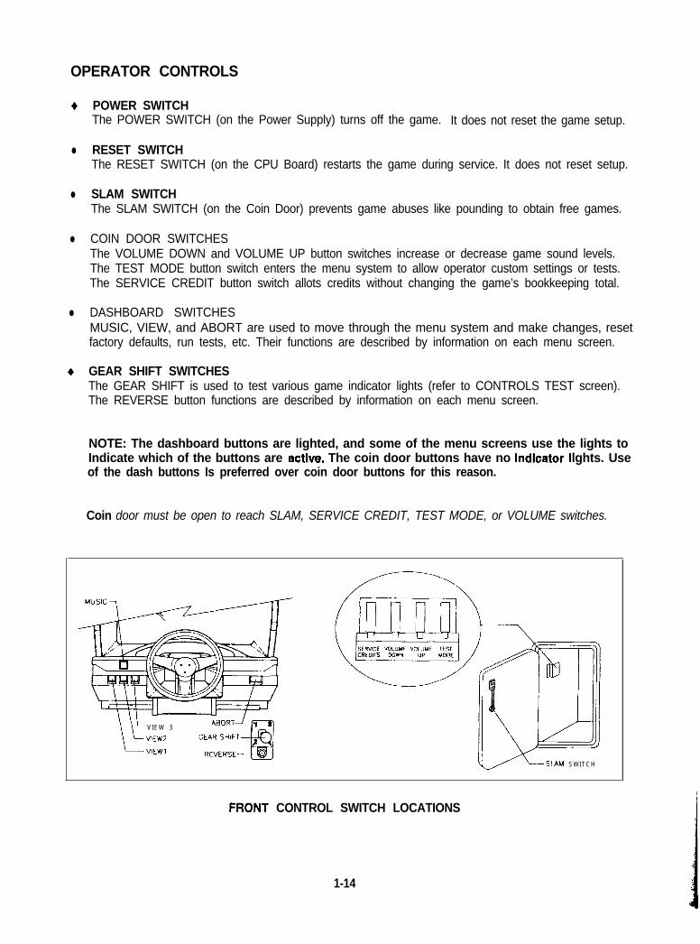
OPERATOR CONTROLS
+
l
l
l
l
+
POWER SWITCHThe POWER SWITCH (on the Power Supply) turns off the game. It does not reset the game setup.
RESET SWITCHThe RESET SWITCH (on the CPU Board) restarts the game during service. It does not reset setup.
SLAM SWITCHThe SLAM SWITCH (on the Coin Door) prevents game abuses like pounding to obtain free games.
COIN DOOR SWITCHESThe VOLUME DOWN and VOLUME UP button switches increase or decrease game sound levels.The TEST MODE button switch enters the menu system to allow operator custom settings or tests.The SERVICE CREDIT button switch allots credits without changing the game’s bookkeeping total.
DASHBOARD SWITCHESMUSIC, VIEW, and ABORT are used to move through the menu system and make changes, resetfactory defaults, run tests, etc. Their functions are described by information on each menu screen.
GEAR SHIFT SWITCHESThe GEAR SHIFT is used to test various game indicator lights (refer to CONTROLS TEST screen).The REVERSE button functions are described by information on each menu screen.
NOTE: The dashboard buttons are lighted, and some of the menu screens use the lights toIndicate which of the buttons are active. The coin door buttons have no lndlcator Ilghts. Useof the dash buttons Is preferred over coin door buttons for this reason.
Coin door must be open to reach SLAM, SERVICE CREDIT, TEST MODE, or VOLUME switches.
V I E W 3
VIEW2
VIEWI
v \SLAM SWITCH
.FRONT CONTROL SWITCH LOCATIONS
1-14
POWER ON TESTSThe Power On Tests let the game calibrate the player controls. Do not touch the wheel during test.
Use the ABORT button to cancel these tests. Allow the tests to complete at least once before aborting.
POWER ON TESTS SCREEN
The test routine runs whenever power is switched off and on or in cases where there is a processorreset. This prevents system calibration errors to the critical player controls.
These basic tests run automatically; their purpose is to detect those faults which would prevent the gameor the menu system from operating properly. Steering wheel and pedal positions are checked forposition and function. Messages appear on screen as each item is run, along with any errors detected.
A successful self-test usually takes less than one minute to complete. Write down any messages beforeproceeding to the menus or game play.
After the above screen is displayed, the system will turn the steering wheel to each of its extremes andindicate the maximum and minimum position values. Do not touch the wheel or pedals during thiscalibration routine. Dirt, debris, binding, or loose parts may cause errors to be detected by this routine.
Errors may be diagnosed more thoroughly by manual testing (refer to CONTROLS TEST in this section).
During service or repair, power may be disrupted and restored repeatedly. Each break in power willcause these tests to be run again. After the first time, press ABORT to skip any unwanted tests.
NOTE: When the Tournament mode Is active, the Tournament menu screen will immediatelyfollow the Power On Tests screen. If changes are required to the tournament features, refer tothe TOURNAMENT screen instructions later in this section. If no changes are required,chooseSAVE to exit from this screen and return to game play.
1-15
MENU SYSTEMSYSTEM OVERVIEWGame variables and diagnostics are presented in a series of on-screen menus. The Main Menu screenallows the operator to view information, make changes, or verify equipment operation. Each Sub Menuscreen displays one specific group of choices. The Detail Menu presents data or runs the required test.You must be at the Detail Menu level to detect errors, make changes, or activate tests. Both the operatorcontrols and the player controls are used to move through the menus and start or stop particular routines.
SCREEN LAYOUTEach menu screen is different, but the material presented stays in the same physicai iocation each time.
The color bar at the top center of each screen displays the current menu title.The center of the screen is used for data (menu items, video signals, statistics, reports, etc.)The bottom of the screen is reserved for messages (control functions, revision levels, etc.)
ORGANIZATIONMain Menu screen items fall into two categories: options and tests. Items must be activated manually.
Sub Menu screen items offer the operator choices within a category. Some items have no Sub Menuwhile others may have more than one. You can get back to the previous menu or go on to the next menu.
Detail Menu screen items contain specific information. The operator must interact with the system to getresults or to make changes. There is always a way to go back to the previous menus from this screen.
Use the control indicated to highlight an item on any menu. On/v one hiuh/iuhted item can be selected ata timeA To return the game to normal, select EXIT TO GAME, then press the indicated button.
TYPICAL SELF TEST MENU SCREEN
l-16
F
ADJUST VOLUMEThe Adjust Volume feature allows the operator to determine the sound and music levels of the game.
The volume level can be adjusted for either the Attract Mode or the Game. Press the MUSIC button toraise the volume level or the VIEW 2 button to lower the volume level. Music is played continuously whilethis screen is active.
Game Volume level may be adjusted without going through the menu system. Open the coin doorand use the VOLUME UP and VOLUME DOWN buttons of the Coln Door Switches durlng a game.
ADJUST VOLUME MENU SCREEN
The “Game” volume is continuously adjustable from zero to maximum. The game will seem morerealistic if the player experiences high volume sounds during play (race cars are not quiet in operation).
The “Attract” volume only has four levels of adjustment: Mute (zero), l/3, 2/3, or Full. For greater profits,adjust your volume levels to a loud setting to draw attention to this game.
The current volume level is represented by the length of a bar made of asterisks. A longer bar indicatesa higher volume setting than a short bar. Factory default for ‘Game” volume levels is 50%, “Attract” 2/3.
The “Attract” and ‘Game” volume levels may be adjusted to different values, but the “Attract” level cannotbe set higher than the level chosen for normal game play. If the “Game” level is lowered, it willautomatically lower the “Attract” level. Lowering the “Attract” level will not effect the ‘Game” volume.
Be certain to press only the REVERSE button when any volume adjustments are made. The ABORTbutton will cancel any settings on the screen and return both levels to the previous screen values.
NOTE: These adjustments affect the volume of the tests as well as the game play. If the volumelevels are set to minimum (zero), there will be no sounds form the speakers during any of theaudio tests. It is recommended that the volume levels be set to a moderately high value each timethe sound portion of the game is checked. The levels may be returned to their previous settingsafter the tests have been completed.
1-17
STATISTICSThe Statistics report allows the operator to assess how often and how well the game is being played. Inaddition to the earnings, various game aspects are tracked to determine the players skill levels.
Use the MUSIC and VIEW #2 buttons to select a particular menu item. The VIEW #I and #3 buttons areused to change values. The statistics may be reset to zero or allowed to increase after each viewing.
STATISTICS REPORT MENU SCREEN
The illustration shows how the report screen will look after the game has been reset or is first turned on.Most of the statistics will increase in value as the game is played. It is normal for some values to remainat zero: for example, the Earned Games count will not change unless the cabinet has been set up forfree games, and the Error count will not change if no errors have occurred.
Low counts in both coin and player statistics may indicate that the game is too difficult for the skill levelsof the players at this location. High counts may result if Bonus or Winner Option menu items are ineffect. The difficulty level and other play characteristics may be adjusted from the Game Options menu.
It is recommended that the Statistics be recorded before any service or repairs are done on this game.
Press only the REVERSE button to view the additional game statistics. Press REVERSE and ABORTtogether to cancel any changes on the screen and return all numbers to the factory default values.
The HISTOGRAMS screens will have no bar graphs until the system has enough data to plot.
The USER MSGS screen will contain no messages until the system detects an error.
1-18
GAME OPTIONSThese adjustments allow the operator to customize the game. Each of the variables will change someaspect of game appearance or play. Optimum settings cause high player interest and increase earnings.
Use the MUSIC and VIEW #2 buttons to select a particular menu item. The VIEW #l and #3 buttons areused to change variables. Options may be reset to factory default values or changed after each viewing.
GAME OPTIONS MENU SCREEN
The illustration shows how this screen will look with all of the factory default settings. Each press of theVIEW #1 or #3 buttons will advance a variable through its range of choices. Some items have moreoptions than others. It is recommended that all of them be examined before one is selected.
The effects of these options can be judged by comparing statistics reports before and after changes weremade. As players become more familiar with the game, you can add new features or increase difficulty.
Turning ON Tournament Setup activates a new screen (refer to TOURNAMENT screen in this section)upon exiting the menu system. The operator may then select options not required for one player games.NOTE: The Tournament features may be turned off from the TOURNAMENT screen by sekrhgCANCEL to exit. This turns Tournament Setup to OFF on this menu screen at the same rime.
Language changes the player information during game play. It does not change menu screens or tests.
Turning ON Tournament Info Screen sends a player message “Ask attendant about RUSH tournament”.
1-19
COIN OPTIONSThe Coin Options are used to set up the coin mechanisms and set the pricing of the games. Factorydefauit values can be considered standard.
Use the MUSIC and VIEW #2 buttons to select a particular menu item. The VIEW #l and #3 buttons areused to change variables. Options may be reset to factory default values or changed after each viewing.
PRICING OPTIONS MENU SCREEN
MECH SETUP MENU SCREEN
The illustrations show how these screens will look with all of the factory default settings. Each press ofthe VIEW buttons will advance a variable through its range of choices. Some items have more optionsthan others. It is recommended that all of them be viewed before one is selected.
PRICING OPTIONSCustom pricing sets credits required to start and continue a game, rewards for buy-in and winning, etc.There are no other options if free play is selected. Free aame olaver incentives will reduce earninas.
MECH SETUPMech setup permits the operator to add or remove coin or bill mechanisms. Although values are shownfor all devices, changes to unused inputs will have no effect if there is no such mechanism in the game.
l-20
CONTROLS TESTThese tests allow the operator to manually check each switch in the game.
NOTESome switches may nor be used with this game. Check the wiring diagram and the mech setup items.
Use the MUSIC and VIEW #2 buttons to select a particular menu item. The VIEW #l and #3 buttons areused to change variables. Activate each switch and the indication on the screen changes state. Releasethe switch and the indicator returns to its previous condition. Switches may be tested in any combination.
CONTROLS TEST MENU SCREEN
The Controls are shown on the screen as they are found on the dash, gearshift, coin door bracket, etc.Each control change should be exactly duplicated by a single indication on the menu screen.
The Controls Test screen is used to verify crossed wires, intermittent conditions, and stuck switches.
Press and hold ABORT to test the Steering Wheel force. Restrain the wheel with one hand during test.The force will increase to maximum and decrease to minimum, then change directions and repeat again.
Press and hold TEST MODE to set the pedal travel limits. Depress and release each pedal during test.The digital indicator numbers change each time the computer detects a new position for each pedal.
Note and record the Coin Counter reading before beginning the test to avoid subsequent count errors.Press the Coin Door Slam Switch to increase the count by one digit. Do nor bend S/am Switch contacts.
NOTE: The LEADER light illuminates when shifting into first gear (1) and off in ail other gears.The optional WINNER light iiiuminates when shifting into third gear (3) and off in ail other gears.ABORT, MUSIC and VIEW buttons are brightly illuminated when pressed and dim In other tests.
1-21
MEMORY TESTSThe Memory Tests allow the operator to verify some of the functions of the CPU Board Assembly RAM.
NOTEThese tests detect system errors, not actual game errors. The game program is on the Hard Disk Drive.
Use the MUSIC and VIEW #2 buttons to select a particular menu item. The VIEW #l and #3 buttons areused to choose another menu item. There are no custom settings or adjustable variables in these tests.
QUICK RAM TEST MENU SCREEN
FULL RAM TEST MENU SCREEN
WORKING RAM (QUICK) performs a fast check of the storage area for the game variables.The results of the test will be reported as pass or fail messages; error messages may be included.
WORKING RAM (FULL) performs a more thorough check of the storage area for the game variables.The results of the test will be reported as pass or fail messages; error messages may be included.
ROM TEST performs a fast check of the storage area for the game instruction set.The results of the test will be reported as pass or fail messages: error messages may be included.
NOTE: The memory tests here store the data required to permit player Interaction with the game.Audio memory Is tested separately (refer to the AUDIO CHECKSUMS screen In SOUND TESTS).
l-22
SOUND TESTSThese tests verify that the audio components are connected and operating properly.
NOTEThe level must be turned up for the speakers to be heard. Check the volume setting before testing.
Use the MUSIC and VIEW #2 buttons to select a particular menu item. The VIEW #l and #3 buttons areused to change variables. There are no custom settings or adjustable variables in these tests.
SPEAKER TEST MENU SCREEN
AUDIO CHECKSUM MENU SCREEN
AUDIO SPEAKER TEST sends alternating left and right voice sounds to the individual front and rearspeakers. The voices should be clear and distinct from each other. Each voice must come from thelocation identified. Press ABORT to test seat speaker. Refer to ADJUST VOLUME screen if necessary.
The Audio Speaker Test screen is used to verify crossed connections, incorrect phase, and distortion.
AUDIO CHECKSUMS are a series of diagnostic routines which analyze the digital sound circuits. Theresults of the tests will be reported as pass or fail messages; sounds may also accompany the tests.
The Audio Checksums are useful in locating digital circuit difficulties, especially when there is no soundfrom the speakers with the volume set at high levels. These tests detect sound memory problems.
l-23
DISK TESTSThe Disk Tests allow the operator to verify the functions of the Ha.rd Disk Drive Assembly.
Use the MUSIC and VIEW #2 buttons to select a particular menu item. The VIEW #l and #3 buttons areused to change variables. There are no custom settings or adjustable variables in these tests.
Hard Drive ConnectedDRIVE TEST MENU SCREEN
This test routine verifies the interface between the CPU Board Assembly and the Hard Disk Drive itself.The processor requests disk information. Data cannot be retrieved successfully if there is a problem.
Drive IDThis line gives an industry standard identification of the Hard Disk Drive. This is a manufacturerhardware number only; it will not identify the software or the game program stored on the drive assembly.
Sector TestThis test will perform a sector by sector read/verify test on the disk drive. As the status of each block ofsectors is checked, the speed of the data transfer is compared to its acceptance limits.
Tests Completed.These tests run over and over. The number increases each time the cycle repeats (approx. 4 minutes).
Checking FileFILE SYSTEM MENU SCREEN
This routine will perform a file by file check of data stored on the hard disk drive and report its findings.If errors are detected the system tries to fix them, then checks files again (approx. 5 minutes per cycle).
l-24
NETWORK TESTSThe Network Tests provide routines for verifying the communication circuits when games are linked.
Use the MUSIC and VIEW #2 buttons to select a particular menu item. The VIEW #1 and #3 buttons areused to choose another menu item. There are no custom settings or adjustable variables in these tests.
NETWORK TESTS MENU SCREEN
Several different options allow cabinets to be linked together for tournament type player competition.This screen allows the operator to determine if the linking equipment is networking or not working. Theresults of these tests either confirm proper operation or indicate where the problem may be found.
NOTE: This group of tests checks only system hardware (cables and communications circuits).Inspect for disconnected or broken cable, hubs, etc. individual games are not affected by faults.
Testing LocalThis test performs an internal check of the local communication circuits in the game cabinet. It does nottest any cables, hubs, or the other game cabinets. An error message indicates CPU board difficulties.
Testing CableThis verifies complete signal paths. “??‘I is a normal response to this test when the game is not linked.Linked games require all cabinets, couplers, hubs, etc. to be powered ON and connected to report OK.
Testing LinkThis sends data and looks for responses. At least two cabinets must be networked to pass this test.
Game and Car IDLinked games can not proceed if two or more cabinets are set up with the same car color. This reportlocates the identical cars. The operator must change one of them to avoid game conflicts.
TransmittedThis number is a running count of the data packets sent by each game cabinet. It increases until you exitthis screen. The local game location (your cabinet) is always listed first in the report.
ReceivedThis number is a running count of the data packets aquired from the network. It increases until you exit.All cabinets must be receiving packets from the local cabinets or the communications network is faulty.
l-25
SET CLOCKThe Set Clock screen allows the time and date to be entered accurately.
Use the MUSIC and VIEW #2 buttons to select a particular menu item. The VIEW #l and #3 buttons areused to change the variables. There are no custom settings or factory default values for these items.
SET CLOCK MENU SCREEN
The clock is used to provide accurate game statistics. The clock does not affect the game operation.
Once set, the clock will run until the battery dies or circuits are disrupted by service or some major fault.Periodically examine the top lines of the SELF TEST screen-for the correct time and date.
Press REVERSE to save new information. The ABORT button returns items to the previous values.
NOTE: The SELF TEST menu screen shows the time only when requested (not running time).
YearTwo digits. Range 00 to 99.
MonthTwo digits. Range 01 to 12.
DateTwo digits. Range 01 to 31.
DayOnly one digit. Range 1 to 7.
HourTwo digits. Range 00 to 23.
MinuteTwo digits. Range 00 to 59.
SecondTwo digits. Range 00 to 59.
l-26
MONITOR TESTSThe Monitor Tests provide patterns for verifying the monitor performance or making adjustments.
Use the MUSIC and VIEW #2 buttons to select a particular Game item. The VIEW #l and #3 buttons areused to change variables. There are no custom settings or adjustable variables in these tests.
MONITOR TESTS MENU SCREEN
COLOR BARS fills the screen with shades of colors to verify red, green, blue and white level dynamicadjustments. Each color bar should appear sharp, clear, and distinct from bars on either side.
Press the ABORT button two times to change the color of the screen border. Press REVERSE to exit.
The Color Bars screen is useful in adjusting the monitor brightness and contrast.
CONVERGENCE tests fill the screen with a grid and a series of dots. The grid and the dots should be allone color, with no fringes or parallel images. The lines should be straight and the dots round.
Press the ABORT button two times to change the color of the screen grid lines. Press REVERSE to exit.
The Convergence tests are useful in verifying the monitor convergence, linearity, and dynamic focus.
PURITY tests fill the screen with 100% of the chosen color at normal intensity. Each screen should beabsolutely uniform from top to bottom and side to side. No retrace lines or noise should be visible.
Press the ABORT button eight times to change the color of the screen. Press REVERSE to exit.
The Purity tests are useful in verifying monitor intensity, black level, blanking and degaussing.
RECTANGLES tests display solid color boxes over a contrasting background screen. The rectangleshould be centered with all four sides visible. The sides of the background should not be visible.
Press the ABORT button two times to change the color of the screen. Press REVERSE to exit.
The Rectangles tests are useful in verifying scan size and screen uniformity.
If any of the tests shows a need for adjustment, use the proper knobs on the Monitor Controls board.
l-27
‘a
TOURNAMENT OPERATIONEQUIPMENT REQUIREMENTSSeveral cabinets can be connected together and operated in Tournament Mode. The maximumconfiguration would consist of eight linked cabinets, the minimum requires only two. The Tournamentprogram may be turned off or on at will, so each cabinet can be set ‘up to meet the needs of the players.
Each cabinet must share data with the other cabinets in a Tournament. Two kits are available for this:+ Standard kits contain a crossover coupler. This passive device connects two cabinets together.6 Deluxe kits contain a network hub. This active device connects from two to eight cabinets together.
Cabinets must be communicating before Tournament Mode is available (refer to NETWORK TESTS).
TOURNAMENT EXAMPLEBefore the contests begin, turn on the Tournament Info Screen to let the players know about the event.At the appointed hour, the operator clears the area and sets all linked cabinets up in Tournament Mode.Rules are discussed and decisions are made concerning track, car color, difficulty level, laps, etc.The tournament may be started on a verbal command or remotely from the optional control box.Winners of the round are posted and losers are eliminated from the next level of competition.As fewer contestants remain in the final races, unneeded cabinets may be returned to normal game play.At the end of the tournament, the Tournament Mode and Info Screen are turned off for regular games.
STARTING UPThe Tournament screen allows operators or players to set up games in Tournament Mode. The gamesmust be linked together electrically to permit information sharing between the active games.
Active buttons are brightly lit. Use the MUSIC and VIEW buttons to select or change Tournament items.The ABORT button is used to highlight items. Choose one of the exit menu items to return to the game.
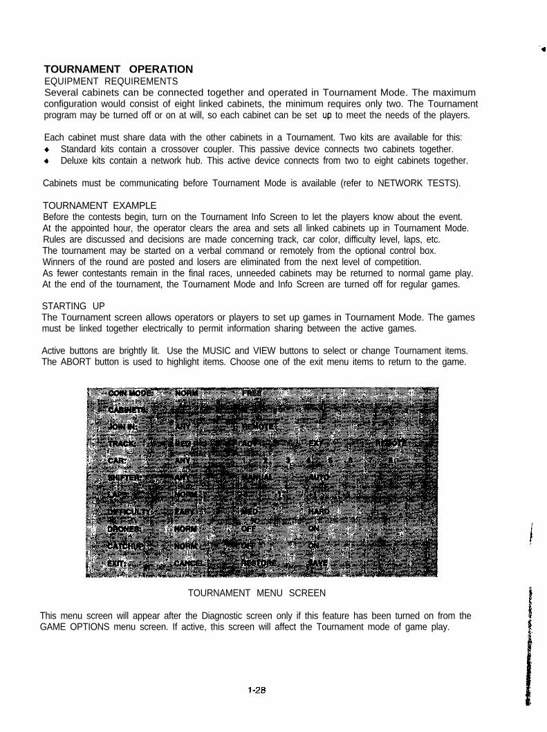
TOURNAMENT MENU SCREEN
This menu screen will appear after the Diagnostic screen only if this feature has been turned on from theGAME OPTIONS menu screen. If active, this screen will affect the Tournament mode of game play.
l-28
TOURNAMENT SETTINGS
COIN MODE may be set to FREE if the players will pay in advance to participate in a tournament. TheNORM setting means that players must all insert coins and choose to play at the same time.
CABINETS shows the number of linked games available in the network. Press the ABORT button toselect or deselect cabinets. Highlighted games are set up for tournament play. Range is 1 to 8.
JOIN IN determines which games are active in a tournament. ANY sends a message during setup butleaves participation up to each player. REMOTE allows the external contra! box to choose particjpants
TRACK sets which course is used for competition. Separate tracks are required for each tournament.One track can be fixed for each tournament, or REMOTE permits selection only from the control box.
CAR fixes the car style to avoid giving advantages to players who pick the fastest or best handling car.The ANY setting leaves the selection of cars up to the players.
SHIFTER sets the transmission type. Select MANUAL shifts for players who have clutch experience.The AUTO setting forces automatic shifts. As before, ANY leaves shift choices to the players.
LAPS allows the operator to fix the race distance. This permits the operator to shorten or lengthenraces. Choose -5 or -1 for fewer laps, +l or +5 for more laps (30 max.). NORM retains the checkpoints.
DIFFICULTY adjusts the skill level required to compete. Tournament cabinets must use the same level.Increase the difficulty level to present more challenge for the winning players as tournaments progress.
DRONES are the cars controlled by the computer. Select OFF to see only active players on the track.Drones ON fixes the computer controlled car color at gray to distinguish them from tournament players.
CATCHUP permits players to make mistakes and still win. OFF ensures realism (no second chances!).ON allows lagging cars to gain on the leader for a close finish. NORM allows catchup from an ABORT.
EXIT allows the operator three ways of returning the cabinet to game play and leaving this screen.Choose CANCEL to end tournaments and return to regular games. The Tournament screen disappears.RESTORE deletes changes to this tournament screen and brings back the previous tournament setup.SAVE places any new information on this screen in memory and permits games in Tournament Mode.
NOTE: Default values (Indicated as NORM or ANY) for this screen reflect operator or playerchoices each tlme a new game Is started. Selection of other values from thls screen will overrideprevious operator and player choices. Select REMOTE only to use the external control box.
l-29

DIP SWITCHES AND JUMPERS
The CPU Board has a number of hardware variables which can be changed to adapt this assembly toother uses. Jumpers determine which circuit paths are active, and DIP switches select instructions.
DIP Switches
There are two blocks of DIP Switches (U8 and U9) on this CPU Board set. Each block consists of eightindividual switches. Each switch enables or disables one program instruction.
NOTE: All lnstructlon variables for this game are software selectable from the menu system.Each DIP Switch should be set to Its OFF position (Factory default) for proper program operation.
Jumpers
There is one block of jumpers (P20) on this CPU Board set. The other jumpers are individual pins. Onlyone jumper (J9 - Sync Polarity) is installed on the board. This jumper is only for non-standard monitors.
NOTE: The circuit paths have been optimized at the factory during the board test procedure.Each jumper should be out (disconnected) to avoid error messages or video sync problems.
NOTES
l-30
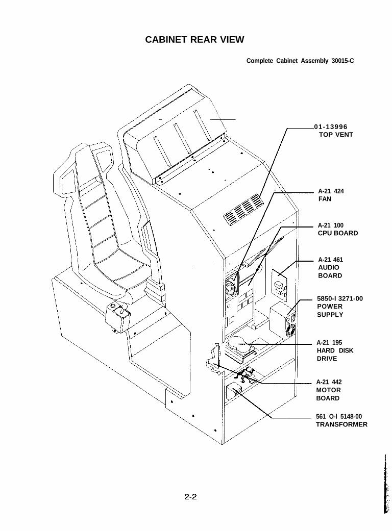
CABINET REAR VIEW
Complete Cabinet Assembly 30015-C
01-13996TOP VENT
A-21 424FAN
A-21 100CPU BOARD
A-21 461AUDIOBOARD
5850-l 3271-00POWERSUPPLY
A-21 195HARD DISKDRIVE
A-21 442MOTORBOARD
561 O-l 5148-00TRANSFORMER
2-2
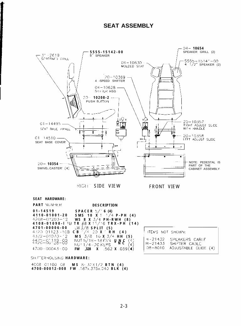
SEAT ASSEMBLY
-31-2619 i
04- 1 0 6 5 4
r5 5 5 5 - 1 5 1 4 2 - 0 0 SPEAKER GRILL (2)8” SPEAKER
3333--13141--v”
4-l/2” SPEAKER (2)
4 -SPEED SHIFTER
SMFTER HSG
20- 1 0 2 0 8 - 2 -PUSH BUrrOh
SEAT BASE COVER
20- 1 0 3 5 4SWIVEL CASTER
RIGIHT S IDE V IEW FRONT VIEW
NOTE: PEDESTAL ISPART OF THECABINET ASSEMBLY
SEAT HARDWARE:
P A R T NlJMBER DESCRIPTION
0 1 - 1 4 5 1 9 S P A C E R 5/l 6 (4)4 1 1 0 - 0 1 0 0 1 - 2 04208--01203-12
S M S 1 0 X l-1/4 P - P H ( 4 )W S 8 X 3/4 P H - R W H ( 8 )
4420-00128-00
4700~~00043-00
;“T ,,4_20 & “ N C [“i
FW ,328 X .562 X ,059 4
4
4 1 0 8 - 0 1 0 9 8 - l 1B T R #8 X 11,‘16 T R X - P H ( 1 4 )4 7 0 1 - 0 0 0 0 6 - 0 0 LW 3,‘8 S P L I T ( 5 )4323 -01123-16B C B l/4-20 X i R H ( 4 )4322-01070-12 M S 3/8-16 X 3/4 H H ( 5 )4425~-01119-00 I\IlJT 5/16-18 tsN U N C
SHIFTEF? rOUSING H A R D W A R E :
4008-01’00&08 M S &32 X l/2 B T N ( 4 )4 7 0 0 - 0 0 0 1 2 - 0 0 8 F W .187x.375x.040 B L K ( 4 )
2 - 3
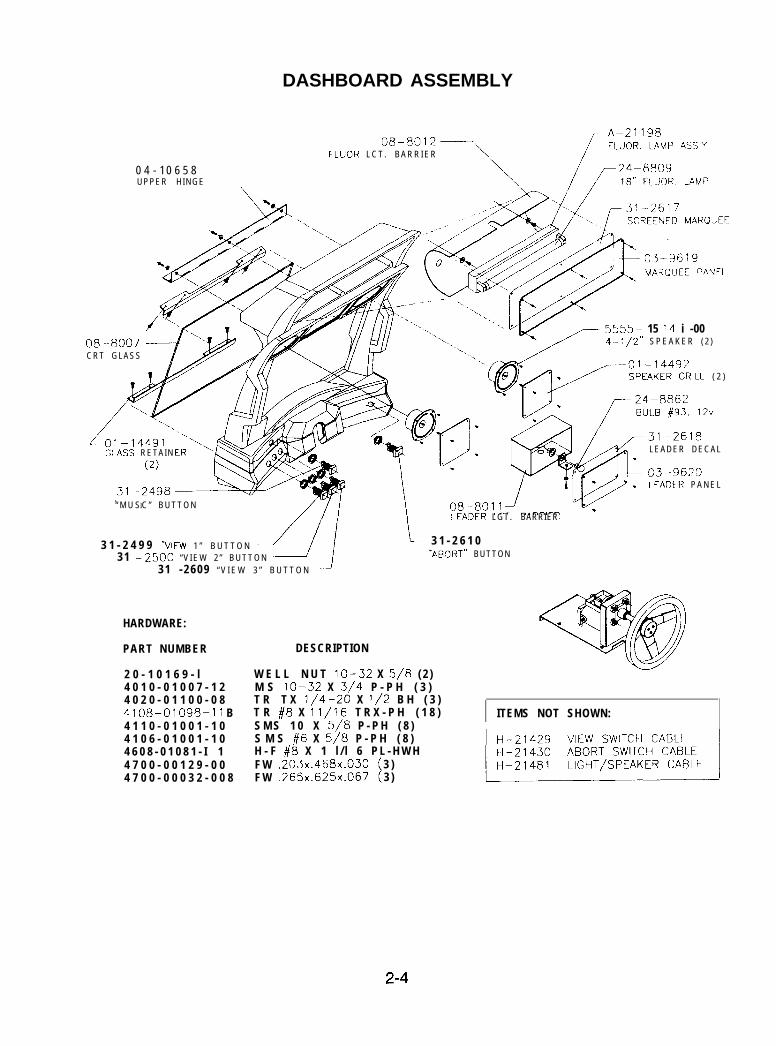
DASHBOARD ASSEMBLY
0 4 - 1 0 6 5 8UPPER HINGE
FLUOR L C T . B A R R I E R
r5555- 15 14 i -004-l/2” S P E A K E R ( 2 )
CRT GLASS
GiASS RETAIN
“ M U SIC ” B U T T O N[LEADER LGT . BARRIER
3 1 - 2 4 9 9 ‘VIEW 1 ” B U T T O N -/31 -2500 “ V I E W 2 ” B U T T O N
31 -2609 “ V I E W 3 ” B U T T O N
HARDWARE:
PART NUMBER DESCRIPTION
2 0 - 1 0 1 6 9 - l4 0 1 0 - 0 1 0 0 7 - 1 24 0 2 0 - 0 1 1 0 0 - 0 84108-01098- 11 B4 1 1 0 - 0 1 0 0 1 - 1 04 1 0 6 - 0 1 0 0 1 - 1 04 6 0 8 - 0 1 0 8 1 - I 14 7 0 0 - 0 0 1 2 9 - 0 04 7 0 0 - 0 0 0 3 2 - 0 0 8
W E L L N U T lo-32 X 5/8 ( 2 )M S lo-32 X 3/4 P - P H ( 3 )T R T X l/4-20 X l/2 B H ( 3 )T R #8 X 11/16 T R X - P H ( 1 8 )S M S 1 0 X 5/8 P - P H ( 8 )S M S #6 X 5/8 P - P H ( 8 )H - F #8 X 1 l / l 6 P L - H W HF W .203x.468x.030 3 )F W .265x.625x.067 3 )
( 2 )
LEADER DECAL
LEAaER P A N E L
i 3 1 - 2 6 1 0“ABOIIT” BUTTON
ITEMS NOT SHOWN:
2-4
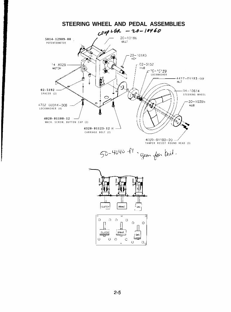
STEERING WHEEL AND PEDAL ASSEMBLIES
Gw Lm - z-8- lW605014-12909-00
P O T E N T I O M E T E R, / f 2;;;“‘“~
L v
I ,) ,~ I ii -
L O C K W A S H E R
4437-ni 183-w
02-5192S P A C E R ( 2 ) S T E E R I N G W H E E L
4702-00014-008L O C K W A S H E R ( 4 )
4020-01100-12M A C H . S C R E W , B U T T O N C A P ( 2 )
4320-01123-12C A R R I A G E B O L T ( 2 )
4020-OllOO-20JT A M P E R R E S I S T R O U N D H E A D ( 3 )
0
0 0
Al-CLUTCHw
0 0
0
0 0
2JBRAK(E
0 0n
0 0
La0 0,
2-5
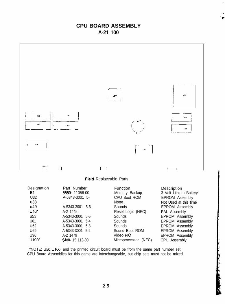
CPU BOARD ASSEMBLYA-21 100
‘_iu50 I“lCd
t a9 !i
rl n I I I
Field Replaceable Parts
Designation81U32u33u49u50*u53U61U62U69U96UlOO’
Part Number5680- 11056-00A-5343-3001 5-l___A-5343-3001 5-6A-2 1445A-5343-3001 5-5A-5343-3001 5-4A-5343-3001 5-3A-5343-3001 5-2A-2 14795400- 15 113-00
FunctionMemory BackupCPU Boot ROMNoneSoundsReset Logic (NEC)SoundsSoundsSoundsSound Boot ROMVideo PIGMicroprocessor (NEC)
Description3 Volt Lithium BatteryEPROM AssemblyNot Used at this timeEPROM AssemblyPAL AssemblyEPROM AssemblyEPROM AssemblyEPROM AssemblyEPROM AssemblyEPROM AssemblyCPU Assembly
*NOTE: U50, UlOO, and the printed circuit board must be from the same part number set.CPU Board Assemblies for this game are interchangeable, but chip sets must not be mixed.
2-6
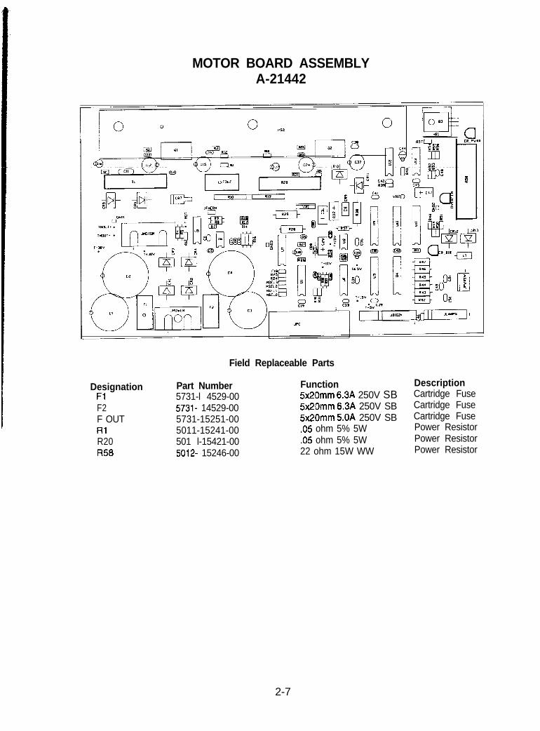
MOTOR BOARD ASSEMBLYA-21442
Field Replaceable Parts
Designation Part NumberFl 5731-l 4529-00F2 5731- 14529-00F OUT 5731-15251-00Rl 5011-15241-00R20 501 l-15421-00R58 5012- 15246-00
Function Description5x20mm 6.3A 250V SB Cartridge Fuse5x2Omm 6.3A 250V SB Cartridge Fuse5x20mm 5.OA 250V SB Cartridge Fuse.05 ohm 5% 5W Power Resistor.05 ohm 5% 5W Power Resistor22 ohm 15W WW Power Resistor
2-7
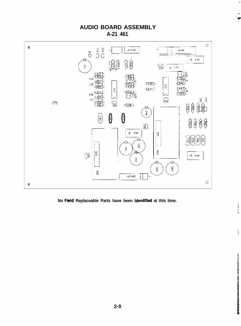
AUDIO BOARD ASSEMBLYA-21 461
0
Q
0
C l 6
0201
c_y c23
m
”05
No Field Replaceable Parts have been identlfled at thls time.
2-8
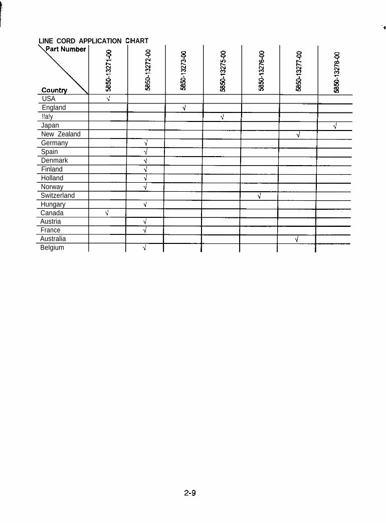
LINE CORD APPLICATION (
8;r:%
$
USA 4England!!a!yJapanNew ZealandGermanySpainDenmarkFinlandHollandNorwaySwitzerlandHungaryCanadaAustriaFranceAustraliaBelgium
HART
2-9
SAN FRANCISCO RUSH’”
S E C T I O NT H R E E
WIRING
3-1
jan
/ rt
_
3-2
UlOO
Ll0
LED INDICATOR STATUS CHART
FUNCTION
HARD DISKACTIVITY
COLORRED
DESIGNATION <LED 1
LED 2
LOCATIONCPU BOARDASSEMBLY
CPU BOARDASSEMBLY
CPU BOARDASSEMBLY
ON I LOCKED UP(Note 1)
BLINKING NORMALOPERATION
OFF NORMALOPERATION
ON PROCESSORRESET
BLINKING RESET LOOP(NOTE 2)
OFF NORMALOPERATION
ON PROCESSORRESET
BLINKING RESET LOOP(NOTE 3)
CPU RESETINDICA TOR
RED
YELLOWINDICATORLED 3
3-3
LED 4
LED 5
LED 6
LED 7
LED 8
LED 9
LED 10
LED 11
LED 12 1
CPU BOARDASSEMBLY
INDICATOR
CPU BOARDASSEMBLY
INDICATOR
CPU BOARD LINKASSEMBLY RECEIVE
CPU BOARDASSEMBLY
CPU BOARDASSEMBLY
CPU BOARDASSEMBLY
CPU BOARDASSEMBLY
CPU BOARDASSEMBLY
CPU BOARD 1ASSEMBLY
+12V POWERINDICATOR
-5V POWERINDICATOR
+5V POWERINDICATOR
LINK VERIFYPULSE
CPU LINKACTIVITY
LINKTRANSMIT
3-4
GREEN
GREEN
YELLOW
RED
RED
RED
GREEN
RED
RED
I OFF NO BOOT ROM(NOTE 4)
ON READING ROMINSTRUCTIONS
BLINKING NORMALOPERATION
OFF NO I/O FUNCTIONSPRESENT
ON NORMAL~~ OPERATLON~ ~
BLINKING I/O ASIC FAULT(NOTE 5)
OFF NOT IN USE(NO GAME LINK)
ON RECEIVING DATA(NOTE 6)
BLINKING NORMALOPERATION
OFF NO POWER
ON
BLINKING
OFF
NORMALOPERATION
POWER FAULT(Note 7)
NO POWER
ON
BLINKING
OFF
NORMALOPERATION
POWER FAULT(Note 8)
NO POWER
ON
BLINKING
OFF
ON
BLINKING
OFF
ON
BLINKING
OFF
ON
NORMALOPERATION
POWER FAULT(Note 9)
NOT IN USE(NO GAME LINK)
NORMALOPERATION
LINK FAULT (Note5)
NOT IN USE(NO GAME LINK)
CPU LINK ACTIVE(LINKED GAMES)
NORMALOPERATIONNOT IN USE
(NO GAME LINK)SENDING DATA
( N o t e 7 )
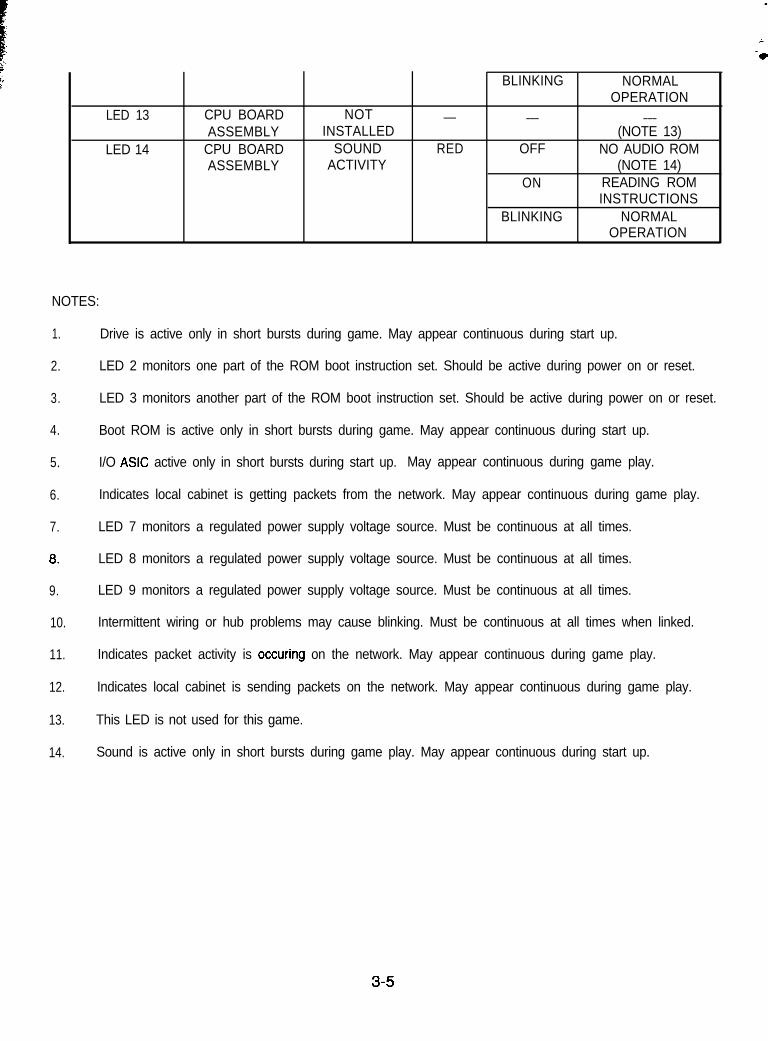
LED 13
LED 14
CPU BOARD NOTASSEMBLY INSTALLED
CPU BOARD SOUNDASSEMBLY ACTIVITY
___
RED
BLINKING
___
OFF
ON
BLINKING
NORMALOPERATION
___(NOTE 13)
NO AUDIO ROM(NOTE 14)
READING ROMINSTRUCTIONS
NORMALOPERATION
NOTES:
1.
2.
3.
4.
5.
6.
7.
0.
9.
10.
11.
12.
13.
14.
Drive is active only in short bursts during game. May appear continuous during start up.
LED 2 monitors one part of the ROM boot instruction set. Should be active during power on or reset.
LED 3 monitors another part of the ROM boot instruction set. Should be active during power on or reset.
Boot ROM is active only in short bursts during game. May appear continuous during start up.
I/O ASIC active only in short bursts during start up. May appear continuous during game play.
Indicates local cabinet is getting packets from the network. May appear continuous during game play.
LED 7 monitors a regulated power supply voltage source. Must be continuous at all times.
LED 8 monitors a regulated power supply voltage source. Must be continuous at all times.
LED 9 monitors a regulated power supply voltage source. Must be continuous at all times.
Intermittent wiring or hub problems may cause blinking. Must be continuous at all times when linked.
Indicates packet activity is occuring on the network. May appear continuous during game play.
Indicates local cabinet is sending packets on the network. May appear continuous during game play.
This LED is not used for this game.
Sound is active only in short bursts during game play. May appear continuous during start up.
3-5
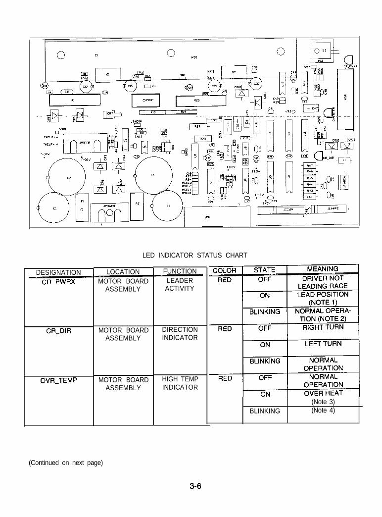
LED INDICATOR STATUS CHART
DESIGNATIONCR_PWRX
CR-DIR
OVR_TEMP
LOCATIONMOTOR BOARD
ASSEMBLY
MOTOR BOARD DIRECTIONASSEMBLY INDICATOR
MOTOR BOARDASSEMBLY
FUNCTIONLEADERACTIVITY
HIGH TEMPINDICATOR
BLINKING(Note 3)(Note 4)
(Continued on next page)
3-6
SAN FRANCISCO RUSH’”
S E C T I O NF O U R
TROUBLESHOOTINGThis game uses complex electronic components that are very SENSITIVE to static electricity.The following precautions must be observed and followed prior to handllng any of the gameelectronics.
1. Ensure that the AX. power to the game is turned OFF prior to servicing the electronics.2. Discharge any static electricity build up in your body by touching the safety ground stud
of the power supply chassis. This is to be done BEFORE touching or handling theelectronic assemblies.
3. Store the electronic assemblies in an anti-static area. Anti-static bags are to be used tostore or transport the game CPU Board Assembly.
4. DO NOT remove or connect any electronic assemblies when the cabinet power Is ON.Doing so will damage the electronic assemblles and void the warranty.
5. Always replace ground wires, shields, safety covers, etc. when maintenance or service Iscompleted.
4-1
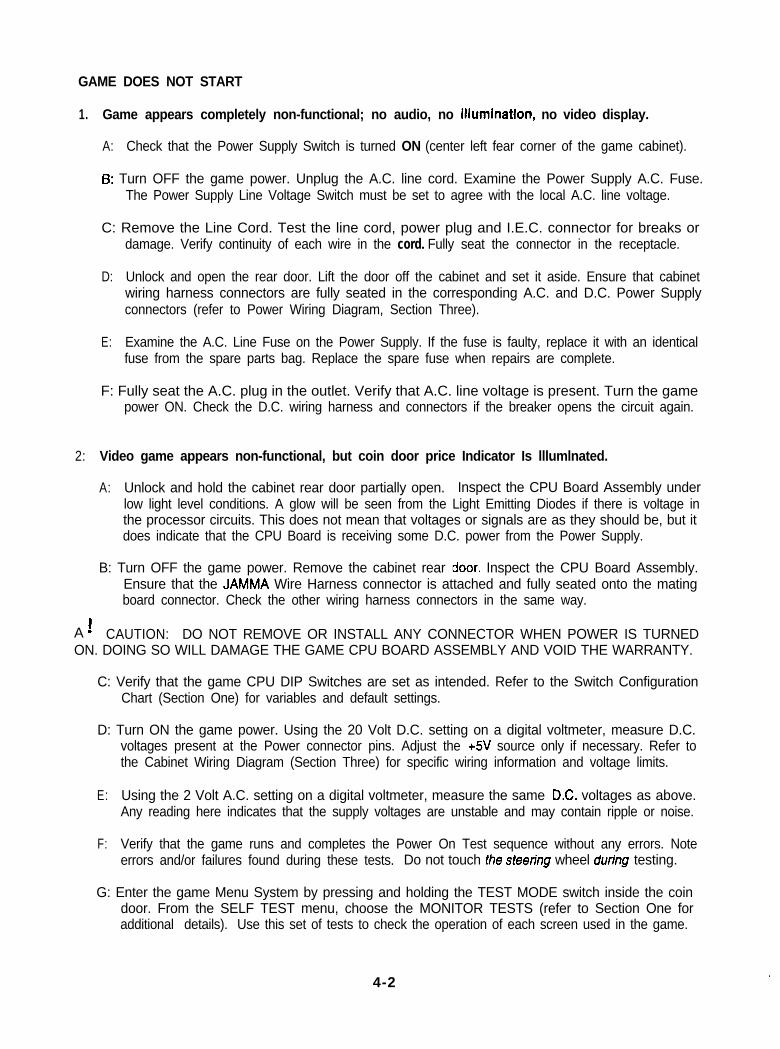
GAME DOES NOT START
1. Game appears completely non-functional; no audio, no illumination, no video display.
A: Check that the Power Supply Switch is turned ON (center left fear corner of the game cabinet).
6: Turn OFF the game power. Unplug the A.C. line cord. Examine the Power Supply A.C. Fuse.The Power Supply Line Voltage Switch must be set to agree with the local A.C. line voltage.
C: Remove the Line Cord. Test the line cord, power plug and I.E.C. connector for breaks ordamage. Verify continuity of each wire in the cord. Fully seat the connector in the receptacle.
D: Unlock and open the rear door. Lift the door off the cabinet and set it aside. Ensure that cabinetwiring harness connectors are fully seated in the corresponding A.C. and D.C. Power Supplyconnectors (refer to Power Wiring Diagram, Section Three).
E: Examine the A.C. Line Fuse on the Power Supply. If the fuse is faulty, replace it with an identicalfuse from the spare parts bag. Replace the spare fuse when repairs are complete.
F: Fully seat the A.C. plug in the outlet. Verify that A.C. line voltage is present. Turn the gamepower ON. Check the D.C. wiring harness and connectors if the breaker opens the circuit again.
2: Video game appears non-functional, but coin door price Indicator Is lllumlnated.
A: Unlock and hold the cabinet rear door partially open. Inspect the CPU Board Assembly underlow light level conditions. A glow will be seen from the Light Emitting Diodes if there is voltage inthe processor circuits. This does not mean that voltages or signals are as they should be, but itdoes indicate that the CPU Board is receiving some D.C. power from the Power Supply.
B: Turn OFF the game power. Remove the cabinet rear Idoor. Inspect the CPU Board Assembly.Ensure that the JAMMA Wire Harness connector is attached and fully seated onto the matingboard connector. Check the other wiring harness connectors in the same way.
A ! CAUTION: DO NOT REMOVE OR INSTALL ANY CONNECTOR WHEN POWER IS TURNEDON. DOING SO WILL DAMAGE THE GAME CPU BOARD ASSEMBLY AND VOID THE WARRANTY.
C: Verify that the game CPU DIP Switches are set as intended. Refer to the Switch ConfigurationChart (Section One) for variables and default settings.
D: Turn ON the game power. Using the 20 Volt D.C. setting on a digital voltmeter, measure D.C.voltages present at the Power connector pins. Adjust the +5V source only if necessary. Refer tothe Cabinet Wiring Diagram (Section Three) for specific wiring information and voltage limits.
E: Using the 2 Volt A.C. setting on a digital voltmeter, measure the same DC. voltages as above.Any reading here indicates that the supply voltages are unstable and may contain ripple or noise.
F: Verify that the game runs and completes the Power On Test sequence without any errors. Noteerrors and/or failures found during these tests. Do not touch the sfeedng wheel during testing.
G: Enter the game Menu System by pressing and holding the TEST MODE switch inside the coindoor. From the SELF TEST menu, choose the MONITOR TESTS (refer to Section One foradditional details). Use this set of tests to check the operation of each screen used in the game.
4-2
GAME CAN NOT BE PLAYED
1. Game will not accept currency or tokens and cannot be started. Audio and video are present.
A:
B:
c:
D:
E:
Unlock and open the cash door. Empty the cash box. Inspect the revenue for any counterfeitcurrency. Check the vault and remove any items that block the path from the mechanism.
Unlock and open the coin door. Check each mechanism by hand to ensure proper mounting.Remove the mechanism and clear the currency path. Reinstall the mechanism and latch it.
Verify that themechanism is ievei when the doors are ctosed. ~Repair or ~~~i~CS~tR~-GCM 61~0~ it
it is bent or damaged. Adjust the cabinet leg levelers if necessary to keep mechanisms vertical.
Enter the game Menu System by pressing and holding the TEST MODE switch inside the coindoor. From the SELF TEST menu, choose COIN OPTIONS (refer to Section One for additionaldetails). Use these tests to confirm the pricing and setup of each mechanism used in the game.
Enter the game Menu System by pressing and holding the TEST MODE switch inside the coindoor. From the SELF TEST menu, choose the CONTROL TESTS (refer to Section One foradditional details). Use this set of tests to check the operation of each coin or bill mechanism.
2. Game accepts currency or tokens, but does not start. Audio and video are present.
A:
B:
c:
D:
E:
F:
Unlock and open the coin door. Check each mechanism by hand to ensure proper mounting.Verify that each of the release latches is in the closed and locked position. Test known good andbad coins to see if the mechanism accepts and rejects the currency correctly.
Ensure that no loose parts or wires are caught in the hinges, latches, or switch contacts.
Inspect to see if the external coin door indicators (pricing, flashing arrows, etc.) are illuminated.Check connectors and cables for wiring continuity from CPU Board to the coin mechanisms.
Enter the game Menu System by pressing and holding the TEST MODE switch inside the coindoor. From the SELF TEST menu, choose COIN OPTIONS (refer to Section One for additionaldetails). Use these tests to confirm the pricing and setup of ezch mechanism used in the game.
Check for continuity in each of the suspect switch connections ( Common to Normally Open orCommon to Normally Closed). Replace faulty switches (bent levers, broken actuators, etc.).
Verify that each coin mechanism is operating properly by placing it in a known good unit.
3. Game functions correctly by itself, but does not recognize other players In linking operation.
A: Note and record any error messages that occur during self-test. Open the coin door. Press andhold the TEST MODE switch to enter the menu system. From the SELF TESTS menu, chooseNETWORK TESTS. These tests will verify some of the communication functions in this game.
8: Ensure that no loose parts or wires are caught in the hinges, doors, or under the cabinet.
C: Unlock and open the rear door. Verify that the linking cable is connected to the CPU Board.Check connectors and cables for wiring continuity from CPU Board to the other games.
4-3
PLAYER CONTROL PROBLEMS
1. Player controls are lntermittant or completely non-functional. Game starts normally.
A: Turn off power for one minute and turn the game on again. The automatic game POWER ONTESTS routine will check system electronics and player controls. Upon completion, the screenwill report any errors. Do not touch the steering wheel or the pedals during this calibration test.
6: Unlock and open the coin door. Enter the game Menu System by pressing and holding the TESTMODE switch inside the coin door. From the SELF TEST menu, choose the CONTROLS TEST(refer to Section One for additional details). Use these tests to confirm the operation of eachswitch and light used in the game.
C: Check that the cabinet wiring is correct for this game. Ensure that the controls are properlyconnected to the control input wires from the JAMMA connector. Refer to the Cabinet WiringDiagram (Section Three) for specific wiring information.
D: Ensure that no loose parts or wires are caught in the hinges, latches, or switch contacts. Checkcontinuity in each of the switch connections (Common to Normally Open or Common to NormallyClosed). Verify that the control is operating properly by placing in a known good unit.
2: Steering wheel Is partly functlonal, but video Is present and game appears to start normally.
A: Turn off power for one minute and turn the game on again. The automatic game POWER ONTESTS routine will test system electronics and player controls. Upon completion, the screen willreport any errors. Do not touch the steering wheel or the pedals during this calibration routine.
B: Unlock and hold the cabinet rear door partially open. Inspect the Motor Board Assembly underlow light level conditions. A glow will be seen from the Light Emitting Diodes if there is voltage inthe motor driver circuits. This does not mean that voltages or signals are as they should be, butit does indicate that the Motor Board is receiving some A.C. power from the transformer.
C: Turn OFF the game power. Adjust the seat to its maximum rear position. Open the dashboard.Support the steering wheel and remove the outer mounting screws. Remove the support andgently lower the wheel mechanism to the floor. Inspect for faulty belts, bearings, couplings, etc.
A ! WARNING: Motor Driver Board heatsink, power resistors, and other components may bevery HOT. The D.C. Motor In the Steering Wheel Assembly may also have become HOT.
D: Examine the three fuses on the Motor Driver Board. If any fuse is faulty, replace it with anidentical fuse from the spare parts bag. Replace the spare fuse when repairs are complete.
E: With the game power ON, check the air flow from each of the fans at the rear of the cabinet.
F: Using a digital voltmeter, verify that D.C. voltage present between the heatsink and ground isexactly half of the full supply voltage. Check the +15V, -15V, +lOV and +5V sources. Refer tothe Cabinet Wiring Diagram (Section Three) for specific wiring information and voltage limits.
G: Using the 2 Volt A.C. setting on a digital voltmeter, measure the same D.C. voltages as above.Any reading here indicates that the supply voltages are unstable and may contain ripple or noise.
H: Verify proper operation of game Motor Board Assembly by placing it in a known good game.
4-4
AUDIO PROBLEMS
1: Audio is non-functional, but video is present and game appears to operate normally.
A: Unlock and open the coin door. Enter the game Menu System by pressing and holding the TESTMODE switch inside the coin door. From the SELF TEST menu, choose ADJUST VOLUME(refer to Section One for additional details). Verify that the attract and game volume levels havenot been set at zero. Change the levels if necessary to make the game very loud.
B: Fo!!ow !he on-screen instruc!ions to return to the first menu. From the SELF TEST menu,choose SOUND TESTS. Use these tests to confirm the operation of each speaker in the cabinet.
C: Turn OFF the game power. Inspect each speaker and its wiring harness. Ensure that no looseparts or wires are caught in speaker cones, terminals, mounting screws, or stuck to the magnets.Do not use excess force when removing or tightening mounting screws threaded into plastic.
D: Verify correct cabinet wiring for this game. Ensure that the speakers are properly connected tothe audio output wires from the speaker connector. Verify speaker continuity. Refer to theCabinet Wiring Diagram (Section Three) for specific wiring information.
E: Turn ON the game power. Using the 20 Volt D.C. setting on a digital voltmeter, measure D.C.voltages present at the Power connectors. Verify the +12V source at the Audio board. Refer tothe Cabinet Wiring Diagram (Section Three) for specific wiring information and voltage limits.
F: Using the 2 Volt A.C. setting on a digital voltmeter, measure the same D.C. voltages as above.Any reading here indicates that the supply voltages are unstable and may contain ripple or noise.
G: Verify proper operation of suspect Audio and CPU Boards by placing in a known good game.
2: The audio is distorted, muffled or missing frequencies. A constant low hum may be present.
A: Unlock and open the coin door. Enter the game Menu System by pressing and holding the TESTMODE switch inside the coin door. From the SELF TEST menu, choose SOUND TESTS.These tests will verify some of the functions of the audio circuits in this game.
B: Turn OFF the game power. Remove the grills and check the speakers. This game uses fourspeakers and one subwoofer. Ensure that each small speaker is FULL RANGE (100 to 10,000Hz response) and rated for at least 15 WATTS. The large speaker must rate at least 25 WATTS.
C: Check that the speaker wiring is not reversed at one of the speakers. Weak low frequencies anda thin or hollow sound quality is a symptom of incorrectly phased speakers. This condition willnot be detected by the SOUND TESTS, but it will be audible with the ADJUST VOLUME music.
D: Check that the cabinet wiring is correct for this game. Verify that the cabinet wiring providesseparate wires (not a common return) for each speaker. Ensure that all cabinet ground wires areconnected. Refer to the Cabinet Wiring Diagram (Section Three) for specific wiring information.
E: Using the 2 Volt A.C. setting on a digital voltmeter, measure voltages at the speaker terminals.Any reading here indicates that the supply voltages are unstable and may contain ripple or noise.
F: Verify that the speaker is operating properly by placing in a known good unit.
4-5
VIDEO PROBLEMS
1. Monitor appears non-functional, but audio is present and controls operate as expected.
A:
B:
c:
D:
E:
F:
Unlock and open the rear door. Verify that A.C. Power is connected to the Video Monitor.Inspect the neck of the CRT under low light level conditions. A glow will be seen near the CRTbase if there is voltage in the filament circuits. This does not mean that other voltages or signalsare as they should be, but it does indicate that some of the monitor circuits are receiving power.
Turn OFF the game power. Verify that the Video Signal and the Remote Adjustment Boardconnectors are fuul~y seated on the Video Monitor Board Assembly. Check the othe: monitorconnectors in the same way.
Examine the A.C. line fuse on the Video Monitor Board Assembly. If the fuse is faulty, replace itwith an identical fuse of the proper voltage and current rating.
Ensure that no loose parts or wires are caught on the chassis or the mounting brackets.
Check that the brightness (intensity) and contrast have not been set to their minimum levels.
Verify that the Video Monitor is operating correctly by placing it in a known good unit.
2: The Power On Tests will run, but the game does not appear. No audio is present.
A:
B:
Note and record any error messages that occur during Power On Test. Open the coin door.Press and hold the TEST MODE switch to enter the menu system. From the SELF TESTSmenu, choose DISK TESTS. These tests will verify some of the game Hard Disk Drive functions.
Turn OFF the game power. Unlock and remove the rear door. Inspect the CPU Board Assembly.Ensure that the Hard Disk Drive Assembly ribbon cable connector is fully seated into the matingshrouded connector on th CPU Board. Verify that ail hard drive mounting screws are installed.
CAUTION: DO NOT REMOVE OR INSTALL ANY CONNECTOR WHEN POWER IS TURNED ON.THIS WILL DAMAGE THE CPU BOARD OR HARD DISK DRIVE AND VOID THE WARRANTY.
c:
D:
E:
F:
G:
H:
Check that the Hard Disk Drive Assembly is the correct part for this game. Each Hard Disk Driveis labeled with the assembly number and the software version. Refer to Parts (Section Two).
Verify that the ROM instruction set is correct for this game. There is more than one ROM in agame set. Each ROM circuit is labeled with the assembly number and the software version.
Verify that the CPU Board Assembly is correct for this game. Each CPU Board is marked withthe manufacturer name, assembly number and the hardware version.
Turn ON the game power. Using the 20 Volt D.C. setting on a digital voltmeter, measure D.C.voltages present at the Power connector pins. Verify the +5V source if it is adjustable. Refer tothe Cabinet Wiring Diagram (Section Three) for specific wiring information and voltage limits.
Using the 2 Volt A.C. setting on a digital voltmeter, measure the same D.C. voltages as above.Any reading indicates that the supply voltages are unstable and may contain ripple or noise.
Compare CPU Board Light Emitting Diode states with the CPU Indicator Chart (Section Three).
4-6
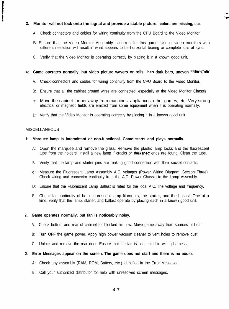
3. Monitor will not lock onto the signal and provide a stable picture, colors are missing, etc.
A: Check connectors and cables for wiring continuity from the CPU Board to the Video Monitor.
B: Ensure that the Video Monitor Assembly is correct for this game. Use of video monitors withdifferent resolution will result in what appears to be horizontal tearing or complete loss of sync.
C: Verify that the Video Monitor is operating correctly by placing it in a known good unit.
4: Game operates normally, but video picture wavers or roils, ~has dark bars, uneven coTorS;etc:
A:
B:
c:
D:
Check connectors and cables for wiring continuity from the CPU Board to the Video Monitor.
Ensure that all the cabinet ground wires are connected, especially at the Video Monitor Chassis.
Move the cabinet farther away from machines, appliances, other games, etc. Very strongelectrical or magnetic fields are emitted from some equipment when it is operating normally.
Verify that the Video Monitor is operating correctly by placing it in a known good unit.
MISCELLANEOUS
1: Marquee lamp is intermittant or non-functional. Game starts and plays normally.
A:
B:
c:
D:
E:
Open the marquee and remove the glass. Remove the plastic lamp locks and the fluorescenttube from the holders. Install a new lamp if cracks or darkened ends are found. Clean the tube.
Verify that the lamp and starter pins are making good connection with their socket contacts.
Measure the Fluorescent Lamp Assembly A.C. voltages (Power Wiring Diagram, Section Three).Check wiring and connector continuity from the A.C. Power Chassis to the Lamp Assembly.
Ensure that the Fluorescent Lamp Ballast is rated for the local A.C. line voltage and frequency.
Check for continuity of both fluorescent lamp filaments, the starter, and the ballast. One at atime, verify that the lamp, starter, and ballast operate by placing each in a known good unit.
2. Game operates normally, but fan is noticeably noisy.
A: Check bottom and rear of cabinet for blocked air flow. Move game away from sources of heat.
B: Turn OFF the game power. Apply high power vacuum cleaner to vent holes to remove dust.
C: Unlock and remove the rear door. Ensure that the fan is connected to wiring harness.
3. Error Messages appear on the screen. The game does not start and there is no audio.
A: Check any assembly (RAM, ROM, Battery, etc.) identified in the Error Messasge.
B: Call your authorized distributor for help with unresolved screen messages.
4-7
ATARIGA~IES
DECEMBER 199616-10330
SAN FRANCISCO RUSH TM
HUB LINK KITFor Linking up to Eight Games Together
INSTALLATION
l-1
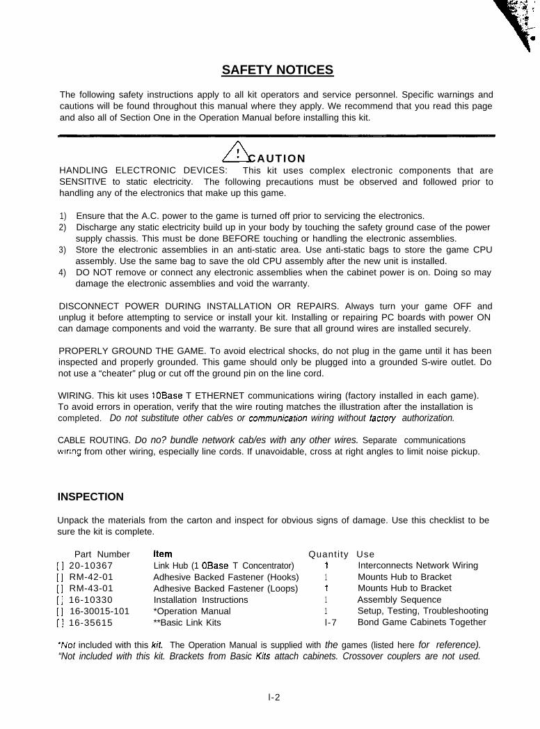
SAFETY NOTICES
The following safety instructions apply to all kit operators and service personnel. Specific warnings andcautions will be found throughout this manual where they apply. We recommend that you read this pageand also all of Section One in the Operation Manual before installing this kit.
A! CAUTIONHANDLING ELECTRONIC DEVICES: This kit uses complex electronic components that areSENSITIVE to static electricity. The following precautions must be observed and followed prior tohandling any of the electronics that make up this game.
1) Ensure that the A.C. power to the game is turned off prior to servicing the electronics.2) Discharge any static electricity build up in your body by touching the safety ground case of the power
supply chassis. This must be done BEFORE touching or handling the electronic assemblies.3) Store the electronic assemblies in an anti-static area. Use anti-static bags to store the game CPU
assembly. Use the same bag to save the old CPU assembly after the new unit is installed.4) DO NOT remove or connect any electronic assemblies when the cabinet power is on. Doing so may
damage the electronic assemblies and void the warranty.
DISCONNECT POWER DURING INSTALLATION OR REPAIRS. Always turn your game OFF andunplug it before attempting to service or install your kit. Installing or repairing PC boards with power ONcan damage components and void the warranty. Be sure that all ground wires are installed securely.
PROPERLY GROUND THE GAME. To avoid electrical shocks, do not plug in the game until it has beeninspected and properly grounded. This game should only be plugged into a grounded S-wire outlet. Donot use a “cheater” plug or cut off the ground pin on the line cord.
WIRING. This kit uses 10Base T ETHERNET communications wiring (factory installed in each game).To avoid errors in operation, verify that the wire routing matches the illustration after the installation iscompleted. Do not substitute other cab/es or communicafion wiring without facfory authorization.
CABLE ROUTING. Do no? bundle network cab/es with any other wires. Separate communicationswrnng from other wiring, especially line cords. If unavoidable, cross at right angles to limit noise pickup.
INSPECTION
Unpack the materials from the carton and inspect for obvious signs of damage. Use this checklist to besure the kit is complete.
Part Number Item Quanti ty Use[ ] 20-10367 Link Hub (1 OBase T Concentrator) 1 Interconnects Network Wiring[ ] RM-42-01 Adhesive Backed Fastener (Hooks) 1 Mounts Hub to Bracket[ ] RM-43-01 Adhesive Backed Fastener (Loops) 1 Mounts Hub to Bracket[ ] 16-10330 Installation Instructions 1 Assembly Sequence[ ] 16-30015-101 *Operation Manual 1 Setup, Testing, Troubleshooting[ ] 16-35615 **Basic Link Kits l-7 Bond Game Cabinets Together
‘Not included with this kit. The Operation Manual is supplied with the games (listed here for reference).“Not included with this kit. Brackets from Basic Kifs attach cabinets. Crossover couplers are not used.
l -2
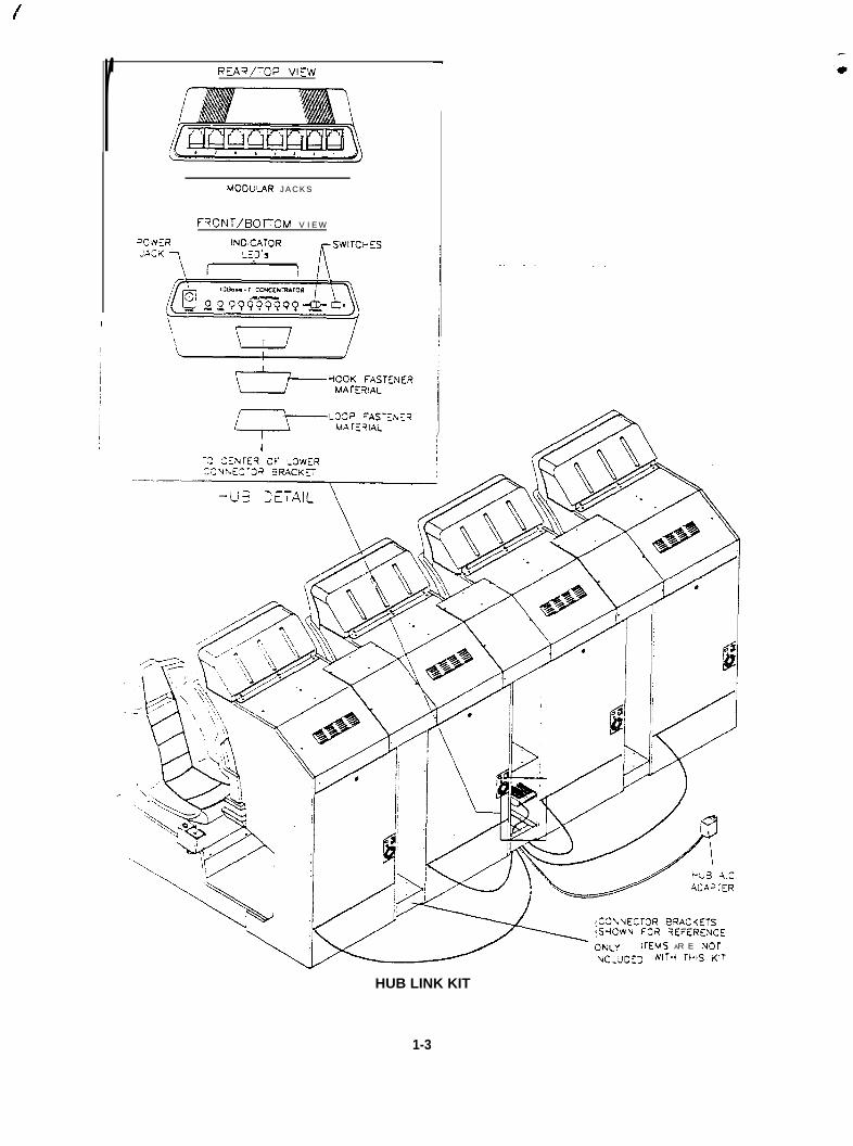
rI
REA?,‘-CP VIE’&
MOOG’_AR J A C K S
F~~N~/I~o~oM V I E W
=OiVN_R INO<CATOR
C3’.UECTOR @=?AC<ETSSrICWU F32 SEFERENCE
lK3.G AR E uOT‘NIT-1 U-IS K’T
HUB LINK KIT
1-3
PRODUCT SPECIFICATIONS
Operating RequirementsLOCafiOn Electrical PowerDomestic 120VAC @ 60Hz 0.1 Amps
Temperature68°F to 100°F(20°C to 38°C)
HumidityNot to exceed 70% relative
NETWORK CONSIDERATIONS
1. Cables for the network are supplied with the games. The factory installed cables are long enough toreach to the Hub in any configuration which uses the connector brackets to link up to eight cabinets.
2. The Hub may be located remotely if monitoring of network activity is desired. Longer cables (up to328 ft. or 100 meters) may be used provided they are Category 3 (or higher) 100 ohm unshieldedtwisted pair communications grade wiring. Do not use standard telephone vpe cables.
3. Protect exposed wiring from player foot traffic, cleaning crews, service personnel, etc. Use approvedconduit or wire channels to support cables. These modular connectors do not have strain relief.
4. Keep cables away from sources of heat, moisture, high energy (neon signs, fluorescent fixtures, two-way radios, cordless telephones, power circuits, public address speaker wiring, etc.).
5. The universal RJ-45 modular plugs are not keyed, numbered, or coded in any way. Clearly mark allgame network connections so that they cannot be confused with computer or telephone circuits.
CABINET MODIFICATIONS
1. Verify the operation of the existing games before making any changes to the cabinet. Unlock thecoin doors of all cabinets. Press and hold the coin door TEST MODE button to enter the menusystem, then compare car colors. Go to GAME OPTIONS and make each game’s car color different.
2. Switch off power to the games. Disconnect the line cords from the A.C. power. Raise the leglevelers and position the cabinets side by side approximately one foot (30 cm) apart. Remove threescrews at the bottom and three screws at the top of each of the facing cabinet sides.
3. Locate the Lower Connector Brackets and install them as directed in the Basic Link Kit instructions.
4 Locate the Upper Connector Brackets and install them as directed in the Basic Link Kit instructions.
5. Repeat these steps for the other cabinets until all games are fastened together. Do not attach morethan eight games in one group (only eight cars can compete on one track during a game).
l -4

WIRING MODIFICATIONS
1.
2.
3.
4.
5.
6.
7.
8.
9.
10
Place the Hub near one of the Lower Connector Brackets at the center of the linked cabinet array.NOTE: Arrays with three, five, or seven cabinets will have two brackets near the center. Select one.
The Crossover Couplers supplied with the Basic Link Kits are not required when a Hub is installed.Store the couplers inside of one of the empty Lower Connector Brackets if desired.
Unlock and remove the cabinet rear doors. The linking cable is coiled up inside the cabinet with oneend attached to a jack on the CPU board. Cut the cable tie and locate the free end. Uncoil just---*a-h r-k’- +A ra-*h tha Ullh I nucw rnnncrrtnr &a~@eIl”“ylI La”,= I” I=abII III= I I ” ” L”..CI d”llllr”.“I t+n mrnil a n d ptip the remajq&r of the( L I”, . . Y”“.. I. ._ _.._ . ..e ._..._.. __.cable. Repeat this procedure for the other cabinets. Do not reinstall cabinet rear doors at this time.
Route the free ends of the cabinet cables under the near end of the Lower Connector Bracket. Bringthem up through the rear hole in the bottom of the bracket and plug them into any of the jacks on theHub rear panel. Place the Hub on the bottom of the connector bracket.
Route the free end of the Hub A.C. Adapter under the near end of the Lower Connector Bracket.Bring it up through the front hole in the bottom of the bracket and plug it into the 9 V.A.C. jack on theHub front panel. The Hub must now be connected to all of the cables and resting between the holes.
Set the Hub front panel switches to the LNK (link) and X (crossover) positions.
Peel the backing off of the hook fastener material and place it in the center of the Hub case bottom.Press firmly to set the adhesive. Attach the loop fastener material to the center of the bracket in thesame way. Orient the hub directly over the bracket and press down to join the fasteners together.
Retract any excess cable back into the coils in the cabinet so that the cables do not touch the floor.This keeps the cables away from the cabinet wheels during relocation.
Raise the leg levelers and roll cabinets to their intended destination. Connect the A.C. Adapter andilne cords to A.C. power and turn on each of the cabinets. Examine the screens of all cabinets.
The games will start up and begin the Power On Tests. If no errors are found, each game will enterI& ‘attract” mode automatically. Refer to Section Four of the Operation Manual if problems occur.
Do not connect or disconnect any cable to the CPU board or coupler with the power turned on.Doing so while the power is turned on may damage the game and void your warranty.
1 1. Unlock the coin doors of all cabinets. Press and hold the coin door TEST MODE button to enter themenu system. Use the MUSIC and VIEW buttons to select NETWORK TESTS, then press ABORTto make the tests active. Refer to Section One of the Operation Manual for assistance.
12. When all test results are satisfactory. return to the the SELF TEST menu screens and choose EXITTO GAME. Start up linked games and ensure that each cabinet’s player controls affect the same caron all screens. CPU and Hub LEDS will indicate communication activity between the two games.
NOTE: The Hub COL Indicator flashes periodically during use when two or more Informationpackets arrive simultaneously. These collisions are normal and do not affect game operation.
13. Close and lock the coin doors. Reinstall and lock the rear cabinet doors. Place the covers on theLower Connector Brackets and align the mounting holes. Insert screws through washers into coverholes and tighten. Lower all leg levelers until wheels lift off of the floor, then level the cabinets.
l -5
.
DECEMBL;R I99616-10326
ATARIGAMES
SAN FRANCISCO RUSH TM
BASIC LINK KITFor Linking Two 30015 Games Together
INSTALLATION
l - l
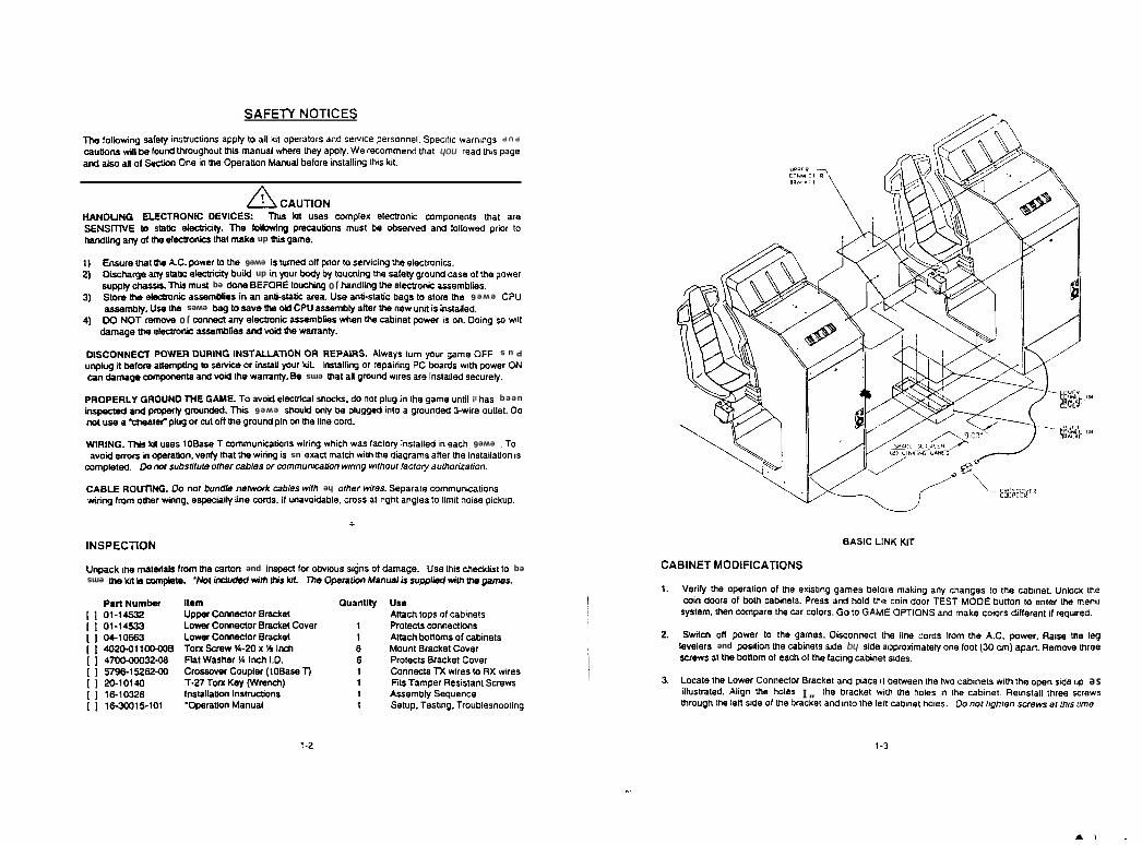
. \.
._
E-L2-l
‘eu~ WJ Je sMe~3S UaJU6,J JoU 00‘salou JeuW3 WI 841 Olul pue ,eyoe,q a~ ,o epfs me, ew u6no~U1SMBJoS m)UJ IJelsulek, ‘leulqso WI WI seloU eL” L”!M JeWeJCJ el,J “I SW,o,, eL,J U6!(V ‘peJe,JS”,,!se dn ep!s uado euJ uw sieulqes 0~1 eu~ uaermaq ,I eoeld pus ,ey,e,g ,ouauuo3 ,emo, eU, e,rro,
‘SJPIS tiau1qe3 blJ!XJ eq, ,o lpea ,o wouoq eLQ \e EM8JoseWI eAowek3 ‘uede two OC) lo01 euo 4elewpoJdde ep!s hq ep!s sieu!qeo et4 uo!l!sod pue oele~el6el cut es!etl ‘Jemod ‘3’~ erll wo4 sp~oo eu!~ a14 rmuoos!a xewe6 841 0J mod ~0 qaJ!rn~
wJlnbel1! J=ww ~~0103 eww we stmlldo 3byv~ 01 09 3~0103 ~e3 841 emdwoo ue~ ‘weI&nuau 841 jeiue 01 uomq 300~ 1~31 JOOP u!o3 a41 PIOU put sseld ‘steufqeo ~0q ~0 SJOOP u!03WI xoolufl %u!qeo eui OI se6ueu3 hue 6un(m e.mJeq sewe6 6uRsve FIJI 10 uo!leJedo eg 4peA
SNOllV3lNlOW 13NIBV3
IIY UN11 3lSVB
bu!looUselqno>l ‘Su!lsal ‘dnreSeouenbeg kqwessv
SMBJ~S lueis!seH ledwe 9~se,!* xu 01 se,!* u s~oeuucg
Jan03 ley3eJg saoe~old~0~03 aeyowg wnow
sleu!qeo IO swouoq 43~~suo!13euuo3 t3oua8oJd
sleu!qeo ,o sdor uoeuv
eonhuiueno
lenuew uoueJedo.suonm4su~ uoneiieisui
WJ~JNJ hen x101 ~2-1
LOI5KJCJE-919ZE0191op101-02.
06-29ZSL36LsBO-ZcOOO-OOLt
B00-0011002opC9901-K)ECSPL-10ztx?l-LO
JeWnN Wd
xn~e6 ecR U~IM wfddns s! ,enue~ uogs~edo ecu‘M sg ~IW pepnpu! 8~.*emdwrr g t!~ w emseq 01 ~!~oaUo s!qi esn‘e6ewep 80 su@ snoyqo >oJ uadsu! pue uoue3 ecll wolj ~ueaew eln yoedun
NOlL33dSNI
t
.dnx>!d es!ou pwy 01 selbue 1U6u le ssom ‘elqop!ofieun 41 ‘sp>oo euy blqoedse ‘6ut4m ~eulo wolJ 6WJlmsuo!W!unwwoo elemdeg ‘se,j~ laylo he UJLM seJWJ yom)eu elpung ,ou 00 ‘DNlJJlOU 3lev3
‘UO!JI?~VOUJ~E hone) J”O~JH 60~1~ oogewnuum ~0 SSJC~~ muto eJnJJJsqns JW or3‘pelaldwwSI uo~e~~eisu! eql gene swwde!p 841 u!rn ~$JwJ nsxe us s! &P++ eq leql @ueA ‘uo!~wedo u! s)oue ROM01 r ewe6 U3e.s u! peiie$su! hopeJ seM Uo!Um 6uuy suogeo!unwwoo 1 esegg~ sesn 8p1 nul ‘DNIUIM
‘~103 euy eq~ uo u!d puno~6 et4 NO II-O JO 6nfd Jeleeuo. e esn 1~og ‘ielino eJ!m% pepunod e o&u! pe66nld eq &uo ~noqs ewe6 s!u 7~epuncu6 Apedcud We PeWdsulueeq seq I! t!aun etue6 ew u! 6nld IOU op ‘syooqs leo!4oefa ~ohe 01 -3~~3 3l.u aNnOt AltJ3dOkid
$emoes pallelsu! eje set, puno~d lie ~4 ems eg .kuouem er(l BOA pus sweuodwo~ e6ewe~ ue3NO JeMOd W!M spleoq 3d 6uyedeJ 10 6u!llmsul-@y moK ~~EWU! JO eoy~es o16uPdwene erolaq P 6n1dunPus 2.30 ewe6 Jnd W shemiv -sUIvd3tl t10 NOUVITV~SNI 9NILlna tfaMOd KEINN03SlCI
II!M OS 6yog ‘uo s! mood reu!qeJ eg ueqm seflqwesse quqe Aue $oeuua~ JO BK)W AON 0~3b‘pei~wsu! s! t!un wu eq~ Jeye hqwesse n,jD ~0 eyr eAes 016eq ewes eq~ esn Wwesse
nd3 ewe6 erll ~JOIS 01 s6eq agss-pue esn xene ogas-Rue M u! sewqwesse tyuoq3e(e WI WWSk‘se!lqwesss 3yoJDele em 6ugpueq JO Su&pnoj gt)og~ euop eq )snw nyl ‘s!sseW &idns
Jarnod e\n )o 85~ puno~d hejes er(l6uyono1 Aq Apoq Jnoh u! dn Pnnq @me CQQS Aus ehWWJ(2‘s3yo4oeia ew 6u!oyues 01 loud j~o perun~ s! ewe6 eu 01 mmod ‘3-v eq~ JW emsu3(1
‘ewe6 sg dn exew ieg sz+~o4oep ew #J he ~U!IP~R(01 jo!Jd pemoiio~ Pue p~uesqo eq isnw suqlnexud 6ulmqiq eta W+weie mw a %UJSN~Swe ~8 swuodum c+~oq~ale xeldww sesn w nu:s331~30 31~0~13313 wriatw4
NOLLllV’3 ;v
-try s!q~ Bu!tleisu! eJoleq @nw uo!Wedo ew u! au0 uwJS lo W cs@ Fa6ed s&n peal noh JW puewruoze, eM ,hdde hew e>eqh+ @nvew nu Inoq6noJw punoj eq IIW ~WI~WPUP s6u~em %JtmdS ‘iauuosmd axuas pus sjo!eJado 1~ Ife 01 hdde suo93n4su~ Keyes 6u~o11oJ eql
S33110N AL3zWS
4.
5.
6.
7.
Move the other cabinet in until its side touches the Lower Connector Bracket. Align the holes in thebracket with the holes in the cabinet. Reinstall three screws through the right side of the bracket andinto the right cabinet holes. Do no1 tighten screws at this lime.
Remove three screws at the top of each cabinet where the sides face the Lower Connector Bracket.
Locate the Upper Connector Bracket and place it over the facing sides of the cabinets. Align theholes in the bracket with the holes in the left cabinet. Reinstall three screws through the left side offhe bracket and into the left cabinet hofes. Do not tighten screws at Ihis lime.
Lower the leg levelers as required to align the holes in the bracket with the holes in the right cabinet.Reinstall three screws through the right side of the bracket and into the right cabinet holes. Tightenail screws in the Lower Connector Bracket, then tighten all screws in fhe Upper Conector Bracket.
WIRING MODIFICATIONS
1.
2.
3.
4.
5.
6.
Unlock and remove the cabinet rear doors. The linking cable is coiled up inside the cabinet with oneend attached to a jack on the CPU board. Cut the cable tie and locate the free end. Uncoil justenough cable to reach to the outer side of the other cabinet, then recoil and retie the remainder of thecable. Repeat this procedure for the other cabinet. Do nol reinstall cabinet rear doors at Ihis time.
Route the free end of the left cabinet cable under the the near end of Ihe Lower Connector Bracket.Bring it up through the rear hole in the bottom of the bracket and plug it Into either jack on theCrossover Coupler. Place the coupler on the bottom of the connector bracket.
Route the free end of the right cabinet cable under the near end of the Lower Connector Bracket.Bring it up through the front hole in the bottom of the bracket and plug it into the other jack on theCrossover Coupler. The coupler must now be connected to both cables and between the holes.
Retract any excess cable back into the coils in the cabinet so that the cables do not touch the floor.This keeps the cables away from the cabinet wheels during relocation.
Raise the leg levelers and roll the cabinets to their intended destination. Connect the line cords toA.C. power and turn on both cabinets. Examine the screens of both cabinets.
The games will start up and begin the Power On Tests. If no errors are found, each game will enterits ‘attract” mode automaticalty. Refer to Section Four of the Operation Manual if problems occur.
Do not connect or disconnect any cable to the CPU board or coupler with the power turned on.Doing so while the power Is turned on may damage the game and void your warranty.
7. Unlock the coin doors of both cabinets. Press and hold the coin door TEST MODE button to enterthe menu system. Use the MUSIC and VIEW buttons to select NETWORK TESTS, then pressABORT to make the tests active. Refer to Section One of the Operation Manual for assistance.
8. When all test results are satisfactory, return to the the SELF TEST menu screens and choose EXITTO GAME. Start up a linked game and ensure that each cabinet’s player controls affect the samecar on both screens. CPU board LEDS will indicate communication activity between the two games.
9. Close and lock the coin doors. Reinstall and lock the rear cabinet doors. Place the cover on theLower Connector Bracket and align the mounting holes. Insert screws through washers into coverholes and tighten. Lower ail leg levelers until wheels lift off of the floor, then level the cabinets.
l-4
ATARIGAMES
DECEMBER 199616-10327
SAN FRANCISCO RUSH’”
BANNER KITFor Advertising Games
NOTE: Minimum ceiling height of 89 Inches (2.26 Meters) is required for this kit.
INSTALLATION
l-l
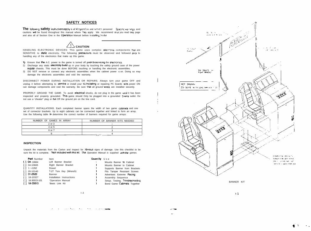
SAFETY NOTICES
The lollovmg safety instrucllons appiy lo all k11 opetalors and sewte personnel Spec111c wamngs andcautions wll be found throughout this manual where lhey apply We recommend lhal you read lhls pageand also all of Section One in the Operatlon Manual before lnslalllng lh!s kit
A! CAUTIONHANDLING ELECTRONIC DEVICES: This game uses complex electronic components that areSENSITIVE to stalic electricity. The following precaubons must be observed and followed prcot lohandling any of the electronics that make up this game.
1) Ensure that Ihe A.C. power to the game is turned off pnor to serwng the electronics.2) Discharge any static eleclriclty bulld up in your body by touching the safety ground case of the power
supply chassis. This must be done BEFORE touching or handling the electronic assemblies.3) DO NOT remove or connect any electronic assemblies when the cabinet power IS on. Doing so may
damage the electronic assemblies and void the warranty.
DISCONNECT POWER DURING INSTALLATION OR REPAIRS. Always turn your game OFF andunplug it before attempting to SeNiCe or install your k&t. InstallIng or repairing PC boards wth power ONcan damage components and void the warranty. Be sure that all ground wtes are installed securely.
PROPERLY GROUND THE GAME. To avoid electrICal shocks, do not plug in the game until it has beeninspected and property grounded. This game should Only be plugged into a grounded 3.wire outlet. Donot use a ‘cheater” plug or cul Off the ground pin on the line cord.
QUANTITY INSTALLATIONS. Each completed banner spans the width of two game cabmets and oneset of connector brackets. Up to eight cabinets can be connected together and linked to form an array.Use the following table lo determine the correct number of banners required for game arrays:
NUMBER OF GAMES IN ARRAY NUMBER OF BANNER KITS NEEDED2 or 3 14 or 5 26 or 7 3
6 4
INSPECTION
Unpack the materials from the Carton and inspect for obwous signs of damage. Use this checklist to besure the kit is complete. ‘Nof induded wlh fhis kt The Operation Manual is supplied mfh Ihe games.
I IPart Number Item Quantity U s e04- 10664 Left Banner Bracket 1 Mounts Banner lo Cabinet04-10665 Right Banner Bracket 1 Mounts Banner to Cabinet1 i-1262 Dowel 1 Supports Banner from Brackets20-10140 T-27 Torx Key (Wrench) 1 Fits Tamper Resistant Screws31-2620 Banner 1 Advertises Extreme Racmg16-10327 Installation Instructions 1 Assembly Sequence16-30015-101 ‘Operation Manual 1 Setup. Testing, Troubleshootmg16-35615 ‘Basic Link Kit 1 Bond Game Cabmets Together
l -2
> _. : _‘“,:. .__ -... __.____
BANNER KIT
l-3
-a
CABINET MODIFICATIONS
1. Verify the operation of the existing games before making any changes to the cabinet. Unlock thecoin doors of all cabinets. Press and hold the coin door TEST MODE button to enter the menusystem, then compare the car colors. Go to GAME OPTIONS and change the colors if necessary.
2. Switch off power to the games. Disconnect the line cords from the A.C. power. Raise the legi@i&iS ZKi ijOSiiiOfi ihe iXibiii&S Sicit? tiy Sidi? appioxiiiiaiei)i one foot(30 crti)apari. RemcWe threescrews at the bottom and three screws at the top of each of the facing cabinet sides.
3. Locate the Lower Connector Brackets and install them as directed in the Basic Link Kit instructions.
4. Locate the Upper Connector Brackets and install them as directed in the Basic Link Kit instructions.
5. Locate the Connector Bracket Covers.and install them as directed in the Basic Link Kit instructions.
6. Repeat these steps for the other cabinets until all games are fastened together. Do not attach morethan eight games in one group (only eight cars can compete on one track during a game).
BANNER ASSEMBLY
1.
2.
3.
4.
5.
6.
7.
6.
9.
Flatten the shipping carton. Carefully lay the banner on its back on top of the flattened carton.
Locate the Banner Support Brackets. Lay them on the flattened carton near the bottom corners ofthe banner. Orient brackets as shown in the illustration and slide them into the side banner pockets.
Locate the Dowel rod. Lay it near a banner top corner. Slide the dowel into the top banner pocket.
Remove the outside center screws from the top of each cabinet (refer to the illustration for screwlocations). Do not remove the middle center screws or the monitor may shif? positions in the cabinet.
Lift the banner upright and set it on its brackets. Lift the banner and its brackets and set it on top ofthe cabinets with the race car facing toward the driver seats. Lift and move the brackets to align themounting holes. Do not slide the brackets on the cabinet bps lo avoid damage to the surface.
NOTE: If there are Upper Connector Brackets attached to the cabinets where the banner mounts,remove the attaching screws and lift the bracket up slightly. Slide the banner brackets between theconnector brackets and the cabinets. The Connector Bracket will bend slightly to permit alignment.
Install the screws through the brackets and into the cabinets. Tighten all screws firmly at this time.
Repeat these steps for any other banner kits to be installed at this time.
Roll the cabinets to their intended destination. Connect the line cords to A.C. power and turn on thecabinets. Refer to Section Four of the Operation Manual if problems occur.
Lower all leg levelers until the wheels lift off of the floor, then level the cabinets.
l-4
ATARIGAMES
DECEMBER 199616-70333
DELUXE LINK KITFor Advertising Linked Games
NOTE: Minimum ceiling height of 92 Inches (2.4 Meters) is required for this kit.
INSTALLATION
l - l

a
.
-c
N
CABINET MODIFICATIONS
1.
2.
3.
4.
5.
6.
Verify the operation of the existing games before making any changes lo the cabinet.
Switch off power to the games. Disconnect the line cords from the A.C. power. Raise the leglevelers and position the cabinets side by side approximately one foot (30 cm) apart. Remove threescrews at the bottom and three screws at the top of each of the facing cabinet sides.
Locate the Lower Connector Brackets and install them as directed in the Basic Link Kit instructions.
Locate the Upper Connector Brackets and instaii them as directed in the BasrcLlnkit instructions.
Locate the Connector Bracket Covers and install them as directed in the Basic Link Kit instructions.
Repeat these steps for the other cabinets until all games are fastened together. Do not attach morethan eight games in one group (only eight cars can compete on one track during a game).
SIGN ASSEMBLY
1.
2.
3.
4.
5.
6.
7.
6.
NOTE: The T-25 Torx Key (Wrench) supplied with this kit Is used only to disassemble the signduring service. Use the Basic Link Kit T-27 Torx Key to tighten the sign mounting screws.
Flatten the shipping carton. Carefully lay the sign on its back on top of the flattened carton.
Locate the Sign Support Brackets and lay them on the flattened carton near the bottom of the sign.Orient the brackets as shown in the illustration and align the mounting holes.
Install one Split Ring Lockwasher on each short screw. Install screws and washers through bracketsand into the bottom of the sign lightbox. Do not tighten screws at this time.
Remove front and rear center screws from the top of each cabinet (refer to the illustration for screwlocations). Do not remove the middle center screws or the monitor may shift positions in the cabinet.
Lift the sign upright and set it on its brackets. Lift the sign and its brackets and set it on top of thecabinets with the sign facing toward the drivers seats. Lift and move the sign to align the mountingholes. Do not slide the brackets on the cabinet tops to avoid damage to the surface.
Install one Split Ring Lockwasher on each long screw. Install screws and washers through bracketsand into the top of the cabinets. Tighten all screws firmly at this time.
-
Repeat these steps for any other sign kits to be installed at this time.
Roll cabinets to their intended destination, then lower all leg levelers. Connect the line cords to A.C.power and turn on the cabinets. Refer to Section Four of the Operation Manual if problems occur.
SERVICE
1. Disconnect the line cord from the A.C. power. Use the T-25 Torx Key (Wrench) supplied with this kitto remove the screws from the top cover of the sign lightbox. Lift the cover off of the lightbox.
2. Remove the plastic lamp locks. Grasp the bulb at each end and give it a quarter turn, then pull out toremove. The starter also requires a quarter turn for removal. Clean the bulb before reinstallation.
3. Reinstall the lamp locks and all of the screws during reassembly. Reconnect line cord to A.C. power.
l-4