Embed Size (px)
Citation preview
SCHOOL OF ARCHITECTURE, BUILDING AND
DESIGN
BACHELOR OF QUANTITY SURVEYING (HONOURS)
QSB1813 – Site Surveying
Field Work Report ILevelling
August Semester 2015
Name Student ID Marks
Khoo Xin Yee 0316180
Lai Chun Foon 0315150
Hoo Bung Jiat 0314504
Kaligan 0305861
Submission Date: 2nd July 2015

2
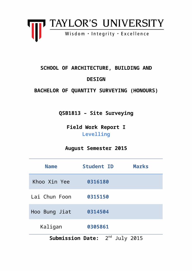
Content Page
Cover Page 1
Table of Content 2
1.0 Introduction to Leveling 3
1.1 Definition of Leveling 3 - 4
1.2 Definition of Terms Used in Leveling 4 - 6
1.3 Differential Leveling 7 - 8
1.4 Vertical Control Surveys 9 - 10
1.5 Arithmetical Check 10
2.0 Outline of Apparatus 11
2.1 Automatic Level 11 - 12
2.2 Adjustable Leg-Tripod 13 -14
2.3 Leveling Rod 14 - 15
2.4 Optical Plummet 16
2.5 Bull’s Eye Level 17
3.0 Objectives 18
4.0 Leveling Fieldwork 19
5.0 Field Data 20 - 21
5.1 Rise and Fall Method 20 - 21
6.0 Adjusted Data 22
6.1 Rise and Fall Method 22
7.0 Conclusion 23
8.0 Discussion and Recommendation 24
1.0 Introduction To Leveling
1.1 Definition of Leveling
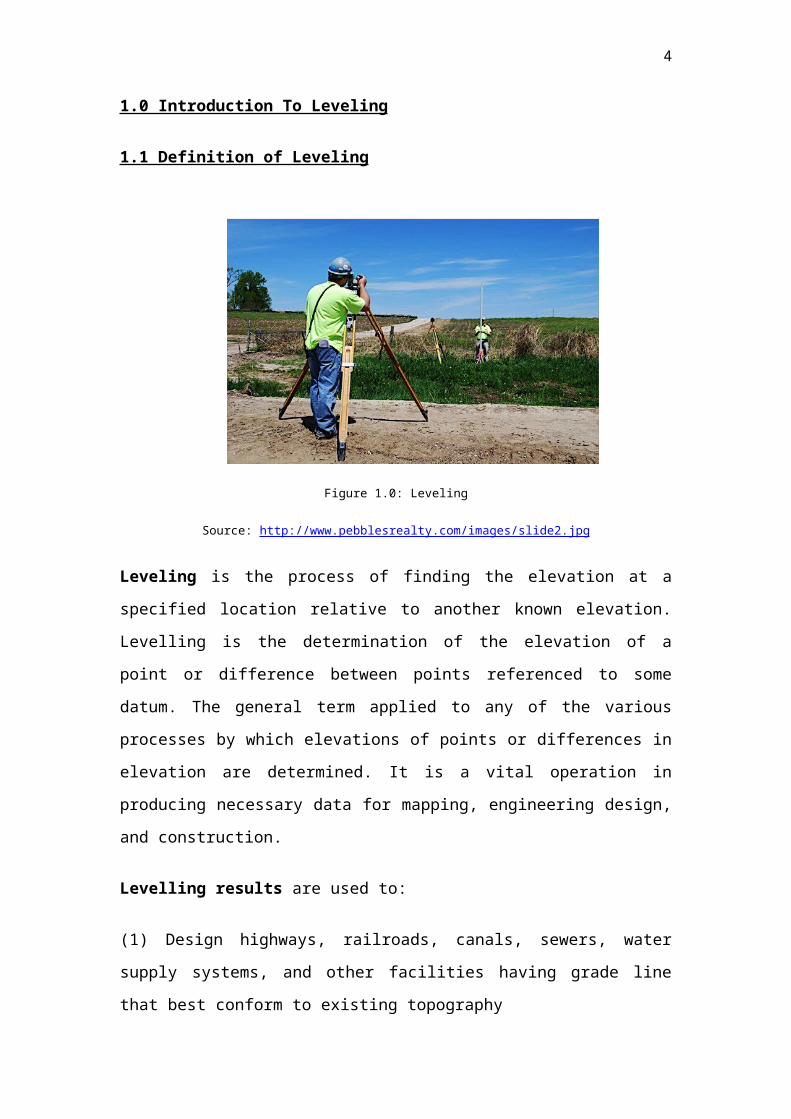
Figure 1.0: Leveling
Source: http://www.pebblesrealty.com/images/slide2.jpg
Leveling is the process of finding the elevation at a specified location relative
to another known elevation. Levelling is the determination of the elevation of a
point or difference between points referenced to some datum. The general
term applied to any of the various processes by which elevations of points or
differences in elevation are determined. It is a vital operation in producing
necessary data for mapping, engineering design, and construction.
Levelling results are used to:
(1) Design highways, railroads, canals, sewers, water supply systems, and
other facilities having grade line that best conform to existing topography
(2) Lay out construction projects according to planned elevations
(3) Calculate volumes of earthwork and other materials
(4) Investigate drainage characteristics of an area
(5) Develop maps showing general ground configurations
3
(6) Study earth subsidence and crustal motion
1.2 Definition Of Term Used in Leveling
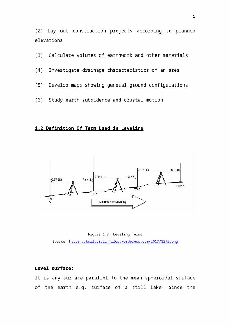
Figure 1.3: Leveling Terms
Source: https://buildcivil.files.wordpress.com/2013/12/2.png
Level surface:
It is any surface parallel to the mean spheroidal surface of the earth e.g.
surface of a still lake. Since the earth is an oblate spheroid, a level surface
may be regarded as a curved surface, every point on which is equidistant
from the center of the earth. It is normal to the plumb line at all points.
Level line:
It is a line lying in a level surface. It is therefore, normal to the plumb line at
all points.
Horizontal plane:
It is a plane tangential to the level surface at that point. It is perpendicular to
direction of gravity (plumb line).
4
Horizontal line:
It is any line lying in the horizontal plane. It is a straight line tangential to a
level line.
Vertical line:
It is a line normal to the level surface through that point e. g. a plumb line.
Vertical plane:
It is a plane containing a vertical line.
Vertical angle:
Angle between two intersecting lines in a vertical plane, one of the two lines is
commonly taken as horizontal in surveying.
Datum surface or line:
It is any arbitrarily assumed level surface or line from which vertical distances
are measured in India the datum adopted for G.T.S. bench marks is the mean
sea level at Karachi now in Pakistan.
Elevation:
It is vertical distance of a point above or below the datum. It is also known as
the reduced level. (R.L.) The elevation of a point is plus or minus according as
the point is above or below the datum.
Difference in elevation (H):
It is the vertical distance between the level surfaces passing through the two
different points.
Bench-mark (B.M.):
It is fixed reference point of known elevation.
Temporary benchmark (T.B.M.):
A bench-mark set up by the surveyor for his own use for particular task.
5
The line of collimation:
It is the line joining the intersection of cross hairs of the optical center of the
object glass. It is also called the line of sight.
An axis of the telescope:
It is a line joining the optical center of the object glass to the center of the eye
piece.
Foresight (F.S.):
It is also called foresight reading. It is a staff (or rod) reading on a point whose
elevation is to be determined or on a change point. It is also termed as minus
sight. It is the last staff reading denoting the shifting of the instrument.
Intermediate Sight (I. S.):
It is any other staff reading taken on appoint of unknown elevation from the
same set up of the level. All sights taken between the back sight and the fore
sight and the foresight are intermediate sights.
Change Point (C. P.) or Turning Point:
It is appoint denoting the shifting of the level. It is a point on which is the fore
and back sights are taken. Any stable and well defined object such as a
boundary stone, curb stone rail, rock etc. is used as a change point. A bench
mark may also be taken as a changer point.
A Station:
It is a point whose elevation is to be determined. It may be noted that it is a
point where the staff is held not the point where they leveled is set up.
Height of instrument (H. L):
It is the elevation (or the R.L.) of the plane of collimation (or plane of sight)
when the instrument is correctly leveled. It is also called the height of plane of
the collimation.
1.3 Differential Leveling
6
Differential leveling is the process of measuring vertical distances from a
known elevation point to determine elevations of unknown points. The most
common methods to determine elevation are through the use of:
A compensator type, automatic (engineering level) and level rod(s).
An electronic digital barcode leveling instrument with barcode rod.
A thorough knowledge of leveling principles and proper application of
methods and equipment will prevent costly delays and generate the needed
results and accuracy.
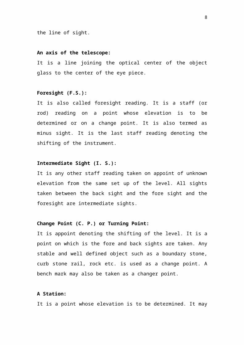
Figure: 1.4: Illustration of Differential Level
Source: http://onlinemanuals.txdot.gov/txdotmanuals/ess/images/ess_fig4-3_differential_leveling.jpg
The method in Figure 1.4 uses the difference in elevation between a known
elevation and the height of the instrument, and then the difference in elevation
from the height of instrument to an unknown elevation point.
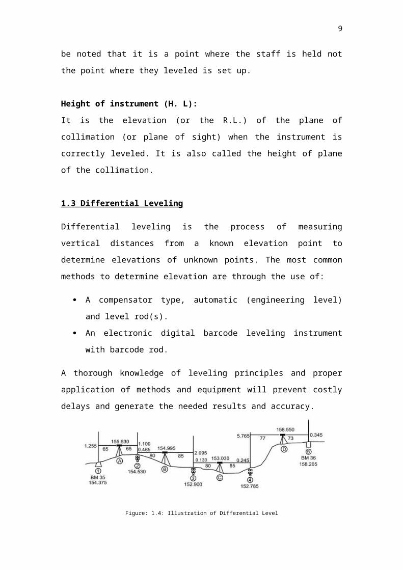
A Summary of the Differential Process
A Level is setup between two points, one whose elevation is known.
Figure 1.5: Differential Leveling ProcessSource: http://jerrymahun.com/library/Elev/b.htm#B
A backsight (BS) reading is taken on the known point to determine how
7
far above it the LoS is. Adding the BS reading to the point elevation
gives the elevation of the instrument (EI).
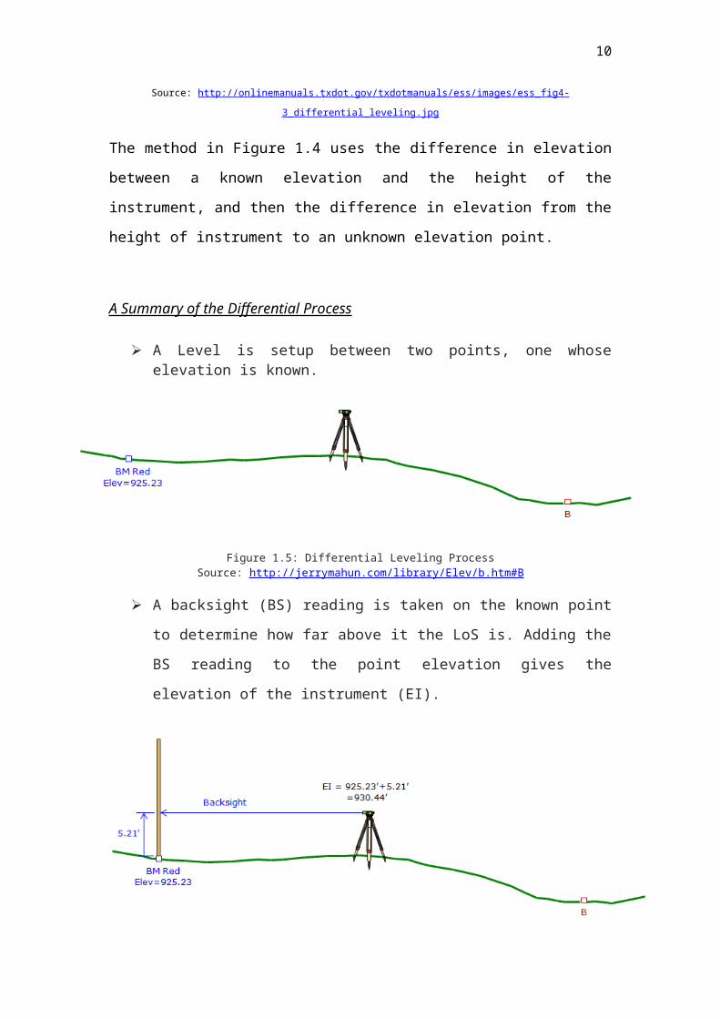
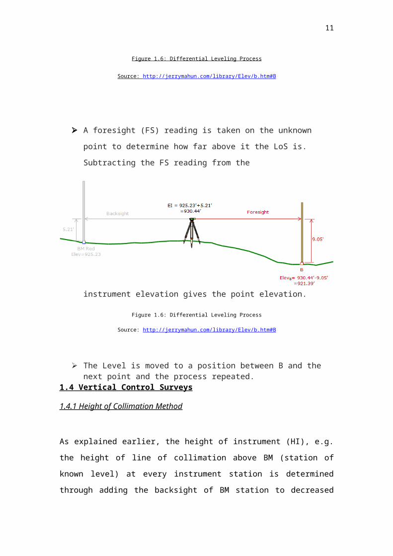
Figure 1.6: Differential Leveling Process
Source: http://jerrymahun.com/library/Elev/b.htm#B
A foresight (FS) reading is taken on the unknown point to determine
how far above it the LoS is. Subtracting the FS reading from the
instrument elevation gives the point elevation.
Figure 1.6: Differential Leveling Process
Source: http://jerrymahun.com/library/Elev/b.htm#B
The Level is moved to a position between B and the next point and the process repeated.
1.4 Vertical Control Surveys
8
1.4.1 Height of Collimation Method
As explained earlier, the height of instrument (HI), e.g. the height of line of
collimation above BM (station of known level) at every instrument station is
determined through adding the backsight of BM station to decreased level of
BM. From this height of instrument at a particular instrument station,
decreased levels of all the station points on ground are computed through
substracting foresight of that particular station from HI, i.e.
HI of instrument = RL of Bench mark + BS of BM
RL of intermediate point = HI - FS at intermediate station = HI - IS
While the instrument is shifted to its second position, height of instrument at
new set up station is needed to be determined. This is achieved through
correlating the levels of two collimation planes (first and second position)
through foresight of change point from first setup station and backsight of
same change point from second setup station, as given below:
RL of change point C = RL of A + BS at A - FS at C
HI (at second station O2) = RL of C + BS at C
With instrument set up at second station (say O2), staff readings at new
system of intermediate stations are taken before shifting the instrument at
next set up station (O3). This process is continuously repeated till the
levelling exercise is done, and all the required decreased levels are acquired.
1.4.2 Rise and Fall Method
On the other hand of finding the instrument height at a setup station, the
difference between consecutive points is obtained from their staff readings
with that immediately preceding it. The difference denotes a rise or a fall. The
decrease level of each point is then acquired by adding the rise to or
subtracting the fall from the RL of the preceding point. The arithmetic check in
9
this method is as follows:
∑ BS - ∑ FS = ∑ Rise - ∑ Fall
= Last RL - First RL
1.5 Arithmetical Check
An arithmetical check should be applied either at the end of the operation or
the end of each page when entries are carried forward over several pages to
avoid any possible error.
1.5.1 Height of collimation method
The sum of each collimation height multiplied by the number of reduced
levels obtained from it is equal to the sum of all the intermediate sights,
foresights and reduced levels excluding the first reduced level.
∑(BS) – ∑(FS) = Last RL – First RL
1.5.2 Rise and fall method
The sum of the back-sights minus the sum of the foresight is equal to the sum
of the rises minus the sum of the falls and is also equal to the first reduced
level minus the last reduced level.
∑(BS) – ∑(FS) = ∑(R) – ∑(F) = Last RL – First RL
10
2.0 Outline of Apparatus
2.1 Automatic Level
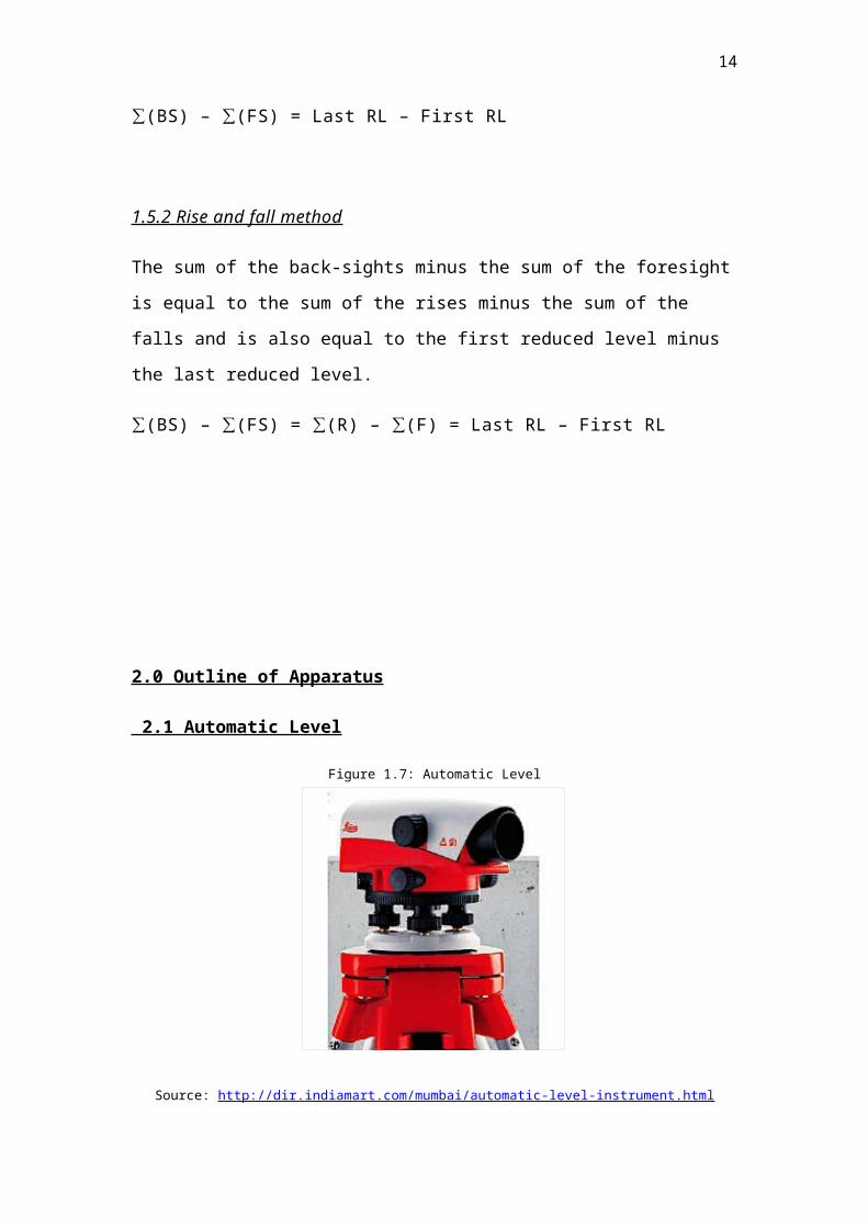
Figure 1.7: Automatic Level
Source: http://dir.indiamart.com/mumbai/automatic-level-instrument.html
Automatic level is designed for surveyors, builders, engineers, and other
construction professionals. It is a self-leveling optical instrument for accurately
measuring horizontal planes and angles at both long and short distances.
Quick to set up and easy to use, an automatic level instrument has a built-in
compensator that takes over and precisely levels itself.
It gets its name from an internal compensation system which maintains a
horizontal LoS automatically if the instrument is disturbed. The compensation
system consists of combinations of fixed and free swinging prisms and
mirrors.
When the instrument is level the LoS is horizontal. The cross-sectional view in
Figure 1.7 shows how the incoming horizontal LoS is reflected and refracted
and emerges at the eyepiece in a parallel path.
11
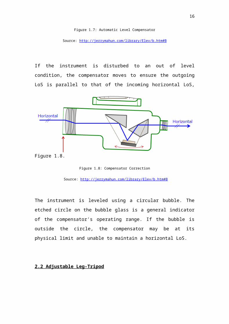
Figure 1.7: Automatic Level Compensator
Source: http://jerrymahun.com/library/Elev/b.htm#B
If the instrument is disturbed to an out of level condition, the compensator
moves to ensure the outgoing LoS is parallel to that of the incoming horizontal
LoS, Figure 1.8.
Figure 1.8: Compensator Correction
Source: http://jerrymahun.com/library/Elev/b.htm#B
The instrument is leveled using a circular bubble. The etched circle on the
bubble glass is a general indicator of the compensator's operating range. If
the bubble is outside the circle, the compensator may be at its physical limit
and unable to maintain a horizontal LoS.
2.2 Adjustable Leg-Tripod
12
Figure 1.9: Tripod
Source: http://www.allenprecision.com/survey/robotic-total-stations/accessories/tripods
A tripod is a three-legged support platform for the level. The tripod's
primary material can be wood, metal, fiberglass, or plastic; its legs fixed length
or extendable. A tripod usually has a flat top and a mounting screw for
instrument attachment. The primary function of the tripod is to ensure a stable
instrument setup for reliable measurements.
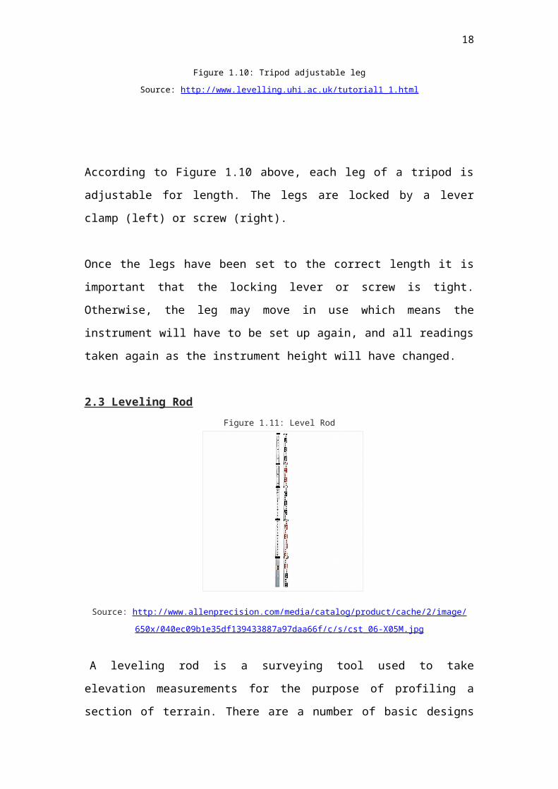
Figure 1.10: Tripod adjustable leg
Source: http://www.levelling.uhi.ac.uk/tutorial1_1.html
13
According to Figure 1.10 above, each leg of a tripod is adjustable for length.
The legs are locked by a lever clamp (left) or screw (right).
Once the legs have been set to the correct length it is important that the
locking lever or screw is tight. Otherwise, the leg may move in use which
means the instrument will have to be set up again, and all readings taken
again as the instrument height will have changed.
2.3 Leveling Rod
Figure 1.11: Level Rod
Source: http://www.allenprecision.com/media/catalog/product/cache/2/image/650x/
040ec09b1e35df139433887a97daa66f/c/s/cst_06-X05M.jpg
A leveling rod is a surveying tool used to take elevation measurements for the
purpose of profiling a section of terrain. There are a number of basic designs
available, including versions for optical and digital sighting and record
keeping.
The rod can be constructed of wood, metal, or fiberglass. Most rods telescope
or extend in order to allow large elevation differences yet collapse into a
compact form. There are many width and gradation styles depending on
application.
The most universal design is the Philadelphia rod, a portion of which is shown
in Figure 1.11.
14
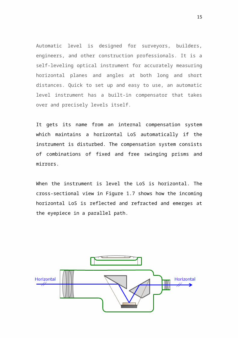
Figure 1.12: Philadelphia Rod
Source: http://jerrymahun.com/library/Elev/b.htm
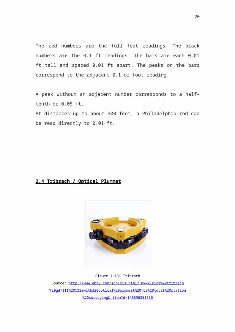
The red numbers are the full foot readings. The black numbers are the 0.1 ft
readings. The bars are each 0.01 ft tall and spaced 0.01 ft apart. The peaks
on the bars correspond to the adjacent 0.1 or foot reading.
A peak without an adjacent number corresponds to a half-tenth or 0.05 ft.
At distances up to about 300 feet, a Philadelphia rod can be read directly to
0.01 ft.
15
2.4 Tribrach / Optical Plummet
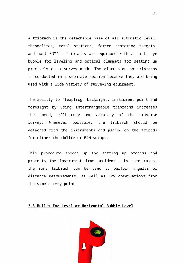
Figure 1.13: Tribrach
Source: http://www.ebay.com/sch/sis.html?_nkw=leica%20tribrach%20gdf111%201%20with%20optical
%20plummet%20for%20total%20station%20surveying&_itemId=140696351530
A tribrach is the detachable base of all automatic level, theodolites, total
stations, forced centering targets, and most EDM’s. Tribrachs are equipped
with a bulls eye bubble for leveling and optical plummets for setting up
precisely on a survey mark. The discussion on tribrachs is conducted in a
separate section because they are being used with a wide variety of surveying
equipment.
The ability to "leapfrog" backsight, instrument point and foresight by using
interchangeable tribrachs increases the speed, efficiency and accuracy of the
traverse survey. Whenever possible, the tribrach should be detached from the
instruments and placed on the tripods for either theodolite or EDM setups.
This procedure speeds up the setting up process and protects the instrument
from accidents. In some cases, the same tribrach can be used to perform
angular or distance measurements, as well as GPS observations from the
same survey point.
2.5 Bull’s Eye Level or Horizontal Bubble Level
16
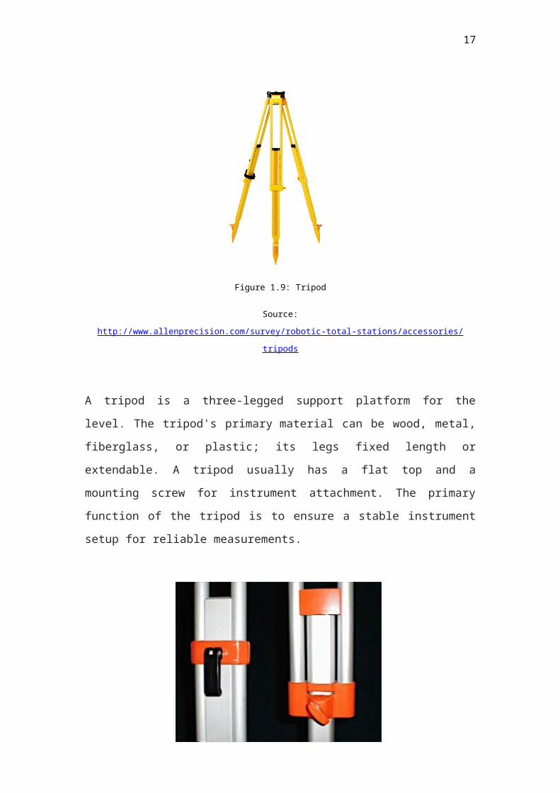
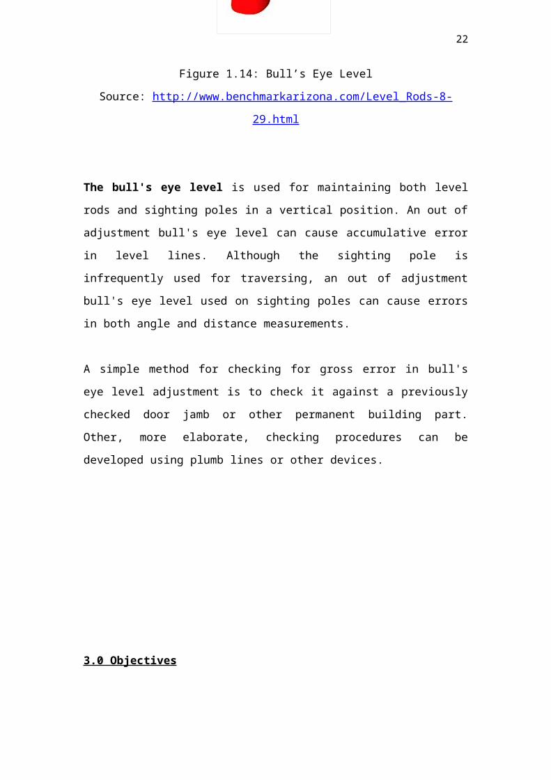
Figure 1.14: Bull’s Eye Level
Source: http://www.benchmarkarizona.com/Level_Rods-8-29.html
The bull's eye level is used for maintaining both level rods and sighting poles
in a vertical position. An out of adjustment bull's eye level can cause
accumulative error in level lines. Although the sighting pole is infrequently
used for traversing, an out of adjustment bull's eye level used on sighting
poles can cause errors in both angle and distance measurements.
A simple method for checking for gross error in bull's eye level adjustment is
to check it against a previously checked door jamb or other permanent
building part. Other, more elaborate, checking procedures can be developed
using plumb lines or other devices.
3.0 Objectives
To learn the basic levelling principles, theory and applications and to
be able to book and reduce the levelling data.
To enhance the students’ knowledge in the leveling procedure.
To experience the measurement of vertical distance by leveling.
To understand the correct method of setting up automatic level, tripod
stand and other instruments.
To take and record back sight (BS), intermediate sight (IS) and fore
sight (FS) with the corrected readings.
17
To understand the bookings in leveling.
To learn and undertake site measurements and calculations using
proper equation table.
To determine the error of misclosure in order to determine if the
leveling is acceptable.
To identify the reduced level of each staff station.
To plot a longitudinal profile and cross section with a suitable scale.
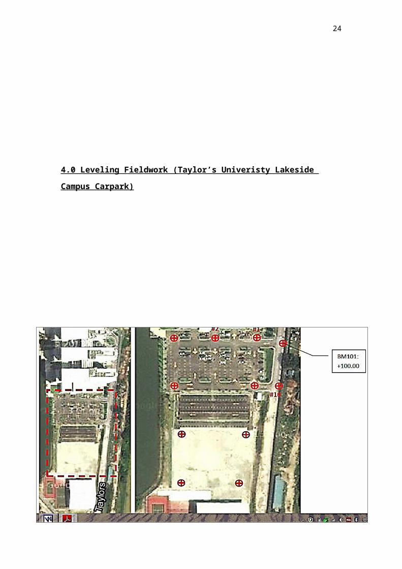
4.0 Leveling Fieldwork (Taylor’s Univeristy Lakeside Campus Carpark)
18
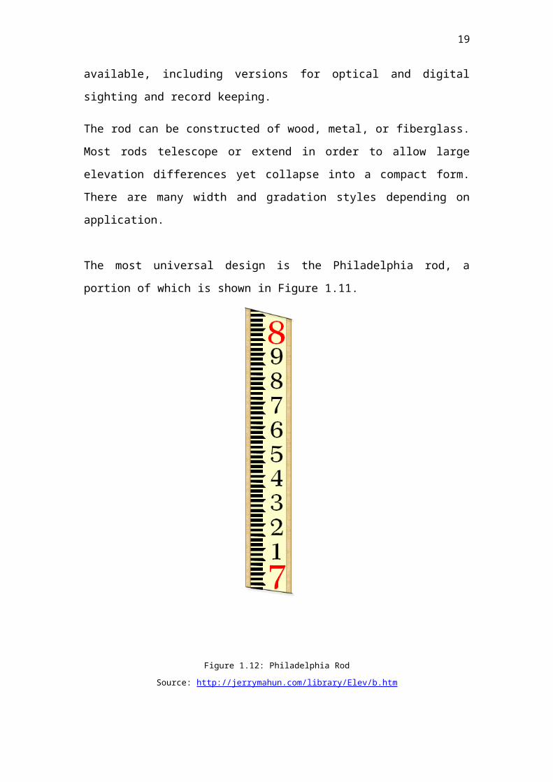
Figure 1.14: Fieldwork (Carpark) – plan of the checkpoints
Source: http://dearasis.blogspot.com/2010/02/taylors-lakeside-campus.html
5 .0 Field Data
5.1 Rise and Fall Method
19
Arithmetical Check:
20
BS IS FS Rise Fall R.L. Remarks
1.116 100.000 BM 1
3.231 0.974 0.142 100.142 TP 1
1.086 1.159 2.072 102.214 TP 2
1.026 1.189 0.103 102.111 TP 3
1.391 1.059 0.033 102.078 TP 4
0.726 1.094 0.297 102.375 TP 5
1.101 0.979 0.253 102.122 TP 6
1.186 0.904 0.197 102.319 TP 7
1.126 1.234 0.048 102.271 TP 8
0.996 0.969 0.157 102.428 TP 9
0.951 3.359 2.363 100.065 TP 10
0.999 0.048 100.017 BM 1
∑BS=13.936 ∑FS=13.919 ∑Rise=2.865 ∑Fall=2.848
∑BS - ∑FS = ∑Rise - ∑Fall = Last Reduced Level Reading - First
Reduced Level Reading
∑BS - ∑FS = 13.936 – 13.919
= + 0.017
∑Rise - ∑Fall = 2.865 - 2.848
= + 0.017
Last Reduced Level Reading - First Reduced Level Reading
100.017 - 100.000 = + 0.017
Acceptable Misclosure = ±12√k
K= the number of set-ups
±12√11 = 39.799 mm
(* If the error is bigger than 39.799 mm, then the levelling is not acceptable)
Therefore, the leveling is acceptable.
6.0 Adjusted Data
6.1 Rise and Fall Method
21
Correction = Cumulative distance ÷ Total distance × Error
Correction per set-up
= Error of misclosure ÷ Number of set up
= (100.0000 - 100.017) ÷ 11
= - 0.0015 m
7.0 Conclusion
22
BS IS FS Rise Fall R.L. Adj. Final
R.L.
Remarks
1.116 100.000 100.000 BM 1
3.231 0.974 0.142 100.142 -0.0015 100.141 TP 1
1.086 1.159 2.072 102.214 -0.0030 102.211 TP 2
1.026 1.189 0.103 102.111 -0.0045 102.066 TP 3
1.391 1.059 0.033 102.078 -0.0060 102.072 TP 4
0.726 1.094 0.297 102.375 -0.0075 102.368 TP 5
1.101 0.979 0.253 102.122 -0.0090 102.113 TP 6
1.186 0.904 0.197 102.319 -0.0105 102.309 TP 7
1.126 1.234 0.048 102.271 -0.0120 102.259 TP 8
0.996 0.969 0.157 102.428 -0.0135 102.415 TP 9
0.951 3.359 2.363 100.065 -0.0150 100.050 TP 10
0.999 0.048 100.017 -0.0170 100.000 BM 1
In this leveling fieldwork, we have learnt the procedure of leveling throughout
the car park area. Initially, the given reduced level of Bench Mark 1 (BM 1) is
100.00 m.
The leveling process begins with obtaining the backsight (BS) of BM1 and the
foresight (FS) of turning point 1 (TP 1). Then we shifted the auto level to
obtain the backsight (BS) of turning point (TP 1) and the foresight (FS) of
turning point 2 (TP 2). This process is repeated by shifting the auto level to
obtain the backsight (BS) and foresight (FS) of the following staff stations.
After that we went back to Bench Mark 1 (BM 1) in order to obtain its FS in
order to calculate the error of misclosure.
After completed the leveling, we decided to use the rise and fall method to
calculate the reduced level of each staff station. Our error of collected data
misclosure is 0.018 mm. According to the third order of accuracy, the
maximum allowable error of closure is ±39.80mm by using the formulae of
±12√k, where k represents the number of set-ups. Thus, our leveling result is
acceptable.
Hence, the reduced level is able to be equivalent to the benchmark given
which is 100.00 m by distributing the error to each set-up.
As a future Quantity Surveyor, it is essential for us to learn some of the
knowledge of site surveying which is inter-related to the construction process.
Surveying is the technique, profession, and science of determining the
dimensions and contour of the Earth's surface.
Using specialized surveying equipment such as automatic level, leveling rod,
tripod and so on, professional surveyors determine land boundaries for a
variety of important reasons. One of the most common reasons for a
consumer to acquire the assistance of a surveyor is the acquisition of a new
piece of land, as it has to be legally determined where one person's property
ends and another begins for government issued deeds. Additionally,
surveyors work with cartographers to create accurate maps.
8.0 Discussion and Recommendation
23
1 Avoid taking measurement near magnetic sources such as hand phone,
watch, electric cable and etc.
2 Make sure the bubbles are properly level.
3 Triple check with the work and reading.
4 Make sure the plum bob properly centered over the peg.
24