Embed Size (px)
Citation preview
SKF high-capacity cylindrical roller bearingsFull complement bearings with a cage
Higher load ratings and longer service life
Applications like industrial gearboxes, gear-boxes in wind turbines or machines for min-ing equipment require components that can provide high operational reliability and long service life. In these applications, load carry-ing capacity is particularly important, which is the reason why full complement bearings are frequently used.
Full complement bearings do not have a cage separating the rollers, which enables a maximum number of rollers.
Therefore, the advantage of full comple-ment bearings is that they can accommo-date much heavier loads than same-sized bearings with a cage.
However, direct roller-to-roller contact in a full complement bearing increases friction, heat generation and the risk for wear. Con-sequently, the permissible speed is reduced. Under particularly difficult operating condi-tions, these disadvantages quickly add up to substantially reduced bearing service life.
To achieve the maximum load carrying capacity of a full complement bearing and the robust performance of a bearing with a cage, SKF developed high-capacity cylindrical roller bearings. These bearings combine the advantages of both bearing types.
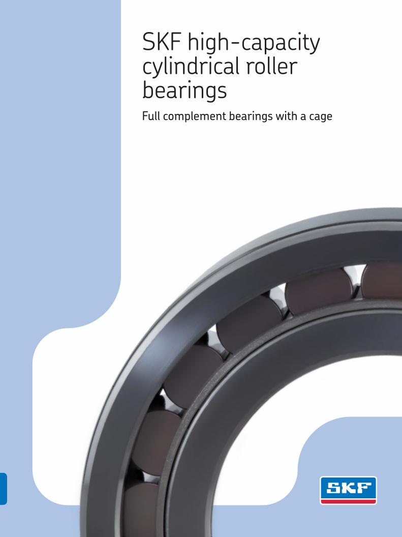
SKF high-capacity cylindrical roller bearings with an inner ring or outer ring shoulder-guided cage
2
An innovative bearing design
Traditionally, higher load carrying capacities have been achieved by incorporating larger rollers. However, to do this within the ISO standardized boundary dimensions requires thinner rings. Thinner rings increase the risk of ring creep, ring or flange cracks, and fret-ting corrosion. Also, larger rollers are more prone to smearing due to increased inertial forces.
The new SKF high-capacity cylindrical roller bearings († fig. 1), which contain more rollers than EC design cylindrical roller bearings, not only maintain the original ISO boundary dimensions, they also maintain the internal geometry of the EC design. The result: increased dynamic and static load carrying capacities and consequently longer bearing service life.
Reduced risk of roller slidingSKF high-capacity cylindrical roller bearings are specially designed to accommodate the requirements of wind turbines and applica-tions where high load carrying capacity is a prerequisite. In these applications bearings must frequently operate below the requisite minimum load. Under these conditions, the inertial forces of the rollers and cage, and the friction in the lubricant, can have a det-rimental effect on the rolling conditions in the bearing arrange ment and may cause damaging sliding movement between the rollers and raceways.
With the inner ring shoulder-guided cage of SKF high-capacity cylindrical roller bear-ings, this risk is reduced. When operating
below the recommended minimum radial load, the sliding ratio for these bearings with an inner ring shoulder-guided cage is sig-nificantly lower than for conventional cylin-drical roller bearings with a cage of the same size. For bearings in the 22 dimension series, the risk for sliding damage is even more reduced than for 23 series bearings. 22 series bearings have a lower cross sec-tion and smaller rollers, which results in lower inertial forces.
The rollers are coated with black oxide to further reduce the risk of sliding damage inside the bearing during initial start-up.
A sustainable productSKF high-capacity cylindrical roller bearings were designed to support SKF’s Beyond Zero sustainability efforts. Through this initiative, SKF is committed to creating products that consume less energy when in use than the energy needed to manufac-ture them.
From an environmental standpoint, these bearings can provide the following benefits:
lower • frictional lossespossibility for downsizing•increased bearing service life•
The components of SKF high-capacity cylindrical roller bearings are all made of steel, enabling easy recycling.
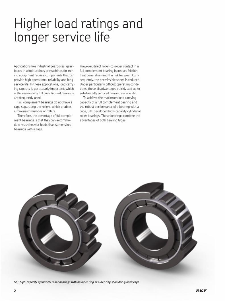
Cross section of an SKF high-capacity cylindrical roller bearing
Fig. 1
3
Performance advantage
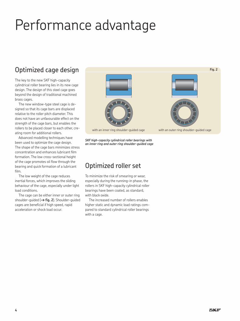
Optimized cage designThe key to the new SKF high-capacity cylindrical roller bearing lies in its new cage design. The design of this steel cage goes beyond the design of traditional machined brass cages.
The new window-type steel cage is de-signed so that its cage bars are displaced relative to the roller pitch diameter. This does not have an unfavourable effect on the strength of the cage bars, but enables the rollers to be placed closer to each other, cre-ating room for additional rollers.
Advanced modelling techniques have been used to optimize the cage design. The shape of the cage bars minimizes stress concentration and enhances lubricant film formation. The low cross-sectional height of the cage promotes oil flow through the bearing and quick formation of a lubricant film.
The low weight of the cage reduces inertial forces, which improves the sliding behaviour of the cage, especially under light load conditions.
The cage can be either inner or outer ring shoulder-guided († fig. 2). Shoulder-guided cages are beneficial if high speed, rapid acceleration or shock load occur.
Optimized roller setTo minimize the risk of smearing or wear, especially during the running-in phase, the rollers in SKF high-capacity cylindrical roller bearings have been coated, as standard, with black oxide.
The increased number of rollers enables higher static and dynamic load ratings com-pared to standard cylindrical roller bearings with a cage.
SKF high-capacity cylindrical roller bearings with an inner ring and outer ring shoulder-guided cage
Fig. 2
with an inner ring shoulder-guided cage with an outer ring shoulder-guided cage
4
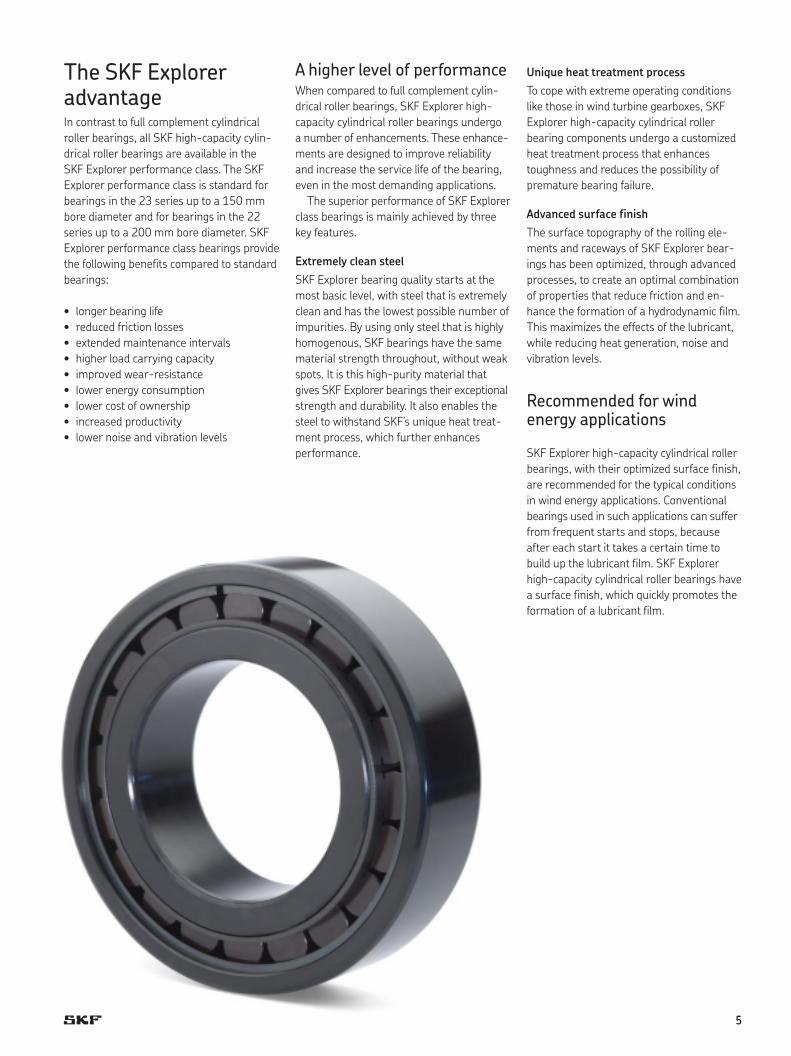
The SKF Explorer advantageIn contrast to full complement cylindrical roller bearings, all SKF high-capacity cylin-drical roller bearings are available in the SKF Explorer performance class. The SKF Explorer performance class is standard for bearings in the 23 series up to a 150 mm bore diameter and for bearings in the 22 series up to a 200 mm bore diameter. SKF Explorer performance class bearings provide the following benefits compared to standard bearings:
longer bearing life•reduced • friction lossesextended maintenance intervals•higher load carrying capacity•improved wear-resistance•lower energy consumption•lower cost of ownership•increased productivity•lower noise and vibration levels•
A higher level of performanceWhen compared to full complement cylin-drical roller bearings, SKF Explorer high- capacity cylindrical roller bearings undergo a number of enhancements. These enhance-ments are designed to improve reliability and increase the service life of the bearing, even in the most demanding applications.
The superior performance of SKF Explorer class bearings is mainly achieved by three key features.
Extremely clean steelSKF Explorer bearing quality starts at the most basic level, with steel that is extremely clean and has the lowest possible number of impurities. By using only steel that is highly homogenous, SKF bearings have the same material strength throughout, without weak spots. It is this high-purity material that gives SKF Explorer bearings their exceptional strength and durability. It also enables the steel to withstand SKF’s unique heat treat-ment process, which further enhances performance.
Unique heat treatment processTo cope with extreme operating conditions like those in wind turbine gearboxes, SKF Explorer high-capacity cylindrical roller bearing components undergo a customized heat treatment process that enhances toughness and reduces the possibility of premature bearing failure.
Advanced surface finishThe surface topography of the rolling ele-ments and raceways of SKF Explorer bear-ings has been optimized, through advanced processes, to create an optimal combination of properties that reduce friction and en-hance the formation of a hydrodynamic film. This maximizes the effects of the lubricant, while reducing heat generation, noise and vibration levels.
Recommended for wind energy applications
SKF Explorer high-capacity cylindrical roller bearings, with their optimized surface finish, are recommended for the typical conditions in wind energy applications. Conventional bearings used in such applications can suffer from frequent starts and stops, because after each start it takes a certain time to build up the lubricant film. SKF Explorer high-capacity cylindrical roller bearings have a surface finish, which quickly promotes the formation of a lubricant film.
5
Functionality and long-term tests
Light-load testFocusing only on high load carrying capacity becomes risky if loads can vary and drop below the required minimum load. This is even more critical at high speeds where the roller-slip ratio (relative sliding between the rollers and raceways) can increase.
Under these high-speed, light-load con-ditions, the inertial forces, combined with inadequate lubrication, can substantially increase the risk of smearing, which can quickly cause bearings to fail. Therefore, SKF high-capacity cylindrical roller bearings were also tested under minimum load con-ditions to determine the level of roller and cage slip.
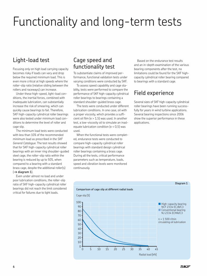
The minimum load tests were conducted with less than 10% of the recommended minimum load as prescribed in the SKF General Catalogue. The test results showed that for SKF high-capacity cylindrical roller bearings with an inner ring shoulder-guided steel cage, the roller-slip ratio within the bearing is reduced by up to 50%, when compared to a bearing with a standard brass cage, despite the additional roller(s) († diagram 1).
Even under almost no load and under poor lubrication conditions, the roller-slip ratio of SKF high-capacity cylindrical roller bearings did not reach the limit considered critical for failures due to light loads.
Cage speed and functionality testTo substantiate claims of improved per-formance, functional validation tests under varying conditions were conducted by SKF.
To assess speed capability and cage sta-bility, tests were performed to compare the performance of SKF high-capacity cylindrical roller bearings to bearings containing a standard shoulder-guided brass cage.
The tests were conducted under different lubrication conditions. In one case, oil with a proper viscosity, which provides a suffi-cient oil film (k > 1,5) was used. In another test, a low-viscosity oil to simulate an inad-equate lubrication condition (k < 0,5) was used.
When the functional tests were complet-ed, endurance tests were conducted to compare high-capacity cylindrical roller bearings with standard design cylindrical roller bearings containing a brass cage. During all the tests, critical performance parameters such as temperature, loads, speed and vibration levels were monitored continuously.
Based on the endurance test results and an in-depth examination of the various bearing components after the test, no limitations could be found for the SKF high-capacity cylindrical roller bearing compared to bearings with a standard cage.
Field experienceSeveral sizes of SKF high-capacity cylindrical roller bearings have been running success-fully for years in wind turbine applications. Several bearing inspections since 2006 show the superior performance in these applications.
Diagram 1
Comparison of cage slip at different radial loads
100
90
80
70
60
50
40
30
20
10
00 5 10 15 20 25 30 35 40 45
Cage slip [%]
Radial load [kN]
n High-capacity bearing NCF 2334 ECJB/C3
n Conventional bearing NJ 2334 ECMA/C3
n = 1 500 r/mincirculating oil lubrication
6
Recommendations for bearing arrangement design
Load carrying capacity and lifeThe basic rating life, calculated in accord-ance with ISO 281:2007, is also applicable for SKF high-capacity cylindrical roller bear-ings. When comparing the calculated bear-ing life of a standard bearing with a cage to the life of a same-sized high-capacity bear-ing, there is a possibility of increasing bear-ing life up to 45%.
To take full advantage of the increased load carrying capacity and improved wear-resistance of SKF Explorer bearings, always use the SKF rating life method when calcu-lating bearing life. For additional information about bearing calculations, refer to the SKF General Catalogue or the SKF Interactive Engineering Catalogue, available online at www.skf.com.
FrictionFriction influences the heat generated by a bearing. The amount of friction depends on several factors such as load, speed, lubricant and others.
For SKF high-capacity cylindrical roller bearings, the frictional moment can be cal-culated with the new SKF model for calculat-ing a frictional moment. The model, which provides a more accurate result than stand-ard calculations, takes the lubricant, applied loads and bearing design into consideration. The calculations are complex but can be performed easily using the SKF Interactive Engineering Catalogue, available online at www.skf.com.
When calculating the frictional moment according to the SKF General Catalogue, the factors for bearings with a cage (N, NU, NJ or NUP designs) have to be used instead of the factors for full complement bearings (NCF or NJG designs).
Speed capabilityThe speed capability of a bearing depends on several factors, including the strength of the cage, the geometry of the rolling elements and raceways and the lubrication method.
The reference speeds listed in the product tables are the same for both standard and high-capacity cylindrical roller bearings.
The limiting speeds are much higher than those of full complement cylindrical roller bearings. If an SKF high-capacity cylindrical roller bearing has to be operated at higher speeds than the limiting speed, contact the SKF application engineering service.
Recommended fitsTolerances for the bore and outside diam-eter of rolling bearings are internationally standardized.
Therefore, SKF high-capacity cylindrical roller bearings have the same fits as stand-ard cylindrical roller bearings with a cage. The appropriate fit depends on the applica-tion, applied load, operating conditions and possible displacement of the inner ring. For the typical normal to heavy load applications, such as in wind turbines and other applica-tions where SKF high-capacity cylindrical roller bearings are used, very often a p6 or r6 shaft fit is recommended. With a p6 and r6 fit, radial clearance greater than Normal is recommended.
For additional information and fit recom-mendations, refer to the SKF General Catalogue.
LubricationSKF recommends oil lubrication for high-capacity cylindrical roller bearings because they have a shoulder-guided cage. The low cross-section of the cage and the unique shape of the cage pockets promote oil flow through the bearing and the formation of a lubricant film.
For grease lubricated applications, contact the SKF application engineering service.
7
Application examples
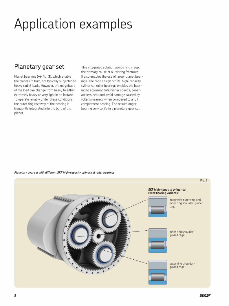
Planetary gear setPlanet bearings († fig. 3), which enable the planets to turn, are typically subjected to heavy radial loads. However, the magnitude of the load can change from heavy to either extremely heavy or very light in an instant. To operate reliably under these conditions, the outer ring raceway of the bearing is frequently integrated into the bore of the planet.
Fig. 3
Planetary gear set with different SKF high-capacity cylindrical roller bearings
SKF high-capacity cylindrical roller bearing variants:
outer ring shoulder-guided cage
inner ring shoulder-guided cage
integrated outer ring and inner ring shoulder-guided cage
This integrated solution avoids ring creep, the primary cause of outer ring fractures. It also enables the use of larger planet bear-ings. The cage design of SKF high-capacity cylindrical roller bearings enables the bear-ing to accommodate higher speeds, gener-ate less heat and avoid damage caused by roller smearing, when compared to a full complement bearing. The result: longer bearing service life in a planetary gear set.
8
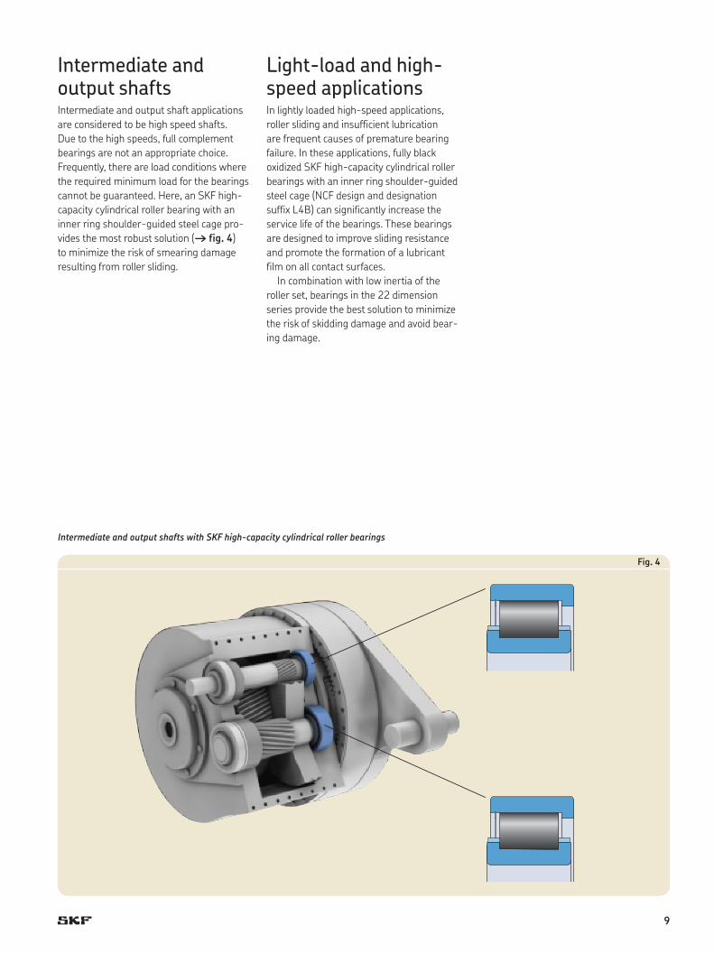
Fig. 4
Intermediate and output shafts with SKF high-capacity cylindrical roller bearings
Intermediate and output shafts Intermediate and output shaft applications are considered to be high speed shafts. Due to the high speeds, full complement bearings are not an appropriate choice. Frequently, there are load conditions where the required minimum load for the bearings cannot be guaranteed. Here, an SKF high-capacity cylindrical roller bearing with an inner ring shoulder-guided steel cage pro-vides the most robust solution († fig. 4) to minimize the risk of smearing damage resulting from roller sliding.
Light-load and high-speed applications In lightly loaded high-speed applications, roller sliding and insufficient lubrication are frequent causes of premature bearing failure. In these applications, fully black oxidized SKF high-capacity cylindrical roller bearings with an inner ring shoulder-guided steel cage (NCF design and designation suffix L4B) can significantly increase the service life of the bearings. These bearings are designed to improve sliding resistance and promote the formation of a lubricant film on all contact surfaces.
In combination with low inertia of the roller set, bearings in the 22 dimension series provide the best solution to min imize the risk of skidding damage and avoid bear-ing damage.
9
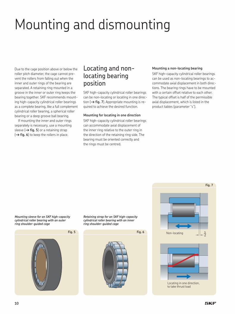
Fig. 7
s2
Mounting and dismounting
Due to the cage position above or below the roller pitch diameter, the cage cannot pre-vent the rollers from falling out when the inner and outer rings of the bearing are separated. A retaining ring mounted in a groove in the inner or outer ring keeps the bearing together. SKF recommends mount-ing high-capacity cylindrical roller bearings as a complete bearing, like a full complement cylindrical roller bearing, a spherical roller bearing or a deep groove ball bearing.
If mounting the inner and outer rings separately is necessary, use a mounting sleeve († fig. 5) or a retaining strap († fig. 6) to keep the rollers in place.
Locating and non-locating bearing positionSKF high-capacity cylindrical roller bearings can be non-locating or locating in one direc-tion († fig. 7). Appropriate mounting is re-quired to achieve the desired function.
Mounting for locating in one directionSKF high-capacity cylindrical roller bearings can accommodate axial displacement of the inner ring relative to the outer ring in the direction of the retaining ring side. The bearing must be oriented correctly and the rings must be centred.
Retaining strap for an SKF high-capacity cylindrical roller bearing with an inner ring shoulder-guided cage
Fig. 5 Fig. 6
Mounting sleeve for an SKF high-capacity cylindrical roller bearing with an outer ring shoulder-guided cage
Non-locating
Locating in one direction, to take thrust load
Mounting a non-locating bearingSKF high-capacity cylindrical roller bearings can be used as non-locating bearings to ac-commodate axial displacement in both direc-tions. The bearing rings have to be mounted with a certain offset relative to each other. The typical offset is half of the permissible axial displacement, which is listed in theproduct tables (parameter “s”).
s2
10
Designs
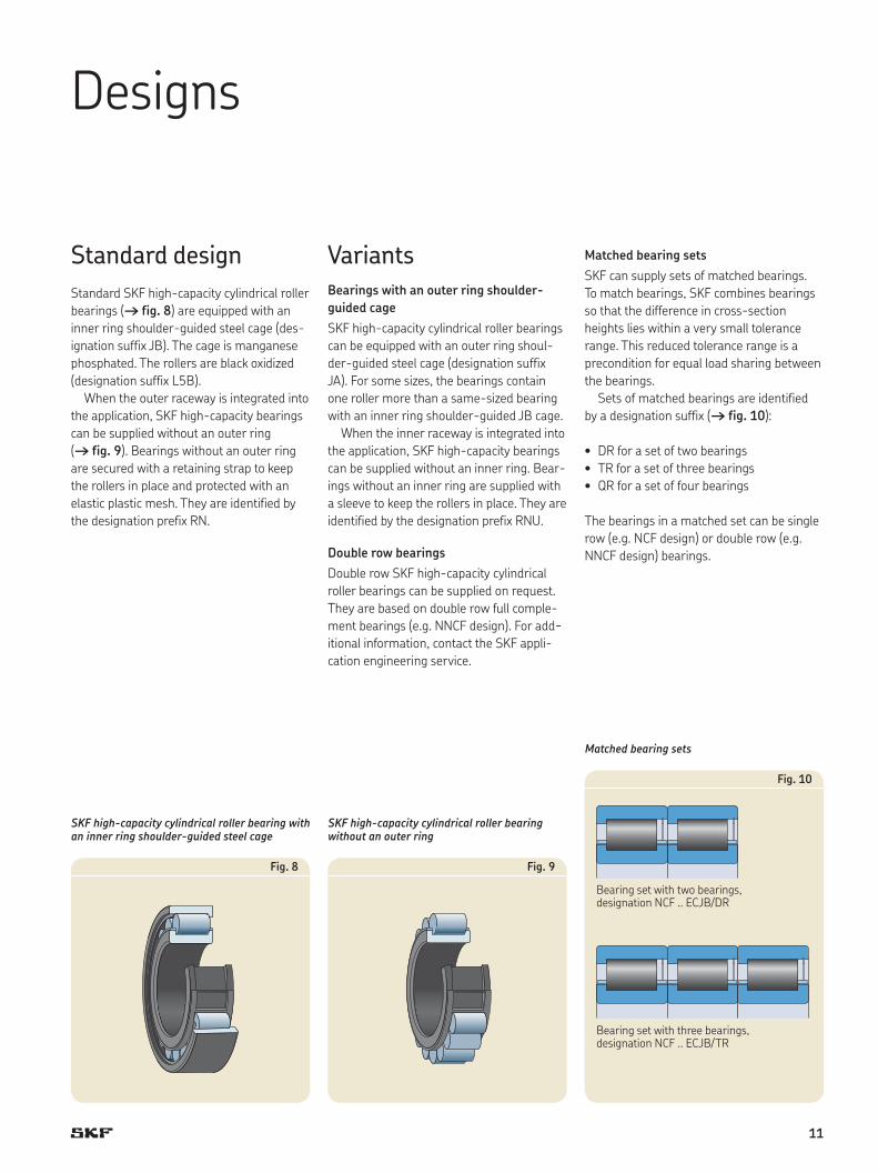
Standard designStandard SKF high-capacity cylindrical roller bearings († fig. 8) are equipped with an inner ring shoulder-guided steel cage (des-ignation suffix JB). The cage is manganese phosphated. The rollers are black oxidized (designation suffix L5B).
When the outer raceway is integrated into the application, SKF high-capacity bearings can be supplied without an outer ring († fig. 9). Bearings without an outer ring are secured with a retaining strap to keep the rollers in place and protected with an elastic plastic mesh. They are identified by the designation prefix RN.
SKF high-capacity cylindrical roller bearing with an inner ring shoulder-guided steel cage
Fig. 8
SKF high-capacity cylindrical roller bearing without an outer ring
Fig. 9
Matched bearing sets
Fig. 10
Bearing set with two bearings, designation NCF .. ECJB/DR
Bearing set with three bearings, designation NCF .. ECJB/TR
VariantsBearings with an outer ring shoulder-guided cageSKF high-capacity cylindrical roller bearings can be equipped with an outer ring shoul-der-guided steel cage (designation suffix JA). For some sizes, the bearings contain one roller more than a same-sized bearing with an inner ring shoulder-guided JB cage.
When the inner raceway is integrated into the application, SKF high-capacity bearings can be supplied without an inner ring. Bear-ings without an inner ring are supplied with a sleeve to keep the rollers in place. They are identified by the designation prefix RNU.
Double row bearingsDouble row SKF high-capacity cylindrical roller bearings can be supplied on request. They are based on double row full comple-ment bearings (e.g. NNCF design). For add-itional information, contact the SKF appli-cation engineering service.
Matched bearing sets SKF can supply sets of matched bearings. To match bearings, SKF combines bearings so that the difference in cross-section heights lies within a very small tolerance range. This reduced tolerance range is a precondition for equal load sharing between the bearings.
Sets of matched bearings are identified by a designation suffix († fig. 10):
DR for a set of two bearings•TR for a set of three bearings•QR for a set of four bearings•
The bearings in a matched set can be single row (e.g. NCF design) or double row (e.g. NNCF design) bearings.
11
Bearing data – general
SKF Explorer bearingsSKF Explorer high-capacity cylindrical roller bearings are available in the 22 series, up to a 200 mm bore, and in the 23 series, up to a 150 mm bore as standard. In the 22 series with the bore diameter 220 mm and in the 23 series from bore diameter 160 to 240 mm, both conventional and SKF Explorer bearings are available. The SKF Explorer bearings in this range are identified by the designation suffix PEX.
DimensionsThe boundary dimensions of SKF high- capacity cylindrical roller bearings are in ac-cordance with ISO 15:1998. The bearings are available in the 22 and 23 dimension series. Bearings in the 22 series have a bore diameter ranging from 140 to 220 mm. Bearings in the 23 dimension series have a bore diameter ranging from 130 to 240 mm. Other sizes or special dimensions are available on request.
TolerancesSKF high-capacity cylindrical roller bearings are manufactured to Normal tolerances for dimensional accuracy and to P6 tolerances for running accuracy. The tolerances are in accordance with ISO 492:2002.
Radial internal clearanceSKF high-capacity cylindrical roller bearings are manufactured with Normal radial clear-ance as standard. Other radial clearance classes, e.g. C3 are available on request.
Axial displacementSKF high-capacity cylindrical roller bearings can accommodate axial displacement of the shaft relative to the housing within certain limits. As the axial displacement takes place within the bearing and not between the bearing and shaft or housing bore, there is practically no increase in friction when the bearing rotates. Values for the permissible axial displacement from the normal pos ition of one bearing ring relative to the other are listed in the product tables (parameter “s”).
If an SKF high-capacity cylindrical roller bearing is used as a non-locating bearing in both directions, the bearing rings must be mounted with an offset relative to each other († page 10). The required offset and the maximum movement from the centre pos-ition is half of the permissible axial displace-ment, s.
MisalignmentThe ability of SKF high-capacity cylindrical roller bearings to accommodate angular misalignment of the inner ring relative to the outer ring is limited to 3 minutes of arc.This value applies to non-locating bearings, provided the position of the shaft and hous-ing axes remain constant. When the bear-ings are used to locate the shaft axially, the value must be reduced as uneven flange loading can lead to increased wear and increases the risk of flange fracture. For additional information, contact the SKF application engineering service.
Operating temperatureSKF high-capacity cylindrical roller bearings undergo a special heat treatment that ena-bles the bearings to accommodate tempera-tures up to 150 °C, provided the bearings are lubricated properly.
Minimum loadFor satisfactory operation, SKF high-capacity cylindrical roller bearings must always be subjected to a given minimum load.
The requisite minimum load to be applied to SKF high-capacity cylindrical roller bear-ings can be estimated using
q 4n w q dm w2Frm = kr 6 + —– –––– < nr z < 100 z
whereFrm = minimum radial load [kN]kr = minimum load factor 0,16 for bearings in the 22 series 0,20 for bearings in the 23 seriesn = rotational speed [r/min]nr = reference speed [r/min]dm = bearing mean diameter [mm] = 0,5 (d+D)
As shown in the section Light-load test († page 6), when operating below the recommended minimum load, the cage-slip of an SKF high-capacity cylindrical roller bearing with an inner ring shoulder-guided cage is significantly reduced compared to bearings with a standard cage.
12
Dynamic axial load carrying capacity
SKF high-capacity cylindrical roller bearings can support axial loads in one direction. Their axial load carrying capacity is primarily determined by the ability of the sliding sur-faces of the roller end / flange contact to support loads. Factors having the greatest effect on this ability are the lubricant, oper-ating temperature and the ability of the bearing to dissipate heat.
The dynamic axial load carrying capacity can be calculated as described in the SKF General Catalogue for single row cylindrical roller bearings. Calculations can be perform ed using the SKF Interactive Engineering catalogue, available online at www.skf.com.
To minimize the risk of flange fracture, the constantly acting axial load applied to the bearings should never exceed
Fa max = 0,0035 D1,7
When acting only occasionally and for brief periods, the axial load applied to the bear-ings should never exceed
Fa max = 0,0085 D1,7
whereFa max = maximum constantly or occasionally
acting axial load [kN]D = bearing outside diameter [mm]
For additional information about dynamic axial load carrying capacity, contact the SKF application engineering service.
Equivalent dynamic bearing load
For non-locating bearings
P = Fr
whereP = equivalent dynamic bearing load [kN]
If an SKF high-capacity bearing is used to locate the shaft in one direction, the equiva-lent dynamic bearing load should be calcu-lated using
P = Fr when Fa/Fr ≤ 0,3P = 0,92 Fr + 0,4 Fa when Fa/Fr > 0,3
Since axially loaded cylindrical roller bearings only operate satisfactorily when they are subjected to a simultaneously acting radial load, the ratio Fa/Fr should not exceed 0,5.
Equivalent static bearing loadP0 = Fr
whereP0 = equivalent static bearing load [kN]
Supplementary designationsIn addition to the designation suffixes that are listed in the SKF General Catalogue, the following designation suffixes are relevant for SKF high-capacity cylindrical roller bearings:
JB One-piece window-type steel cage, inner ring shoulder-guided
JA One-piece window-type steel cage, outer ring shoulder-guided
L4B Rollers and bearing rings black oxidized
L5B Rollers black oxidizedL7B Rollers and inner ring black oxidizedPEX SKF Explorer bearing, used only when
same-sized conventional and SKF Explorer bearings are available
DR Bearing set consisting of two matched bearings
TR Bearing set consisting of three matched bearings
QR Bearing set consisting of four matched bearings
For additional information, refer to the SKF General Catalogue or the SKF Interactive Engineering Catalogue, available online at www.skf.com.
13
s
d d1D1ED
B
r1r2
r1 r2r1r2
r1r2
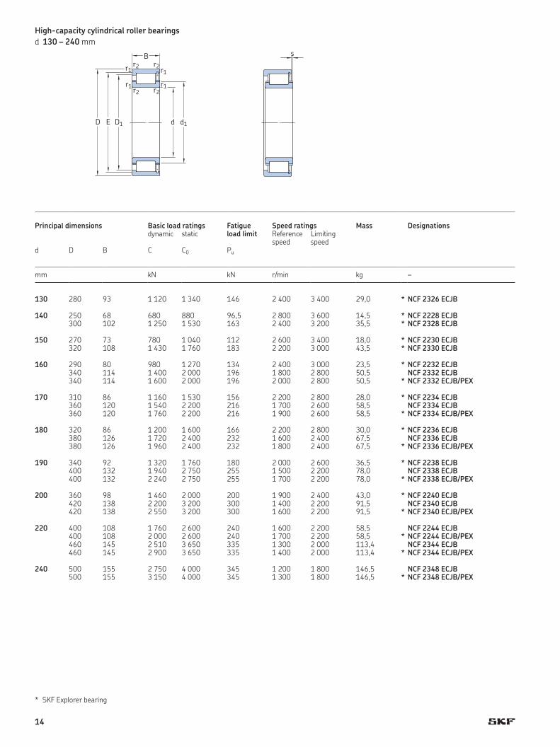
130 280 93 1 120 1 340 146 2 400 3 400 29,0 * NCF 2326 ECJB
140 250 68 680 880 96,5 2 800 3 600 14,5 * NCF 2228 ECJB300 102 1 250 1 530 163 2 400 3 200 35,5 * NCF 2328 ECJB
150 270 73 780 1 040 112 2 600 3 400 18,0 * NCF 2230 ECJB320 108 1 430 1 760 183 2 200 3 000 43,5 * NCF 2330 ECJB
160 290 80 980 1 270 134 2 400 3 000 23,5 * NCF 2232 ECJB340 114 1 400 2 000 196 1 800 2 800 50,5 NCF 2332 ECJB340 114 1 600 2 000 196 2 000 2 800 50,5 * NCF 2332 ECJB/PEX
170 310 86 1 160 1 530 156 2 200 2 800 28,0 * NCF 2234 ECJB360 120 1 540 2 200 216 1 700 2 600 58,5 NCF 2334 ECJB360 120 1 760 2 200 216 1 900 2 600 58,5 * NCF 2334 ECJB/PEX
180 320 86 1 200 1 600 166 2 200 2 800 30,0 * NCF 2236 ECJB380 126 1 720 2 400 232 1 600 2 400 67,5 NCF 2336 ECJB380 126 1 960 2 400 232 1 800 2 400 67,5 * NCF 2336 ECJB/PEX
190 340 92 1 320 1 760 180 2 000 2 600 36,5 * NCF 2238 ECJB400 132 1 940 2 750 255 1 500 2 200 78,0 NCF 2338 ECJB400 132 2 240 2 750 255 1 700 2 200 78,0 * NCF 2338 ECJB/PEX
200 360 98 1 460 2 000 200 1 900 2 400 43,0 * NCF 2240 ECJB420 138 2 200 3 200 300 1 400 2 200 91,5 NCF 2340 ECJB420 138 2 550 3 200 300 1 600 2 200 91,5 * NCF 2340 ECJB/PEX
220 400 108 1 760 2 600 240 1 600 2 200 58,5 NCF 2244 ECJB400 108 2 000 2 600 240 1 700 2 200 58,5 * NCF 2244 ECJB/PEX460 145 2 510 3 650 335 1 300 2 000 113,4 NCF 2344 ECJB460 145 2 900 3 650 335 1 400 2 000 113,4 * NCF 2344 ECJB/PEX
240 500 155 2 750 4 000 345 1 200 1 800 146,5 NCF 2348 ECJB500 155 3 150 4 000 345 1 300 1 800 146,5 * NCF 2348 ECJB/PEX
Principal dimensions Basic load ratings Fatigue load limit
Speed ratings Mass Designationsdynamic static Reference
speedLimiting speed
d D B C C0 Pu
mm kN kN r/min kg –
High-capacity cylindrical roller bearingsd 130 – 240 mm
SKF Explorer bearing*
14
Db
ra
Da da
ra
ra
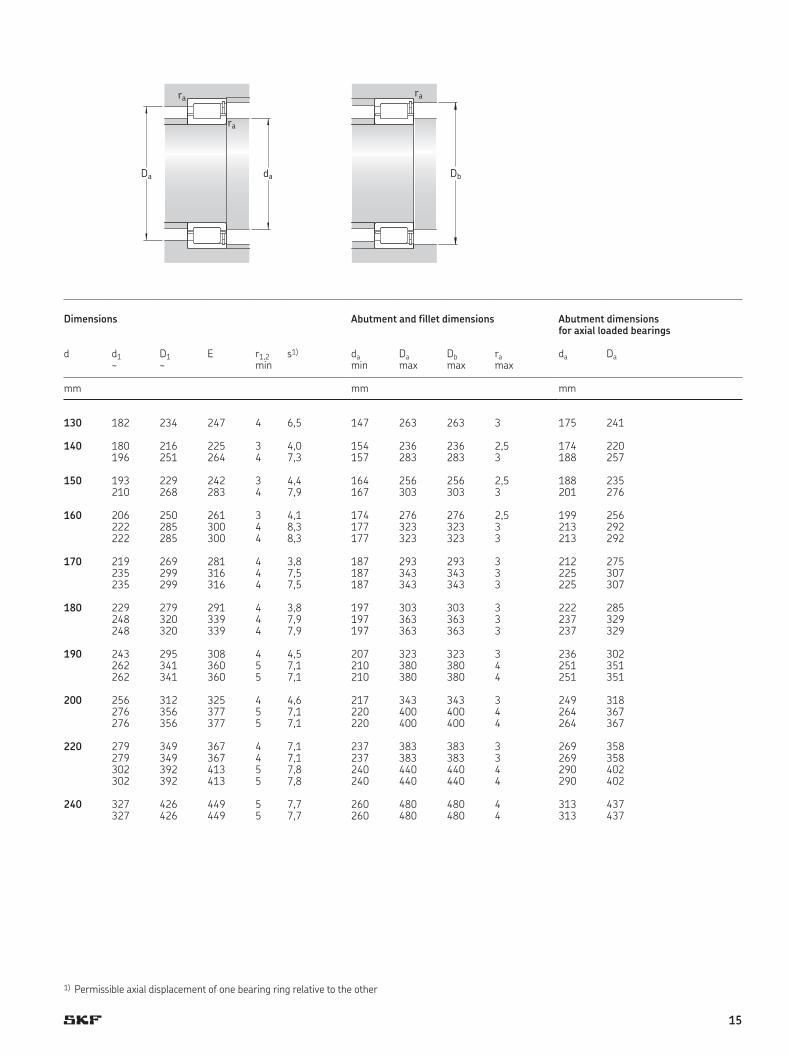
Dimensions Abutment and fillet dimensions Abutment dimensions for axial loaded bearings
d d1 D1 E r1,2 s1) da Da Db ra da Da~ ~ min min max max max
mm mm mm
130 182 234 247 4 6,5 147 263 263 3 175 241
140 180 216 225 3 4,0 154 236 236 2,5 174 220196 251 264 4 7,3 157 283 283 3 188 257
150 193 229 242 3 4,4 164 256 256 2,5 188 235210 268 283 4 7,9 167 303 303 3 201 276
160 206 250 261 3 4,1 174 276 276 2,5 199 256222 285 300 4 8,3 177 323 323 3 213 292222 285 300 4 8,3 177 323 323 3 213 292
170 219 269 281 4 3,8 187 293 293 3 212 275235 299 316 4 7,5 187 343 343 3 225 307235 299 316 4 7,5 187 343 343 3 225 307
180 229 279 291 4 3,8 197 303 303 3 222 285248 320 339 4 7,9 197 363 363 3 237 329248 320 339 4 7,9 197 363 363 3 237 329
190 243 295 308 4 4,5 207 323 323 3 236 302262 341 360 5 7,1 210 380 380 4 251 351262 341 360 5 7,1 210 380 380 4 251 351
200 256 312 325 4 4,6 217 343 343 3 249 318276 356 377 5 7,1 220 400 400 4 264 367276 356 377 5 7,1 220 400 400 4 264 367
220 279 349 367 4 7,1 237 383 383 3 269 358279 349 367 4 7,1 237 383 383 3 269 358302 392 413 5 7,8 240 440 440 4 290 402302 392 413 5 7,8 240 440 440 4 290 402
240 327 426 449 5 7,7 260 480 480 4 313 437327 426 449 5 7,7 260 480 480 4 313 437
1) Permissible axial displacement of one bearing ring relative to the other
15
Bearings and unitsSeals Lubrication
systems
Mechatronics Services
The Power of Knowledge Engineering
Drawing on five areas of competence and application-specific expertise amassed over more than 100 years, SKF brings innovative solutions to OEMs and production facilities in every major industry world-wide. These five competence areas include bearings and units, seals, lubrication systems, mechatronics (combining mechanics and electronics into intelligent systems), and a wide range of services, from 3-D computer modelling to advanced condition monitoring and reliability and asset management systems. A global presence provides SKF customers uniform quality standards and worldwide product availability.
® SKF and SKF EXPLORER are registered trademarks of the SKF Group.
© SKF Group 2010The contents of this publication are the copyright of the publisher and may not be reproduced (even extracts) unless prior written permission is granted. Every care has been taken to ensure the accuracy of the information contained in this publication but no liability can be accepted for any loss or damage whether direct, indirect or consequential arising out of the use of the information contained herein.
PUB BU/P2 06894 EN · March 2010
Printed in Sweden on environmentally friendly paper.
skf.com