Embed Size (px)
Citation preview

Slew Drive Manual
www.kinematicsmfg.com
Manual Revision :1609
2 | S l e w D r i v e M a n u a l
Facilities USA Kinematics Manufacturing
21410 N. 15th Lane, Suite 104
Phoenix, AZ 85027, USA
Telephone: +1.623.780.8944
Email: mailto:[email protected]
Web: www.kinematicsmfg.com CHINA Jiangyin Kinematics Manufacturing Co. Ltd.
Xiagang Industrial Park, Xiagang, Jiangyin, Jiangsu, P. R. China
Telephone: +86-(0)510 8696 3383
Email: [email protected]
Web: www.kinematicsmfg.com Europe/Middle East Neuchatel Kinematics Manufacturing Sarl
Rue De La Promenade-Noire 1
Neuenburg 2000
Neuchatel, Switzerland
Email: [email protected]
Web: www.kinematicsmfg.com
KMI accepts no liability for:
Non-compliance with Installation and Maintenance Instructions.
Failure to pass on content to third party.
Any omissions or errors in the document.
Notice: The following text includes special notices and procedures that shall be observed.
3 | S l e w D r i v e M a n u a l
Contents Facilities ........................................................................................................................................................................................................................ 2
Preface ........................................................................................................................................................................................................................... 4
Model Code ................................................................................................................................................................................................................. 5
Transport, Handling & Storage ............................................................................................................................................................................. 7
Installation ................................................................................................................................................................................................................... 8
Preparation ......................................................................................................................................................................................................................................................... 8
Cleaning .............................................................................................................................................................................................................................................................. 8
Permissible Flatness Deviation ..................................................................................................................................................................................................................... 9
Mounting Bolts ................................................................................................................................................................................................................................................ 10
Install the Slewing Drive ............................................................................................................................................................................................................................... 11
Determine Tilting Clearance ....................................................................................................................................................................................................................... 13
Primary Movers ....................................................................................................................................................................................................... 14
Electric motor .................................................................................................................................................................................................................................................. 14
Hall Encoder ..................................................................................................................................................................................................................................................... 15
Maintenance & Safety Checks ............................................................................................................................................................................ 16
Mounting Bolts ................................................................................................................................................................................................................................................ 16
Tilting Clearance Measuring tilting clearance on new product without rated load ....................................................................................................................... 17
Torsional Clearance ....................................................................................................................................................................................................................................... 19
Lubrication Instruction ................................................................................................................................................................................................................................. 20
Weather Protection ................................................................................................................................................................................................ 21
Paint spec .......................................................................................................................................................................................................................................................... 21
Grease Spec ...................................................................................................................................................................................................................................................... 22
Liquid Sealant .................................................................................................................................................................................................................................................. 24
Thread Lock Liquid ......................................................................................................................................................................................................................................... 24
Temperature Rating of Overall Drive ....................................................................................................................................................................................................... 25
Transport, packaging, and storage ................................................................................................................................................................... 25
Limited Warranty ..................................................................................................................................................................................................... 27
4 | S l e w D r i v e M a n u a l
Preface The following instructions give you the information you need to be able to correctly install and maintain a KMI slew
drive.
These instructions replace earlier versions.
All work steps listed here are to be executed by suitably qualified personnel.
Please do not hesitate to contact our Technical Department for any further assistance.
5 | S l e w D r i v e M a n u a l
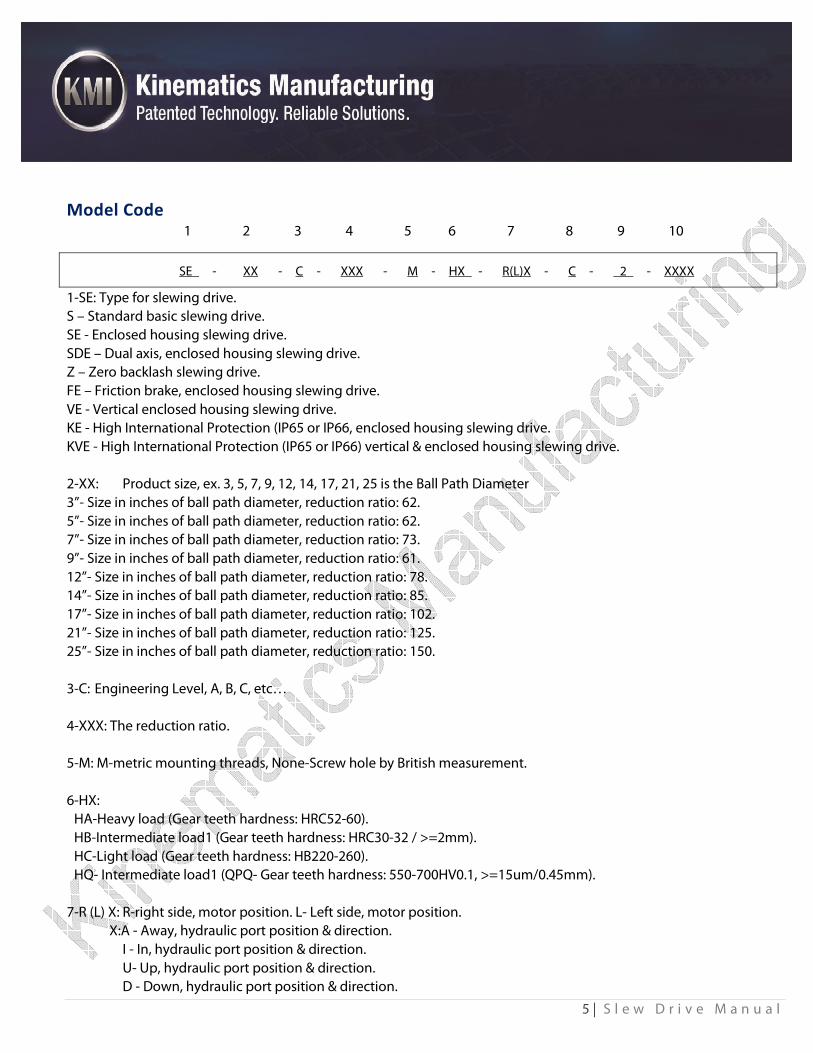
Model Code 1 2 3 4 5 6 7 8 9 10
SE - XX - C - XXX - M - HX - R(L)X - C - 2 - XXXX
1-SE: Type for slewing drive.
S – Standard basic slewing drive.
SE - Enclosed housing slewing drive.
SDE – Dual axis, enclosed housing slewing drive.
Z – Zero backlash slewing drive.
FE – Friction brake, enclosed housing slewing drive.
VE - Vertical enclosed housing slewing drive.
KE - High International Protection (IP65 or IP66, enclosed housing slewing drive.
KVE - High International Protection (IP65 or IP66) vertical & enclosed housing slewing drive.
2-XX: Product size, ex. 3, 5, 7, 9, 12, 14, 17, 21, 25 is the Ball Path Diameter
3”- Size in inches of ball path diameter, reduction ratio: 62.
5”- Size in inches of ball path diameter, reduction ratio: 62.
7”- Size in inches of ball path diameter, reduction ratio: 73.
9”- Size in inches of ball path diameter, reduction ratio: 61.
12”- Size in inches of ball path diameter, reduction ratio: 78.
14”- Size in inches of ball path diameter, reduction ratio: 85.
17”- Size in inches of ball path diameter, reduction ratio: 102.
21”- Size in inches of ball path diameter, reduction ratio: 125.
25”- Size in inches of ball path diameter, reduction ratio: 150.
3-C: Engineering Level, A, B, C, etc…
4-XXX: The reduction ratio.
5-M: M-metric mounting threads, None-Screw hole by British measurement.
6-HX:
HA-Heavy load (Gear teeth hardness: HRC52-60).
HB-Intermediate load1 (Gear teeth hardness: HRC30-32 / >=2mm).
HC-Light load (Gear teeth hardness: HB220-260).
HQ- Intermediate load1 (QPQ- Gear teeth hardness: 550-700HV0.1, >=15um/0.45mm).
7-R (L) X: R-right side, motor position. L- Left side, motor position.
X:A - Away, hydraulic port position & direction.
I - In, hydraulic port position & direction.
U- Up, hydraulic port position & direction.
D - Down, hydraulic port position & direction.
6 | S l e w D r i v e M a n u a l
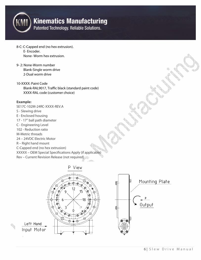
8-C: C-Capped end (no hex extrusion).
E- Encoder.
None- Worm hex extrusion.
9- 2: None-Worm number
Blank-Single worm drive
2-Dual worm drive
10-XXXX: Paint Code
Blank-RAL9017, Traffic black (standard paint code)
XXXX-RAL code (customer choice)
Example:
SE17C-102M-24RC-XXXX-REV.A
S - Slewing drive
E - Enclosed housing
17 - 17'' ball path diameter
C - Engineering Level
102 - Reduction ratio
M-Metric threads
24 – 24VDC Electric Motor
R – Right hand mount
C-Capped end (no hex extrusion)
XXXXX – OEM Special Specifications Apply (if applicable)
Rev – Current Revision Release (not required)
7 | S l e w D r i v e M a n u a l
Transport, Handling & Storage Transport only in horizontal position, impacts should be avoided.
Wear work gloves and be careful when handling the slewing drives.
Use the holes of the rings in the slewing drives to fix bolts for safe hoisting, handling and placement.
Store only in a horizontal position and in closed rooms, keep it away from getting wet, the surface corrosion
protection of exposed mating surfaces lasts approximately 1 month in closed packaging. Longer period storage
requires special protective measures.
8 | S l e w D r i v e M a n u a l
Installation
Preparation
Check the slewing drive for physical damage.
Clean the slewing drive and the mounting structure, see Cleaning.
Remove extraneous materials from supporting surfaces.
Cleaning
Clean corrosion protection coating from supporting surfaces of the slewing drive, follow the instructions below:
Clean the exterior of the mounting surfaces using cold solvent (e.g. diesel oil) that will not damage the rubber seals.
Applicable provisions for cleaning media are observed (e.g. manufacturer provisions, protection of workers,
environment protection).
9 | S l e w D r i v e M a n u a l
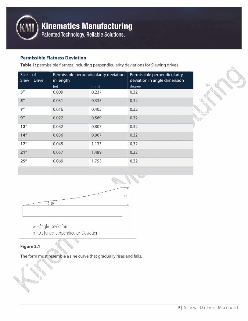
Permissible Flatness Deviation
Table 1: permissible flatness including perpendicularity deviations for Slewing drives
Size of
Slew Drive
Permissible perpendicularity deviation
in length
Permissible perpendicularity
deviation in angle dimension
[in] [mm] degree
3” 0.009 0.237 0.32
5” 0.031 0.335 0.32
7” 0.016 0.405 0.32
9” 0.022 0.569 0.32
12” 0.032 0.807 0.32
14” 0.036 0.907 0.32
17” 0.045 1.133 0.32
21” 0.057 1.489 0.32
25” 0.069 1.753 0.32
Figure 2.1
The form must resemble a sine curve that gradually rises and falls.
10 | S l e w D r i v e M a n u a l
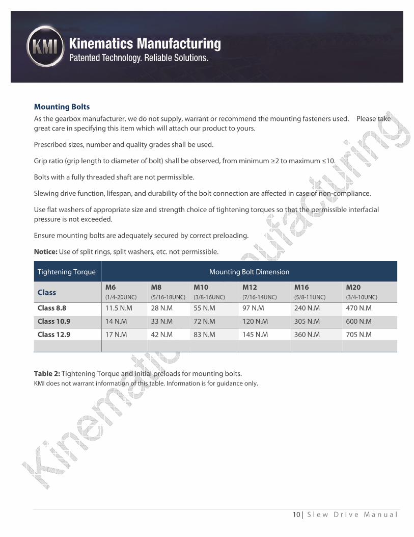
Mounting Bolts
As the gearbox manufacturer, we do not supply, warrant or recommend the mounting fasteners used. Please take
great care in specifying this item which will attach our product to yours.
Prescribed sizes, number and quality grades shall be used.
Grip ratio (grip length to diameter of bolt) shall be observed, from minimum ≥2 to maximum ≤10.
Bolts with a fully threaded shaft are not permissible.
Slewing drive function, lifespan, and durability of the bolt connection are affected in case of non-compliance.
Use flat washers of appropriate size and strength choice of tightening torques so that the permissible interfacial
pressure is not exceeded.
Ensure mounting bolts are adequately secured by correct preloading.
Notice: Use of split rings, split washers, etc. not permissible.
Table 2: Tightening Torque and initial preloads for mounting bolts.
KMI does not warrant information of this table. Information is for guidance only.
Tightening Torque Mounting Bolt Dimension
Class M6
(1/4-20UNC)
M8
(5/16-18UNC)
M10
(3/8-16UNC)
M12
(7/16-14UNC)
M16
(5/8-11UNC)
M20
(3/4-10UNC)
Class 8.8 11.5 N.M 28 N.M 55 N.M 97 N.M 240 N.M 470 N.M
Class 10.9 14 N.M 33 N.M 72 N.M 120 N.M 305 N.M 600 N.M
Class 12.9 17 N.M 42 N.M 83 N.M 145 N.M 360 N.M 705 N.M

11 | S l e w D r i v e M a n u a l
Installing the Slewing Drive
Clean the mounting structure, e.g. from welding, galvanizing, residues, dirt, etc.
Lift the slewing drive with eye bolts.
The slewing drive shall be mounted in unloaded condition.
Remove the shipping bolts before setting on the final mounting structure.
The following procedure (Figure 2.2) shall be followed in order to avoid deviations between bolt tightening forces.
Apply thread lock liquid to threads.
Brand:
Type: TS242Threadlocking adhesive
Note: General purpose, chemotropic, viscosity. For locking and sealing M6-M20 threads
Parts can be separated using hand tools, controlled lubricity, can attain accurate clamp loads.
Color: Blue
Usage:
Shake thoroughly before use
Clean and dry parts with TS755 cleanser
Lay thread lock liquid on thread gap requesting fitting parts fully.
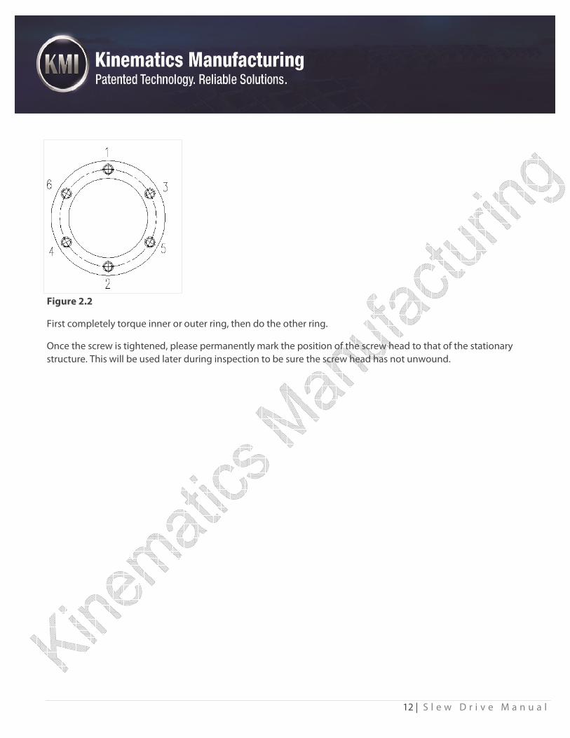
Preload the bolts crosswise. See the general pattern in sketch below of how bolts get torque in crosswise sequence.
Start with either inner or outer ring. Do the crosswise torqueing of all bolts to 30% of tightening torque. Then repeat
crosswise torque to 80% of tightening torque. Finally, crosswise torque to 100% of the tightening torque.
12 | S l e w D r i v e M a n u a l
Figure 2.2
First completely torque inner or outer ring, then do the other ring.
Once the screw is tightened, please permanently mark the position of the screw head to that of the stationary
structure. This will be used later during inspection to be sure the screw head has not unwound.
13 | S l e w D r i v e M a n u a l
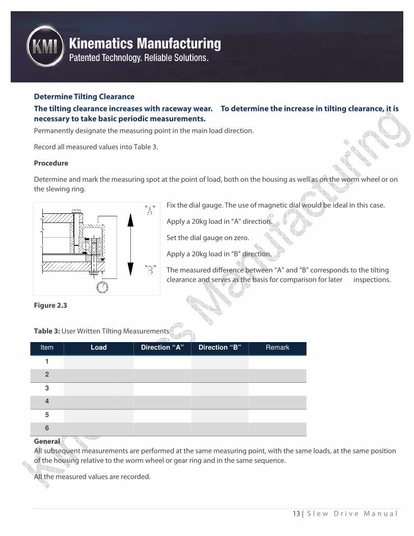
Determine Tilting Clearance
The tilting clearance increases with raceway wear. To determine the increase in tilting clearance, it is
necessary to take basic periodic measurements.
Permanently designate the measuring point in the main load direction.
Record all measured values into Table 3.
Procedure
Determine and mark the measuring spot at the point of load, both on the housing as well as on the worm wheel or on
the slewing ring.
Fix the dial gauge. The use of magnetic dial would be ideal in this case.
Apply a 20kg load in “A” direction.
Set the dial gauge on zero.
Apply a 20kg load in “B” direction.
The measured difference between “A” and “B” corresponds to the tilting
clearance and serves as the basis for comparison for later inspections.
Figure 2.3
Table 3: User Written Tilting Measurements
Item Load Direction “A” Direction “B” Remark
1
2
3
4
5
6
General
All subsequent measurements are performed at the same measuring point, with the same loads, at the same position
of the housing relative to the worm wheel or gear ring and in the same sequence.
All the measured values are recorded.
14 | S l e w D r i v e M a n u a l
Primary Movers
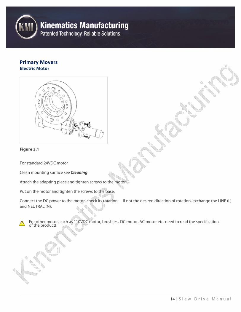
Electric Motor
Figure 3.1
For standard 24VDC motor
Clean mounting surface see Cleaning
Attach the adapting piece and tighten screws to the motor;
Put on the motor and tighten the screws to the base;
Connect the DC power to the motor, check its rotation. If not the desired direction of rotation, exchange the LINE (L)
and NEUTRAL (N).
For other motor, such as 110VDC motor, brushless DC motor, AC motor etc. need to read the specification of the product!
15 | S l e w D r i v e M a n u a l
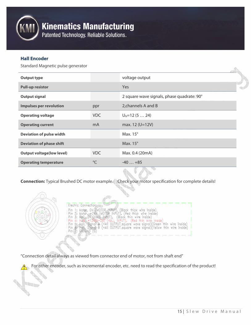
Hall Encoder
Standard Magnetic pulse generator
Output type voltage output
Pull-up resistor Yes
Output signal 2 square wave signals, phase quadrate: 90°
Impulses per revolution ppr 2,channels A and B
Operating voltage VDC UN=12 (5 … 24)
Operating current mA max. 12 (U=12V)
Deviation of pulse width Max. 15°
Deviation of phase shift Max. 15°
Output voltage(low level) VDC Max. 0.4 (20mA)
Operating temperature ℃ -40 … +85
Connection: Typical Brushed DC motor example. Check your motor specification for complete details!
“Connection detail always as viewed from connector end of motor, not from shaft end”
For other encoder, such as incremental encoder, etc. need to read the specification of the product!
16 | S l e w D r i v e M a n u a l
Maintenance & Safety Checks
Mounting Bolts
To compensate for possible settling, it is necessary to retighten the bolts to the prescribed torque .This shall be done
after no more than 100 hours of operation and without external load applied to the bolt connection. This inspection
shall be repeated annually.
The inspection frequency may be reduced under special operating conditions. In case of loose bolts, replace all bolts
and washers with new ones.
KMI does not supply or warrant any fasteners for attaching the slew drive to the customer’s equipment. The few
large diameter cap screws shipped in the new slewing drives are for shipping purposes only. These are very low
grade fasteners and should never be reused in the final installation of the slew drive.
17 | S l e w D r i v e M a n u a l
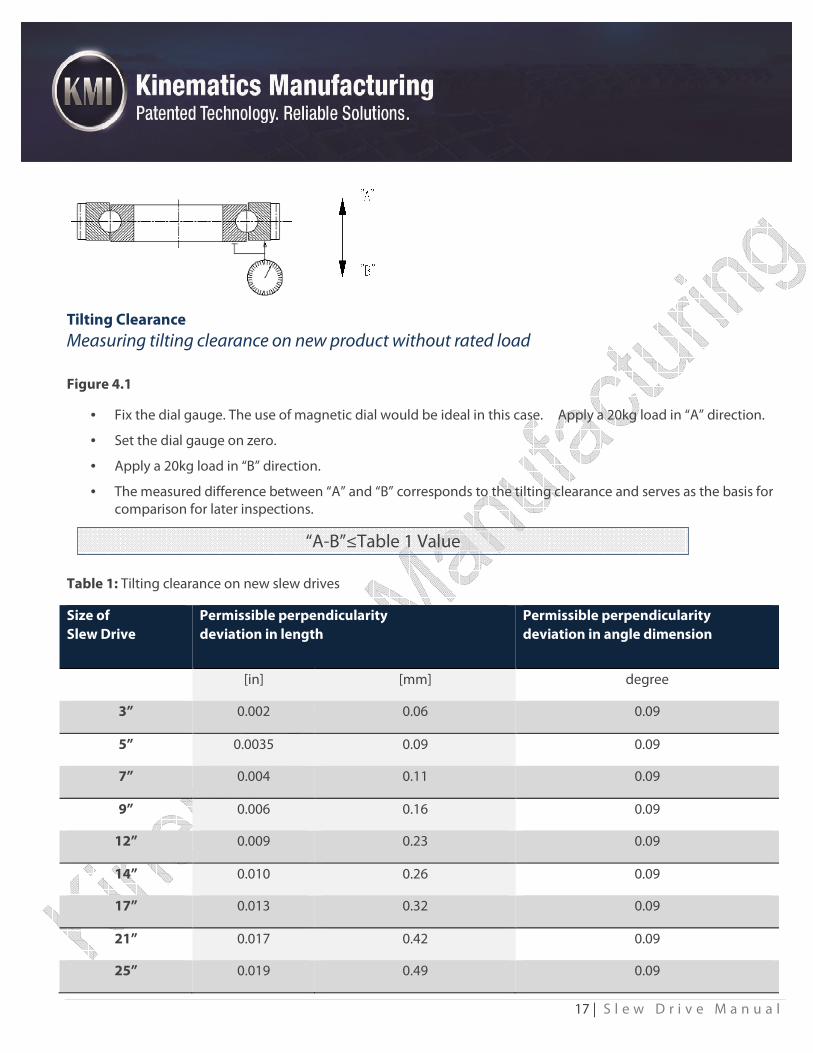
Tilting Clearance
Measuring tilting clearance on new product without rated load
Figure 4.1
• Fix the dial gauge. The use of magnetic dial would be ideal in this case. Apply a 20kg load in “A” direction.
• Set the dial gauge on zero.
• Apply a 20kg load in “B” direction.
• The measured difference between “A” and “B” corresponds to the tilting clearance and serves as the basis for comparison for later inspections.
Table 1: Tilting clearance on new slew drives
Size of
Slew Drive
Permissible perpendicularity
deviation in length
Permissible perpendicularity
deviation in angle dimension
[in] [mm] degree
3” 0.002 0.06 0.09
5” 0.0035 0.09 0.09
7” 0.004 0.11 0.09
9” 0.006 0.16 0.09
12” 0.009 0.23 0.09
14” 0.010 0.26 0.09
17” 0.013 0.32 0.09
21” 0.017 0.42 0.09
25” 0.019 0.49 0.09
“A-B”≤Table 1 Value
18 | S l e w D r i v e M a n u a l
Measuring tilting clearance on new product under rated load
• Install slew drive into customer specific equipment using customer’s standard load, as long as the load falls
within maximum guideline ratings of the KMI slewing drive.
• Take a measurement using the same instruction of 4.2.1 Record this value as the equipment’s starting
raceway tilting clearance value.
• Raceway wear leads to increased tilting clearance.
• Check the increase in tilting clearance δk directly on a slewing drive.
• The value (m1) determined after installation of the slewing drive is considered as the basic value and is
deducted from the latest inspection value (mx). The difference between mx and m1 may not exceed 0.8 mm
(0.0315in) during the life of the drive. If this value is exceeded then the drive is worn out.
• Increase in tilting clearance is to be converted proportionally for each measurement (after the installation
measurement) and compared with δk permissible.
• Reduce the inspection interval to 200 operating hours if the measured increase in tilting clearance amounts to
approx. 75% of the maximum permissible increase in tilting clearance.
• Reduce the inspection interval once again after further increase in tilting clearance (to 50-100 operating
hours).
• Replace the slewing drive if the maximum permissible increase in tilting clearance is reached.
δk = mx-m1 ≤δT perm
δT perm= 0.8mm (0.0315in)
19 | S l e w D r i v e M a n u a l
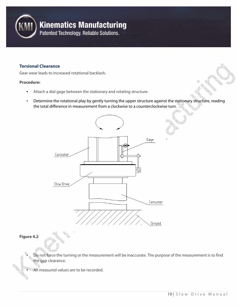
Torsional Clearance
Gear wear leads to increased rotational backlash.
Procedure:
• Attach a dial gage between the stationary and rotating structure.
• Determine the rotational play by gently turning the upper structure against the stationary structure, reading
the total difference in measurement from a clockwise to a counterclockwise turn.
Figure 4.2
• Do not force the turning or the measurement will be inaccurate. The purpose of the measurement is to find
the gap clearance.
• All measured values are to be recorded.
20 | S l e w D r i v e M a n u a l
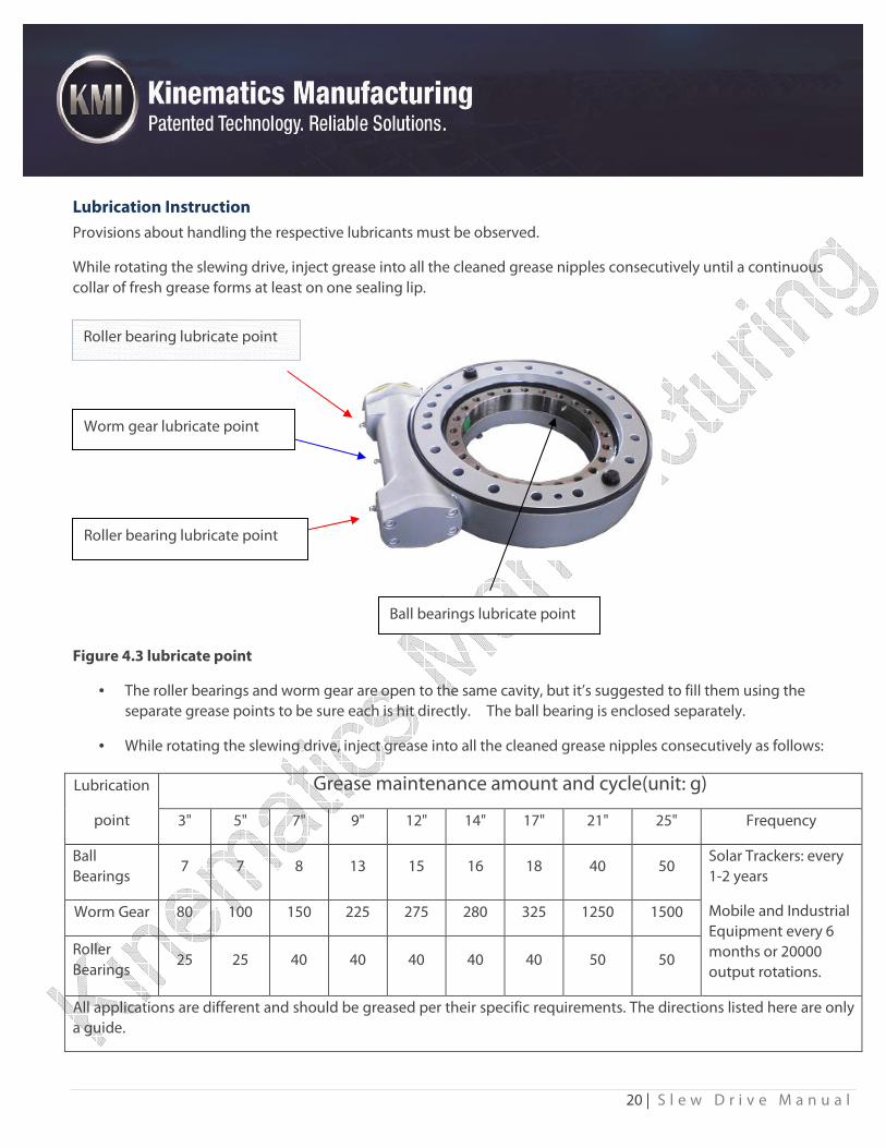
Lubrication Instruction
Provisions about handling the respective lubricants must be observed.
While rotating the slewing drive, inject grease into all the cleaned grease nipples consecutively until a continuous
collar of fresh grease forms at least on one sealing lip.
Figure 4.3 lubricate point
• The roller bearings and worm gear are open to the same cavity, but it’s suggested to fill them using the
separate grease points to be sure each is hit directly. The ball bearing is enclosed separately.
• While rotating the slewing drive, inject grease into all the cleaned grease nipples consecutively as follows:
Lubrication
point
Grease maintenance amount and cycle(unit: g)
3" 5" 7" 9" 12" 14" 17" 21" 25" Frequency
Ball
Bearings 7 7 8 13 15 16 18 40 50
Solar Trackers: every
1-2 years
Mobile and Industrial
Equipment every 6
months or 20000
output rotations.
Worm Gear 80 100 150 225 275 280 325 1250 1500
Roller
Bearings 25 25 40 40 40 40 40 50 50
All applications are different and should be greased per their specific requirements. The directions listed here are only
a guide.
Worm gear lubricate point
Roller bearing lubricate point
Ball bearings lubricate point
Roller bearing lubricate point
21 | S l e w D r i v e M a n u a l
Weather Protection
Paint spec
Epoxy Epicon Zinc HB-2
KMI drives are coated with a special two part epoxy coating in KMI’s automated painting line to give the drive
excellent heat and weather protection.
Epoxy
Brand:
EPICON ZINC HB-2
EPICON ZINC HB-2 is a high-build type epoxy zinc rich paint based on a combination of epoxy resin and polyamide
resin pigmented with metallic zinc power.
It has the following advantages:
• Long term rust-preventing property;
• Excellent physical properties such as toughness, impact and abrasion resistance;
• Extreme resistance to seawater, rain, heat, oil, oxidation and sunlight.
Recommended Use:
• As a primer for protection of blast-cleaned steel plates (ISO 8501-1 1988 Sa 2.5)
• Volume Solid: 52±2%
• Dry Film Thickness: 2.0-3.0 mils; 80-100 μm;
• Method of Application: Airless spray
• Thinner: EPOXY THINNER A
• Temperature Rating: 80C
22 | S l e w D r i v e M a n u a l
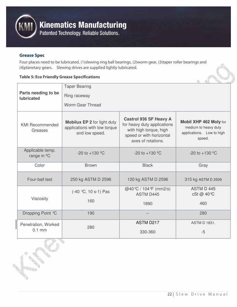
Grease Spec
Four places need to be lubricated, (1)slewing ring ball bearings, (2)worm gear, (3)taper roller bearings and
(4)planetary gears. Slewing drives are supplied lightly lubricated.
Table 5: Eco Friendly Grease Specifications
Parts needing to be
lubricated
Taper Bearing
Ring raceway
Worm Gear Thread
KMI Recommended
Greases
Mobilux EP 2 for light duty
applications with low torque
and low speed.
Castrol 936 SF Heavy A
for heavy duty applications
with high torque, high
speed or with horizontal
axes of rotations.
Mobil XHP 462 Moly for
medium to heavy duty
applications. Low to high
speed.
Applicable temp.
range in ºC -20 to +130 ºC -20 to +130 ºC -20 to +130 ºC
Color Brown Black Gray
Four-ball test 250 kg ASTM D 2596 120 kg ASTM D 2596 315 kg ASTM D 2509
Viscosity
(-40 °C, 10 s-1) Pas
160
@40°C / 104°F (mm2/s)
ASTM D445
1890
ASTM D 445
cSt @ 40°C
460
Dropping Point °C 190 -- 280
Penetration, Worked
0.1 mm 280
ASTM D217
330-360
ASTM D 1831,
-5
23 | S l e w D r i v e M a n u a l
Mobilux EP 2 is a lithium hydroxystearate based grease. It’s formulated to provide extra protection against
wear, rust and water. It is applied in heavy-duty application where high unit pressures are present. It
provides excellent protection against rust and corrosion.
The grease helps to provide reduced wear under heavy load and vibration, protection against rust in the
presence of water, extended bearing life in wet environments.
It meets or exceeds DIN 51825 (2004-06)
Castrol Molub-Alloy 936® SF Heavy is a uniquely compounded open gear lubricant developed specifically for
use on heavy-duty equipment in mining and industrial service. It forms a tough lubricating film on the friction
surfaces which is resistant to pressure and shock loads as well as unfavorable ambient conditions.
It meets or exceeds DIN 51502.
24 | S l e w D r i v e M a n u a l
Liquid Sealant
Product Description
LOCTITE® 510™ provides the following product characteristics:
Technology Acrylic
Chemical Type Dimethacrylate ester
Appearance (uncured) Opaque pink paste LMS
Components One component - requires no mixing
Viscosity High
Cure Anaerobic
Application Gaskets and Sealing
Strength Medium
LOCTITE® 510™ cures when confined in the absence of air between close fitting metal surfaces. This product is a
general gasket product suitable for hand dispensing or screen printing.
Thread Lock Liquid
Tighten thread locking adhesives
Tighten thread locking adhesives are widely used for sealing, locking and corrosion resistance of threaded fasteners in
various environments, can replace spring washers, pins and other traditional mechanical locking methods.
TS242 Thread locking adhesive TS242
Medium strength
• General purpose, chemotropic viscosity, For locking and sealing M6-M20 threads.
• Parts can be separated with hand tools, controlled lubricity, can attain accurate clamp loads.
• Technical Specification
Color:Blue
Viscosity:1200/6000 mPa.s
Prevail Torque:4.8 Nm
Break Torque:12 Nm
Gap Fill:0.13 mm
25 | S l e w D r i v e M a n u a l
Temperature Rating of Overall Drive
Overall Slew Drive Temperature Rating: -20°C to +80°C
Transport, packaging, and storage
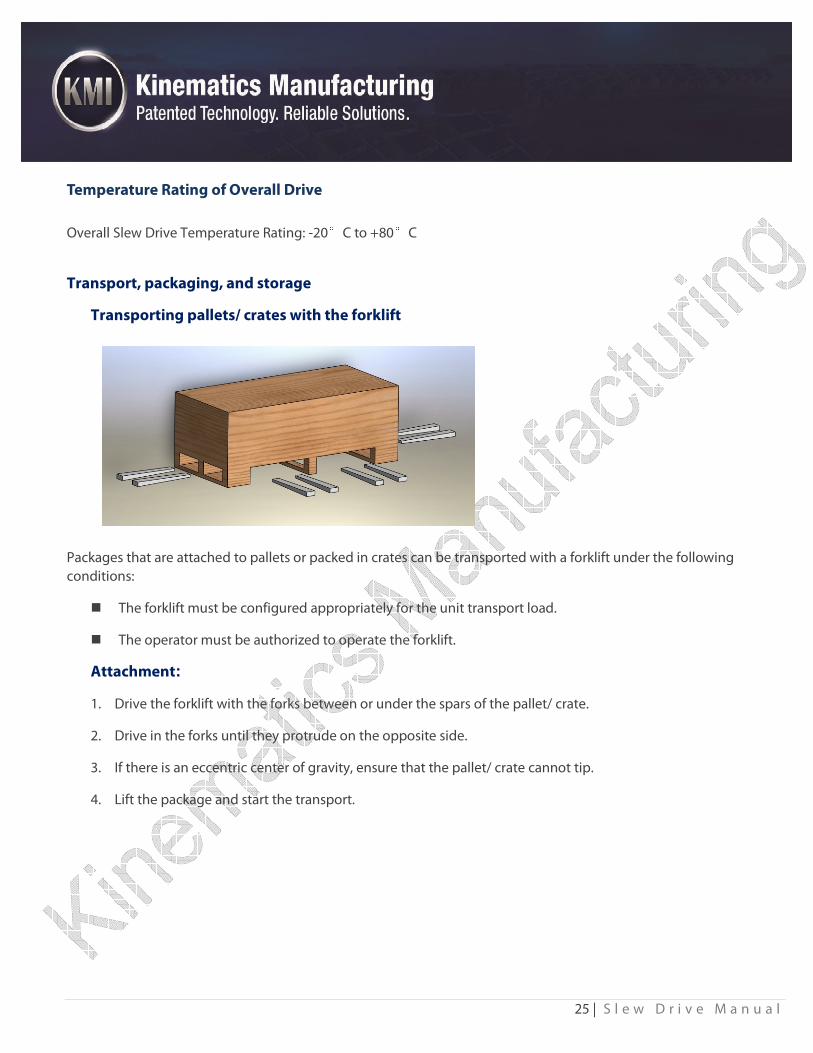
Transporting pallets/ crates with the forklift
Packages that are attached to pallets or packed in crates can be transported with a forklift under the following
conditions:
� The forklift must be configured appropriately for the unit transport load.
� The operator must be authorized to operate the forklift.
Attachment:
1. Drive the forklift with the forks between or under the spars of the pallet/ crate.
2. Drive in the forks until they protrude on the opposite side.
3. If there is an eccentric center of gravity, ensure that the pallet/ crate cannot tip.
4. Lift the package and start the transport.
26 | S l e w D r i v e M a n u a l
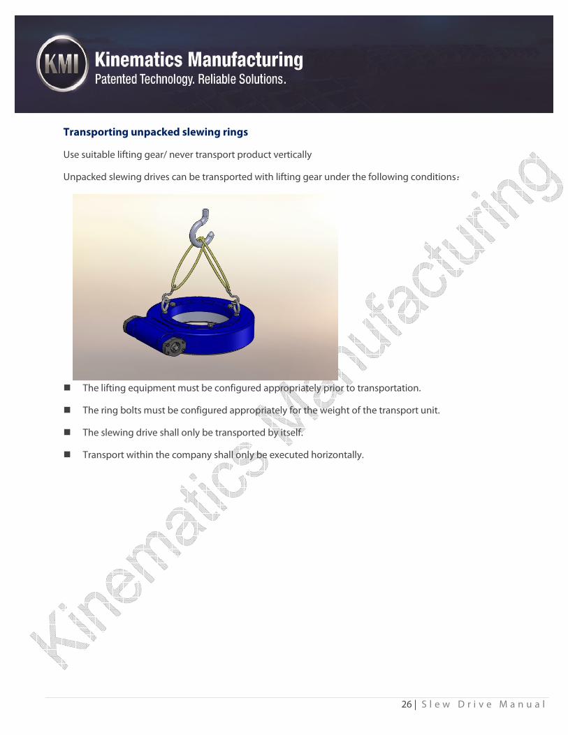
Transporting unpacked slewing rings
Use suitable lifting gear/ never transport product vertically
Unpacked slewing drives can be transported with lifting gear under the following conditions:
� The lifting equipment must be configured appropriately prior to transportation.
� The ring bolts must be configured appropriately for the weight of the transport unit.
� The slewing drive shall only be transported by itself.
� Transport within the company shall only be executed horizontally.
27 | S l e w D r i v e M a n u a l
Limited Warranty
1.PURPOSE.
This limited warranty to Buyer, is to provide for repair or replacement of equipment that Seller does not correctly
manufacture. The equipment must be operated within the design specifications. The limited warranty does not cover
normal wear and tear, nor does it cover any normal deterioration.
2. LIMITED WARRANTY.
Seller guarantees that the equipment when in good repair properly adjusted and in the hands of a competent
operator is capable of performing as specified. Seller further provides the equipment to be free from defective
material and workmanship defects and agrees to furnish free of charge any part or parts necessary to make good any
defect directly traceable to a fault in material or workmanship of Seller provided that the claim for any such defect is
made within one (1) year after Seller's original invoice and provided the defective part or parts are promptly returned
to Seller's factory freight prepaid by Buyer. The charge will be prorated and will be a linear proportion of the original
charge to the amount of time remaining on the warranty. Personnel will be provided to do the repairs at an additional
charge. The decision as to replacement or repair of the equipment shall be solely that of Seller.
The Seller provides precision mechanical equipment that deteriorates every time it is used and this limited warranty
does not cover the wear and tear on products' or electric motors/components supplied by third pay vendors. Any
deterioration in performance resulting from the wear and tear on the equipment is not covered by this warranty.
Likewise any misuse or use of the equipment outside the design scope of the equipment resulting in damage or failed
performance is not a warranty issue
3. DAMAGES LIMITATION.
Seller’s liability on any claim for loss or damage arising out of this Warranty or from the performance or breach
connected with the supplying of any equipment, or the sale, resale, operation or use of such equipment, whether
based on contract, warranty, tort(including negligence) or other grounds, shall not exceed the original purchase price
of the equipment. Seller shall not in any event be liable for any claim, whether breach of contract, warranty, tort
(including negligence) or other grounds for incidental, special or consequential damages including, but not limited to
loss of profits or revenue, loss of use of the equipment or any associated product, cost of capital, cost of substitute
products, facilities or services downtime, cost or claims of customers of Buyer for such damage.
4. SYSTEMS AND OTHER EQUIPMENT.
If Seller is furnishing equipment to Buyer that is part of a larger or interconnected system no guarantee is made as to
the interaction of the components. Should Seller offer Buyer advice or other assistance which concerns the
interconnection of any equipment, or any system or equipment in which Sellers equipment may be installed, and
other equipment outside the scope of the equipment supplied by Seller, such advice or assistance will not subject
Seller to any liability of any kind.
28 | S l e w D r i v e M a n u a l
5. DISCLAIMER.
Components and accessories in Seller's final assembly but not of Seller's manufacture are warranted only to the extent
that they are warranted by the original Manufacturer. There are no other warranties, express or implied, either for
merchantability or of fitness for a particular purpose. Buyer agrees that there have been no representations upon
which Buyer rely other than those set forth in this Warranty. Unless specifically agreed in writing by an authorized
representative of Seller, equipment sold is not intended fro use where failure of a single component could cause
substantial harm to persons or property. If so used, Seller disclaims all liability. To the extent allowed by law, Seller
specifically excludes and disclaims any and all implied warranties, including, without limitation, any implied
warranties of merchantability and any implied warranties of fitness for a particular purpose. This Warranty does not
cover damage caused during shipment, from accident, misuse, abuse, neglect, unauthorized equipment modification,
failure to follow the operation instructions outlined in the owner’s manual, failure to perform routine maintenance,
and operation in excess of tolerances.
6. CHANGES TO EQUIPMENT.
It is further understood that any change to the equipment is done at the Buyers risk and Seller only provides a
guarantee on equipment as it has been delivered and used in the proper manner. Any change to the construction,
machining or any other aspect of the equipment will void any guarantee by the Seller and any not approved use or
misuse of the equipment will void the Warranty.
7. SELLER’S OPTION.
Buyer agrees that the sole liability of Seller by virtue of any limited warranty made by Seller is to make the equipment
fulfill the limited warranty. No limited warranty made by Seller shall be binding upon Seller after one (1) year from the
date of the original invoice of the equipment and no liability for any special indirect or consequential damages of any
nature is assumed by or shall be imposed by Seller based upon its undertakings herein.
8. INSTALLATION.
The equipment is a precision device and proper installation is a must. Should the equipment not be properly installed,
this Warranty is void. If the equipment is not installed by Buyer, it should be done by properly trained installers. The
equipment must be maintained as required in the installation instructions. The equipment must be maintained as
stated in the manuals. Damage caused by disasters such as fire, flood, lightening, or improper electric current or
power surges are not covered by this Warranty.
9. EXTRAORDINARY EVENTS.
Seller shall not be liable for the delay, non-delivery or default in shipment due to labor disputes, transportation
shortage, delays in receipt of material, priorities, fires, accidents and all other causes because of Force Majeure,
affecting Seller and/or its suppliers.
![KMI Hellstrahler Bro - GoGaS · KMI Hellstrahler KMI 6 KMI 12 KMI 18 KMI 24 KMI 36 Nennwärmebelastung [kW] min 3¹ 6 9 12 18 max 6¹ 12 18 24 36 Seasonal Efficiency [%] einstufig](https://img.pdfslide.net/doc/110x75/5f07465e7e708231d41c2d4e/kmi-hellstrahler-bro-gogas-kmi-hellstrahler-kmi-6-kmi-12-kmi-18-kmi-24-kmi-36.jpg)