Embed Size (px)
Citation preview
FM 5-410
CHAPTER 10
Slope Stabilization
This chapter pertains to the design of earthslopes as it relates to road construction. Itparticularly concerns slope stability andwhich slopes should be used under averageconditions in cuts and embankments. Someof the subjects covered are geologic featuresthat affect slope stability, soil mechanics, in-dicators of unstable slopes, types of slopefailures, and slope stabilization.
Road failures can exert a tremendous im-pact on mission success. It is vital thatpersonnel engaged in road-building activitiesbe aware of the basic principles of slopestability. They must understand how theseprinciples are applied to construct stableroads through various geologic materialswith specific conditions of slope and soil.
Basic slope stability is illustrated by adescription of the balance of forces that existin undisturbed slopes, how these forceschange as loads are applied, and howgroundwater affects slope stability andcauses road failure.
GEOLOGIC FEATURESThere are certain geologic features that
have a profound effect on slope stability andthat can consequently affect road construc-tion in an area. Many of these geologicfeatures can be observed in the field and mayalso be identified on topographic maps andaerial photographs. In some cases, thepresence of these features may be located bycomparing geologic and topographic maps.
The following paragraphs describe geologicfeatures that have a significant effect on slopestability and the techniques that may be usedto identify them:
FaultsThe geologic uplift that accompanies moun-
tain building is evident in the mountainousregions throughout the world. Stresses builtup in layers of rock by the warping that ac-companies uplift is usually relieved byfracturing. These fractures may extend forgreat distances both laterally and verticallyand are known as faults. Often the materialon one side of the fault is displaced verticallyrelative to the other side; sometimes igneousmaterial or serpentine may be intruded intofaults. Faults are the focal point for stressrelief and for intrusions of igneous rock andserpentine; therefore, fault zones usually con-tain rock that is fractured, crushed, or partlymetamorphosed. It is extremely important torecognize that fault zones are zones ofgeologic weakness and, as such, are critical inroad location. Faults often leave topographicclues to their location. An effort should bemade to identify any faults in the vicinity of aproposed road location.
The location of these fault zones is estab-lished by looking for—
Saddles, or low sections in ridges, thatare aligned in the same general di-rection from one drainage to another.
Streams that appear to deviate fromthe general direction of the nearbystreams.
Slope Stabilization 10-1
FM 5-410
Notice that the proposed locations of the faultzones on the topographic map follow saddlesand drainages in reasonably straight lines.
Aerial photographs should be carefully ex-amined for possible fault zones when neithergeologic maps nor topographic maps offer anyclues. An important feature of a fault zoneslide that may be detected from aerial photog-raphy is the slick, shiny surface caused by theintense heat developed by friction on slidingsurfaces within the fault zone.
Field personnel should be alert for on-the-ground evidence of faulting when neithergeologic maps nor topographic maps providedefinite clues to the location of faults.
Bedding Plane SlopeThere are many locations where sedi-
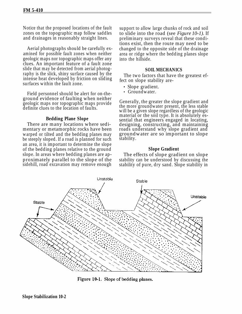
mentary or metamorphic rocks have beenwarped or tilted and the bedding planes maybe steeply sloped. If a road is planned for suchan area, it is important to determine the slopeof the bedding planes relative to the groundslope. In areas where bedding planes are ap-proximately parallel to the slope of thesidehill, road excavation may remove enough
support to allow large chunks of rock and soilto slide into the road (see Figure 10-1). Ifpreliminary surveys reveal that these condi-tions exist, then the route may need to bechanged to the opposite side of the drainagearea or ridge where the bedding planes slopeinto the hillside.
SOIL MECHANICSThe two factors that have the greatest ef-
fect on slope stability are-Slope gradient.Groundwater.
Generally, the greater the slope gradient andthe more groundwater present, the less stablewill be a given slope regardless of the geologicmaterial or the soil type. It is absolutely es-sential that engineers engaged in locating,designing, constructing, and maintainingroads understand why slope gradient andgroundwater are so important to slopestability.
Slope GradientThe effects of slope gradient on slope
stability can be understood by discussing thestability of pure, dry sand. Slope stability in
Slope Stabilization 10-2
FM 5-410
sand depends entirely on frictional resistanceto sliding. Frictional resistance to sliding, inturn, depends on—
The slope gradient that affects theportion of the weight of an object thatrests on the surface.
The coefficient of friction.
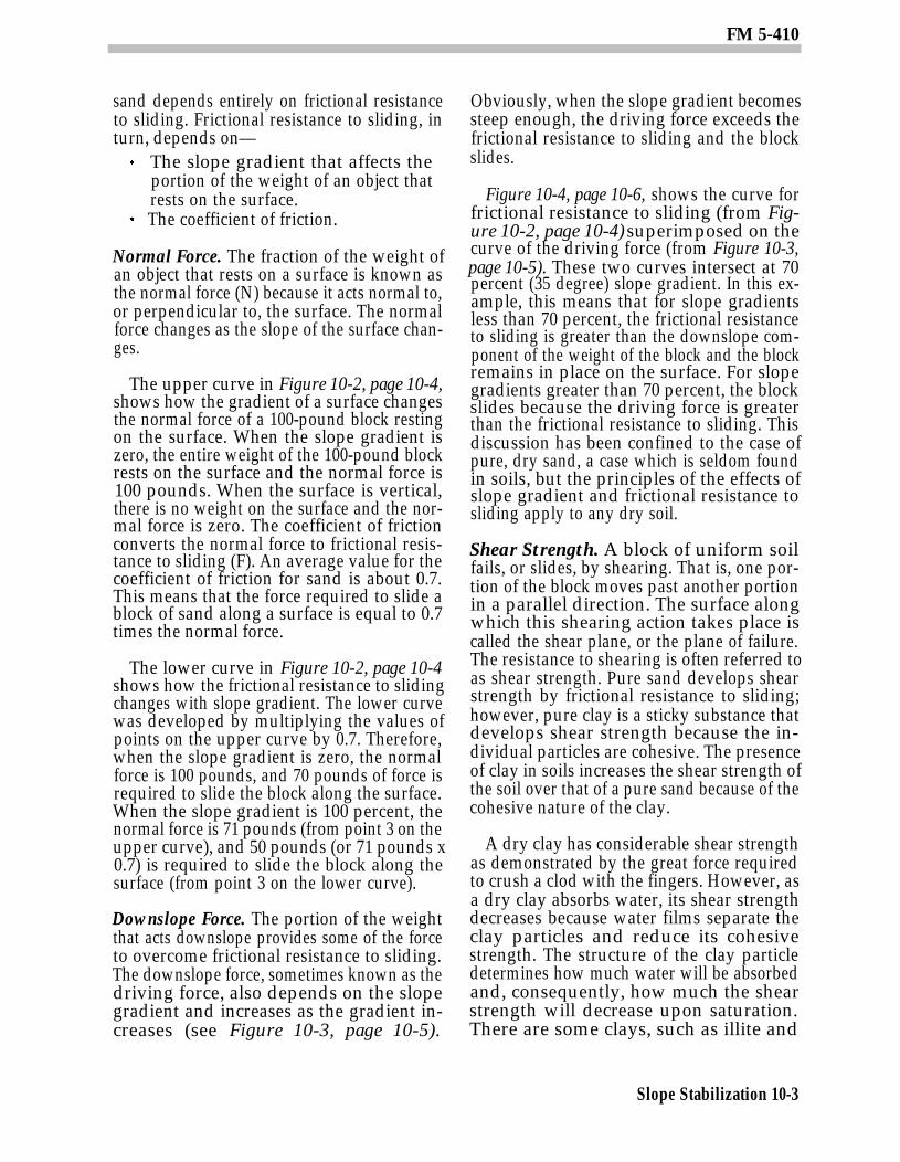
Normal Force. The fraction of the weight ofan object that rests on a surface is known asthe normal force (N) because it acts normal to,or perpendicular to, the surface. The normalforce changes as the slope of the surface chan-ges.
The upper curve in Figure 10-2, page 10-4,shows how the gradient of a surface changesthe normal force of a 100-pound block restingon the surface. When the slope gradient iszero, the entire weight of the 100-pound blockrests on the surface and the normal force is100 pounds. When the surface is vertical,there is no weight on the surface and the nor-mal force is zero. The coefficient of frictionconverts the normal force to frictional resis-tance to sliding (F). An average value for thecoefficient of friction for sand is about 0.7.This means that the force required to slide ablock of sand along a surface is equal to 0.7times the normal force.
The lower curve in Figure 10-2, page 10-4shows how the frictional resistance to slidingchanges with slope gradient. The lower curvewas developed by multiplying the values ofpoints on the upper curve by 0.7. Therefore,when the slope gradient is zero, the normalforce is 100 pounds, and 70 pounds of force isrequired to slide the block along the surface.When the slope gradient is 100 percent, thenormal force is 71 pounds (from point 3 on theupper curve), and 50 pounds (or 71 pounds x0.7) is required to slide the block along thesurface (from point 3 on the lower curve).
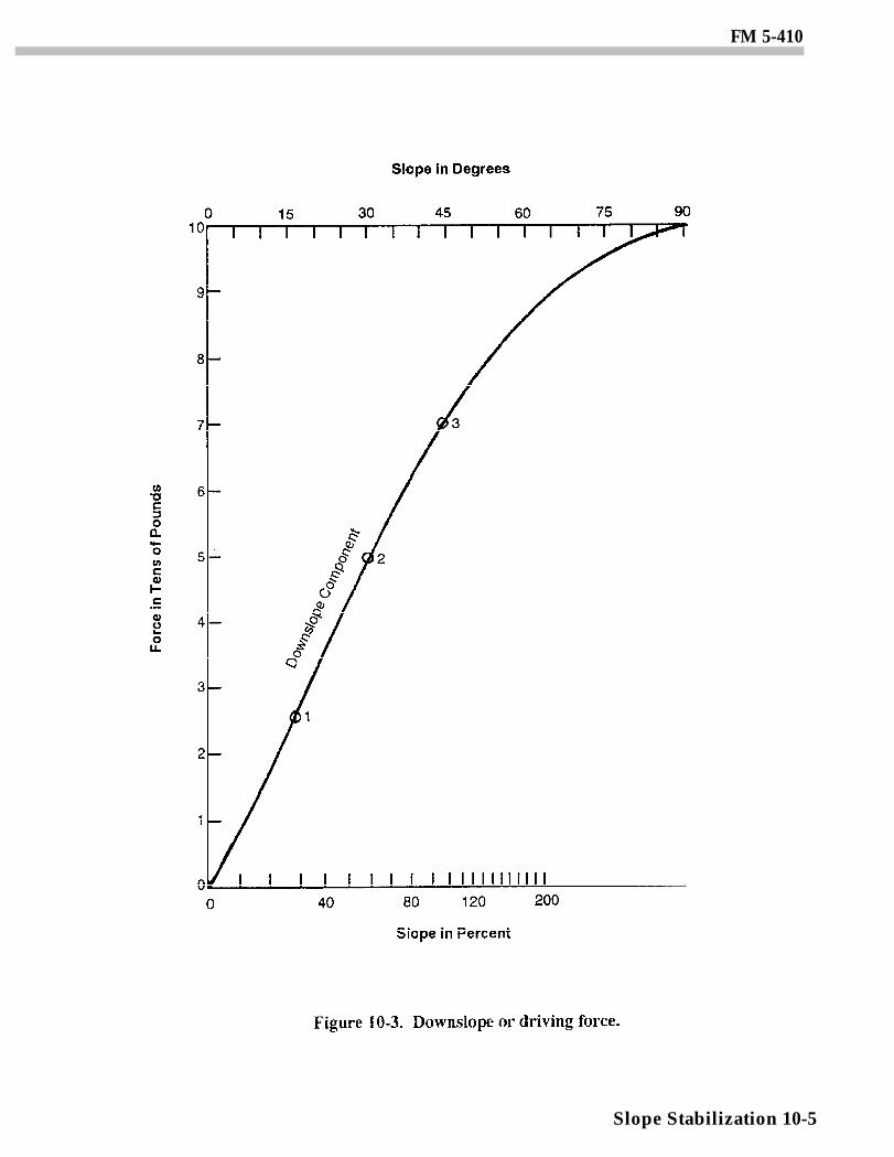
Downslope Force. The portion of the weightthat acts downslope provides some of the forceto overcome frictional resistance to sliding.The downslope force, sometimes known as thedriving force, also depends on the slopegradient and increases as the gradient in-creases (see Figure 10-3, page 10-5).
Obviously, when the slope gradient becomessteep enough, the driving force exceeds thefrictional resistance to sliding and the blockslides.
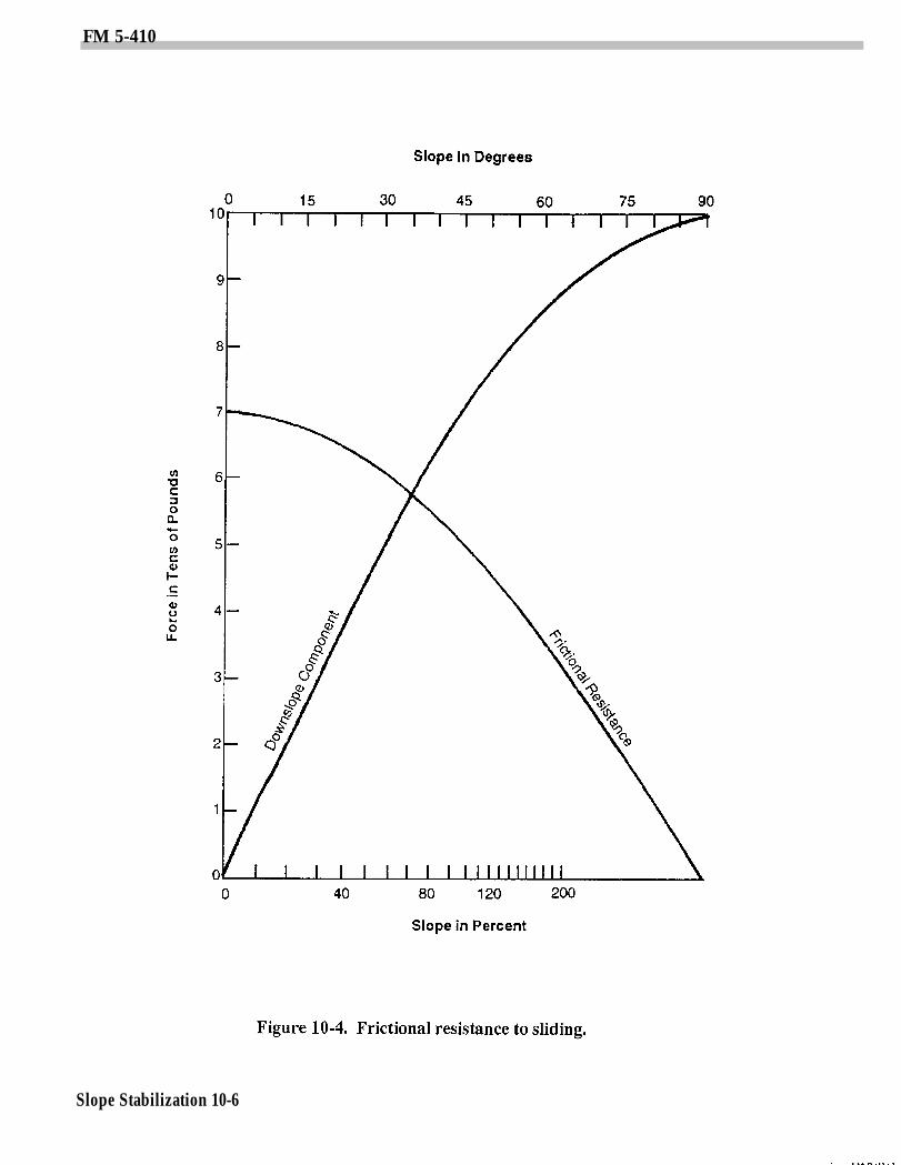
Figure 10-4, page 10-6, shows the curve forfrictional resistance to sliding (from Fig-ure 10-2, page 10-4) superimposed on thecurve of the driving force (from Figure 10-3,page 10-5). These two curves intersect at 70percent (35 degree) slope gradient. In this ex-ample, this means that for slope gradientsless than 70 percent, the frictional resistanceto sliding is greater than the downslope com-ponent of the weight of the block and the blockremains in place on the surface. For slopegradients greater than 70 percent, the blockslides because the driving force is greaterthan the frictional resistance to sliding. Thisdiscussion has been confined to the case ofpure, dry sand, a case which is seldom foundin soils, but the principles of the effects ofslope gradient and frictional resistance tosliding apply to any dry soil.
Shear Strength. A block of uniform soilfails, or slides, by shearing. That is, one por-tion of the block moves past another portionin a parallel direction. The surface alongwhich this shearing action takes place iscalled the shear plane, or the plane of failure.The resistance to shearing is often referred toas shear strength. Pure sand develops shearstrength by frictional resistance to sliding;however, pure clay is a sticky substance thatdevelops shear strength because the in-dividual particles are cohesive. The presenceof clay in soils increases the shear strength ofthe soil over that of a pure sand because of thecohesive nature of the clay.
A dry clay has considerable shear strengthas demonstrated by the great force requiredto crush a clod with the fingers. However, asa dry clay absorbs water, its shear strengthdecreases because water films separate theclay particles and reduce its cohesivestrength. The structure of the clay particledetermines how much water will be absorbedand, consequently, how much the shearstrength will decrease upon saturation.There are some clays, such as illite and
Slope Stabilization 10-3
FM 5-410
Slope Stabilization 10-4
FM 5-410
Slope Stabilization 10-5
FM 5-410
Slope Stabilization 10-6
FM 5-410
kaolinite, that provide relative stability tosoils even when saturated However, asaturated montmorillonite clay causes a sig-nificant decrease in slope stability.Saturated illite and kaolinite clays haveabout 44 percent of their total volume oc-cupied by water compared to about 97 percentfor a saturated montmorillonite clay. Thisexplains why montrnorillonite clay has such ahigh shrink-swell potential (large change involume from wet to dry) and saturated claysof this type have a low shear strength. Thus,the type of clay in a soil has a significant effecton slope stability.
Granitoid rocks tend to weather to sandysoils as the weathering process destroys thegrain-to-grain contact that holds the mineralcrystals together. If these soils remain inplace long enough, they eventually develop asignificant amount of clay. If erosion removesthe weathered material at a rapid rate, theresulting soil is coarse-textured and behavesas a sand for purposes of slope stabilityanalysis. Many soils with a significant claycontent have developed from granitoidmaterial. They have greater shear strengthand support steeper cut faces than agranitoid-derived soil with little clay.
The relative stability among soils dependson a comparison of their shear strength andthe downslope component of the weight of thesoil. For two soils developed from the samegeologic material, the soil with the higher per-centage of illite or kaolinite clay has greatershear strength than a soil with a significantamount of montmorillonite clay.
GroundwaterA common observation is that a hillslope or
the side slopes of a drainageway may be per-fectly stable during the summer but may slideafter the winter rains begin. This seasonalchange in stability is due mainly to thechange in the amount of water i n the pores ofthe soil. The effect of groundwater on slopestability can best be understood by again con-sidering the block of pure sand. Frictionalresistance to sliding in dry sand is developedas the product of the coefficient of friction andthe normal force acting on the surface of the
failure plane. A closeup view of this situationshows that the individual sand g-rains are in-terlocked, or jammed together, by the weightof the sand. The greater the force that causesthis interlocking of sand grains, the greater isthe ability to resist the shear force that iscaused by the downslope component of thesoil weight. As groundwater rises in thesand, the water reduces the normal force be-cause of the buoyant force exerted on eachsand grain as it becomes submerged.
Uplift ForceThe uplift force of the groundwater reduces
the interlocking force on the soil particles,which reduces the frictional resistance to slid-ing. The uplift force of groundwater is equalto 62.4 pounds per foot of water in the soil.The effective normal force is equal to theweight of the soil resting on the surface minusthe uplift force of the groundwater.
The following example illustrates the cal-culation of the effective normal force.
If 100 pounds of’ sand rests on ahorizontal surface and contains 3 in-ches (or 0.25 foot) of groundwater,then the effective normal force is 100- (62.4 x 0.25) = 100 - 15.6 or 84.4pounds. This shows how groundwaterreduces frictional resistance to slid-ing.The frictional resistance to slidingwith this groundwater condition is84.4 x 0.7 (average coefficient of fric-tion for sand), which equals 59.1pounds.As a comparison, for 100 pounds ofdry sand on a horizontal surface thefrictional resistance to sliding is 100 x0.7 or 70 pounds.
The following examples further emphasizehow the presence of ground water candecrease slope stability by reducing the fric-tional resistance to sliding:
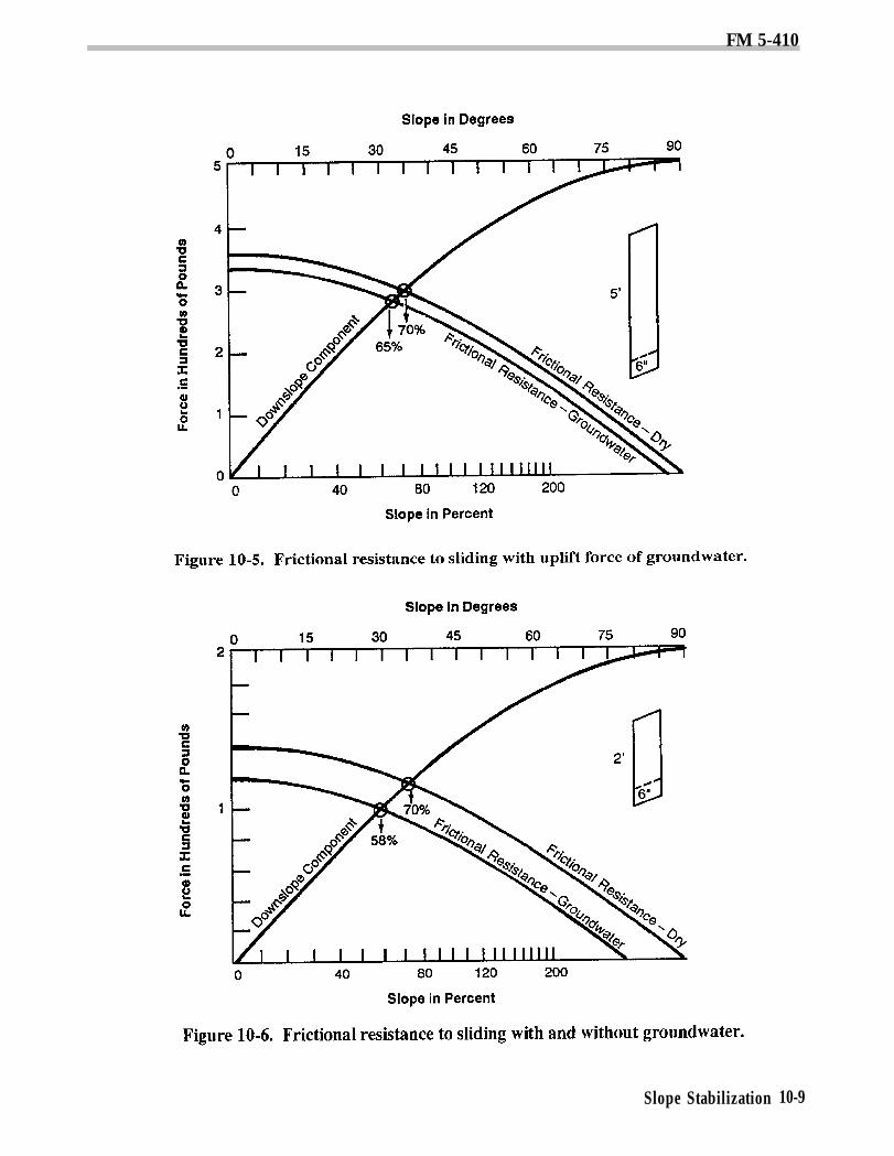
First, a layer of dry sand 5 feet thickis assumed to weigh 100 pounds perfoot of depth. The downslope com-ponent of the dry weight and the fric-tional resistance to sliding for dry
Slope Stabilization 10-7
FM 5-410
sand was calculated for various slopegradients as in Figure 10-2, page 10-4,and Figure 10-3, page 10-5.Next, 6 inches of groundwater is as-sumed to be present and the frictionalresistance to sliding is recalculated,taking into account the uplift force ofthe groundwater. The results of thesecalculations are shown in Figure 10-5.
Note: In a dry condition, sliding occurswhen the slope gradient exceeds 70 per-cent. With 6 inches of groundwater, thesoil slides when the slope gradient ex-ceeds 65 percent.
For a comparison, assume a dry sandlayer only 2 feet thick that weighs100 pounds per foot of depth. Again,assume 6 inches of groundwater andrecalculate the downslope componentof the soil weight and the frictionalresistance to sliding with and withoutthe groundwater (see Figure 10-6).
Note: With 6 inches of groundwater,this thin layer of soil slides when theslope gradient exceeds 58 percent.
These examples demonstrate that the thin-ner soil mantle has a greater potential forsliding under the same ground water condi-tions than a thicker soil mantle. The 6 inchesof groundwater is a greater proportion of thetotal soil thickness for the 2-foot soil than forthe 5-foot soil, and the ratio of uplift force tothe frictional resistance to sliding is greaterfor the 2-foot soil. A pure sand was used inthese examples for the sake of simplicity, butthe principles still apply to soils that containvarying amounts of silt and clay together withsand.
Although adding soil may decrease the ef-fect of uplift force on the frictional resistanceto sliding, it is dangerous to conclude thatslopes can be made stable solely through thisapproach. The added soil reduces uplift force,but it may increase another factor that inturn decreases frictional resistance, resultingin a slope failure. Decreasing the uplift forceof water can be best achieved through a
properly designed groundwater control sys-tem.
Seepage ForceThere is still another way that ground-
water contributes to slope instability, andthat is the seepage force of groundwater as itmoves downslope. The seepage force is thedrag force that moving water exerts on eachindividual soil particle in its path. Therefore,the seepage force contributes to the drivingforce that tends to move masses of soildownslope. The concept of the seepage forcemay be visualized by noting how easily por-tions of a coarse-textured soil may bedislodged from a road cut bank when the soilis conducting a relatively high volume ofgroundwater.
SLOPE FAILURESlope failure includes all mass soil move-
ments on—Man-made slopes (such as road cuts
and fills).Natural slopes (in clear-cut areas or
undisturbed forest).
A classification of slope failure is useful be-cause it provides a common terminology, andit offers clues to the type of slope stabilityproblem that is likely to be encountered.Types of slope and road failures areremarkably consistent with soils, geologicmaterial, and topography. For example, fast-moving debris avalanches or slides develop inshallow, coarse-textured soils on steephillsides; large, rotational slumps occur indeep, saturated soils on gentle to moderateslopes.
Rockfalls and RockslidesRockfalls and rockslides usually originate
in bedded sediments, such as massivesandstone, where the beds are undercut bystream erosion or road excavation. Stabilityis maintained by the—
Competence of the rock.Frictional resistancethe bedding planes.
to sliding along
Slope Stabilization 10-8
FM 5-410
Slope Stabilization 10-9
FM 5-410
These factors are particularly importantwhere the bedding planes dip downslopetoward a road or stream. Rockslides occursuddenly, slide with great speed, and some-times extend entirely across the valleybottom. Slide debris consists of fracturedrock and may include some exceptionallylarge blocks. Road locations through areaswith a potential for rockslides should be ex-amined by specialists who can evaluate thecompetence of the rock and determine the dipof the bedding planes.
Debris Avalanches and Debris FlowsThese two closely related types of slope
failure usually originate on shallow soils thatare relatively low in clay content on slopesover 65 percent. In southeast Alaska, the USForest Service has found that debrisavalanches develop on slopes greater than 65percent on shallow, gravelly soils and thatthis type of slope failure is especially frequenton slopes over 75 percent.
Debris avalanches are the rapid downslopeflowage of masses of loose soil, rock, andforest debris containing varying amounts ofwater. They are like shallow landslidesresulting from frictional failure along a slipsurface that is essentially parallel to thetopographic surface, formed where the ac-cumulated stresses exceed the resistance toshear. The detached soil mantle slidesdownslope above an impermeable boundarywithin the loose debris or at the unweatheredbedrock surface and forms a disarrangeddeposit at the base. Downslope, a debrisavalanche frequently becomes a debris flowbecause of substantial increases in water con-tent. They are caused most frequently whena sudden influx of water reduces the shearstrength of earth material on a steep slope,and they typically follow heavy rainfall.
There are two situations where these typesof slope failure occur in areas with shallowsoil, steep slopes, and heavy seasonal rainfall.
The first situation is an area where streamdevelopment and geologic erosion haveformed high ridges with long slopes and
steep, V-shaped drainages, usually in beddedsedimentary rock. The gradient of many ofthese streams increases sharply from themain stream to the ridge; erosion has createdheadwalls in the upper reaches. The bowl-shaped headwall region is often the junctionfor two or more intermittent stream channelsthat begin at the ridgetop. This leads to aquick rise in ground water levels duringseasonal rains. Past debris avalanches mayhave scoured round-bottom chutes, ortroughs, into the relatively hard bedrock.The headwall region may be covered withonly a shallow soil mantle of precariousstability, and it may show exposed bedrock,which is often dark with ground waterseepage.
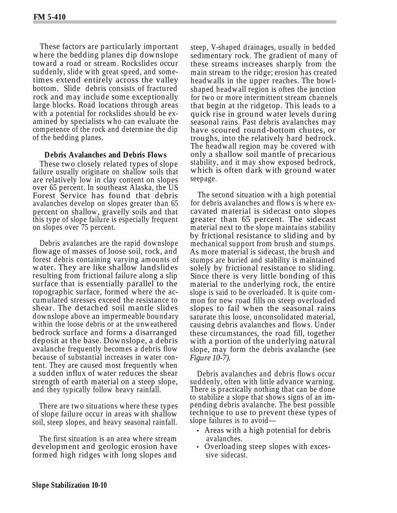
The second situation with a high potentialfor debris avalanches and flows is where ex-cavated material is sidecast onto slopesgreater than 65 percent. The sidecastmaterial next to the slope maintains stabilityby frictional resistance to sliding and bymechanical support from brush and stumps.As more material is sidecast, the brush andstumps are buried and stability is maintainedsolely by frictional resistance to sliding.Since there is very little bonding of thismaterial to the underlying rock, the entireslope is said to be overloaded. It is quite com-mon for new road fills on steep overloadedslopes to fail when the seasonal rainssaturate this loose, unconsolidated material,causing debris avalanches and flows. Underthese circumstances, the road fill, togetherwith a portion of the underlying naturalslope, may form the debris avalanche (seeFigure 10-7).
Debris avalanches and debris flows occursuddenly, often with little advance warning.There is practically nothing that can be doneto stabilize a slope that shows signs of an im-pending debris avalanche. The best possibletechnique to use to prevent these types ofslope failures is to avoid—
Areas with a high potential for debrisavalanches.Overloading steep slopes with exces-sive sidecast.
Slope Stabilization 10-10
FM 5-410
Engineers should learn the vegetative andsoil indicators of this type of unstable terrain,especially for those areas with high seasonalgroundwater levels.
If unstable terrain must be crossed byroads, then radical changes in road grade androad width may be required to minimize sitedisturbance. Excavated material may needto be hauled away to keep overloading of un-stable slopes to an absolute minimum. Thelocation of safe disposal sites for this materialmay be a serious problem in steep terrainwith sharp ridges. Site selection will requirejust as much attention to the principles ofslope stability as to the location and construc-tion of the remainder of the road.
Slumps and EarthflowsSlumps and earthflows usually occur in
deep, moderately fine- or fine-textured soilsthat contain a significant amount of siltand/or clay. In this case, shear strength is acombination of cohesive shear strength andfrictional resistance to sliding. As noted ear-lier, groundwater not only reduces frictionalresistance to shear, but it also sharplyreduces cohesive shear strength. Slumps areslope failures where one or more blocks of soil
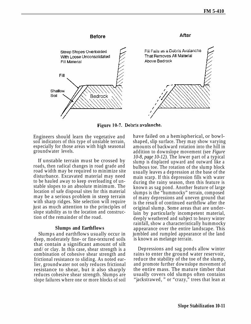
have failed on a hemispherical, or bowl-shaped, slip surface. They may show varyingamounts of backward rotation into the hill inaddition to downslope movement (see Figure10-8, page 10-12). The lower part of a typicalslump is displaced upward and outward like abulbous toe. The rotation of the slump blockusually leaves a depression at the base of themain scarp. If this depression fills with waterduring the rainy season, then this feature isknown as sag pond. Another feature of largeslumps is the “hummocky” terrain, composedof many depressions and uneven ground thatis the result of continued earthflow after theoriginal slump. Some areas that are under-lain by particularly incompetent material,deeply weathered and subject to heavy winterrainfall, show a characteristically hummockyappearance over the entire landscape. Thisjumbled and rumpled appearance of the landis known as melange terrain.
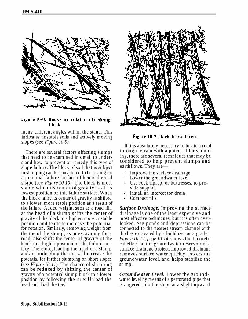
Depressions and sag ponds allow winterrains to enter the ground water reservoir,reduce the stability of the toe of the slump,and promote further downslope movement ofthe entire mass. The mature timber thatusually covers old slumps often contains“jackstrawed, ” or “crazy,” trees that lean at
Slope Stabilization 10-11
FM 5-410
many different angles within the stand. Thisindicates unstable soils and actively movingslopes (see Figure 10-9).
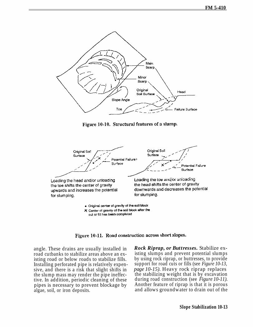
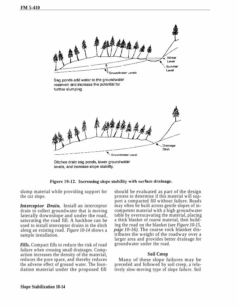
There are several factors affecting slumpsthat need to be examined in detail to under-stand how to prevent or remedy this type ofslope failure. The block of soil that is subjectto slumping can be considered to be resting ona potential failure surface of hemisphericalshape (see Figure 10-10). The block is moststable when its center of gravity is at itslowest position on this failure surface. Whenthe block fails, its center of gravity is shiftedto a lower, more stable position as a result ofthe failure. Added weight, such as a road fill,at the head of a slump shifts the center ofgravity of the block to a higher, more unstableposition and tends to increase the potentialfor rotation. Similarly, removing weight fromthe toe of the slump, as in excavating for aroad, also shifts the center of gravity of theblock to a higher position on the failure sur-face. Therefore, loading the head of a slumpand/or unloading the toe will increase thepotential for further slumping on short slopes(see Figure 10-11). The chance of slumpingcan be reduced by shifting the center ofgravity of a potential slump block to a lowerposition by following the rule: Unload thehead and load the toe.
If it is absolutely necessary to locate a roadthrough terrain with a potential for slump-ing, there are several techniques that may beconsidered to help prevent slumps andearthflows. They are—
Improve the surface drainage.Lower the groundwater level.Use rock riprap, or buttresses, to pro-vide support.Install an interceptor drain.Compact fills.
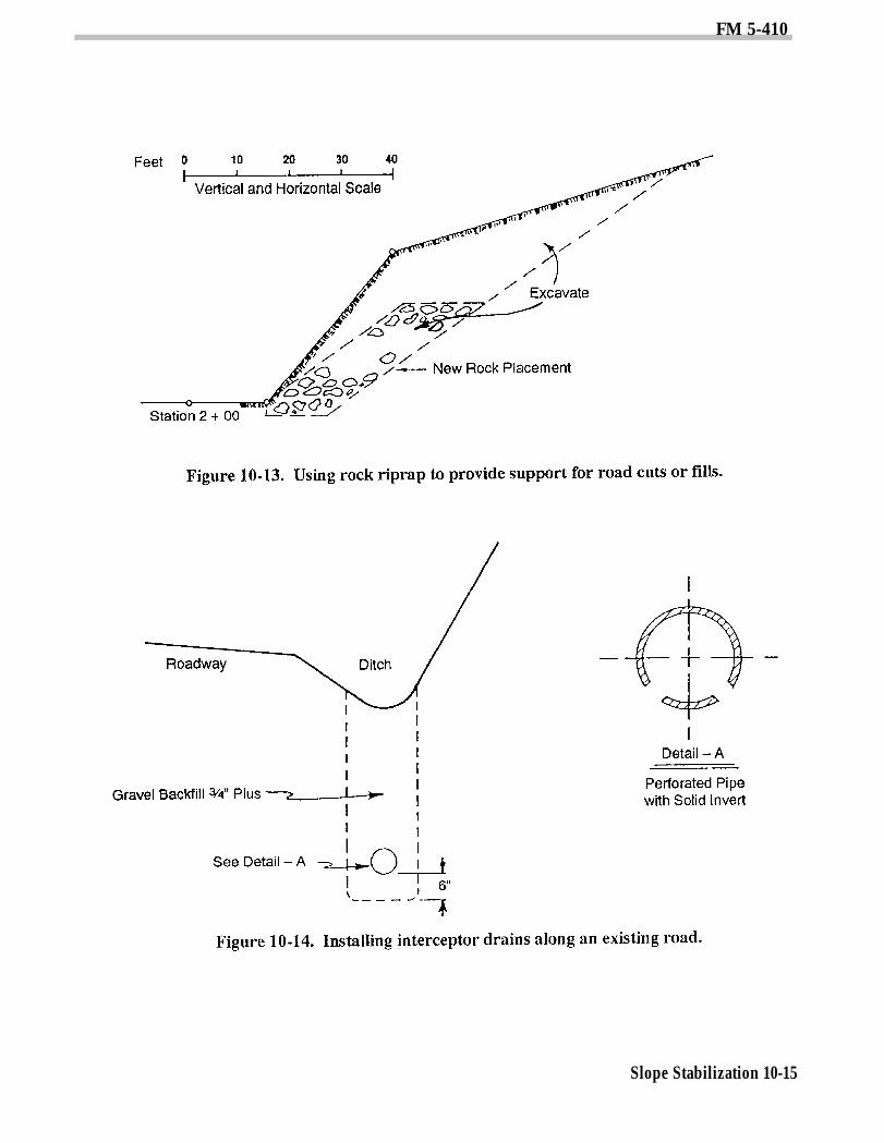
Surface Drainage. Improving the surfacedrainage is one of the least expensive andmost effective techniques, but it is often over-looked. Sag ponds and depressions can beconnected to the nearest stream channel withditches excavated by a bulldozer or a grader.Figure 10-12, page 10-14, shows the theoreti-cal effect on the groundwater reservoir of asurface drainage project. Improved drainageremoves surface water quickly, lowers thegroundwater level, and helps stabilize theslump.
Groundwater Level. Lower the ground-water level by means of a perforated pipe thatis augered into the slope at a slight upward
Slope Stabilization 10-12
FM 5-410
angle. These drains are usually installed inroad cutbanks to stabilize areas above an ex-isting road or below roads to stabilize fills.Installing perforated pipe is relatively expen-sive, and there is a risk that slight shifts inthe slump mass may render the pipe ineffec-tive. In addition, periodic cleaning of thesepipes is necessary to prevent blockage byalgae, soil, or iron deposits.
Rock Riprap, or Buttresses. Stabilize ex-isting slumps and prevent potential slumpsby using rock riprap, or buttresses, to providesupport for road cuts or fills (see Figure 10-13,page 10-15). Heavy rock riprap replacesthe stabilizing weight that is by excavationduring road construction (see Figure 10-11).Another feature of riprap is that it is porousand allows groundwater to drain out of the
Slope Stabilization 10-13
FM 5-410
slump material while providing support forthe cut slope.
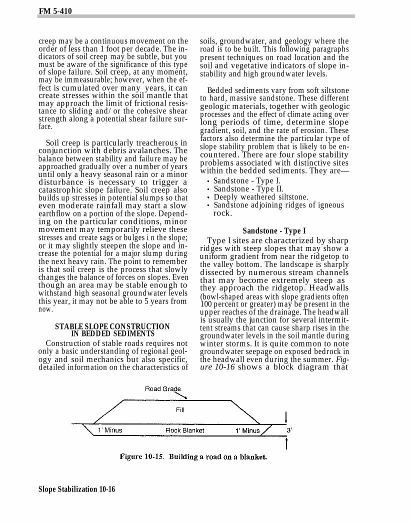
Interceptor Drain. Install an interceptordrain to collect groundwater that is movinglaterally downslope and under the road,saturating the road fill. A backhoe can beused to install interceptor drains in the ditchalong an existing road. Figure 10-14 shows asample installation.
Fills. Compact fills to reduce the risk of roadfailure when crossing small drainages. Comp-action increases the density of the material,reduces the pore space, and thereby reducesthe adverse effect of ground water. The foun-dation material under the proposed fill
Slope Stabilization 10-14
should be evaluated as part of the designprocess to determine if this material will sup-port a compacted fill without failure. Roadsmay often be built across gentle slopes of in-competent material with a high groundwatertable by overexcavating the material, placinga thick blanket of coarse material, then build-ing the road on the blanket (see Figure 10-15,page 10-16). The coarse rock blanket dis-tributes the weight of the roadway over alarger area and provides better drainage forgroundwater under the road.
Soil CreepMany of these slope failures may be
preceded and followed by soil creep, a rela-tively slow-moving type of slope failure. Soil
FM 5-410
Slope Stabilization 10-15
FM 5-410
creep may be a continuous movement on theorder of less than 1 foot per decade. The in-dicators of soil creep may be subtle, but youmust be aware of the significance of this typeof slope failure. Soil creep, at any moment,may be immeasurable; however, when the ef-fect is cumulated over many years, it cancreate stresses within the soil mantle thatmay approach the limit of frictional resis-tance to sliding and/or the cohesive shearstrength along a potential shear failure sur-face.
Soil creep is particularly treacherous inconjunction with debris avalanches. Thebalance between stability and failure may beapproached gradually over a number of yearsuntil only a heavy seasonal rain or a minordisturbance is necessary to trigger acatastrophic slope failure. Soil creep alsobuilds up stresses in potential slumps so thateven moderate rainfall may start a slowearthflow on a portion of the slope. Depend-ing on the particular conditions, minormovement may temporarily relieve thesestresses and create sags or bulges i n the slope;or it may slightly steepen the slope and in-crease the potential for a major slump duringthe next heavy rain. The point to rememberis that soil creep is the process that slowlychanges the balance of forces on slopes. Eventhough an area may be stable enough towithstand high seasonal groundwater levelsthis year, it may not be able to 5 years fromnow.
STABLE SLOPE CONSTRUCTIONIN BEDDED SEDIMENTS
Construction of stable roads requires notonly a basic understanding of regional geol-ogy and soil mechanics but also specific,detailed information on the characteristics of
soils, groundwater, and geology where theroad is to be built. This following paragraphspresent techniques on road location and thesoil and vegetative indicators of slope in-stability and high groundwater levels.
Bedded sediments vary from soft siltstoneto hard, massive sandstone. These differentgeologic materials, together with geologicprocesses and the effect of climate acting overlong periods of time, determine slopegradient, soil, and the rate of erosion. Thesefactors also determine the particular type ofslope stability problem that is likely to be en-countered. There are four slope stabilityproblems associated with distinctive siteswithin the bedded sediments. They are—
Sandstone - Type I.Sandstone - Type II.Deeply weathered siltstone.Sandstone adjoining ridges of igneousrock.
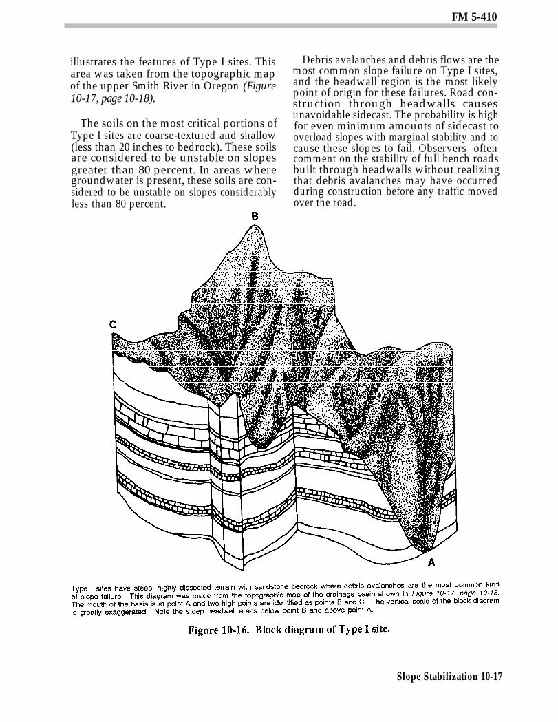
Sandstone - Type IType I sites are characterized by sharp
ridges with steep slopes that may show auniform gradient from near the ridgetop tothe valley bottom. The landscape is sharplydissected by numerous stream channelsthat may become extremely steep asthey approach the ridgetop. Headwalls(bowl-shaped areas with slope gradients often100 percent or greater) may be present in theupper reaches of the drainage. The headwallis usually the junction for several intermit-tent streams that can cause sharp rises in thegroundwater levels in the soil mantle duringwinter storms. It is quite common to notegroundwater seepage on exposed bedrock inthe headwall even during the summer. Fig-ure 10-16 shows a block diagram that
Slope Stabilization 10-16
FM 5-410
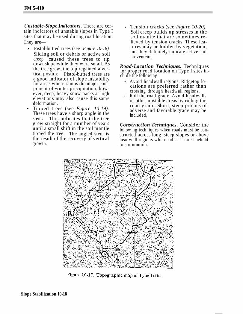
illustrates the features of Type I sites. Thisarea was taken from the topographic mapof the upper Smith River in Oregon (Figure10-17, page 10-18).
The soils on the most critical portions ofType I sites are coarse-textured and shallow(less than 20 inches to bedrock). These soilsare considered to be unstable on slopesgreater than 80 percent. In areas wheregroundwater is present, these soils are con-sidered to be unstable on slopes considerablyless than 80 percent.
Debris avalanches and debris flows are themost common slope failure on Type I sites,and the headwall region is the most likelypoint of origin for these failures. Road con-struction through headwalls causesunavoidable sidecast. The probability is highfor even minimum amounts of sidecast tooverload slopes with marginal stability and tocause these slopes to fail. Observers oftencomment on the stability of full bench roadsbuilt through headwalls without realizingthat debris avalanches may have occurredduring construction before any traffic movedover the road.
Slope Stabilization 10-17
FM 5-410
Unstable-Slope Indicators. There are cer-tain indicators of unstable slopes in Type Isites that may be used during road location.They are—
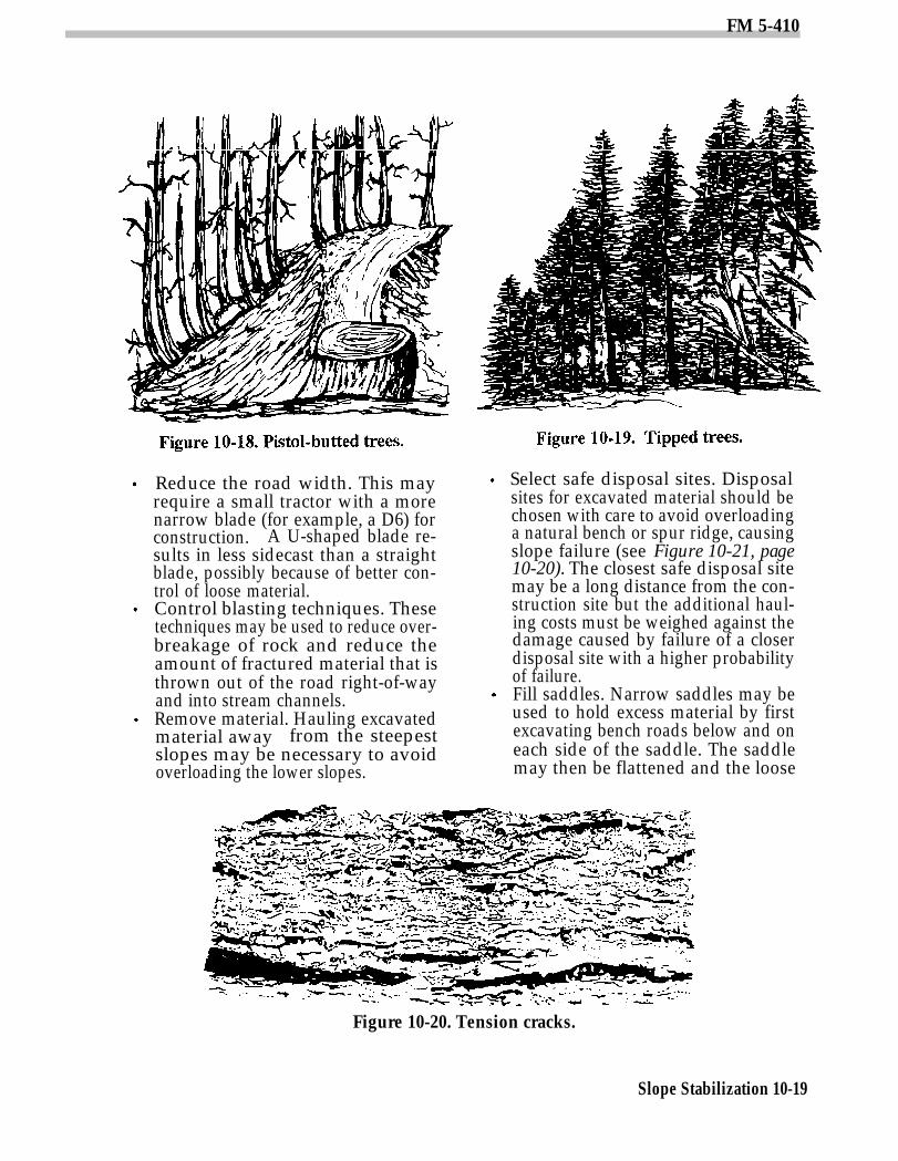
Pistol-butted trees (see .Figure 10-18).Sliding soil or debris or active soilcreep caused these trees to tipdownslope while they were small. Asthe tree grew, the top regained a ver-tical posture. Pistol-butted trees area good indicator of slope instabilityfor areas where rain is the major com-ponent of winter precipitation; how-ever, deep, heavy snow packs at highelevations may also cause this samedeformation.Tipped trees (see Figure 10-19).These trees have a sharp angle in thestem. This indicates that the treegrew straight for a number of yearsuntil a small shift in the soil mantletipped the tree. The angled stem isthe result of the recovery of verticalgrowth.
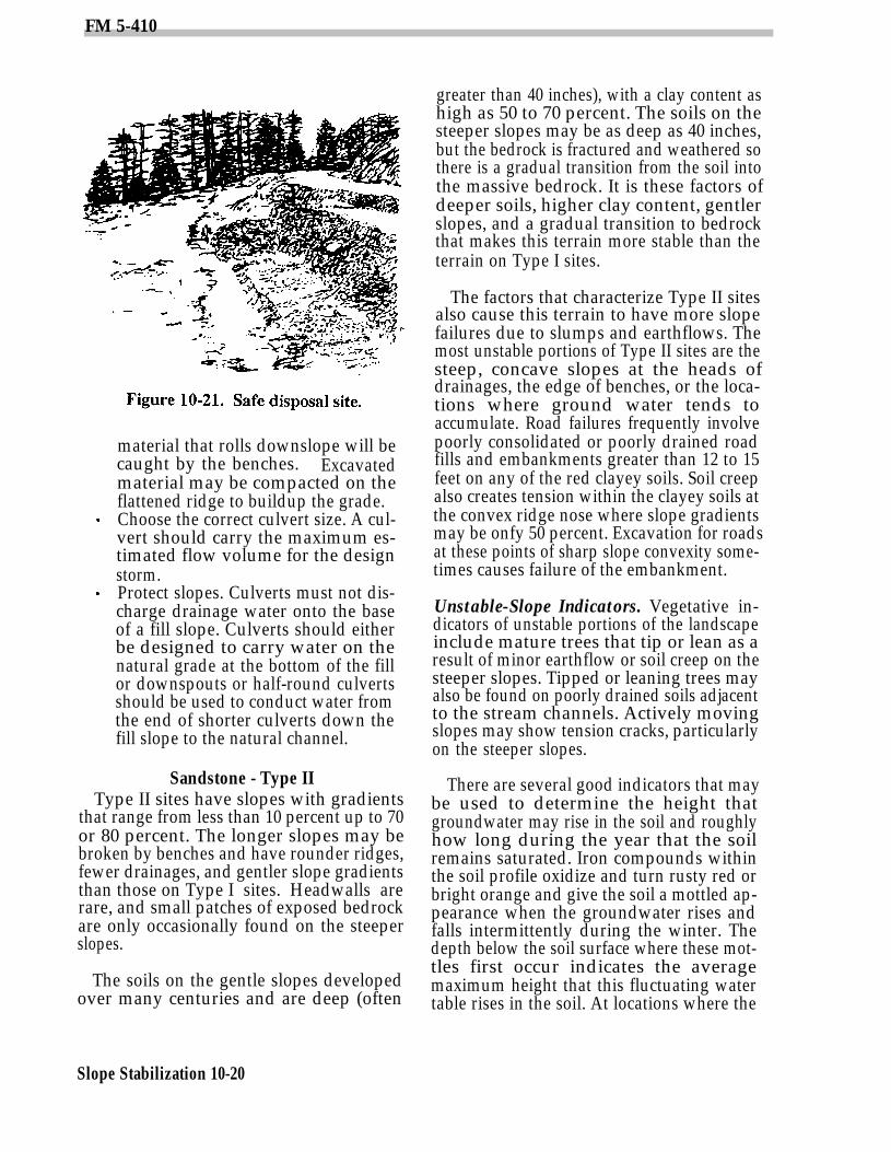
Tension cracks (see Figure 10-20).Soil creep builds up stresses in thesoil mantle that are sometimes re-lieved by tension cracks. These fea-tures may be hidden by vegetation,but they definitely indicate active soilmovement.
Road-Location Techniques. Techniquesfor proper road location on Type I sites in-clude the following:
Avoid headwall regions. Ridgetop lo-cations are preferred rather thancrossing through headwall regions.Roll the road grade. Avoid headwallsor other unstable areas by rolling theroad grade. Short, steep pitches ofadverse and favorable grade may beincluded,
Construction Techniques. Consider thefollowing techniques when roads must be con-structed across long, steep slopes or aboveheadwall regions where sidecast must beheldto a minimum:
Slope Stabilization 10-18
FM 5-410
Reduce the road width. This mayrequire a small tractor with a morenarrow blade (for example, a D6) forconstruction. A U-shaped blade re-sults in less sidecast than a straightblade, possibly because of better con-trol of loose material.Control blasting techniques. Thesetechniques may be used to reduce over-breakage of rock and reduce theamount of fractured material that isthrown out of the road right-of-wayand into stream channels.Remove material. Hauling excavatedmaterial away from the steepestslopes may be necessary to avoidoverloading the lower slopes.
Select safe disposal sites. Disposalsites for excavated material should bechosen with care to avoid overloadinga natural bench or spur ridge, causingslope failure (see Figure 10-21, page10-20). The closest safe disposal sitemay be a long distance from the con-struction site but the additional haul-ing costs must be weighed against thedamage caused by failure of a closerdisposal site with a higher probabilityof failure.Fill saddles. Narrow saddles may beused to hold excess material by firstexcavating bench roads below and oneach side of the saddle. The saddlemay then be flattened and the loose
Figure 10-20. Tension cracks.
Slope Stabilization 10-19
FM 5-410
material that rolls downslope will becaught by the benches. Excavatedmaterial may be compacted on theflattened ridge to buildup the grade.Choose the correct culvert size. A cul-vert should carry the maximum es-timated flow volume for the designstorm.Protect slopes. Culverts must not dis-charge drainage water onto the baseof a fill slope. Culverts should eitherbe designed to carry water on thenatural grade at the bottom of the fillor downspouts or half-round culvertsshould be used to conduct water fromthe end of shorter culverts down thefill slope to the natural channel.
Sandstone - Type IIType II sites have slopes with gradients
that range from less than 10 percent up to 70or 80 percent. The longer slopes may bebroken by benches and have rounder ridges,fewer drainages, and gentler slope gradientsthan those on Type I sites. Headwalls arerare, and small patches of exposed bedrockare only occasionally found on the steeperslopes.
The soils on the gentle slopes developedover many centuries and are deep (often
Slope Stabilization 10-20
greater than 40 inches), with a clay content ashigh as 50 to 70 percent. The soils on thesteeper slopes may be as deep as 40 inches,but the bedrock is fractured and weathered sothere is a gradual transition from the soil intothe massive bedrock. It is these factors ofdeeper soils, higher clay content, gentlerslopes, and a gradual transition to bedrockthat makes this terrain more stable than theterrain on Type I sites.
The factors that characterize Type II sitesalso cause this terrain to have more slopefailures due to slumps and earthflows. Themost unstable portions of Type II sites are thesteep, concave slopes at the heads ofdrainages, the edge of benches, or the loca-tions where ground water tends toaccumulate. Road failures frequently involvepoorly consolidated or poorly drained roadfills and embankments greater than 12 to 15feet on any of the red clayey soils. Soil creepalso creates tension within the clayey soils atthe convex ridge nose where slope gradientsmay be onfy 50 percent. Excavation for roadsat these points of sharp slope convexity some-times causes failure of the embankment.
Unstable-Slope Indicators. Vegetative in-dicators of unstable portions of the landscapeinclude mature trees that tip or lean as aresult of minor earthflow or soil creep on thesteeper slopes. Tipped or leaning trees mayalso be found on poorly drained soils adjacentto the stream channels. Actively movingslopes may show tension cracks, particularlyon the steeper slopes.
There are several good indicators that maybe used to determine the height thatgroundwater may rise in the soil and roughlyhow long during the year that the soilremains saturated. Iron compounds withinthe soil profile oxidize and turn rusty red orbright orange and give the soil a mottled ap-pearance when the groundwater rises andfalls intermittently during the winter. Thedepth below the soil surface where these mot-tles first occur indicates the averagemaximum height that this fluctuating watertable rises in the soil. At locations where the
FM 5-410
water table remains for long periods duringthe year, the iron compounds are chemicallyreduced and give the soil profile a gray orbluish-gray appearance. The occurrence ofthese gleyed soils indicates a soil that issaturated for much of the year. Occasionally,mottles may appear above a gleyed subsoil,which indicates a seasonally fluctuatingwater table above a subsoil that is subject toprolonged saturation. Engineers should beaware of the significance of mottled andgleyed soils that are exposed during road con-struction. These indicators give clues to theneed for drainage or extra attention concern-ing the suitability of a subsoil for foundationmaterial.
Road-Location Techniques. Techniquesfor locating stable roads on Type II sites in-clude the following
Avoid steep concave basins. Do notlocate roads through these areaswhere stability is questionable, as in-dicated by vegetation and topography.Ridgetop locations are preferred.Choose stable benches. Benches mayoffer an opportunity for location ofroads and landings, but these benchesshould be examined carefully to seethat they are supported by rock andare not ancient, weathered slumpswith marginal stability.Avoid cracked soil. Avoid locating aroad around convex ridge noses orbelow the edge of benches where ten-sion cracks or catsteps indicate a highprobability for embankment failure.
Construction Techniques. Certain designand construction practices should be con-sidered when building roads in this terrain.
Avoid overconstruction. If it is neces-sary to build a road across steepdrainages, avoid overconstruction andhaul excess material away to avoidoverloading the slopes.Avoid high cut embankments. An en-gineer or soil scientist may be able tosuggest a maximum height at theditch line for the particular soil andsituation. A rule-of-thumb estimate
for maximum height for a cut bank indeep, clayey soils is 12 to 15 feet.Pay special attention to fills. Fills ofclayey material over steep stream cross-ings may fail if the material is notcompacted and if groundwater sat-urates the base of the fill. Fill failuresin this wet, clayey material on steepslopes tend to move initially as aslump, then may change to a mudflowdown the drainage. To avoid this,compact the fill to accepted engineer-ing standards, paying special atten-tion to proper lift thicknesses, mois-ture content, and foundation condi-tions. Also, design drainage features,where necessary, to control ground-water in the base of a fill. For ex-ample, consider either a perforatedpipe encased in a crushed rock filteror a blanket of crushed rock underthe entire fill.
Deeply Weathered SiltstoneThis stability problem originates in
siltstone that is basically incompetent andeasily weathered. Slumps and earthflows,both large and small, are very common whenthis material is subjected to heavy winterrainfall. The landscape may exhibit a benchyor hummocky appearance. Slopes withgradients as low as 24 percent may be con-sidered unstable in deeply weatheredsiltstone with abundant water.
Unstable-Slope Indicators. Vegetativeand topographic indicators of slope instabilityare numerous. Large patches of plants asso-ciated with set soils indicate high ground-water levels and impeded drainage. Conifersmay tip or lean due to earthflow or soil creep.Slumps cause numerous benches, some ofwhich show sag ponds. Blocks of soil may sagand leave large cracks, which gradually fill inwith debris and living vegetation. The sharpcontours of these features soften in time untilthe cracks appear as “blind drainages” or sec-tions of stream channel that are blocked atboth ends. The cracks collect water, keep thegroundwater reservoir charged, and con-tribute to active soil movement.
Slope Stabilization 10-21
FM 5-410
Road-Location Techniques. Techniquesfor locating stable roads through terrain thathas been derived from deeply weatheredsilt-stone include the following
Check for indicators of groundwater.Avoid locating roads through areaswhere groundwater levels are highand where slope stability is likely tobe at its worst. Such locations may beindicated by hydrophytes, tipped orleaning trees, and mottled or gleyedsoils.Consider ridges. Ridgetop locationsmay be best because groundwaterdrainage is better there. Also, the un-derlying rock may be harder and mayprovide more stable roadbuildingmaterial than weathered siltstone.Ensure adequate reconnaissance.Take pains to scout the terrain awayfrom the proposed road location,using aerial photos and ground recon-naissance to be sure that the line doesnot run through or under an ancientslump that may become unstable dueto the road construction.
Construction Techniques. Special roaddesign and construction techniques for thistype of terrain may include the following
Drainage ditches. Every effort shouldbe made to improve drainage, bothsurface and subsurface, since ground-water is the major factor contributingto slope instability for this material.Sag ponds and bogs may be drainedwith ditches excavated by tractor orwith ditching dynamite.Culverts. Extra culverts should beused to prevent water from pendingabove the road and saturating theroad prism and adjacent slopes.Road ditches. They should be careful-ly graded to provide plenty of fall tokeep water moving. A special effortshould be made to keep ditches andculverts clean following con-struction.
Slope Stabilization 10-22
Sandsone Adjoining Ridgesof Igneous Rock
This slope stability problem in bedded sedi-ments is caused by remnants of sandstoneadjoining ridges of igneous rock. As a generalrule, any contact zone between sedimentarymaterial and igneous material is likely tohave slope stability problems.
Unstable-Slope Indicators. The igneousrock may have caused fracturing and partialmetamorphosis of the sedimentary rock atthe time of intrusion. Also, water is usuallyabundant at the contact zone because the igneous material is relatively impermeablecompared to the sediments; therefore, thesedimentary rock may be deeply weathered.
Road-Location Techniques. Special roadlocation techniques for this type of slopestability problem include the following
Pay attention to the contact zone.Examine the terrain carefully on theground and on aerial photos todetermine if the mass of sandstone islarge or small relative to the igneousrock mass. If the sandstone is in theform of a relatively large spur ridge,then the contact zone deserves specialattention. The contact zone should becrossed as high as possible wheregroundwater accumulation is at aminimum. Elsewhere on the ridge ofsandstone, the stabilty problems arethe same as for Type I or Type IIsandstone.Consider an alternative location. Ifthe remnant of sandstone is relativelysmall, such as a ridge nose, then theentire mass of sandstone may becreeping rapidly enough to be con-sidered unstable and the road shouldbe located above this material in themore stable igneous rock.
Construction Techniques. Design andconstruction techniques to be considered areas follows:
Avoid high embankments. The sedi-mentary rock in the contact zone is

FM 5-410
likely to be fractured and may besomewhat metamorphosed as a resultof the intrusion of igneous rock. In ad-dition, the accumulation of ground-water is likely to have caused ex-tensive weathering of this material.The road cut height at the ditch lineshould be kept as low as possiblethrough this zone. Support by rock
riprap may be necessary if the cutembankment must be high.Ensure good drainage. It is good apractice to put a culvert at the contactzone with good gradient on theditches to keep the contact zone welldrained. Other drainage measures,such as drain tile or perforated pipe,may be necessary.
Slope Stabilization 10-23