Embed Size (px)
Citation preview
Smart Cathodic Protection RetrofitSmart Cathodic Protection RetrofitSmart Cathodic Protection Retrofit Smart Cathodic Protection Retrofit Methods for ROV InstallationMethods for ROV Installation
Jim BrittonDeepwater Corrosion Services Inc.
Houston, TX.,
UTC 2008 Bergen © Deepwater Corrosion Services Inc. 2008
Presentation OutlinePresentation OutlinePresentation OutlinePresentation Outline
IntroductionKey Factors to Consider
Anode SystemTie-Back SystemMonitoring & VerificationMonitoring & Verification
Project Case History OutlinesNorthern North Sea PipelinesNorthern North Sea PipelinesGulf of Mexico Subsea Field DevelopmentGulf of Mexico SPAR Risers & Wellheads
UTC 2008 Bergen © Deepwater Corrosion Services Inc. 2008
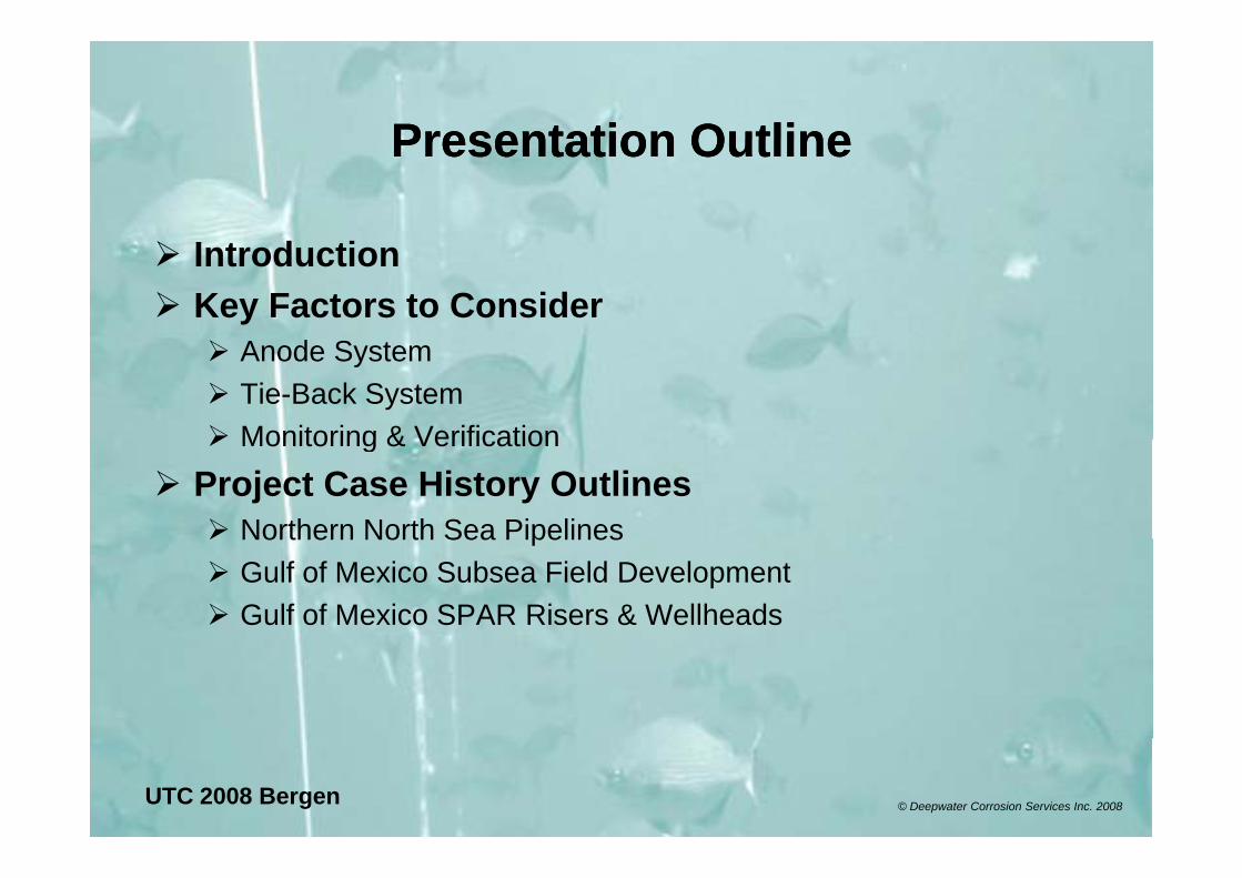
IntroductionIntroductionIntroductionIntroductionROV friendly methods
d l d fwere developed out of necessity to fix GOM gaffs – water depth.
ROV usage is on the increase irrespective ofincrease irrespective of water depth.
Sacrificial systems presented, but ROV’s have successfullyhave successfully retrofitted ICCP
UTC 2008 Bergen © Deepwater Corrosion Services Inc. 2008
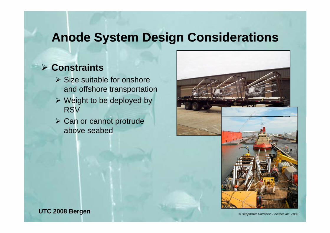
Anode System Design ConsiderationsAnode System Design ConsiderationsAnode System Design ConsiderationsAnode System Design Considerations
ConstraintsSize suitable for onshore and offshore transportationand offshore transportationWeight to be deployed by RSVCan or cannot protrude above seabed
UTC 2008 Bergen © Deepwater Corrosion Services Inc. 2008
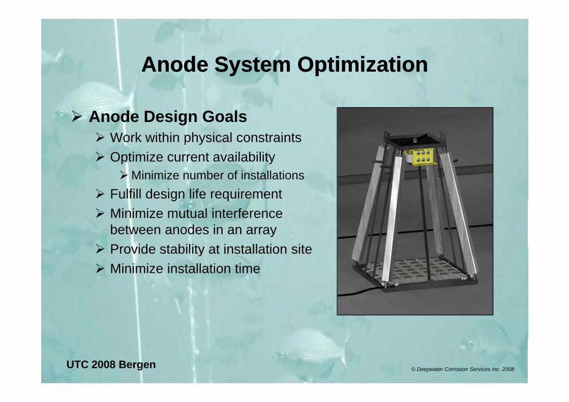
Anode System OptimizationAnode System OptimizationAnode System OptimizationAnode System Optimization
Anode Design GoalsWork within physical constraintsOptimize current availabilityOptimize current availability
Minimize number of installationsFulfill design life requirementg qMinimize mutual interference between anodes in an arrayProvide stability at installation siteProvide stability at installation siteMinimize installation time
UTC 2008 Bergen © Deepwater Corrosion Services Inc. 2008
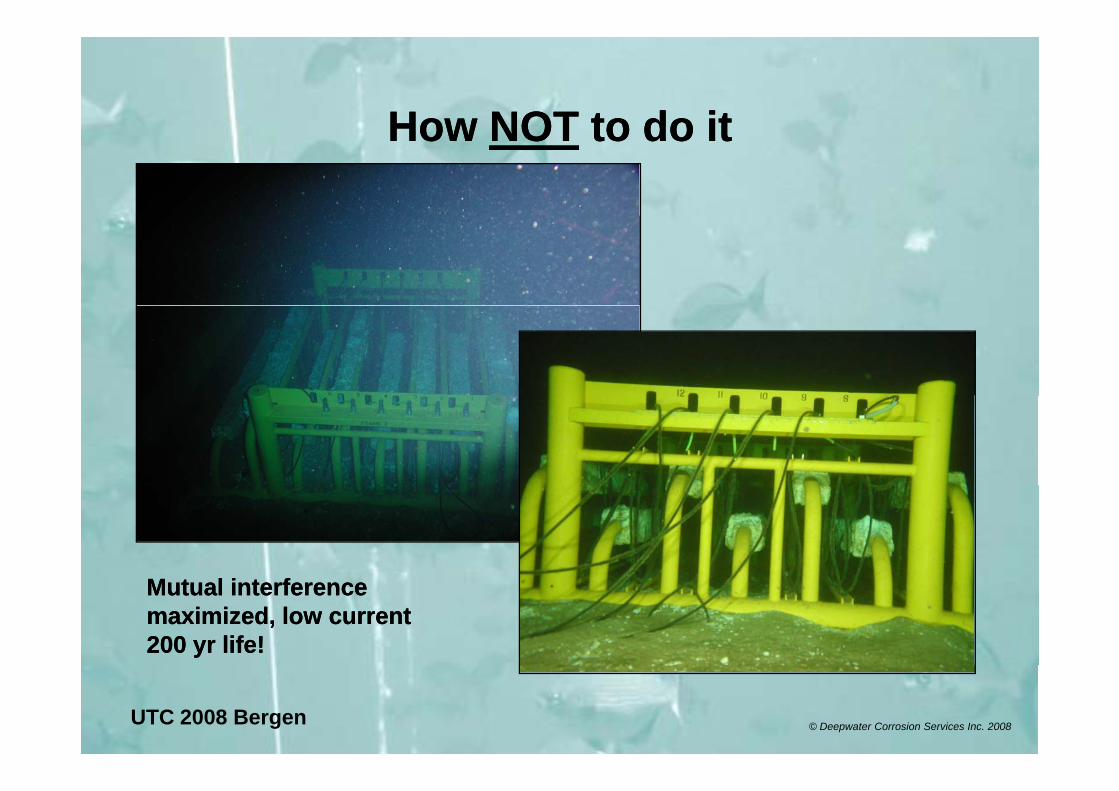
HowHow NOTNOT to do itto do itHow How NOTNOT to do itto do it
Mutual interference Mutual interference maximized, low current maximized, low current 200 yr life!200 yr life!
UTC 2008 Bergen © Deepwater Corrosion Services Inc. 2008
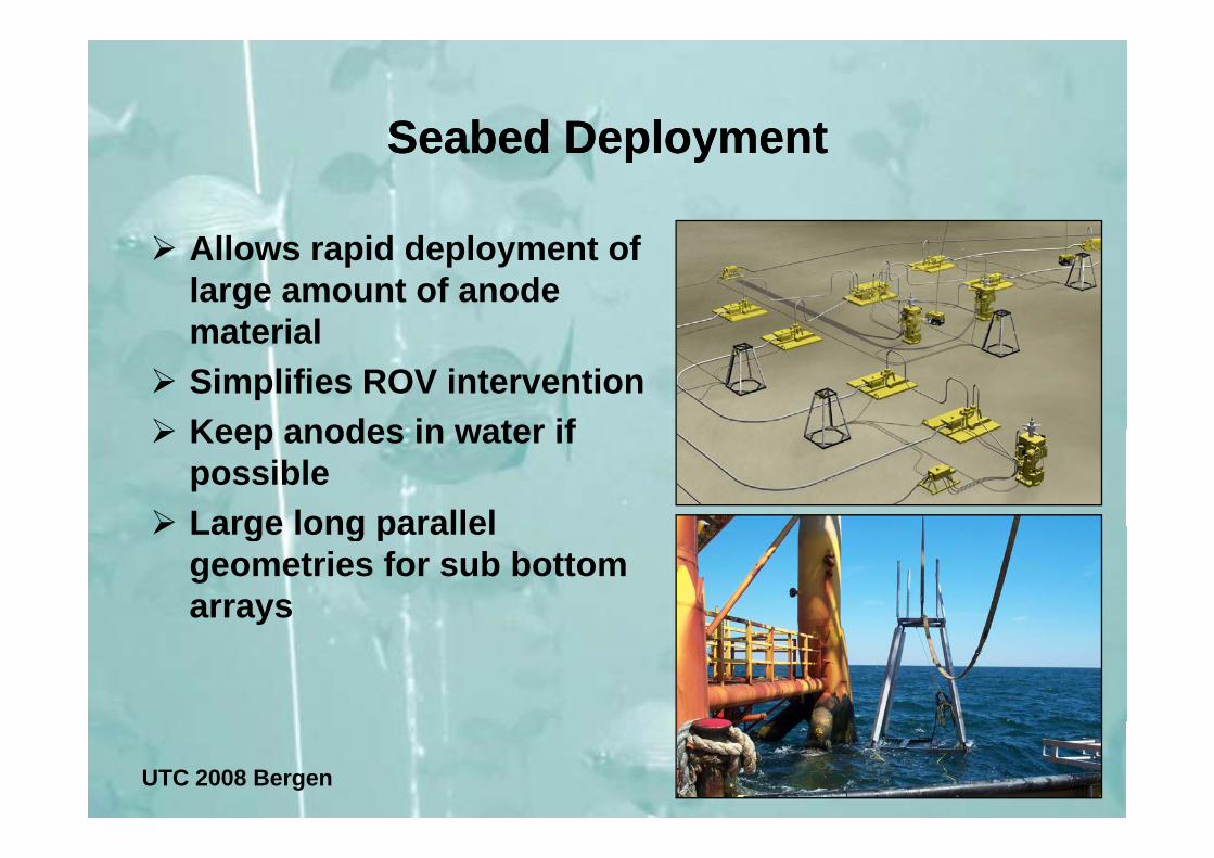
Seabed DeploymentSeabed DeploymentSeabed Deployment Seabed Deployment
Allows rapid deployment of large amount of anode materialmaterialSimplifies ROV interventionKeep anodes in water ifKeep anodes in water if possibleLarge long parallelLarge long parallel geometries for sub bottom arraysy
UTC 2008 Bergen © Deepwater Corrosion Services Inc. 2008
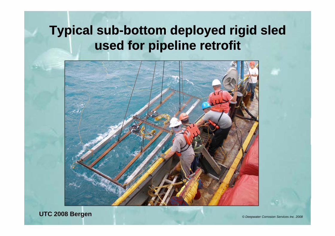
Typical subTypical sub--bottom deployed rigid sled bottom deployed rigid sled used for pipeline retrofitused for pipeline retrofit
UTC 2008 Bergen © Deepwater Corrosion Services Inc. 2008
TieTie Back SystemsBack SystemsTieTie--Back SystemsBack SystemsThe electro-mechanical connection between the anode array and the structure is critical
Connect fails ! CP system fails!Must be ROV friendly
OptionsMechanical clamp
Generally favored by most operators based on cost andGenerally favored by most operators based on cost and reliability
Friction WeldingExpensive and tough to controlExpensive and tough to control
Explosive StudsDifficult for ROV, not suited to pipelines
Wet WeldingOperators tend to shy away – very difficult for ROV
UTC 2008 Bergen © Deepwater Corrosion Services Inc. 2008
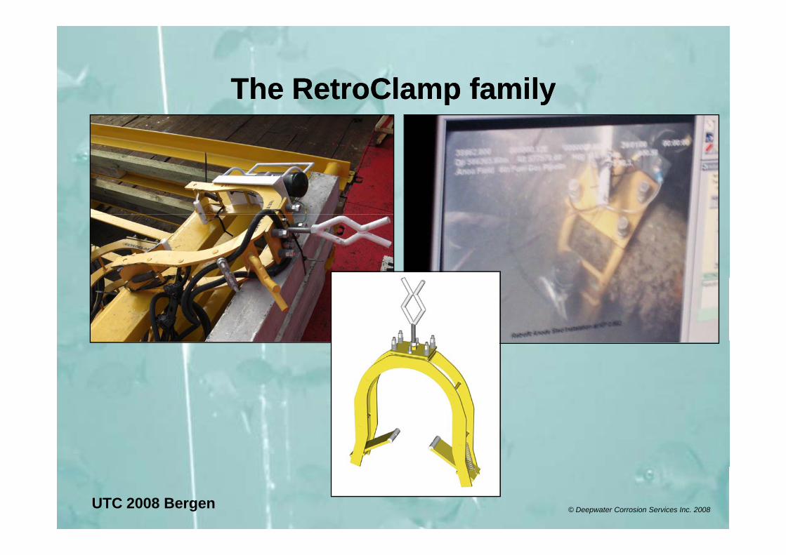
The RetroClamp familyThe RetroClamp familyThe RetroClamp familyThe RetroClamp family
UTC 2008 Bergen © Deepwater Corrosion Services Inc. 2008
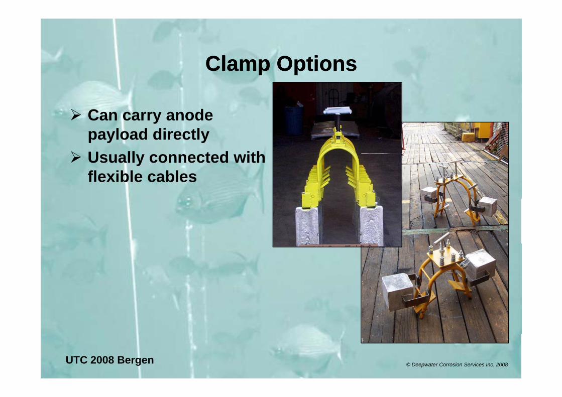
Clamp OptionsClamp OptionsClamp OptionsClamp Options
Can carry anode payload directlyU ll t d ithUsually connected with flexible cables
UTC 2008 Bergen © Deepwater Corrosion Services Inc. 2008
Tieback Clamp Design FeaturesTieback Clamp Design FeaturesTieback Clamp Design FeaturesTieback Clamp Design Features
Range of configurations have been used they all have common features.
Single action easy location onto targetSingle action easy location onto targetHolding mechanism to hold position while torque is appliedContact element held with constant tensionVariety of contact tips for connection to
StructuralPi li / PPipeline / ProcessPipelines with coating variables
UTC 2008 Bergen © Deepwater Corrosion Services Inc. 2008
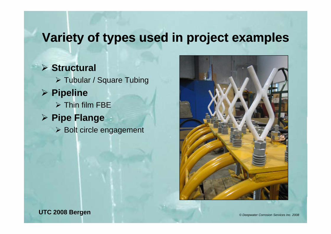
Variety of types used in project examplesVariety of types used in project examplesVariety of types used in project examplesVariety of types used in project examples
StructuralTubular / Square Tubing
Pi liPipelineThin film FBE
Pipe FlangePipe FlangeBolt circle engagement
UTC 2008 Bergen © Deepwater Corrosion Services Inc. 2008
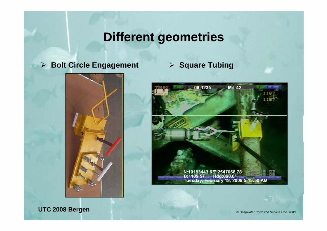
Different geometriesDifferent geometriesDifferent geometriesDifferent geometries
B lt Ci l E t S T biBolt Circle Engagement Square Tubing
UTC 2008 Bergen © Deepwater Corrosion Services Inc. 2008
Verification / MonitoringVerification / MonitoringVerification / MonitoringVerification / Monitoring
Temporary installation readerIndicates clamp contact
P t itPermanent monitorsShow anode current or potential shift
Portable ProbesPortable ProbesBefore / after measurement
UTC 2008 Bergen © Deepwater Corrosion Services Inc. 2008
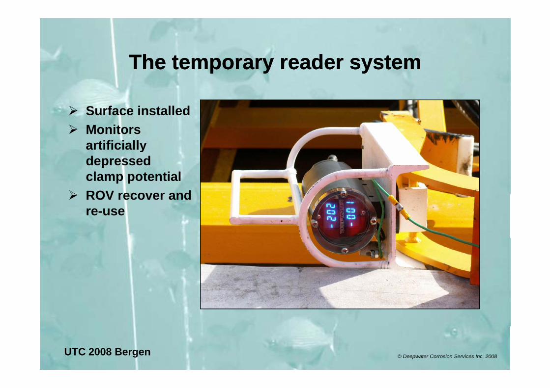
The temporary reader systemThe temporary reader systemThe temporary reader systemThe temporary reader system
S f i ll dSurface installedMonitors artificially ydepressed clamp potentialROV recover andROV recover and re-use
UTC 2008 Bergen © Deepwater Corrosion Services Inc. 2008
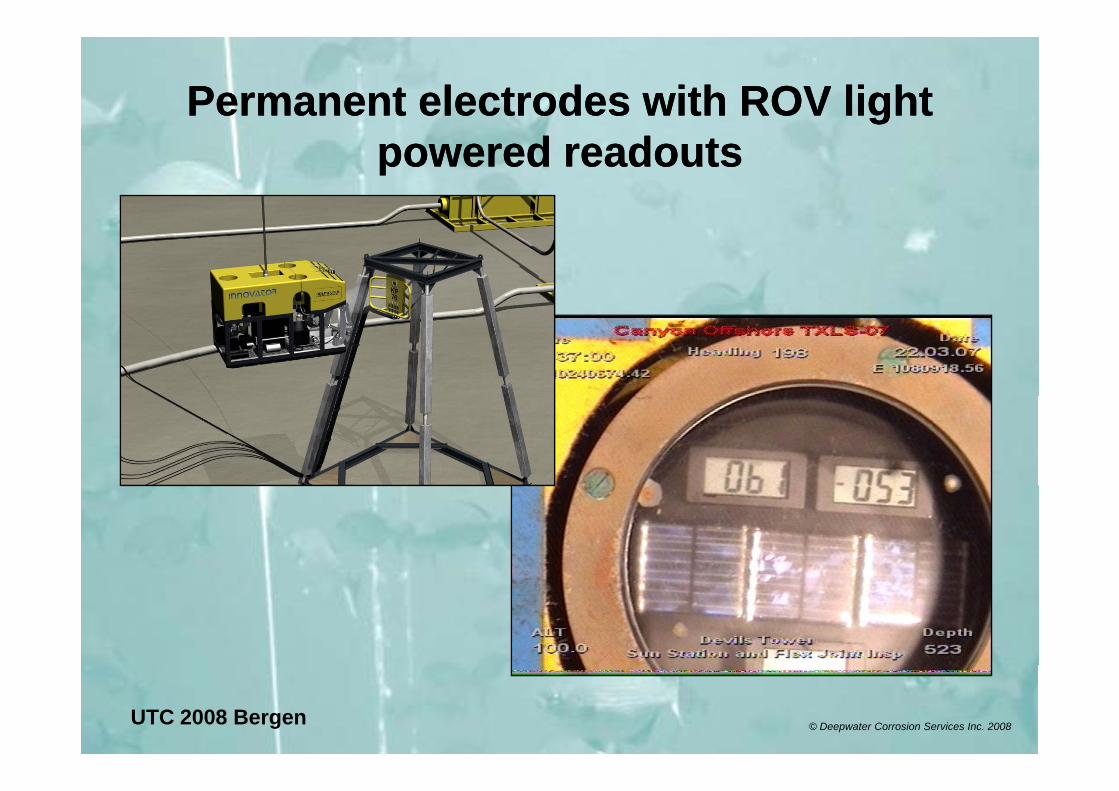
Permanent electrodes with ROV light Permanent electrodes with ROV light powered readoutspowered readouts
UTC 2008 Bergen © Deepwater Corrosion Services Inc. 2008
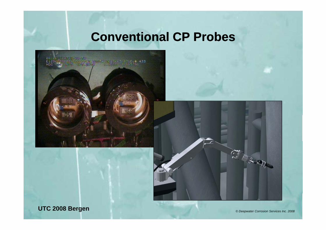
Conventional CP ProbesConventional CP ProbesConventional CP ProbesConventional CP Probes
UTC 2008 Bergen © Deepwater Corrosion Services Inc. 2008
Project AProject A N North Sea 2007N North Sea 2007Project A Project A –– N. North Sea 2007N. North Sea 2007
150 MetersReason for Retrofit
Pipelines showing advanced anode depletion, draining CP to platform jackets. Pipeline boost required.
Scale of RetrofitScale of Retrofit17 Anode arrays – 34 tiebacks10 Pods 7 Sleds4 locations CWC removal
ROV’s 2 x Triton WC / 1 Seaeye Tiger ICOffshore Retrofit Duration 238 HrsAverage / Array 14 Hrs.
UTC 2008 Bergen © Deepwater Corrosion Services Inc. 2008
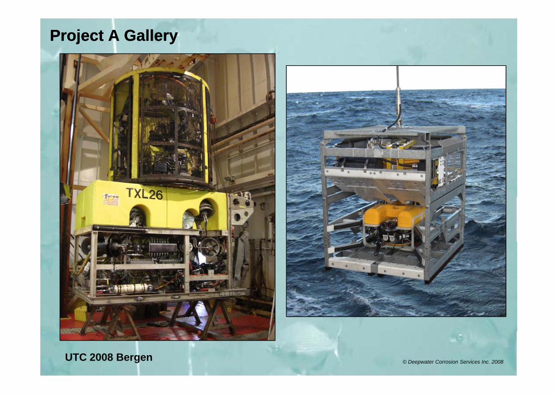
Project A GalleryProject A Gallery
UTC 2008 Bergen © Deepwater Corrosion Services Inc. 2008
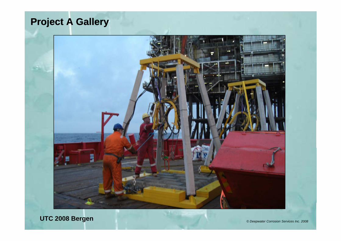
Project A GalleryProject A Gallery
UTC 2008 Bergen © Deepwater Corrosion Services Inc. 2008
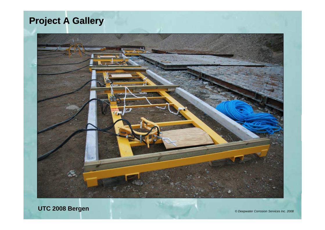
Project A GalleryProject A Gallery
UTC 2008 Bergen © Deepwater Corrosion Services Inc. 2008
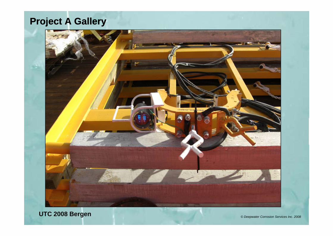
Project A GalleryProject A Gallery
UTC 2008 Bergen © Deepwater Corrosion Services Inc. 2008
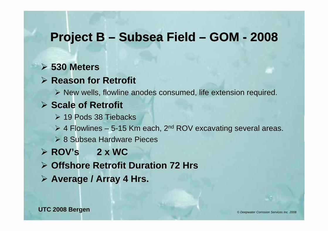
Project BProject B Subsea FieldSubsea Field GOMGOM 20082008Project B Project B –– Subsea Field Subsea Field –– GOM GOM -- 20082008
530 MetersReason for Retrofit
New wells, flowline anodes consumed, life extension required.
Scale of Retrofit19 Pods 38 Tiebacks19 Pods 38 Tiebacks4 Flowlines – 5-15 Km each, 2nd ROV excavating several areas.8 Subsea Hardware Pieces8 Subsea Hardware Pieces
ROV’s 2 x WCOffshore Retrofit Duration 72 HrsOffshore Retrofit Duration 72 HrsAverage / Array 4 Hrs.
UTC 2008 Bergen © Deepwater Corrosion Services Inc. 2008
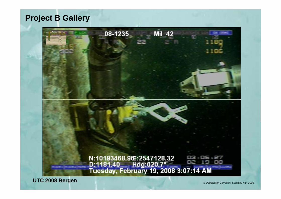
Project B GalleryProject B Gallery
UTC 2008 Bergen © Deepwater Corrosion Services Inc. 2008

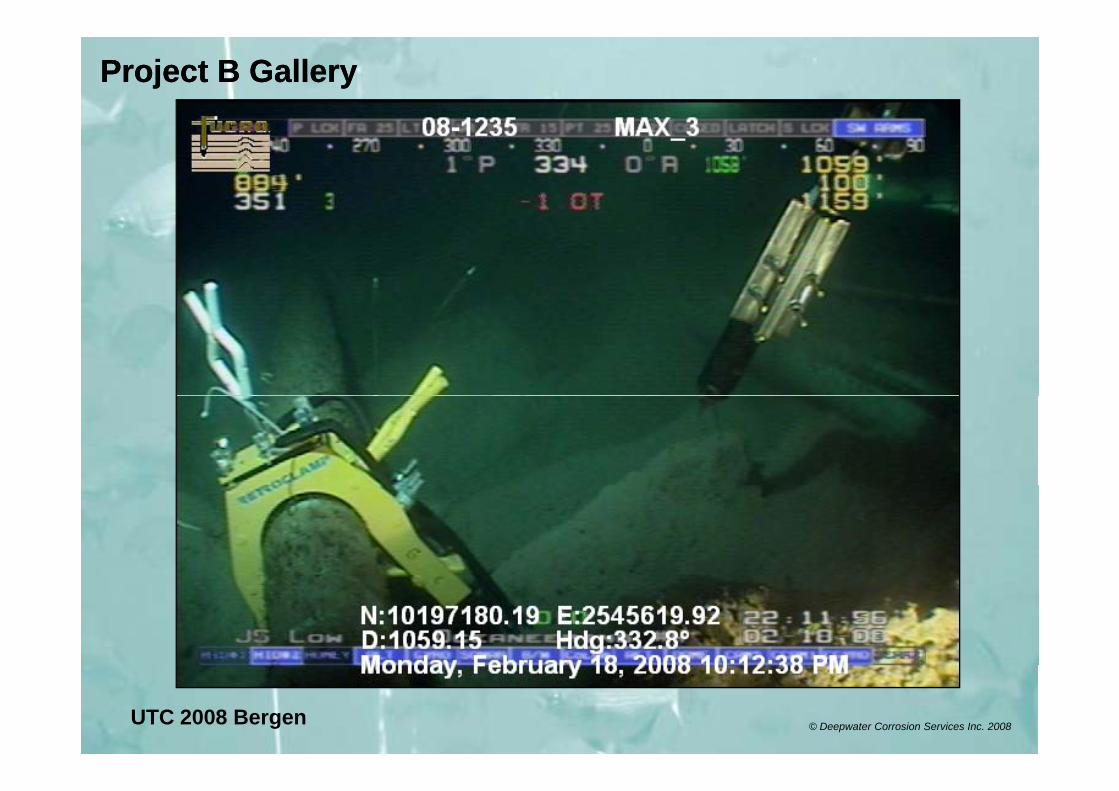
Project B GalleryProject B Gallery
UTC 2008 Bergen © Deepwater Corrosion Services Inc. 2008
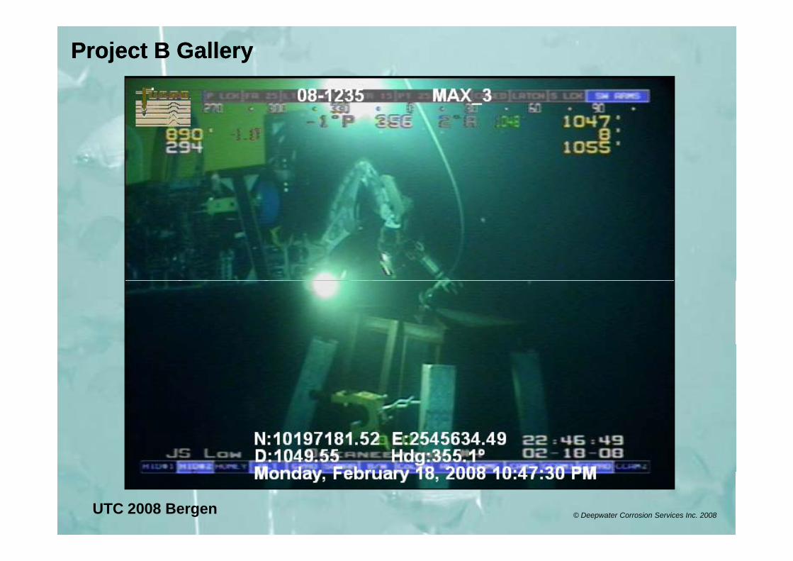
Project B GalleryProject B Gallery
UTC 2008 Bergen © Deepwater Corrosion Services Inc. 2008
Project B GalleryProject B Gallery
UTC 2008 Bergen © Deepwater Corrosion Services Inc. 2008
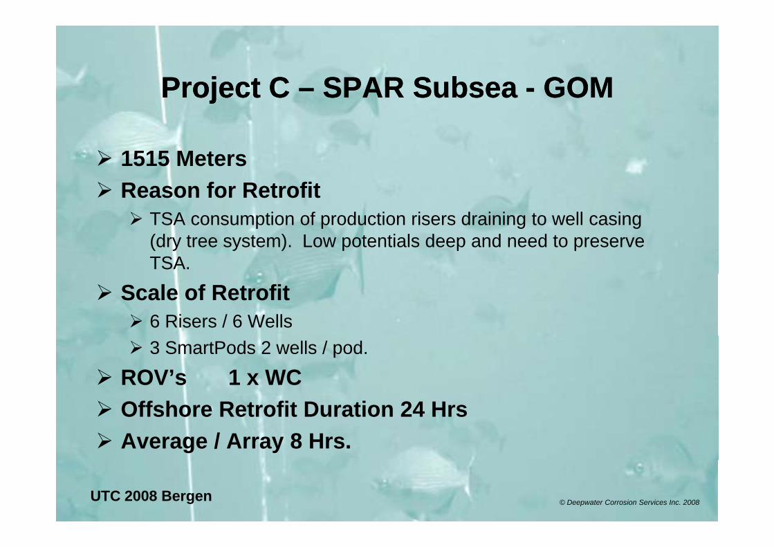
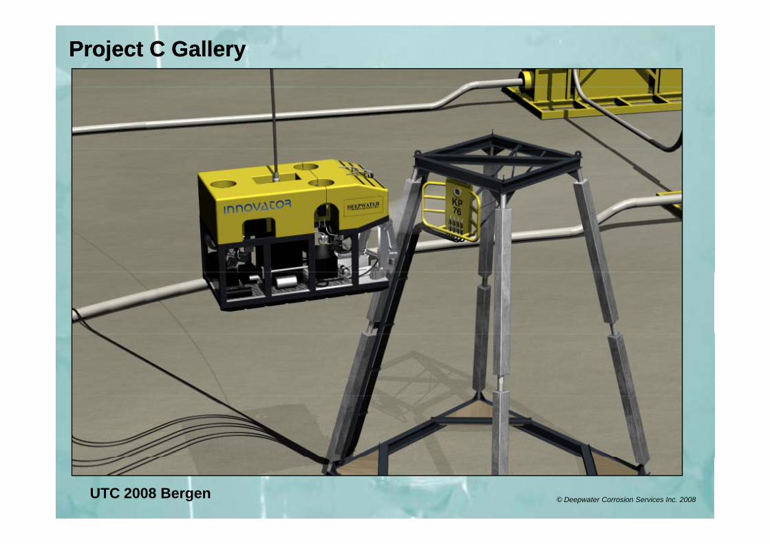
Project CProject C SPAR SubseaSPAR Subsea GOMGOMProject C Project C –– SPAR Subsea SPAR Subsea -- GOMGOM
1515 MetersReason for Retrofit
TSA consumption of production risers draining to well casing (dry tree system). Low potentials deep and need to preserve TSA.
Scale of Retrofit6 Risers / 6 Wells 3 SmartPods 2 wells / pod.
ROV’s 1 x WCOffshore Retrofit Duration 24 HrsAverage / Array 8 Hrs.
UTC 2008 Bergen © Deepwater Corrosion Services Inc. 2008
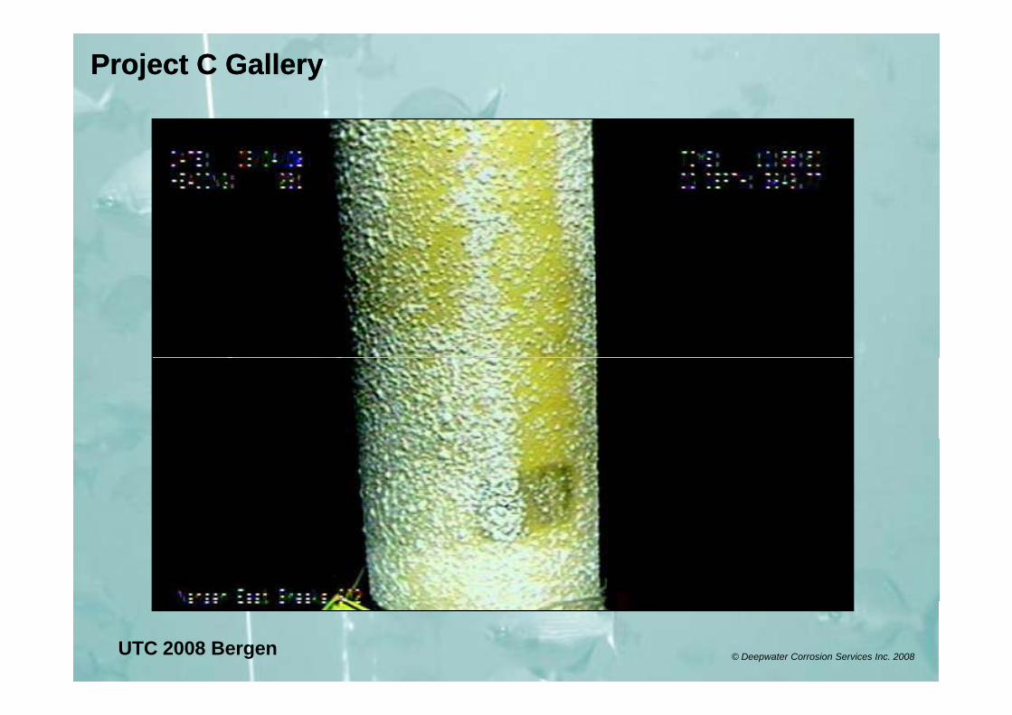
Project C GalleryProject C Gallery
UTC 2008 Bergen © Deepwater Corrosion Services Inc. 2008
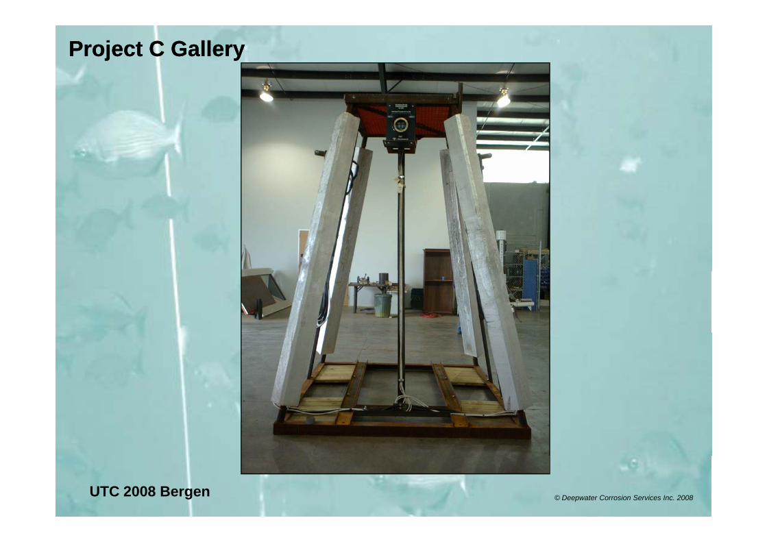
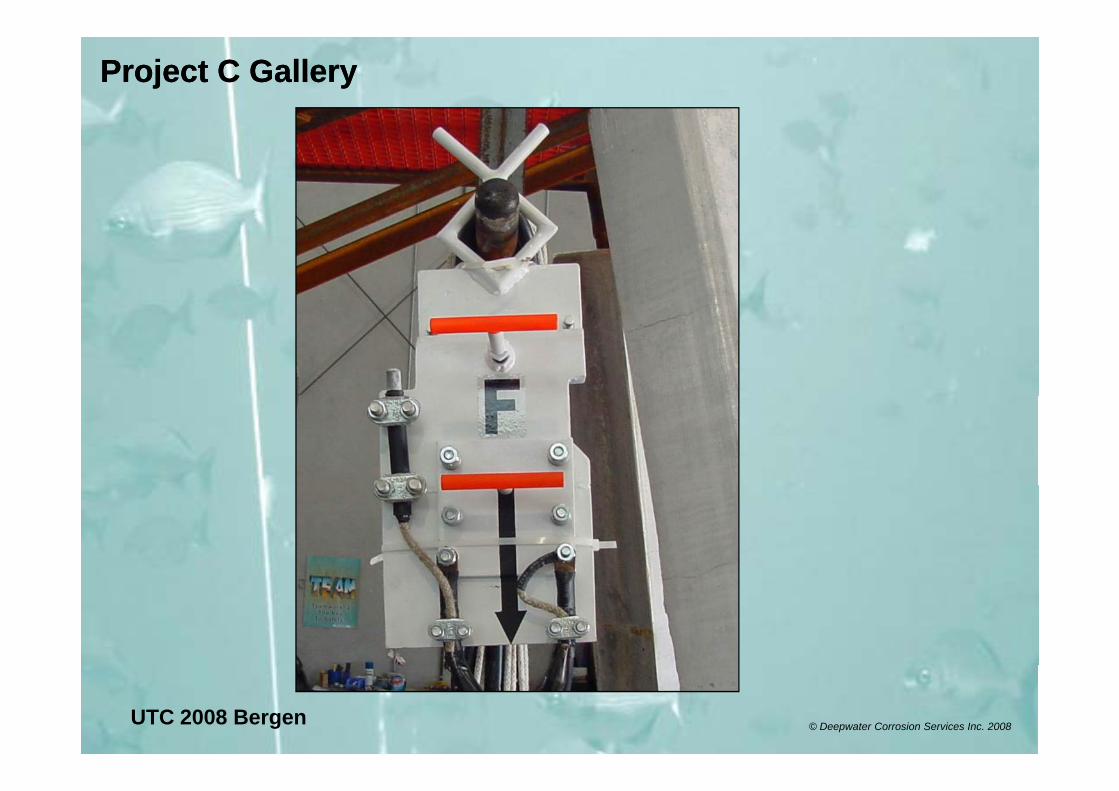
Project C GalleryProject C Gallery
UTC 2008 Bergen © Deepwater Corrosion Services Inc. 2008
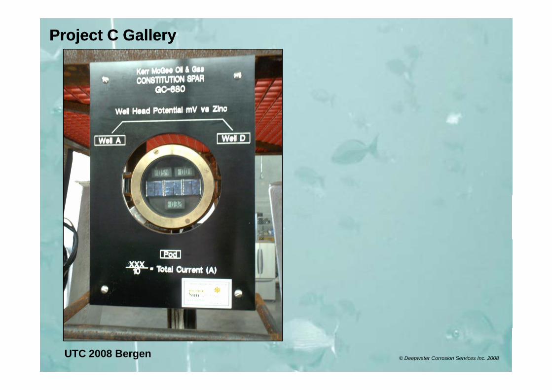
Project C GalleryProject C Gallery
UTC 2008 Bergen © Deepwater Corrosion Services Inc. 2008
Project C GalleryProject C Gallery
UTC 2008 Bergen © Deepwater Corrosion Services Inc. 2008
Project C GalleryProject C Gallery
UTC 2008 Bergen © Deepwater Corrosion Services Inc. 2008
Summary & ConclusionsSummary & ConclusionsSummary & ConclusionsSummary & Conclusions
ROV can be very efficient at anode retrofitProject planning criticalUse proven hardware solutionsUse proven hardware solutions
As this type of maintenance becomes second nature new equipment can go safely to post installed CPnew equipment can go safely to post installed CP.
UTC 2008 Bergen © Deepwater Corrosion Services Inc. 2008
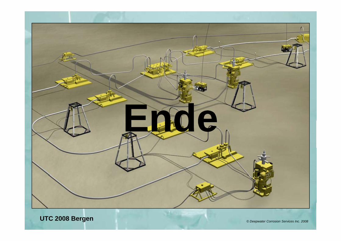
EndeEndeEndeEnde
UTC 2008 Bergen © Deepwater Corrosion Services Inc. 2008


![Computational modelling of cathodic protection …...Laplacian equations and in particular simulate cathodic protection systems for underground and offshore structures [2–4]. The](https://img.pdfslide.net/doc/110x75/5f6d8a4a7302ab55cb5fc00a/computational-modelling-of-cathodic-protection-laplacian-equations-and-in-particular.jpg)