Embed Size (px)
Citation preview
Smart-UPS™On-Line Isolation and Step-Down Transformer SRT10KRMTF
Safety MessagesRead the instructions carefully to become familiar with the equipment before attempting to install, operate, service or maintain the transformer. The following special messages may appear throughout this manual or on the equipment to warn of potential hazards or to call attention to information that clarifies or simplifies a procedure.
The addition of this symbol to a Danger or Warning safety label indicates that an electrical hazard exists which will result in personal injury if the instructions are not followed.
The addition of this symbol to a Warning or Caution product safety label indicates that a hazard exists that can result in injury and product damage if the instructions are not followed.
Information
Safety Information• Adhere to all national and local electrical codes.
• All wiring must be performed by a qualified electrician.
• Changes and modifications to this unit not expressly approved by APC by Schneider Electric could void the warranty.
• This transformer is intended for indoor use only.
• Do not operate this transformer in direct sunlight, in contact with fluids, or where there is excessive dust or humidity.
• Be sure the air vents on the transformer are not blocked. Allow adequate space for proper ventilation.
• For a transformer with a factory installed power cord, connect the transformer power cable directly to an output receptacle of the UPS. Do not use surge protectors or extension cords.
• The equipment is heavy. Always practice safe lifting techniques adequate for the weight of the equipment.
• For rack mount transformers, always install the transformer directly above the UPS in rack-mount configurations. The UPS must be installed below the transformer.
• Always install peripheral equipment above the UPS in rack-mount configurations.
• Additional safety information can be found in the Safety Guide supplied with this unit.
CAUTION
CAUTION indicates a potentially hazardous situation which, if not avoided, can result in minor or moderate injury.
CAUTION
CAUTION addresses practices not related to physical injury including certain environmental hazards, potential damage or loss of data.
Electrical safety
• For models with a hardwired input, the connection to the branch circuit (mains) must be performed by a qualified electrician.
• 230 V models only: In order to maintain compliance with the EMC directive for products sold in Europe, output cords attached to the transformer must not exceed 10 meters in length.
• The protective earth conductor for the transformer carries the leakage current from the load devices (computer equipment). An insulated ground conductor is to be installed as part of the branch circuit that supplies the transformer. The conductor must have the same size and insulation material as the grounded and ungrounded branch circuit supply conductors. The conductor will typically be green and with or without a yellow stripe.
• The UPS input ground conductor must be properly bonded to protective earth at the service panel.
• If the UPS input power is supplied by a separately derived system, the ground conductor must be properly bonded at the supply transformer or motor generator set.
Hardwire safety
• Verify that all branch circuit (mains) and low voltage (control) circuits are deenergized, and locked out before installing cables or making connections, whether in the junction box or to the transformer.
• Wiring by a qualified electrician is required.
• Check national and local codes before wiring.
• All openings that allow access to transformer hardwire terminals must be covered. Failure to do so may result in personal injury or equipment damage.
• Select wire size and connectors according to national and local codes.
General information
• The model and serial numbers are located on a small, rear panel label. For some models, an additional label is located on the chassis under the front bezel.
• Recycle the package materials or save them for reuse.
FCC Class A radio frequency warning
This equipment has been tested and found to comply with the limits for a Class A digital device, pursuant to part 15 of the FCC Rules. These limits are intended to provide reasonable protection against harmful interference when the equipment is operated in a commercial environment. This equipment generates, uses, and can radiate radio frequency energy and, if not installed and used in accordance with the instruction manual, may cause harmful interference to radio communications. Operation of this equipment in a residential area is likely to cause harmful interference in which case the user will be required to correct the interference at his own expense.
Product InformationThe Smart-UPS™ SRT transformer is intended for use as an isolation transformer. This transformer can also function as a step down transformer.
The transformer can be installed in a standard 19-inch rack with the supplied rail kit.
Isolation and Step-Down Transformer SRT10KRMTF2
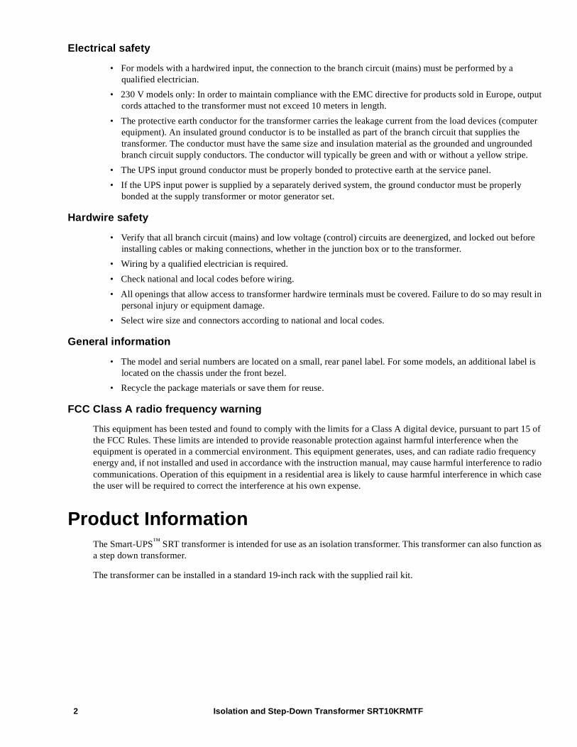
Package ContentsInspect the contents upon receipt. Notify the carrier and dealer if the unit is damaged.
SpecificationsFor additional specifications refer to the APC by Schneider Electric web site, www.apc.com.
Environmental
2 front bezels 1 tie bracket
2 screws to secure tie bracket
2 tie brackets
1 pair rack-mount brackets8 flat head screws
1 pair rail cleats4 pan head screws
Communication cable
2 pairs stabilizer brackets 4 handles
TemperatureOperating 0º to 40º C (32º to 104º F)
Storage -15º to 45º C (5º to 113º F)
Maximum ElevationOperating 0 - 3,000 m (0 - 10,000 ft)
Storage 0 - 15,000 m (0 - 50,000 ft)
Humidity 0% to 95% relative humidity, non-condensing
Protection Class IP 20 rating
x8
x4
Isolation and Step-Down Transformer SRT10KRMTF 3
Isolation and Step-Down Transformer SRT10KRMTF4
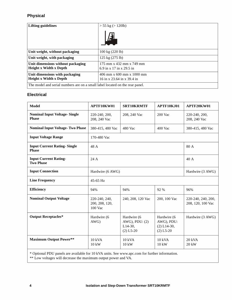
Physical
Electrical
Lifting guidelines > 55 kg (> 120lb)
Unit weight, without packaging 100 kg (220 lb)
Unit weight, with packaging 125 kg (275 lb)
Unit dimensions without packagingHeight x Width x Depth
175 mm x 432 mm x 749 mm6.9 in x 17 in x 29.5 in
Unit dimensions with packagingHeight x Width x Depth
406 mm x 600 mm x 1000 mm16 in x 23.64 in x 39.4 in
The model and serial numbers are on a small label located on the rear panel.
Model APTF10KW01 SRT10KRMTF APTF10KJ01 APTF20KW01
Nominal Input Voltage- Single Phase
220-240, 200, 208, 240 Vac
208, 240 Vac 200 Vac 220-240, 200, 208, 240 Vac
Nominal Input Voltage- Two Phase 380-415, 480 Vac 480 Vac 400 Vac 380-415, 480 Vac
Input Voltage Range 170-480 Vac
Input Current Rating- Single Phase
48 A 80 A
Input Current Rating-Two Phase
24 A 40 A
Input Connection Hardwire (6 AWG) Hardwire (3 AWG)
Line Frequency 45-65 Hz
Efficiency 94% 94% 92 % 96%
Nominal Output Voltage 220-240, 240, 200, 208, 120, 100 Vac
240, 208, 120 Vac 200, 100 Vac 220-240, 240, 200, 208, 120, 100 Vac
Output Receptacles* Hardwire (6 AWG)
Hardwire (6 AWG), PDU: (2) L14-30, (2) L5-20
Hardwire (6 AWG), PDU: (2) L14-30,(2) L5-20
Hardwire (3 AWG)
Maximum Output Power** 10 kVA10 kW
10 kVA10 kW
10 kVA10 kW
20 kVA20 kW
* Optional PDU panels are available for 10 kVA units. See www.apc.com for further information.** Low voltages will decrease the maximum output power and VA.
Isolation and Step-Down Transformer SRT10KRMTF 5
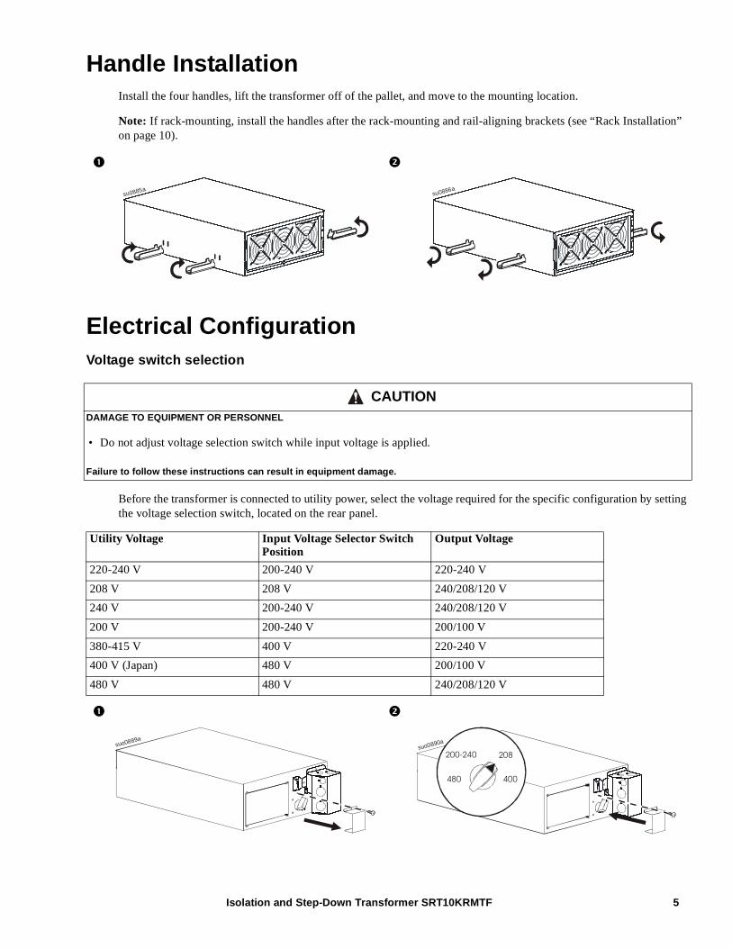
Handle InstallationInstall the four handles, lift the transformer off of the pallet, and move to the mounting location.
Note: If rack-mounting, install the handles after the rack-mounting and rail-aligning brackets (see “Rack Installation” on page 10).
Electrical ConfigurationVoltage switch selection
Before the transformer is connected to utility power, select the voltage required for the specific configuration by setting the voltage selection switch, located on the rear panel.
CAUTIONDAMAGE TO EQUIPMENT OR PERSONNEL
• Do not adjust voltage selection switch while input voltage is applied.
Failure to follow these instructions can result in equipment damage.
Utility Voltage Input Voltage Selector Switch Position
Output Voltage
220-240 V 200-240 V 220-240 V
208 V 208 V 240/208/120 V
240 V 200-240 V 240/208/120 V
200 V 200-240 V 200/100 V
380-415 V 400 V 220-240 V
400 V (Japan) 480 V 200/100 V
480 V 480 V 240/208/120 V
su0885asu0886a
suo0889a
480
200-240 208
400
suo0890a
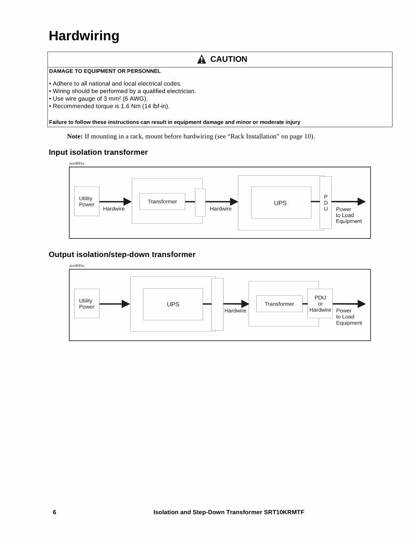
Hardwiring
Note: If mounting in a rack, mount before hardwiring (see “Rack Installation” on page 10).
Input isolation transformer
Output isolation/step-down transformer
CAUTIONDAMAGE TO EQUIPMENT OR PERSONNEL
• Adhere to all national and local electrical codes.• Wiring should be performed by a qualified electrician.• Use wire gauge of 3 mm² (6 AWG).• Recommended torque is 1.6 Nm (14 lbf-in).
Failure to follow these instructions can result in equipment damage and minor or moderate injury
UtilityPower
Hardwire HardwireTransformer
PDU
UPS
suo0891a
UtilityPower
Hardwire Powerto Load Equipment
TransformerPDU
orHardwire
UPS
suo0892a
Isolation and Step-Down Transformer SRT10KRMTF6
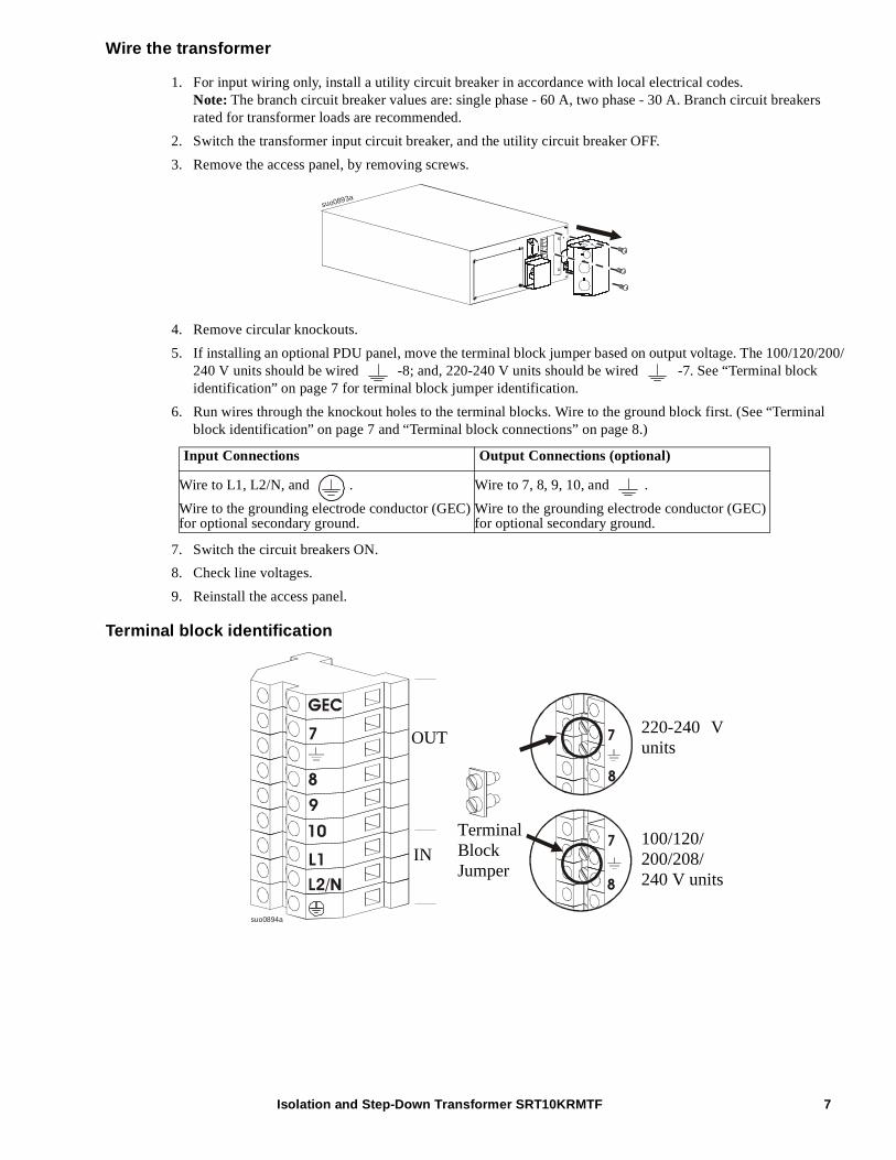
Wire the transformer
1. For input wiring only, install a utility circuit breaker in accordance with local electrical codes.Note: The branch circuit breaker values are: single phase - 60 A, two phase - 30 A. Branch circuit breakers rated for transformer loads are recommended.
2. Switch the transformer input circuit breaker, and the utility circuit breaker OFF.
3. Remove the access panel, by removing screws.
4. Remove circular knockouts.
5. If installing an optional PDU panel, move the terminal block jumper based on output voltage. The 100/120/200/240 V units should be wired -8; and, 220-240 V units should be wired -7. See “Terminal block identification” on page 7 for terminal block jumper identification.
6. Run wires through the knockout holes to the terminal blocks. Wire to the ground block first. (See “Terminal block identification” on page 7 and “Terminal block connections” on page 8.)
7. Switch the circuit breakers ON.
8. Check line voltages.
9. Reinstall the access panel.
Terminal block identification
Input Connections Output Connections (optional)
Wire to L1, L2/N, and .
Wire to the grounding electrode conductor (GEC) for optional secondary ground.
Wire to 7, 8, 9, 10, and .
Wire to the grounding electrode conductor (GEC) for optional secondary ground.
suo0893a
8
7
7
8
suo0894a
7
8
9
10
L1100/120/200/208/240 V units
220-240 Vunits
TerminalBlockJumper
OUT
IN
Isolation and Step-Down Transformer SRT10KRMTF 7
Isolation and Step-Down Transformer SRT10KRMTF8
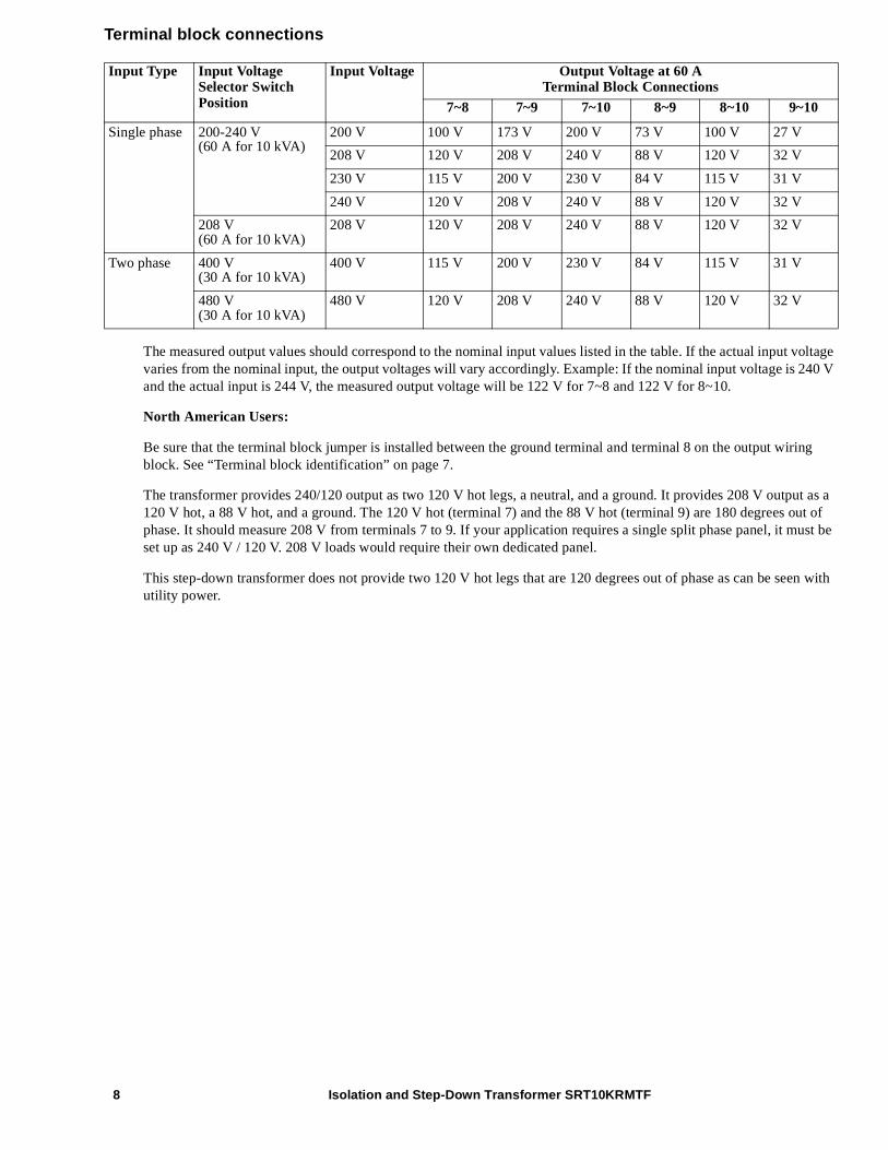
Terminal block connections
The measured output values should correspond to the nominal input values listed in the table. If the actual input voltage varies from the nominal input, the output voltages will vary accordingly. Example: If the nominal input voltage is 240 V and the actual input is 244 V, the measured output voltage will be 122 V for 7~8 and 122 V for 8~10.
North American Users:
Be sure that the terminal block jumper is installed between the ground terminal and terminal 8 on the output wiring block. See “Terminal block identification” on page 7.
The transformer provides 240/120 output as two 120 V hot legs, a neutral, and a ground. It provides 208 V output as a 120 V hot, a 88 V hot, and a ground. The 120 V hot (terminal 7) and the 88 V hot (terminal 9) are 180 degrees out of phase. It should measure 208 V from terminals 7 to 9. If your application requires a single split phase panel, it must be set up as 240 V / 120 V. 208 V loads would require their own dedicated panel.
This step-down transformer does not provide two 120 V hot legs that are 120 degrees out of phase as can be seen with utility power.
Input Type Input Voltage Selector Switch Position
Input Voltage Output Voltage at 60 ATerminal Block Connections
7~8 7~9 7~10 8~9 8~10 9~10
Single phase 200-240 V(60 A for 10 kVA)
200 V 100 V 173 V 200 V 73 V 100 V 27 V
208 V 120 V 208 V 240 V 88 V 120 V 32 V
230 V 115 V 200 V 230 V 84 V 115 V 31 V
240 V 120 V 208 V 240 V 88 V 120 V 32 V
208 V(60 A for 10 kVA)
208 V 120 V 208 V 240 V 88 V 120 V 32 V
Two phase 400 V(30 A for 10 kVA)
400 V 115 V 200 V 230 V 84 V 115 V 31 V
480 V(30 A for 10 kVA)
480 V 120 V 208 V 240 V 88 V 120 V 32 V
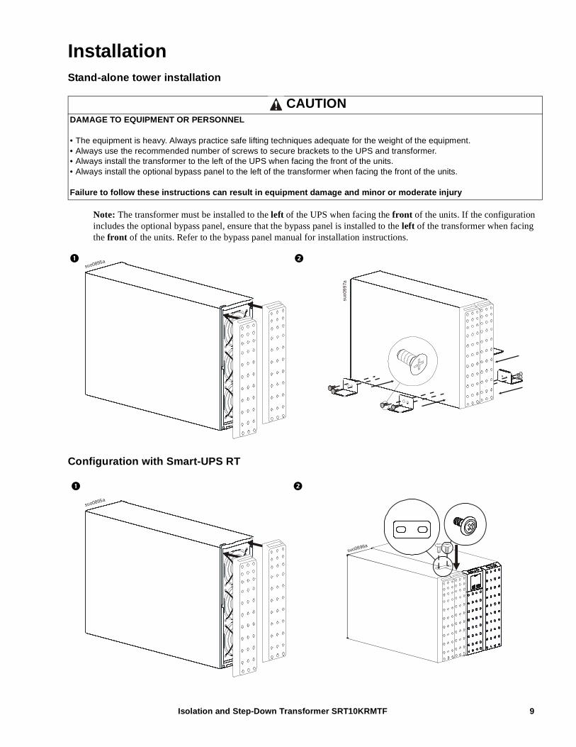
InstallationStand-alone tower installation
Note: The transformer must be installed to the left of the UPS when facing the front of the units. If the configuration includes the optional bypass panel, ensure that the bypass panel is installed to the left of the transformer when facing the front of the units. Refer to the bypass panel manual for installation instructions.
Configuration with Smart-UPS RT
CAUTIONDAMAGE TO EQUIPMENT OR PERSONNEL
• The equipment is heavy. Always practice safe lifting techniques adequate for the weight of the equipment.• Always use the recommended number of screws to secure brackets to the UPS and transformer.• Always install the transformer to the left of the UPS when facing the front of the units.• Always install the optional bypass panel to the left of the transformer when facing the front of the units.
Failure to follow these instructions can result in equipment damage and minor or moderate injury
suo0895a
suo
099
7a
suo0895a
suo0896a
Isolation and Step-Down Transformer SRT10KRMTF 9
Isolation and Step-Down Transformer SRT10KRMTF10
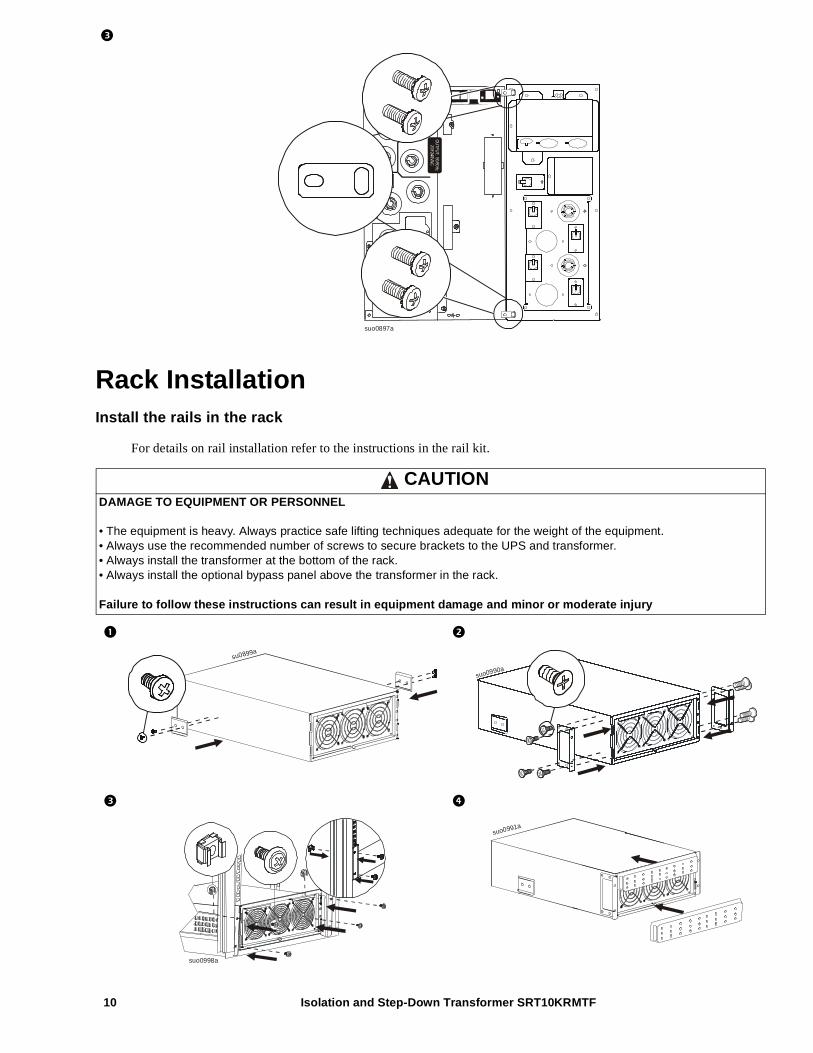
Rack InstallationInstall the rails in the rack
For details on rail installation refer to the instructions in the rail kit.
CAUTIONDAMAGE TO EQUIPMENT OR PERSONNEL
• The equipment is heavy. Always practice safe lifting techniques adequate for the weight of the equipment.• Always use the recommended number of screws to secure brackets to the UPS and transformer.• Always install the transformer at the bottom of the rack.• Always install the optional bypass panel above the transformer in the rack.
Failure to follow these instructions can result in equipment damage and minor or moderate injury
GROUP 120 AMP MAX
GROUP 220 AMP MAX
GROUP 330 AM
P MAX
suo0897a
su0899a
suo0990a
suo0998a
suo0991a
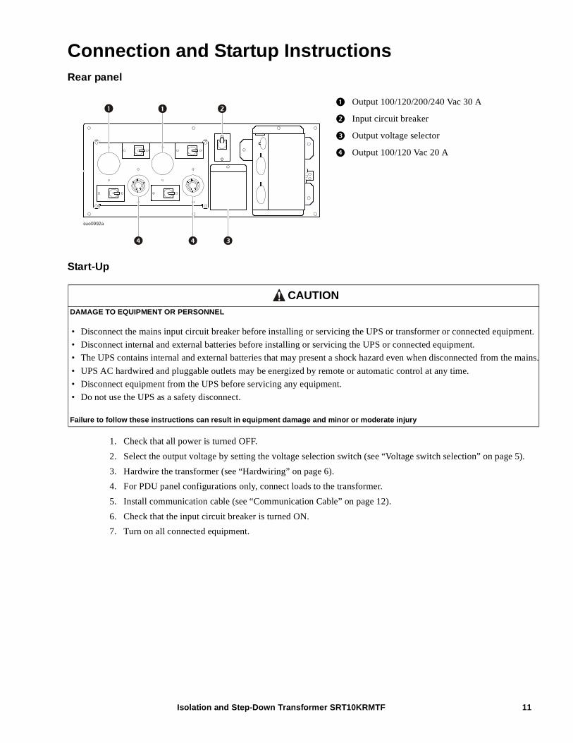
Connection and Startup InstructionsRear panel
Start-Up
1. Check that all power is turned OFF.
2. Select the output voltage by setting the voltage selection switch (see “Voltage switch selection” on page 5).
3. Hardwire the transformer (see “Hardwiring” on page 6).
4. For PDU panel configurations only, connect loads to the transformer.
5. Install communication cable (see “Communication Cable” on page 12).
6. Check that the input circuit breaker is turned ON.
7. Turn on all connected equipment.
Output 100/120/200/240 Vac 30 A
Input circuit breaker
Output voltage selector
Output 100/120 Vac 20 A
CAUTIONDAMAGE TO EQUIPMENT OR PERSONNEL
• Disconnect the mains input circuit breaker before installing or servicing the UPS or transformer or connected equipment.
• Disconnect internal and external batteries before installing or servicing the UPS or connected equipment.
• The UPS contains internal and external batteries that may present a shock hazard even when disconnected from the mains.
• UPS AC hardwired and pluggable outlets may be energized by remote or automatic control at any time.
• Disconnect equipment from the UPS before servicing any equipment.
• Do not use the UPS as a safety disconnect.
Failure to follow these instructions can result in equipment damage and minor or moderate injury
suo0992a
Isolation and Step-Down Transformer SRT10KRMTF 11
Isolation and Step-Down Transformer SRT10KRMTF12
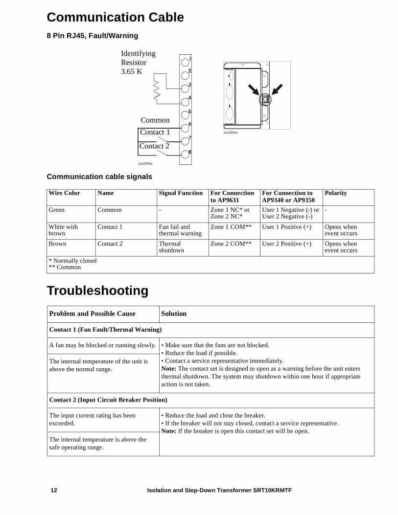
Communication Cable8 Pin RJ45, Fault/Warning
Communication cable signals
Troubleshooting
Wire Color Name Signal Function For Connection to AP9631
For Connection to AP9340 or AP9350
Polarity
Green Common - Zone 1 NC* or Zone 2 NC*
User 1 Negative (-) or User 2 Negative (-)
-
White with brown
Contact 1 Fan fail and thermal warning
Zone 1 COM** User 1 Positive (+) Opens when event occurs
Brown Contact 2 Thermal shutdown
Zone 2 COM** User 2 Positive (+) Opens when event occurs
* Normally closed** Common
Problem and Possible Cause Solution
Contact 1 (Fan Fault/Thermal Warning)
A fan may be blocked or running slowly. • Make sure that the fans are not blocked.• Reduce the load if possible.• Contact a service representative immediately.Note: The contact set is designed to open as a warning before the unit enters thermal shutdown. The system may shutdown within one hour if appropriate action is not taken.
The internal temperature of the unit is above the normal range.
Contact 2 (Input Circuit Breaker Position)
The input current rating has been exceeded.
• Reduce the load and close the breaker.• If the breaker will not stay closed, contact a service representative.Note: If the breaker is open this contact set will be open.
The internal temperature is above the safe operating range.
1
8
7
6
5
4
3
2
suo0993a
IdentifyingResistor3.65 K
Common
Contact 1
Contact 2
suo0994a
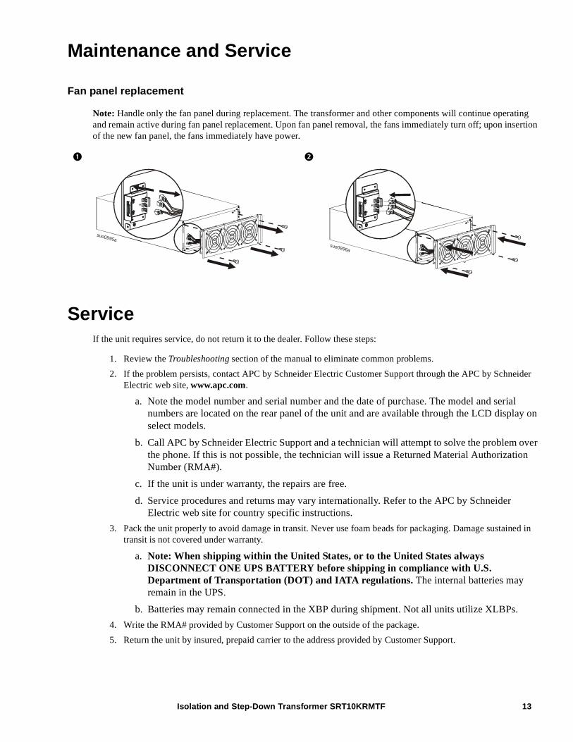
Maintenance and Service
Fan panel replacement
Note: Handle only the fan panel during replacement. The transformer and other components will continue operating and remain active during fan panel replacement. Upon fan panel removal, the fans immediately turn off; upon insertion of the new fan panel, the fans immediately have power.
ServiceIf the unit requires service, do not return it to the dealer. Follow these steps:
1. Review the Troubleshooting section of the manual to eliminate common problems.
2. If the problem persists, contact APC by Schneider Electric Customer Support through the APC by Schneider Electric web site, www.apc.com.
a. Note the model number and serial number and the date of purchase. The model and serial numbers are located on the rear panel of the unit and are available through the LCD display on select models.
b. Call APC by Schneider Electric Support and a technician will attempt to solve the problem over the phone. If this is not possible, the technician will issue a Returned Material Authorization Number (RMA#).
c. If the unit is under warranty, the repairs are free.
d. Service procedures and returns may vary internationally. Refer to the APC by Schneider Electric web site for country specific instructions.
3. Pack the unit properly to avoid damage in transit. Never use foam beads for packaging. Damage sustained in transit is not covered under warranty.
a. Note: When shipping within the United States, or to the United States always DISCONNECT ONE UPS BATTERY before shipping in compliance with U.S. Department of Transportation (DOT) and IATA regulations. The internal batteries may remain in the UPS.
b. Batteries may remain connected in the XBP during shipment. Not all units utilize XLBPs.
4. Write the RMA# provided by Customer Support on the outside of the package.
5. Return the unit by insured, prepaid carrier to the address provided by Customer Support.
suo0995asuo0996a
Isolation and Step-Down Transformer SRT10KRMTF 13
Isolation and Step-Down Transformer SRT10KRMTF14
Limited Factory WarrantySchneider Electric IT Corporation (SEIT), warrants its products to be free from defects in materials and workmanship for a period of two (2) years from the date of purchase. The SEIT obligation under this warranty is limited to repairing or replacing, at its own sole option, any such defective products. Repair or replacement of a defective product or part thereof does not extend the original warranty period.
This warranty applies only to the original purchaser who must have properly registered the product within 10 days of purchase. Products may be registered online at warranty.apc.com.
SEIT shall not be liable under the warranty if its testing and examination disclose that the alleged defect in the product does not exist or was caused by end user or any third person misuse, negligence, improper installation, testing, operation or use of the product contrary to SEIT recommendations of specifications. Further, SEIT shall not be liable for defects resulting from: 1) unauthorized attempts to repair or modify the product, 2) incorrect or inadequate electrical voltage or connection, 3) inappropriate on site operation conditions, 4) Acts of God, 5) exposure to the elements, or 6) theft. In no event shall SEIT have any liability under this warranty for any product where the serial number has been altered, defaced, or removed.
EXCEPT AS SET FORTH ABOVE, THERE ARE NO WARRANTIES, EXPRESS OR IMPLIED, BY OPERATION OF LAW OR OTHERWISE, APPLICABLE TO PRODUCTS SOLD, SERVICED OR FURNISHED UNDER THIS AGREEMENT OR IN CONNECTION HEREWITH.
SEIT DISCLAIMS ALL IMPLIED WARRANTIES OF MERCHANTABILITY, SATISFACTION AND FITNESS FOR A PARTICULAR PURPOSE.
SEIT EXPRESS WARRANTIES WILL NOT BE ENLARGED, DIMINISHED, OR AFFECTED BY AND NO OBLIGATION OR LIABILITY WILL ARISE OUT OF, SEIT RENDERING OF TECHNICAL OR OTHER ADVICE OR SERVICE IN CONNECTION WITH THE PRODUCTS.
THE FOREGOING WARRANTIES AND REMEDIES ARE EXCLUSIVE AND IN LIEU OF ALL OTHER WARRANTIES AND REMEDIES. THE WARRANTIES SET FORTH ABOVE CONSTITUTE SEIT’S SOLE LIABILITY AND PURCHASER EXCLUSIVE REMEDY FOR ANY BREACH OF SUCH WARRANTIES. SEIT WARRANTIES EXTEND ONLY TO ORIGINAL PURCHASER AND ARE NOT EXTENDED TO ANY THIRD PARTIES.
IN NO EVENT SHALL SEIT, ITS OFFICERS, DIRECTORS, AFFILIATES OR EMPLOYEES BE LIABLE FOR ANY FORM OF INDIRECT, SPECIAL, CONSEQUENTIAL OR PUNITIVE DAMAGES, ARISING OUT OF THE USE, SERVICE OR INSTALLATION OF THE PRODUCTS, WHETHER SUCH DAMAGES ARISE IN CONTRACT OR TORT, IRRESPECTIVE OF FAULT, NEGLIGENCE OR STRICT LIABILITY OR WHETHER SEIT HAS BEEN ADVISED IN ADVANCE OF THE POSSIBILITY OF SUCH DAMAGES. SPECIFICALLY, SEIT IS NOT LIABLE FOR ANY COSTS, SUCH AS LOST PROFITS OR REVENUE, WHETHER DIRECT OR INDIRECT, LOSS OF EQUIPMENT, LOSS OF USE OF EQUIPMENT, LOSS OF SOFTWARE, LOSS OF DATA, COSTS OF SUBSTITUANTS, CLAIMS BY THIRD PARTIES, OR OTHERWISE.
NOTHING IN THIS LIMITED WARRANTY SHALL SEEK TO EXCLUDE OR LIMIT SEIT LIABILITY FOR DEATH OR PERSONAL INJURY RESULTING FROM ITS NEGLIGENCE OR ITS FRAUDULENT MISREPRESENTATION OF TO THE EXTENT THAT IT CANNOT BE EXCLUDED OR LIMITED BY APPLICABLE LAW.
To obtain service under warranty you must obtain a Returned Material Authorization (RMA) number from customer support. Customers with warranty claims issues may access the SEIT worldwide customer support network through the APC by Schneider Electric web site: www.apc.com. Select your country from the country selection drop down menu. Open the Support tab at the top of the web page to obtain information for customer support in your region. Products must be returned with transportation charges prepaid and must be accompanied by a brief description of the problem encountered and proof of date and place of purchase.

Isolation and Step-Down Transformer SRT10KRMTF 15
© 2014 APC by Schneider Electric. APC, the APC logo, Smart-UPS and PowerChute are owned by Schneider Electric Industries S.A.S. or their affiliated companies. All other trademarks are property of their respective owners. EN 990-5432
11/2014
APC by Schneider Electric Worldwide Customer Support
Customer support for this or any other APC by Schneider Electric product is available at no charge in any of the following ways:
• Visit the APC by Schneider Electric web site, www.apc.com to access documents in the APC by Schneider Electric Knowledge Base and to submit customer support requests.
– www.apc.com (Corporate Headquarters)Connect to localized APC by Schneider Electric web site for specific countries, each of which provides customer support information.
– www.apc.com/support/Global support searching APC by Schneider Electric Knowledge Base and using e-support.
• Contact the APC by Schneider Electric Customer Support Center by telephone or e-mail.
– Local, country specific centers: go to www.apc.com/support/contact for contact information.
– For information on how to obtain local customer support, contact the APC by Schneider Electric representative or other distributor from whom you purchased your APC by Schneider Electric product.


![[] Transformer or Transformerless Ups[2003]{Koffler}](https://img.pdfslide.net/doc/110x75/577cc6881a28aba7119e864d/-transformer-or-transformerless-ups2003koffler.jpg)