Embed Size (px)
DESCRIPTION
https://www.uponor.co.uk/~/media/countryspecific/uk/support/manuals/smatrix/smatrix-base.pdf?version=1
Citation preview
03 | 2015
Uponor Smatrix BaseU K I N S TA L L AT I O N A N D O P E R AT I O N
M A N UA L
Table of contents
1 Copyright and disclaimer .....................................3
2 Preface ..................................................................42.1 Safety instructions ....................................................42.2 Correct disposal of this product (Waste Electrical
and Electronic Equipment) .......................................4
3 Uponor Smatrix Base ............................................53.1 System overview .......................................................53.2 Example of a system .................................................53.3 Uponor Smatrix Base components ............................63.4 Accessories .............................................................123.5 Functions................................................................12
4 Install Uponor Smatrix Base ..............................144.1 Installation procedure .............................................144.2 Prepare for installation ...........................................144.3 Installation example ................................................15
5 Install Uponor Smatrix Base controller .............175.1 Placement of controller ..........................................175.2 Attach controller to the wall ...................................185.3 Connect the slave module (optional) ......................185.4 Connect the star module (optional) ........................195.5 Connect components to controller ..........................205.6 Connect the controller to AC power ........................245.7 Test actuators .........................................................25
6 Install Uponor Smatrix Base thermostats and sensors ................................................................266.1 Placement of thermostats .......................................266.2 Label thermostats ...................................................266.3 Connect thermostats to controller ..........................266.4 Connect external sensor to thermostat (optional) ..286.5 Attach thermostat T-148, T-148, T-145, and T-143
to the wall ..............................................................296.6 Attach thermostat T-144 to the wall .......................306.7 First startup of digital thermostats .........................306.8 First setup of digital thermostats ............................316.9 Register thermostats in controller ...........................326.10 Register system devices ..........................................33
7 Install Uponor Smatrix Base timer .....................357.1 Placement of timer .................................................357.2 Label timer .............................................................357.3 Connect timer to controller .....................................357.4 Attach a timer to the wall .......................................367.5 First startup of the timer ........................................377.6 Register timer in controller .....................................38
8 Finishing installation .........................................39
9 Operate Uponor Smatrix Base controller ..........409.1 Principle of operation .............................................409.2 Normal operation without optional scheduling
programs ................................................................409.3 Operation with scheduling programs ......................409.4 Run mode ...............................................................409.5 Reset the controller ................................................... 409.6 Unregister channels in the controller ......................41
10 Operate Uponor Smatrix Base analogue thermostats ........................................................4310.1 Thermostat layout ..................................................4310.2 Adjust temperature .................................................4410.3 Disable timer function ............................................4510.4 Factory reset ...........................................................45
11 Operate Uponor Smatrix Base digital thermostats ........................................................4611.1 Thermostat layout ..................................................4611.2 Display layout .........................................................4611.3 Operating buttons ..................................................4711.4 Start up ..................................................................4711.5 Adjust temperature .................................................4811.6 Run mode ...............................................................4811.7 Control mode ..........................................................4811.8 Change control mode .............................................4911.9 Settings ..................................................................4911.10 Factory reset ...........................................................52
12 Operate Uponor Smatrix Base timer ..................5312.1 Timer layout ...........................................................5312.2 Screen layout ..........................................................5312.3 Operating buttons ..................................................5412.4 Start up ..................................................................5412.5 Run mode ...............................................................5512.6 Forced Comfort/ECO mode ....................................5512.7 Settings ..................................................................5512.8 Factory reset ...........................................................57
13 Maintenance .......................................................5813.1 Manual preventive maintenance .............................5813.2 Automatic preventive maintenance ........................5813.3 Corrective maintenance ..........................................5813.4 Controller LEDs.......................................................58
14 Troubleshooting .................................................6014.1 Troubleshooting after installation ...........................6114.2 Digital thermostats T-146 and T-148
alarms/problems .....................................................6114.3 Analogue thermostat T-143 alarms/problems .........6114.5 Contact the installer ...............................................6214.6 Installer instructions ...............................................62
15 Technical data .....................................................6315.1 Technical data .........................................................6315.2 Technical specifications ..........................................6415.3 Controller layout .....................................................6415.4 Wiring diagrams ......................................................6515.5 Dimensions .............................................................66
16 Installation report ..............................................68
UK
CZ
DE
DK
EE
ES
FI
FR
HR
HU
IT
LT
LV
NL
NO
PL
PT
RO
RU
SE
SK
2 U P O N O R S M AT R I X B A S E · I N S TA L L AT I O N A N D O P E R AT I O N M A N U A L
1 Copyright and disclaimer
Uponor has prepared this installation and operation manual and all the content included solely for information purposes. The contents of the manual (including graphics, logos, icons, text, and images) are copyrighted and protected by worldwide copyright laws and treaty provisions. You agree to comply with all copyright laws worldwide in your use of the manual. Modification or use of any of the contents of the manual for any other purpose is a violation of Uponor’s copyright, trademark and other proprietary rights.
The presumption for the manual is that the safety measures have been fully complied with and, further, that Uponor Smatrix Base, including any components that are part of such system, covered by the manual:
• is selected, planned and installed and put into operation by a licensed and competent planner and installer in compliance with current (at the time of installation) installation instructions provided by Uponor as well as in compliance with all applicable building and plumbing codes and other requirements and guidelines;
• has not been (temporarily or continuously) exposed to temperatures, pressure and/or voltages that exceed the limits printed on the products or stated in any instructions supplied by Uponor;
• remain in its originally installed location and is not repaired, replaced or interfered with, without prior written consent of Uponor;
• is connected to potable water supplies or compatible plumbing, heating and/or cooling products approved or specified by Uponor;
• is not connected to or used with non-Uponor products, parts or components except for those approved or specified by Uponor; and
• does not show evidence of tampering, mishandling, insufficient maintenance, improper storage, neglect or accidental damage before installation and being put into operation.
While Uponor has made efforts to ensure that the manual is accurate, Uponor does not guarantee or warrant the accuracy of the information contained herein. Uponor reserves the right to modify the specifications and features described herein, or discontinue manufacture of Uponor Smatrix Base described at any time without prior notice or obligation. The manual is provided “as is” without warranties of any kind, either expressed or implied. The information should be independently verified before using it in any manner.
To the fullest extent permissible, Uponor disclaims all warranties, expressed or implied, including, but not limited to, the implied warranties of merchantability, fitness for particular purpose and non-infringement.
This disclaimer applies to, but is not limited to, the accuracy, reliability or correctness of the manual.
Under no circumstances shall Uponor be liable for any indirect, special, incidental or consequential damages or loss that result from the use of or the inability to use the materials or information in the manual, or any claim attributable to errors, omission or other inaccuracies in the manual, even if Uponor has been advised of the possibility of such damages.
This disclaimer and any provisions in the manual do not limit any statutory rights of consumers.
UK
CZ
DE
DK
EE
ES
FI
FR
HR
HU
IT
LT
LV
NL
NO
PL
PT
RO
RU
SE
SK
3U P O N O R S M AT R I X B A S E · I N S TA L L AT I O N A N D O P E R AT I O N M A N U A L
This installation and operation manual describes how to install and operate the components of the system.
2.1 Safety instructions
Warnings used in this manual
The following symbols are used in the manual to indicate special precautions when installing and operating any Uponor equipment:
Warning!Risk of injury. Ignoring warnings can cause injury or damage components.
Caution!Ignoring cautions can cause malfunctions.
Safety measures
Conform to the following measures when installing and operating any Uponor equipment:
• Read and follow the instructions in the installation and operation manual.
• Installation must be performed by a competent person in accordance with local regulations.
• It is prohibited to make changes or modifications not specified in this manual.
• All power supplies must be switched off before starting any wiring work.
• Do not use water to clean Uponor components.
• Do not expose the Uponor components to flammable vapours or gases.
Uponor cannot accept any responsibility for damage or breakdown that can result from ignoring these instructions.
Power
Warning!The Uponor system uses 50 Hz, 230 V AC power. In case of emergency, immediately disconnect the power.
Technical constraints
Caution!To avoid interference, keep installation/data cables away from power cables of more than 50 V.
2.2 Correct disposal of this product (Waste Electrical and Electronic Equipment)
N OT E !Applicable in the European Union and other European countries with separate collection systems
This marking shown on the product or its literature indicates that it should not be disposed with other household wasted at the
end of its working life. To prevent possible harm to the environment or human health from uncontrolled waste disposal, please separate this from other types of wastes and recycle it responsibly to promote the sustainable reuse of material resources.
Household users should contact either the retailer where they purchased this product, or their local government office, for details of where and how they can take this item for environmentally safe recycling.
Business users should contact their supplier and check the terms and conditions of the purchase contract. This product should not be mixed with other commercial wastes of disposal.
2 PrefaceUK
CZ
DE
DK
EE
ES
FI
FR
HR
HU
IT
LT
LV
NL
NO
PL
PT
RO
RU
SE
SK
4 U P O N O R S M AT R I X B A S E · I N S TA L L AT I O N A N D O P E R AT I O N M A N U A L
3 Uponor Smatrix Base
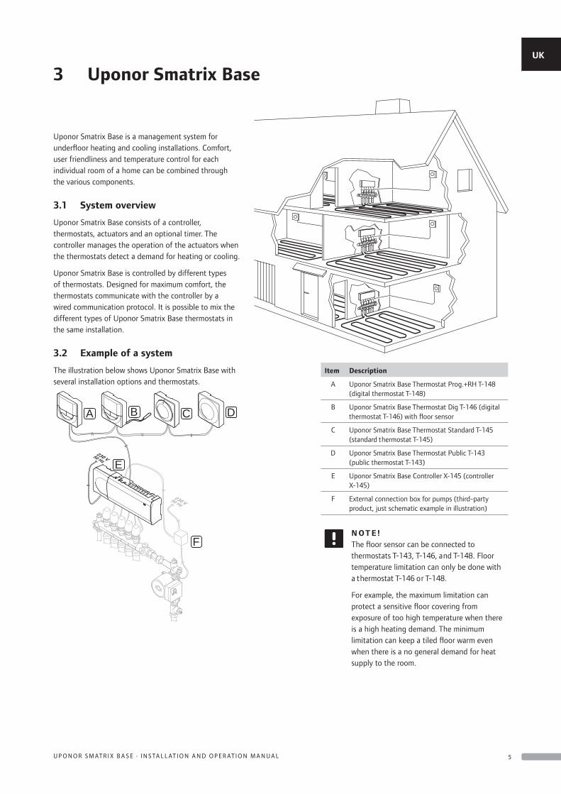
Uponor Smatrix Base is a management system for underfloor heating and cooling installations. Comfort, user friendliness and temperature control for each individual room of a home can be combined through the various components.
3.1 System overview
Uponor Smatrix Base consists of a controller, thermostats, actuators and an optional timer. The controller manages the operation of the actuators when the thermostats detect a demand for heating or cooling.
Uponor Smatrix Base is controlled by different types of thermostats. Designed for maximum comfort, the thermostats communicate with the controller by a wired communication protocol. It is possible to mix the different types of Uponor Smatrix Base thermostats in the same installation.
3.2 Example of a system
The illustration below shows Uponor Smatrix Base with several installation options and thermostats.
F
E
A B C D
Item Description
A Uponor Smatrix Base Thermostat Prog.+RH T-148 (digital thermostat T-148)
B Uponor Smatrix Base Thermostat Dig T-146 (digital thermostat T-146) with floor sensor
C Uponor Smatrix Base Thermostat Standard T-145 (standard thermostat T-145)
D Uponor Smatrix Base Thermostat Public T-143 (public thermostat T-143)
E Uponor Smatrix Base Controller X-145 (controller X-145)
F External connection box for pumps (third-party product, just schematic example in illustration)
N OT E !The floor sensor can be connected to thermostats T-143, T-146, and T-148. Floor temperature limitation can only be done with a thermostat T-146 or T-148.
For example, the maximum limitation can protect a sensitive floor covering from exposure of too high temperature when there is a high heating demand. The minimum limitation can keep a tiled floor warm even when there is a no general demand for heat supply to the room.
UK
CZ
DE
DK
EE
ES
FI
FR
HR
HU
IT
LT
LV
NL
NO
PL
PT
RO
RU
SE
SK
5U P O N O R S M AT R I X B A S E · I N S TA L L AT I O N A N D O P E R AT I O N M A N U A L
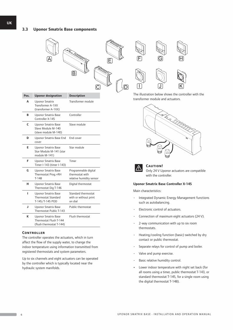
Pos. Uponor designation Description
A Uponor Smatrix Transformer A-1XX (transformer A-1XX)
Transformer module
B Uponor Smatrix Base Controller X-145
Controller
C Uponor Smatrix Base Slave Module M-140 (slave module M-140)
Slave module
D Uponor Smatrix Base End cover
End cover
E Uponor Smatrix Base Star Module M-141 (star module M-141)
Star module
F Uponor Smatrix Base Timer I-143 (timer I-143)
Timer
G Uponor Smatrix Base Thermostat Prog.+RH T-148
Programmable digital thermostat with relative humidity sensor
H Uponor Smatrix Base Thermostat Dig T-146
Digital thermostat
I Uponor Smatrix Base Thermostat Standard T-145/T-145 POD
Standard thermostat with or without print on dial
J Uponor Smatrix Base Thermostat Public T-143
Public thermostat
K Uponor Smatrix Base Thermostat Flush T-144 (flush thermostat T-144)
Flush thermostat
ControllerThe controller operates the actuators, which in turn affect the flow of the supply water, to change the indoor temperature using information transmitted from registered thermostats and system parameters.
Up to six channels and eight actuators can be operated by the controller which is typically located near the hydraulic system manifolds.
The illustration below shows the controller with the transformer module and actuators.
24 V
24 V
24 V
Caution!Only 24 V Uponor actuators are compatible with the controller.
Uponor Smatrix Base Controller X-145
Main characteristics:
• Integrated Dynamic Energy Management functions such as autobalancing.
• Electronic control of actuators.
• Connection of maximum eight actuators (24 V).
• 2-way communication with up to six room thermostats.
• Heating/cooling function (basic) switched by dry contact or public thermostat.
• Separate relays for control of pump and boiler.
• Valve and pump exercise.
• Basic relative humidity control.
• Lower indoor temperature with night set back (for all rooms using a timer, public thermostat T-143, or standard thermostat T-145, for a single room using the digital thermostat T-148).
3.3 Uponor Smatrix Base components
B
C
E
D
F G H
I J K
A
UK
CZ
DE
DK
EE
ES
FI
FR
HR
HU
IT
LT
LV
NL
NO
PL
PT
RO
RU
SE
SK
6 U P O N O R S M AT R I X B A S E · I N S TA L L AT I O N A N D O P E R AT I O N M A N U A L
Options:
• The controller can be expanded with a slave module which adds an extra six channels and six actuator outputs.
• The controller can be expanded with a star module which adds an extra bus connectors to the system. It can be connected to the controller or slave module and is mostly used for a star topology.
• Modular placement (detachable transformer).
• Cabinet or wall mounted (DIN rail or supplied screws).
• Free placement and orientation when installing the controller.
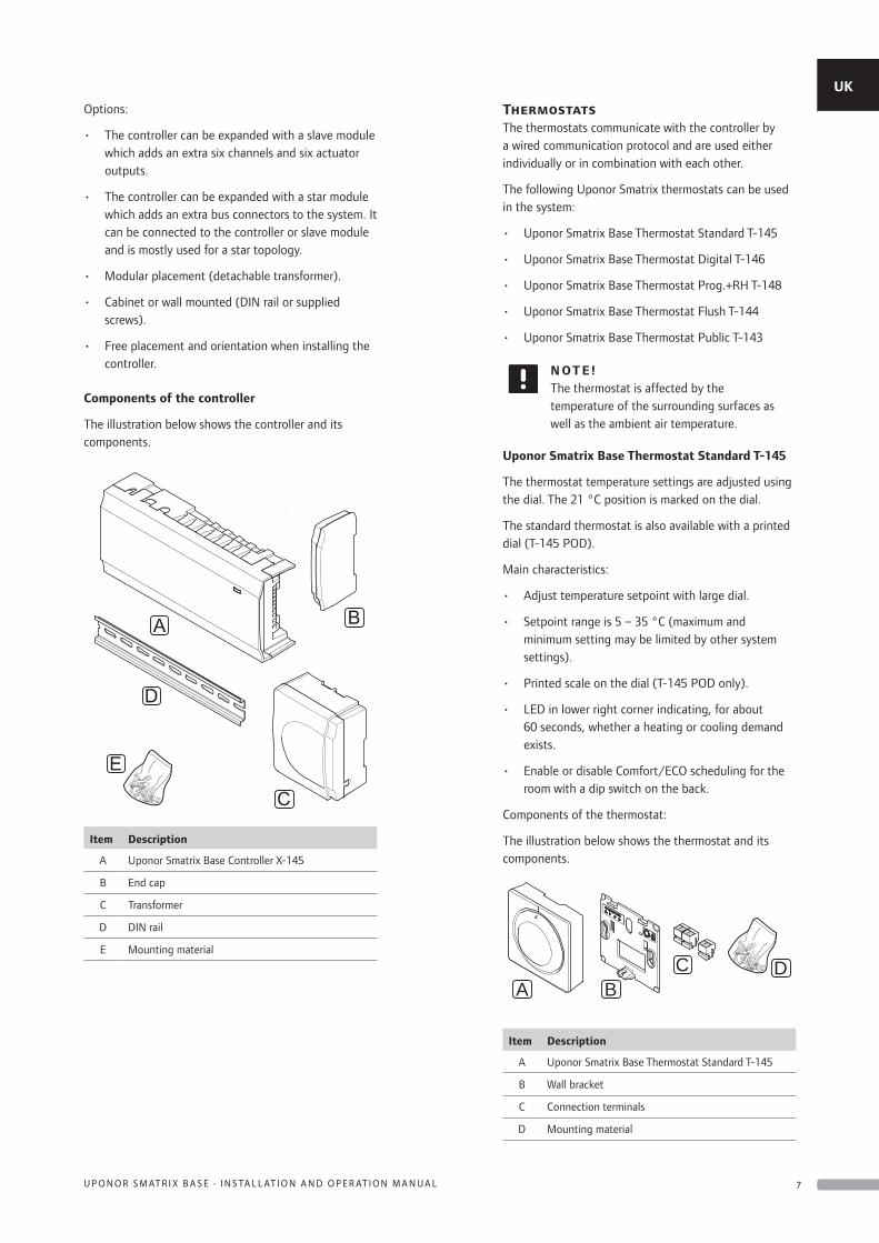
Components of the controller
The illustration below shows the controller and its components.
A
C
B
E
D
Item Description
A Uponor Smatrix Base Controller X-145
B End cap
C Transformer
D DIN rail
E Mounting material
ThermostatsThe thermostats communicate with the controller by a wired communication protocol and are used either individually or in combination with each other.
The following Uponor Smatrix thermostats can be used in the system:
• Uponor Smatrix Base Thermostat Standard T-145
• Uponor Smatrix Base Thermostat Digital T-146
• Uponor Smatrix Base Thermostat Prog.+RH T-148
• Uponor Smatrix Base Thermostat Flush T-144
• Uponor Smatrix Base Thermostat Public T-143
N OT E !The thermostat is affected by the temperature of the surrounding surfaces as well as the ambient air temperature.
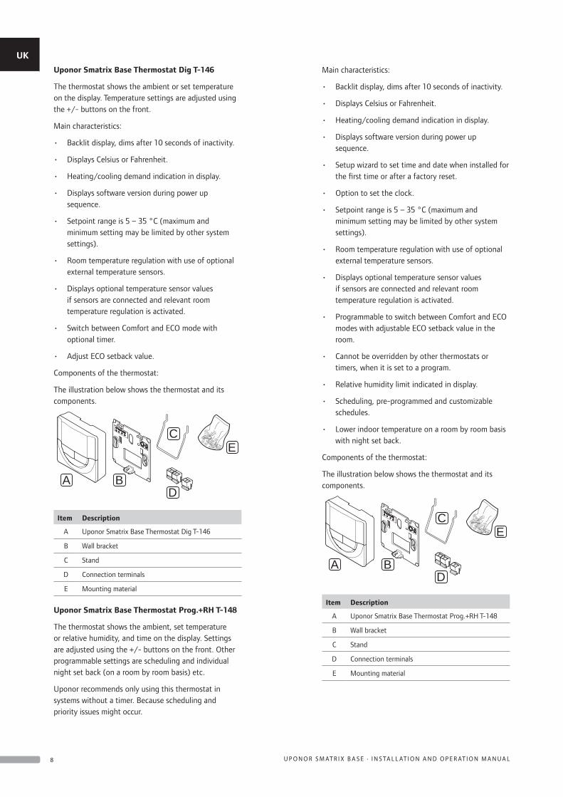
Uponor Smatrix Base Thermostat Standard T-145
The thermostat temperature settings are adjusted using the dial. The 21 °C position is marked on the dial.
The standard thermostat is also available with a printed dial (T-145 POD).
Main characteristics:
• Adjust temperature setpoint with large dial.
• Setpoint range is 5 – 35 °C (maximum and minimum setting may be limited by other system settings).
• Printed scale on the dial (T-145 POD only).
• LED in lower right corner indicating, for about 60 seconds, whether a heating or cooling demand exists.
• Enable or disable Comfort/ECO scheduling for the room with a dip switch on the back.
Components of the thermostat:
The illustration below shows the thermostat and its components.
AD
BC
Item Description
A Uponor Smatrix Base Thermostat Standard T-145
B Wall bracket
C Connection terminals
D Mounting material
UK
CZ
DE
DK
EE
ES
FI
FR
HR
HU
IT
LT
LV
NL
NO
PL
PT
RO
RU
SE
SK
7U P O N O R S M AT R I X B A S E · I N S TA L L AT I O N A N D O P E R AT I O N M A N U A L
Uponor Smatrix Base Thermostat Dig T-146
The thermostat shows the ambient or set temperature on the display. Temperature settings are adjusted using the +/- buttons on the front.
Main characteristics:
• Backlit display, dims after 10 seconds of inactivity.
• Displays Celsius or Fahrenheit.
• Heating/cooling demand indication in display.
• Displays software version during power up sequence.
• Setpoint range is 5 – 35 °C (maximum and minimum setting may be limited by other system settings).
• Room temperature regulation with use of optional external temperature sensors.
• Displays optional temperature sensor values if sensors are connected and relevant room temperature regulation is activated.
• Switch between Comfort and ECO mode with optional timer.
• Adjust ECO setback value.
Components of the thermostat:
The illustration below shows the thermostat and its components.
A
EC
BD
Item Description
A Uponor Smatrix Base Thermostat Dig T-146
B Wall bracket
C Stand
D Connection terminals
E Mounting material
Uponor Smatrix Base Thermostat Prog.+RH T-148
The thermostat shows the ambient, set temperature or relative humidity, and time on the display. Settings are adjusted using the +/- buttons on the front. Other programmable settings are scheduling and individual night set back (on a room by room basis) etc.
Uponor recommends only using this thermostat in systems without a timer. Because scheduling and priority issues might occur.
Main characteristics:
• Backlit display, dims after 10 seconds of inactivity.
• Displays Celsius or Fahrenheit.
• Heating/cooling demand indication in display.
• Displays software version during power up sequence.
• Setup wizard to set time and date when installed for the first time or after a factory reset.
• Option to set the clock.
• Setpoint range is 5 – 35 °C (maximum and minimum setting may be limited by other system settings).
• Room temperature regulation with use of optional external temperature sensors.
• Displays optional temperature sensor values if sensors are connected and relevant room temperature regulation is activated.
• Programmable to switch between Comfort and ECO modes with adjustable ECO setback value in the room.
• Cannot be overridden by other thermostats or timers, when it is set to a program.
• Relative humidity limit indicated in display.
• Scheduling, pre-programmed and customizable schedules.
• Lower indoor temperature on a room by room basis with night set back.
Components of the thermostat:
The illustration below shows the thermostat and its components.
A
EC
BD
Item Description
A Uponor Smatrix Base Thermostat Prog.+RH T-148
B Wall bracket
C Stand
D Connection terminals
E Mounting material
UK
CZ
DE
DK
EE
ES
FI
FR
HR
HU
IT
LT
LV
NL
NO
PL
PT
RO
RU
SE
SK
8 U P O N O R S M AT R I X B A S E · I N S TA L L AT I O N A N D O P E R AT I O N M A N U A L
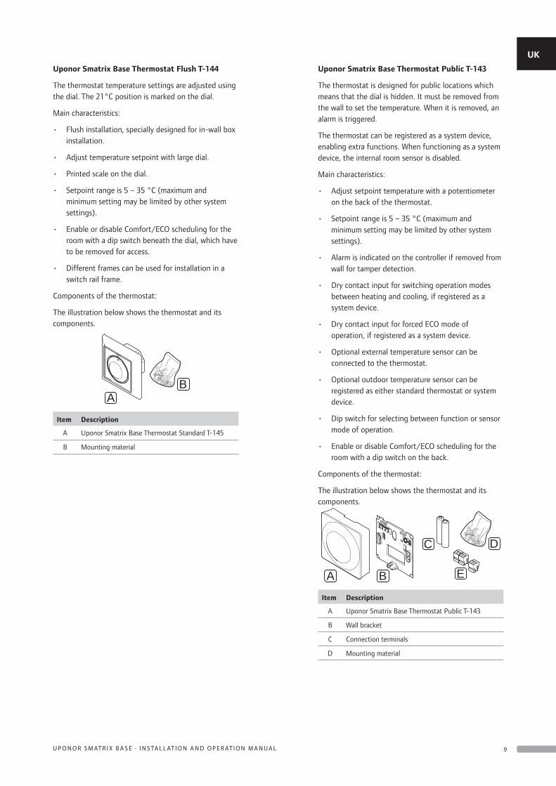
Uponor Smatrix Base Thermostat Flush T-144
The thermostat temperature settings are adjusted using the dial. The 21°C position is marked on the dial.
Main characteristics:
• Flush installation, specially designed for in-wall box installation.
• Adjust temperature setpoint with large dial.
• Printed scale on the dial.
• Setpoint range is 5 – 35 °C (maximum and minimum setting may be limited by other system settings).
• Enable or disable Comfort/ECO scheduling for the room with a dip switch beneath the dial, which have to be removed for access.
• Different frames can be used for installation in a switch rail frame.
Components of the thermostat:
The illustration below shows the thermostat and its components.
AB
Item Description
A Uponor Smatrix Base Thermostat Standard T-145
B Mounting material
Uponor Smatrix Base Thermostat Public T-143
The thermostat is designed for public locations which means that the dial is hidden. It must be removed from the wall to set the temperature. When it is removed, an alarm is triggered.
The thermostat can be registered as a system device, enabling extra functions. When functioning as a system device, the internal room sensor is disabled.
Main characteristics:
• Adjust setpoint temperature with a potentiometer on the back of the thermostat.
• Setpoint range is 5 – 35 °C (maximum and minimum setting may be limited by other system settings).
• Alarm is indicated on the controller if removed from wall for tamper detection.
• Dry contact input for switching operation modes between heating and cooling, if registered as a system device.
• Dry contact input for forced ECO mode of operation, if registered as a system device.
• Optional external temperature sensor can be connected to the thermostat.
• Optional outdoor temperature sensor can be registered as either standard thermostat or system device.
• Dip switch for selecting between function or sensor mode of operation.
• Enable or disable Comfort/ECO scheduling for the room with a dip switch on the back.
Components of the thermostat:
The illustration below shows the thermostat and its components.
A
D
B
C
E
Item Description
A Uponor Smatrix Base Thermostat Public T-143
B Wall bracket
C Connection terminals
D Mounting material
UK
CZ
DE
DK
EE
ES
FI
FR
HR
HU
IT
LT
LV
NL
NO
PL
PT
RO
RU
SE
SK
9U P O N O R S M AT R I X B A S E · I N S TA L L AT I O N A N D O P E R AT I O N M A N U A L
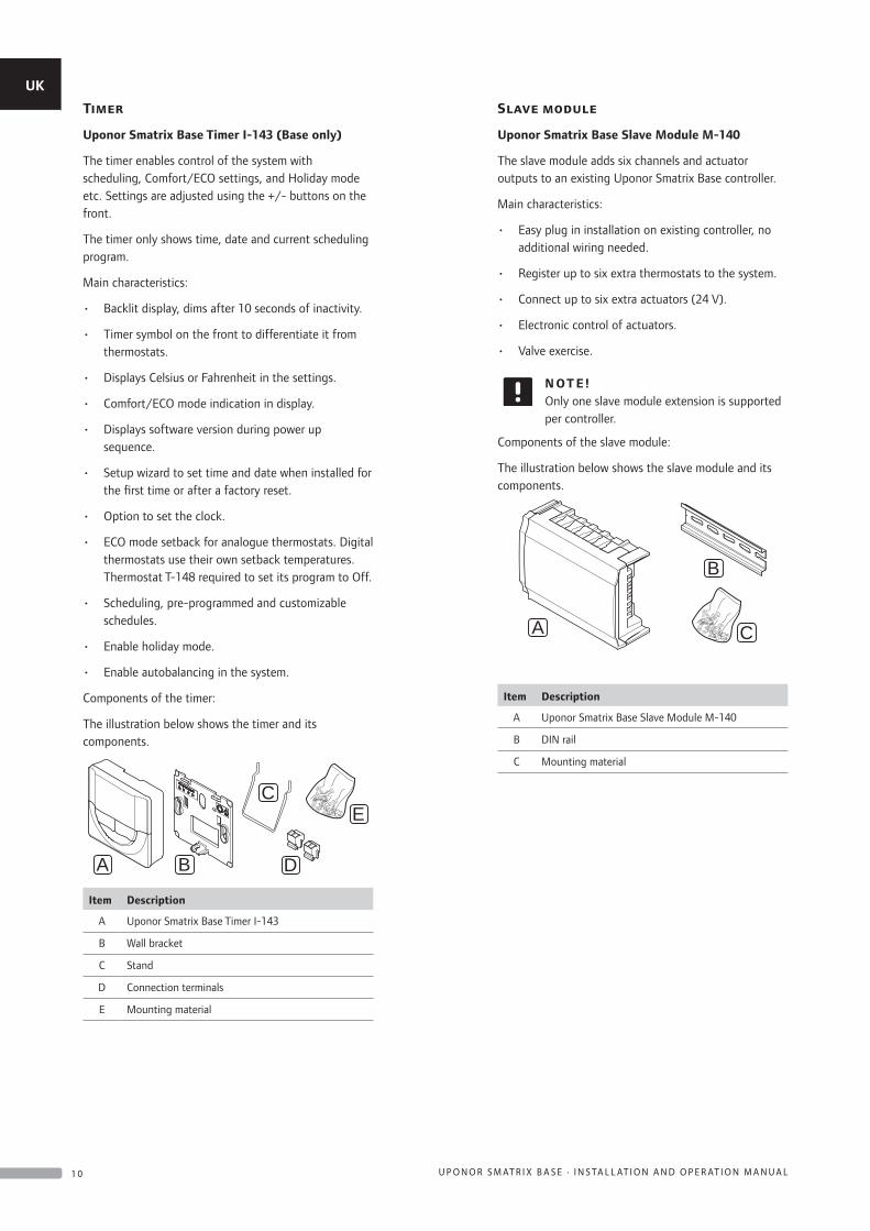
Timer
Uponor Smatrix Base Timer I-143 (Base only)
The timer enables control of the system with scheduling, Comfort/ECO settings, and Holiday mode etc. Settings are adjusted using the +/- buttons on the front.
The timer only shows time, date and current scheduling program.
Main characteristics:
• Backlit display, dims after 10 seconds of inactivity.
• Timer symbol on the front to differentiate it from thermostats.
• Displays Celsius or Fahrenheit in the settings.
• Comfort/ECO mode indication in display.
• Displays software version during power up sequence.
• Setup wizard to set time and date when installed for the first time or after a factory reset.
• Option to set the clock.
• ECO mode setback for analogue thermostats. Digital thermostats use their own setback temperatures. Thermostat T-148 required to set its program to Off.
• Scheduling, pre-programmed and customizable schedules.
• Enable holiday mode.
• Enable autobalancing in the system.
Components of the timer:
The illustration below shows the timer and its components.
A
EC
B D
Item Description
A Uponor Smatrix Base Timer I-143
B Wall bracket
C Stand
D Connection terminals
E Mounting material
Slave module
Uponor Smatrix Base Slave Module M-140
The slave module adds six channels and actuator outputs to an existing Uponor Smatrix Base controller.
Main characteristics:
• Easy plug in installation on existing controller, no additional wiring needed.
• Register up to six extra thermostats to the system.
• Connect up to six extra actuators (24 V).
• Electronic control of actuators.
• Valve exercise.
N OT E !Only one slave module extension is supported per controller.
Components of the slave module:
The illustration below shows the slave module and its components.
A
B
C
Item Description
A Uponor Smatrix Base Slave Module M-140
B DIN rail
C Mounting material
UK
CZ
DE
DK
EE
ES
FI
FR
HR
HU
IT
LT
LV
NL
NO
PL
PT
RO
RU
SE
SK
1 0 U P O N O R S M AT R I X B A S E · I N S TA L L AT I O N A N D O P E R AT I O N M A N U A L
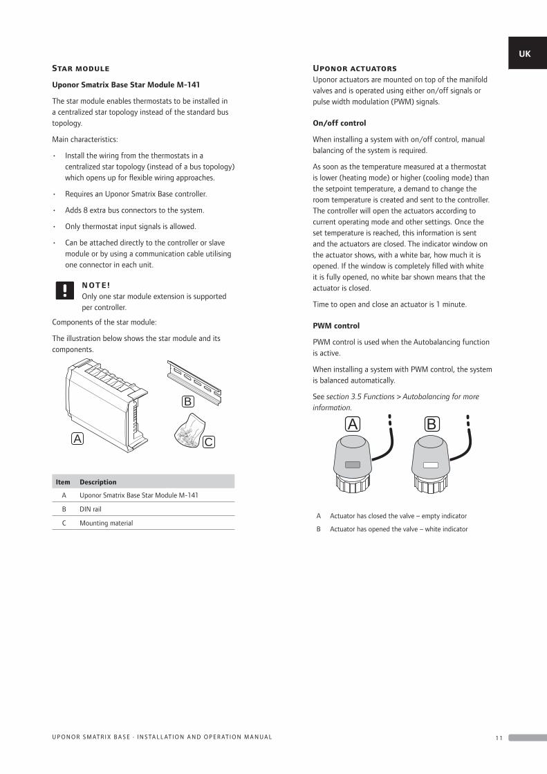
Star module
Uponor Smatrix Base Star Module M-141
The star module enables thermostats to be installed in a centralized star topology instead of the standard bus topology.
Main characteristics:
• Install the wiring from the thermostats in a centralized star topology (instead of a bus topology) which opens up for flexible wiring approaches.
• Requires an Uponor Smatrix Base controller.
• Adds 8 extra bus connectors to the system.
• Only thermostat input signals is allowed.
• Can be attached directly to the controller or slave module or by using a communication cable utilising one connector in each unit.
N OT E !Only one star module extension is supported per controller.
Components of the star module:
The illustration below shows the star module and its components.
A
B
C
Item Description
A Uponor Smatrix Base Star Module M-141
B DIN rail
C Mounting material
Uponor actuatorsUponor actuators are mounted on top of the manifold valves and is operated using either on/off signals or pulse width modulation (PWM) signals.
On/off control
When installing a system with on/off control, manual balancing of the system is required.
As soon as the temperature measured at a thermostat is lower (heating mode) or higher (cooling mode) than the setpoint temperature, a demand to change the room temperature is created and sent to the controller. The controller will open the actuators according to current operating mode and other settings. Once the set temperature is reached, this information is sent and the actuators are closed. The indicator window on the actuator shows, with a white bar, how much it is opened. If the window is completely filled with white it is fully opened, no white bar shown means that the actuator is closed.
Time to open and close an actuator is 1 minute.
PWM control
PWM control is used when the Autobalancing function is active.
When installing a system with PWM control, the system is balanced automatically.
See section 3.5 Functions > Autobalancing for more information.
A B
A Actuator has closed the valve – empty indicator
B Actuator has opened the valve – white indicator
UK
CZ
DE
DK
EE
ES
FI
FR
HR
HU
IT
LT
LV
NL
NO
PL
PT
RO
RU
SE
SK
1 1U P O N O R S M AT R I X B A S E · I N S TA L L AT I O N A N D O P E R AT I O N M A N U A L
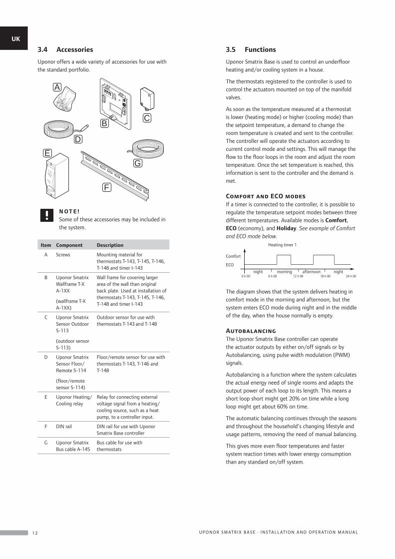
3.4 Accessories
Uponor offers a wide variety of accessories for use with the standard portfolio.
F
A
ED
B C
G
N OT E !Some of these accessories may be included in the system.
Item Component Description
A Screws Mounting material for thermostats T-143, T-145, T-146, T-148 and timer I-143
B Uponor Smatrix Wallframe T-X A-1XX
(wallframe T-X A-1XX)
Wall frame for covering larger area of the wall than original back plate. Used at installation of thermostats T-143, T-145, T-146, T-148 and timer I-143
C Uponor Smatrix Sensor Outdoor S-113
(outdoor sensor S-113)
Outdoor sensor for use with thermostats T-143 and T-148
D Uponor Smatrix Sensor Floor/Remote S-114
(floor/remote sensor S-114)
Floor/remote sensor for use with thermostats T-143, T-146 and T-148
E Uponor Heating/Cooling relay
Relay for connecting external voltage signal from a heating/cooling source, such as a heat pump, to a controller input.
F DIN rail DIN rail for use with Uponor Smatrix Base controller
G Uponor Smatrix Bus cable A-145
Bus cable for use with thermostats
3.5 Functions
Uponor Smatrix Base is used to control an underfloor heating and/or cooling system in a house.
The thermostats registered to the controller is used to control the actuators mounted on top of the manifold valves.
As soon as the temperature measured at a thermostat is lower (heating mode) or higher (cooling mode) than the setpoint temperature, a demand to change the room temperature is created and sent to the controller. The controller will operate the actuators according to current control mode and settings. This will manage the flow to the floor loops in the room and adjust the room temperature. Once the set temperature is reached, this information is sent to the controller and the demand is met.
Comfort and ECO modesIf a timer is connected to the controller, it is possible to regulate the temperature setpoint modes between three different temperatures. Available modes is Comfort, ECO (economy), and Holiday. See example of Comfort and ECO mode below.
0 h 00 24 h 0018 h 0012 h 006 h 00
Comfort
ECO
Heating timer 1
night morning afternoon night
The diagram shows that the system delivers heating in comfort mode in the morning and afternoon, but the system enters ECO mode during night and in the middle of the day, when the house normally is empty.
AutobalancingThe Uponor Smatrix Base controller can operate the actuator outputs by either on/off signals or by Autobalancing, using pulse width modulation (PWM) signals.
Autobalancing is a function where the system calculates the actual energy need of single rooms and adapts the output power of each loop to its length. This means a short loop short might get 20% on time while a long loop might get about 60% on time.
The automatic balancing continues through the seasons and throughout the household’s changing lifestyle and usage patterns, removing the need of manual balancing.
This gives more even floor temperatures and faster system reaction times with lower energy consumption than any standard on/off system.
UK
CZ
DE
DK
EE
ES
FI
FR
HR
HU
IT
LT
LV
NL
NO
PL
PT
RO
RU
SE
SK
1 2 U P O N O R S M AT R I X B A S E · I N S TA L L AT I O N A N D O P E R AT I O N M A N U A L
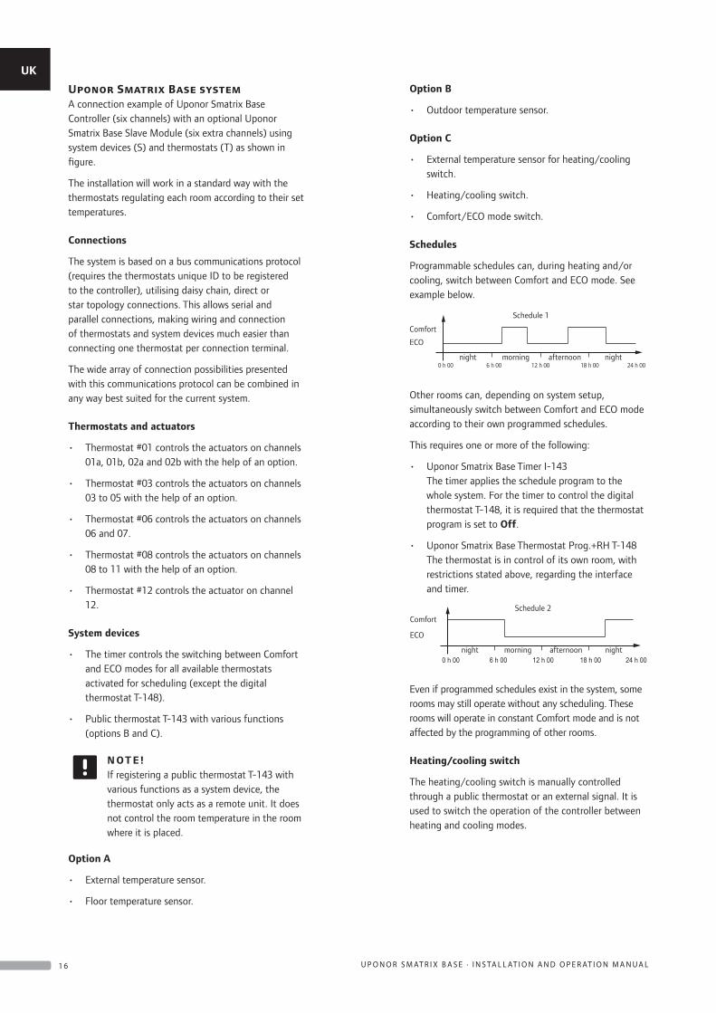
Low hysteresis temperatureUponor uses a low hysteresis temperature for best performance of the system. It is used for high control accuracy by deciding when to start and stop heating and cooling, based on information from sensors and setpoint values.
Heating/cooling offsetUponor uses an offset temperature to adjust the setpoints when switching between heating and cooling. This improves the performance of the system and reduces the need of manual setpoint adjustments when switching between heating and cooling.
The default value is set to 2 °C and is used to increase the setpoints when switching to cooling. When switching back to heating, the value is used to reduce the setpoint.
Relative humidity functionTo avoid condensation when having a cooling system, it is recommended measuring the relative humidity (RH) in the rooms. The relative humidity is measured with one or more thermostats (with RH sensor).
Cooling is shut off for the whole system if the RH reaches a “worst case level” of 80% in one of the thermostats (if more than one).
Cooling will start again when the relative humidity falls below 76%.
Actuator managementActuator management prevents too many actuators to be open at the same time in order to reduce the peak power need. Peak current can be reduced by delaying the opening of some actuators, as they use most current while being opened.
Up to eight actuators in up to six rooms can be opened at the same time. Additional actuators are queued and opened in order.
Pump managementEach controller in a system has a pump relay, to which one pump can be connected. If there is some sort of demand in a room, the pump is started.
Heating fall backIf the connection to a thermostat is lost, the corresponding loop cannot be regulated using the air temperature. The controller then activates a fall back function for the affected loop and the actuators are operated with a set interval.
The function is activated until the thermostat is reconnected.
System clockTo facilitate scheduling and different timer settings, the controller receives the correct time and date from one of the input devices (timer, programmable thermostat etc). The clock can be set to automatically switch between summer and winter time.
UK
CZ
DE
DK
EE
ES
FI
FR
HR
HU
IT
LT
LV
NL
NO
PL
PT
RO
RU
SE
SK
1 3U P O N O R S M AT R I X B A S E · I N S TA L L AT I O N A N D O P E R AT I O N M A N U A L
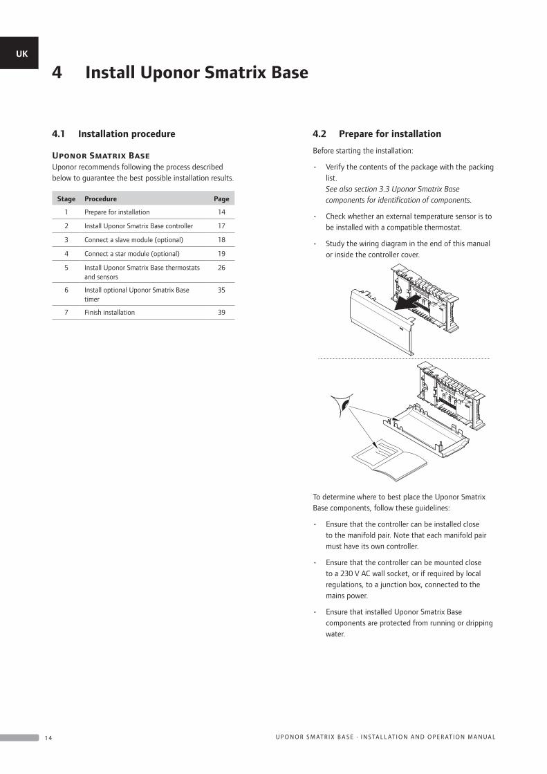
4 Install Uponor Smatrix Base
4.1 Installation procedure
Uponor Smatrix BaseUponor recommends following the process described below to guarantee the best possible installation results.
Stage Procedure Page
1 Prepare for installation 14
2 Install Uponor Smatrix Base controller 17
3 Connect a slave module (optional) 18
4 Connect a star module (optional) 19
5 Install Uponor Smatrix Base thermostats and sensors
26
6 Install optional Uponor Smatrix Base timer
35
7 Finish installation 39
4.2 Prepare for installation
Before starting the installation:
• Verify the contents of the package with the packing list. See also section 3.3 Uponor Smatrix Base components for identification of components.
• Check whether an external temperature sensor is to be installed with a compatible thermostat.
• Study the wiring diagram in the end of this manual or inside the controller cover.
To determine where to best place the Uponor Smatrix Base components, follow these guidelines:
• Ensure that the controller can be installed close to the manifold pair. Note that each manifold pair must have its own controller.
• Ensure that the controller can be mounted close to a 230 V AC wall socket, or if required by local regulations, to a junction box, connected to the mains power.
• Ensure that installed Uponor Smatrix Base components are protected from running or dripping water.
UK
CZ
DE
DK
EE
ES
FI
FR
HR
HU
IT
LT
LV
NL
NO
PL
PT
RO
RU
SE
SK
1 4 U P O N O R S M AT R I X B A S E · I N S TA L L AT I O N A N D O P E R AT I O N M A N U A L
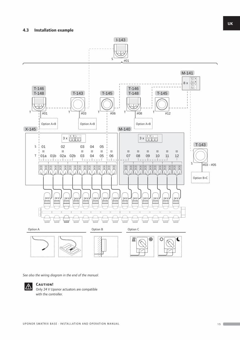
4.3 Installation example
See also the wiring diagram in the end of the manual.
Caution!Only 24 V Uponor actuators are compatible with the controller.
24 V 24 V 24 V 24 V 24 V 24 V 24 V 24 V 24 V 24 V 24 V 24 V 24 V 24 V
03
#01
#01
#08 #12#03
02a 02b01b01a 09 10 11 12080704 05
030201 04 05
06
M-140
M-141
8 x
3 x3 x
I-143
T-143 T-145
X-145
T-146T-148
T-146T-148
OptionA+B
OptionA+B
Option A Option COption B
T
S
TT T T#06
T-145
T
S
OptionA+B+C
#03 - #05
T-143
S
OptionB+C
AB+-
A B + - A B + -
Option A+B
Option A Option B Option C
Option A+BOption A+B
Option B+C
UK
CZ
DE
DK
EE
ES
FI
FR
HR
HU
IT
LT
LV
NL
NO
PL
PT
RO
RU
SE
SK
1 5U P O N O R S M AT R I X B A S E · I N S TA L L AT I O N A N D O P E R AT I O N M A N U A L
Uponor Smatrix Base systemA connection example of Uponor Smatrix Base Controller (six channels) with an optional Uponor Smatrix Base Slave Module (six extra channels) using system devices (S) and thermostats (T) as shown in figure.
The installation will work in a standard way with the thermostats regulating each room according to their set temperatures.
Connections
The system is based on a bus communications protocol (requires the thermostats unique ID to be registered to the controller), utilising daisy chain, direct or star topology connections. This allows serial and parallel connections, making wiring and connection of thermostats and system devices much easier than connecting one thermostat per connection terminal.
The wide array of connection possibilities presented with this communications protocol can be combined in any way best suited for the current system.
Thermostats and actuators
• Thermostat #01 controls the actuators on channels 01a, 01b, 02a and 02b with the help of an option.
• Thermostat #03 controls the actuators on channels 03 to 05 with the help of an option.
• Thermostat #06 controls the actuators on channels 06 and 07.
• Thermostat #08 controls the actuators on channels 08 to 11 with the help of an option.
• Thermostat #12 controls the actuator on channel 12.
System devices
• The timer controls the switching between Comfort and ECO modes for all available thermostats activated for scheduling (except the digital thermostat T-148).
• Public thermostat T-143 with various functions (options B and C).
N OT E !If registering a public thermostat T-143 with various functions as a system device, the thermostat only acts as a remote unit. It does not control the room temperature in the room where it is placed.
Option A
• External temperature sensor.
• Floor temperature sensor.
Option B
• Outdoor temperature sensor.
Option C
• External temperature sensor for heating/cooling switch.
• Heating/cooling switch.
• Comfort/ECO mode switch.
Schedules
Programmable schedules can, during heating and/or cooling, switch between Comfort and ECO mode. See example below.
0 h 00 24 h 0018 h 0012 h 006 h 00
Comfort
ECO
Schedule 1
night morning afternoon night
Other rooms can, depending on system setup, simultaneously switch between Comfort and ECO mode according to their own programmed schedules.
This requires one or more of the following:
• Uponor Smatrix Base Timer I-143 The timer applies the schedule program to the whole system. For the timer to control the digital thermostat T-148, it is required that the thermostat program is set to Off.
• Uponor Smatrix Base Thermostat Prog.+RH T-148 The thermostat is in control of its own room, with restrictions stated above, regarding the interface and timer.
0 h 00 24 h 0018 h 0012 h 006 h 00
Comfort
ECO
Schedule 2
night morning afternoon night
Even if programmed schedules exist in the system, some rooms may still operate without any scheduling. These rooms will operate in constant Comfort mode and is not affected by the programming of other rooms.
Heating/cooling switch
The heating/cooling switch is manually controlled through a public thermostat or an external signal. It is used to switch the operation of the controller between heating and cooling modes.
UK
CZ
DE
DK
EE
ES
FI
FR
HR
HU
IT
LT
LV
NL
NO
PL
PT
RO
RU
SE
SK
1 6 U P O N O R S M AT R I X B A S E · I N S TA L L AT I O N A N D O P E R AT I O N M A N U A L
5 Install Uponor Smatrix Base controller
5.1 Placement of controller
Refer to the installation preparation guidelines (see section 4.2 Prepare for installation), and use the following guidelines when positioning the controller:
• Position the controller just above the manifold. Check the position of the 230 V AC power outlet.
• Check that the cover of the controller can be easily removed.
• Check that connectors and switches are easily accessible.
Modular placementThe controller is designed with the option of modular placement in mind. This means that all major parts are detachable and can be placed separately (some extra wiring may be required depending on placement).
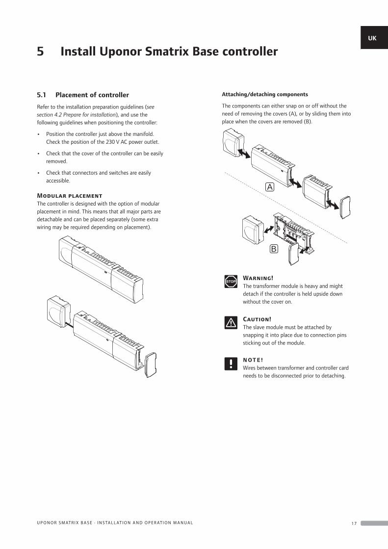
Attaching/detaching components
The components can either snap on or off without the need of removing the covers (A), or by sliding them into place when the covers are removed (B).
B
A
Warning!The transformer module is heavy and might detach if the controller is held upside down without the cover on.
Caution!The slave module must be attached by snapping it into place due to connection pins sticking out of the module.
N OT E !Wires between transformer and controller card needs to be disconnected prior to detaching.
UK
CZ
DE
DK
EE
ES
FI
FR
HR
HU
IT
LT
LV
NL
NO
PL
PT
RO
RU
SE
SK
1 7U P O N O R S M AT R I X B A S E · I N S TA L L AT I O N A N D O P E R AT I O N M A N U A L
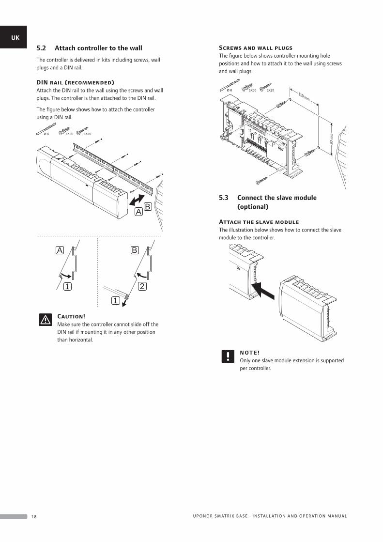
5.2 Attach controller to the wall
The controller is delivered in kits including screws, wall plugs and a DIN rail.
DIN rail (recommended)Attach the DIN rail to the wall using the screws and wall plugs. The controller is then attached to the DIN rail.
The figure below shows how to attach the controller using a DIN rail.
A B
1
1 2
A B
Caution!Make sure the controller cannot slide off the DIN rail if mounting it in any other position than horizontal.
Screws and wall plugsThe figure below shows controller mounting hole positions and how to attach it to the wall using screws and wall plugs.
110 mm
80 m
m
5.3 Connect the slave module (optional)
Attach the slave moduleThe illustration below shows how to connect the slave module to the controller.
N OT E !Only one slave module extension is supported per controller.
UK
CZ
DE
DK
EE
ES
FI
FR
HR
HU
IT
LT
LV
NL
NO
PL
PT
RO
RU
SE
SK
1 8 U P O N O R S M AT R I X B A S E · I N S TA L L AT I O N A N D O P E R AT I O N M A N U A L
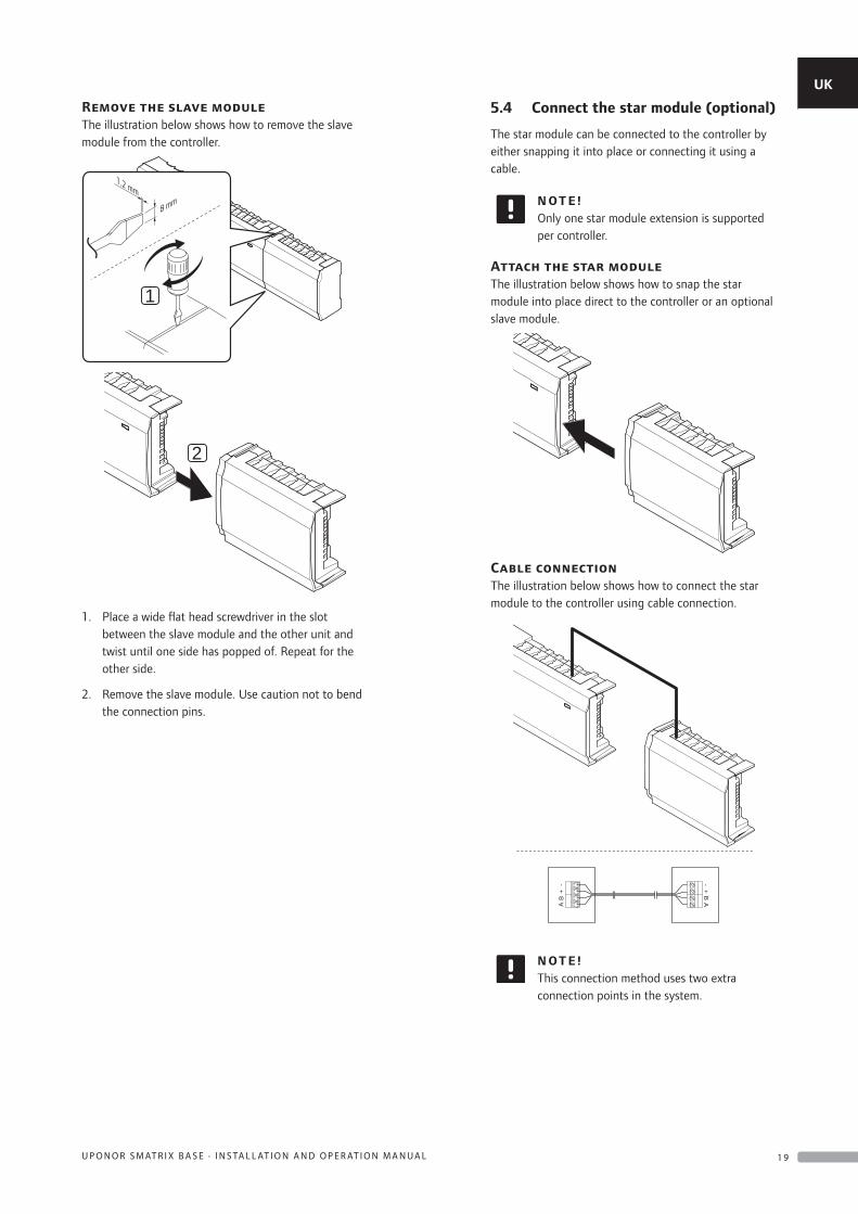
Remove the slave moduleThe illustration below shows how to remove the slave module from the controller.
1
1.2 mm
8 mm
2
1. Place a wide flat head screwdriver in the slot between the slave module and the other unit and twist until one side has popped of. Repeat for the other side.
2. Remove the slave module. Use caution not to bend the connection pins.
5.4 Connect the star module (optional)
The star module can be connected to the controller by either snapping it into place or connecting it using a cable.
N OT E !Only one star module extension is supported per controller.
Attach the star moduleThe illustration below shows how to snap the star module into place direct to the controller or an optional slave module.
Cable connectionThe illustration below shows how to connect the star module to the controller using cable connection.
AB
+- -
+B
A
N OT E !This connection method uses two extra connection points in the system.
UK
CZ
DE
DK
EE
ES
FI
FR
HR
HU
IT
LT
LV
NL
NO
PL
PT
RO
RU
SE
SK
1 9U P O N O R S M AT R I X B A S E · I N S TA L L AT I O N A N D O P E R AT I O N M A N U A L
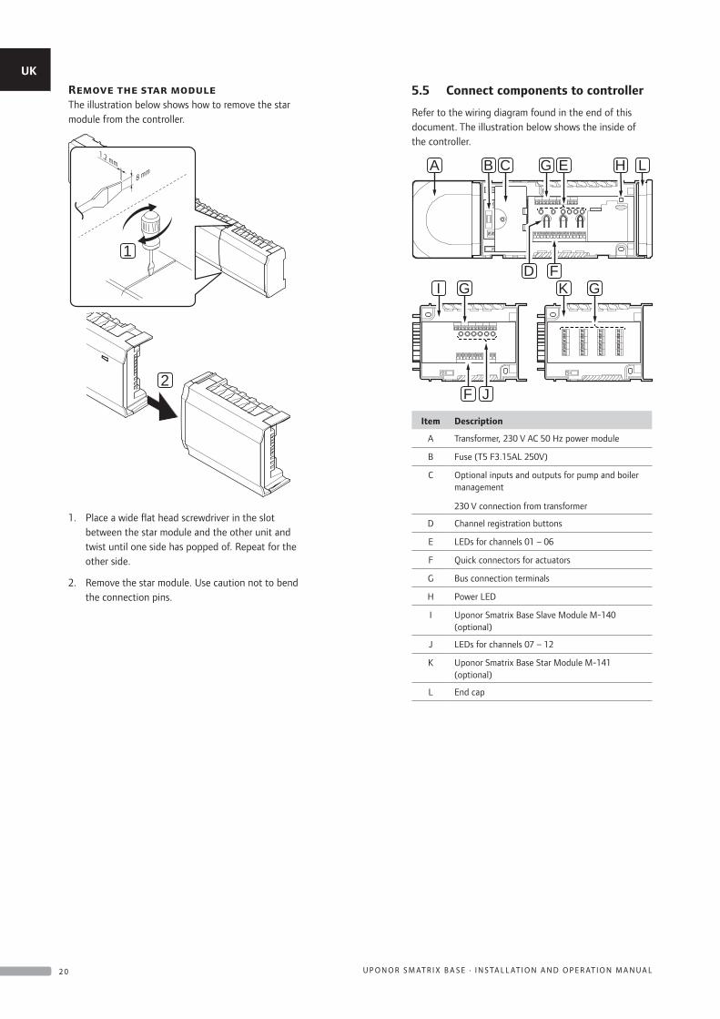
Remove the star moduleThe illustration below shows how to remove the star module from the controller.
1
1.2 mm
8 mm
2
1. Place a wide flat head screwdriver in the slot between the star module and the other unit and twist until one side has popped of. Repeat for the other side.
2. Remove the star module. Use caution not to bend the connection pins.
5.5 Connect components to controller
Refer to the wiring diagram found in the end of this document. The illustration below shows the inside of the controller.
E H
FD
C GB LA
I
F J
G K G
Item Description
A Transformer, 230 V AC 50 Hz power module
B Fuse (T5 F3.15AL 250V)
C Optional inputs and outputs for pump and boiler management
230 V connection from transformer
D Channel registration buttons
E LEDs for channels 01 – 06
F Quick connectors for actuators
G Bus connection terminals
H Power LED
I Uponor Smatrix Base Slave Module M-140 (optional)
J LEDs for channels 07 – 12
K Uponor Smatrix Base Star Module M-141 (optional)
L End cap
UK
CZ
DE
DK
EE
ES
FI
FR
HR
HU
IT
LT
LV
NL
NO
PL
PT
RO
RU
SE
SK
2 0 U P O N O R S M AT R I X B A S E · I N S TA L L AT I O N A N D O P E R AT I O N M A N U A L
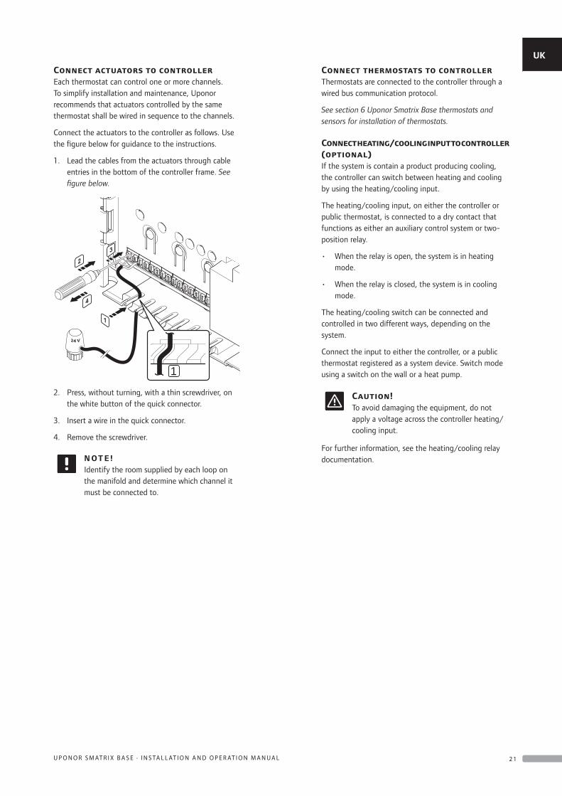
Connect actuators to controllerEach thermostat can control one or more channels. To simplify installation and maintenance, Uponor recommends that actuators controlled by the same thermostat shall be wired in sequence to the channels.
Connect the actuators to the controller as follows. Use the figure below for guidance to the instructions.
1. Lead the cables from the actuators through cable entries in the bottom of the controller frame. See figure below.
1
2. Press, without turning, with a thin screwdriver, on the white button of the quick connector.
3. Insert a wire in the quick connector.
4. Remove the screwdriver.
N OT E !Identify the room supplied by each loop on the manifold and determine which channel it must be connected to.
Connect thermostats to controllerThermostats are connected to the controller through a wired bus communication protocol.
See section 6 Uponor Smatrix Base thermostats and sensors for installation of thermostats.
Connect heating/cooling input to controller (optional)If the system is contain a product producing cooling, the controller can switch between heating and cooling by using the heating/cooling input.
The heating/cooling input, on either the controller or public thermostat, is connected to a dry contact that functions as either an auxiliary control system or two-position relay.
• When the relay is open, the system is in heating mode.
• When the relay is closed, the system is in cooling mode.
The heating/cooling switch can be connected and controlled in two different ways, depending on the system.
Connect the input to either the controller, or a public thermostat registered as a system device. Switch mode using a switch on the wall or a heat pump.
Caution!To avoid damaging the equipment, do not apply a voltage across the controller heating/cooling input.
For further information, see the heating/cooling relay documentation.
UK
CZ
DE
DK
EE
ES
FI
FR
HR
HU
IT
LT
LV
NL
NO
PL
PT
RO
RU
SE
SK
2 1U P O N O R S M AT R I X B A S E · I N S TA L L AT I O N A N D O P E R AT I O N M A N U A L
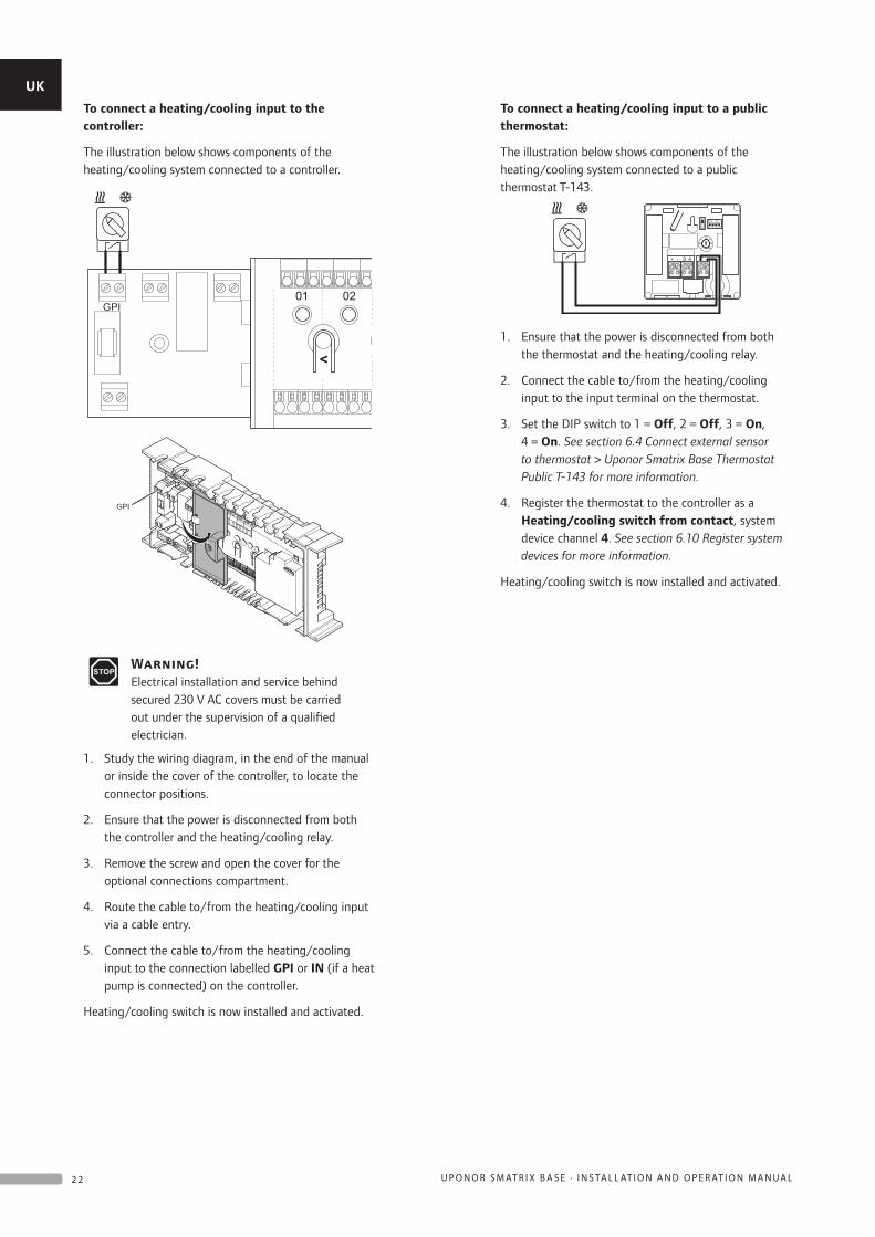
To connect a heating/cooling input to the controller:
The illustration below shows components of the heating/cooling system connected to a controller.
GPI
GPI
Warning!Electrical installation and service behind secured 230 V AC covers must be carried out under the supervision of a qualified electrician.
1. Study the wiring diagram, in the end of the manual or inside the cover of the controller, to locate the connector positions.
2. Ensure that the power is disconnected from both the controller and the heating/cooling relay.
3. Remove the screw and open the cover for the optional connections compartment.
4. Route the cable to/from the heating/cooling input via a cable entry.
5. Connect the cable to/from the heating/cooling input to the connection labelled GPI or IN (if a heat pump is connected) on the controller.
Heating/cooling switch is now installed and activated.
To connect a heating/cooling input to a public thermostat:
The illustration below shows components of the heating/cooling system connected to a public thermostat T-143.
20
5 35
1 2 3 4
ON DIP
+ - B A
1. Ensure that the power is disconnected from both the thermostat and the heating/cooling relay.
2. Connect the cable to/from the heating/cooling input to the input terminal on the thermostat.
3. Set the DIP switch to 1 = Off, 2 = Off, 3 = On, 4 = On. See section 6.4 Connect external sensor to thermostat > Uponor Smatrix Base Thermostat Public T-143 for more information.
4. Register the thermostat to the controller as a Heating/cooling switch from contact, system device channel 4. See section 6.10 Register system devices for more information.
Heating/cooling switch is now installed and activated.
UK
CZ
DE
DK
EE
ES
FI
FR
HR
HU
IT
LT
LV
NL
NO
PL
PT
RO
RU
SE
SK
2 2 U P O N O R S M AT R I X B A S E · I N S TA L L AT I O N A N D O P E R AT I O N M A N U A L
Connect pump management (optional)The controller can operate a circulation pump, which stops when there is no demand for heating or cooling.
N OT E !See the documentation from the circulation pump supplier as well as relevant Uponor wiring diagrams before connecting the pump.
• The controller cannot supply power for the pump.
• The controller uses a dry contact connection on the terminal block to control the circulation pump.
• The electrical circuits of the pump must be protected by a circuit breaker with a maximum rating of 8 A.
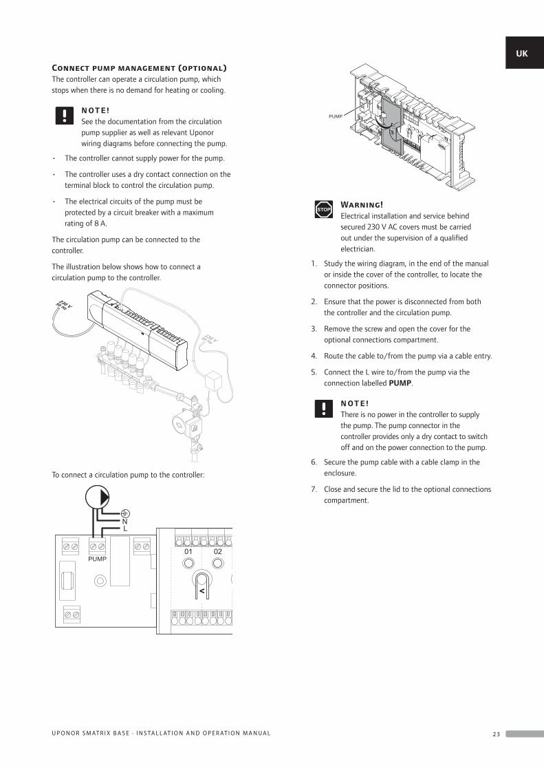
The circulation pump can be connected to the controller.
The illustration below shows how to connect a circulation pump to the controller.
To connect a circulation pump to the controller:
PUMP
PUMP
Warning!Electrical installation and service behind secured 230 V AC covers must be carried out under the supervision of a qualified electrician.
1. Study the wiring diagram, in the end of the manual or inside the cover of the controller, to locate the connector positions.
2. Ensure that the power is disconnected from both the controller and the circulation pump.
3. Remove the screw and open the cover for the optional connections compartment.
4. Route the cable to/from the pump via a cable entry.
5. Connect the L wire to/from the pump via the connection labelled PUMP.
N OT E !There is no power in the controller to supply the pump. The pump connector in the controller provides only a dry contact to switch off and on the power connection to the pump.
6. Secure the pump cable with a cable clamp in the enclosure.
7. Close and secure the lid to the optional connections compartment.
UK
CZ
DE
DK
EE
ES
FI
FR
HR
HU
IT
LT
LV
NL
NO
PL
PT
RO
RU
SE
SK
2 3U P O N O R S M AT R I X B A S E · I N S TA L L AT I O N A N D O P E R AT I O N M A N U A L
Connect boiler (optional)The controller includes a boiler relay, it can be used to send a signal to either fire the heat source or to power open a 2-port motorised zone valve positioned on the flow to the underfloor heating manifold. If the relay is used to power open a zone valve then, the volt free auxiliary contacts on the zone valve should be used to fire the heat source.
Alternatively, the boiler relay can be used to send a demand signal to an electrically operated water temperature controller. The additional contacts on the water temperature controller should then be used to fire the heat source.
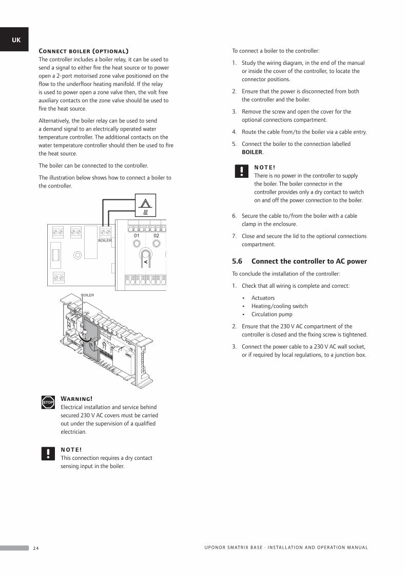
The boiler can be connected to the controller.
The illustration below shows how to connect a boiler to the controller.
BOILER
BOILER
Warning!Electrical installation and service behind secured 230 V AC covers must be carried out under the supervision of a qualified electrician.
N OT E !This connection requires a dry contact sensing input in the boiler.
To connect a boiler to the controller:
1. Study the wiring diagram, in the end of the manual or inside the cover of the controller, to locate the connector positions.
2. Ensure that the power is disconnected from both the controller and the boiler.
3. Remove the screw and open the cover for the optional connections compartment.
4. Route the cable from/to the boiler via a cable entry.
5. Connect the boiler to the connection labelled BOILER.
N OT E !There is no power in the controller to supply the boiler. The boiler connector in the controller provides only a dry contact to switch on and off the power connection to the boiler.
6. Secure the cable to/from the boiler with a cable clamp in the enclosure.
7. Close and secure the lid to the optional connections compartment.
5.6 Connect the controller to AC power
To conclude the installation of the controller:
1. Check that all wiring is complete and correct:
• Actuators • Heating/cooling switch • Circulation pump
2. Ensure that the 230 V AC compartment of the controller is closed and the fixing screw is tightened.
3. Connect the power cable to a 230 V AC wall socket, or if required by local regulations, to a junction box.
UK
CZ
DE
DK
EE
ES
FI
FR
HR
HU
IT
LT
LV
NL
NO
PL
PT
RO
RU
SE
SK
2 4 U P O N O R S M AT R I X B A S E · I N S TA L L AT I O N A N D O P E R AT I O N M A N U A L
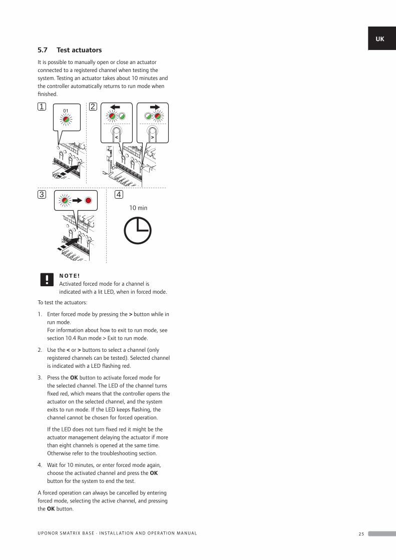
5.7 Test actuators
It is possible to manually open or close an actuator connected to a registered channel when testing the system. Testing an actuator takes about 10 minutes and the controller automatically returns to run mode when finished.
21
10 min
3 410 min
N OT E !Activated forced mode for a channel is indicated with a lit LED, when in forced mode.
To test the actuators:
1. Enter forced mode by pressing the > button while in run mode. For information about how to exit to run mode, see section 10.4 Run mode > Exit to run mode.
2. Use the < or > buttons to select a channel (only registered channels can be tested). Selected channel is indicated with a LED flashing red.
3. Press the OK button to activate forced mode for the selected channel. The LED of the channel turns fixed red, which means that the controller opens the actuator on the selected channel, and the system exits to run mode. If the LED keeps flashing, the channel cannot be chosen for forced operation.
If the LED does not turn fixed red it might be the actuator management delaying the actuator if more than eight channels is opened at the same time. Otherwise refer to the troubleshooting section.
4. Wait for 10 minutes, or enter forced mode again, choose the activated channel and press the OK button for the system to end the test.
A forced operation can always be cancelled by entering forced mode, selecting the active channel, and pressing the OK button.
UK
CZ
DE
DK
EE
ES
FI
FR
HR
HU
IT
LT
LV
NL
NO
PL
PT
RO
RU
SE
SK
2 5U P O N O R S M AT R I X B A S E · I N S TA L L AT I O N A N D O P E R AT I O N M A N U A L
6 Install Uponor Smatrix Base thermostats and sensors
The following thermostats can be connected to the system:
• Uponor Smatrix Base Thermostat Standard T-145
• Uponor Smatrix Base Thermostat Dig T-146
• Uponor Smatrix Base Thermostat Prog.+RH T-148
• Uponor Smatrix Base Thermostat Flush T-144
• Uponor Smatrix Base Thermostat Public T-143
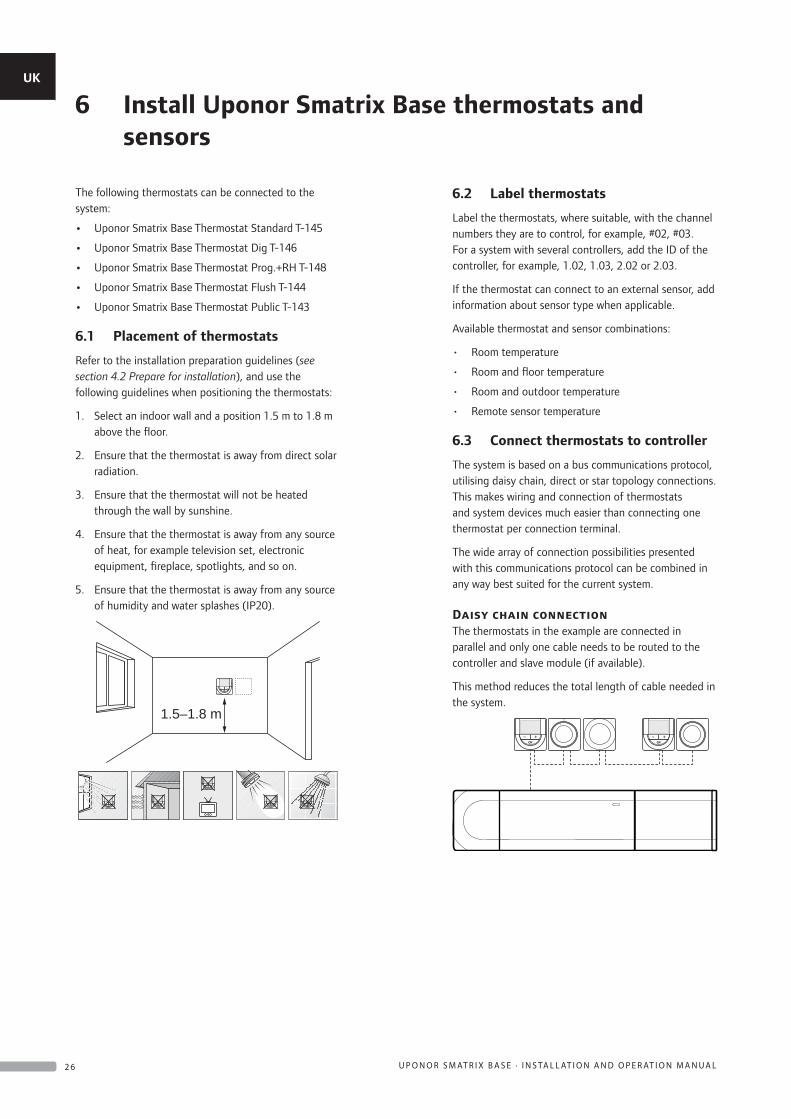
6.1 Placement of thermostats
Refer to the installation preparation guidelines (see section 4.2 Prepare for installation), and use the following guidelines when positioning the thermostats:
1. Select an indoor wall and a position 1.5 m to 1.8 m above the floor.
2. Ensure that the thermostat is away from direct solar radiation.
3. Ensure that the thermostat will not be heated through the wall by sunshine.
4. Ensure that the thermostat is away from any source of heat, for example television set, electronic equipment, fireplace, spotlights, and so on.
5. Ensure that the thermostat is away from any source of humidity and water splashes (IP20).
1.5–1.8 m
6.2 Label thermostats
Label the thermostats, where suitable, with the channel numbers they are to control, for example, #02, #03. For a system with several controllers, add the ID of the controller, for example, 1.02, 1.03, 2.02 or 2.03.
If the thermostat can connect to an external sensor, add information about sensor type when applicable.
Available thermostat and sensor combinations:
• Room temperature
• Room and floor temperature
• Room and outdoor temperature
• Remote sensor temperature
6.3 Connect thermostats to controller
The system is based on a bus communications protocol, utilising daisy chain, direct or star topology connections. This makes wiring and connection of thermostats and system devices much easier than connecting one thermostat per connection terminal.
The wide array of connection possibilities presented with this communications protocol can be combined in any way best suited for the current system.
Daisy chain connectionThe thermostats in the example are connected in parallel and only one cable needs to be routed to the controller and slave module (if available).
This method reduces the total length of cable needed in the system.
UK
CZ
DE
DK
EE
ES
FI
FR
HR
HU
IT
LT
LV
NL
NO
PL
PT
RO
RU
SE
SK
2 6 U P O N O R S M AT R I X B A S E · I N S TA L L AT I O N A N D O P E R AT I O N M A N U A L
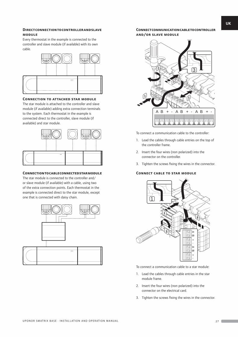
Direct connection to controller and slave moduleEvery thermostat in the example is connected to the controller and slave module (if available) with its own cable.
Connection to attached star moduleThe star module is attached to the controller and slave module (if available) adding extra connection terminals to the system. Each thermostat in the example is connected direct to the controller, slave module (if available) and star module.
Connection to cable connected star moduleThe star module is connected to the controller and/or slave module (if available) with a cable, using two of the extra connection points. Each thermostat in the example is connected direct to the star module, except one that is connected with daisy chain.
Connect communication cable to controller and/or slave module
3
1 1
2
3
+ - + - + -BA BA BA
To connect a communication cable to the controller:
1. Lead the cables through cable entries on the top of the controller frame.
2. Insert the four wires (non polarized) into the connector on the controller.
3. Tighten the screws fixing the wires in the connector.
Connect cable to star module
1
2
3
1
+-
+-
BA
BA
To connect a communication cable to a star module:
1. Lead the cables through cable entries in the star module frame.
2. Insert the four wires (non polarized) into the connector on the electrical card.
3. Tighten the screws fixing the wires in the connector.
UK
CZ
DE
DK
EE
ES
FI
FR
HR
HU
IT
LT
LV
NL
NO
PL
PT
RO
RU
SE
SK
2 7U P O N O R S M AT R I X B A S E · I N S TA L L AT I O N A N D O P E R AT I O N M A N U A L
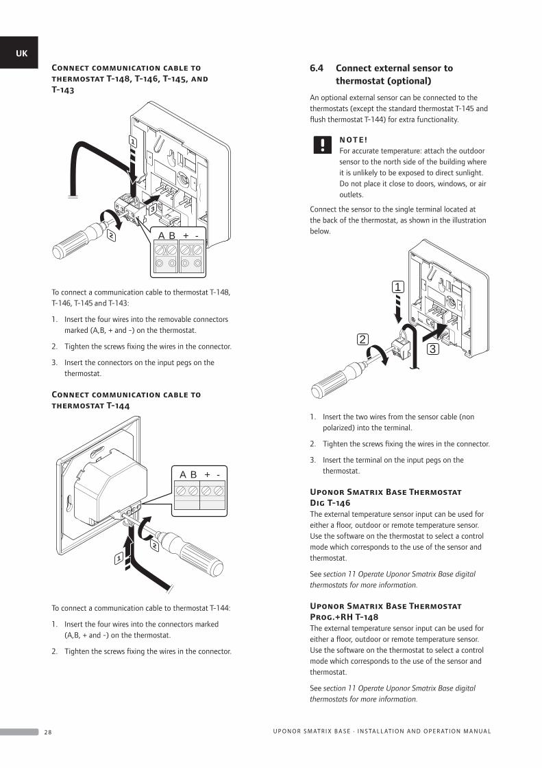
Connect communication cable to thermostat T-148, T-146, T-145, and T-143
2
1
3
A B + -
To connect a communication cable to thermostat T-148, T-146, T-145 and T-143:
1. Insert the four wires into the removable connectors marked (A,B, + and -) on the thermostat.
2. Tighten the screws fixing the wires in the connector.
3. Insert the connectors on the input pegs on the thermostat.
Connect communication cable to thermostat T-144
2
1
A B + -
To connect a communication cable to thermostat T-144:
1. Insert the four wires into the connectors marked (A,B, + and -) on the thermostat.
2. Tighten the screws fixing the wires in the connector.
6.4 Connect external sensor to thermostat (optional)
An optional external sensor can be connected to the thermostats (except the standard thermostat T-145 and flush thermostat T-144) for extra functionality.
N OT E !For accurate temperature: attach the outdoor sensor to the north side of the building where it is unlikely to be exposed to direct sunlight. Do not place it close to doors, windows, or air outlets.
Connect the sensor to the single terminal located at the back of the thermostat, as shown in the illustration below.
1
23
1. Insert the two wires from the sensor cable (non polarized) into the terminal.
2. Tighten the screws fixing the wires in the connector.
3. Insert the terminal on the input pegs on the thermostat.
Uponor Smatrix Base Thermostat Dig T-146The external temperature sensor input can be used for either a floor, outdoor or remote temperature sensor. Use the software on the thermostat to select a control mode which corresponds to the use of the sensor and thermostat.
See section 11 Operate Uponor Smatrix Base digital thermostats for more information.
Uponor Smatrix Base Thermostat Prog.+RH T-148The external temperature sensor input can be used for either a floor, outdoor or remote temperature sensor. Use the software on the thermostat to select a control mode which corresponds to the use of the sensor and thermostat.
See section 11 Operate Uponor Smatrix Base digital thermostats for more information.
UK
CZ
DE
DK
EE
ES
FI
FR
HR
HU
IT
LT
LV
NL
NO
PL
PT
RO
RU
SE
SK
2 8 U P O N O R S M AT R I X B A S E · I N S TA L L AT I O N A N D O P E R AT I O N M A N U A L
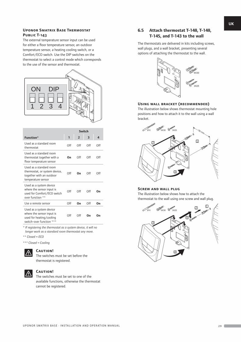
Uponor Smatrix Base Thermostat Public T-143The external temperature sensor input can be used for either a floor temperature sensor, an outdoor temperature sensor, a heating cooling switch, or a Comfort/ECO switch. Use the DIP switches on the thermostat to select a control mode which corresponds to the use of the sensor and thermostat.
1 2 3 4
ON DIP
Function*
Switch
1 2 3 4
Used as a standard room thermostat
Off Off Off Off
Used as a standard room thermostat together with a floor temperature sensor
On Off Off Off
Used as a standard room thermostat, or system device, together with an outdoor temperature sensor
Off On Off Off
Used as a system device where the sensor input is used for Comfort/ECO switch over function **
Off Off Off On
Use a remote sensor Off On Off On
Used as a system device where the sensor input is used for heating/cooling switch-over function ***
Off Off On On
* If registering the thermostat as a system device, it will no longer work as a standard room thermostat any more.
** Closed = ECO
*** Closed = Cooling
Caution!The switches must be set before the thermostat is registered.
Caution!The switches must be set to one of the available functions, otherwise the thermostat cannot be registered.
6.5 Attach thermostat T-148, T-148, T-145, and T-143 to the wall
The thermostats are delivered in kits including screws, wall plugs, and a wall bracket, presenting several options of attaching the thermostat to the wall.
Using wall bracket (recommended)The illustration below shows thermostat mounting hole positions and how to attach it to the wall using a wall bracket.
2 1
3
60 mm
Screw and wall plugThe illustration below shows how to attach the thermostat to the wall using one screw and wall plug.
3
1
5
2
4
UK
CZ
DE
DK
EE
ES
FI
FR
HR
HU
IT
LT
LV
NL
NO
PL
PT
RO
RU
SE
SK
2 9U P O N O R S M AT R I X B A S E · I N S TA L L AT I O N A N D O P E R AT I O N M A N U A L
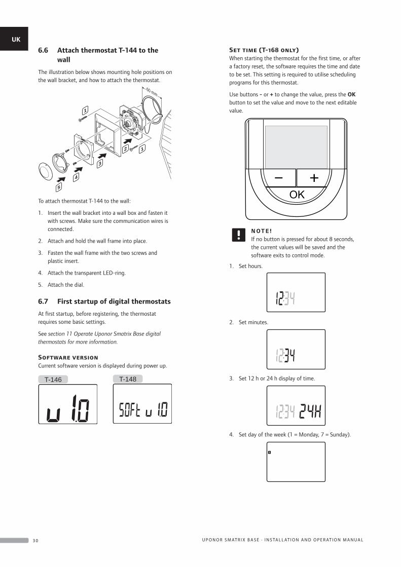
6.6 Attach thermostat T-144 to the wall
The illustration below shows mounting hole positions on the wall bracket, and how to attach the thermostat.
60 mm
2 1
1
3
4
5
To attach thermostat T-144 to the wall:
1. Insert the wall bracket into a wall box and fasten it with screws. Make sure the communication wires is connected.
2. Attach and hold the wall frame into place.
3. Fasten the wall frame with the two screws and plastic insert.
4. Attach the transparent LED-ring.
5. Attach the dial.
6.7 First startup of digital thermostats
At first startup, before registering, the thermostat requires some basic settings.
See section 11 Operate Uponor Smatrix Base digital thermostats for more information.
Software versionCurrent software version is displayed during power up.
T-146 T-148
Set time (T-168 only)When starting the thermostat for the first time, or after a factory reset, the software requires the time and date to be set. This setting is required to utilise scheduling programs for this thermostat.
Use buttons - or + to change the value, press the OK button to set the value and move to the next editable value.
N OT E !If no button is pressed for about 8 seconds, the current values will be saved and the software exits to control mode.
1. Set hours.
2. Set minutes.
3. Set 12 h or 24 h display of time.
4. Set day of the week (1 = Monday, 7 = Sunday).
UK
CZ
DE
DK
EE
ES
FI
FR
HR
HU
IT
LT
LV
NL
NO
PL
PT
RO
RU
SE
SK
3 0 U P O N O R S M AT R I X B A S E · I N S TA L L AT I O N A N D O P E R AT I O N M A N U A L
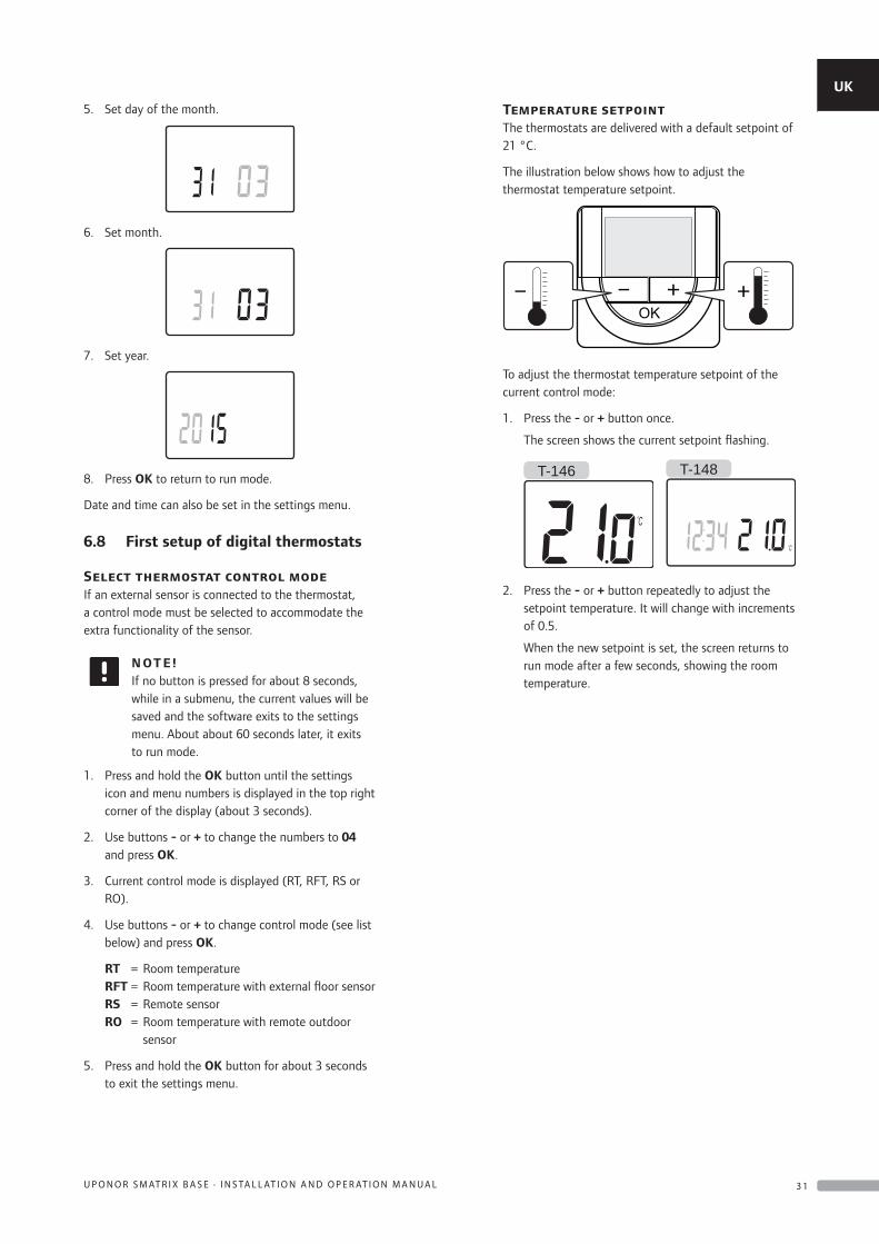
5. Set day of the month.
6. Set month.
7. Set year.
8. Press OK to return to run mode.
Date and time can also be set in the settings menu.
6.8 First setup of digital thermostats
Select thermostat control modeIf an external sensor is connected to the thermostat, a control mode must be selected to accommodate the extra functionality of the sensor.
N OT E !If no button is pressed for about 8 seconds, while in a submenu, the current values will be saved and the software exits to the settings menu. About about 60 seconds later, it exits to run mode.
1. Press and hold the OK button until the settings icon and menu numbers is displayed in the top right corner of the display (about 3 seconds).
2. Use buttons - or + to change the numbers to 04 and press OK.
3. Current control mode is displayed (RT, RFT, RS or RO).
4. Use buttons - or + to change control mode (see list below) and press OK.
RT = Room temperature RFT = Room temperature with external floor sensor RS = Remote sensor RO = Room temperature with remote outdoor
sensor
5. Press and hold the OK button for about 3 seconds to exit the settings menu.
Temperature setpointThe thermostats are delivered with a default setpoint of 21 °C.
The illustration below shows how to adjust the thermostat temperature setpoint.
To adjust the thermostat temperature setpoint of the current control mode:
1. Press the - or + button once.
The screen shows the current setpoint flashing.
T-146 T-148
2. Press the - or + button repeatedly to adjust the setpoint temperature. It will change with increments of 0.5.
When the new setpoint is set, the screen returns to run mode after a few seconds, showing the room temperature.
UK
CZ
DE
DK
EE
ES
FI
FR
HR
HU
IT
LT
LV
NL
NO
PL
PT
RO
RU
SE
SK
3 1U P O N O R S M AT R I X B A S E · I N S TA L L AT I O N A N D O P E R AT I O N M A N U A L
6.9 Register thermostats in controller
Registration at first startupWhen starting the controller for the first time, it automatically enters run mode, which is the standard mode of operation. Go to step 1.
Registration if in run modeRun mode is the standard mode of the controller when the system is running according to set parameters. Go to step 1.
Registration if in forced modeExit to run mode, see section 9.4 Run mode > Exit to run mode, then go to step 1.
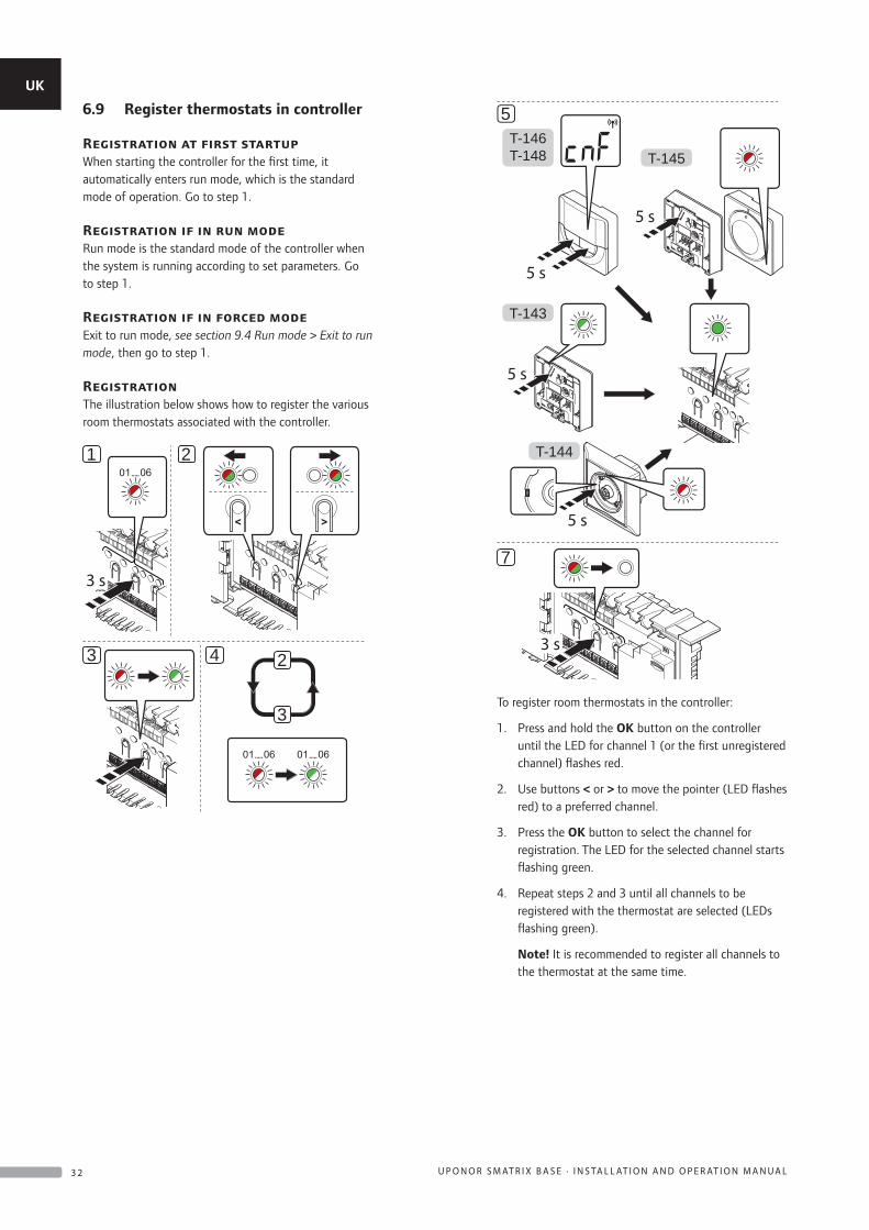
RegistrationThe illustration below shows how to register the various room thermostats associated with the controller.
3 s
21
2
3
3 4
T-146T-148 T-145
T-143
T-144
5 s
5 s
5 s
5 s
5
7
3 s
To register room thermostats in the controller:
1. Press and hold the OK button on the controller until the LED for channel 1 (or the first unregistered channel) flashes red.
2. Use buttons < or > to move the pointer (LED flashes red) to a preferred channel.
3. Press the OK button to select the channel for registration. The LED for the selected channel starts flashing green.
4. Repeat steps 2 and 3 until all channels to be registered with the thermostat are selected (LEDs flashing green).
Note! It is recommended to register all channels to the thermostat at the same time.
UK
CZ
DE
DK
EE
ES
FI
FR
HR
HU
IT
LT
LV
NL
NO
PL
PT
RO
RU
SE
SK
3 2 U P O N O R S M AT R I X B A S E · I N S TA L L AT I O N A N D O P E R AT I O N M A N U A L
5. Thermostat T-143
5.1 Gently press and hold the registration button on the thermostat, release when the LED starts flashing green (located in the hole above the registration button). The selected channel LED in the controller turns fixed green and the registration is complete.
Thermostat T-144
5.1 Using a pointed instrument, gently press and hold the registration button on the thermostat, release when the LED above the dial starts flashing The selected channel LED in the controller turns fixed green and the registration is complete.
Thermostat T-145
5.1 Gently press and hold the registration button on the thermostat, release when the LED on the front of the thermostat starts flashing. The selected channel LED in the controller turns fixed green and the registration is complete.
Thermostats T-146 and T-148
5.1 Press and hold both - and + buttons on the thermostat until the text CnF (configure) and a communication icon is displayed. The selected channel LED in the controller turns fixed green and the registration is complete.
6. Repeat steps 2 through 5 until all used room thermostats are registered.
7. Press and hold the OK button on the controller until the green LEDs turn off to end registration and return to run mode.
To unregister already registered thermostats, see section 9.6 Unregister channels in controller.
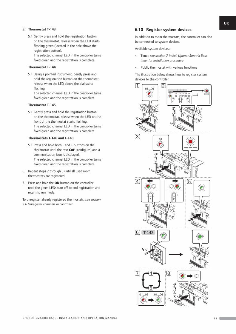
6.10 Register system devices
In addition to room thermostats, the controller can also be connected to system devices.
Available system devices:
• Timer, see section 7 Install Uponor Smatrix Base timer for installation procedure
• Public thermostat with various functions
The illustration below shows how to register system devices to the controller.
3 s
21
3
4 5
T-143
5 s
6
84
6
7
3 s
UK
CZ
DE
DK
EE
ES
FI
FR
HR
HU
IT
LT
LV
NL
NO
PL
PT
RO
RU
SE
SK
3 3U P O N O R S M AT R I X B A S E · I N S TA L L AT I O N A N D O P E R AT I O N M A N U A L
N OT E !Registration of at least one thermostat must be done before registering a system device.
N OT E !If registering a public thermostat T-143 as a system device with various functions, the thermostat only acts as a remote unit. It does not control the room temperature in the room where it is placed.
Caution!The DIP switches in public thermostat T-143 must be set before the thermostat is registered.
Caution!Make sure the controller is in run mode. For information about how to exit to run mode, see section 9.4 Run mode > Exit to run mode.
To register system devices in the controller:
1. Press and hold the OK button on the controller until one of the channel LEDs starts flashing.
2. Use buttons < or > to move the pointer to the power LED (LED flashes red).
3. Press the OK button to select system device registration (power LED). The power LED starts flashing according to the pattern long blink, short pause, long blink. Channel 1 starts flashing red.
4. Use buttons < or > to move the pointer to the preferred system channel, see list below.
1 = Timer See section 7 Install Uponor Smatrix Base timer for more information.
2 = Not used
3 = Public thermostat with outdoor sensor
4 = Public thermostat with heating/cooling switch from contact
5 = Public thermostat with Comfort/ECO switch from contact
5. Press the OK button to select system device channel. The channel LED starts flashing green.
6. Public thermostat T-143 as a system device
6.1 Gently press and hold the registration button on the thermostat, release when the LED starts flashing green (located in the hole above the registration button). The selected channel LED in the controller turns fixed green and the registration is complete.
7. Repeat steps 4 through 6 until all system devices are registered.
8. Press and hold the OK button on the controller until the green LEDs turn off to end registration and return to run mode.
To unregister already registered sensors and switches, see section 9.6 Unregister channels in controller.
UK
CZ
DE
DK
EE
ES
FI
FR
HR
HU
IT
LT
LV
NL
NO
PL
PT
RO
RU
SE
SK
3 4 U P O N O R S M AT R I X B A S E · I N S TA L L AT I O N A N D O P E R AT I O N M A N U A L
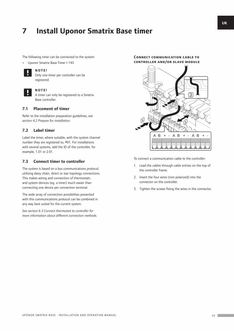
7 Install Uponor Smatrix Base timer
The following timer can be connected to the system:
• Uponor Smatrix Base Timer I-143
N OT E !Only one timer per controller can be registered.
N OT E !A timer can only be registered to a Smatrix Base controller.
7.1 Placement of timer
Refer to the installation preparation guidelines, see section 4.2 Prepare for installation.
7.2 Label timer
Label the timer, where suitable, with the system channel number they are registered to, #01. For installations with several systems, add the ID of the controller, for example, 1.01 or 2.01.
7.3 Connect timer to controller
The system is based on a bus communications protocol, utilising daisy chain, direct or star topology connections. This makes wiring and connection of thermostats and system devices (eg. a timer) much easier than connecting one device per connection terminal.
The wide array of connection possibilities presented with this communications protocol can be combined in any way best suited for the current system.
See section 6.3 Connect thermostat to controller for more information about different connection methods.
Connect communication cable to controller and/or slave module
3
1 1
2
3
+ - + - + -BA BA BA
To connect a communication cable to the controller:
1. Lead the cables through cable entries on the top of the controller frame.
2. Insert the four wires (non polarized) into the connector on the controller.
3. Tighten the screws fixing the wires in the connector.
UK
CZ
DE
DK
EE
ES
FI
FR
HR
HU
IT
LT
LV
NL
NO
PL
PT
RO
RU
SE
SK
3 5U P O N O R S M AT R I X B A S E · I N S TA L L AT I O N A N D O P E R AT I O N M A N U A L
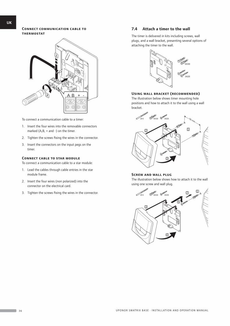
Connect communication cable to thermostat
2
1
3
A B + -
To connect a communication cable to a timer:
1. Insert the four wires into the removable connectors marked (A,B, + and -) on the timer.
2. Tighten the screws fixing the wires in the connector.
3. Insert the connectors on the input pegs on the timer.
Connect cable to star moduleTo connect a communication cable to a star module:
1. Lead the cables through cable entries in the star module frame.
2. Insert the four wires (non polarized) into the connector on the electrical card.
3. Tighten the screws fixing the wires in the connector.
7.4 Attach a timer to the wall
The timer is delivered in kits including screws, wall plugs, and a wall bracket, presenting several options of attaching the timer to the wall.
Using wall bracket (recommended)The illustration below shows timer mounting hole positions and how to attach it to the wall using a wall bracket.
2 1
3
60 mm
Screw and wall plugThe illustration below shows how to attach it to the wall using one screw and wall plug.
3
1
5
2
4
UK
CZ
DE
DK
EE
ES
FI
FR
HR
HU
IT
LT
LV
NL
NO
PL
PT
RO
RU
SE
SK
3 6 U P O N O R S M AT R I X B A S E · I N S TA L L AT I O N A N D O P E R AT I O N M A N U A L
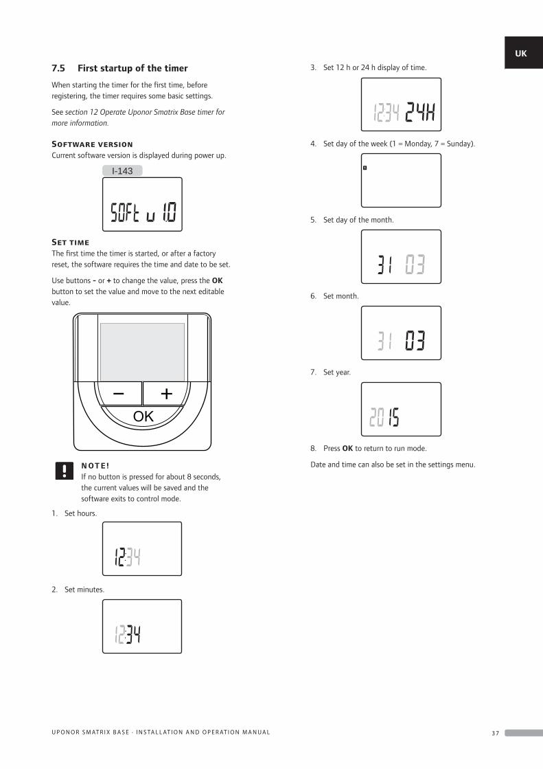
7.5 First startup of the timer
When starting the timer for the first time, before registering, the timer requires some basic settings.
See section 12 Operate Uponor Smatrix Base timer for more information.
Software versionCurrent software version is displayed during power up.
I-143
Set timeThe first time the timer is started, or after a factory reset, the software requires the time and date to be set.
Use buttons - or + to change the value, press the OK button to set the value and move to the next editable value.
N OT E !If no button is pressed for about 8 seconds, the current values will be saved and the software exits to control mode.
1. Set hours.
2. Set minutes.
3. Set 12 h or 24 h display of time.
4. Set day of the week (1 = Monday, 7 = Sunday).
5. Set day of the month.
6. Set month.
7. Set year.
8. Press OK to return to run mode.
Date and time can also be set in the settings menu.
UK
CZ
DE
DK
EE
ES
FI
FR
HR
HU
IT
LT
LV
NL
NO
PL
PT
RO
RU
SE
SK
3 7U P O N O R S M AT R I X B A S E · I N S TA L L AT I O N A N D O P E R AT I O N M A N U A L
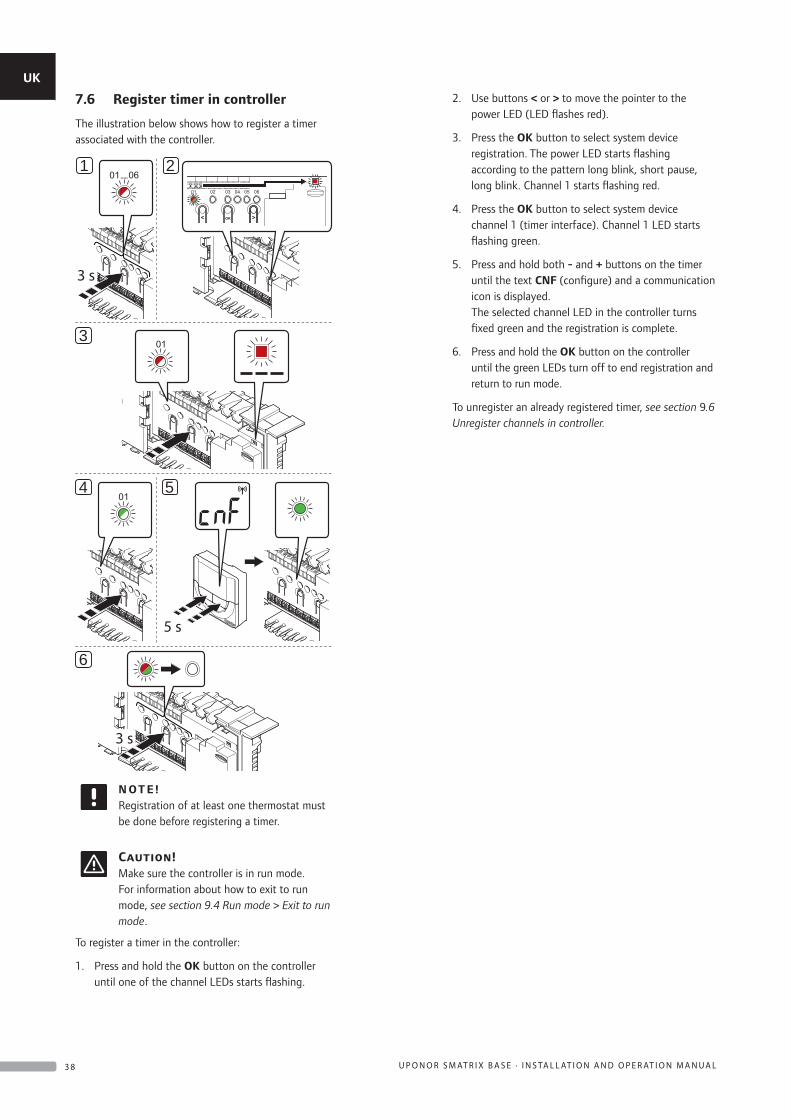
7.6 Register timer in controller
The illustration below shows how to register a timer associated with the controller.
3 s
21
3
4 5
5 s
6
3 s
N OT E !Registration of at least one thermostat must be done before registering a timer.
Caution!Make sure the controller is in run mode. For information about how to exit to run mode, see section 9.4 Run mode > Exit to run mode.
To register a timer in the controller:
1. Press and hold the OK button on the controller until one of the channel LEDs starts flashing.
2. Use buttons < or > to move the pointer to the power LED (LED flashes red).
3. Press the OK button to select system device registration. The power LED starts flashing according to the pattern long blink, short pause, long blink. Channel 1 starts flashing red.
4. Press the OK button to select system device channel 1 (timer interface). Channel 1 LED starts flashing green.
5. Press and hold both - and + buttons on the timer until the text CNF (configure) and a communication icon is displayed. The selected channel LED in the controller turns fixed green and the registration is complete.
6. Press and hold the OK button on the controller until the green LEDs turn off to end registration and return to run mode.
To unregister an already registered timer, see section 9.6 Unregister channels in controller.
UK
CZ
DE
DK
EE
ES
FI
FR
HR
HU
IT
LT
LV
NL
NO
PL
PT
RO
RU
SE
SK
3 8 U P O N O R S M AT R I X B A S E · I N S TA L L AT I O N A N D O P E R AT I O N M A N U A L
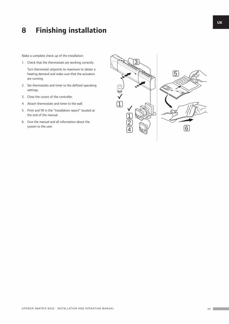
8 Finishing installation
Make a complete check up of the installation:
1. Check that the thermostats are working correctly.
Turn thermostat setpoints to maximum to obtain a heating demand and make sure that the actuators are running.
2. Set thermostats and timer to the defined operating settings.
3. Close the covers of the controller.
4. Attach thermostats and timer to the wall.
5. Print and fill in the “Installation report” located at the end of the manual.
6. Give the manual and all information about the system to the user.
21
1
4
5
6
3
UK
CZ
DE
DK
EE
ES
FI
FR
HR
HU
IT
LT
LV
NL
NO
PL
PT
RO
RU
SE
SK
3 9U P O N O R S M AT R I X B A S E · I N S TA L L AT I O N A N D O P E R AT I O N M A N U A L
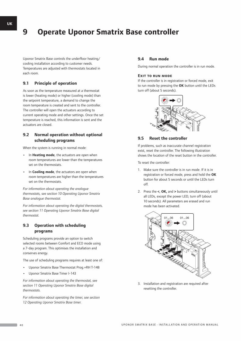
Uponor Smatrix Base controls the underfloor heating/cooling installation according to customer needs. Temperatures are adjusted with thermostats located in each room.
9.1 Principle of operation
As soon as the temperature measured at a thermostat is lower (heating mode) or higher (cooling mode) than the setpoint temperature, a demand to change the room temperature is created and sent to the controller. The controller will open the actuators according to current operating mode and other settings. Once the set temperature is reached, this information is sent and the actuators are closed.
9.2 Normal operation without optional scheduling programs
When the system is running in normal mode:
• In Heating mode, the actuators are open when room temperatures are lower than the temperatures set on the thermostats.
• In Cooling mode, the actuators are open when room temperatures are higher than the temperatures set on the thermostats.
For information about operating the analogue thermostats, see section 10 Operating Uponor Smatrix Base analogue thermostat.
For information about operating the digital thermostats, see section 11 Operating Uponor Smatrix Base digital thermostat.
9.3 Operation with scheduling programs
Scheduling programs provide an option to switch selected rooms between Comfort and ECO mode using a 7-day program. This optimises the installation and conserves energy.
The use of scheduling programs requires at least one of:
• Uponor Smatrix Base Thermostat Prog.+RH T-148
• Uponor Smatrix Base Timer I-143
For information about operating the thermostat, see section 11 Operating Uponor Smatrix Base digital thermostats.
For information about operating the timer, see section 12 Operating Uponor Smatrix Base timer.
9.4 Run mode
During normal operation the controller is in run mode.
Exit to run modeIf the controller is in registration or forced mode, exit to run mode by pressing the OK button until the LEDs turn off (about 5 seconds).
9.5 Reset the controller
If problems, such as inaccurate channel registration exist, reset the controller. The following illustration shows the location of the reset button in the controller.
To reset the controller:
1. Make sure the controller is in run mode. If it is in registration or forced mode, press and hold the OK button for about 5 seconds or until the LEDs turn off.
2. Press the <, OK, and > buttons simultaneously until all LEDs, except the power LED, turn off (about 10 seconds). All parameters are erased and run mode has been activated.
3. Installation and registration are required after resetting the controller.
9 Operate Uponor Smatrix Base controllerUK
CZ
DE
DK
EE
ES
FI
FR
HR
HU
IT
LT
LV
NL
NO
PL
PT
RO
RU
SE
SK
4 0 U P O N O R S M AT R I X B A S E · I N S TA L L AT I O N A N D O P E R AT I O N M A N U A L
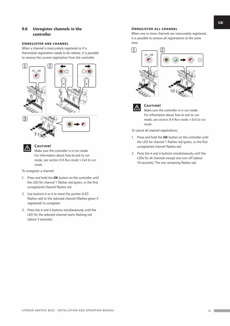
9.6 Unregister channels in the controller
Unregister one channelWhen a channel is inaccurately registered or if a thermostat registration needs to be redone, it is possible to remove the current registration from the controller.
3 s
21
3
Caution!Make sure the controller is in run mode. For information about how to exit to run mode, see section 9.4 Run mode > Exit to run mode.
To unregister a channel:
1. Press and hold the OK button on the controller until the LED for channel 1 flashes red/green, or the first unregistered channel flashes red.
2. Use buttons < or > to move the pointer (LED flashes red) to the selected channel (flashes green if registered) to unregister.
3. Press the < and > buttons simultaneously until the LED for the selected channel starts flashing red (about 3 seconds).
Unregister all channelWhen one or more channels are inaccurately registered, it is possible to remove all registrations at the same time.
10 s
1 2
Caution!Make sure the controller is in run mode. For information about how to exit to run mode, see section 9.4 Run mode > Exit to run mode.
To cancel all channel registrations:
1. Press and hold the OK button on the controller until the LED for channel 1 flashes red/green, or the first unregistered channel flashes red.
2. Press the < and > buttons simultaneously until the LEDs for all channels except one turn off (about 10 seconds). The one remaining flashes red.
UK
CZ
DE
DK
EE
ES
FI
FR
HR
HU
IT
LT
LV
NL
NO
PL
PT
RO
RU
SE
SK
4 1U P O N O R S M AT R I X B A S E · I N S TA L L AT I O N A N D O P E R AT I O N M A N U A L
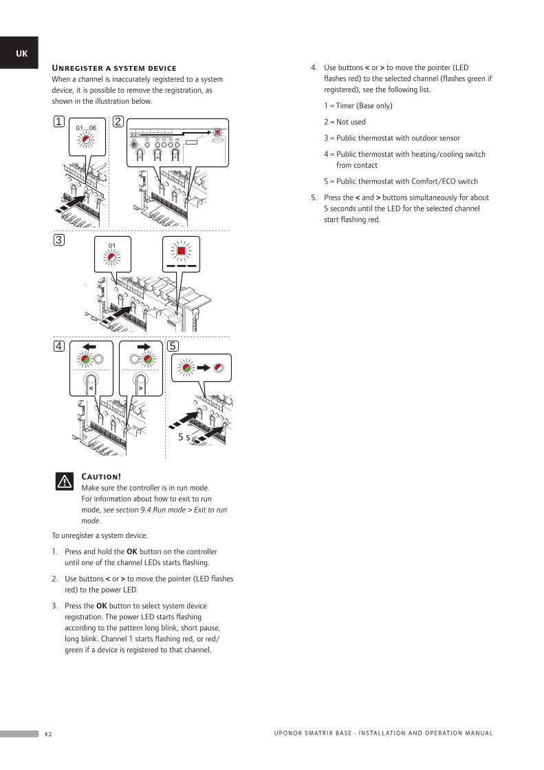
Unregister a system deviceWhen a channel is inaccurately registered to a system device, it is possible to remove the registration, as shown in the illustration below.
5 s
4 5
3
21
Caution!Make sure the controller is in run mode. For information about how to exit to run mode, see section 9.4 Run mode > Exit to run mode.
To unregister a system device:
1. Press and hold the OK button on the controller until one of the channel LEDs starts flashing.
2. Use buttons < or > to move the pointer (LED flashes red) to the power LED.
3. Press the OK button to select system device registration. The power LED starts flashing according to the pattern long blink, short pause, long blink. Channel 1 starts flashing red, or red/green if a device is registered to that channel.
4. Use buttons < or > to move the pointer (LED flashes red) to the selected channel (flashes green if registered), see the following list.
1 = Timer (Base only)
2 = Not used
3 = Public thermostat with outdoor sensor
4 = Public thermostat with heating/cooling switch from contact
5 = Public thermostat with Comfort/ECO switch
5. Press the < and > buttons simultaneously for about 5 seconds until the LED for the selected channel start flashing red.
UK
CZ
DE
DK
EE
ES
FI
FR
HR
HU
IT
LT
LV
NL
NO
PL
PT
RO
RU
SE
SK
4 2 U P O N O R S M AT R I X B A S E · I N S TA L L AT I O N A N D O P E R AT I O N M A N U A L
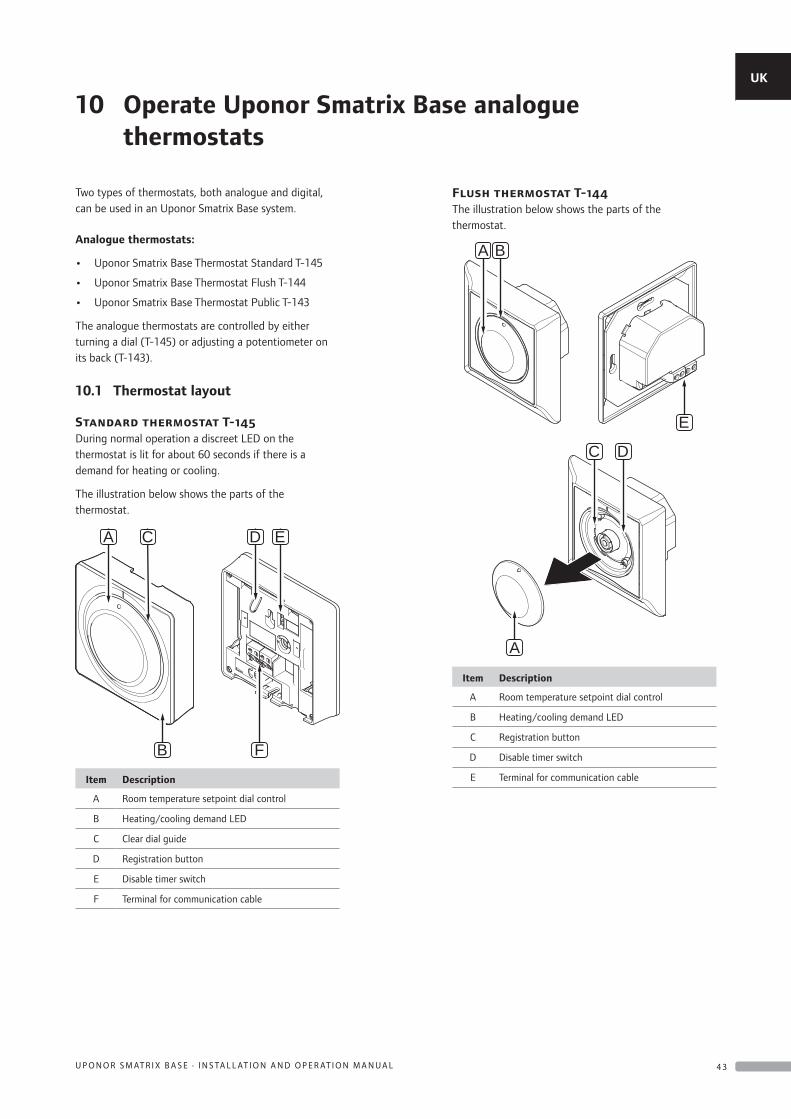
Two types of thermostats, both analogue and digital, can be used in an Uponor Smatrix Base system.
Analogue thermostats:
• Uponor Smatrix Base Thermostat Standard T-145
• Uponor Smatrix Base Thermostat Flush T-144
• Uponor Smatrix Base Thermostat Public T-143
The analogue thermostats are controlled by either turning a dial (T-145) or adjusting a potentiometer on its back (T-143).
10.1 Thermostat layout
Standard thermostat T-145During normal operation a discreet LED on the thermostat is lit for about 60 seconds if there is a demand for heating or cooling.
The illustration below shows the parts of the thermostat.
A C D E
FB
Item Description
A Room temperature setpoint dial control
B Heating/cooling demand LED
C Clear dial guide
D Registration button
E Disable timer switch
F Terminal for communication cable
Flush thermostat T-144The illustration below shows the parts of the thermostat.
A B
E
C D
A
Item Description
A Room temperature setpoint dial control
B Heating/cooling demand LED
C Registration button
D Disable timer switch
E Terminal for communication cable
10 Operate Uponor Smatrix Base analogue thermostats
UK
CZ
DE
DK
EE
ES
FI
FR
HR
HU
IT
LT
LV
NL
NO
PL
PT
RO
RU
SE
SK
4 3U P O N O R S M AT R I X B A S E · I N S TA L L AT I O N A N D O P E R AT I O N M A N U A L
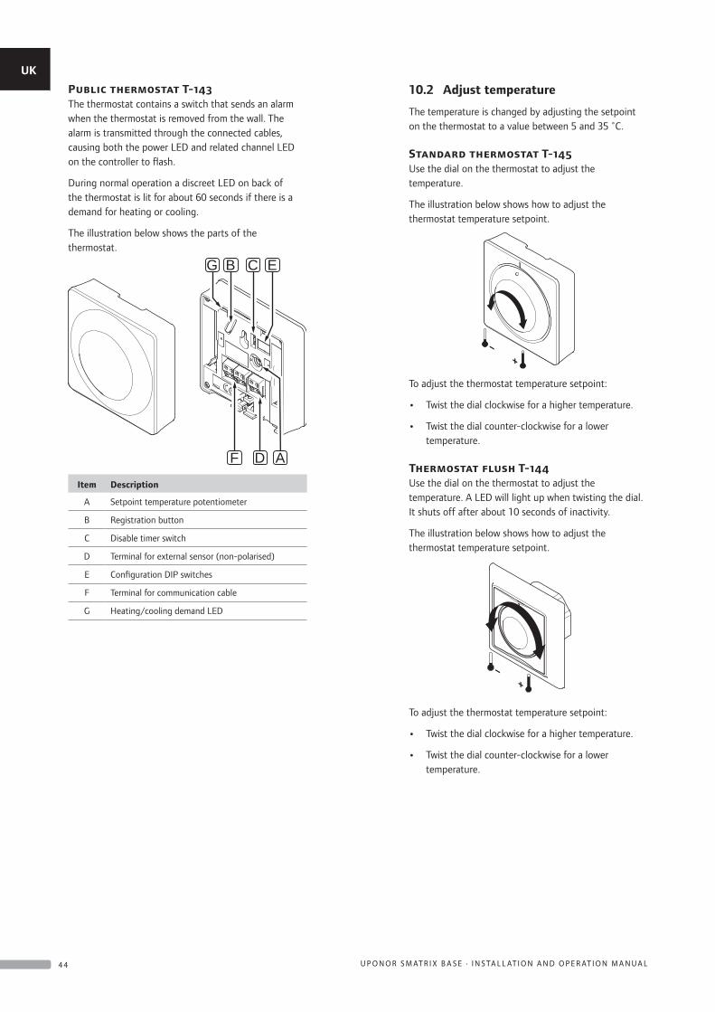
Public thermostat T-143The thermostat contains a switch that sends an alarm when the thermostat is removed from the wall. The alarm is transmitted through the connected cables, causing both the power LED and related channel LED on the controller to flash.
During normal operation a discreet LED on back of the thermostat is lit for about 60 seconds if there is a demand for heating or cooling.
The illustration below shows the parts of the thermostat.
B C E
F D A
G
Item Description
A Setpoint temperature potentiometer
B Registration button
C Disable timer switch
D Terminal for external sensor (non-polarised)
E Configuration DIP switches
F Terminal for communication cable
G Heating/cooling demand LED
10.2 Adjust temperature
The temperature is changed by adjusting the setpoint on the thermostat to a value between 5 and 35 ˚C.
Standard thermostat T-145Use the dial on the thermostat to adjust the temperature.
The illustration below shows how to adjust the thermostat temperature setpoint.
To adjust the thermostat temperature setpoint:
• Twist the dial clockwise for a higher temperature.
• Twist the dial counter-clockwise for a lower temperature.
Thermostat flush T-144Use the dial on the thermostat to adjust the temperature. A LED will light up when twisting the dial. It shuts off after about 10 seconds of inactivity.
The illustration below shows how to adjust the thermostat temperature setpoint.
To adjust the thermostat temperature setpoint:
• Twist the dial clockwise for a higher temperature.
• Twist the dial counter-clockwise for a lower temperature.
UK
CZ
DE
DK
EE
ES
FI
FR
HR
HU
IT
LT
LV
NL
NO
PL
PT
RO
RU
SE
SK
4 4 U P O N O R S M AT R I X B A S E · I N S TA L L AT I O N A N D O P E R AT I O N M A N U A L
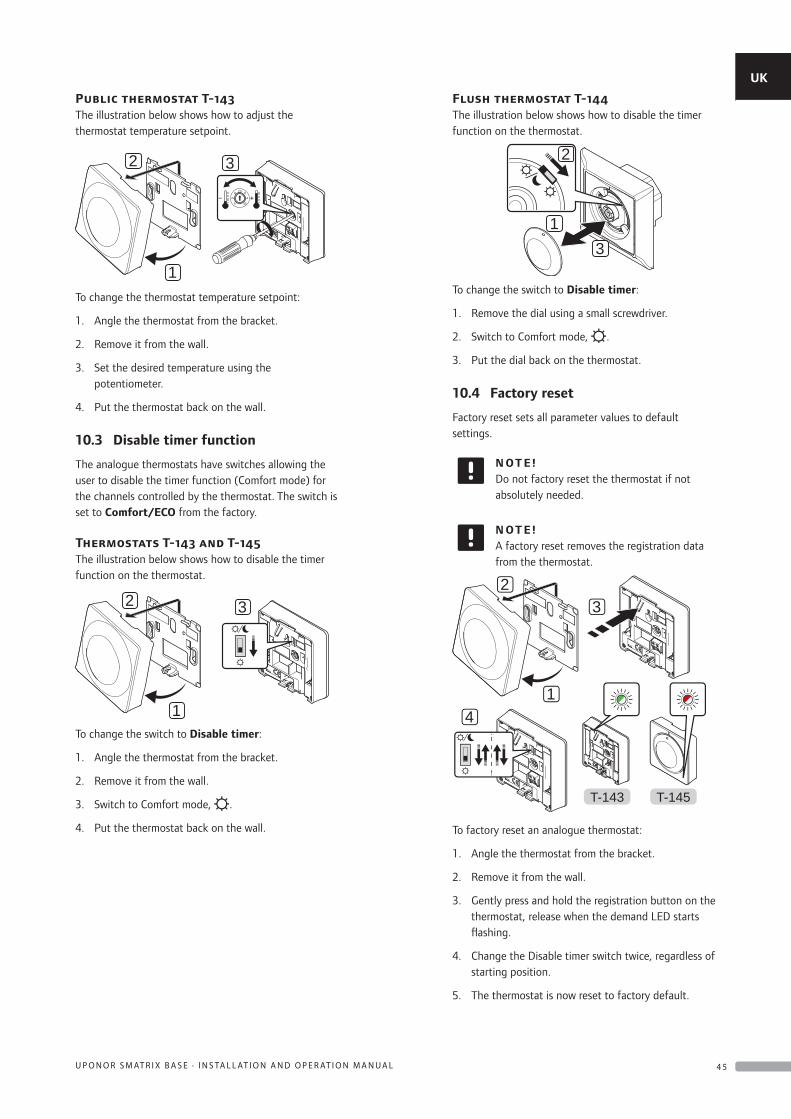
Public thermostat T-143The illustration below shows how to adjust the thermostat temperature setpoint.
2
1
320
5 35
To change the thermostat temperature setpoint:
1. Angle the thermostat from the bracket.
2. Remove it from the wall.
3. Set the desired temperature using the potentiometer.
4. Put the thermostat back on the wall.
10.3 Disable timer function
The analogue thermostats have switches allowing the user to disable the timer function (Comfort mode) for the channels controlled by the thermostat. The switch is set to Comfort/ECO from the factory.
Thermostats T-143 and T-145The illustration below shows how to disable the timer function on the thermostat.
2
1
3
To change the switch to Disable timer:
1. Angle the thermostat from the bracket.
2. Remove it from the wall.
3. Switch to Comfort mode, .
4. Put the thermostat back on the wall.
Flush thermostat T-144The illustration below shows how to disable the timer function on the thermostat.
2
13
To change the switch to Disable timer:
1. Remove the dial using a small screwdriver.
2. Switch to Comfort mode, .
3. Put the dial back on the thermostat.
10.4 Factory reset
Factory reset sets all parameter values to default settings.
N OT E !Do not factory reset the thermostat if not absolutely needed.
N OT E !A factory reset removes the registration data from the thermostat.
2
1
3
4
T-145T-143
To factory reset an analogue thermostat:
1. Angle the thermostat from the bracket.
2. Remove it from the wall.
3. Gently press and hold the registration button on the thermostat, release when the demand LED starts flashing.
4. Change the Disable timer switch twice, regardless of starting position.
5. The thermostat is now reset to factory default.
UK
CZ
DE
DK
EE
ES
FI
FR
HR
HU
IT
LT
LV
NL
NO
PL
PT
RO
RU
SE
SK
4 5U P O N O R S M AT R I X B A S E · I N S TA L L AT I O N A N D O P E R AT I O N M A N U A L
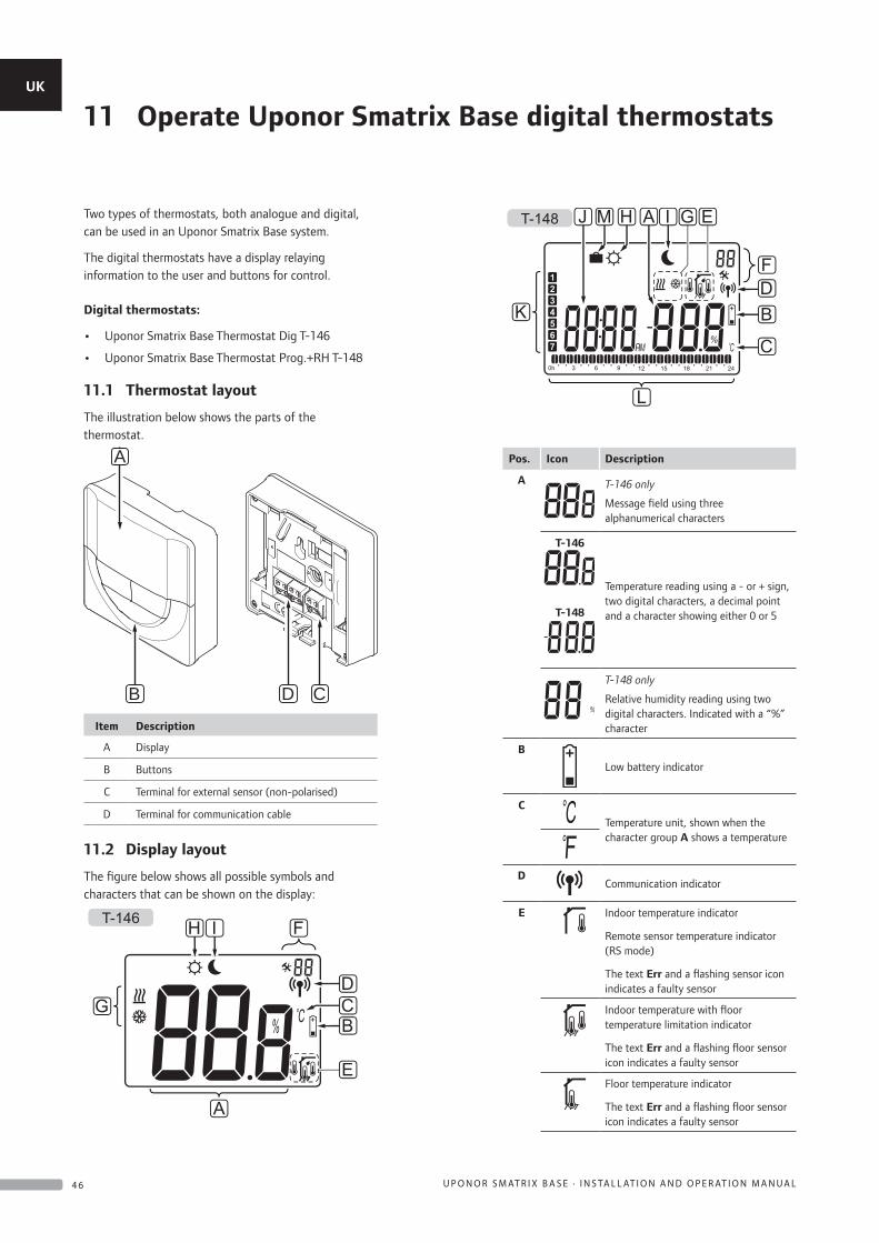
Two types of thermostats, both analogue and digital, can be used in an Uponor Smatrix Base system.
The digital thermostats have a display relaying information to the user and buttons for control.
Digital thermostats:
• Uponor Smatrix Base Thermostat Dig T-146
• Uponor Smatrix Base Thermostat Prog.+RH T-148
11.1 Thermostat layout
The illustration below shows the parts of the thermostat.
D CB
A
Item Description
A Display
B Buttons
C Terminal for external sensor (non-polarised)
D Terminal for communication cable
11.2 Display layout
The figure below shows all possible symbols and characters that can be shown on the display:
A
E
BCD
FH I
G
T-146
L
C
BDF
EG
K
J IAT-148 HM
Pos. Icon Description
A T-146 only
Message field using three alphanumerical characters
T-146
T-148
Temperature reading using a - or + sign, two digital characters, a decimal point and a character showing either 0 or 5
T-148 only
Relative humidity reading using two digital characters. Indicated with a “%” character
B
Low battery indicator
C
Temperature unit, shown when the character group A shows a temperature
DCommunication indicator
E Indoor temperature indicator
Remote sensor temperature indicator (RS mode)
The text Err and a flashing sensor icon indicates a faulty sensor
Indoor temperature with floor temperature limitation indicator
The text Err and a flashing floor sensor icon indicates a faulty sensor
Floor temperature indicator
The text Err and a flashing floor sensor icon indicates a faulty sensor
11 Operate Uponor Smatrix Base digital thermostatsUK
CZ
DE
DK
EE
ES
FI
FR
HR
HU
IT
LT
LV
NL
NO
PL
PT
RO
RU
SE
SK
4 6 U P O N O R S M AT R I X B A S E · I N S TA L L AT I O N A N D O P E R AT I O N M A N U A L
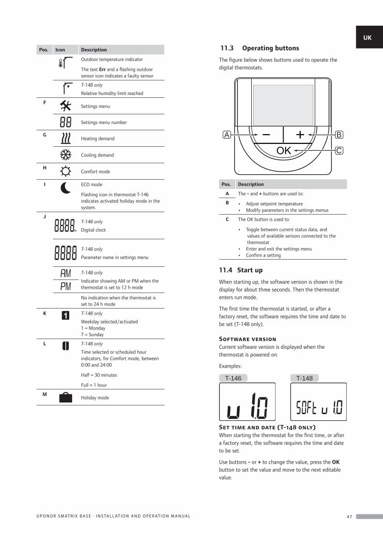
Pos. Icon Description
Outdoor temperature indicator
The text Err and a flashing outdoor sensor icon indicates a faulty sensor
T-148 only
Relative humidity limit reached
FSettings menu
Settings menu number
GHeating demand
Cooling demand
HComfort mode
I ECO mode
Flashing icon in thermostat T-146 indicates activated holiday mode in the system.
JT-148 only
Digital clock
T-148 only
Parameter name in settings menu
T-148 only
Indicator showing AM or PM when the thermostat is set to 12 h mode
No indication when the thermostat is set to 24 h mode
K T-148 only
Weekday selected/activated 1 = Monday 7 = Sunday
L T-148 only
Time selected or scheduled hour indicators, for Comfort mode, between 0:00 and 24:00
Half = 30 minutes
Full = 1 hour
MHoliday mode
11.3 Operating buttons
The figure below shows buttons used to operate the digital thermostats.
B
C
A
Pos. Description
A The - and + buttons are used to:
• Adjust setpoint temperature• Modify parameters in the settings menus
B
C The OK button is used to:
• Toggle between current status data, and values of available sensors connected to the thermostat
• Enter and exit the settings menu• Confirm a setting
11.4 Start up
When starting up, the software version is shown in the display for about three seconds. Then the thermostat enters run mode.
The first time the thermostat is started, or after a factory reset, the software requires the time and date to be set (T-148 only).
Software versionCurrent software version is displayed when the thermostat is powered on.
Examples:
T-146 T-148
Set time and date (T-148 only)When starting the thermostat for the first time, or after a factory reset, the software requires the time and date to be set.
Use buttons - or + to change the value, press the OK button to set the value and move to the next editable value.
UK
CZ
DE
DK
EE
ES
FI
FR
HR
HU
IT
LT
LV
NL
NO
PL
PT
RO
RU
SE
SK
4 7U P O N O R S M AT R I X B A S E · I N S TA L L AT I O N A N D O P E R AT I O N M A N U A L
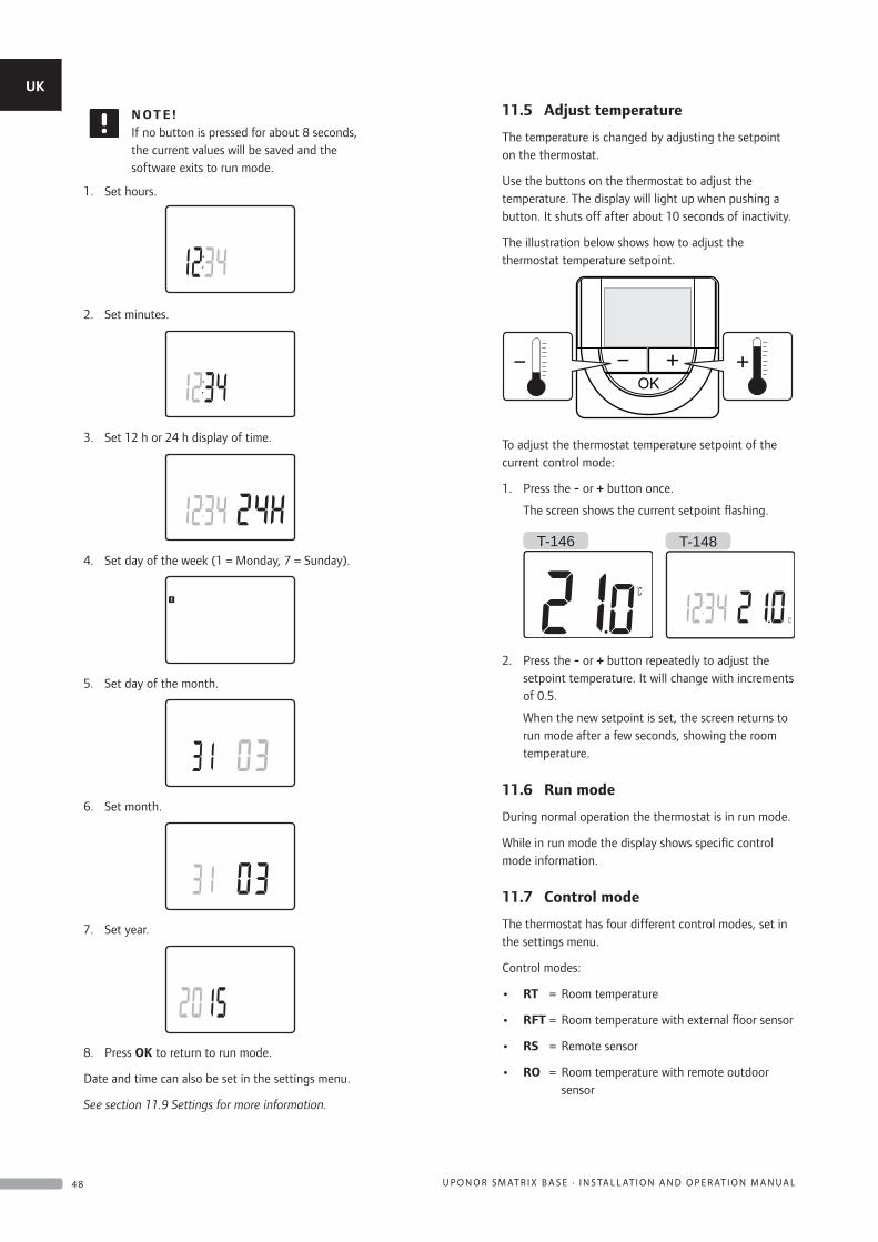
N OT E !If no button is pressed for about 8 seconds, the current values will be saved and the software exits to run mode.
1. Set hours.
2. Set minutes.
3. Set 12 h or 24 h display of time.
4. Set day of the week (1 = Monday, 7 = Sunday).
5. Set day of the month.
6. Set month.
7. Set year.
8. Press OK to return to run mode.
Date and time can also be set in the settings menu.
See section 11.9 Settings for more information.
11.5 Adjust temperature
The temperature is changed by adjusting the setpoint on the thermostat.
Use the buttons on the thermostat to adjust the temperature. The display will light up when pushing a button. It shuts off after about 10 seconds of inactivity.
The illustration below shows how to adjust the thermostat temperature setpoint.
To adjust the thermostat temperature setpoint of the current control mode:
1. Press the - or + button once.
The screen shows the current setpoint flashing.
T-146 T-148
2. Press the - or + button repeatedly to adjust the setpoint temperature. It will change with increments of 0.5.
When the new setpoint is set, the screen returns to run mode after a few seconds, showing the room temperature.
11.6 Run mode
During normal operation the thermostat is in run mode.
While in run mode the display shows specific control mode information.
11.7 Control mode
The thermostat has four different control modes, set in the settings menu.
Control modes:
• RT = Room temperature
• RFT = Room temperature with external floor sensor
• RS = Remote sensor
• RO = Room temperature with remote outdoor sensor
UK
CZ
DE
DK
EE
ES
FI
FR
HR
HU
IT
LT
LV
NL
NO
PL
PT
RO
RU
SE
SK
4 8 U P O N O R S M AT R I X B A S E · I N S TA L L AT I O N A N D O P E R AT I O N M A N U A L
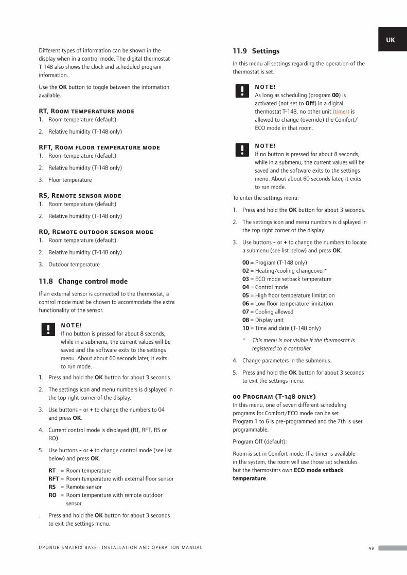
Different types of information can be shown in the display when in a control mode. The digital thermostat T-148 also shows the clock and scheduled program information.
Use the OK button to toggle between the information available.
RT, Room temperature mode1. Room temperature (default)
2. Relative humidity (T-148 only)
RFT, Room floor temperature mode1. Room temperature (default)
2. Relative humidity (T-148 only)
3. Floor temperature
RS, Remote sensor mode1. Room temperature (default)
2. Relative humidity (T-148 only)
RO, Remote outdoor sensor mode1. Room temperature (default)
2. Relative humidity (T-148 only)
3. Outdoor temperature
11.8 Change control mode
If an external sensor is connected to the thermostat, a control mode must be chosen to accommodate the extra functionality of the sensor.
N OT E !If no button is pressed for about 8 seconds, while in a submenu, the current values will be saved and the software exits to the settings menu. About about 60 seconds later, it exits to run mode.
1. Press and hold the OK button for about 3 seconds.
2. The settings icon and menu numbers is displayed in the top right corner of the display.
3. Use buttons - or + to change the numbers to 04 and press OK.
4. Current control mode is displayed (RT, RFT, RS or RO).
5. Use buttons - or + to change control mode (see list below) and press OK.
RT = Room temperature RFT = Room temperature with external floor sensor RS = Remote sensor RO = Room temperature with remote outdoor
sensor
. Press and hold the OK button for about 3 seconds to exit the settings menu.
11.9 Settings
In this menu all settings regarding the operation of the thermostat is set.
N OT E !As long as scheduling (program 00) is activated (not set to Off) in a digital thermostat T-148, no other unit (timer) is allowed to change (override) the Comfort/ECO mode in that room.
N OT E !If no button is pressed for about 8 seconds, while in a submenu, the current values will be saved and the software exits to the settings menu. About about 60 seconds later, it exits to run mode.
To enter the settings menu:
1. Press and hold the OK button for about 3 seconds.
2. The settings icon and menu numbers is displayed in the top right corner of the display.
3. Use buttons - or + to change the numbers to locate a submenu (see list below) and press OK.
00 = Program (T-148 only) 02 = Heating/cooling changeover* 03 = ECO mode setback temperature 04 = Control mode 05 = High floor temperature limitation 06 = Low floor temperature limitation 07 = Cooling allowed 08 = Display unit 10 = Time and date (T-148 only)
* This menu is not visible if the thermostat is registered to a controller.
4. Change parameters in the submenus.
5. Press and hold the OK button for about 3 seconds to exit the settings menu.
00 Program (T-148 only)In this menu, one of seven different scheduling programs for Comfort/ECO mode can be set.Program 1 to 6 is pre-programmed and the 7th is user programmable.
Program Off (default):
Room is set in Comfort mode. If a timer is available in the system, the room will use those set schedules but the thermostats own ECO mode setback temperature.
UK
CZ
DE
DK
EE
ES
FI
FR
HR
HU
IT
LT
LV
NL
NO
PL
PT
RO
RU
SE
SK
4 9U P O N O R S M AT R I X B A S E · I N S TA L L AT I O N A N D O P E R AT I O N M A N U A L
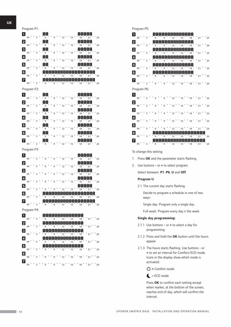
Program P1:
Program P2:
Program P3:
Program P4:
Program P5:
Program P6:
To change this setting:
1. Press OK and the parameter starts flashing.
2. Use buttons - or + to select program.
Select between: P1–P6, U and Off.
Program U
2.1 The current day starts flashing.
Decide to program a schedule in one of two ways:
Single day: Program only a single day.
Full week: Program every day ir the week.
Single day programming:
2.1.1 Use buttons - or + to select a day for programming.
2.1.2 Press and hold the OK button until the hours appear.
2.1.3 The hours starts flashing. Use buttons - or + to set an interval for Comfort/ECO mode. Icons in the display show which mode is activated:
= Comfort mode
= ECO mode
Press OK to confirm each setting except when marker, at the bottom of the screen, reaches end of day, which will confirm the interval.
UK
CZ
DE
DK
EE
ES
FI
FR
HR
HU
IT
LT
LV
NL
NO
PL
PT
RO
RU
SE
SK
5 0 U P O N O R S M AT R I X B A S E · I N S TA L L AT I O N A N D O P E R AT I O N M A N U A L
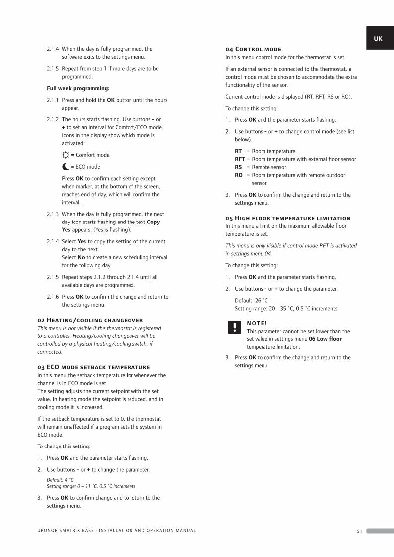
2.1.4 When the day is fully programmed, the software exits to the settings menu.
2.1.5 Repeat from step 1 if more days are to be programmed.
Full week programming:
2.1.1 Press and hold the OK button until the hours appear.
2.1.2 The hours starts flashing. Use buttons - or + to set an interval for Comfort/ECO mode. Icons in the display show which mode is activated:
= Comfort mode
= ECO mode
Press OK to confirm each setting except when marker, at the bottom of the screen, reaches end of day, which will confirm the interval.
2.1.3 When the day is fully programmed, the next day icon starts flashing and the text Copy Yes appears. (Yes is flashing).
2.1.4 Select Yes to copy the setting of the current day to the next. Select No to create a new scheduling interval for the following day.
2.1.5 Repeat steps 2.1.2 through 2.1.4 until all available days are programmed.
2.1.6 Press OK to confirm the change and return to the settings menu.
02 Heating/cooling changeoverThis menu is not visible if the thermostat is registered to a controller. Heating/cooling changeover will be controlled by a physical heating/cooling switch, if connected.
03 ECO mode setback temperatureIn this menu the setback temperature for whenever the channel is in ECO mode is set.The setting adjusts the current setpoint with the set value. In heating mode the setpoint is reduced, and in cooling mode it is increased.
If the setback temperature is set to 0, the thermostat will remain unaffected if a program sets the system in ECO mode.
To change this setting:
1. Press OK and the parameter starts flashing.
2. Use buttons - or + to change the parameter.
Default: 4 ˚C Setting range: 0 – 11 ˚C, 0.5 ˚C increments
3. Press OK to confirm change and to return to the settings menu.
04 Control modeIn this menu control mode for the thermostat is set.
If an external sensor is connected to the thermostat, a control mode must be chosen to accommodate the extra functionality of the sensor.
Current control mode is displayed (RT, RFT, RS or RO).
To change this setting:
1. Press OK and the parameter starts flashing.
2. Use buttons - or + to change control mode (see list below).
RT = Room temperature RFT = Room temperature with external floor sensor RS = Remote sensor RO = Room temperature with remote outdoor
sensor
3. Press OK to confirm the change and return to the settings menu.
05 High floor temperature limitationIn this menu a limit on the maximum allowable floor temperature is set.
This menu is only visible if control mode RFT is activated in settings menu 04.
To change this setting:
1. Press OK and the parameter starts flashing.
2. Use buttons - or + to change the parameter.
Default: 26 ˚C Setting range: 20 – 35 ˚C, 0.5 ˚C increments
N OT E !This parameter cannot be set lower than the set value in settings menu 06 Low floor temperature limitation.
3. Press OK to confirm the change and return to the settings menu.
UK
CZ
DE
DK
EE
ES
FI
FR
HR
HU
IT
LT
LV
NL
NO
PL
PT
RO
RU
SE
SK
5 1U P O N O R S M AT R I X B A S E · I N S TA L L AT I O N A N D O P E R AT I O N M A N U A L
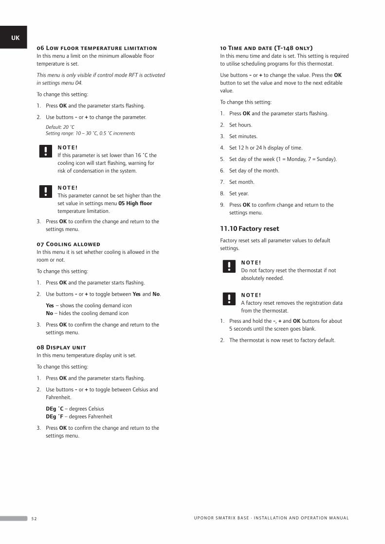
06 Low floor temperature limitationIn this menu a limit on the minimum allowable floor temperature is set.
This menu is only visible if control mode RFT is activated in settings menu 04.
To change this setting:
1. Press OK and the parameter starts flashing.
2. Use buttons - or + to change the parameter.
Default: 20 ˚C Setting range: 10 – 30 ˚C, 0.5 ˚C increments
N OT E !If this parameter is set lower than 16 ˚C the cooling icon will start flashing, warning for risk of condensation in the system.
N OT E !This parameter cannot be set higher than the set value in settings menu 05 High floor temperature limitation.
3. Press OK to confirm the change and return to the settings menu.
07 Cooling allowedIn this menu it is set whether cooling is allowed in the room or not.
To change this setting:
1. Press OK and the parameter starts flashing.
2. Use buttons - or + to toggle between Yes and No.
Yes – shows the cooling demand icon No – hides the cooling demand icon
3. Press OK to confirm the change and return to the settings menu.
08 Display unitIn this menu temperature display unit is set.
To change this setting:
1. Press OK and the parameter starts flashing.
2. Use buttons - or + to toggle between Celsius and Fahrenheit.
DEg ˚C – degrees Celsius DEg ˚F – degrees Fahrenheit
3. Press OK to confirm the change and return to the settings menu.
10 Time and date (T-148 only)In this menu time and date is set. This setting is required to utilise scheduling programs for this thermostat.
Use buttons - or + to change the value. Press the OK button to set the value and move to the next editable value.
To change this setting:
1. Press OK and the parameter starts flashing.
2. Set hours.
3. Set minutes.
4. Set 12 h or 24 h display of time.
5. Set day of the week (1 = Monday, 7 = Sunday).
6. Set day of the month.
7. Set month.
8. Set year.
9. Press OK to confirm change and return to the settings menu.
11.10 Factory reset
Factory reset sets all parameter values to default settings.
N OT E !Do not factory reset the thermostat if not absolutely needed.
N OT E !A factory reset removes the registration data from the thermostat.
1. Press and hold the -, + and OK buttons for about 5 seconds until the screen goes blank.
2. The thermostat is now reset to factory default.
UK
CZ
DE
DK
EE
ES
FI
FR
HR
HU
IT
LT
LV
NL
NO
PL
PT
RO
RU
SE
SK
5 2 U P O N O R S M AT R I X B A S E · I N S TA L L AT I O N A N D O P E R AT I O N M A N U A L
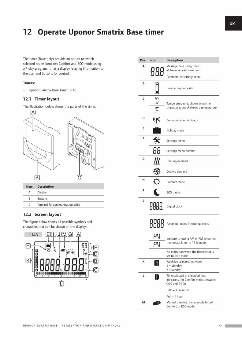
The timer (Base only) provide an option to switch selected rooms between Comfort and ECO mode using a 7-day program. It has a display relaying information to the user and buttons for control.
Timers:
• Uponor Smatrix Base Timer I-143
12.1 Timer layout
The illustration below shows the parts of the timer.
CB
A
Item Description
A Display
B Buttons
C Terminal for communication cable
12.2 Screen layout
The figure below shows all possible symbols and characters that can be shown on the display:
L
C
BDF
G
K
J M AI
H
I-143 E
Pos. Icon Description
A Message field using three alphanumerical characters
Parameter in settings menu
B
Low battery indicator
C
Temperature unit, shown when the character group A shows a temperature
DCommunication indicator
EHoliday mode
FSettings menu
Settings menu number
GHeating demand
Cooling demand
HComfort mode
IECO mode
J
Digital clock
Parameter name in settings menu
Indicator showing AM or PM when the thermostat is set to 12 h mode
No indication when the thermostat is set to 24 h mode
K Weekday selected/activated 1 = Monday 7 = Sunday
L Time selected or sheduled hour indicators, for Comfort mode, between 0:00 and 24:00
Half = 30 minutes
Full = 1 hour
M Manual override. For example forced Comfort or ECO mode.
12 Operate Uponor Smatrix Base timerUK
CZ
DE
DK
EE
ES
FI
FR
HR
HU
IT
LT
LV
NL
NO
PL
PT
RO
RU
SE
SK
5 3U P O N O R S M AT R I X B A S E · I N S TA L L AT I O N A N D O P E R AT I O N M A N U A L
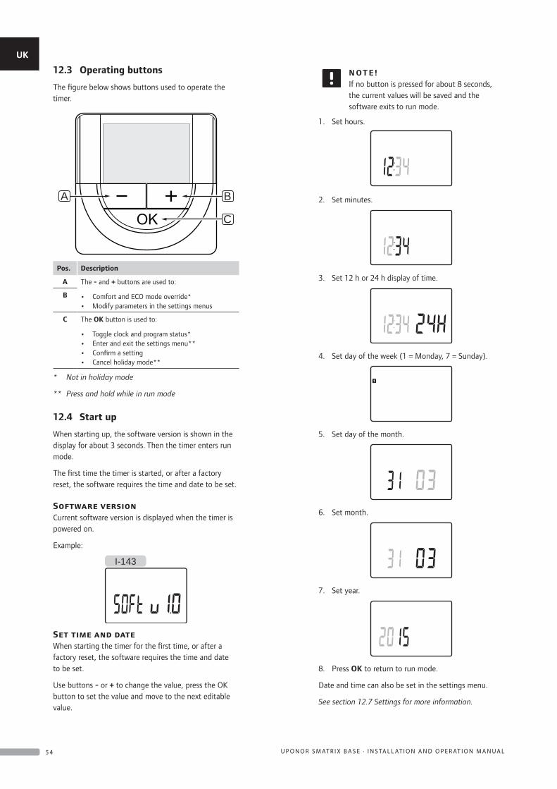
12.3 Operating buttons
The figure below shows buttons used to operate the timer.
B
C
A
Pos. Description
A The - and + buttons are used to:
• Comfort and ECO mode override*• Modify parameters in the settings menus
B
C The OK button is used to:
• Toggle clock and program status*• Enter and exit the settings menu**• Confirm a setting• Cancel holiday mode**
* Not in holiday mode
** Press and hold while in run mode
12.4 Start up
When starting up, the software version is shown in the display for about 3 seconds. Then the timer enters run mode.
The first time the timer is started, or after a factory reset, the software requires the time and date to be set.
Software versionCurrent software version is displayed when the timer is powered on.
Example:
I-143
Set time and dateWhen starting the timer for the first time, or after a factory reset, the software requires the time and date to be set.
Use buttons - or + to change the value, press the OK button to set the value and move to the next editable value.
N OT E !If no button is pressed for about 8 seconds, the current values will be saved and the software exits to run mode.
1. Set hours.
2. Set minutes.
3. Set 12 h or 24 h display of time.
4. Set day of the week (1 = Monday, 7 = Sunday).
5. Set day of the month.
6. Set month.
7. Set year.
8. Press OK to return to run mode.
Date and time can also be set in the settings menu.
See section 12.7 Settings for more information.
UK
CZ
DE
DK
EE
ES
FI
FR
HR
HU
IT
LT
LV
NL
NO
PL
PT
RO
RU
SE
SK
5 4 U P O N O R S M AT R I X B A S E · I N S TA L L AT I O N A N D O P E R AT I O N M A N U A L
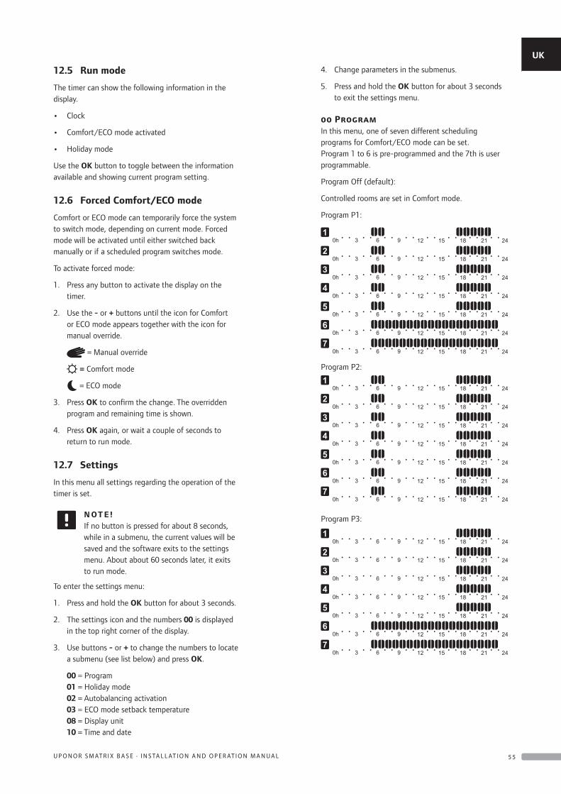
12.5 Run mode
The timer can show the following information in the display.
• Clock
• Comfort/ECO mode activated
• Holiday mode
Use the OK button to toggle between the information available and showing current program setting.
12.6 Forced Comfort/ECO mode
Comfort or ECO mode can temporarily force the system to switch mode, depending on current mode. Forced mode will be activated until either switched back manually or if a scheduled program switches mode.
To activate forced mode:
1. Press any button to activate the display on the timer.
2. Use the - or + buttons until the icon for Comfort or ECO mode appears together with the icon for manual override.
= Manual override
= Comfort mode
= ECO mode
3. Press OK to confirm the change. The overridden program and remaining time is shown.
4. Press OK again, or wait a couple of seconds to return to run mode.
12.7 Settings
In this menu all settings regarding the operation of the timer is set.
N OT E !If no button is pressed for about 8 seconds, while in a submenu, the current values will be saved and the software exits to the settings menu. About about 60 seconds later, it exits to run mode.
To enter the settings menu:
1. Press and hold the OK button for about 3 seconds.
2. The settings icon and the numbers 00 is displayed in the top right corner of the display.
3. Use buttons - or + to change the numbers to locate a submenu (see list below) and press OK.
00 = Program 01 = Holiday mode 02 = Autobalancing activation 03 = ECO mode setback temperature 08 = Display unit 10 = Time and date
4. Change parameters in the submenus.
5. Press and hold the OK button for about 3 seconds to exit the settings menu.
00 ProgramIn this menu, one of seven different scheduling programs for Comfort/ECO mode can be set.Program 1 to 6 is pre-programmed and the 7th is user programmable.
Program Off (default):
Controlled rooms are set in Comfort mode.
Program P1:
Program P2:
Program P3:
UK
CZ
DE
DK
EE
ES
FI
FR
HR
HU
IT
LT
LV
NL
NO
PL
PT
RO
RU
SE
SK
5 5U P O N O R S M AT R I X B A S E · I N S TA L L AT I O N A N D O P E R AT I O N M A N U A L
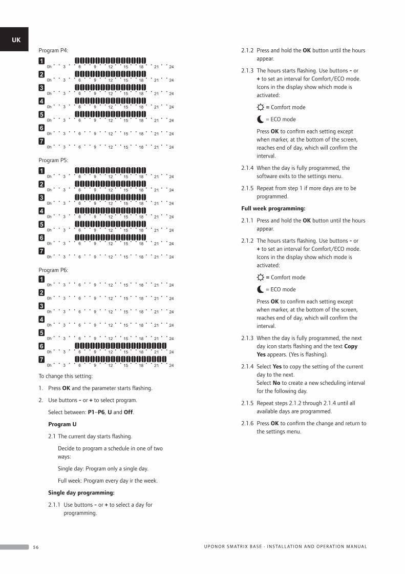
Program P4:
Program P5:
Program P6:
To change this setting:
1. Press OK and the parameter starts flashing.
2. Use buttons - or + to select program.
Select between: P1–P6, U and Off.
Program U
2.1 The current day starts flashing.
Decide to program a schedule in one of two ways:
Single day: Program only a single day.
Full week: Program every day ir the week.
Single day programming:
2.1.1 Use buttons - or + to select a day for programming.
2.1.2 Press and hold the OK button until the hours appear.
2.1.3 The hours starts flashing. Use buttons - or + to set an interval for Comfort/ECO mode. Icons in the display show which mode is activated:
= Comfort mode
= ECO mode
Press OK to confirm each setting except when marker, at the bottom of the screen, reaches end of day, which will confirm the interval.
2.1.4 When the day is fully programmed, the software exits to the settings menu.
2.1.5 Repeat from step 1 if more days are to be programmed.
Full week programming:
2.1.1 Press and hold the OK button until the hours appear.
2.1.2 The hours starts flashing. Use buttons - or + to set an interval for Comfort/ECO mode. Icons in the display show which mode is activated:
= Comfort mode
= ECO mode
Press OK to confirm each setting except when marker, at the bottom of the screen, reaches end of day, which will confirm the interval.
2.1.3 When the day is fully programmed, the next day icon starts flashing and the text Copy Yes appears. (Yes is flashing).
2.1.4 Select Yes to copy the setting of the current day to the next. Select No to create a new scheduling interval for the following day.
2.1.5 Repeat steps 2.1.2 through 2.1.4 until all available days are programmed.
2.1.6 Press OK to confirm the change and return to the settings menu.
UK
CZ
DE
DK
EE
ES
FI
FR
HR
HU
IT
LT
LV
NL
NO
PL
PT
RO
RU
SE
SK
5 6 U P O N O R S M AT R I X B A S E · I N S TA L L AT I O N A N D O P E R AT I O N M A N U A L
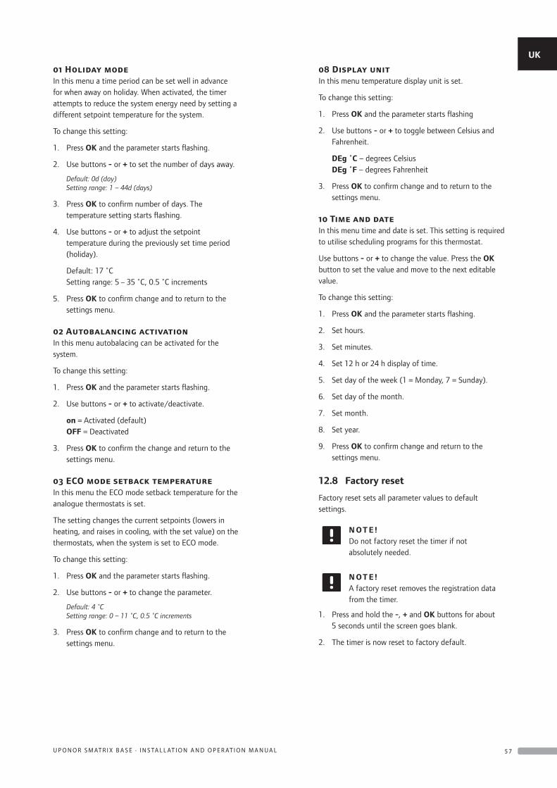
01 Holiday modeIn this menu a time period can be set well in advance for when away on holiday. When activated, the timer attempts to reduce the system energy need by setting a different setpoint temperature for the system.
To change this setting:
1. Press OK and the parameter starts flashing.
2. Use buttons - or + to set the number of days away.
Default: 0d (day) Setting range: 1 – 44d (days)
3. Press OK to confirm number of days. The temperature setting starts flashing.
4. Use buttons - or + to adjust the setpoint temperature during the previously set time period (holiday).
Default: 17 ˚C Setting range: 5 – 35 ˚C, 0.5 ˚C increments
5. Press OK to confirm change and to return to the settings menu.
02 Autobalancing activationIn this menu autobalacing can be activated for the system.
To change this setting:
1. Press OK and the parameter starts flashing.
2. Use buttons - or + to activate/deactivate.
on = Activated (default) OFF = Deactivated
3. Press OK to confirm the change and return to the settings menu.
03 ECO mode setback temperatureIn this menu the ECO mode setback temperature for the analogue thermostats is set.
The setting changes the current setpoints (lowers in heating, and raises in cooling, with the set value) on the thermostats, when the system is set to ECO mode.
To change this setting:
1. Press OK and the parameter starts flashing.
2. Use buttons - or + to change the parameter.
Default: 4 ˚C Setting range: 0 – 11 ˚C, 0.5 ˚C increments
3. Press OK to confirm change and to return to the settings menu.
08 Display unitIn this menu temperature display unit is set.
To change this setting:
1. Press OK and the parameter starts flashing
2. Use buttons - or + to toggle between Celsius and Fahrenheit.
DEg ˚C – degrees Celsius DEg ˚F – degrees Fahrenheit
3. Press OK to confirm change and to return to the settings menu.
10 Time and dateIn this menu time and date is set. This setting is required to utilise scheduling programs for this thermostat.
Use buttons - or + to change the value. Press the OK button to set the value and move to the next editable value.
To change this setting:
1. Press OK and the parameter starts flashing.
2. Set hours.
3. Set minutes.
4. Set 12 h or 24 h display of time.
5. Set day of the week (1 = Monday, 7 = Sunday).
6. Set day of the month.
7. Set month.
8. Set year.
9. Press OK to confirm change and return to the settings menu.
12.8 Factory reset
Factory reset sets all parameter values to default settings.
N OT E !Do not factory reset the timer if not absolutely needed.
N OT E !A factory reset removes the registration data from the timer.
1. Press and hold the -, + and OK buttons for about 5 seconds until the screen goes blank.
2. The timer is now reset to factory default.
UK
CZ
DE
DK
EE
ES
FI
FR
HR
HU
IT
LT
LV
NL
NO
PL
PT
RO
RU
SE
SK
5 7U P O N O R S M AT R I X B A S E · I N S TA L L AT I O N A N D O P E R AT I O N M A N U A L
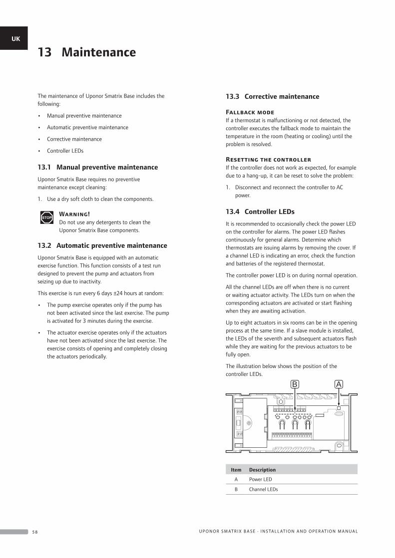
The maintenance of Uponor Smatrix Base includes the following:
• Manual preventive maintenance
• Automatic preventive maintenance
• Corrective maintenance
• Controller LEDs
13.1 Manual preventive maintenance
Uponor Smatrix Base requires no preventive maintenance except cleaning:
1. Use a dry soft cloth to clean the components.
Warning!Do not use any detergents to clean the Uponor Smatrix Base components.
13.2 Automatic preventive maintenance
Uponor Smatrix Base is equipped with an automatic exercise function. This function consists of a test run designed to prevent the pump and actuators from seizing up due to inactivity.
This exercise is run every 6 days ±24 hours at random:
• The pump exercise operates only if the pump has not been activated since the last exercise. The pump is activated for 3 minutes during the exercise.
• The actuator exercise operates only if the actuators have not been activated since the last exercise. The exercise consists of opening and completely closing the actuators periodically.
13.3 Corrective maintenance
Fallback modeIf a thermostat is malfunctioning or not detected, the controller executes the fallback mode to maintain the temperature in the room (heating or cooling) until the problem is resolved.
Resetting the controllerIf the controller does not work as expected, for example due to a hang-up, it can be reset to solve the problem:
1. Disconnect and reconnect the controller to AC power.
13.4 Controller LEDs
It is recommended to occasionally check the power LED on the controller for alarms. The power LED flashes continuously for general alarms. Determine which thermostats are issuing alarms by removing the cover. If a channel LED is indicating an error, check the function and batteries of the registered thermostat.
The controller power LED is on during normal operation.
All the channel LEDs are off when there is no current or waiting actuator activity. The LEDs turn on when the corresponding actuators are activated or start flashing when they are awaiting activation.
Up to eight actuators in six rooms can be in the opening process at the same time. If a slave module is installed, the LEDs of the seventh and subsequent actuators flash while they are waiting for the previous actuators to be fully open.
The illustration below shows the position of the controller LEDs.
B A
Item Description
A Power LED
B Channel LEDs
13 MaintenanceUK
CZ
DE
DK
EE
ES
FI
FR
HR
HU
IT
LT
LV
NL
NO
PL
PT
RO
RU
SE
SK
5 8 U P O N O R S M AT R I X B A S E · I N S TA L L AT I O N A N D O P E R AT I O N M A N U A L
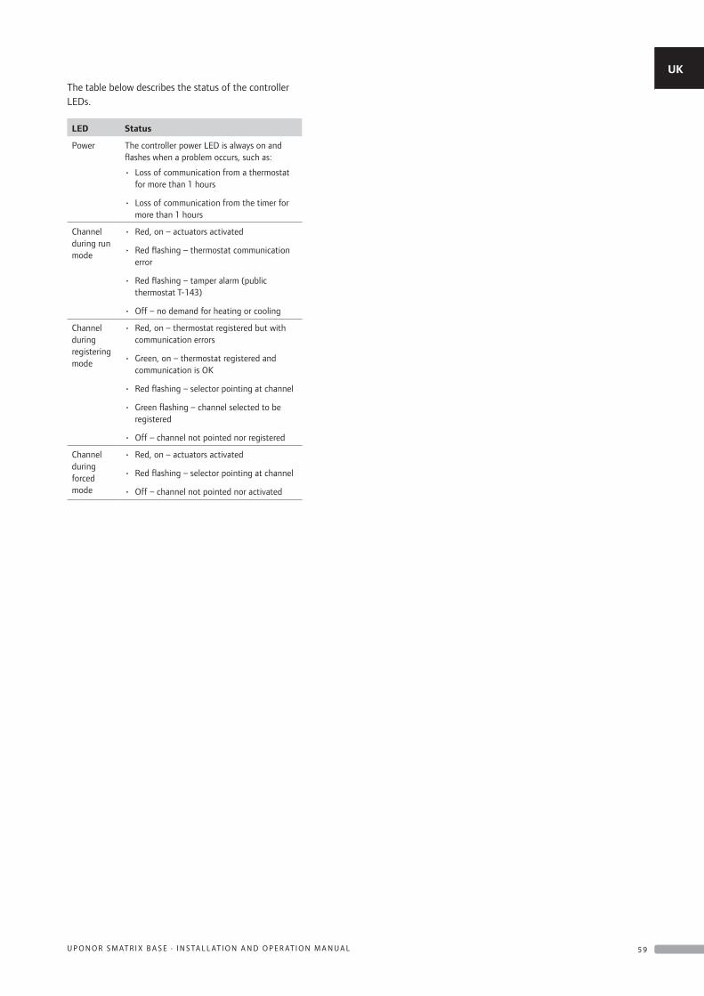
The table below describes the status of the controller LEDs.
LED Status
Power The controller power LED is always on and flashes when a problem occurs, such as:
• Loss of communication from a thermostat for more than 1 hours
• Loss of communication from the timer for more than 1 hours
Channel during run mode
• Red, on – actuators activated
• Red flashing – thermostat communication error
• Red flashing – tamper alarm (public thermostat T-143)
• Off – no demand for heating or cooling
Channel during registering mode
• Red, on – thermostat registered but with communication errors
• Green, on – thermostat registered and communication is OK
• Red flashing – selector pointing at channel
• Green flashing – channel selected to be registered
• Off – channel not pointed nor registered
Channel during forced mode
• Red, on – actuators activated
• Red flashing – selector pointing at channel
• Off – channel not pointed nor activated
UK
CZ
DE
DK
EE
ES
FI
FR
HR
HU
IT
LT
LV
NL
NO
PL
PT
RO
RU
SE
SK
5 9U P O N O R S M AT R I X B A S E · I N S TA L L AT I O N A N D O P E R AT I O N M A N U A L
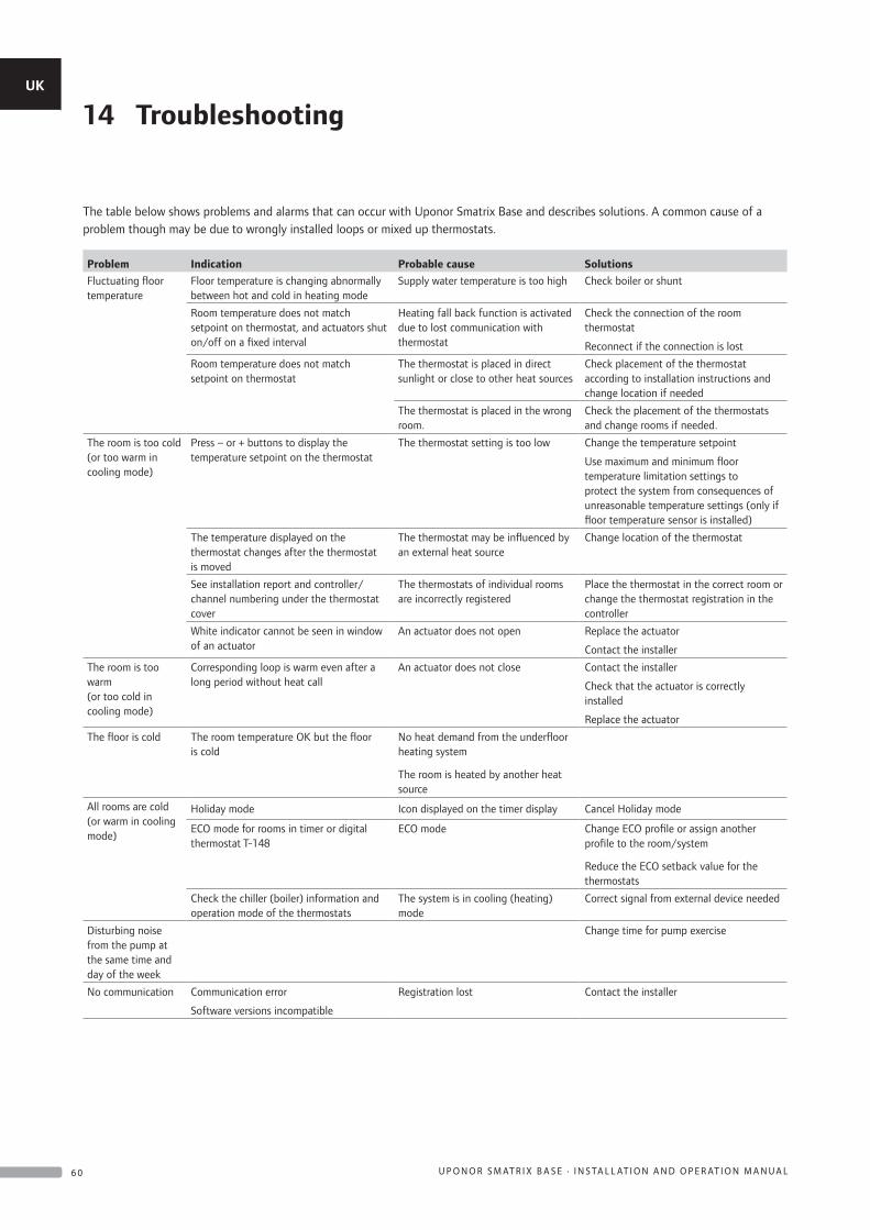
The table below shows problems and alarms that can occur with Uponor Smatrix Base and describes solutions. A common cause of a problem though may be due to wrongly installed loops or mixed up thermostats.
Problem Indication Probable cause Solutions
Fluctuating floor temperature
Floor temperature is changing abnormally between hot and cold in heating mode
Supply water temperature is too high Check boiler or shunt
Room temperature does not match setpoint on thermostat, and actuators shut on/off on a fixed interval
Heating fall back function is activated due to lost communication with thermostat
Check the connection of the room thermostat
Reconnect if the connection is lost
Room temperature does not match setpoint on thermostat
The thermostat is placed in direct sunlight or close to other heat sources
Check placement of the thermostat according to installation instructions and change location if needed
The thermostat is placed in the wrong room.
Check the placement of the thermostats and change rooms if needed.
The room is too cold (or too warm in cooling mode)
Press – or + buttons to display the temperature setpoint on the thermostat
The thermostat setting is too low Change the temperature setpoint
Use maximum and minimum floor temperature limitation settings to protect the system from consequences of unreasonable temperature settings (only if floor temperature sensor is installed)
The temperature displayed on the thermostat changes after the thermostat is moved
The thermostat may be influenced by an external heat source
Change location of the thermostat
See installation report and controller/channel numbering under the thermostat cover
The thermostats of individual rooms are incorrectly registered
Place the thermostat in the correct room or change the thermostat registration in the controller
White indicator cannot be seen in window of an actuator
An actuator does not open Replace the actuator
Contact the installer
The room is too warm (or too cold in cooling mode)
Corresponding loop is warm even after a long period without heat call
An actuator does not close Contact the installer
Check that the actuator is correctly installed
Replace the actuator
The floor is cold The room temperature OK but the floor is cold
No heat demand from the underfloor heating system
The room is heated by another heat source
All rooms are cold (or warm in cooling mode)
Holiday mode Icon displayed on the timer display Cancel Holiday mode
ECO mode for rooms in timer or digital thermostat T-148
ECO mode Change ECO profile or assign another profile to the room/system
Reduce the ECO setback value for the thermostats
Check the chiller (boiler) information and operation mode of the thermostats
The system is in cooling (heating) mode
Correct signal from external device needed
Disturbing noise from the pump at the same time and day of the week
Change time for pump exercise
No communication Communication error
Software versions incompatible
Registration lost Contact the installer
14 TroubleshootingUK
CZ
DE
DK
EE
ES
FI
FR
HR
HU
IT
LT
LV
NL
NO
PL
PT
RO
RU
SE
SK
6 0 U P O N O R S M AT R I X B A S E · I N S TA L L AT I O N A N D O P E R AT I O N M A N U A L
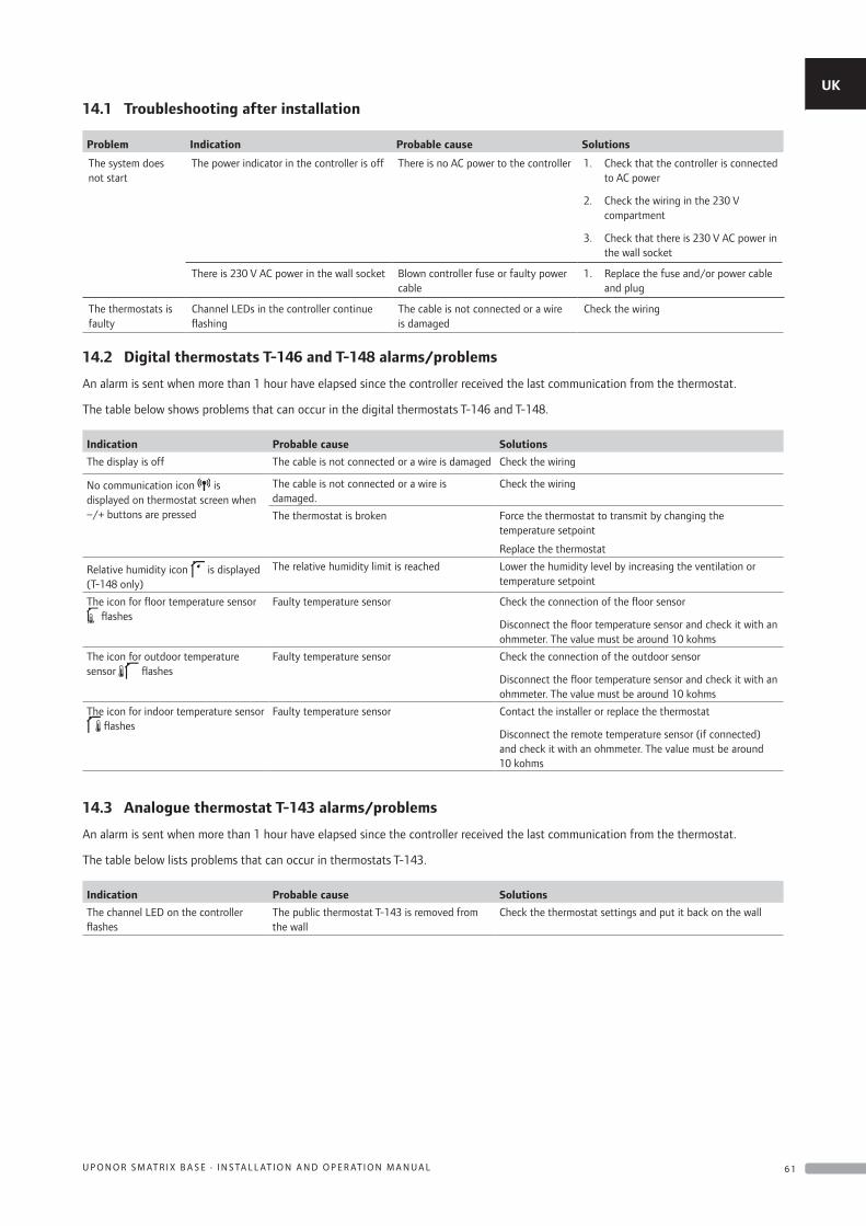
14.1 Troubleshooting after installation
Problem Indication Probable cause Solutions
The system does not start
The power indicator in the controller is off There is no AC power to the controller 1. Check that the controller is connected to AC power
2. Check the wiring in the 230 V compartment
3. Check that there is 230 V AC power in the wall socket
There is 230 V AC power in the wall socket Blown controller fuse or faulty power cable
1. Replace the fuse and/or power cable and plug
The thermostats is faulty
Channel LEDs in the controller continue flashing
The cable is not connected or a wire is damaged
Check the wiring
14.2 Digital thermostats T-146 and T-148 alarms/problems
An alarm is sent when more than 1 hour have elapsed since the controller received the last communication from the thermostat.
The table below shows problems that can occur in the digital thermostats T-146 and T-148.
Indication Probable cause Solutions
The display is off The cable is not connected or a wire is damaged Check the wiring
No communication icon is displayed on thermostat screen when –/+ buttons are pressed
The cable is not connected or a wire is damaged.
Check the wiring
The thermostat is broken Force the thermostat to transmit by changing the temperature setpoint
Replace the thermostat
Relative humidity icon is displayed (T-148 only)
The relative humidity limit is reached Lower the humidity level by increasing the ventilation or temperature setpoint
The icon for floor temperature sensor flashes
Faulty temperature sensor Check the connection of the floor sensor
Disconnect the floor temperature sensor and check it with an ohmmeter. The value must be around 10 kohms
The icon for outdoor temperature sensor flashes
Faulty temperature sensor Check the connection of the outdoor sensor
Disconnect the floor temperature sensor and check it with an ohmmeter. The value must be around 10 kohms
The icon for indoor temperature sensor flashes
Faulty temperature sensor Contact the installer or replace the thermostat
Disconnect the remote temperature sensor (if connected) and check it with an ohmmeter. The value must be around 10 kohms
14.3 Analogue thermostat T-143 alarms/problems
An alarm is sent when more than 1 hour have elapsed since the controller received the last communication from the thermostat.
The table below lists problems that can occur in thermostats T-143.
Indication Probable cause Solutions
The channel LED on the controller flashes
The public thermostat T-143 is removed from the wall
Check the thermostat settings and put it back on the wall
UK
CZ
DE
DK
EE
ES
FI
FR
HR
HU
IT
LT
LV
NL
NO
PL
PT
RO
RU
SE
SK
6 1U P O N O R S M AT R I X B A S E · I N S TA L L AT I O N A N D O P E R AT I O N M A N U A L
14.4 Contact the installer
For installer contact information, see the installation report in the end of this document. Prepare the following information before contacting an installer:
• Installation report
• Drawings of the underfloor heating system (if available)
• List of all alarms, including time and date
14.5 Installer instructions
To determine if a problem is caused by the supply system or the control system, loosen the actuators from the manifold for the room concerned, wait a few minutes and check if the flow pipe of the underfloor heating loop becomes warm.
If the pipe does not become warm, the problem is in the heating system. If the loop becomes warm, the cause could be the room control system.
A supply system defect can be indicated by no warm water in the manifold. Check the boiler and circulation pump.
UK
CZ
DE
DK
EE
ES
FI
FR
HR
HU
IT
LT
LV
NL
NO
PL
PT
RO
RU
SE
SK
6 2 U P O N O R S M AT R I X B A S E · I N S TA L L AT I O N A N D O P E R AT I O N M A N U A L
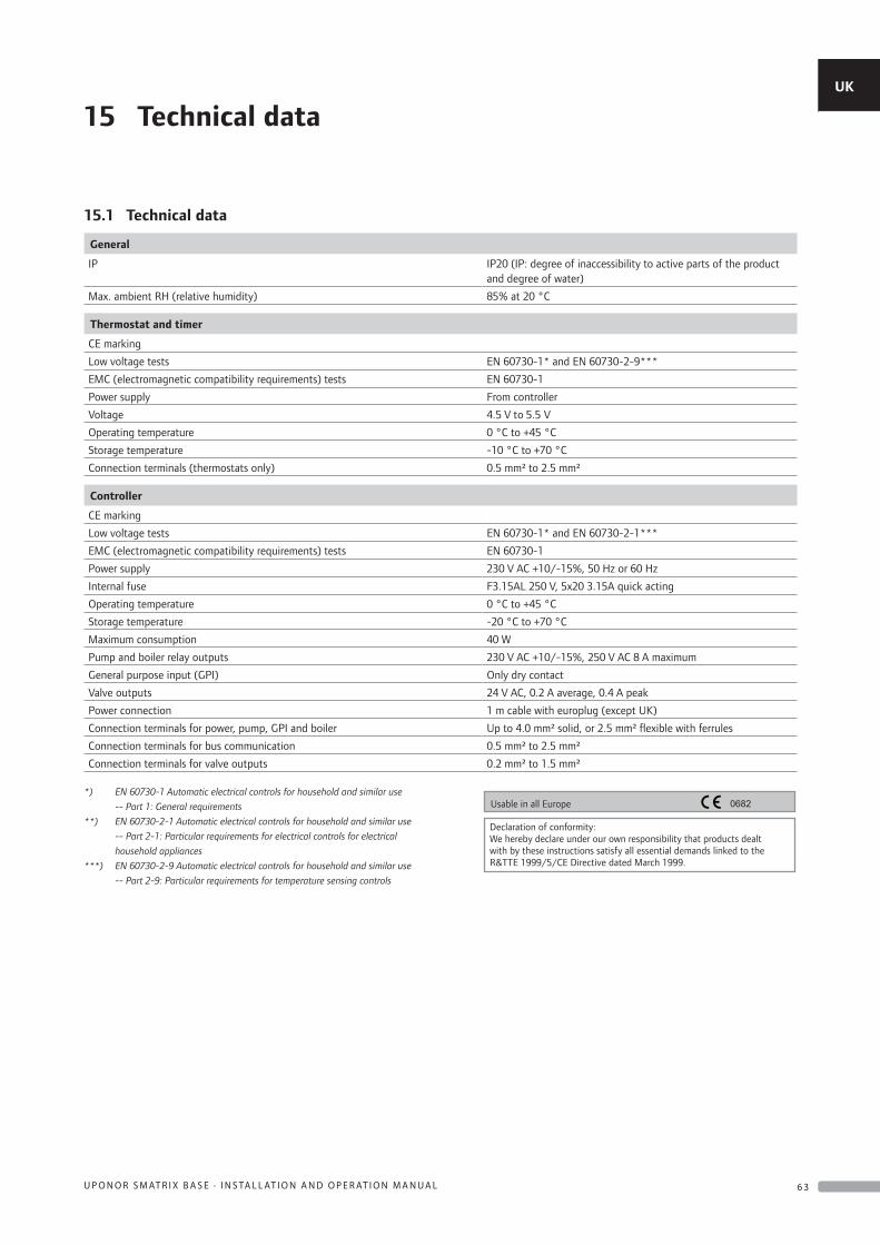
15 Technical data
15.1 Technical data
General
IP IP20 (IP: degree of inaccessibility to active parts of the product and degree of water)
Max. ambient RH (relative humidity) 85% at 20 °C
Thermostat and timer
CE marking
Low voltage tests EN 60730-1* and EN 60730-2-9***
EMC (electromagnetic compatibility requirements) tests EN 60730-1
Power supply From controller
Voltage 4.5 V to 5.5 V
Operating temperature 0 °C to +45 °C
Storage temperature -10 °C to +70 °C
Connection terminals (thermostats only) 0.5 mm² to 2.5 mm²
Controller
CE marking
Low voltage tests EN 60730-1* and EN 60730-2-1***
EMC (electromagnetic compatibility requirements) tests EN 60730-1
Power supply 230 V AC +10/-15%, 50 Hz or 60 Hz
Internal fuse F3.15AL 250 V, 5x20 3.15A quick acting
Operating temperature 0 °C to +45 °C
Storage temperature -20 °C to +70 °C
Maximum consumption 40 W
Pump and boiler relay outputs 230 V AC +10/-15%, 250 V AC 8 A maximum
General purpose input (GPI) Only dry contact
Valve outputs 24 V AC, 0.2 A average, 0.4 A peak
Power connection 1 m cable with europlug (except UK)
Connection terminals for power, pump, GPI and boiler Up to 4.0 mm² solid, or 2.5 mm² flexible with ferrules
Connection terminals for bus communication 0.5 mm² to 2.5 mm²
Connection terminals for valve outputs 0.2 mm² to 1.5 mm²
*) EN 60730-1 Automatic electrical controls for household and similar use
-- Part 1: General requirements
**) EN 60730-2-1 Automatic electrical controls for household and similar use
-- Part 2-1: Particular requirements for electrical controls for electrical
household appliances
***) EN 60730-2-9 Automatic electrical controls for household and similar use
-- Part 2-9: Particular requirements for temperature sensing controls
0682Usable in all Europe
Declaration of conformity:We hereby declare under our own responsibility that products dealt with by these instructions satisfy all essential demands linked to the R&TTE 1999/5/CE Directive dated March 1999.
UK
CZ
DE
DK
EE
ES
FI
FR
HR
HU
IT
LT
LV
NL
NO
PL
PT
RO
RU
SE
SK
6 3U P O N O R S M AT R I X B A S E · I N S TA L L AT I O N A N D O P E R AT I O N M A N U A L
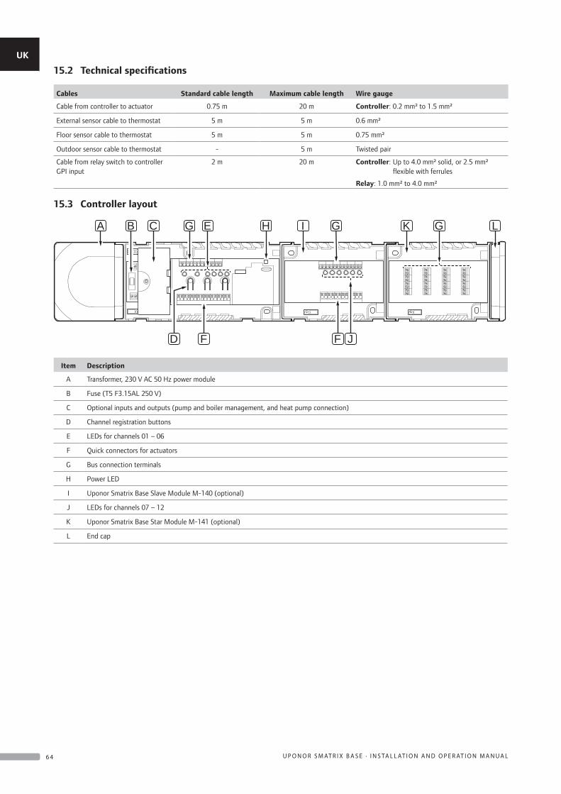
15.2 Technical specifications
Cables Standard cable length Maximum cable length Wire gauge
Cable from controller to actuator 0.75 m 20 m Controller: 0.2 mm² to 1.5 mm²
External sensor cable to thermostat 5 m 5 m 0.6 mm²
Floor sensor cable to thermostat 5 m 5 m 0.75 mm²
Outdoor sensor cable to thermostat - 5 m Twisted pair
Cable from relay switch to controller GPI input
2 m 20 m Controller: Up to 4.0 mm² solid, or 2.5 mm² flexible with ferrules
Relay: 1.0 mm² to 4.0 mm²
15.3 Controller layout
E HG G GI K
F F JD
CB LA
Item Description
A Transformer, 230 V AC 50 Hz power module
B Fuse (T5 F3.15AL 250 V)
C Optional inputs and outputs (pump and boiler management, and heat pump connection)
D Channel registration buttons
E LEDs for channels 01 – 06
F Quick connectors for actuators
G Bus connection terminals
H Power LED
I Uponor Smatrix Base Slave Module M-140 (optional)
J LEDs for channels 07 – 12
K Uponor Smatrix Base Star Module M-141 (optional)
L End cap
UK
CZ
DE
DK
EE
ES
FI
FR
HR
HU
IT
LT
LV
NL
NO
PL
PT
RO
RU
SE
SK
6 4 U P O N O R S M AT R I X B A S E · I N S TA L L AT I O N A N D O P E R AT I O N M A N U A L
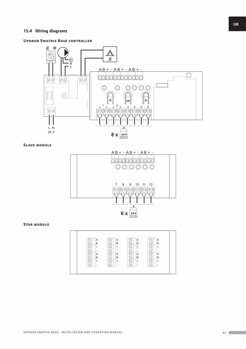
15.4 Wiring diagrams
Uponor Smatrix Base controller
A B + - A B + - A B + -
Slave module
A B + - A B + - A B + -
Star module
AB+-AB+-
AB+-AB+-
AB+-AB+-
AB+-AB+-
UK
CZ
DE
DK
EE
ES
FI
FR
HR
HU
IT
LT
LV
NL
NO
PL
PT
RO
RU
SE
SK
6 5U P O N O R S M AT R I X B A S E · I N S TA L L AT I O N A N D O P E R AT I O N M A N U A L
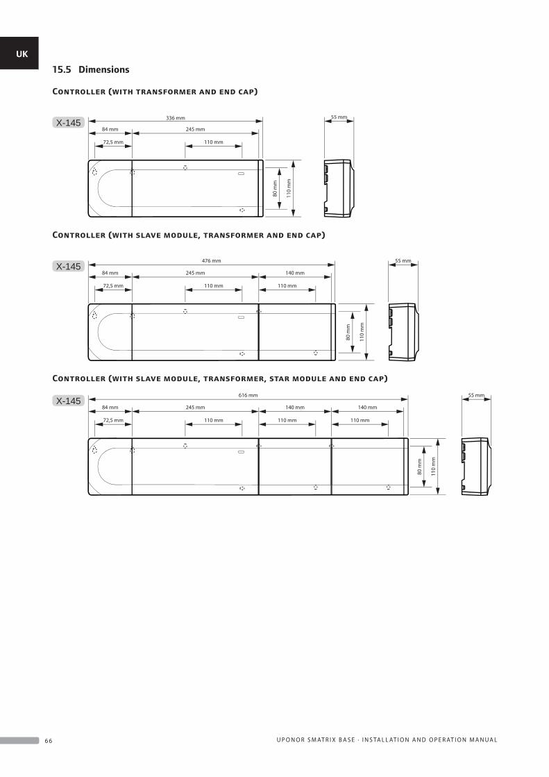
15.5 Dimensions
Controller (with transformer and end cap)
X-145336 mm
245 mm84 mm
72,5 mm 110 mm
110
mm
80 m
m
55 mm
Controller (with slave module, transformer and end cap)
X-145476 mm
110
mm
80 m
m
245 mm 140 mm84 mm
72,5 mm 110 mm 110 mm
55 mm
Controller (with slave module, transformer, star module and end cap)
X-145
110
mm
80 m
m
245 mm 140 mm84 mm
72,5 mm 110 mm 110 mm
140 mm
110 mm
55 mm616 mm
UK
CZ
DE
DK
EE
ES
FI
FR
HR
HU
IT
LT
LV
NL
NO
PL
PT
RO
RU
SE
SK
6 6 U P O N O R S M AT R I X B A S E · I N S TA L L AT I O N A N D O P E R AT I O N M A N U A L
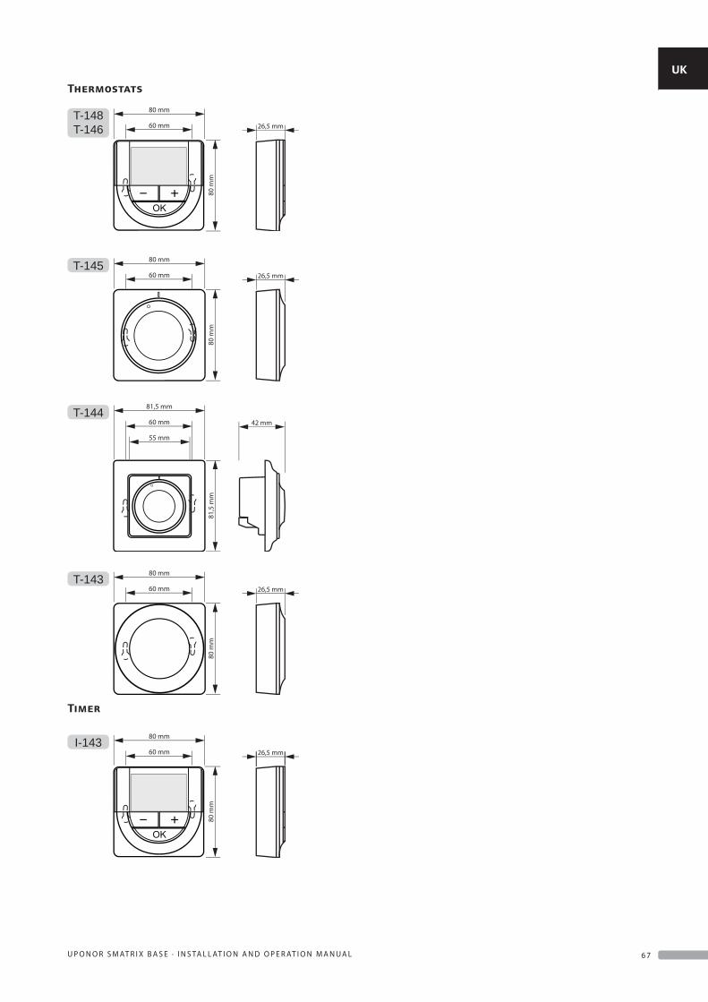
Thermostats
T-148T-146
80 m
m
60 mm
80 mm
26,5 mm
T-145
80 m
m
60 mm
80 mm
26,5 mm
T-144
81,5
mm
60 mm
55 mm
81,5 mm
42 mm
T-143
80 m
m
60 mm
80 mm
26,5 mm
Timer
I-143
80 m
m
60 mm
80 mm
26,5 mm
UK
CZ
DE
DK
EE
ES
FI
FR
HR
HU
IT
LT
LV
NL
NO
PL
PT
RO
RU
SE
SK
6 7U P O N O R S M AT R I X B A S E · I N S TA L L AT I O N A N D O P E R AT I O N M A N U A L
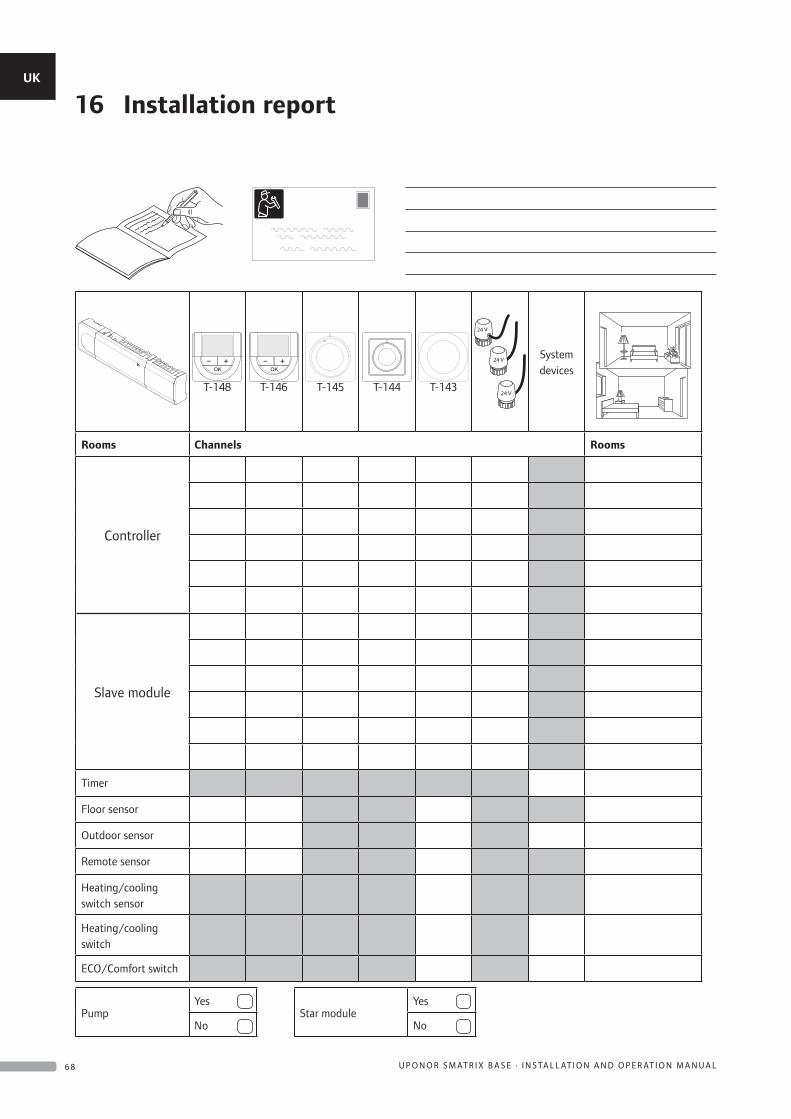
16 Installation report
T-148 T-146 T-145 T-144 T-143
24 V
24 V
24 V
System devices
Rooms Channels Rooms
Controller
Slave module
Timer
Floor sensor
Outdoor sensor
Remote sensor
Heating/cooling switch sensor
Heating/cooling switch
ECO/Comfort switch
PumpYes
Star moduleYes
No No
UK
CZ
DE
DK
EE
ES
FI
FR
HR
HU
IT
LT
LV
NL
NO
PL
PT
RO
RU
SE
SK
6 8 U P O N O R S M AT R I X B A S E · I N S TA L L AT I O N A N D O P E R AT I O N M A N U A L
UK
CZ
DE
DK
EE
ES
FI
FR
HR
HU
IT
LT
LV
NL
NO
PL
PT
RO
RU
SE
SK
6 9U P O N O R S M AT R I X B A S E · I N S TA L L AT I O N A N D O P E R AT I O N M A N U A L

1068
124
03_
2015
_UK
Prod
uctio
n: U
pono
r AB
; Virs
bo, S
wed
en
Uponor Ltdwww.uponor.co.uk
Uponor reserves the right to make changes, without prior notification, to the specification of incorporated components in line with its policy of continuous improvement and development.