Embed Size (px)
Citation preview
Gebrauchsanleitung
99.821.70 3.5/01/12
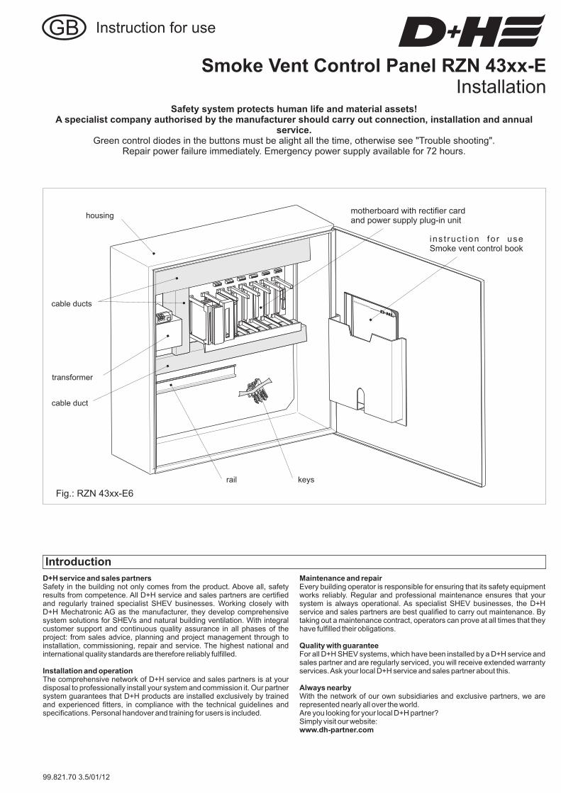
housing
transformer
rail
cable duct
cable ducts
motherboard with rectifier cardand power supply plug-in unit
keys
Smoke Vent Control Panel RZN 43xx-EInstallation
Safety system protects human life and material assets!A specialist company authorised by the manufacturer should carry out connection, installation and annual
service.Green control diodes in the buttons must be alight all the time, otherwise see "Trouble shooting".
Repair power failure immediately. Emergency power supply available for 72 hours.
Instruction for use
ins t ruc t ion fo r useSmoke vent control book
Fig.: RZN 43xx-E6
D+H service and sales partners
Installation and operation
Safety in the building not only comes from the product. Above all, safetyresults from competence. All D+H service and sales partners are certifiedand regularly trained specialist SHEV businesses. Working closely withD+H Mechatronic AG as the manufacturer, they develop comprehensivesystem solutions for SHEVs and natural building ventilation. With integralcustomer support and continuous quality assurance in all phases of theproject: from sales advice, planning and project management through toinstallation, commissioning, repair and service. The highest national andinternational quality standards are therefore reliably fulfilled.
The comprehensive network of D+H service and sales partners is at yourdisposal to professionally install your system and commission it. Our partnersystem guarantees that D+H products are installed exclusively by trainedand experienced fitters, in compliance with the technical guidelines andspecifications. Personal handover and training for users is included.
Maintenance and repair
Quality with guarantee
Always nearby
www.dh-partner.com
Every building operator is responsible for ensuring that its safety equipmentworks reliably. Regular and professional maintenance ensures that yoursystem is always operational. As specialist SHEV businesses, the D+Hservice and sales partners are best qualified to carry out maintenance. Bytaking out a maintenance contract, operators can prove at all times that theyhave fulfilled their obligations.
For all D+H SHEV systems, which have been installed by a D+H service andsales partner and are regularly serviced, you will receive extended warrantyservices.Ask your local D+H service and sales partner about this.
With the network of our own subsidiaries and exclusive partners, we arerepresented nearly all over the world.Are you looking for your local D+H partner?Simply visit our website:
Introduction
min
152
45 30
sec
202
60 40
OK
AUTO
M
2/16 RZN 43xx-E 99.821.70 3.5/01/12
Weather automatic switched on
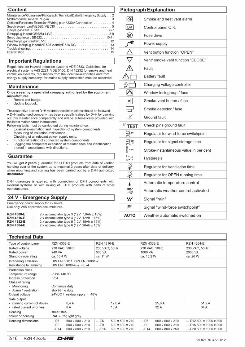
Technical Data
Type of control panel RZN 4308-E RZN 4316-E RZN 4332-E RZN 4364-E
Protection class I
Ingress protection IP54Class of rating- Monitoring Continous duty- Alarm / ventilation short-time dutyOutput voltage 24VDC / residual ripple 48%
Safe output- running current of drives- rated current of drives
Housing sheet steelcolour of housing RAL 7035; light grey
Rated voltage 230 VAC, 50Hz 230 VAC, 50Hz 230 VAC, 50Hz 230 VAC, 50HzRated power 240 VA 500 VA 1000 VA 2000 VAStand-by operating ca. 10,4 W ca. 11 W ca. 16,2 W ca. 26 W
Interfering emission DIN EN 55011; DIN EN 50081-2Resistance to jamming DIN EN 61000-4 -2, -3, -4
Temperature range -5 bis +40 °C
6,4 A 12,8 A 25,6 A 51,2 A8 A 16 A 32 A 64 A
Housing dimensions ...-E6 500 x 500 x 210 ...-E6 500 x 500 x 210 ...-E6 600 x 600 x 210 ...-E12 800 x 1000 x 300...-E9 600 x 600 x 210 ...-E9 600 x 600 x 210 ...-E9 600 x 600 x 210 ...-E15 800 x 1000 x 300...-E14 600 x 600 x 210 ...-E14 600 x 600 x 210 ...-E14 600 x 800 x 250 ...-E20 800 x 1000 x 300
≈
Automatic temperature control
Signal "rain"
Signal "wind-force switchpoint"
Guarantee
You will get guarantee for all D+H products from date of verifiedhanding over of the system up to maximal 3 years after date of delivery,when mounting and starting has been carried out by a D+H authorized
.
D+H guarantee is expired, with connection of D+H components withexternal systems or with mixing of D+H products with parts of othermanufacturers.
2 years
distributor
MaintenanceOnce a year by a specialist company authorised by the equipmentmanufacturer.- Renew test badge.- Update logbook.
The respective current D+H maintenance instructions should be followed.A D+H authorised company has been specially trained by D+H for carryingout this maintenance competently and will be automatically provided withthe latest maintenance instructions.Following tests must be carried out during maintenance:- External examination and inspection of system components- Measuring of insulation resistances- Checking of all relevant power supply units.- Functional testing of connected system components.- Logging the competent execution of maintenance and identification
thereof in accordance with directions.
Important RegulationsRegulations for Hazard detection systems VDE 0833, Guidelines forelectrical systems VdS 2221, VDE 0100, DIN 18232 for smoke and heatventilation systems, regulations from the local fire-authorities and fromenergy supply company, for mains supply connection must be observed.
Pictograph Explanation
Smoke and heat vent alarm
Control panel O.K.
Fuse drive
Power supply
Vent button function “OPEN”
Vent/ smoke vent function “CLOSE”
Fault
Battery fault
Charging voltage controller
Check pins ground fault
Regulator for wind-force switchpoint
Regulator for signal storage time
Ground fault
Smoke detector / fuse
Smoke-vent button / fuse
Window-lock group / fuse
Stroke-instantaneous value in per cent
Hysteresis
Regulator for Ventilation time
Regulator for OPEN running time
Automatic weather control activated
24 V - Emergency SupplyEmergency power supply for 72 hours.Use only VdS approved accumulators.
: 2 x accumulator type 3 (12V, 7,0Ah ± 15%): 2 x accumulator type 4 (12V, 12Ah ± 15%): 2 x accumulator type 5 (12V, 18Ah ± 15%): 2 x accumulator type 6 (12V, 26Ah ± 15%)
RZN 4308-ERZN 4316-ERZN 4332-ERZN 4364-E
ContentMaintenance/Guarantee/Pictograph/TechnicalData/EmergencySupply . . . 2Motherboard/General Plug-in . . . . . . . . . . . . . . . . . . . . . . . . . . . . . . . . . . 3OptionalFunctionalExtension/Wiring plan / 230V Connection . . . . . . . . . . 4Supplyplug-incardVE520/VE530 . . . . . . . . . . . . . . . . . . . . . . . . . . . . . . . 5Lineplug-incardLE513 . . . . . . . . . . . . . . . . . . . . . . . . . . . . . . . . . . . . . . 6-7Groupplug-incardGE628(-L)V2 . . . . . . . . . . . . . . . . . . . . . . . . . . . . . . . 8-9Servoplug-incardSE622. . . . . . . . . . . . . . . . . . . . . . . . . . . . . . . . . . . 10-11Weatherplug-incardWE516. . . . . . . . . . . . . . . . . . . . . . . . . . . . . . . . . . . 12Window-lockplug-incardAE525-AandAE526-DG. . . . . . . . . . . . . . . . . . . 13Troubleshooting. . . . . . . . . . . . . . . . . . . . . . . . . . . . . . . . . . . . . . . . . . . . 14Examination. . . . . . . . . . . . . . . . . . . . . . . . . . . . . . . . . . . . . . . . . . . . . . . 15
OK
RZN 43xx-E 3/1699.821.70 3.5/01/12
GKS567
566
NBE
N+
24V=
VE530
ServiceUSB/PC
F3,15A
F1,25A
F0,125A
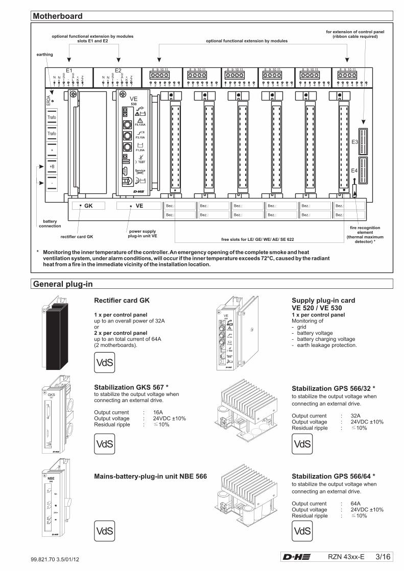
Motherboard
1 2 3 4 5 6 7
N-
N+
SSt -
SAL
+K
ZZ
E1
1 2 3 4 5 6 7
N-
N+
SSt -
SAL
+K
ZZ
E2
1 2 3 4 5 6 7 1 2 3 4 5 6 7 1 2 3 4 5 6 7 1 2 3 4 5 6 7 1 2 3 4 5 6 7 1 2 3 4 5 6 7
8 9 10 11 8 9 10 11 8 9 10 11 8 9 10 11 8 9 10 11 8 9 10 11
Bez.:
Bez.:
Bez.:
Bez.:
Bez.:
Bez.:
Bez.:
Bez.:
Bez.:
Bez.:
Bez.:
Bez.:
GK VE
Trafo
Trafo
+
+B
-
ERD
A
E3
E4
optional functional extension by modulesslots E1 and E2
earthing
optional functional extension by modules
for extension of control panel(ribbon cable required)
fire recognitionelement
(thermal maximumdetector) *
free slots for LE/ GE/ WE/ AE/ SE 622
batteryconnection
rectifier card GK
power supplyplug-in unit VE
* Monitoring the inner temperature of the controller.An emergency opening of the complete smoke and heatventilation system, under alarm conditions, will occur if the inner temperature exceeds 72°C, caused by the radiantheat from a fire in the immediate vicinity of the installation location.
VE530
ServiceUSB/PC
F3,15A
F1,25A
F0,125A
Rectifier card GK
1 x per control panel
2 x per control panel
up to an overall power of 32Aor
up to an total current of 64A(2 motherboards).
Supply plug-in cardVE 520 / VE 5301 x per control panelMonitoring of- grid- battery voltage- battery charging voltage- earth leakage protection.
Stabilization GKS 567 *to stabilize the output voltage whenconnecting an external drive.
Output current : 16AOutput voltage : 24VDC ±10%Residual ripple : 10%≤
Mains-battery-plug-in unit NBE 566
Stabilization GPS 566/32 *to stabilize the output voltage when
connecting an external drive.
Output current : 32AOutput voltage : 24VDC ±10%Residual ripple : 10%≤
Stabilization GPS 566/64 *to stabilize the output voltage when
connecting an external drive.
Output current : 64AOutput voltage : 24VDC ±10%Residual ripple : 10%≤
General plug-in
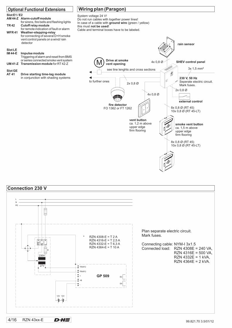
* RZN 4308-E = T 2 ARZN 4316-E = T 2,5 ARZN 4332-E = T 6,3 ARZN 4364-E = T 10 A
*
4/16 RZN 43xx-E 99.821.70 3.5/01/12
230 V, 50 HzSeperate electric circuit.Mark fuses.
to further ones
see line lenghts and cross sections
Drive at smokevent opening
SHEV control panel
vent buttonca. 1,2 m aboveupper edgefirm flooring
smoke vent buttonca. 1,5 m aboveupper edgefirm flooring
external controlfire detector
FO 1362 or FT 1262
4x 0,8 Ø
8x 0,8 Ø (RT 45)10x 0,8 Ø (RT 45-LT)
8x 0,8 Ø (RT 45)10x 0,8 Ø (RT 45-LT)
2x 0,8 Ø
2x 0,8 Ø
OK
OK
rain sensor
4x 0,8 Ø
3x 1,5 mm²
Wiring plan (Paragon)
System voltage 24 V!Do not run cables with together power lines!In case of a cable with (green / yellow)this must !Cable and terminal boxes have to be labeled.
ground wirenot be used
Slot E1 / E2AM 44-Z Alarm-cutoff module
TR 42 Cutoff relay module
WFR 41 Weather-stepping-relay
Slot LEIM 44-E Impulse module
UM 41-Z Transmission module
for sirens, fire bells and flashing lights
for remote indication of fault or alarm
for connecting of several D+H smokevent control panels on a wind/ raindetector
Triggering ofalarmand reset fromBMSorseriesconnected smoke vent system
for RT 42-Z
Slot GEAT 41 Drive starting time-lag module
in conjunction with shading systems
Optional Functional Extensions
Connection 230 V
Plan separate electric circuit.Mark fuses.
Connecting cable: NYM-I 3x1.5Connected load: RZN 4308E = 240 VA,
RZN 4316E = 500 VA,RZN 4332E = 1 kVA,RZN 4364E = 2 kVA.
RZN 43xx-E 5/1699.821.70 3.5/01/12
VE530
ServiceUSB/PC
F3,15A
F1,25A
F0,125A
1 2 3 4 5 6
X5
1 2
RM RT
LE
3 4 5 6 7 8
-
RT 45
RT
45
10k�
-
n.c
.
2 7 58 3 1 6 4
n.c
.-
2 3 1 6 4
8
7 5
X5 / VE
1 2 3 4 5 6
LTO
ut
1
LTIn
1
LTO
ut
2
LTIn
2
LT 43 (-SD)
–N
–N
5 6 71 2 3 4
LT MOT
L P
GE
LT4
3
L P
X5 / VE
1 2 3 4 5 6
LTO
ut
1
LTIn
1
LTO
ut
2
LTIn
2
ala
rm
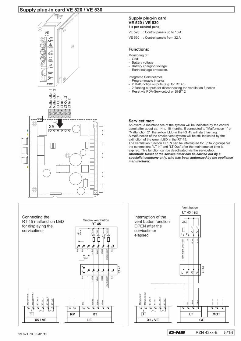
Supply plug-in card VE 520 / VE 530
Servicetimer:An overdue maintenance of the system will be indicated by the controlpanel after about ca. 14 to 16 months. If connected to "Malfunction 1" or"Malfunction 2" the yellow LED in the RT 45 will start flashing.A malfunction of the smoke vent system will be still indicated by theextinction of the green LED in the RT 45.The ventilation function OPEN can be interrupted for up to 2 groups viathe connections "LT In" and "LT Out" after the maintenance time isexpired. This function can be deactivated via the servicetool.Attention: Reset of the service timer can be carried out by aspecialist company only, who has been authorized by the appliancemanufacturer.
close
red
gree
n
yello
w
line
con
tro
l
clo
se
contr
ol
line
line
malfu
nct
ion
close
malfu
nct
ion
line
contr
ol
close
Ma
lfun
ctio
n1
Ma
lfun
ctio
n2
Smoke vent buttonConnecting theRT 45 malfunction LEDfor displaying theservicetimer
clo
se
op
en
clo
se
op
en
op
en
sig
na
l (o
nly
-SD
)
Ma
lfun
ctio
n1
Ma
lfun
ctio
n2
Vent button
Interruption of thevent button functionOPEN after theservicetimerelapsed
Supply plug-in cardVE 520 / VE 5301 x per control panel
VE 520 : Control panels up to 16 A
VE 530 : 32 AControl panels from
Monitoring of- Grid- Battery voltage- Battery charging voltage- Earth leakage protection.
Integrated Servicetimer- Programmable interval- 2 Malfunction outputs (e.g. for RT 45)- 2 floating outputs for disconnecting the ventilation function- Reset via PDA-Servicetool or BI-BT 2
Functions:M
alfu
nct
ion
1M
alfu
nct
ion
2LT
Out1
LTIn
1LT
Out2
LTIn
2
ala
rmala
rmala
rm
12
34
5
ON
513
LE
0I
F1,25A
TEST
F0,125A
F0,125A
6/16 RZN 43xx-E 99.821.70 3.5/01/12
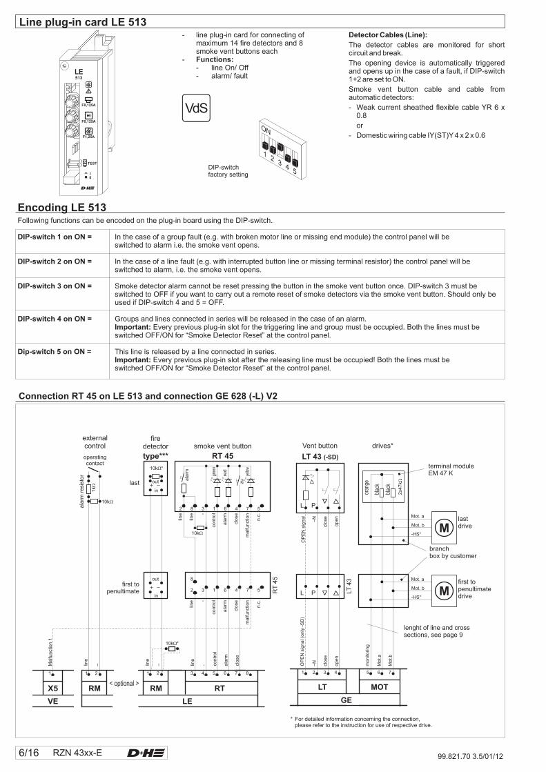
Detector Cables (Line):
The detector cables are monitored for shortcircuit and break.
The opening device is automatically triggeredand opens up in the case of a fault, if DIP-switch1+2 are set to ON.
Smoke vent button cable and cable fromautomatic detectors:
- Weak current sheathed flexible cable YR 6 x0.8
or
- Domestic wiring cable IY(ST)Y 4 x 2 x 0.6
Encoding LE 513Following functions can be encoded on the plug-in board using the DIP-switch.
In the case of a group fault (e.g. with broken motor line or missing end module) the control panel will beswitched to alarm i.e. the smoke vent opens.
In the case of a line fault (e.g. with interrupted button line or missing terminal resistor) the control panel will beswitched to alarm, i.e. the smoke vent opens.
Smoke detector alarm cannot be reset pressing the button in the smoke vent button once. DIP-switch 3 must beswitched to OFF if you want to carry out a remote reset of smoke detectors via the smoke vent button. Should only beused if DIP-switch 4 and 5 = OFF.
Groups and lines connected in series will be released in the case of an alarm.Every previous plug-in slot for the triggering line and group must be occupied. Both the lines must be
switched OFF/ON for “Smoke Detector Reset” at the control panel.
This line is released by a line connected in series.Every previous plug-in slot after the releasing line must be occupied! Both the lines must be
switched OFF/ON for “Smoke Detector Reset” at the control panel.
DIP-switch 1 on ON =
DIP- 4 on ON =
Dip- 5 on ON =
DIP-switch 2 on ON =
DIP-switch 3 on ON =
switchImportant:
switchImportant:
- line plug-in card for connecting ofmaximum 14 fire detectors and 8smoke vent buttons each
-- line On/ Off- alarm/ fault
Functions:
DIP-switchfactory setting
Connection RT 45 on LE 513 and connection GE 628 (-L) V2
11 22
RM RM RT
LE
31 4 5 6 7 8
X5
externalcontrol
firedetector
type***operatingcontact
ala
rmre
sist
or
10k *�
10k�
1k�
out
out
in
in
last
first topenultimate
line
line
– – line
Ma
lfun
ctio
n1
- con
tro
l
ala
rm
clo
se
smoke vent button
RT 45
RT
45
10k�
ala
rm
con
tro
l-
line
line
ma
lfun
ctio
n
n.c
.
clo
se
2 7 58 3 1 6 4
ala
rm
zu
red
gree
n
yello
wm
alfu
nct
ion
n.c
.
line -
con
tro
l
ala
rm
clo
se
2 3 1 6 4
8
7 5
10k *�
< optional >
Line plug-in card LE 513
Vent button drives*
LT 43 (-SD)
EM 47 Kterminal module
lenght of line and crosssections, see page 9
clo
se–N
OP
EN
sig
na
l
op
en
clo
se
OP
EN
sig
na
l (o
nly
-SD
)
–N
op
en
mo
nito
rin
g
Mo
t.a
Mo
t.b
5 6 71 2 3 4
LT MOT
L P
GE
blac
k
blac
k
oran
ge
2x4
7k�
branchbox by customer
first topenultimatedrive
LT4
3
L PMot. b
-HS*
Mot. a
* For detailed information concerning the connection,please refer to the instruction for use of respective drive.
lastdriveMot. b
-HS*
Mot. a
VE
RZN 43xx-E 7/1699.821.70 3.5/01/12
1 2 3 4 5 6 7 8 1
RM
LE
RT X5
line
line
–– contr
ol
ala
rm
close
Smoke vent button1st line
Smoke vent button2nd line
RT 45 RT 45
RT
45
RT
45
10k�
10k�
ala
rm
ala
rm
contr
ol
contr
ol- -
line
line
line
line
malfu
nct
ion
n.c
.
malfu
nct
ion
n.c
.
close
close
2 27 5 7 58 83 31 16 64 4
ala
rm
ala
rm
close
close
red
red
gree
n
gree
n
yello
w
yello
w
mal
func
tion
n.c.
malfu
nct
ion
n.c
.
line
line- -
contr
ol
contr
ol
ala
rm
ala
rm
close
close
2 23 31 16 64 4
8 8
7 5 7 5
last smokevent button
each
first topenultimatesmoke ventbutton each
Malfu
nc-
tion
1
shunt connectionby customer
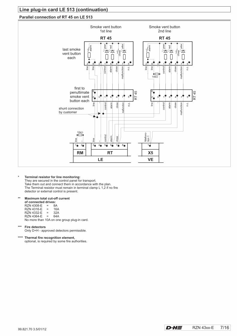
Line plug-in card LE 513 (continuation)
Parallel connection of RT 45 on LE 513
* Terminal resistor for line monitoring:
** Maximum total cut-off currentof connected drives:
*** Fire detectors
**** Thermal fire recognition element,
They are secured in the control panel for transport.Take them out and connect them in accordance with the plan.The must remain in terminal clamp L 1,2 if no firedetector or external control is present.
RZN 4308-E = 8ARZN 4316-E = 16ARZN 4332-E = 32ARZN 4364-E = 64ANo more than 10A on one group plug-in card.
Only D+H - approved detectors permissible.
optional, is required by some fire authorities.
Terminal resistor
VE
min
152
45 30
sec
202
60 40
628 V2GE
MF8,0A
min
152
45 30
sec
202
60 40
12
34
56
78
9 10
ON
8/16 RZN 43xx-E
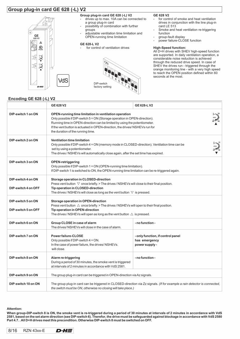
Encoding GE 628 (-L) V2
Attention:
When group-DIP-switch 8 is ON, the smoke vent is re-triggered during a period of 30 minutes at intervals of 2 minutes in accordance with VdS2581, based on the set alarm direction (see DIP-switch 6). Therefor, the drive must be safeguarded against blockage in accordance with VdS 2580Part 4.7. .All D+H drives meet this precondition. Otherwise DIP-switch 8 must be switched on OFF.
Group plug-in card GE 628 (-L) V2
GE 628-L V2
- drives up to max. 10A can be connected toa group plug-in card
- possibility of combination with furthergroups
- adjustable ventilation time limitation andOPEN-running time limitation
- for control of ventilation drives
DIP-switchfactory setting
Group plug-in card GE 628 (-L) V2
Only possible if DIP-switch 4 = ON (memory mode in CLOSED-direction). Ventilation time can be
set by using a potentiometer.
The drives / NSHEVs will automatically close again, after the set time has expired.
Only possible if DIP-switch 1 = ON (OPEN-running time limitation).
If DIP-switch 1 is switched to ON, the OPEN-running time limitation can be re-triggered again.
Press vent button once briefly. > The drives / NSHEVs will close to their final position.
The drives / NSHEVs will close as long as the vent button is pressed.
Press vent button once briefly. > The drives / NSHEVs will open to their final position.
The drives / NSHEVs will open as long as the vent button is pressed.
The drives/ NSHEVs will close in the case of alarm.
Only possible if DIP-switch 4 = ON.
In the case of power failure, the drives/ NSHEVs.
.
During a period of 30 minutes, the smoke vent is triggered
at intervals of 2 minutes in accordance with VdS 2581.
The group plug-in card can be triggered in OPEN-direction viaAz signals.
The group plug-in card can be triggered in CLOSED-direction via Zz signals.
GE 628 V2 GE 628-L V2
DIP-switch 1 on ON OPEN-running time limitation in ventilation operation
DIP-switch 2 on ON Ventilation time limitation
DIP-switch 3 on ON OPEN-retriggering
DIP-switch 4 on ON Storage operation in CLOSED-direction
DIP-switch 4 on OFF Tip operation in CLOSED-direction
DIP-switch 5 on ON Storage operation in OPEN-direction
DIP-switch 5 on OFF Tip operation in OPEN-direction
DIP-switch 6 on ON Group CLOSE in case of alarm - no function -
DIP-switch 7 on ON Power failure-CLOSE - only function, if control panel
has emergency
power supply -
DIP-switch 8 on ON Alarm re-triggering - no function -
DIP-switch 9 on ON
DIP-switch 10 on ON
If the vent button is actuated in OPEN-direction, the drives/ NSHEVs run for
the duration of the running time.
will close
(If for example a rain detector is connected,
the switch must be ON, otherwise no closing will take place.)
Only possible if DIP-switch 5 = ON (Storage operation in OPEN-direction).
Running time in OPEN-direction can be limited by using the potentiometer.
GE 628 V2
High-Speed function:
- for control of smoke and heat ventilationdrives in conjunction with the line plug-incard LE 513
- Smoke and heat ventilation re-triggeringfunction
- group-fault display- power failure-CLOSE function
All D+H drives with SHEV high-speed functionare supported. In daily ventilation operation, aconsiderable noise reduction is achievedthrough the reduced drive speed. In case ofSHEV the drives run - triggered through theorange monitoring line - with a very high speedto reach the OPEN position defined within 60seconds at the most.
RZN 43xx-E 9/16
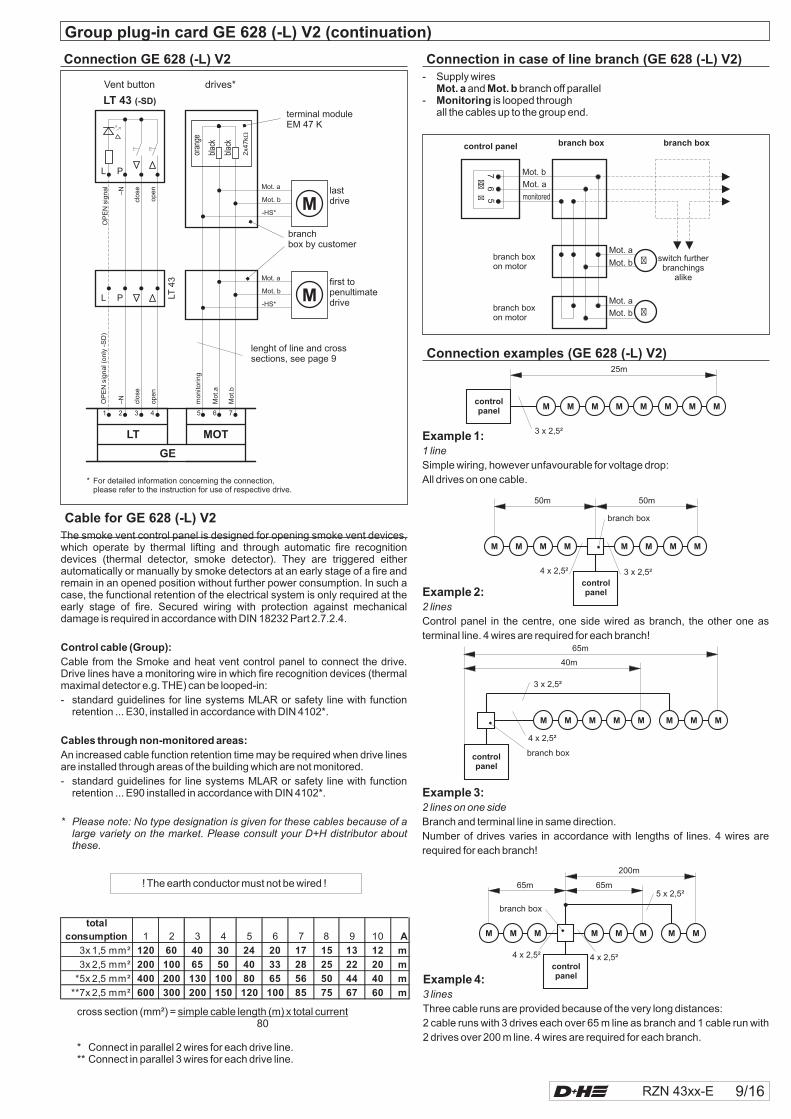
Connection GE 628 (-L) V2
- Supply wiresand branch off parallel
- is looped throughall the cables up to the group end.
Mot. a Mot. bMonitoring
Connection in case of line branch (GE 628 (-L) V2)
The smoke vent control panel is designed for opening smoke vent devices,which operate by thermal lifting and through automatic fire recognitiondevices (thermal detector, smoke detector). They are triggered eitherautomatically or manually by smoke detectors at an early stage of a fire andremain in an opened position without further power consumption. In such acase, the functional retention of the electrical system is only required at theearly stage of fire. Secured wiring with protection against mechanicaldamage is required in accordance with DIN 18232 Part 2.7.2.4.
Cable from the Smoke and heat vent control panel to connect the drive.Drive lines have a monitoring wire in which fire recognition devices (thermalmaximal detector e.g. THE) can be looped-in:
- standard guidelines for line systems MLAR or safety line with functionretention ... E30, installed in accordance with DIN 4102*.
An increased cable function retention time may be required when drive linesare installed through areas of the building which are not monitored.
- standard guidelines for line systems MLAR or safety line with functionretention ... E90 installed in accordance with DIN 4102*.
Control cable (Group):
Cables through non-monitored areas:
* Please note: No type designation is given for these cables because of alarge variety on the market. Please consult your D+H distributor aboutthese.
! The earth conductor must not be wired !
cross section (mm²) =80
* Connect in parallel 2 wires for each drive line.** Connect in parallel 3 wires for each drive line.
simple cable length (m) x total current
total
consumption 1 2 3 4 5 6 7 8 9 10 A
3x 1,5 mm² 120 60 40 30 24 20 17 15 13 12 m
3x 2,5 mm² 200 100 65 50 40 33 28 25 22 20 m
*5x 2,5 mm² 400 200 130 100 80 65 56 50 44 40 m
**7x 2,5 mm² 600 300 200 150 120 100 85 75 67 60 m
Cable for GE 628 (-L) V2
Connection examples (GE 628 (-L) V2)
controlpanel
M
25m
3 x 2,5²
M M M M M M M
Example 1:
1 line
Simple wiring, however unfavourable for voltage drop:
All drives on one cable.
Example 2:
2 lines
Control panel in the centre, one side wired as branch, the other one as
terminal line. 4 wires are required for each branch!
Example 3:
2 lines on one side
Branch and terminal line in same direction.
Number of drives varies in accordance with lengths of lines. 4 wires are
required for each branch!
Example 4:
3 lines
Three cable runs are provided because of the very long distances:
2 cable runs with 3 drives each over 65 m line as branch and 1 cable run with
2 drives over 200 m line. 4 wires are required for each branch.
Group plug-in card GE 628 (-L) V2 ( )continuation
M
50m
3 x 2,5²4 x 2,5²
branch box
50m
M M M M M M M
controlpanel
M
controlpanel
65m
40m
4 x 2,5²
3 x 2,5²
M M M M M M M
branch box
M
65m 65m
200m
4 x 2,5² 4 x 2,5²
5 x 2,5²
M M M M M MM
controlpanel
branch box
��
�
control panel
Mot. b76
5
Mot. a
monitored
�
�
Mot. a
Mot. b
Mot. a
Mot. b
branch boxon motor
branch boxbranch box
branch boxon motor
switch furtherbranchings
alike
Vent button drives*
LT 43 (-SD)
EM 47 Kterminal module
lenght of line and crosssections, see page 9
clo
se–N
OP
EN
sig
na
l
op
en
clo
se
OP
EN
sig
na
l (o
nly
-SD
)
–N
op
en
mo
nito
rin
g
Mo
t.a
Mo
t.b
5 6 71 2 3 4
LT MOT
L P
GE
blac
k
blac
k
oran
ge
2x4
7k�
branchbox by customer
first topenultimatedrive
LT4
3
L PMot. b
-HS*
Mot. a
* For detailed information concerning the connection,please refer to the instruction for use of respective drive.
lastdriveMot. b
-HS*
Mot. a
622
12
34
56
78
ON
10/16 RZN 43xx-E 99.821.70 3.5/01/12
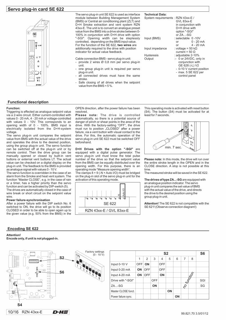
The servo plug-in unit SE 622 is used as interfacemodule between Building Management System(BMS) or Central air conditioning plant (ZLT) andD+H Smoke extraction and vent system RZN43xx-E. The unit is to convert an analogue presetvalue from the BMS into a drive stroke between 0-100% in conjunction with D+H drive with option"-SGI". Opening width can be steplesslycontrolled, depending on the BMS input value.For the function of the SE 622, areadditionally required to the drive with positionindicator for actual value feedback.
Cable connection BMS - servo plug-in unit:- provide 2 wires Ø 0,8 mm per servo plug-in
unit.- one group plug-in unit is required per servo
plug-in unit.- all connected drives must have the same
stroke.- Safe closing of all drives when the setpoint
value from the BMS < 5 %.
two wires
Servo plug-in card SE 622Technical Data:System requirements : RZN 43xx-E /
GVL 83xx-Ein conjunction withD+H drive withoption "-SGI"or ZA...-SG
Input (BMS) : selectable 0 -10Vor 0 - 20 mAor 4 - 20 mA
Input impedance : voltage = 50 kcurrent = 50
Hysteresis : adjustable 2-10%Output :- 0 or 24VDC, only in
conjunction withGE 628 (-L) V2
- 0-10 V current position- max. 5 SE 622 per
control panel
ΩΩ
Functional description
Factory settings(0 - 10 V)
SG
SG
I
ON
12345678 12345678
Function:
Power failure-synchronisation
Triggering is effected as analogue setpoint valuevia a 2-wire circuit. Either current-controlled withvalues 0 - 20 mA, 4 - 20 mA or voltage-controlledwith values 0 - 10V. This corresponds to anopening width of 0 - 100%. BMS input iselectrically isolated from the D+H-systemvoltage.The servo plug-in unit compares the setpointvalue from BMS with the actual value of the driveand operates the drive to the desired position,using the group plug-in unit. The servo functioncan be switched off at the plug-in unit or byremote control. Then the drive group can bemanually opened or closed by built-in ventbuttons or external vent buttons LT. The actualvalue can be checked on a digital display on theplug-in unit. The feedback to the BMS is providedas analogue signal with values 0 - 10 V.The servo function is overridden in the case of analarm from the Smoke and heat vent system. Thefunction “Master CLOSE“, e.g. in the case of rainor a timer, has a higher priority than the servofunction and can be activated by DIP-switch (5).The drives are automatically closed in the case ofwire break or short circuit on the setpoint valuewire.
After a power failure with the DIP switch No. 6switched to ON, the drive will go to its positionCLOSED in order to be able to open again up tothe given value (e.g. 50% from the BMS) in the
Attention!Encode only, if unit is not plugged-in.
OPEN direction, after the power failure has beenresolved.
The drive is controlledautomatically, so there is a potential source ofdanger of pinch or shear points in the area of thedrive. With the factory-setting “OFF“, the drivemust run to position „CLOSED“ after a powerfailure, via a vent button with visual contact to thedrive. For this, the automatic operation of theservo plug-in unit SE 622 must be switched OFFbeforehand.
areequipped with a digital pulse generator. Theservo plug-in unit must know the total pulsenumber of the drive so that the setpoint valuefrom the BMS can be equally distributed over theopening width. For this purpose, there is anoperating mode “Measure opening width“.The clamps 8 + 9 (-N + Auto I/O) must be bridgedon the plug-in slot of the servo plug-in unit for theactivation of this operating mode.
Please note:
D+H Drives with the option "-SGI"
This operating mode is activated with reset button(S4). The button (S4) must be activated for atleast for 7 seconds.
Auto
I/O
-N
SE 622
RZN 43xx-E / GVL 83xx-E
10 11 3 4 5 76 8 9
0
min. 7 sec.
Please note:
The drives of type ZA...-SG
Attention!
In this mode, the drive will run overthe entire stroke length in the OPEN and in theCLOSE direction. A stop is not possible at thistime.The measured stroke will be saved in the SE 622.
are equipped withan analogue position indicator. The servoplug-in unit compares the set value of BMSwith the actual value of the drive, and directsthe drive to the desired position using thegroup plug-in unit.
The SE 622 is not compatible with theSE 621! (Observe connection diagram!)
Encoding SE 622
S2
S6
S4
Master CLOSE funct.
ZA...-SG
Drive with "-SGI"
Input 4-20 mA
Input 0-20 mA
Input 0-10 V
1
OFF
ON
ON
ON
ON
ON
2
ON
OFF
OFF
OFF
3 4 5 6 7 8
Power failure sync.
OFF
OFF
ON
S2 S6
SGI
SGnofu
nctio
n
RZN 43xx-E 11/1699.821.70 3.5/01/12
Servo plug-in card SE 622 continuation( )
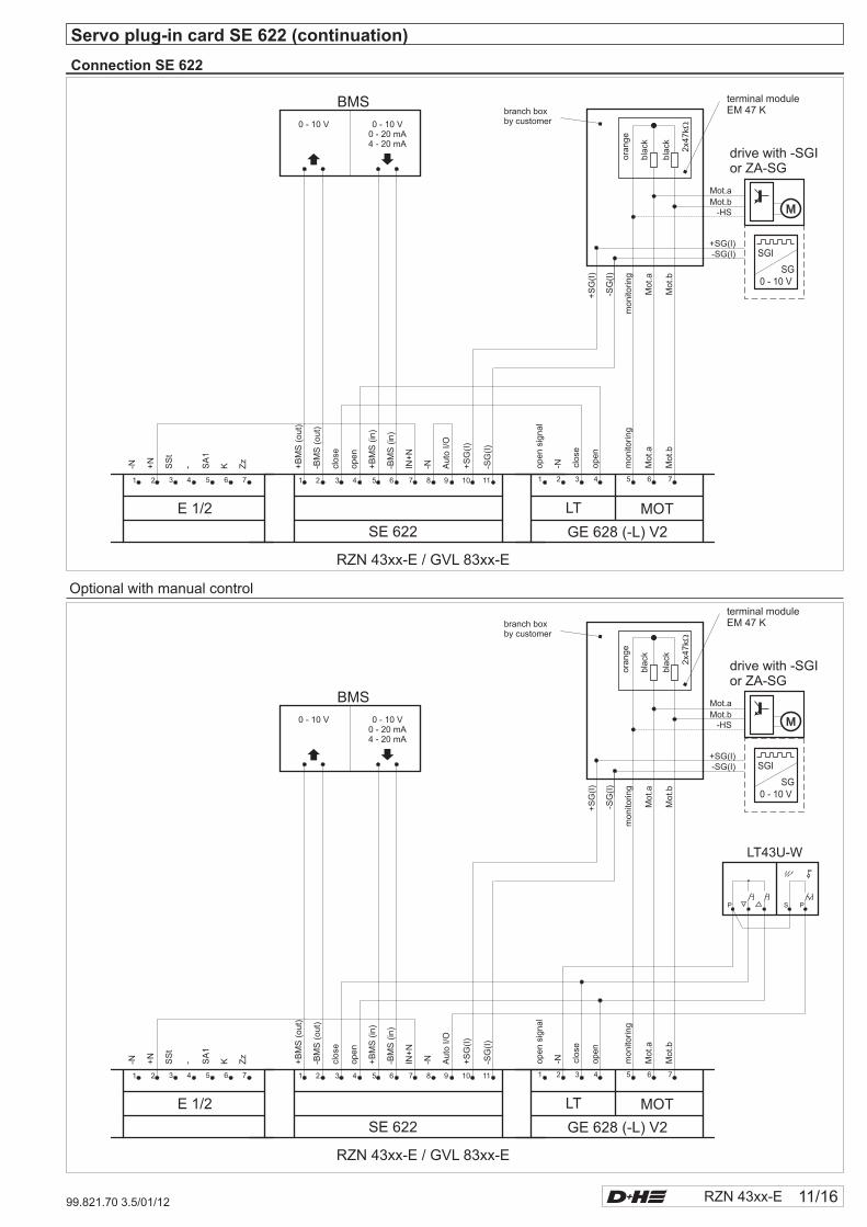
Connection SE 622
Optional with manual control
SG
SG
I
ON
12345678
LT43U-W
P PS
0 - 10 V0 - 20 mA4 - 20 mA
BMS
Mot.
b
Mot.
a
monito
ring
open
close
-Nopen
signal
Auto
I/O
+S
G(I
)
-SG
(I)
-NIN+
N
-BM
S(in)
+B
MS
(in)
open
-BM
S(o
ut)
close
+B
MS
(out)
Zz
KSA
1
-SS
t
+N
-N
1
GE 628 (-L) V2SE 622
RZN 43xx-E / GVL 83xx-E
E 1/2
2 3 4 5 6 71 2 3 314 425 56 7 76 8 9 10 11
+S
G(I
)
monito
ring
Mot.
a
Mot.
b
drive with -SGIor ZA-SG
-SG
(I)
bla
ck
bla
ck
ora
nge
2x4
7k�
branch boxby customer
terminal moduleEM 47 K
LT MOT
Mot.aMot.b
-HS
-SG(I)+SG(I)
SGI
0 - 10 V
0 - 10 VSG
0 - 10 V0 - 20 mA4 - 20 mA
BMS
Mot.b
Mot.a
monito
ring
open
close
-Nopen
signal
Auto
I/O
+S
G(I
)
-SG
(I)
-NIN+
N
-BM
S(in)
+B
MS
(in)
open
-BM
S(o
ut)
close
+B
MS
(out)
Zz
KSA
1
-SS
t
+N
-N
1
GE 628 (-L) V2SE 622
RZN 43xx-E / GVL 83xx-E
E 1/2
2 3 4 5 6 71 2 3 314 425 56 7 76 8 9 10 11
+S
G(I
)
monito
ring
Mot.a
Mot.b
drive with -SGIor ZA-SG
-SG
(I)
bla
ck
bla
ck
ora
nge
2x4
7k�
branch boxby customer
terminal moduleEM 47 K
LT MOT
Mot.aMot.b
-HS
-SG(I)+SG(I)
SGI
0 - 10 V
0 - 10 VSG
F0.125A
F0.125A
F1.25A
F6.3A
TEST
516
12/16 RZN 43xx-E 99.821.70 3.5/01/12
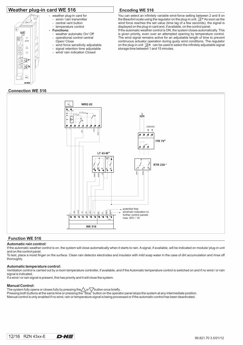
- weather plug-in card for- wind-/ rain transmitter- central vent button- temperature control
- weather automatic On/ Off- operational control central
Open/ Close- wind force sensitivity adjustable- signal retention time adjustable- wind/ rain indication Closed
- Functions:
You can select an infinitely variable wind-force setting between 2 and 8 onthe Beaufort scale using the regulator on the plug-in unit. As soon as thewind force reaches the set value (time lag of a few seconds), the signal isdisplayed on the plug-in card and, if available, on the control panel.If the automatic weather control is ON, the system closes automatically. Thisis given priority, even over an attempted opening by temperature control.The wind signal remains active for an adjustable length of time to preventcontinuous actuator operation during gusty wind conditions. The regulatoron the plug-in unit can be used to select the infinitely adjustable signalstorage time between 1 and 15 minutes.
Encoding WE 516Weather plug-in card WE 516
Connection WE 516
LT 43-W
clo
se –N
op
en
P PS
ZZ
2
–N
ZM
P1
ZM
P2
1 2 3 4 5 6 7 8 9 10 11
WE 516
rain win
d
win
d
– +
1 2 4 3 5 7 6 8 9
R
W
WRG 82
S 1/1S 1/2
P3 P4
rain
+ win
d
–N
AZ
ZZ
1
–T
ITR 79
1
6
2
7
4
3 5
230VAC
51 3
RTR 230 *
op
en
clo
se
-
potential freewind/rain indication tofurther control panelsmax. 60V / 1A
Function WE 516
Automatic rain control:
Automatic temperature control:
Manual Control:
If the automatic weather control is on, the system will close automatically when it starts to rain. A signal, if available, will be indicated on module/ plug-in unitand on the control panel.To test, place a moist finger on the surface. Clean rain detector electrodes and insulator with mild soap water in the case of dirt accumulation and rinse offthoroughly.
Ventilation control is carried out by a room temperature controller, if available, and if the Automatic temperature control is switched on and if no wind / or rainsignal is indicated.If a wind / or rain signal is present, this has priority and it will close the system.
The system fully opens or closes fully by pressing the or button once briefly .Pressing both buttons at the same time or pressing the “Stop” button on the operator panel stops the system at any intermediate position.Manual control is only enabled if no wind, rain or temperature signal is being processed or if the automatic control has been deactivated.
12
ON
F0.125A
F0.125A
F1.25A
F6.3A
TEST
AE526-DG
12
ON
RZN 43xx-E 13/1699.821.70 3.5/01/12
AE525-A
0I
F6,3A
F1,25A
TEST
F0,125A
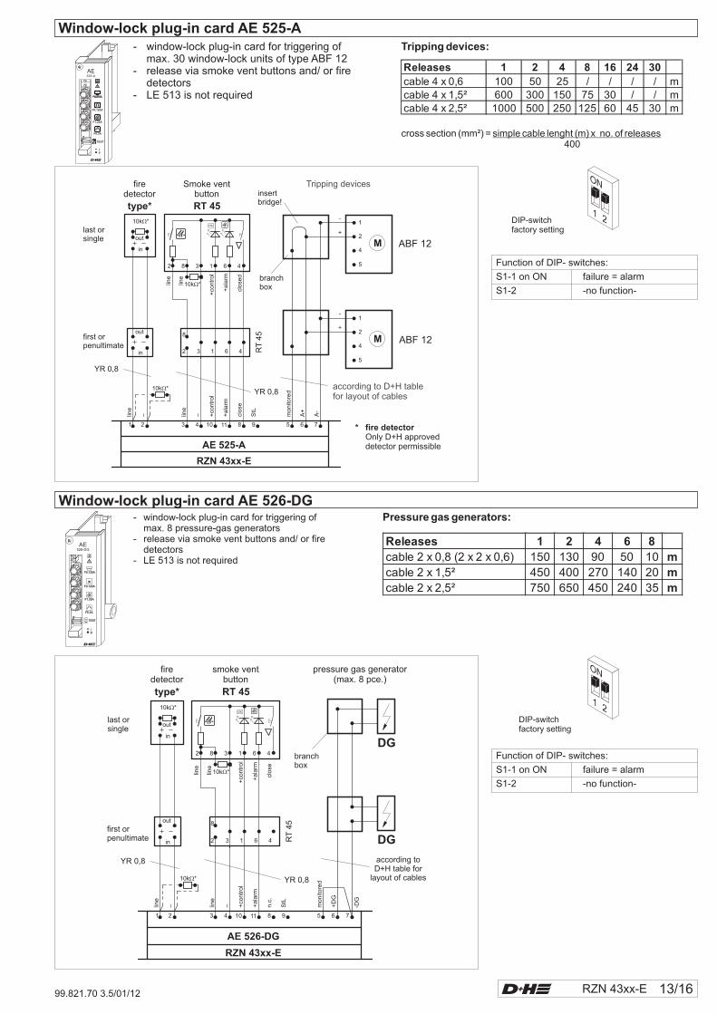
- window-lock plug-in card for triggering ofmax. 8 pressure-gas generators
- release via smoke vent buttons and/ or firedetectors
- LE 513 is not required
Releases 1 2 4 8 16 24 30
cable 4 x 0,6 100 50 25 / / / / mcable 4 x 1,5² 600 300 150 75 30 / / mcable 4 x 2,5² 1000 500 250 125 60 45 30 m
Releases 1 2 4 6 8
cable 2 x 0,8 (2 x 2 x 0,6) 150 130 90 50 10 m
cable 2 x 1,5² 450 400 270 140 20 m
cable 2 x 2,5² 750 650 450 240 35 m
Pressure gas generators:
cross section (mm²) =400
simple cable lenght (m) x no. of releases
Tripping devices:
Window-lock plug-in card AE 526-DG
- window-lock plug-in card for triggering ofmax. 30 window-lock units of type ABF 12
- release via smoke vent buttons and/ or firedetectors
- LE 513 is not required
Window-lock plug-in card AE 525-A
Function of DIP- switches:
S1-1 on ON failure = alarm
S1-2 -no function-
DIP-switchfactory setting
DIP-switchfactory setting
Function of DIP- switches:
S1-1 on ON failure = alarm
S1-2 -no function-
5 6 71 2 3 4 10 11 8 9
AE 525-A
RZN 43xx-E
firedetector
Smoke ventbutton
type* RT 45
10k *�
10k *�
10k *�
out
out
in
in
line
line
+co
ntr
ol
+a
larm
clo
sed
2
2
8
8
3
3
1
1
6
6
4
4
last orsingle
first orpenultimate
RT
45
line
line
– – +co
ntr
ol
+a
larm
clo
se
StL
A+
mo
nito
red
A-
OK
1
2
4
5
1
2
4
5
-
+
branchbox
M
M
ABF 12
ABF 12
-
+
Tripping devices
YR 0,8
YR 0,8according to D+H tablefor layout of cables
insertbridge!
* fire detectorOnly D+H approveddetector permissible
firedetector
smoke ventbutton
type* RT 45
10k *�
10k *�
10k *�
out
out
in
in
line
line
+co
ntr
ol
+ala
rm
close
2
2
8
8
3
3
1
1
6
6
4
4 RT
45
line
line
– – +co
ntr
ol
+ala
rm
n.c
.
StL
+D
G
monito
red
-DG
5 6 71 2 3 4 10 11 8 9
AE 526-DG
OK
branchbox
RZN 43xx-E
DG
DG
YR 0,8
YR 0,8
according toD+H table for
layout of cables
last orsingle
first orpenultimate
pressure gas generator(max. 8 pce.)
14/16 RZN 43xx-E 99.821.70 3.5/01/12
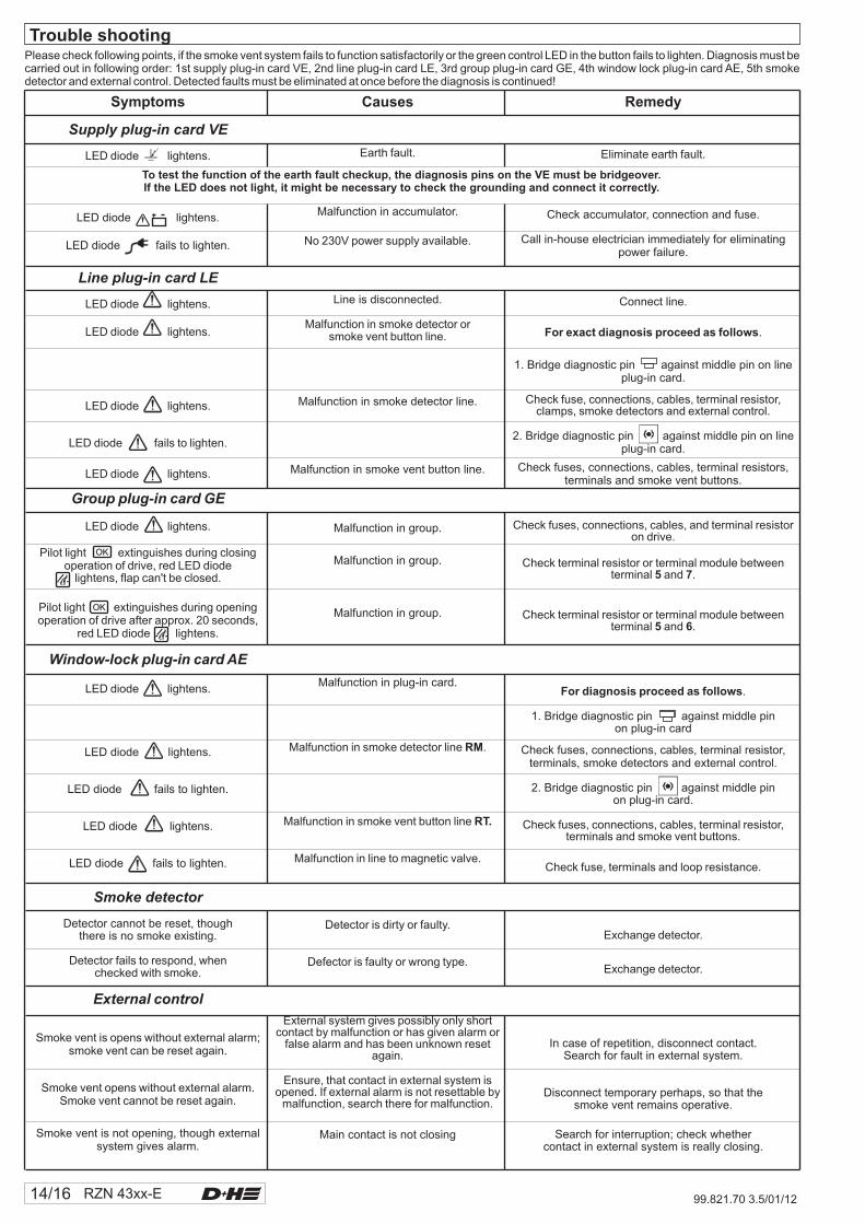
Please check following points, if the smoke vent system fails to function satisfactorily or the green control LED in the button fails to lighten. Diagnosis must becarried out in following order: 1st supply plug-in card VE, 2nd line plug-in card LE, 3rd group plug-in card GE, 4th window lock plug-in card AE, 5th smokedetector and external control. Detected faults must be eliminated at once before the diagnosis is continued!
Trouble shooting
To test the function of the earth fault checkup, the diagnosis pins on the VE must be bridgeover.If the LED does not light, it might be necessary to check the grounding and connect it correctly.
Symptoms
Supply plug-in card VE
Line plug-in card LE
Group plug-in card
Window-lock plug-in card
Smoke detector
External control
LED diode lightens.
LED diode lightens
LED diode fails to lighten
LED diode lightens
LED diode lightens.
LED diode lightens.
LED diode fails to lighten.
LED diode lightens.
LED diode lightens.
Pilot light extinguishes during closingoperation of drive, red LED diode
lightens, flap can't be closed.
Pilot light extinguishes during openingoperation of drive after approx. 20 seconds,
red LED diode lightens.
LED diode lightens.
LED diode lightens.
LED diode fails to lighten.
LED diode lightens.
LED diode fails to lighten.
Detector cannot be reset, thoughthere is no smoke existing.
Detector fails to respond, whenchecked with smoke.
Smoke vent is opens without external alarm;smoke vent can be reset again.
Smoke vent opens without external alarm.Smoke vent cannot be reset again.
Smoke vent is not opening, though externalsystem gives alarm.
.
.
.
GE
AE
Remedy
Eliminate earth fault.
Check accumulator, connection and fuse.
Call in-house electrician immediately for eliminatingpower failure.
Connect line.
.
1. Bridge diagnostic pin against middle pin on lineplug-in card.
Check fuse, connections, cables, t ,clamps, smoke detectors and external control.
2. Bridge diagnostic pin against middle pin on lineplug-in card.
Check fuses, connections, cables, terminal resistors,terminals and smoke vent buttons.
Check fuses, connections, cables, and ton drive.
Check t or terminal module betweenterminal and .
Check t or terminal module betweenterminal and .
.
1. Bridge diagnostic pin against middle pinon plug-in card
Check fuses, connections, cables, t ,terminals, smoke detectors and external control.
2. Bridge diagnostic pin against middle pinon plug-in card.
Check fuses, connections, cables, t ,terminals and smoke vent buttons.
Check fuse, terminals and loop resistance.
Exchange detector.
Exchange detector.
In case of repetition, disconnect contact.Search for fault in external system.
Disconnect temporary perhaps, so that thesmoke vent remains operative.
Search for interruption; check whethercontact in external system is really closing.
For exact diagnosis proceed as follows
5 7
5 6
For diagnosis proceed as follows
erminal resistor
erminal resistor
erminal resistor
erminal resistor
erminal resistor
erminal resistor
Causes
Earth fault.
Malfunction in accumulator
No 230V power supply available.
Line is disconnected
Malfunction in smoke detector orsmoke vent button line.
Malfunction in smoke detector line.
Malfunction in smoke vent button line.
Malfunction in group
Malfunction in group
Malfunction in group
Malfunction in plug-in card.
Malfunction in smoke detector line .
Malfunction in smoke vent button line
Malfunction in line to magnetic valve.
Detector is dirty or faulty.
Defector is faulty or wrong type.
External system gives possibly only shortcontact by malfunction or has given alarm or
false alarm and has been unknown resetagain.
Ensure, that contact in external system isopened. If external alarm is not resettable by
malfunction, search there for malfunction.
Main contact is not closing
.
.
.
.
.
RM
RT.
OK
OK
RZN 43xx-E 15/1699.821.70 3.5/01/12
Every six months and after maintenance carried out by a specialistengineer or trained staff.
Visual inspection:
Clamps and fastenings
Drives and smoke vent
Attention
Automatic fire detectors
Procedure in the case of alarm:
Do not carry out functional testing if
trigger plug-in card AE 526-DG is
installed for the control of 8 pressure
gas generators.
Closing after automatic release by smoke detector:
Procedure in the case of alarm with external control:
- Eliminate any errors immediately
- Fill out the logbook
- Advise that the system is going to be taken out of operation before starting
the inspection
- Inform the operating company that the alarm is going to be triggered for
equipment testing purposes
- Interrupt or turn off remote alarm reporting or remote control
Check all appliances and cable connections for outer damage and dirt
accumulation.
Fire detectors, smoke vent buttons, smoke vents and so on must not be
impaired in their function by goods in storage or structural changes.
-
Check connection terminals and fastenings of appliances that they are
securely seated.
-
In the case of excessive dirt accumulation and load, clean and re-grease
outer mechanically moved parts.
: Use only colourless fat-free Lusin A spray. Do not use any
grease so that dirt cannot stick.
-
In the case of severe externally visible dirt accumulation or false alarms,
send them in for maintenance and install an exchange detector. Check
detectors individually with D+H-smoke detector tester.
No possibility of functional testing. Triggering will lead to the destruction of
the pressure gas generators and sprinkler bottles as well as the emptying of
the CO cartouches. This will generate costs for exchange parts and the time
to install them. Shutdown of the system by a specialist company or trained
staff.
1. Open smoke vent button.
2. Open the system first with vent button and then close it again.
3. Trigger smoke detector with D+H-smoke detector tester.
4. Response delay approx. 20 seconds
5. Red display LED in the smoke vent button must light up.
6. Smoke vent opening must open.
1. Wait until there is no more smoke in detector. Switch the line on / off at the
control panel with reset button.
2. Press concealed button in smoke vent button; smoke vent closes.
3. Red display LED in button and on line plug-in unit goes out.
1. Trigger external control, if available.
2. Smoke vent opening must open.
2
Please note: Always activate another smoke vent button or smoke detector
for each line with every new test.
Closing after automatic triggering by external control:
Check alarm display and balanced running of all drives up to final
position.
Emergency supply:
Accumulator:
If the voltage of one
of the accumulators is less than 11V, both the accumulators must be
replaced.
1. Open contact in external system, e.g. by resetting the fire alarm system.
2. Press concealed button in smoke vent button; smoke vent closes.
3. Red display LED in button and on line plug-in unit goes out.
- Switch off main fuse at distribution box.
- Green control diode in smoke vent buttons should not light up.
Repeat functional testing.
- Green mains indication diode on control panel should not light up.
- Ventilation is out of service.
Yellow display LED on the central unit circuit board must light up.
- Check accumulator type.
- Contacts and housings must be clean and tight.
- Check fully charged accumulators that have not yet been used for correct
open-circuit and on-load voltage using D+H accumulator tester, in
accordance with the testing table:
- Measure the open-circuit voltage (alternatively using a digital
voltmeter); every accumulator must have between 13.5 and 13.9 V.
- Measure the on-load voltage. For this, open the system completely
twice via vent button. On the third time, measure the voltage during the
process.
The voltage of each accumulator must be at least 11 V.
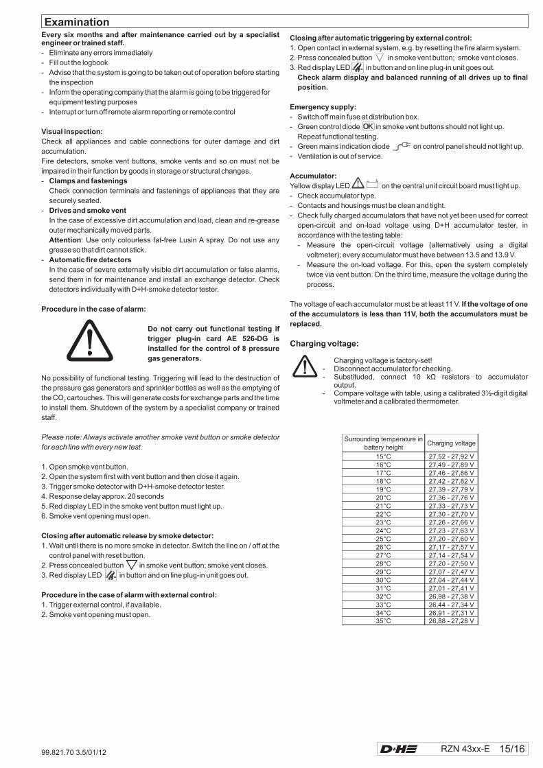
Charging voltage:
Charging voltage is factory-set!- Disconnect accumulator for checking.- Substituded
- Compare voltage with table, using a calibrated 3½-digit digitalvoltmeter and a calibrated thermometer.
, connect 10 kΩ resistors to accumulatoroutput.
Surrounding temperature inbattery height
Charging voltage
15°C 27,52 - 27,92 V16°C 27,49 - 27,89 V17°C 27,46 - 27,86 V18°C 27,42 - 27,82 V19°C 27,39 - 27,79 V20°C 27,36 - 27,76 V21°C 27,33 - 27,73 V22°C 27,30 - 27,70 V23°C 27,26 - 27,66 V24°C 27,23 - 27,63 V25°C 27,20 - 27,60 V26°C 27,17 - 27,57 V27°C 27,14 - 27,54 V28°C 27,20 - 27,50 V29°C 27,07 - 27,47 V30°C 27,04 - 27,44 V31°C 27,01 - 27,41 V32°C 26,98 - 27,38 V33°C 26,44 - 27,34 V34°C 26,91 - 27,31 V35°C 26,88 - 27,28 V
Examination
OK
OK

99.821.70 3.5/01/12
D+H MechatronicAGGeorg-Sasse-Str. 28-3222949Ammersbek
Tel. 40-605 65Fax 40-605 65 254
, Germany
: +49 239: +49
E-Mail: [email protected]
www.dh-partner.com© 2010 D+H Mechatronic AG, AmmersbekTechnische Änderungen vorbehalten. /Rights to technical modifications reserved.