Embed Size (px)
Citation preview
SMT & Area Array Rework
Solutions and systems for soldering, rework and repair of electronics
worldwide
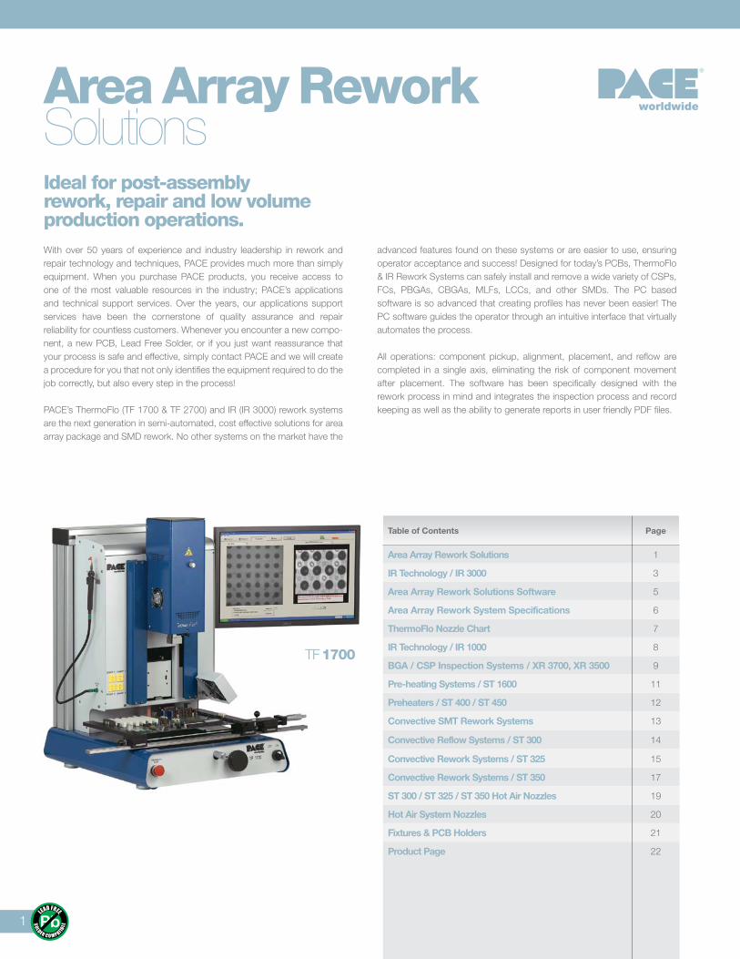
Table of Contents Page
Area Array Rework Solutions 1
IR Technology / IR 3000 3
Area Array Rework Solutions Software 5
Area Array Rework System Specifications 6
ThermoFlo Nozzle Chart 7
IR Technology / IR 1000 8
BGA / CSP Inspection Systems / XR 3700, XR 3500 9
Pre-heating Systems / ST 1600 11
Preheaters / ST 400 / ST 450 12
Convective SMT Rework Systems 13
Convective Reflow Systems / ST 300 14
Convective Rework Systems / ST 325 15
Convective Rework Systems / ST 350 17
ST 300 / ST 325 / ST 350 Hot Air Nozzles 19
Hot Air System Nozzles 20
Fixtures & PCB Holders 21
Product Page 22
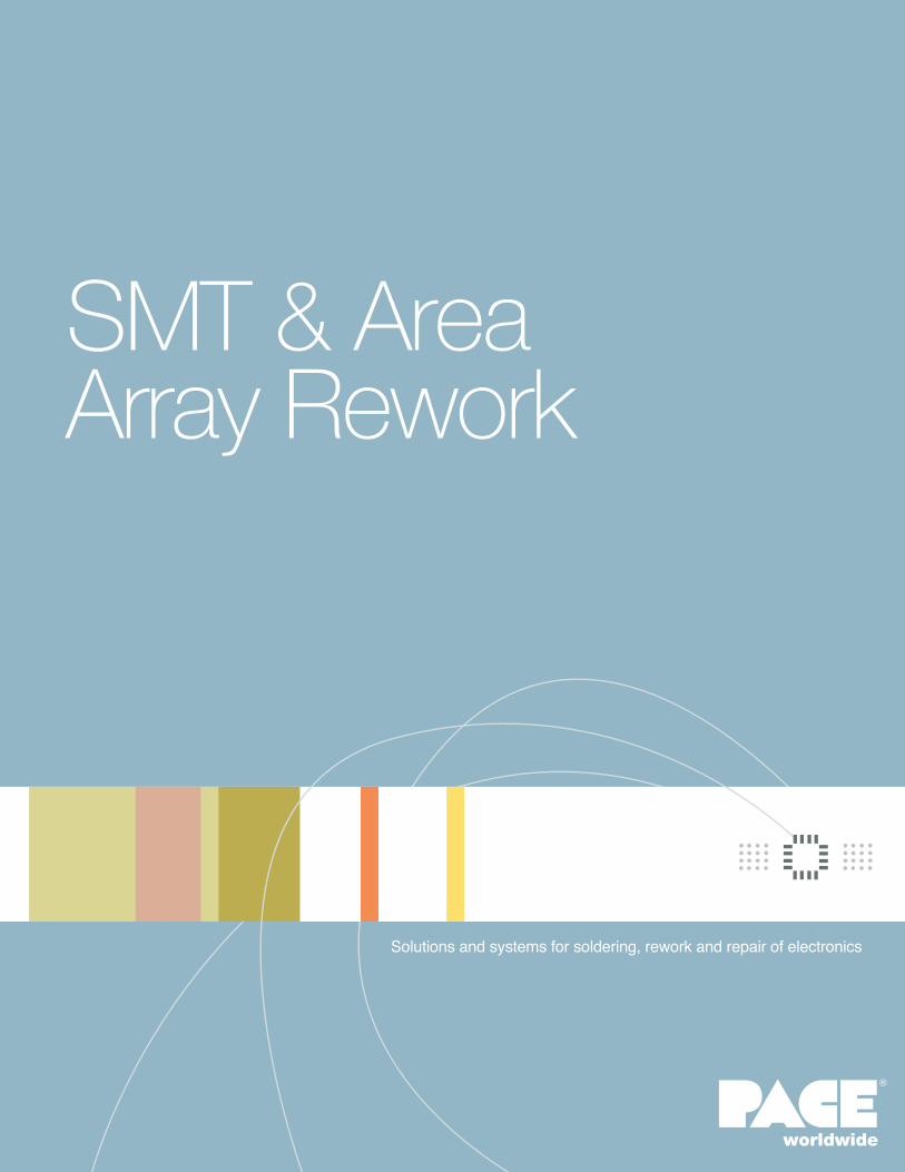
With over 50 years of experience and industry leadership in rework and repair technology and techniques, PACE provides much more than simply equipment. When you purchase PACE products, you receive access to one of the most valuable resources in the industry; PACE’s applications and technical support services. Over the years, our applications support services have been the cornerstone of quality assurance and repair reliability for countless customers. Whenever you encounter a new compo-nent, a new PCB, Lead Free Solder, or if you just want reassurance that your process is safe and effective, simply contact PACE and we will create a procedure for you that not only identifies the equipment required to do the job correctly, but also every step in the process!
PACE’s ThermoFlo (TF 1700 & TF 2700) and IR (IR 3000) rework systems are the next generation in semi-automated, cost effective solutions for area array package and SMD rework. No other systems on the market have the
advanced features found on these systems or are easier to use, ensuring operator acceptance and success! Designed for today’s PCBs, ThermoFlo & IR Rework Systems can safely install and remove a wide variety of CSPs, FCs, PBGAs, CBGAs, MLFs, LCCs, and other SMDs. The PC based software is so advanced that creating profiles has never been easier! The PC software guides the operator through an intuitive interface that virtually automates the process.
All operations: component pickup, alignment, placement, and reflow are completed in a single axis, eliminating the risk of component movement after placement. The software has been specifically designed with the rework process in mind and integrates the inspection process and record keeping as well as the ability to generate reports in user friendly PDF files.
Area Array Rework Solutions
1
worldwide
TF 1700
Ideal for post-assembly rework, repair and low volume production operations.
Heating TechnologyThermoFlo systems are fitted with a custom designed 1200 watt top-side heater and an incredibly efficient IR bottom-side heating platform that is adjustable when more power is required for challenging applications. They combine convective top-side heating with remarkably stable and powerful IR bottom-side heating for the most effective, repeatable heating process available today. The bottom-side heater(s) can be adjusted from its standard position up to 38mm (1.5") closer to the PCB for those challenging appli-cations where additional heat is desired or needed! This is a unique PACE feature designed especially for use with Lead Free processes.
The IR 3000 features medium/long wavelength heaters that respond faster with more power than any ceramic or carbon IR emitter currently available. The bottom heater features high power, quick response quartz IR emitters,
and share the adjustability feature of the ThermoFlo units. Each process is controlled in real time using a specialized IR sensor.
The PCB holder for all 3 units features fine micrometer adjustment for the most delicate X and Y axis alignments. Precise and accurate, within 25 μm (.001"), Z axis movement is ensured through a twin rail, linear bearing motion control assembly that is similar to those used on automated pick and place equipment. The optical alignment system utilizes advanced digital, color cameras and the highest quality prism available for amazing image clarity. All systems are self-contained and do not require an external air supply or vacuum connections. Upgrade your area array rework capabilities and through-put with PACE’s ThermoFlo or IR systems!
2
TF 2700
IRTechnology
3
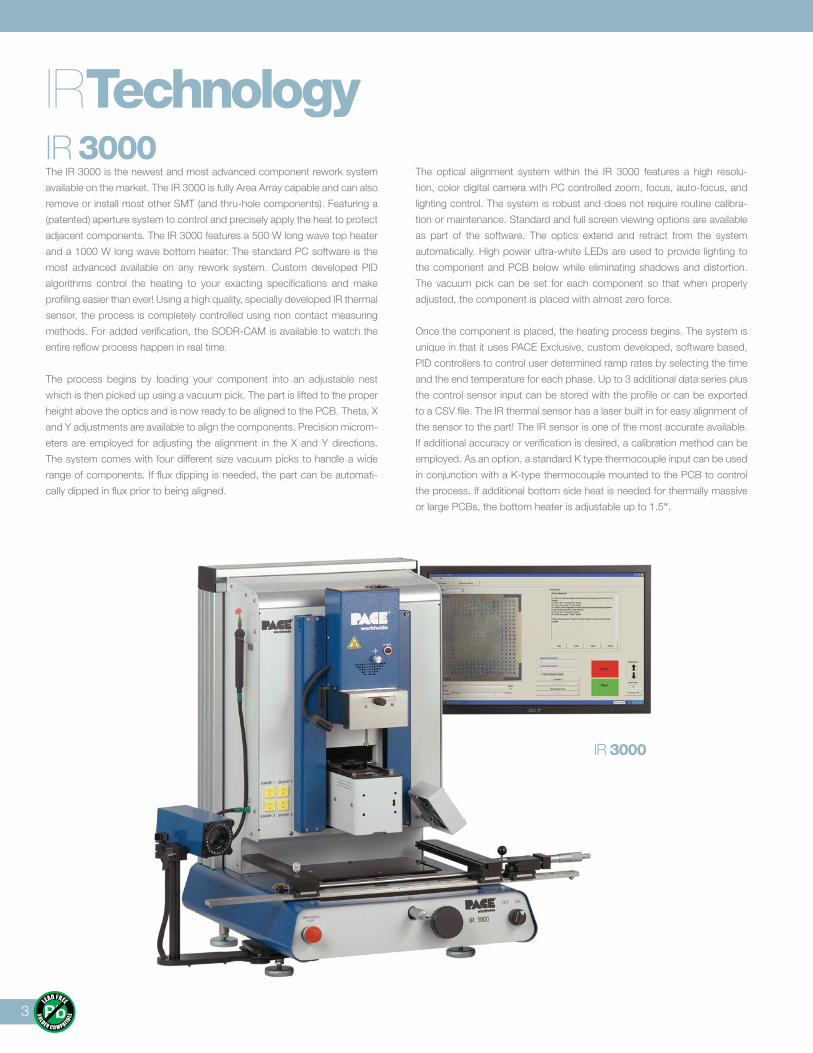
IR 3000The IR 3000 is the newest and most advanced component rework system
available on the market. The IR 3000 is fully Area Array capable and can also
remove or install most other SMT (and thru-hole components). Featuring a
(patented) aperture system to control and precisely apply the heat to protect
adjacent components. The IR 3000 features a 500 W long wave top heater
and a 1000 W long wave bottom heater. The standard PC software is the
most advanced available on any rework system. Custom developed PID
algorithms control the heating to your exacting specifications and make
profiling easier than ever! Using a high quality, specially developed IR thermal
sensor, the process is completely controlled using non contact measuring
methods. For added verification, the SODR-CAM is available to watch the
entire reflow process happen in real time.
The process begins by loading your component into an adjustable nest
which is then picked up using a vacuum pick. The part is lifted to the proper
height above the optics and is now ready to be aligned to the PCB. Theta, X
and Y adjustments are available to align the components. Precision microm-
eters are employed for adjusting the alignment in the X and Y directions.
The system comes with four different size vacuum picks to handle a wide
range of components. If flux dipping is needed, the part can be automati-
cally dipped in flux prior to being aligned.
The optical alignment system within the IR 3000 features a high resolu-
tion, color digital camera with PC controlled zoom, focus, auto-focus, and
lighting control. The system is robust and does not require routine calibra-
tion or maintenance. Standard and full screen viewing options are available
as part of the software. The optics extend and retract from the system
automatically. High power ultra-white LEDs are used to provide lighting to
the component and PCB below while eliminating shadows and distortion.
The vacuum pick can be set for each component so that when properly
adjusted, the component is placed with almost zero force.
Once the component is placed, the heating process begins. The system is
unique in that it uses PACE Exclusive, custom developed, software based,
PID controllers to control user determined ramp rates by selecting the time
and the end temperature for each phase. Up to 3 additional data series plus
the control sensor input can be stored with the profile or can be exported
to a CSV file. The IR thermal sensor has a laser built in for easy alignment of
the sensor to the part! The IR sensor is one of the most accurate available.
If additional accuracy or verification is desired, a calibration method can be
employed. As an option, a standard K type thermocouple input can be used
in conjunction with a K-type thermocouple mounted to the PCB to control
the process. If additional bottom side heat is needed for thermally massive
or large PCBs, the bottom heater is adjustable up to 1.5".
IR 3000
ComponentPick-up, Align, Reflow
4
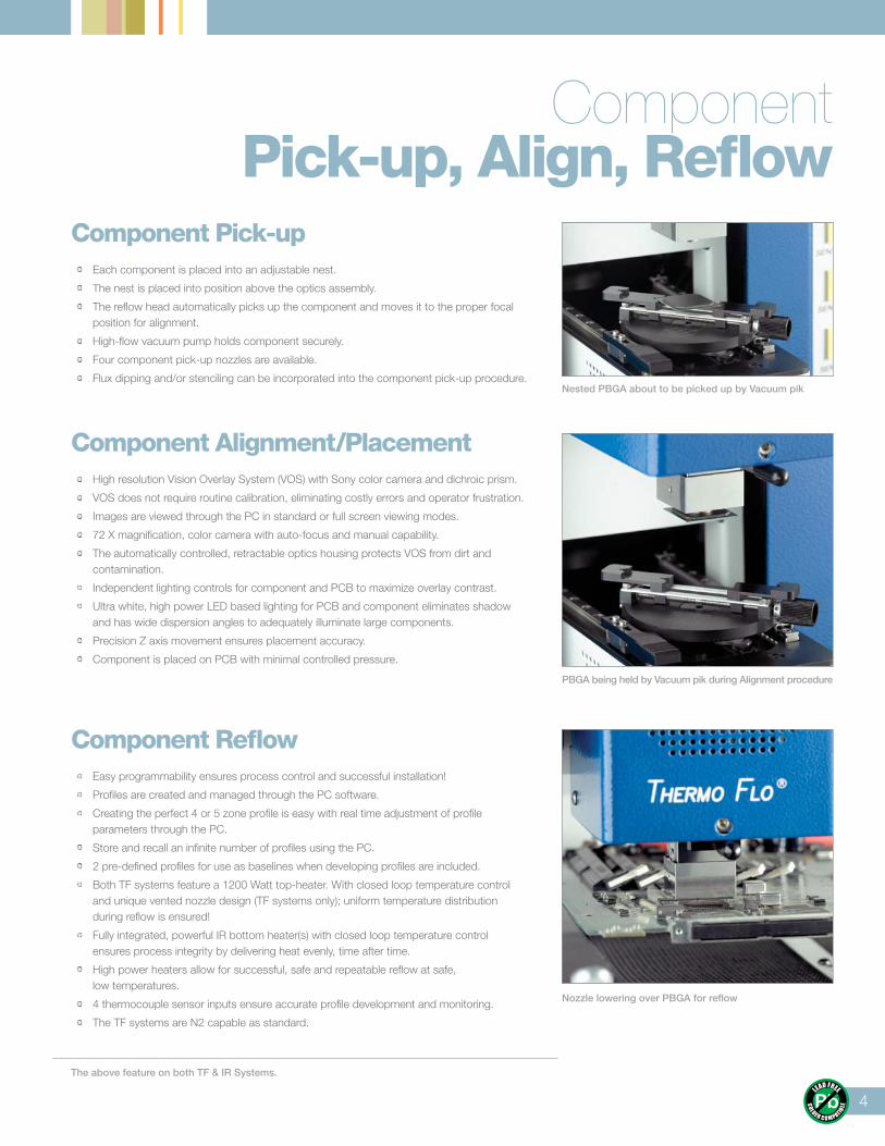
Component Pick-up • Each component is placed into an adjustable nest.
• The nest is placed into position above the optics assembly.
• The reflow head automatically picks up the component and moves it to the proper focal position for alignment.
• High-flow vacuum pump holds component securely.
• Four component pick-up nozzles are available.
• Flux dipping and/or stenciling can be incorporated into the component pick-up procedure.
Component Alignment/Placement • High resolution Vision Overlay System (VOS) with Sony color camera and dichroic prism.
• VOS does not require routine calibration, eliminating costly errors and operator frustration.
• Images are viewed through the PC in standard or full screen viewing modes.
• 72 X magnification, color camera with auto-focus and manual capability.
• The automatically controlled, retractable optics housing protects VOS from dirt and contamination.
• Independent lighting controls for component and PCB to maximize overlay contrast.
• Ultra white, high power LED based lighting for PCB and component eliminates shadow and has wide dispersion angles to adequately illuminate large components.
• Precision Z axis movement ensures placement accuracy.
• Component is placed on PCB with minimal controlled pressure.
Component Reflow • Easy programmability ensures process control and successful installation!
• Profiles are created and managed through the PC software.
• Creating the perfect 4 or 5 zone profile is easy with real time adjustment of profile parameters through the PC.
• Store and recall an infinite number of profiles using the PC.
• 2 pre-defined profiles for use as baselines when developing profiles are included.
• Both TF systems feature a 1200 Watt top-heater. With closed loop temperature control and unique vented nozzle design (TF systems only); uniform temperature distribution during reflow is ensured!
• Fully integrated, powerful IR bottom heater(s) with closed loop temperature control ensures process integrity by delivering heat evenly, time after time.
• High power heaters allow for successful, safe and repeatable reflow at safe, low temperatures.
• 4 thermocouple sensor inputs ensure accurate profile development and monitoring.
• The TF systems are N2 capable as standard.
Nested PBGA about to be picked up by Vacuum pik
PBGA being held by Vacuum pik during Alignment procedure
Nozzle lowering over PBGA for reflow
The above feature on both TF & IR Systems.
5
Area Array ReworkSolutions Software
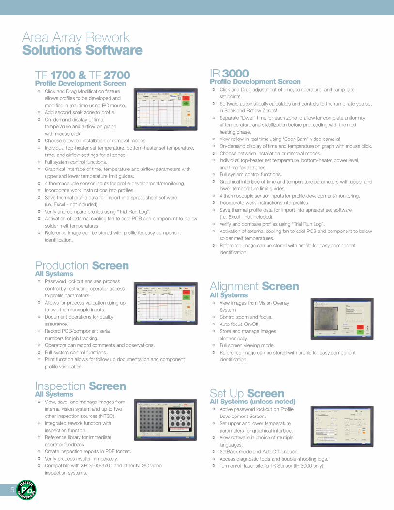
TF 1700 & TF 2700 Profile Development Screen • Click and Drag Modification feature
allows profiles to be developed and modified in real time using PC mouse.
• Add second soak zone to profile. • On-demand display of time,
temperature and airflow on graph with mouse click.
• Choose between installation or removal modes. • Individual top-heater set temperature, bottom-heater set temperature,
time, and airflow settings for all zones. • Full system control functions. • Graphical interface of time, temperature and airflow parameters with
upper and lower temperature limit guides. • 4 thermocouple sensor inputs for profile development/monitoring. • Incorporate work instructions into profiles. • Save thermal profile data for import into spreadsheet software
(i.e. Excel - not included). • Verify and compare profiles using “Trial Run Log”. • Activation of external cooling fan to cool PCB and component to below
solder melt temperatures. • Reference image can be stored with profile for easy component
identification.
Production ScreenAll Systems • Password lockout ensures process
control by restricting operator access to profile parameters.
• Allows for process validation using up to two thermocouple inputs.
• Document operations for quality assurance.
• Record PCB/component serial numbers for job tracking.
• Operators can record comments and observations. • Full system control functions. • Print function allows for follow up documentation and component
profile verification.
Inspection ScreenAll Systems • View, save, and manage images from
internal vision system and up to two other inspection sources (NTSC).
• Integrated rework function with inspection function.
• Reference library for immediate operator feedback.
• Create inspection reports in PDF format. • Verify process results immediately. • Compatible with XR 3500/3700 and other NTSC video
inspection systems.
IR 3000Profile Development Screen • Click and Drag adjustment of time, temperature, and ramp rate
set points. • Software automatically calculates and controls to the ramp rate you set
in Soak and Reflow Zones! • Separate “Dwell” time for each zone to allow for complete uniformity
of temperature and stabilization before proceeding with the next heating phase.
• View reflow in real time using “Sodr-Cam” video camera! • On-demand display of time and temperature on graph with mouse click. • Choose between installation or removal modes. • Individual top-heater set temperature, bottom-heater power level,
and time for all zones. • Full system control functions. • Graphical interface of time and temperature parameters with upper and
lower temperature limit guides. • 4 thermocouple sensor inputs for profile development/monitoring. • Incorporate work instructions into profiles. • Save thermal profile data for import into spreadsheet software
(i.e. Excel - not included). • Verify and compare profiles using “Trial Run Log”. • Activation of external cooling fan to cool PCB and component to below
solder melt temperatures. • Reference image can be stored with profile for easy component
identification.
Alignment Screen All Systems • View images from Vision Overlay
System. • Control zoom and focus. • Auto focus On/Off. • Store and manage images
electronically. • Full screen viewing mode. • Reference image can be stored with profile for easy component
identification.
Set Up ScreenAll Systems (unless noted) • Active password lockout on Profile
Development Screen. • Set upper and lower temperature
parameters for graphical interface. • View software in choice of multiple
languages. • SetBack mode and AutoOff function. • Access diagnostic tools and trouble-shooting logs. • Turn on/off laser site for IR Sensor (IR 3000 only).
6
Area Array ReworkSystem Specifications
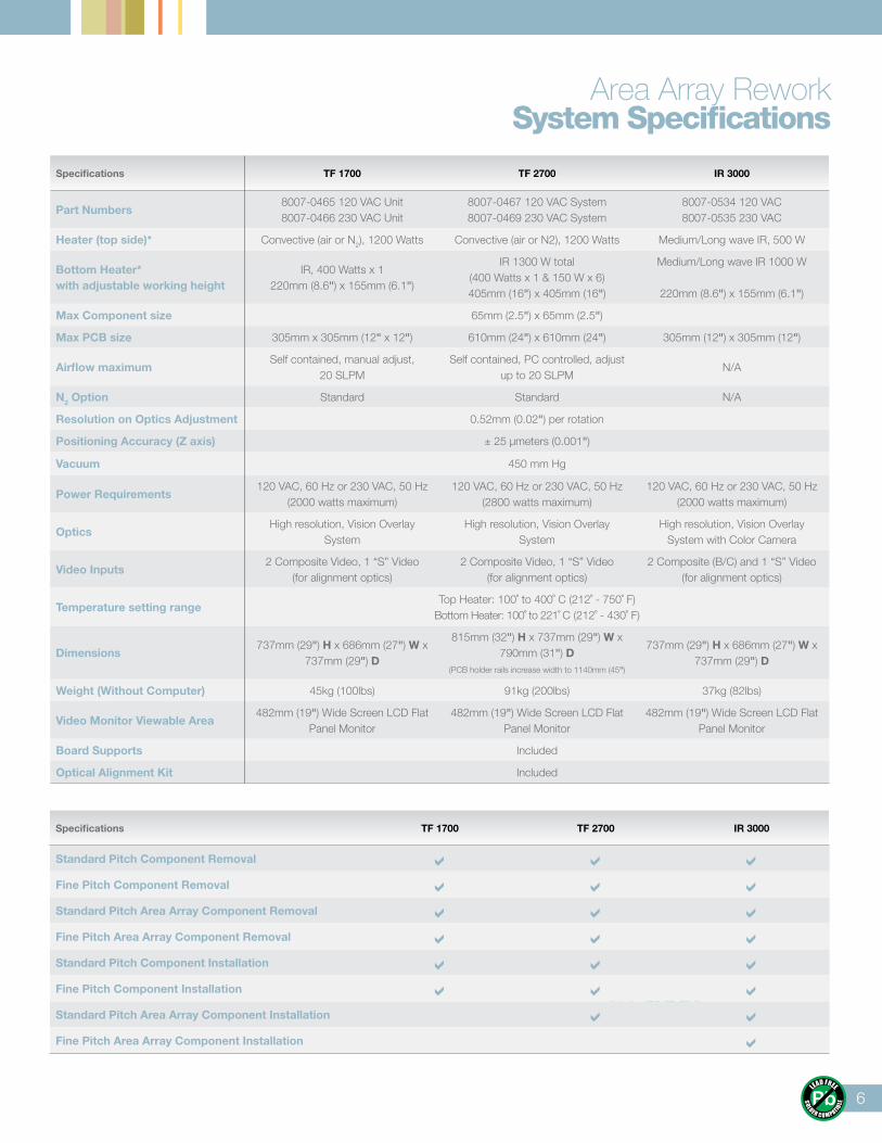
Specifications TF 1700 TF 2700 IR 3000
Part Numbers8007-0465 120 VAC Unit8007-0466 230 VAC Unit
8007-0467 120 VAC System8007-0469 230 VAC System
8007-0534 120 VAC8007-0535 230 VAC
Heater (top side)* Convective (air or N2), 1200 Watts Convective (air or N2), 1200 Watts Medium/Long wave IR, 500 W
Bottom Heater*with adjustable working height
IR, 400 Watts x 1220mm (8.6") x 155mm (6.1")
IR 1300 W total(400 Watts x 1 & 150 W x 6)405mm (16") x 405mm (16")
Medium/Long wave IR 1000 W
220mm (8.6") x 155mm (6.1")
Max Component size 65mm (2.5") x 65mm (2.5")
Max PCB size 305mm x 305mm (12" x 12") 610mm (24") x 610mm (24") 305mm (12") x 305mm (12")
Airflow maximumSelf contained, manual adjust,
20 SLPMSelf contained, PC controlled, adjust
up to 20 SLPMN/A
N2 Option Standard Standard N/A
Resolution on Optics Adjustment 0.52mm (0.02") per rotation
Positioning Accuracy (Z axis) ± 25 μmeters (0.001")
Vacuum 450 mm Hg
Power Requirements120 VAC, 60 Hz or 230 VAC, 50 Hz
(2000 watts maximum)120 VAC, 60 Hz or 230 VAC, 50 Hz
(2800 watts maximum)120 VAC, 60 Hz or 230 VAC, 50 Hz
(2000 watts maximum)
OpticsHigh resolution, Vision Overlay
SystemHigh resolution, Vision Overlay
SystemHigh resolution, Vision Overlay
System with Color Camera
Video Inputs2 Composite Video, 1 “S” Video
(for alignment optics)2 Composite Video, 1 “S” Video
(for alignment optics)2 Composite (B/C) and 1 “S” Video
(for alignment optics)
Temperature setting rangeTop Heater: 100˚ to 400˚ C (212˚ - 750˚ F)
Bottom Heater: 100˚ to 221˚ C (212˚ - 430˚ F)
Dimensions737mm (29") H x 686mm (27") W x
737mm (29") D
815mm (32") H x 737mm (29") W x 790mm (31") D
(PCB holder rails increase width to 1140mm (45")
737mm (29") H x 686mm (27") W x 737mm (29") D
Weight (Without Computer) 45kg (100lbs) 91kg (200lbs) 37kg (82lbs)
Video Monitor Viewable Area482mm (19") Wide Screen LCD Flat
Panel Monitor482mm (19") Wide Screen LCD Flat
Panel Monitor482mm (19") Wide Screen LCD Flat
Panel Monitor
Board Supports Included
Optical Alignment Kit Included
XR 3000
Specifications TF 1700 TF 2700 IR 3000
Standard Pitch Component Removal Fine Pitch Component Removal Standard Pitch Area Array Component Removal Fine Pitch Area Array Component Removal Standard Pitch Component Installation Fine Pitch Component Installation Standard Pitch Area Array Component Installation Fine Pitch Area Array Component Installation
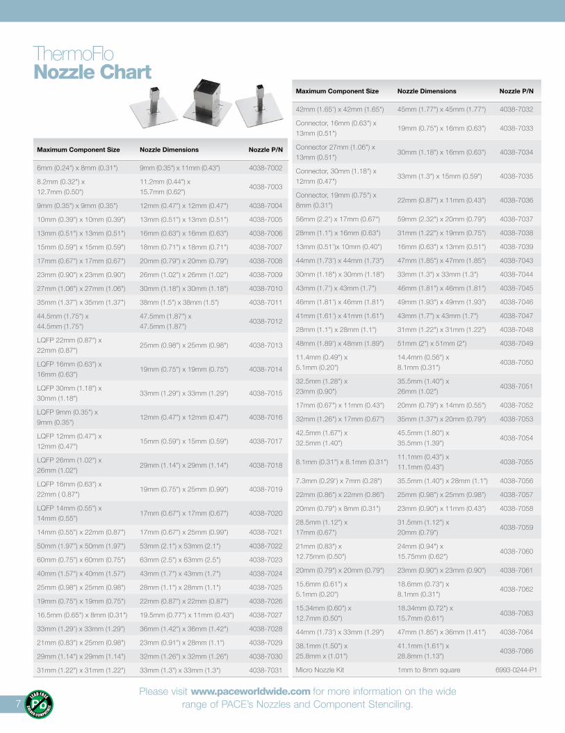
ThermoFloNozzle Chart
Maximum Component Size Nozzle Dimensions Nozzle P/N
6mm (0.24") x 8mm (0.31") 9mm (0.35") x 11mm (0.43") 4038-7002
8.2mm (0.32") x 12.7mm (0.50")
11.2mm (0.44") x 15.7mm (0.62")
4038-7003
9mm (0.35") x 9mm (0.35") 12mm (0.47") x 12mm (0.47") 4038-7004
10mm (0.39") x 10mm (0.39") 13mm (0.51") x 13mm (0.51") 4038-7005
13mm (0.51") x 13mm (0.51") 16mm (0.63") x 16mm (0.63") 4038-7006
15mm (0.59") x 15mm (0.59") 18mm (0.71") x 18mm (0.71") 4038-7007
17mm (0.67") x 17mm (0.67") 20mm (0.79") x 20mm (0.79") 4038-7008
23mm (0.90") x 23mm (0.90") 26mm (1.02") x 26mm (1.02") 4038-7009
27mm (1.06") x 27mm (1.06") 30mm (1.18") x 30mm (1.18") 4038-7010
35mm (1.37”) x 35mm (1.37") 38mm (1.5") x 38mm (1.5") 4038-7011
44.5mm (1.75") x44.5mm (1.75")
47.5mm (1.87") x 47.5mm (1.87")
4038-7012
LQFP 22mm (0.87") x 22mm (0.87")
25mm (0.98") x 25mm (0.98") 4038-7013
LQFP 16mm (0.63") x 16mm (0.63")
19mm (0.75") x 19mm (0.75") 4038-7014
LQFP 30mm (1.18") x30mm (1.18")
33mm (1.29") x 33mm (1.29") 4038-7015
LQFP 9mm (0.35") x 9mm (0.35")
12mm (0.47") x 12mm (0.47") 4038-7016
LQFP 12mm (0.47") x 12mm (0.47")
15mm (0.59") x 15mm (0.59") 4038-7017
LQFP 26mm (1.02") x26mm (1.02")
29mm (1.14") x 29mm (1.14") 4038-7018
LQFP 16mm (0.63") x 22mm ( 0.87")
19mm (0.75") x 25mm (0.99") 4038-7019
LQFP 14mm (0.55") x 14mm (0.55")
17mm (0.67") x 17mm (0.67") 4038-7020
14mm (0.55") x 22mm (0.87") 17mm (0.67") x 25mm (0.99") 4038-7021
50mm (1.97”) x 50mm (1.97") 53mm (2.1") x 53mm (2.1") 4038-7022
60mm (0.75”) x 60mm (0.75") 63mm (2.5") x 63mm (2.5") 4038-7023
40mm (1.57") x 40mm (1.57") 43mm (1.7") x 43mm (1.7") 4038-7024
25mm (0.98") x 25mm (0.98") 28mm (1.1") x 28mm (1.1") 4038-7025
19mm (0.75") x 19mm (0.75") 22mm (0.87") x 22mm (0.87") 4038-7026
16.5mm (0.65") x 8mm (0.31") 19.5mm (0.77") x 11mm (0.43") 4038-7027
33mm (1.29") x 33mm (1.29") 36mm (1.42") x 36mm (1.42") 4038-7028
21mm (0.83") x 25mm (0.98") 23mm (0.91") x 28mm (1.1") 4038-7029
29mm (1.14") x 29mm (1.14") 32mm (1.26") x 32mm (1.26") 4038-7030
31mm (1.22") x 31mm (1.22") 33mm (1.3") x 33mm (1.3") 4038-7031
Maximum Component Size Nozzle Dimensions Nozzle P/N
42mm (1.65") x 42mm (1.65") 45mm (1.77") x 45mm (1.77") 4038-7032
Connector, 16mm (0.63") x 13mm (0.51")
19mm (0.75") x 16mm (0.63") 4038-7033
Connector 27mm (1.06") x 13mm (0.51")
30mm (1.18") x 16mm (0.63") 4038-7034
Connector, 30mm (1.18") x 12mm (0.47")
33mm (1.3") x 15mm (0.59") 4038-7035
Connector, 19mm (0.75") x 8mm (0.31")
22mm (0.87") x 11mm (0.43") 4038-7036
56mm (2.2") x 17mm (0.67") 59mm (2.32") x 20mm (0.79") 4038-7037
28mm (1.1") x 16mm (0.63") 31mm (1.22") x 19mm (0.75") 4038-7038
13mm (0.51")x 10mm (0.40") 16mm (0.63") x 13mm (0.51") 4038-7039
44mm (1.73") x 44mm (1.73") 47mm (1.85") x 47mm (1.85") 4038-7043
30mm (1.18") x 30mm (1.18") 33mm (1.3") x 33mm (1.3") 4038-7044
43mm (1.7") x 43mm (1.7") 46mm (1.81") x 46mm (1.81") 4038-7045
46mm (1.81") x 46mm (1.81") 49mm (1.93") x 49mm (1.93") 4038-7046
41mm (1.61") x 41mm (1.61") 43mm (1.7") x 43mm (1.7") 4038-7047
28mm (1.1") x 28mm (1.1") 31mm (1.22") x 31mm (1.22") 4038-7048
48mm (1.89") x 48mm (1.89") 51mm (2") x 51mm (2") 4038-7049
11.4mm (0.49") x 5.1mm (0.20")
14.4mm (0.56") x 8.1mm (0.31")
4038-7050
32.5mm (1.28") x 23mm (0.90")
35.5mm (1.40") x 26mm (1.02")
4038-7051
17mm (0.67") x 11mm (0.43") 20mm (0.79") x 14mm (0.55") 4038-7052
32mm (1.26") x 17mm (0.67") 35mm (1.37") x 20mm (0.79") 4038-7053
42.5mm (1.67") x32.5mm (1.40")
45.5mm (1.80") x 35.5mm (1.39")
4038-7054
8.1mm (0.31") x 8.1mm (0.31")11.1mm (0.43") x 11.1mm (0.43")
4038-7055
7.3mm (0.29") x 7mm (0.28") 35.5mm (1.40") x 28mm (1.1") 4038-7056
22mm (0.86") x 22mm (0.86") 25mm (0.98") x 25mm (0.98") 4038-7057
20mm (0.79") x 8mm (0.31") 23mm (0.90") x 11mm (0.43") 4038-7058
28.5mm (1.12") x 17mm (0.67")
31.5mm (1.12") x 20mm (0.79")
4038-7059
21mm (0.83") x 12.75mm (0.50")
24mm (0.94") x 15.75mm (0.62")
4038-7060
20mm (0.79") x 20mm (0.79") 23mm (0.90") x 23mm (0.90") 4038-7061
15.6mm (0.61") x 5.1mm (0.20")
18.6mm (0.73") x 8.1mm (0.31")
4038-7062
15.34mm (0.60") x 12.7mm (0.50")
18.34mm (0.72") x 15.7mm (0.61")
4038-7063
44mm (1.73") x 33mm (1.29") 47mm (1.85") x 36mm (1.41") 4038-7064
38.1mm (1.50") x 25.8mm x (1.01")
41.1mm (1.61") x 28.8mm (1.13")
4038-7066
Micro Nozzle Kit 1mm to 8mm square 6993-0244-P1
Please visit www.paceworldwide.com for more information on the wide range of PACE’s Nozzles and Component Stenciling.7
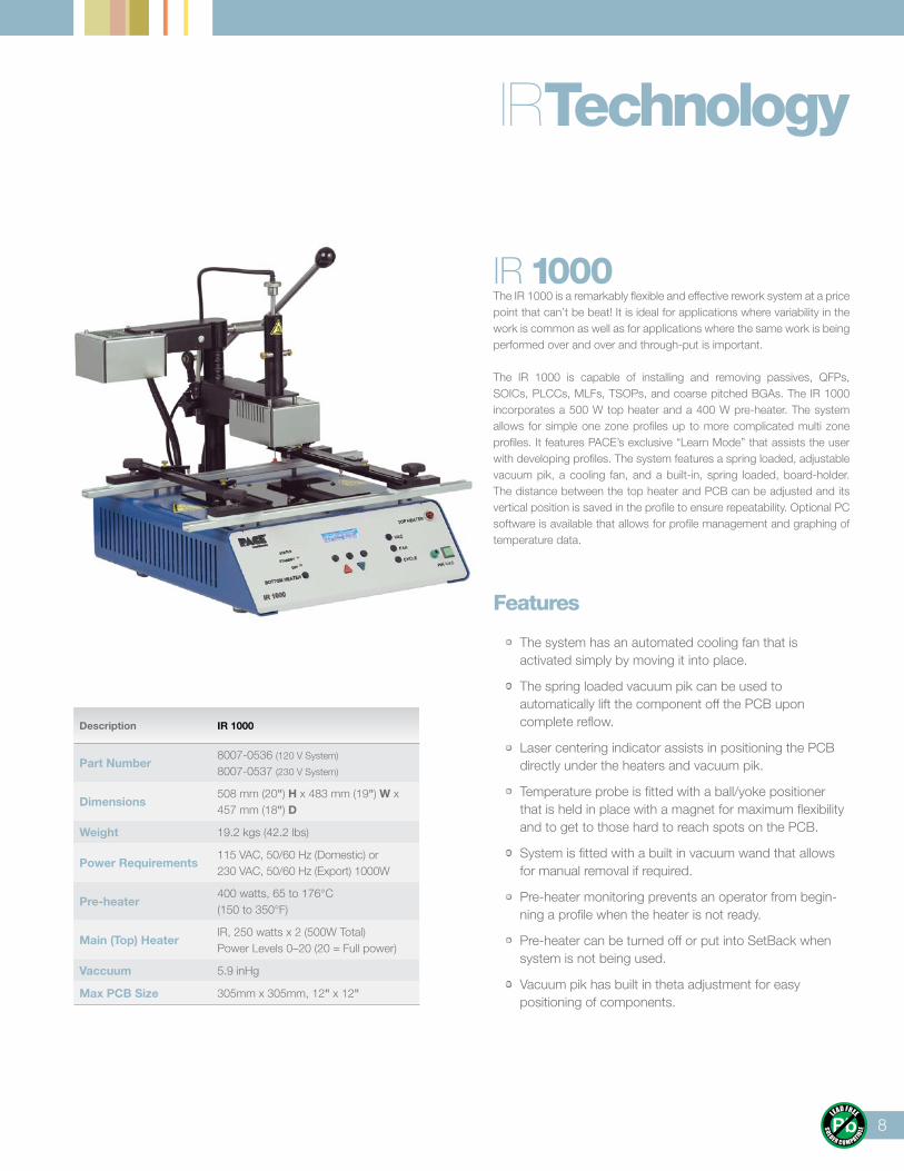
IR 1000The IR 1000 is a remarkably flexible and effective rework system at a price point that can’t be beat! It is ideal for applications where variability in the work is common as well as for applications where the same work is being performed over and over and through-put is important.
The IR 1000 is capable of installing and removing passives, QFPs, SOICs, PLCCs, MLFs, TSOPs, and coarse pitched BGAs. The IR 1000 incorporates a 500 W top heater and a 400 W pre-heater. The system allows for simple one zone profiles up to more complicated multi zone profiles. It features PACE’s exclusive “Learn Mode” that assists the user with developing profiles. The system features a spring loaded, adjustable vacuum pik, a cooling fan, and a built-in, spring loaded, board-holder. The distance between the top heater and PCB can be adjusted and its vertical position is saved in the profile to ensure repeatability. Optional PC software is available that allows for profile management and graphing of temperature data.
Features
• The system has an automated cooling fan that is activated simply by moving it into place.
• The spring loaded vacuum pik can be used to automatically lift the component off the PCB upon complete reflow.
• Laser centering indicator assists in positioning the PCB directly under the heaters and vacuum pik.
• Temperature probe is fitted with a ball/yoke positioner that is held in place with a magnet for maximum flexibility and to get to those hard to reach spots on the PCB.
• System is fitted with a built in vacuum wand that allows for manual removal if required.
• Pre-heater monitoring prevents an operator from begin-ning a profile when the heater is not ready.
• Pre-heater can be turned off or put into SetBack when system is not being used.
• Vacuum pik has built in theta adjustment for easy positioning of components.
Description IR 1000
Part Number8007-0536 (120 V System) 8007-0537 (230 V System)
Dimensions508 mm (20") H x 483 mm (19") W x 457 mm (18") D
Weight 19.2 kgs (42.2 lbs)
Power Requirements115 VAC, 50/60 Hz (Domestic) or230 VAC, 50/60 Hz (Export) 1000W
Pre-heater400 watts, 65 to 176°C(150 to 350°F)
Main (Top) HeaterIR, 250 watts x 2 (500W Total) Power Levels 0–20 (20 = Full power)
Vaccuum 5.9 inHg
Max PCB Size 305mm x 305mm, 12" x 12"
IRTechnology
8
9
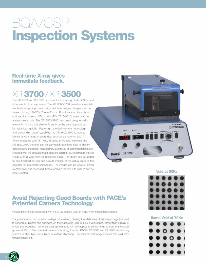
BGA/CSPInspection Systems
Avoid Rejecting Good Boards with PACE’s Patented Camera TechnologyVoltage blooming is associated with the X-ray camera used in many X-ray inspection systems.
The phenomenon occurs when voltage is increased, causing the white area of the X-ray image (the void) to expand (or bloom) and encroach on the black area. This makes a void appear larger than it really is. A void that occupies 10% of a solder sphere at 50 kV may appear to consume up to 50% of the solder sphere at 70 kV. The patented camera technology found in PACE’s XR 3500 and XR 3700 are the only systems of their type not subject to Voltage Blooming. The camera technology ensures that void sizes remain consistent.
Void at 50Kv
Same Void at 70Kv
Real-time X-ray gives immediate feedback.
XR 3700 / XR 3500The XR 3500 and XR 3700 are ideal for inspecting BGAs, CSPs, and
other electronic components. The XR 3500/3700 provides immediate
feedback on your process using real time images. Images can be
viewed through PACE’s ThermoFlo or IR software or through an
optional, flat screen, LCD monitor (P/N 7015-0010) when used as
a stand-alone unit. The XR 3500/3700 has been designed with
rework in mind so it is able to fit easily on the benchtop and can
be relocated quickly. Featuring patented camera technology
and outstanding zoom capability, the XR 3500/3700 is able to
identify a wide range of anomalies, as small as .025mm (.001").
When integrated with TF 1700, TF 2700 or IR 3000 software, the
XR 3500/3700 systems can actually teach operators how to identify
defects using the defect image library. Examples of common defects are
included with the software that operators can refer to, to compare the live
image of their work with the reference image. The library can be added
to and modified so you can provide images of the actual work to the
operator for immediate comparison. The images can be viewed, stored
electronically, and managed. Defect analysis reports with images can be
easily created.
10
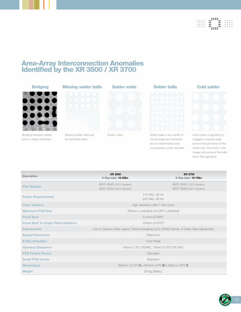
Area-Array Interconnection Anomalies Identified by the XR 3500 / XR 3700
Bridging between solder
joints is easily identified.
Bridging
Missing solder balls can
be identified easily.
Missing solder balls
Solder voids.
Solder voids
Solder balls in the center of
the package are oversized
due to delamination and
compression under die area.
Solder balls
Cold solder is signified by
a jagged, irregular edge
around the perimeter of the
solder ball. Note that in this
image only some of the balls
show this signature.
Cold solder
Description XR 3500
X-Ray tube: 10-50kv XR 3700
X-Ray tube: 10-70kv
Part Number8007-0540 (120 V System)
8007-0544 (230 V System)
8007-0542 (120 V System)
8007-0546 (230 V System)
Power Requirements115 VAC, 60 Hz230 VAC, 60 Hz
Color Camera High resolution with 7-40x zoom
Maximum PCB Size 760mm x unlimited mm (30" x unlimited)
Focal Spot 0.2mm (0.008")
Focal Spot To Image Plane Distance 124mm (4.875")
Adjustments Live or Capture video signal, Frame averaging up to 32000 frames, & Video Gain adjustment
Spatial Resolution 20lp/mmv
X-Ray Actuation Foot Pedal
Opening Clearance 40mm (1.5") 120VAC, 19mm (0.75") 230 VAC
PCB Fixture Device Standard
Small PCB Carrier Standard
Dimensions 394mm (15.5") H x 457mm (18") W x 585mm (23") D
Weight 39 Kg (86lbs.)
11
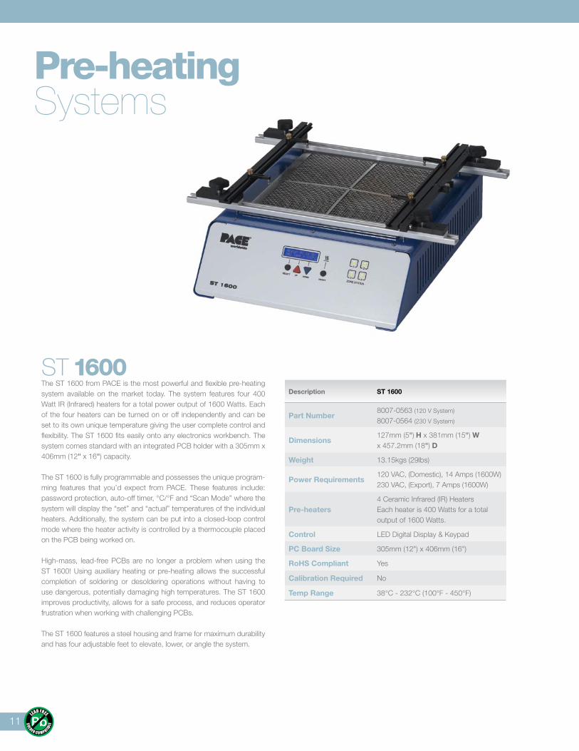
ST 1600The ST 1600 from PACE is the most powerful and flexible pre-heating system available on the market today. The system features four 400 Watt IR (Infrared) heaters for a total power output of 1600 Watts. Each of the four heaters can be turned on or off independently and can be set to its own unique temperature giving the user complete control and flexibility. The ST 1600 fits easily onto any electronics workbench. The system comes standard with an integrated PCB holder with a 305mm x 406mm (12" x 16") capacity.
The ST 1600 is fully programmable and possesses the unique program-ming features that you’d expect from PACE. These features include: password protection, auto-off timer, °C/°F and “Scan Mode” where the system will display the “set” and “actual” temperatures of the individual heaters. Additionally, the system can be put into a closed-loop control mode where the heater activity is controlled by a thermocouple placed on the PCB being worked on.
High-mass, lead-free PCBs are no longer a problem when using the ST 1600! Using auxiliary heating or pre-heating allows the successful completion of soldering or desoldering operations without having to use dangerous, potentially damaging high temperatures. The ST 1600 improves productivity, allows for a safe process, and reduces operator frustration when working with challenging PCBs.
The ST 1600 features a steel housing and frame for maximum durability and has four adjustable feet to elevate, lower, or angle the system.
Description ST 1600
Part Number8007-0563 (120 V System) 8007-0564 (230 V System)
Dimensions127mm (5") H x 381mm (15") W x 457.2mm (18") D
Weight 13.15kgs (29lbs)
Power Requirements120 VAC, (Domestic), 14 Amps (1600W)230 VAC, (Export), 7 Amps (1600W)
Pre-heaters4 Ceramic Infrared (IR) Heaters Each heater is 400 Watts for a total output of 1600 Watts.
Control LED Digital Display & Keypad
PC Board Size 305mm (12") x 406mm (16")
RoHS Compliant Yes
Calibration Required No
Temp Range 38°C - 232°C (100°F - 450°F)
Pre-heatingSystems
12
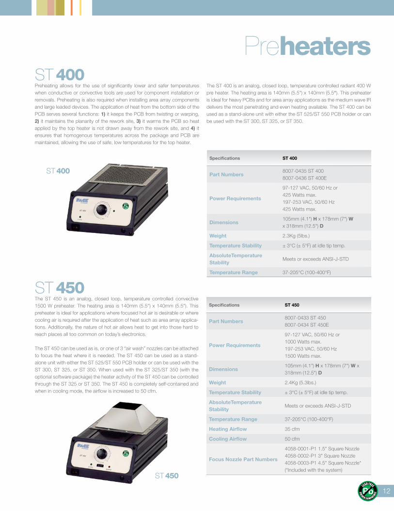
ST 450
PreheatersST 400Preheating allows for the use of significantly lower and safer temperatures when conductive or convective tools are used for component installation or removals. Preheating is also required when installing area array components and large leaded devices. The application of heat from the bottom side of the PCB serves several functions: 1) it keeps the PCB from twisting or warping, 2) it maintains the planarity of the rework site, 3) it warms the PCB so heat applied by the top heater is not drawn away from the rework site, and 4) it ensures that homogenous temperatures across the package and PCB are maintained, allowing the use of safe, low temperatures for the top heater.
The ST 400 is an analog, closed loop, temperature controlled radiant 400 W pre heater. The heating area is 140mm (5.5") x 140mm (5.5"). This preheater is ideal for heavy PCBs and for area array applications as the medium wave IR delivers the most penetrating and even heating available. The ST 400 can be used as a stand-alone unit with either the ST 525/ST 550 PCB holder or can be used with the ST 300, ST 325, or ST 350.
ST 450The ST 450 is an analog, closed loop, temperature controlled convective 1500 W preheater. The heating area is 140mm (5.5") x 140mm (5.5"). This preheater is ideal for applications where focused hot air is desirable or where cooling air is required after the application of heat such as area array applica-tions. Additionally, the nature of hot air allows heat to get into those hard to reach places all too common on today’s electronics. The ST 450 can be used as is, or one of 3 “air wash” nozzles can be attached to focus the heat where it is needed. The ST 450 can be used as a stand-alone unit with either the ST 525/ST 550 PCB holder or can be used with the ST 300, ST 325, or ST 350. When used with the ST 325/ST 350 (with the optional software package) the heater activity of the ST 450 can be controlled through the ST 325 or ST 350. The ST 450 is completely self-contained and when in cooling mode, the airflow is increased to 50 cfm.
ST 400
Specifications ST 400
Part Numbers8007-0435 ST 4008007-0436 ST 400E
Power Requirements
97-127 VAC, 50/60 Hz or 425 Watts max.197-253 VAC, 50/60 Hz 425 Watts max.
Dimensions105mm (4.1") H x 178mm (7") W x 318mm (12.5") D
Weight 2.3Kg (5lbs.)
Temperature Stability ± 3°C (± 5°F) at idle tip temp.
AbsoluteTemperature Stability
Meets or exceeds ANSI-J-STD
Temperature Range 37-205°C (100-400°F)
Specifications ST 450
Part Numbers8007-0433 ST 4508007-0434 ST 450E
Power Requirements
97-127 VAC, 50/60 Hz or 1000 Watts max.197-253 VAC, 50/60 Hz 1500 Watts max.
Dimensions105mm (4.1") H x 178mm (7") W x 318mm (12.5") D
Weight 2.4Kg (5.3lbs.)
Temperature Stability ± 3°C (± 5°F) at idle tip temp.
AbsoluteTemperature Stability
Meets or exceeds ANSI-J-STD
Temperature Range 37-205°C (100-400°F)
Heating Airflow 35 cfm
Cooling Airflow 50 cfm
Focus Nozzle Part Numbers
4058-0001-P1 1.5" Square Nozzle4058-0002-P1 3" Square Nozzle4058-0003-P1 4.5" Square Nozzle* (*Included with the system)
13
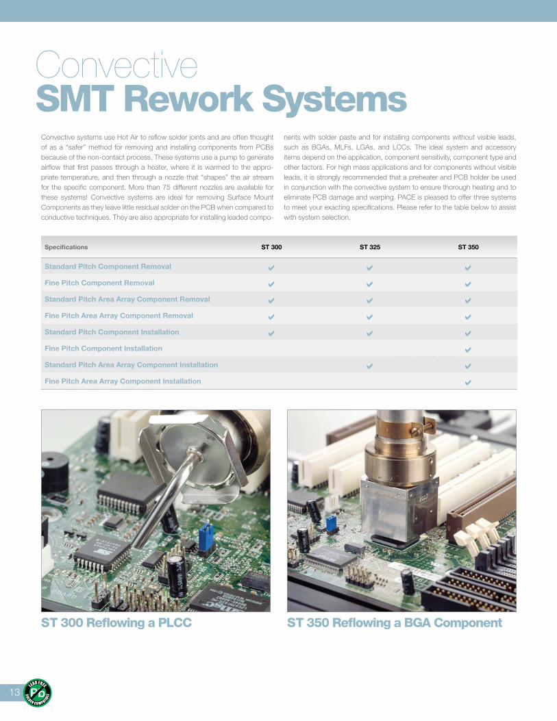
ConvectiveSMT Rework Systems
Convective systems use Hot Air to reflow solder joints and are often thought of as a “safer” method for removing and installing components from PCBs because of the non-contact process. These systems use a pump to generate airflow that first passes through a heater, where it is warmed to the appro-priate temperature, and then through a nozzle that “shapes” the air stream for the specific component. More than 75 different nozzles are available for these systems! Convective systems are ideal for removing Surface Mount Components as they leave little residual solder on the PCB when compared to conductive techniques. They are also appropriate for installing leaded compo-
nents with solder paste and for installing components without visible leads, such as BGAs, MLFs, LGAs, and LCCs. The ideal system and accessory items depend on the application, component sensitivity, component type and other factors. For high mass applications and for components without visible leads, it is strongly recommended that a preheater and PCB holder be used in conjunction with the convective system to ensure thorough heating and to eliminate PCB damage and warping. PACE is pleased to offer three systems to meet your exacting specifications. Please refer to the table below to assist with system selection.
ST 300 Reflowing a PLCC ST 350 Reflowing a BGA Component
XR 3000
Specifications ST 300 ST 325 ST 350
Standard Pitch Component Removal Fine Pitch Component Removal Standard Pitch Area Array Component Removal Fine Pitch Area Array Component Removal Standard Pitch Component Installation Fine Pitch Component Installation Standard Pitch Area Array Component Installation Fine Pitch Area Array Component Installation
14
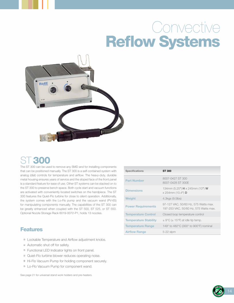
ConvectiveReflow Systems
ST 300The ST 300 can be used to remove any SMD and for installing components that can be positioned manually. The ST 300 is a self-contained system with analog (dial) controls for temperature and airflow. The heavy-duty, durable metal housing ensures years of service and the sloped face of the front panel is a standard feature for ease of use. Other ST systems can be stacked on to the ST 300 to preserve bench space. Both cycle start and vacuum functions are activated with conveniently located switches on the handpiece. The ST 300 features the Quiet-Flo turbine for close to silent operation. Additionally, the system comes with the Lo-Flo pump and the vacuum wand (PV-65) for manipulating components manually. The capabilities of the ST 300 can be greatly enhanced when coupled with the ST 500, ST 525, or ST 550. Optional Nozzle Storage Rack 6019-0072-P1, holds 13 nozzles.
Features
• Lockable Temperature and Airflow adjustment knobs.
• Automatic shut off for safety.
• Functional LED Indicator lights on front panel.
• Quiet-Flo turbine blower reduces operating noise.
• Hi-Flo Vacuum Pump for holding component securely.
• Lo-Flo Vacuum Pump for component wand.
See page 21 for universal stand work holders and pre-heaters.
Specifications ST 300
Part Number8007-0427 ST 3008007-0428 ST 300E
Dimensions134mm (5.25") H x 245mm (10") W x 254mm (10.4") D
Weight 4.3kgs (9.5lbs)
Power Requirements97-127 VAC, 50/60 Hz, 575 Watts max.197-253 VAC, 50/60 Hz, 575 Watts max.
Temperature Control Closed loop temperature control
Temperature Stability ± 9°C (± 15°F) at idle tip temp.
Temperature Range 149° to 482°C (300° to 900°F) nominal
Airflow Range 5-22 slpm
15
ConvectiveRework Systems
ST 325Front Panel
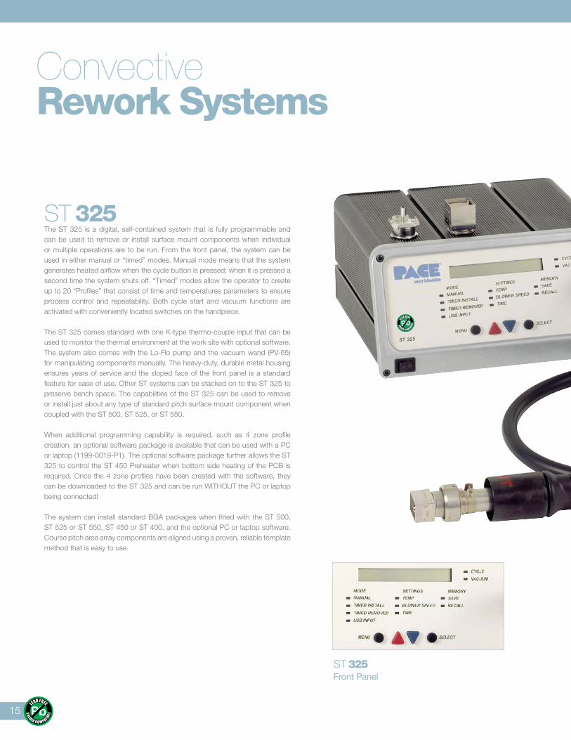
ST 325 The ST 325 is a digital, self-contained system that is fully programmable and can be used to remove or install surface mount components when individual or multiple operations are to be run. From the front panel, the system can be used in either manual or “timed” modes. Manual mode means that the system generates heated airflow when the cycle button is pressed; when it is pressed a second time the system shuts off. “Timed” modes allow the operator to create up to 20 “Profiles” that consist of time and temperatures parameters to ensure process control and repeatability. Both cycle start and vacuum functions are activated with conveniently located switches on the handpiece.
The ST 325 comes standard with one K-type thermo-couple input that can be used to monitor the thermal environment at the work site with optional software. The system also comes with the Lo-Flo pump and the vacuum wand (PV-65) for manipulating components manually. The heavy-duty, durable metal housing ensures years of service and the sloped face of the front panel is a standard feature for ease of use. Other ST systems can be stacked on to the ST 325 to preserve bench space. The capabilities of the ST 325 can be used to remove or install just about any type of standard pitch surface mount component when coupled with the ST 500, ST 525, or ST 550.
When additional programming capability is required, such as 4 zone profile creation, an optional software package is available that can be used with a PC or laptop (1199-0019-P1). The optional software package further allows the ST 325 to control the ST 450 Preheater when bottom side heating of the PCB is required. Once the 4 zone profiles have been created with the software, they can be downloaded to the ST 325 and can be run WITHOUT the PC or laptop being connected!
The system can install standard BGA packages when fitted with the ST 500, ST 525 or ST 550, ST 450 or ST 400, and the optional PC or laptop software. Course pitch area array components are aligned using a proven, reliable template method that is easy to use.
16
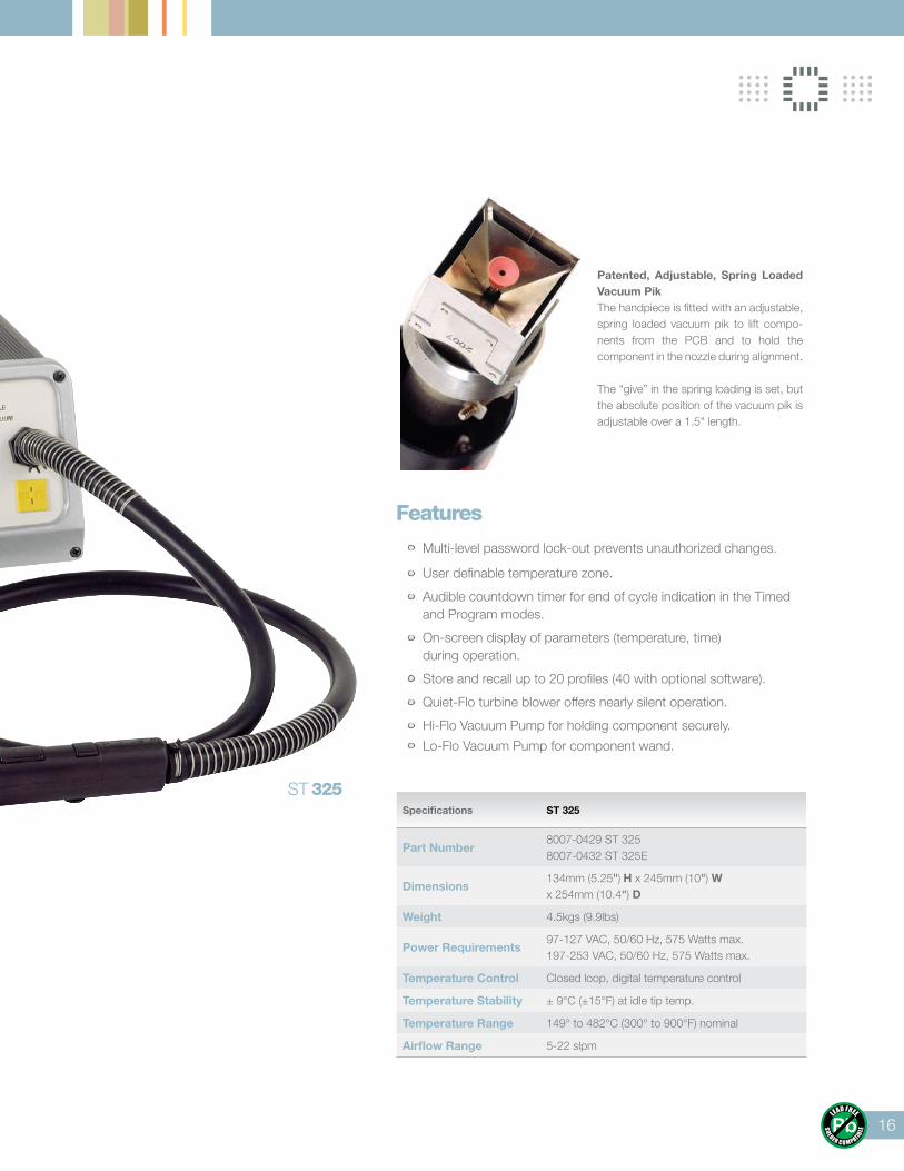
Patented, Adjustable, Spring Loaded Vacuum PikThe handpiece is fitted with an adjustable, spring loaded vacuum pik to lift compo-nents from the PCB and to hold the component in the nozzle during alignment.
The “give” in the spring loading is set, but the absolute position of the vacuum pik is adjustable over a 1.5" length.
Features
• Multi-level password lock-out prevents unauthorized changes.
• User definable temperature zone.
• Audible countdown timer for end of cycle indication in the Timed and Program modes.
• On-screen display of parameters (temperature, time) during operation.
• Store and recall up to 20 profiles (40 with optional software).
• Quiet-Flo turbine blower offers nearly silent operation.
• Hi-Flo Vacuum Pump for holding component securely.
• Lo-Flo Vacuum Pump for component wand.
Specifications ST 325
Part Number8007-0429 ST 3258007-0432 ST 325E
Dimensions134mm (5.25") H x 245mm (10") W x 254mm (10.4") D
Weight 4.5kgs (9.9lbs)
Power Requirements97-127 VAC, 50/60 Hz, 575 Watts max.197-253 VAC, 50/60 Hz, 575 Watts max.
Temperature Control Closed loop, digital temperature control
Temperature Stability ± 9°C (±15°F) at idle tip temp.
Temperature Range 149° to 482°C (300° to 900°F) nominal
Airflow Range 5-22 slpm
ST 325
17
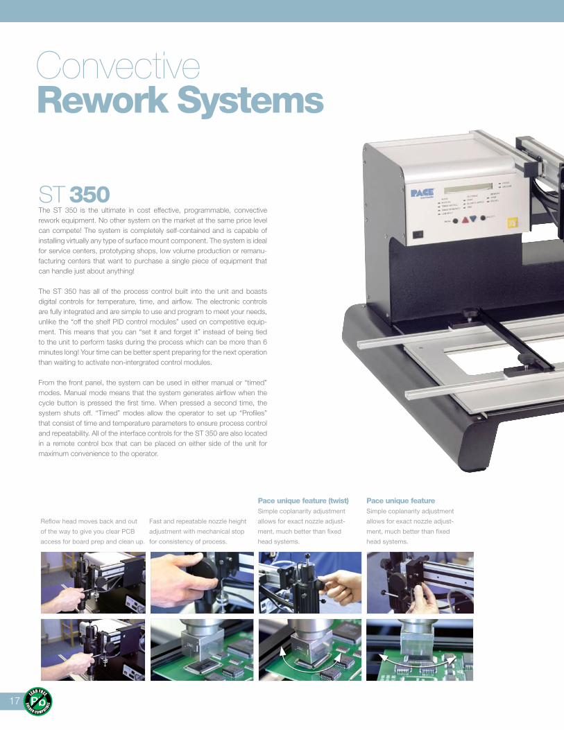
Reflow head moves back and out
of the way to give you clear PCB
access for board prep and clean up.
Fast and repeatable nozzle height
adjustment with mechanical stop
for consistency of process.
Pace unique feature (twist)Simple coplanarity adjustment
allows for exact nozzle adjust-
ment, much better than fixed
head systems.
Pace unique featureSimple coplanarity adjustment
allows for exact nozzle adjust-
ment, much better than fixed
head systems.
ST 350The ST 350 is the ultimate in cost effective, programmable, convective rework equipment. No other system on the market at the same price level can compete! The system is completely self-contained and is capable of installing virtually any type of surface mount component. The system is ideal for service centers, prototyping shops, low volume production or remanu-facturing centers that want to purchase a single piece of equipment that can handle just about anything!
The ST 350 has all of the process control built into the unit and boasts digital controls for temperature, time, and airflow. The electronic controls are fully integrated and are simple to use and program to meet your needs, unlike the “off the shelf PID control modules” used on competitive equip-ment. This means that you can “set it and forget it” instead of being tied to the unit to perform tasks during the process which can be more than 6 minutes long! Your time can be better spent preparing for the next operation than waiting to activate non-intergrated control modules.
From the front panel, the system can be used in either manual or “timed” modes. Manual mode means that the system generates airflow when the cycle button is pressed the first time. When pressed a second time, the system shuts off. “Timed” modes allow the operator to set up “Profiles” that consist of time and temperature parameters to ensure process control and repeatability. All of the interface controls for the ST 350 are also located in a remote control box that can be placed on either side of the unit for maximum convenience to the operator.
ConvectiveRework Systems
18
Specifications ST 350
Part Numbers8007-0437 ST 3508007-0438 ST 350E
Power Requirements97-127 VAC, 50/60 Hz, 575 Watts max.197-253 VAC, 50/60 Hz, 575 Watts max.
Dimensions578mm (22.75") H x 930mm (36.75") Wx 665mm (26.25") D
Weight 26.4Kg (58lbs.)
Temperature Control Closed loop, digital temperature control
Temperature Stability ± 9°C (±15°F) at idle tip temp.
Temperature Range 149° to 482°C (300° to 900°F) nominal
Airflow Range 5-22 slpm
Features • Multi-level password lock-out prevents unauthorized changes.
• User definable temperature zone.
• Audible countdown timer for end of cycle indication in the Timed and Program modes.
• Store and recall up to 20 profiles (40 with optional software).
• Quiet-Flo turbine blower offers nearly silent operation.
• On-screen display of parameters (temperature, time) during operation.
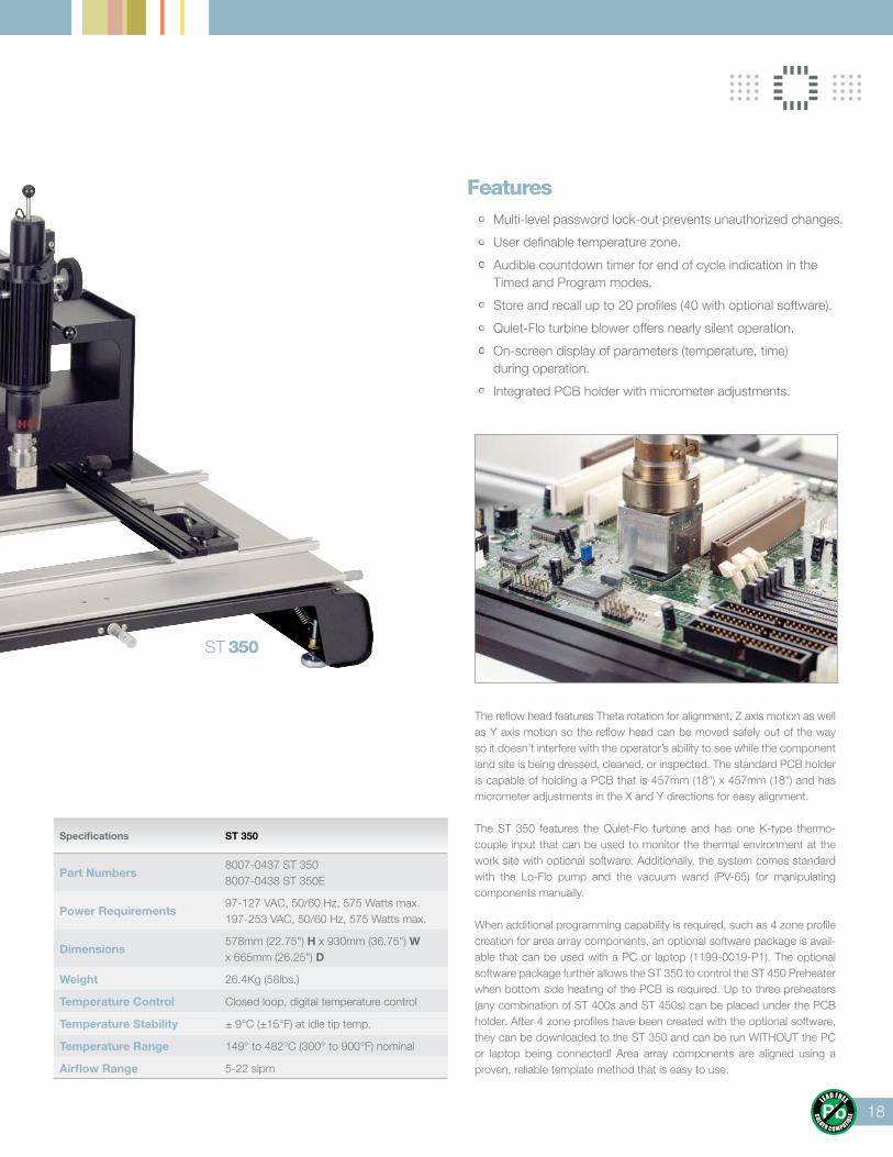
• Integrated PCB holder with micrometer adjustments.
The reflow head features Theta rotation for alignment, Z axis motion as well as Y axis motion so the reflow head can be moved safely out of the way so it doesn’t interfere with the operator’s ability to see while the component land site is being dressed, cleaned, or inspected. The standard PCB holder is capable of holding a PCB that is 457mm (18") x 457mm (18") and has micrometer adjustments in the X and Y directions for easy alignment.
The ST 350 features the Quiet-Flo turbine and has one K-type thermo-couple input that can be used to monitor the thermal environment at the work site with optional software. Additionally, the system comes standard with the Lo-Flo pump and the vacuum wand (PV-65) for manipulating components manually.
When additional programming capability is required, such as 4 zone profile creation for area array components, an optional software package is avail-able that can be used with a PC or laptop (1199-0019-P1). The optional software package further allows the ST 350 to control the ST 450 Preheater when bottom side heating of the PCB is required. Up to three preheaters (any combination of ST 400s and ST 450s) can be placed under the PCB holder. After 4 zone profiles have been created with the optional software, they can be downloaded to the ST 350 and can be run WITHOUT the PC or laptop being connected! Area array components are aligned using a proven, reliable template method that is easy to use.
ST 350
19
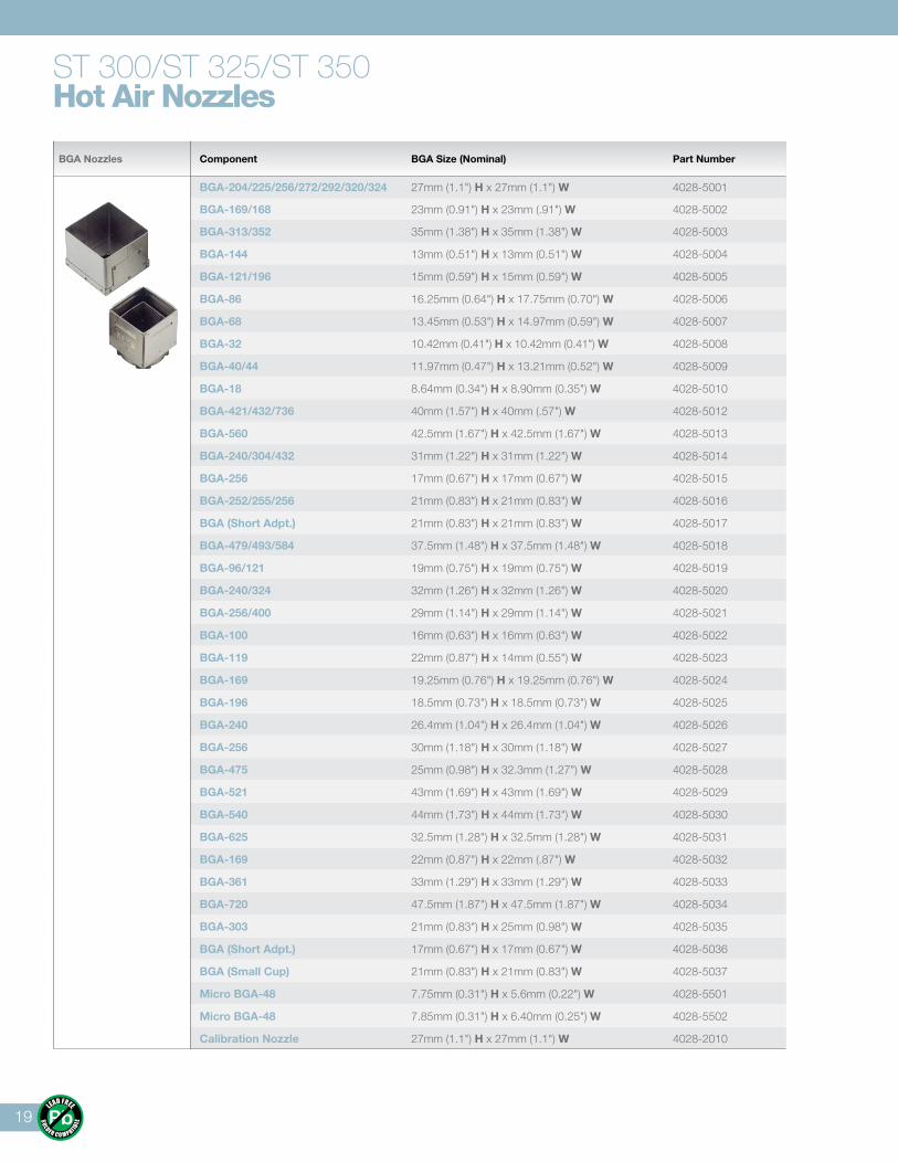
BGA Nozzles Component BGA Size (Nominal) Part Number
BGA-204/225/256/272/292/320/324 27mm (1.1") H x 27mm (1.1") W 4028-5001
BGA-169/168 23mm (0.91") H x 23mm (.91") W 4028-5002
BGA-313/352 35mm (1.38") H x 35mm (1.38") W 4028-5003
BGA-144 13mm (0.51") H x 13mm (0.51") W 4028-5004
BGA-121/196 15mm (0.59") H x 15mm (0.59") W 4028-5005
BGA-86 16.25mm (0.64") H x 17.75mm (0.70") W 4028-5006
BGA-68 13.45mm (0.53") H x 14.97mm (0.59") W 4028-5007
BGA-32 10.42mm (0.41") H x 10.42mm (0.41") W 4028-5008
BGA-40/44 11.97mm (0.47") H x 13.21mm (0.52") W 4028-5009
BGA-18 8.64mm (0.34") H x 8.90mm (0.35") W 4028-5010
BGA-421/432/736 40mm (1.57") H x 40mm (.57") W 4028-5012
BGA-560 42.5mm (1.67") H x 42.5mm (1.67") W 4028-5013
BGA-240/304/432 31mm (1.22") H x 31mm (1.22") W 4028-5014
BGA-256 17mm (0.67") H x 17mm (0.67") W 4028-5015
BGA-252/255/256 21mm (0.83") H x 21mm (0.83") W 4028-5016
BGA (Short Adpt.) 21mm (0.83") H x 21mm (0.83") W 4028-5017
BGA-479/493/584 37.5mm (1.48") H x 37.5mm (1.48") W 4028-5018
BGA-96/121 19mm (0.75") H x 19mm (0.75") W 4028-5019
BGA-240/324 32mm (1.26") H x 32mm (1.26") W 4028-5020
BGA-256/400 29mm (1.14") H x 29mm (1.14") W 4028-5021
BGA-100 16mm (0.63") H x 16mm (0.63") W 4028-5022
BGA-119 22mm (0.87") H x 14mm (0.55") W 4028-5023
BGA-169 19.25mm (0.76") H x 19.25mm (0.76") W 4028-5024
BGA-196 18.5mm (0.73") H x 18.5mm (0.73") W 4028-5025
BGA-240 26.4mm (1.04") H x 26.4mm (1.04") W 4028-5026
BGA-256 30mm (1.18") H x 30mm (1.18") W 4028-5027
BGA-475 25mm (0.98") H x 32.3mm (1.27") W 4028-5028
BGA-521 43mm (1.69") H x 43mm (1.69") W 4028-5029
BGA-540 44mm (1.73") H x 44mm (1.73") W 4028-5030
BGA-625 32.5mm (1.28") H x 32.5mm (1.28") W 4028-5031
BGA-169 22mm (0.87") H x 22mm (.87") W 4028-5032
BGA-361 33mm (1.29") H x 33mm (1.29") W 4028-5033
BGA-720 47.5mm (1.87") H x 47.5mm (1.87") W 4028-5034
BGA-303 21mm (0.83") H x 25mm (0.98") W 4028-5035
BGA (Short Adpt.) 17mm (0.67") H x 17mm (0.67") W 4028-5036
BGA (Small Cup) 21mm (0.83") H x 21mm (0.83") W 4028-5037
Micro BGA-48 7.75mm (0.31") H x 5.6mm (0.22") W 4028-5501
Micro BGA-48 7.85mm (0.31") H x 6.40mm (0.25") W 4028-5502
Calibration Nozzle 27mm (1.1") H x 27mm (1.1") W 4028-2010
ST 300/ST 325/ST 350Hot Air Nozzles
20
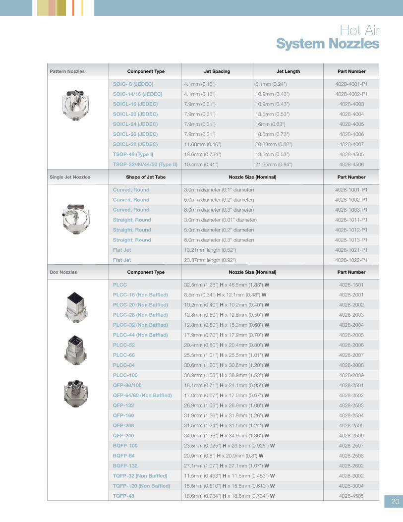
Box Nozzles Component Type Nozzle Size (Nominal) Part Number
PLCC 32.5mm (1.28") H x 46.5mm (1.83") W 4028-1501
PLCC-18 (Non Baffled) 8.5mm (0.34") H x 12.1mm (0.48") W 4028-2001
PLCC-20 (Non Baffled) 10.2mm (0.40") H x 10.2mm (0.40") W 4028-2002
PLCC-28 (Non Baffled) 12.8mm (0.50") H x 12.8mm (0.50") W 4028-2003
PLCC-32 (Non Baffled) 12.8mm (0.50") H x 15.3mm (0.60") W 4028-2004
PLCC-44 (Non Baffled) 17.9mm (0.70") H x 17.9mm (0.70") W 4028-2005
PLCC-52 20.4mm (0.80") H x 20.4mm (0.80") W 4028-2006
PLCC-68 25.5mm (1.01") H x 25.5mm (1.01") W 4028-2007
PLCC-84 30.6mm (1.20") H x 30.6mm (1.20") W 4028-2008
PLCC-100 38.9mm (1.53") H x 38.9mm (1.53") W 4028-2009
QFP-80/100 18.1mm (0.71") H x 24.1mm (0.95") W 4028-2501
QFP-64/80 (Non Baffled) 17.0mm (0.67") H x 17.0mm (0.67") W 4028-2502
QFP-132 26.9mm (1.06") H x 26.9mm (1.06") W 4028-2503
QFP-160 31.9mm (1.26") H x 31.9mm (1.26") W 4028-2504
QFP-208 31.5mm (1.24") H x 31.5mm (1.24") W 4028-2505
QFP-240 34.6mm (1.36") H x 34.6mm (1.36") W 4028-2506
BQFP-100 23.5mm (0.925") H x 23.5mm (0.925") W 4028-2507
BQFP-84 20.9mm (0.8") H x 20.9mm (0.8") W 4028-2508
BQFP-132 27.1mm (1.07") H x 27.1mm (1.07") W 4028-2602
TQFP-32 (Non Baffled) 11.5mm (0.453") H x 11.5mm (0.453") W 4028-3002
TQFP-120 (Non Baffled) 15.5mm (0.610") H x 15.5mm (0.610") W 4028-3004
TQFP-48 18.6mm (0.734") H x 18.6mm (0.734") W 4028-4505
Hot AirSystem Nozzles
Pattern Nozzles Component Type Jet Spacing Jet Length Part Number
SOIC- 8 (JEDEC) 4.1mm (0.16") 6.1mm (0.24") 4028-4001-P1
SOIC-14/16 (JEDEC) 4.1mm (0.16") 10.9mm (0.43") 4028-4002-P1
SOICL-16 (JEDEC) 7.9mm (0.31") 10.9mm (0.43") 4028-4003
SOICL-20 (JEDEC) 7.9mm (0.31") 13.5mm (0.53") 4028-4004
SOICL-24 (JEDEC) 7.9mm (0.31") 16mm (0.63") 4028-4005
SOICL-28 (JEDEC) 7.9mm (0.31") 18.5mm (0.73") 4028-4006
SOICL-32 (JEDEC) 11.68mm (0.46") 20.83mm (0.82") 4028-4007
TSOP-48 (Type I) 18.6mm (0.734") 13.5mm (0.53") 4028-4505
TSOP-32/40/44/50 (Type II) 10.4mm (0.41") 21.35mm (0.84") 4028-4506
Single Jet Nozzles Shape of Jet Tube Nozzle Size (Nominal) Part Number
Curved, Round 3.0mm diameter (0.1" diameter) 4028-1001-P1
Curved, Round 5.0mm diameter (0.2" diameter) 4028-1002-P1
Curved, Round 8.0mm diameter (0.3" diameter) 4028-1003-P1
Straight, Round 3.0mm diameter (0.01" diameter) 4028-1011-P1
Straight, Round 5.0mm diameter (0.2" diameter) 4028-1012-P1
Straight, Round 8.0mm diameter (0.3" diameter) 4028-1013-P1
Flat Jet 13.21mm length (0.52") 4028-1021-P1
Flat Jet 23.37mm length (0.92") 4028-1022-P1
21
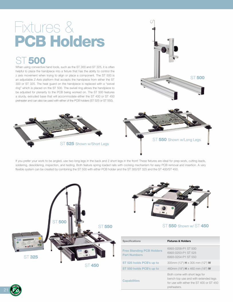
ST 500When using convective hand tools, such as the ST 300 and ST 325, it is often helpful to place the handpiece into a fixture that has the ability to control the z axis movement when trying to align or place a component. The ST 500 is an adjustable Z-Axis platform that accepts the handpiece from either the ST 300 or ST 325. The heat guard on the handpiece is replaced with a “swivel ring” which is placed on the ST 500. The swivel ring allows the handpiece to be adjusted for planarity to the PCB being worked on. The ST 500 features a sturdy, extruded base that will accommodate either the ST 400 or ST 450 preheater and can also be used with either of the PCB holders (ST 525 or ST 550).
ST 325
ST 550
ST 450
ST 500
ST 525 Shown w/Short Legs
Fixtures &PCB Holders
If you prefer your work to be angled, use two long legs in the back and 2 short legs in the front! These fixtures are ideal for prep-work, cutting leads, soldering, desoldering, inspection, and testing. Both feature spring loaded rails with cocking mechanism for easy PCB removal and insertion. A very flexible system can be created by combining the ST 500 with either PCB holder and the ST 300/ST 325 and the ST 400/ST 450.
Specifications Fixtures & Holders
Free Standing PCB HoldersPart Numbers
6993-0258-P1 ST 5006993-0253-P1 ST 5256993-0254-P1 ST 550
ST 525 holds PCB’s up to 305mm (12") H x 305 mm (12") W
ST 550 holds PCB’s up to 460mm (18") H x 460 mm (18") W
Capabilities
Both come with short legs for bench-top use and with extended legs for use with either the ST 400 or ST 450 preheaters.
ST 550 Shown w/Long Legs
ST 500
ST 550 Shown w/ ST 450
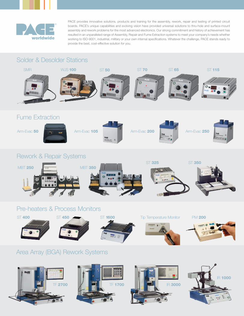
PACE provides innovative solutions, products and training for the assembly, rework, repair and testing of printed circuit boards. PACE’s unique capabilities and evolving vision have provided universal solutions to thru-hole and surface-mount assembly and rework problems for the most advanced electronics. Our strong commitment and history of achievement has resulted in an unparalleled range of Assembly, Repair and Fume Extraction systems to meet your company’s needs whether working to ISO-9001, industrial, military or your own internal specifications. Whatever the challenge, PACE stands ready to provide the best, cost-effective solution for you.
worldwide
ST 65 ST 115ST 50 ST 70WJS 100SMR
Arm-Evac 105
Solder & Desolder Stations
Arm-Evac 200Arm-Evac 50 Arm-Evac 250
Fume Extraction
ST 325 ST 350MBT 350MBT 250
Rework & Repair Systems
Pre-heaters & Process Monitors
Area Array (BGA) Rework Systems
TF 2700 TF 1700
IR 1000
IR 3000
ST 400 Tip Temperature MonitorST 450 ST 1600 PM 200

Solutions and systems for soldering, rework and repair of electronics
www.paceworldwide.com
PACE Worldwide255 Air Tool DriveSouthern Pines, NC 28387
phone 1.877.882.PACE fax 910.695.1594
PACE Europe Limited 11 Holdom AvenueBletchley, Milton Keynes, Buckinghamshire, MK1 1QU (UK)
phone +44 1908 277666 fax +44 1908 277777
P/N: 5400-0141 02/12
A Worldwide Commitment
With offices worldwide, PACE is a recognized world leader in the development of solutions for the assembly and repair of highly advanced electronics. Our expertise extends back to the dawn of the modern electronics industry. In 1958, PACE introduced training programs for the repair of printed wire assemblies and soon after, revolutionized the industry by creating the first self-contained vacuum desoldering system.
Today, PACE continues to provide innovative solutions, products and training for the rework, repair and testing of printed circuit assemblies. Our unique capabilities and evolving vision have provided universal solutions for thru-hole and surface mount assembly and rework problems for the most advanced electronics.
Additionally, PACE manufactures Fume Extraction Systems to reduce exposure to harmful particulates and gases created from hand soldering operations. PACE Fume Extraction Systems effectively remove these contaminants from the worker’s breathing zone thereby reducing or eliminating health risks and improving productivity.
Our strong commitment and history of achievement has resulted in an unparalleled range of Assembly, Repair and Fume Extraction solutions to meet your needs whether working to ISO-9001, industrial, military or your own internal specifications. Whatever the challenge, PACE stands ready to help you set a new standard.
The following are trademarks and/or service marks of PACE, Incorporated, Southern Pines, NC USA: Arm-Evac®, Cir-Kit®, ConducTweez™, Flo-D-Sodr®, HandiPik™, IntelliHeat®, LapFlo™, Mini-Wave®, MiniTweez®, PACE®, PACE EUROPE®, PACE WORLDWIDE®, PACENTER®, Pik-Tip®, PikVac™, Redi-Rak™, ResisTweez™, SensaTemp®, SMR™, Snap-Vac®, SodrTek®, Sodr-X-Tractor®, StripTweez™, Thermo-Drive®, ThermoFlo®, ThermoJet®, ThermoPik™, ThermoTweez®, and VisiFilter™. PACE products meet or exceed all applicable military or civilian EOS/ESD, temperature stability and other specifications, including MIL-STD-2000, ANSI/J-STD001, IPC 7711, IPC 7721 and IPC-A-610.