Embed Size (px)
Citation preview
. . , .:, . ..
'i I AEROIET 3 3 8 6
SNAP-8 PERFORMANCE POTENTIAL STUDY FINAL REPORT
p r e p a r e d f o r
N A T I O N A L A E R O N A U T I C S A N D S P A C E A D M I N I S T R A T I O N
L E W I S R E S E A R C H C E N T E R
C O N T R A C T N A S W 1 2 9 6
V O N K A R M A N C E N T E R
A L R O J E T - G E N E R A L C O R P O R A T I O N A Z U SA, C A L I FO RN I A
https://ntrs.nasa.gov/search.jsp?R=19670019843 2018-07-12T11:56:48+00:00Z
I 11
E 8 1
’ NASA C R 72254 A e r o j e t Rep&+ +O.Y 3386
-..’ I \ Fina l Repor t ;
. W A P - 8 PERFORMANCE POTENTIAL STUDY -
P r e p a r e d F o r
NATIONAL AERONAUTICS AND SPACE ADMINISTRATION
j April 1967 ’
> i )
4’ Contrac t NASW-1296 - P
I
TECHNICAL MANAGEMENT NASA LEWIS RESEARCH CENTER
CLEVELAND, OHIO
C . J . DAYE SNAP-8 PROJECT O F F I C E
* VON KARMAN CENTER,
Azusa, Cal i forn ia / AEROJE T -GENERAL CORPORATION
3,
Report No. 3386 1 I I d 8 1: This f i n a l report i s submitted i n p a r t i a l f u l f i l l m e n t of National Aerowut ics
and S p c e Administration Contract NASW-1296, and covers t h e period from 27 J u l y
1965 through 31 December 1966.
Approved :
Robert Gordon, Manager Power Systems Divis ion Von Karman Center
ii
I' I 3 0 I I 5 R 1 J I I
Report No. 3386
E 1
E I I 8 I 1
a
ABSTRACT*
The SNAP-8 Performance Potent ia l Study i s an evaluat ion of t h e performance
of t he developmental SNAP-8 e l e c t r i c a l generating system ( Z S ) .
the study i s t o assess t h e improvement i n o v e r a l l e f f ic iency , weight, r a d i a t o r
a rea , and power output t h a t can be rea l ized by s p e c i f i e d modifications of t he system
or i t s components. This report , t h e f i n a l repor t of t h e study, descr ibes t h e work performed and the r e s u l t s obtained.
compilation of the current SNAP-8 E S are presented and compared with similar
da ta f o r s i x improved systems incorporating var ious modifications.
The object ive of
The performance c h a r a c t e r i s t i c s and weight
The study a l s o included an inves t iga t ion of t h e SNAP-8 power system
i n t e g r a t e d with a direct-broadcast TV s a t e l l i t e vehic le i n synchronous o r b i t .
Final ly , a n assessment w a s made o f the p o t e n t i a l f o r increasing the operating
l i f e of t h e SNAP-8 system from 10,000 t o 20,000 hours.
s tud ie s a l s o a r e given i n the repor t .
The r e s u l t s of these
* NASA STAR Category 03.
iii
Report No. 3386
CONTENTS
Abbreviations
Symbols
I.
11.
111.
I V .
v.
V I .
SUMMAHY
A.
B. Study Plan
C. Summary Results
D. Conclusions of the Study
INTRODUCTION
A . SNAP-^ and i t s Development
FUNDAMENTAL DATA APPLICABLE TO ALL SYSTEMS STUDIED
A . Basic Configuration
B. Reactor and Shie ld
C. Radiator
D, S t ruc tu ra l Concepts
E. System Performance Analysis
Objectives and Guidelines of t h e Performance Potent ia l Study
BASELINE SYSTEM - EGS-0
A .
B.
BASIS FOR PERFORMANCE IMPROVEMENT
Select ion of Operating Condition f o r Analysis
Performance and Weight of EGS-0
A. Imprwement i n Overall Eff ic iency
B. Weight Reduction
C. Component Modifjcations and Subs t i tu t ions
D. Improvement by System Modifications
PERFORMANCE O F IMPROVED SYSTEMS
A . EGS-1
E. EGS -2
Page
ix
x i
1
1 2
4 9
11
11
13
13 1 4 14 21
23
25
e5 26
29
29
31 31 50
59
59 60
1 1 3 3 8 1 3 1 1 8 1 1
i v
Report No. 3386
CONTENTS (cont . )
C . EGS-3 61 D. EGS-4 62
E . EGS-5 63 F. EGS-6 64
V I I . INTEGRATION OF THE SNAP-8 EGS WITH A TV SATELLITE: AN
ILLUSTRATIVE APPLICATION STUDY 66
A. Introduction 66 B. Vehicle Conceptual. Design 69 C . Subsystem Charac te r i s t ics 74 D. Power Increase and Redundancy a0
E. Po ten t i a l of SNAP-8 EGS f o r 20,000-Hour Operating Li fe 80
References R- 1
Table
Summary Description of Systems Studied
Comparative. Performance Summary
EGS Weight Summary
Assessment of 20,000-Hour Life-Limiting Components
Advanced Reactor Charac te r i s t ics
Summary of Vapor-Chamber Fin Radiator Design Data
HRL Radiator Design Parameters
HRL Radiator Weight Breakdown
L/C Radiator Design Parameters
L/C Radiator Weight Breakdown
PCS Component Weight Reduction Summary
Comparison of Energy Dis t r ibu t ion f o r 5800- and 4800-rpm
Parameters f o r Custom Designed N a K PMA's Summary of MPMA Parameters and P a r a s i t i c Losses
Comparison of Losses f o r Present SNAP-8 (200°C) and
NaK PMA's
High- Temperature ( 400" C ) Alternators
5 6 7 a 9 10
11
12
13 14
15
V
Report No. 3386
CONTENTS (cont . )
Mercury Boiler Modification Summary 16
Factor Correction 17 18
19
Control of TV S a t e l l i t e 20
S a t e l l i t e Vehicle 2 1
Capacitive Reactance (kvar ) f o r A l t e rna to r Load Power
Weight Summary - TV S a t e l l i t e Vehicle (pounds)
Summary of SNAP-8 Performance and Spec i f i ca t ion Data
Summary of Typical Data f o r S ta t ion Keeping/Attitude
Ef fec t of Power Increase and Redundancy on TV
SNAP-8 4-Loop System Schematic
SNAP-8 E l e c t r i c a l Generating System Configuration
Heat Rejection Loop Radiator Charac t e r i s t i c s
Lubricant-Coolant Radiator C h a r a c t e r i s t i c s
600-kwt SNAP-8 Reactor and Shield
Relat ive Location of Heat Rejection Loop and Lubricant-
Development of Radiator Tube Pa t t e rns
Tube-Fin Configuration
Fin Effectiveness h n c t i o n
Heat Rejection Loop Radiator Map
Vapor-Chamber Fin Configuration
Comparison Between Vapor-Chamber Fin and Bumper-Fin
Lubricant-Coolant Radiator Map f o r One- and Two-Pass Flow
Radiator Structure Elements
PCS S t r u c t u r a l and Component Arrangement
EGS-0 Summary Performance Chart
EGS-0 Performance With Reactor Outlet Temperature a t
Power Di s t r ibu t ion Diagram f o r EGS-0
Pressure Rise and Input Power vs Flow Rate
Coolant Loop Radiator s
C apab ilit i e s
Lower L i m i t
f o r 5800 RPM N a K PMA
v i
Figure
1
2
3 4 5
6 7 8
9 10
11
12
13 14 15 16
17 18
19
Report No. 3386
CONTENTS (cont . ) Figure
Pressure Rise and Input Power vs Flow Rate f o r
Input Power and Head Rise v s Flow Rate f o r N a K PMA's
4800 rpm NaK PMA 20
Custom Designed f o r Lower Loop Impedance 2 1
Mercury PMA Suction C h a r a c t e r i s t i c s 22
Mercury Pump on Turbine Shaft 23 Mercury Pump on Alternator Shaft 24
Flow Diagram of Mercury Loop Incorporating J e t Pumps 25 SNAP-8 Alternator Charac t e r i s t i c s 26
Comparison of Induction and Homopolar Alternators 27
SCR Speed-Control Schematic 28
SCR Speed-Control Envelope 29 Boiler Pressure S t a b i l i t y Charac t e r i s t i c s 30 Rat io of Primary NaK Flow Rate to.Mercury Flow Rate
E f f e c t of Vehicle Load Variat ion on Alternator Load
vs Turbine I n l e t Pressure
Power Factor
Speed Control Power Factor vs Vehicle Load
31
32
33 Turbine Aerodynamic Eff ic iency as a Function of I n l e t and
E x i t Pr e s s ur e s 34 System Charac te r i s t i c s as a Function a t Turbine I n l e t and
E f f e c t of NaK Radiator AT and Turbine E x i t Pressure on Ex i t Pres sure s 35
Radiator Area 36 EGS-1 Summary Performance Chart 37 EGS-2 Summary Performance Chart 38 EGS-3 Summary Performance Chart 39 EGS-4 Summary Performance Chart 40 EGS-5 Summarry Performance Chart 41 EGS-6 Summary Performance Chart 42
Diagram of TV S a t e l l i t e i n Synchronous Orbit 43
44 Saturn V Vehicle ( L e f t ) and Enlarged View of SNAP-8
'ITV- S a t e l l i t e Vehicle (Right)
Conceptual Design of SNAP-8 TV-Satellite Vehicle 45
v i i
Report NO. 3386
CONTENTS lcont . )
E l e c t r i c a l Power Dis t r ibu t ion
Power Conditioning System D i a g r a m
TV Subsystem Water Cooling C i rcu i t
A t t i t ude
APPENDIX
APPENDIX
APPENDIX
Control System D i a g r a m
A - METEOROID PROTECTION C R I T E R I A
B - ELECTRICAL GENERATING SYSTEM WEIGHTS
c - ANALYSIS PrnSSURF:
OF TURBINE EFFICIENCY AS AFFECTED BY RATIO AND NUMBER OF STAGES
v i i i
U I J
47 48 1 49 E
AA
AGC
A I
EGS
FRA
Hg HRL
KVA
KVAR
L iH
LCA
L/C Hg PMA
NaK NaK PMA
NPSH
NS
PC s PLR
PM
PMA
SCAN
sc SCR
TA
TAA
TRA VLB
VR
Report No. 3386
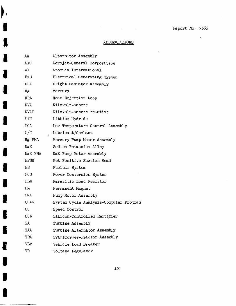
ABBREVI AT1 ONS
Al te rna tor Assembly
Aero j e t -General Corporation
Atomics In t e rna t iona l
E l e c t r i c a l Generating System
F l igh t Radiator Assembly
Mercury
Heat Rejection Loop
Rilovol t -ampere
Kilovolt-ampere r eac t ive
Lithium Hydride
Low Temperature Control Assembly
, Lubr i cant /Coolant
Mercury Pump Motor Assembly
Sodium-Potassium Alloy
NaK Pump Motor Assembly
Net Pos i t i ve Suction Head
NUC 1 ear System
Power Conversion System
P a r a s i t i c Load Resis tor
Permanent Magnet
Pump Motor Assembly
System Cycle Analysis-Computer Program
Speed Control
Sil icon-Controlled Rect i f ie r
Turbine Assembly Turbine Al te rna tor Assembly
Transformer-Reac t o r Assembly
Vehicle Load Breaker
Voltage Regulator
ix
Symbol
Y
TY
T2
n
W
C PL
d
tw ta
tf
Kw
KF
Dl a
6
€
h
U
PRECEDING PAGE BLANK NOT FILMED.
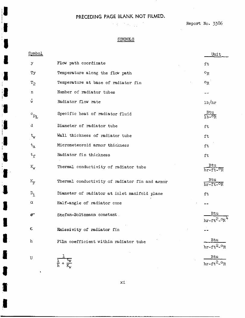
SYMBOLS
Flow pa th coordinate
Temperature along t h e flow path
Temperature a t base of r ad ia to r f i n
Number of r ad ia to r tubes
Radiator flow r a t e
Spec i f ic heat of r ad ia to r f l u i d
Diameter of r a d i a t o r tube
Wall thickness of r a d i a t o r tube
Micrometeoroid armor thickness
Radiator f i n thickness
Thermal conduct ivi ty of r ad ia to r tube
Thermal Conductivity of rad ia tor f i n and armor
Diameter of r ad ia to r a t i n l e t manifold plane
Half-angle of r a d i a t o r cone
Stefan-Boltzmann constan$
h i s s i v i t y of r ad ia to r f i n
Film c o e f f i c i e n t w i th in r ad ia to r tube
x i -
~~
Report No. 3386
Unit
f t
OR
OR
lb /hr
Btu m f t
f t
f t
f t
Btu h r - f t - O R
Btu hr- f t -OR
f t
Btu
h r - f t2 - %
Btu
h r - f t 2-0R
Btu
h r - f t2- OR
Symbol
h
UI
I
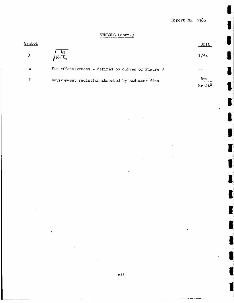
SYMBOLS ( c ont . )
Fin effectiveness - defined by curves of Figure 9
Environment r a d i a t i o n absorbed by r a d i a t o r f i n s
Report No. 3386 2 1
xii
Uni t I - l / f t
-- .I
Btu hr - f t2
I. SUMMARY
A study of t h e performance po ten t i a l of t h e SNAP-8 E l e c t r i c a l Generating
System (EGS) w a s performed by the Aerojet-General Corporation under cont rac t t o
the National Aeronautics and Space Administration (NASA).
s tudy was t o evaluate t h e performance t h a t can be a t t a i n e d by spec i f i ed system
and component modifications and t o compare t h e computed performance t o t h a t of
the development SNAP-8 power system as thus far demonstrated by t e s t . This
report , t he f i n a l r epor t of t he study, documents t h e work performed and t h e
r e s u l t s obtained.
The purpose of t h e
The SNAP-8 EGS i s a 35 kwe nuclear Rankine-cycle power system designed f o r
SNAP-8 has space appl ica t ions . Mercury is used a s t h e two-phase working f l u i d .
been under development s ince 1960 j o i n t l y sponsored by NASA and t h e Atomic Energy
Commission (AEC).
a continuous operat ing l i f e of 10,000 hours.
ments have been rev ised t o accommodate the needs of manned appl ica t ions as w e l l .
It w a s i n i t i a l l y designed f o r unmanned space missions and f o r
I n t h e pas t year i t s design require-
A. ONETIVES AND GTJIDELINES OFTHE PERFORMANCE POTENTIAL STUDY
Broadly, t h e object ives o f t h e s tudy are as fol lows:
1. To evaluate the performance improvement p o t e n t i a l of t h e
SNAP-8 EGS. weight, r a d i a t o r area, and power growth.
In t h i s context of t h e study, performance includes o v e r a l l e f f ic iency ,
2 . To inves t iga t e the in t eg ra t ion of t h e SNW-8 EGS i n an utimanned 7
f l i g h t vehic le . For t h i s purpose, a direct-broadcast TV s a t e l l i t e was chosen as
t h e mission model.
3 . To assess t h e po ten t i a l f o r increas ing the operat ing l i f e of
SNAP-8 from 10,000 t o 20,000 hours. -
1
I Summary, A (cont . ) Report No. 3386
In pursuing these objec t ives t h e following s tudy guide l ines were
es tab l i shed i n order t o maximize the u t i l i t y of t h e s tudy r e s u l t s .
I 1. The e x i s t i n g SNAP-8 four-loop system with organic- lubricated
b a l l bearings and low-temperature e l e c t r i c a l machinery was maintained.
SNAP-8 four-loop system is i l l u s t r a t e d i n a s impl i f i ed schematic diagram
(Figure 1).
The
0 2. The nominal maximum system temperature of 1300 F w a s used
throughout t h e study.
3 . Maximum reac to r output was kept a t 600 kw thermal, con-
s i s t e n t with ex i s t ing r eac to r design.
4. The power system configurat ion w a s based on t h e use of a
Saturn-class launch vehicle and an unmanned mission.
5 . Radiator p rope r t i e s were ca lcu la ted on t h e b a s i s of a 300
naut ical-mile o rb i t with maximum sun and e a r t h inc ident r a d i a t i o n and with t h e
recent meteoroid f lux and penet ra t ion da ta furnished by NASA, L e w i s Research
Center ( L~RC) .
a B. STUDY PLAN I
6 . Power system requirements such a s nuclear r ad ia t ion l e v e l s ,
output power cha rac t e r i s t i c s , and launch environmental s t r u c t u r a l loads conform
t o NASA SNAP-8 Specif icat ions, Series 417.
1. Baseline System
The f irst t a sk of t h e study was t h e cha rac t e r i za t ion of t h e
I 8
base l ine system, t h e e x i s t i n g developmental SNAP-8.
nated EGS-0) w a s defined by compiling ava i l ab le tes t da ta , supplementing t h i s
with d e t a i l e d design data , and then developing a r ep resen ta t ive f l i g h t configura-
t i o n of t h e complete power system.
The base l ine EGS* (desig-
a . The configurat ion 'was se l ec t ed f o r an unmanned low- o r b i t a l mission and on t h e b a s i s of compat ib i l i ty w i t h t h e Saturn s-IVB upper
* The term M;S designates t h e complete power system, inc luding t h e nuclear systems ( r eac to r and sh ie ld ) , t h e power conversion system (PCS), and t h e r a d i a t o r assembly-
2
I Swnmary, B (con t . ) Report No. 3386
s tage .
w a s adopted.
cen ter l i n e and the e l ec t ron ic payload loca ted adjacent t o t h e S-IVB mounting
plane. The configurat ion i s sketched i n Figure 2.
A conica l shape with a 9.75 degree cone half-angle and a 56-ft length
There i s a separa t ion dis tance of 50 f t between t h e r eac to r
b . Reactor and sh ie ld da ta were based on t h e e x i s t i n g
Atomics-International ( A I ) design, designated S8DS (Reference 1) The
s h i e l d s i z e w a s ad jus ted s o t h a t i t would conform t o t h e se l ec t ed configurat ion.
2. Improved Systems
Six improved SNAP-8 systems (designated EGS-1 through -6) were synthesized by means of a s teady-state ana lys i s and a d e t a i l e d weight
breakdown; the s i x improved systems incorporate var ious modifications from the
base l ine EGS, and are based on the configuration described above. In a l l
cases t h e r e were no changes i n t h e nominal maximum system temperature of 1300 F.
The purpose i n examining s i x d i f f e ren t systems w a s p a r t l y t o i s o l a t e t h e e f f e c t s
of t he var ious changes and p a r t l y t o develop in t e r im r e s u l t s before a l l of t h e
modifications were completely analyzed. The r e s u l t s of t h e first three improved
systems were reported i n the mid-term repor t of t h e s tudy (Reference 2 ) .
chief f ea tu re s of t h e improved systems a r e summarized i n Table 1.
3 e
0
The
Appli ca t ion Study_
A study of t h e in tegra t ion of t he SNAP-8 EGS with a d i r e c t -
broadcast TV s a t e l l i t e was conducted t o evaluate t h e e f f e c t of the mission on
t h e EGS and t h e e f f ec t of t he M;S on t h e mission, t o i d e n t i f y c r i t i c a l i n t e r -
faces and in t eg ra t ion problems, and t o develop a conceptual vehic le design and
genera l performance information. The EGS-4 power system w a s se lec ted f o r t h e
vehic le i n t eg ra t ion ana lys i s .
4. Assessment of 20,000-hour Life Po ten t i a l of SNAP-8
A b r i e f ana lys i s was made t o a s ses s the l i f e - l i m i t i n g components
of t h e SNAP-8 PCS; i . e . , i d e n t i f y po ten t i a l fa i lure modes and probable so lu t ions
requi red t o extend the operat ing l i f e of t he power system from 10,000 t o 20,000
hours.
3
I summary (cont. ) Report No. 3386
C. SUMMARY RESULTS
1. Performance Improvement
The major power system performance parameters a r e t abu la t ed
i n Table 2 f o r the base l ine system and the s i x improved systems.
i nd ica t e r e l a t i v e l y small incremental improvements i n each system compared t o
i t s immediate predecessor; however, when t h e change i n t h e la ter systems i s
compared t o t h e basel ine system, t h e improvement i n performance i s l a rge .
ove ra l l change i n performance may be seen from t h e following:
The da ta
The
M;s-0 ES-5 EGS-6 Baseline 40 kwe Max kwe
Overall Efficiency, 8 7.0 Weight, lb 11,000
1,433 Output Power, kwe 36
2 Radiator Area, f t
10.9 8,700
080 40
a. It i s of i n t e r e s t t o examine t h e f a c t o r s cont r ibu t ing
t o the improvement i n e f f i c i ency .
Rankine cycle e f f ic iency , t u rb ine e f f ic iency , a l t e r n a t o r e f f i c i ency , and para-
s i t i c eff ieciency" we f i n d t h a t t h e change i n o v e r a l l e f f i c i e n c y of 7$ t o 10.9% i s a t t r i b u t a b l e t o t he following changes i n t he subordinate e f f i c i e n c i e s .
Considering e f f i c i e n c y as t h e product of
M;s-0 E S - 5
Cycle e f f i c i ency .24 .26 Turbine e f f i c i ency .54 *59 Alternator e f f i c i ency .86 90
P a r a s i t i c e f f i c i ency .65 -79
Cycle e f f i c i ency i s increased by r a i s i n g tu rb ine i n l e t pressure from 240 t o 350 ps ia ; t u rb ine e f f i c i ency i s increased by t h e aero-
dynamic design improvements of t h e turb ine ; a l t e r n a t o r e f f i c i e n c y i s increased
by using capaci tors t o co r rec t t h e load power f a c t o r from .65 t o 1.0; p a r a s i t i c
* P a r a s i t i c e f f ic iency i s defined as t h e r a t i o of ne t power ava i l ab le t o t h e vehic le t o gross a l t e r n a t o r output power.
t I I s
8 a I 8
m
4
I Summary, c ( con t . ) Report No. 3386
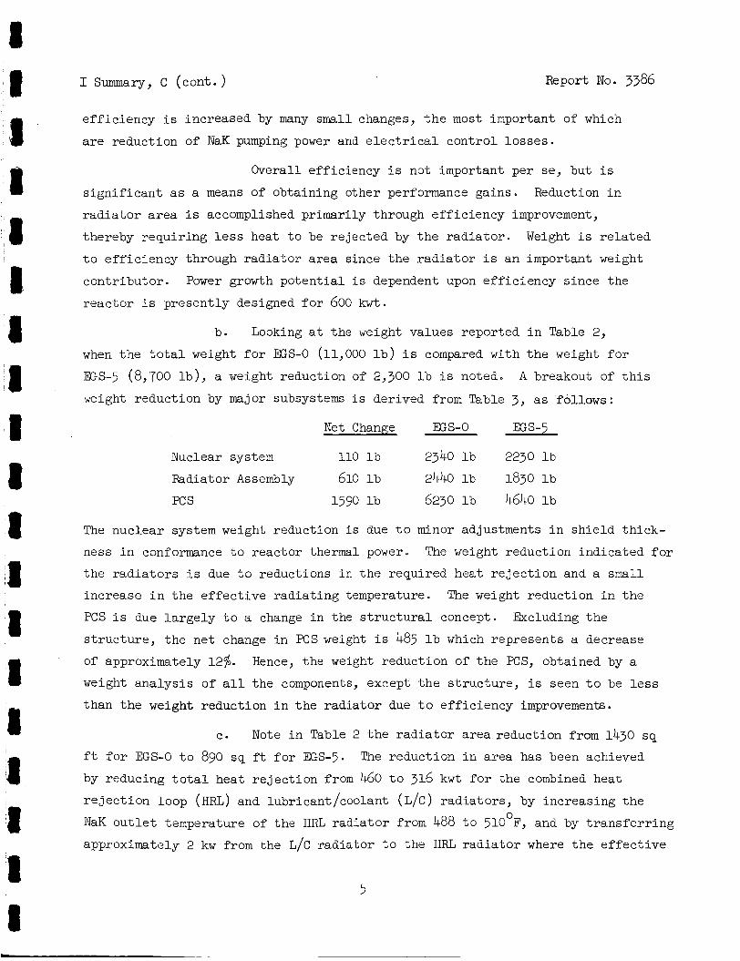
e f f i c i ency i s increased by many small changes, t h e most important of which
a r e reduct ion of NaK pumping power and e l e c t r i c a l con t ro l l o s s e s .
Overall e f f ic iency i s not important per se , but i s
s i g n i f i c a n t as a means of obtaining other performance gains .
r a d i a t o r a r e a i s accomplished pr imari ly through e f f i c i ency improvement,
thereby requi r ing less heat t o be r e j ec t ed by t h e r a d i a t o r . Weight i s r e l a t e d
t o e f f i c i ency through r a d i a t o r a rea since t h e r a d i a t o r i s an important weight
cont r ibu tor . Power growth p o t e n t i a l is dependent upon e f f i c i e n c y s ince the
r eac to r i s present ly designed f o r 600 kwt.
Reduction i n
b. Looking a t the weight values reported i n Table 2,
when t h e t o t a l weight f o r ES-0 (11,000 l b ) i s compared with t h e weight f o r
G S - 5 (8,700 l b ) , a weight reduction of 2,300 l b i s noted.
weight reduct ion by major subsystems i s derived from Table 3, a s fol lows:
A breakout of t h i s
Net Change EGS-0 E S - 5
Nuclear system 110 l b 2340 l b 2230 l b
Fkdiator Assembly 610 l b 2440 l b 1830 l b
PC s 1590 l b 6230 l b 4640 l b
The nuc lear system weight reduction i s due t o minor adjustments i n s h i e l d th i ck -
ness i n conformance t o r eac to r thermal power. The weight reduct ion ind ica ted f o r
t he r a d i a t o r s i s due t o reductions i n t h e required heat r e j e c t i o n and a small
increase i n t h e e f f e c t i v e r a d i a t i n g temperature. The weight reduct ion i n t h e
PCS i s due l a r g e l y t o a change i n the s t r u c t u r a l concept. Excluding t h e
s t ruc tu re , t h e ne t change i n PCS weight i s 485 l b which represents a decrease
of approximately 12%.
weight ana lys i s of a l l the components, except t h e s t r u c t u r e , i s seen t o be l e s s
than t h e weight reduction i n t h e r a d i a t o r due t o e f f i c i ency improvements.
Hence, the weight reduct ion of t h e PCS, obtained by a
e. Note i n Table 2 t h e r a d i a t o r a rea reduction from 1430 s q
f t f o r EGS-0 t o 890 sq f t f o r EGS-5.
by reducing t o t a l heat r e j e c t i o n from 460 t o 316 kwt f o r t h e combined heat
r e j e c t i o n loop (HRL) and lubricant /coolant (L/C) r ad ia to r s , by increas ing t h e
NaK o u t l e t temperature of t h e HRL r ad ia to r from 488 t o 510 F, and by t r a n s f e r r i n g
approximately 2 kw from the L/C r ad ia to r t o t he HRL r a d i a t o r where t h e e f f e c t i v e
The reduct ion i n a rea has been achieved
0
I I
5
I summary, c (cont. ) Report No. 3386
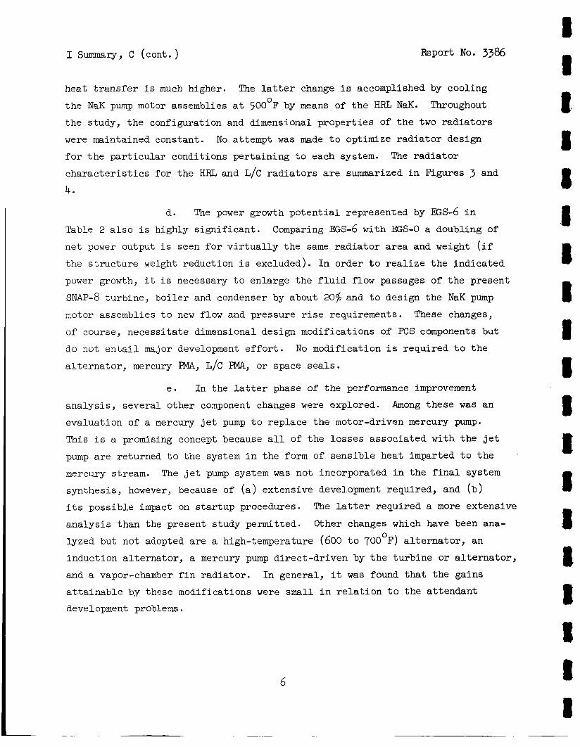
heat t r a n s f e r is much higher.
t h e NaK pump motor assemblies a t 500°F by means of t h e HRL NaK.
t h e study, t h e configuration and dimensional p rope r t i e s of t h e two r a d i a t o r s
were maintained constant.
f o r t h e p a r t i c u l a r condi t ions per ta in ing t o each system.
c h a r a c t e r i s t i c s for t he HRL and L/C r a d i a t o r s a r e summarized i n Figures 3 and
4.
The l a t t e r change is accomplished by cool ing
Throughout
No attempt was made t o optimize r a d i a t o r design
The r a d i a t o r
d. The power growth p o t e n t i a l represented by ES-6 i n
Table 2 a l s o i s highly s i g n i f i c a n t .
ne t power output i s seen f o r v i r t u a l l y t h e same r a d i a t o r a rea and weight ( i f
t h e s t r u c t u r e weight reduction i s excluded). In order t o r e a l i z e t h e ind ica t ed
power growth, it i s necessary t o enlarge t h e f l u i d flow passages of t h e present
SNAP-8 turb ine , b o i l e r and condenser by about 20% and t o design t h e NaK pump
motor assemblies t o new flow and pressure r i s e requirements. These changes,
of course, necess i t a t e dimensional design modif icat ions of PCS components but
do not e n t a i l major development e f f o r t .
a l t e r n a t o r , mercury EMA, L/C PMA, or space s e a l s .
Comparing EEs-6 with EES-0 a doubling of
No modification i s requi red t o t h e
e . I n the l a t t e r phase of t h e performance improvement
ana lys i s , severa l o ther component changes were explored.
evaluat ion of a mercury j e t pump t o replace t h e motor-driven mercury pump.
This i s a promising concept because a l l of t h e lo s ses assoc ia ted with t h e j e t
pump a r e returned t o t h e system i n t h e fo rm of s ens ib l e heat imparted t o t h e
mercury stream.
synthes is , however, because of (a) extensive development required, and ( b )
i t s poss ib le impact on s t a r t u p procedures.
ana lys i s than the present study permitted.
lyzed but not adopted a r e a high-temperature (600 t o TOO F) a l t e r n a t o r , an
induct ion a l t e r n a t o r , a mercury pump d i r ec t -d r iven by t h e tu rb ine or a l t e r n a t o r ,
and a vapor-chamber f i n r a d i a t o r . I n general , it w a s found that t h e gains
a t t a i n a b l e by these modifications were small i n r e l a t i o n t o t h e a t tendant
development problems.
Among these w a s an
'
The j e t pump system was not incorporated i n the f i n a l system
The la t ter requi red a more extensive
Other changes which have been ana- 0
8 I c I I I I I 8 I t t 8 4 8 I I I I
6
I summary, c (cont . ) Report No. 3386
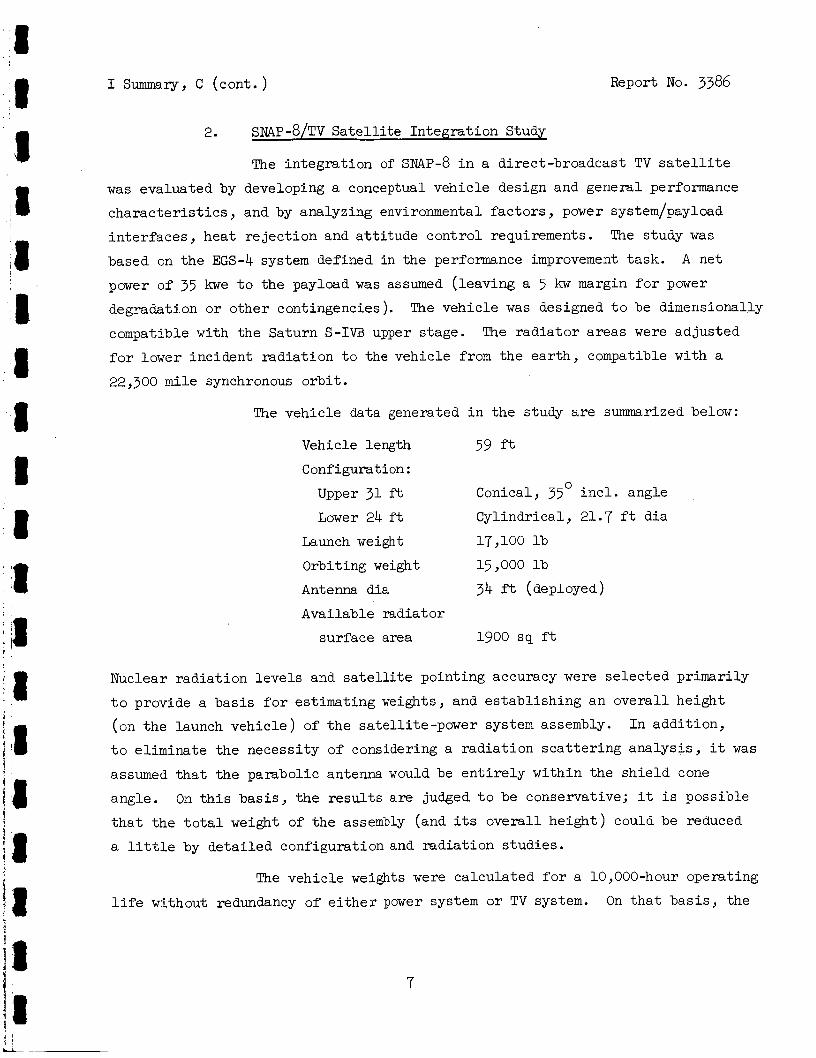
2. sMP-8/TV S a t e l l i t e In t eg ra t ion Study
The in t eg ra t ion of sMP-8 i n a direct-broadcast TV s a t e l l i t e
w a s evaluated by developing a conceptual vehic le design and general performance
c h a r a c t e r i s t i c s , and by analyzing environmental f a c t o r s , power system/payload
in t e r f aces , hea t r e j e c t i o n and a t t i t u d e con t ro l requirements.
based on t h e EGS-4 system defined i n t h e performance improvement t a sk .
power of 35 kwe t o the payload was assumed ( leaving a 5 kw margin f o r power
degradation o r o ther cont ingencies) .
compatible with t h e Saturn S-IVB upper s tage .
for lower inc ident r ad ia t ion t o the vehic le from t h e e a r t h , compatible with a
22,300 m i l e synchronous o r b i t .
The study w a s
A ne t
The vehic le was designed t o be dimensionally
The r a d i a t o r a r eas were ad jus ted
The vehic le data generated i n t h e study a r e summarized below:
Vehicle length 59 ft Configuration :
Upper 31 f t Conical, 35' i n c l . angle
Lower 24 f t C y l h d r i c a l , 21.7 f t d ia
Launch weight 17,100 l b
Orbiting weight 15,000 l b
Antenna dia 34 f t (deployed)
Avai lable rad ia tor
sur face area 1900 s q f t
Nuclear r ad ia t ion l e v e l s and s a t e l l i t e po in t ing accuracy were se l ec t ed pr imar i ly
t o provide a b a s i s f o r es t imat ing weights, and e s t ab l i sh ing an o v e r a l l he ight
(on t h e launch v e h i c l e ) of t h e sa te l l i t e -power system assembly. In add i t ion ,
t o eliminate t h e necess i ty of considering a r a d i a t i o n s c a t t e r i n g ana lys i s , it was
assumed t h a t t h e parabol ic antenna would be e n t i r e l y wi th in the s h i e l d cone
angle .
t h a t t h e t o t a l weight of t h e assembly (and i t s o v e r a l l h e i g h t ) could be reduced
a l i t t l e by d e t a i l e d configurat ion and r ad ia t ion s tud ie s .
On t h i s b a s i s , t h e r e s u l t s a r e judged t o be conservative; it i s poss ib le
The vehic le weights were ca l cu la t ed f o r a 10,000-hour operat ing
l i f e without redundancy of e i t h e r power system or TV system. On t h a t b a s i s , the
7
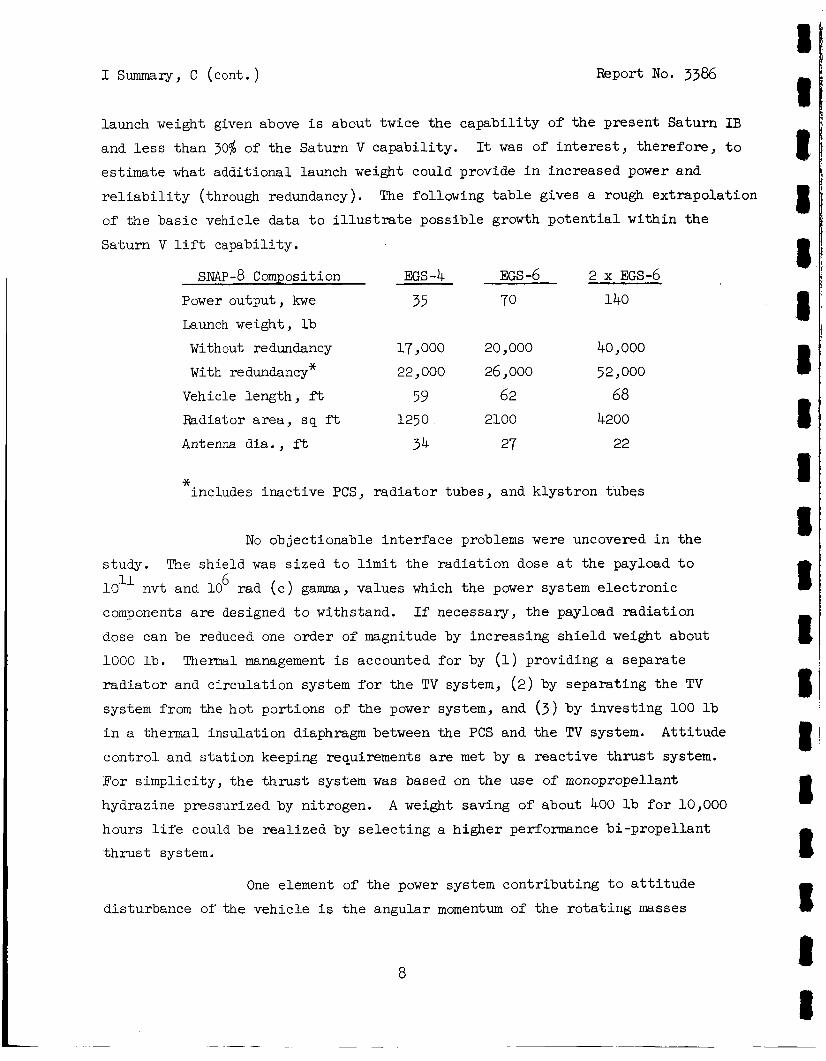
I summary, c (cont.) Report No. 3386
launch weight given above i s about twice the c a p a b i l i t y of t he present Saturn I B
and less than 30% of the Saturn V capabi l i ty . It was of in te res t , t h e r e f o r e , t o
es t imate what addi t ional launch weight could provide i n increased power and
r e l i a b i l i t y (through redundancy).
of the bas ic vehicle data t o i l l u s t r a t e poss ib le growth p o t e n t i a l within the
Saturn V l i f t capabi l i ty .
The following t a b l e gives a rough ex t rapola t ion
SNAP - 8 Composition EGS -4 EGS -6 2 x EGS-6 Power output , kwe 35 70 140
Launch weight, l b
Without redundancy 17,000 20 , 000 40,000
With redundancy* 22 J 000 26,000 52,000
Vehicle length, ft 59 62 68 Radiator a rea , sq f t 1250 2100 4200
Antenna dia . , ft 34 27 22
* includes inac t ive PCS, r a d i a t o r tubes, and k lys t ron tubes
No objectionable in t e r f ace problems were uncovered i n t h e
study. The sh ie ld was s i z e d t o l i m i t the r a d i a t i o n dose a t t he payload t o
10l1 nvt and 10
components are designed t o withstand.
dose can be reduced one order of magnitude by increasing s h i e l d weight about
1000 lb .
r a d i a t o r and c i rcu la t ion system f o r t he TV system, (2) by separa t ing the TV
system from the hot port ions of the power system, and ( 3 ) by inves t ing 100 l b
i n a thermal insu la t ion diaphragm between the PCS and the TV system.
cont ro l and s t a t i o n keeping requirements a r e m e t by a r e a c t i v e t h r u s t system.
For s impl i c i ty , t he t h r u s t system w a s based on the use of monopropellant
hydrazine pressurized by nitrogen.
hours l i f e could be r e a l i z e d by s e l e c t i n g a h ighe r performance bi-propel lant
t h r u s t sys tem.
6 rad ( c ) gamma, values which the power system e l e c t r o n i c
If necessary , t h e payload r a d i a t i o n
T h e m 1 management i s accounted f o r by (1) providing a separate
At t i tude
A weight saving of about 400 l b f o r 10,000
One element of t he power system cont r ibu t ing t o a t t i t u d e
disturbance of the vehicle i s t h e angular momentum of t'ne r o t a t i n g masses
8
I summary , c (cont. ) Report NO. 3386
(both s o l i d and l i q u i d ) i n the PCS.
l a r g e f a c t o r i n t o t a l a t t i t u d e control (it might requi re 100 lb of mono-
propel lan t f o r a 10,000 hour mission), bu t t h e study a l s o ind ica t ed t h a t t he
angular momentum of t h e power system could be i n t e r n a l l y balanced.
o r i en t ing a l l s o l i d r o t a t i n g components p a r a l l e l t o t h e major a x i s of t he
vehic le so t h a t t h e lesser components counteract t he l a r g e s t one ( the turb ine-
a l t e r n a t o r assembly) , and by f u r t h e r counteract ing the remaining unbalanced
momentum by t h e primary NaK piping, it was concluded t h a t a v i r t u a l balance
could be achieved by the addi t ion of about 30 f t of piping a t a weight pena l ty
of 60 l b .
Analysis ind ica ted t h a t t h i s i s not a
By
I n summary, no ser ious in t eg ra t ion or i n t e r f a c e problems
were found i n t h i s appl ica t ion study. However, it i s evident t h a t h igher power
and longer l i f e a r e important avenues f o r f u r t h e r evaluat ion.
3 . Assessment of 20,000-hour Li fe P o t e n t i a l of sWP-8
To assess the po ten t i a l f o r extended l i f e of t he s ~ p - 8 system,
t h e components of t h e PCS were examined t o i d e n t i f y , i f poss ib l e , those components
which a r e l i f e - l i m i t i n g .
major i ty of components, the present s tudy i s necessar i ly specula t ive and
q u a l i t a t i v e .
w a s made of t h e components judged most subjec t t o wear-out f a i l u r e i n less
than 20,000 hours.
Since f a i l u r e modes have not been i d e n t i f i e d f o r t he
With t h i s qua l i f i ca t ion , t he assessment summarized i n Table 4
Examination of the l i s t of f a i l u r e modes and probable so lu t ions
i n Table 4 on t h e b a s i s of present knowledge e s t ab l i shes t h a t t he re i s no evidence
t h a t components, e t c . , which have demonstrated 10,000 hours of l i f e cannot a t t a i n
20,000 hours l i f e , with or without some minor modification.
appear t h a t a severe penalty i n weight and performance must be pa id as the
p r i c e f o r a t t a i n i n g longer l i fe .
mode and mean-time-to-failure i s e s s e n t i a l t o a quan t i t a t ive assessment of
operat ing l i f e po ten t i a l .
Nei ther does it
However, t he i d e n t i f i c a t i o n of t r u e - f a i l u r e
D. CONCLUSIONS OF THE STUDY
The f indings of t he study l ead t o the following general conclusions:
9
I Summary, D ( con t . ) Report No. 3386
1. Large gains i n SNAP-8 system performance appear a t t a i n a b l e
without sweeping redesign of t he system or components and without advance i n
t h e s t a t e of the a r t .
( i n cos t and time) required t o e f f e c t redesign where ind ica ted and v e r i f y
through tes t programs.
No est imat ion has been made, however, of t h e e f f o r t
2.
s a t e l l i t e appears f eas ib l e .
payload and a l l i n t e g r a t i o n aspects s tud ied between t h e subsystems and t h e
launch vehic le appear suscept ib le t o s t r a i g h t forward engineering so lu t ions .
The s tudy ind ica tes , however, t h a t t he considerat ion of using a nuc lear power
system with such a s a t e l l i t e w i l l r equi re considerat ion of Saturn c l a s s boos te rs .
The in t eg ra t ion of t he SNAP-8 power system i n an unmanned TV
A l l i n t e r f aces between the power system and TV
3. The extension of sNAp-8 operat ing l i f e from 10,000 t o 20,000
No fundamental b a r r i e r s t o preclude at ta inment of t h e hours appears f eas ib l e .
longer l i f e were found, based on present ly-ava i lab le information. Moreover, it appears t h a t achievement of t he 20,000-hour l i f e need have only a small impact
on weight and performance.
10
8 I 8 8 8 8 I I 8 I I t I 1 8 8 8 I 8
Report No. 3386
11. INTRODUCTION
me SNAP-8 Performance Po ten t i a l Study serves an important func t ion ,
supplemental t o t h e SNAP-8 Development Program, i n providing a b a s i s f o r
p ro jec t ing the performance of t he system beyond t h e immediate development
l i m i t a t i o n s . I n eva lua t ing the competitive mer i t s of candidate power systems,
a t t a i n a b l e f l ight system performance becomes an important c r i t e r i a a performance
comparisons between a SNAP-8 EGS based on ground test developmental components
and a conpet i t ive power system Sased on paper designs of advanced technology
a r e not r e a l i s t i c . The i n t e n t of t h i s s tudy, t he re fo re , i s t o examine and
doe.ment a p ro jec t ion of SNAP-8 EGS performance t h a t i s t h e l o g i c a l extension
of t h e cur ren t development e f f o r t , and thereby provide a usefu l a i d t o mission
planners
A. S-NAP-8 AND ITS DEVELOPMENT
The SNAP-8 i s a t u rboe lec t r i c , nuclear , space power system using a
niercury Rankine cycle .
(1) a nuclear system cons is t ing of" a r eac to r , r eac to r con t ro l s , and sh ie ld ing;
( 2 ) a f l i g h t r a d i a t o r assembly cons is t ing of r a d i a t o r hea t exchangers requi red
t o remove hea t from t h e l i q u i d cooling loops; and ( 3 ) t h e PCS, cons i s t ing of
t u r b t n e - a l t e r n a t o r assembly (TAA)
a s sexb l i e s (PMA's ) and necessary controls p ip ing , and s t r u c t u r e . The sNAp-8 nuelear system i s being developed by Atomics I n t e r n a t i o n a l Divis ion of North
American Aviat ion, Inc. under contract t o the AEC. The PCS and the i n t e g r a t i o n
of t h e PCS with the nuclear system i s the r e s p o n s i b i l i t y of Aerojet-General
Corporation, Von Karman Center, under cont rac t t o NASA. Development of the
r a d i a t o r assembly i s not a p a r t of the cur ren t progran.
The system i s comprised of t h ree major subsystems:
b o i l e r , condenser, mercury and NaK pump-motor
The EGS i s designed. t o operate continuously f o r 10,000 hours i n
space a f t e r a remote automatic a t a r t zp .
system i s 35 kw.
The ne t e l e c t r r c a l output of t h e SNAP-8
Figure 1 shows schematically t h e func t iona l arrangement of t h e
four-loop SNAP-8 system.
hea t t o space, t h e r e a r e two d i s t i n c t r a d i a t i n g elements i n t h e flight r a d i a t o r
Since 'both t h e t h i r d and fou r th loops must r e j e c t
11
I1 Introduction, A ( con t . ) Report No. 3386
assembly.
temperatures i n t he range of 500 t o TOOOF. from t he organic l u b r i c a t i n g loop a t temperatures i n the range of 200 t o 250°F,
The f i r s t element r e j e c t s t he hea t from the NaK H a of t h e PCS a t The second element r e j e c t s hea t
The early development phase of SNAP-8, wherein t h e major components 8 s t a t u s of t he program. I were designed and t e s t e d , has been completed. Reference 3 describes t h e cur ren t
12
Report No. 3386
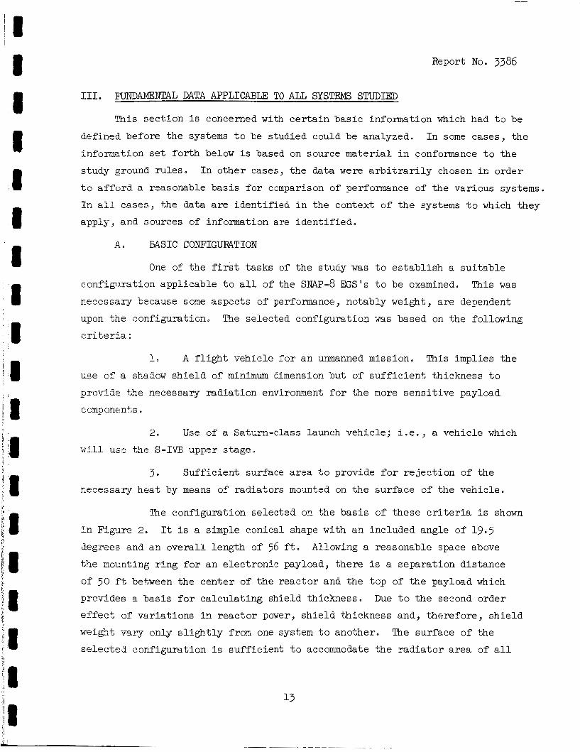
111. FUTDMNTAL DATA APPLICABLE TO ALL SYSTEMS STUDIED
This sec t ion i s concerned w i t h c e r t a i n bas i c information which had t o be
defined before the systems t o be s tudied could be analyzed. I n some cases , t h e
Pnformation set f o r t h below is based on source ma te r i a l i n conformance t o the
s tudy ground ru l e s . I n o the r cases, t he data were a r b i t r a r i l y chosen i n order
t o a f f o r d a reasonable b a s i s f o r comparison of performance of t he var ious systems.
I n a l l cases , t he data are iden t i f i ed i n the context of t h e systems t o which they
apply, and sources of information are i d e n t i f i e d .
A. BASIC CONFIGURATION
One of" t h e f i r s t t a sks of the study w a s t o e s t a b l i s h a s u i t a b l e
configurat ion appl icable t o a l l of the s ~ A p - 8 EGS's t o be examined.
necessary because some aspecks of performance, notably weight, a r e dependent
upon t h e configuration.
criteria:
This was
The selected configurat ion 78s based on the following
1. A f l i g h t vehic le for an unmanned mission. This implies t h e
w e of a shad.ow s h i e l d of minimum dimension but of s u f f i c i e n t thickness t o
provide the necessary r ad ia t ion environment f o r t he more s e n s i t i v e payload
cornponent;s
2. Use of a Sa twn-c lass launch vehicle; i . e . , a vehic le which
will use t h e S-IVE upper s tage .
3 . Suf f i c i en t surface a rea t o provide f o r r e j e c t i o n of t he
secessary hea t by means of rad ia tors mounted on t h e sur face of t he vehic le .
%he configurat ion se lec ted on t he basis o f these c r i t e r i a I s shown
i n Figure 2 -
degrees and an ove ra l l length of 56 f t .
t h e mcnnting r i n g f o r an e l ec t ron ic payload, t he re i s a separa t ion d is tance
of 50 ft between the cen te r of t h e r eac to r and the top of t he payload which
provides a basis f o r ca l cu la t ing sh ie ld thickness . Due t o t h e second order
e f f e c t of va r i a t ions i n r eac to r power, s h i e l d thickness and, therefore , s h i e l d
w e i g h t vary only s l i g h t l y from one system t o another.
s e l e c t e d configurat ion i s suf f ic ien t t o accommodate t h e r a d i a t o r a rea of a l l
It is a simple conical shape with a n included angle of 19.5 Allowing a reasonable space above
The surface of t he

I11 Fundamental Data Applicable t o a l l Systems Studied, A (con%. ) Report No. 3386
of t he systems s tudied . For systems r equ i r ing less r a d i a t o r a r e a , t he base of
t he r a d i a t o r w i l l be loca t ed c l o s e r t o t h e small end of t he cone.
t he re i s a var iab le space between the base of t he r a d i a t o r and the S-IVB mounting
r ing which must be occupied by a s u i t a b l e s t r u c t u r e . This a d d i t i o n a l s t r u c t u r e
i s not included i n the weights of t he SNAP-8 power systems.
Consequently,
B. REACTOR AND SHIELD
The base l ine performance data f o r r e a c t o r and s h i e l d used throughout
t h e s tudy are based on information published or otherwise made a v a i l a b l e by
Atomics In t e rna t iona l .
EGS-1, -2, and -3, t h e r e a c t o r and s h i e l d c h a r a c t e r i s t i c s a r e based on A I ' S
development nuclear system (designated S8DS) as def ined i n References 1 and 4. The r e a c t o r and s h i e l d configurat ion a r e shown i n Figure 5. For improved systems
EGS-4, -5 and -6, t h e r eac to r proper t ies used are f o r an "advanced" r e a c t o r
concept a s defined i n Table 5 which r e f l e c t s recent design s tud ie s by Atomics
In t e rna t iona l .
design. data appl icable t o both the development r e a c t o r and t h e advanced r e a c t o r
are based on Reference 4 which i l l u s t r a t e s t h e v a r i a t i o n i n s h i e l d th ickness and
w e i g h t a s a funct ion of payload diameter, s epa ra t ion d is tance and r e a c t o r power.
For t he base l ine system EGS-0 and f o r improved systems
I n each case the design r e a c t o r thermal power i s 600 kw. Sh ie ld
C. RADIATOR
1. Configuration
a . Shape
The configurat ion adopted f o r t h i s s tudy i s a cone
frustrum based on a 53.4-inch r e a c t o r s h i e l d base diameter, a 260-inch veh ic l e
base diameter, and a separa t ion d is tance of 50 ft between t h e r e a c t o r s h i e l d
and t h e base.
f o r a t r a n s i t i o n between the r eac to r s h i e l d and t h e r a d i a t o r s , t he HRL and L/C
r ad ia to r s are arranged on the sur face of t h i s cone, extending downward from the
55.5 -inch diameter plane.
This cone frustrum has a 9.75' ha l f -angle . Making due allowance
b. Relat ive Location of HRL and L/C Radiators
For t he purposes of t h i s s tudy, t h e HRL r a d i a t o r w a s
placed neares t the r e a c t o r and t h e L/C r a d i a t o r was placed immediately below
1 4
I 8 8 u I 8 1 8 8 I 8 I 8 8 II I 8 1 8
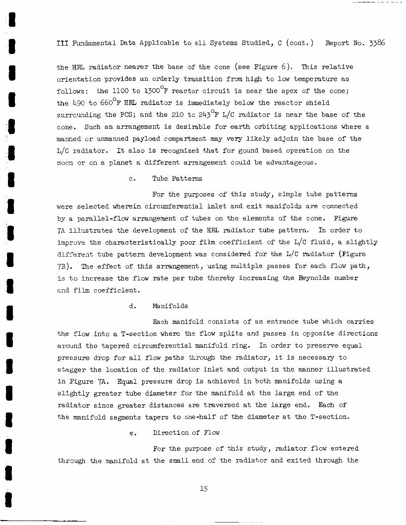
I11 Fundamental Data Applicable t o a l l Systems Studied, C (cont . ) Report No. 3386
t h e HRL r a d i a t o r nearer t he base of t h e cone (see Figure 6) . o r i e n t a t i o n provides an order ly t r a n s i t i o n from high t o low temperature a s
follows: t he 1100 t o 1300°F reactor c i r c u i t is near t h e apex of t h e cone;
t h e 490 t o 6 6 0 ' ~ HRL r a d i a t o r i s immediately below the r eac to r s h i e l d
surrGunding the PCS; and the 210 t o 243OF L/C r a d i a t o r i s near t h e base of t h e
cone. Such an arrangement i s des i rab le f o r e a r t h o rb i t i ng app l i ca t ions where a
manned or unmanned payload compartment may very l i k e l y ad jo in t h e base of t h e
L/C r a d i a t o r .
moon o r on a p lane t a d i f f e r e n t arrangement could be advantageous.
This r e l a t i v e
It a l s o i s recognized t h a t f o r gound based operat ion on t h e
C . Tube Pa t te rns
For the purposes of t h i s s tudy, simple tube pa t t e rns
were s e l e c t e d wherein circumferent ia l i n l e t and e x i t manifolds a r e connected
by a para l le l - f low arrangement of tubes on t h e elements of t h e cone. Figure
7A i l l Q - s t r a t e s t he development of the HRL r a d i a t o r tube pa t t e rn .
improve the c h a r a c t e r i s t i c a l l y poor f i l m c o e f f i c i e n t of t he L/C f l u i d , a s l i g h t l y
d i f f e r e n t tube p a t t e r n development was considered f o r the L/C r a d i a t o r (Figure
p). fs t o increase the flow r a t e pe r tube thereby increas ing the Reynolds number
and f i l m coe f f i c i en t .
In order t o
The e f f e c t of t h i s arrangement, using mult iple passes f o r each flow pa th ,
d. Manifolds
Each manifold cons i s t s of an entrance tube which c a r r i e s
t he f low i n t o a T-section where the f l o w s p l i t s and passes i n opposite d i r ec t ions
around t h e tapered circumferent ia l manifold r ing .
p ressure drop for a l l flow paths through t he r a d i a t o r , it i s necessary t o
s t agge r the loca t ion of the rad ia tor i n l e t and output i n the manner i l l u s t r a t e d
i n Figure 7A0 s l i g h t l y g r e a t e r tube diameter f o r t h e manifold a t t h e l a r g e end of t h e
r a d i a t o r s ince g r e a t e r d i s tances a r e t raversed a t t h e l a rge end. Each of
t h e manifold segments tapers t o one-half of t h e diameter a t t h e T-section.
I n order t o prese.rve equal
Equal pressure drop i s achieved i n both manifolds using a
e. Direct ion of Flow
For t h e purpose of t h i s s tudy, r a d i a t o r flow entered
through the manifold a t t he small end of the r a d i a t o r and e x i t e d through t h e
15
I11 Fundamental Data Applicable t o a l l Systems Studied, C ( con t . ) Report No. 3386
8 manifold a t the l a r g e end of t he r a d i a t o r . The m e r i t s of revers ing t h i s procedure
n - - - dT -- dy Q C
PL
were not invest igated.
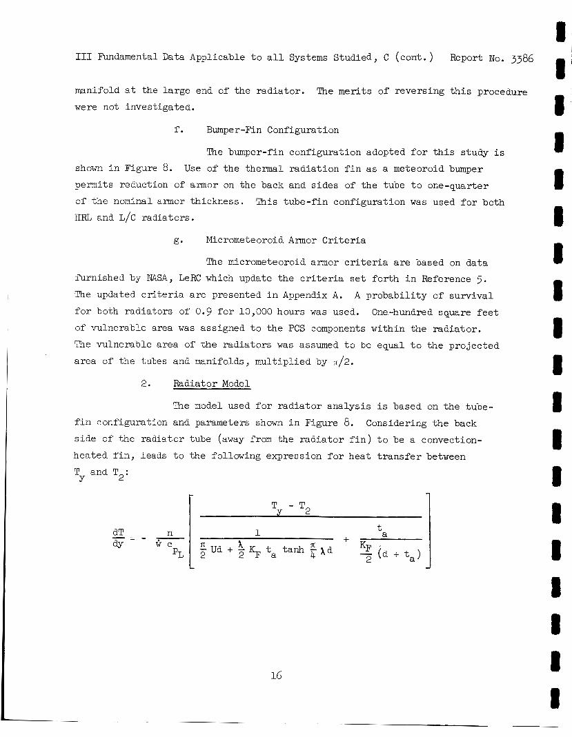
f . Bumper-Fin Configuration
The bumper-fin configurat ion adopted f o r t h i s s tudy i s
shown i n Figure 8. permits reduction of armor on the back and s ides of t h e tube t o one-quarter
of t he nominal a m o r thickness .
H a and L/C rad ia tors .
Use of t h e thermal r a d i a t i o n f i n as a meteoroid bumper
This tube- f in conf igura t ion w a s used f o r both
g. Micrometeoroid Armor Criteria
The micrometeoroid armor c r i t e r i a a r e based on da ta
furn ished by NASA, LeRC which update the c r i t e r i a s e t f o r t h i n Reference 5. The updated c r i t e r i a a r e presented i n Appendix A.
f o r both r ad ia to r s of 0.9 f o r 10,000 hours w a s used.
of vulnerable area was assigned t o the PCS components wi th in the r ad ia to r .
The vulnerable a rea of t h e r ad ia to r s was assumed t o be equal t o t h e p ro jec t ed
a rea of t he tubes and manifolds, mu l t ip l i ed by n/2.
A p robab i l i t y of s u r v i v a l
One-hundred square f e e t
2. Radiator Model
The model used f o r r a d i a t o r ana lys i s i s based on t h e tube-
f i n configurat ion and parameters shown i n Figure 8. s i d e of t he r ad ia to r tube (away from the r a d i a t o r f i n ) t o be a convection-
hea ted f i n , leads t o the following expression f o r hea t t r a n s f e r between
T and T2:
Considering t h e back
Y I- 1
I a t + 1
fi KF 5'(F ta tanh 6 X d - (a + t a l n - Ud + 2 2
-
I T - T2 I
16
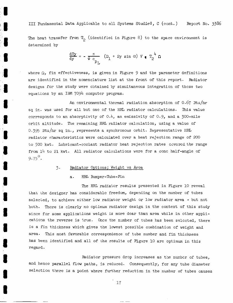
I11 Fundamental Data Applicable t o a l l Systems Studied, C (cont . ) Report No. 3386
The heat t r a n s f e r from T2 ( i d e n t i f i e d i n Figure 8) t o t h e space environment i s
determined by
where S a , f i n e f fec t iveness , i s given i n Figure 9 and t h e parameter d e f i n i t i o n s
a r e i d e n t i f i e d i n t h e nomenclature list a t t h e f r o n t of t h i s r e p o r t . Radiator
designs f o r t h e study were obtained by simultaneous i n t e g r a t i o n of these two
equations by an IBM 7094 computer program.
An environmental thermal r a d i a t i o n absorpt ion of 0.67 Btu/hr
s q i n . w a s used f o r a l l but one of the HRZ; r a d i a t o r ca l cu la t ions . This value
corresponds t o an abso rp t iv i ty of 0.4, a n emiss iv i ty of 0.9, and a 300-mile
o r b i t a l t i t u d e . The remaining HRL r ad ia to r ca lcu la t ion , using a value of
0 395 Btu/hr sq in . , represents a synchronous o r b i t . Representative HRL
r a d i a t o r c h a r a c t e r i s t i c s were calculated over a heat r e j e c t i o n range of 200
t o 500 kwt. Lubricant-coolant r ad ia to r heat r e j e c t i o n r a t e s covered the range
from 14 t o 21 kwt. A l l r a d i a t o r ca lcu la t ions were f o r a cone half-angle of
9.75O.
3. Radiator Options; Weight vs k e a
a. HRL Bumper-Tube-Fin
The HRL r ad ia to r r e s u l t s presented i n Figure 10 revea l
t h a t t h e designer has considerable freedom, depending on t h e number of tubes
se lec ted , t o achieve e i t h e r low rad ia to r weight or low radiator a rea - but not
both. There is c l e a r l y no optimum rad ia to r design i n t h e context of t h i s s tudy
s ince f o r some appl ica t ions weight i s more dear than a rea while i n o ther a p p l i -
ca t ions t h e reverse i s t r u e . Once the number of tubes has been se lec ted , t h e r e
i s a f i n thickness which gives t h e l o w e s t poss ib le combination of weight and
area. This most favorable correspondence of tube number and f i n th ickness
has been i d e n t i f i e d and a l l of t h e r e s u l t s of Figure 10 a r e optimum i n t h i s
regard.
Radiator pressure drop increases as t h e number of tubes,
and hence p a r a l l e l flow paths, is reduced. Consequently, f o r any tube diameter
s e l e c t i o n the re i s a point where fu r the r reduct ion i n t h e number of tubes causes
I11 Fundamental Data Applicable t o a l l Systems Studied, C (cont . ) Report No. 3386
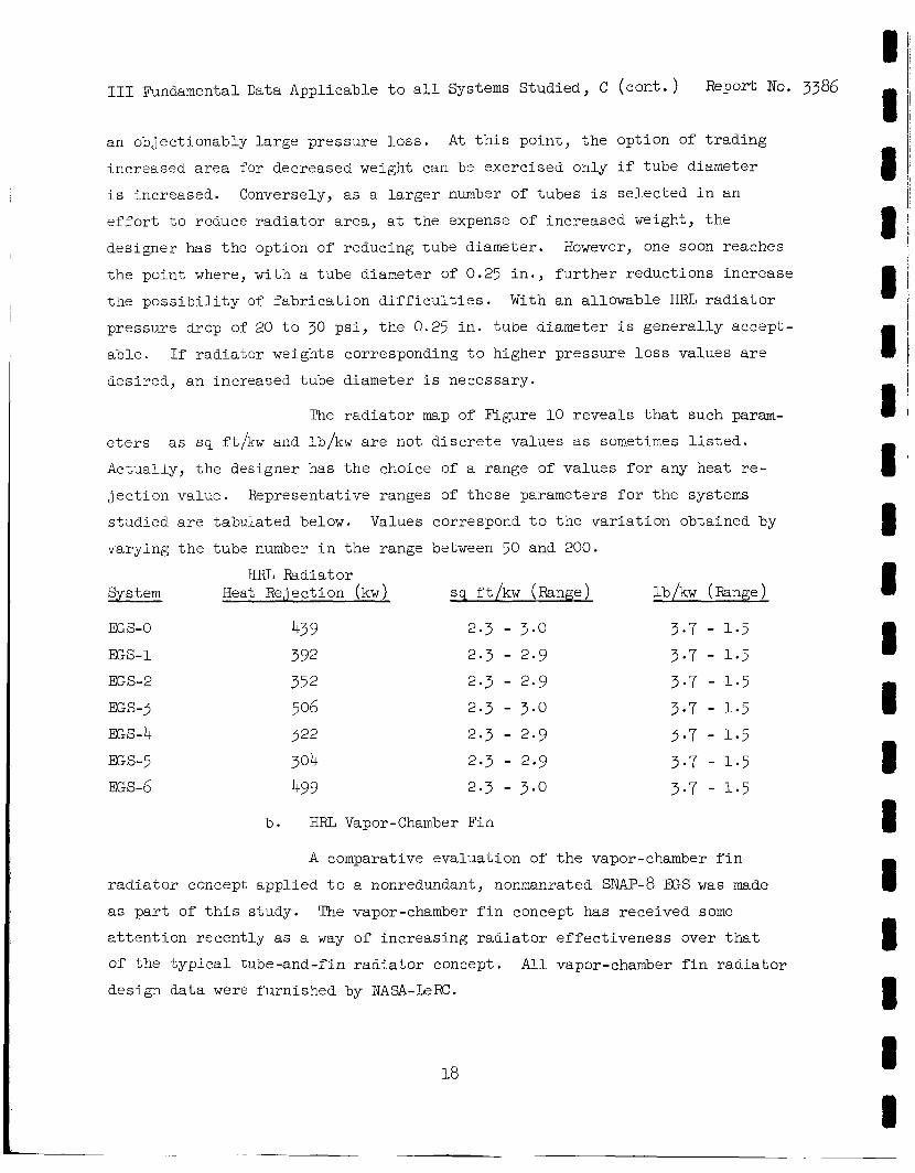
an objectionably l a r g e pressure l o s s .
increased a r e a for decreased weight can be exercised only i f tube diameter
i s increased. Conversely, as a l a r g e r number of tubes i s se l ec t ed i n an
e f f o r t t o reduce r a d i a t o r a r ea , a t t h e expense of increased weight, t he
designer has t h e option of reducing tube diameter.
t h e point where, with a tube diameter of 0.25 i n . , f u r t h e r reductions increase
t h e p o s s i b i l i t y of f a b r i c a t i o n d i f f i c u l t i e s .
pressure drop of 20 t o 30 p s i , t h e 0.25 i n . tube diameter i s gene ra l ly accept-
a b l e .
desired, an increased tube diameter i s necessary.
A t t h i s po in t , t h e option of t r a d i n g
However, one soon reaches
With an allowable HRL r a d i a t o r
I f r ad ia to r weights corresponding t o higher pressure loss values are
The r a d i a t o r map of Figure 10 reveals t h a t such param-
eters
Actually, t h e designer has t h e choice of a range of values f o r any heat re-
j e c t i o n value. Representative ranges of t hese parameters f o r t h e systems
s tudied a re tabulated below. Values correspond t o t h e v a r i a t i o n obtained by
varying t h e tube number i n t h e range between 50 and 200.
System Heat Rejection (kw) sq ft /kw (Range) lb/kw (Range)
as sq ft/kw and lb/kw a r e not d i s c r e t e values as sometimes l i s t e d .
HIiL Radiator
EGS-0 43 9 2.3 - 3.0 3.7 - 1.5 EGS-1 392 2.3 - 2.9 3.7 - 1.5 EGS-2 352 2 .3 - 2.9 3.7 - 1-5 EGS-3 506 2.3 - 3.0 3.7 - 1.5 EGS-4 322 2.3 - 2.9 3 - 7 - 1.5 ES-5 304 2.3 - 2.9 3.7 - 1-5 EGS-6 499 2.3 - 3.0 3.7 - 1 . 5
b. HRL Vapor-Chamber Fin
A comparative evaluat ion of t h e vapor-chamber f i n
r a d i a t o r concept appl ied t o a nonredundant, nonmanrated SNAP-8 EGS w a s made
as p a r t of t h i s study. The vapor-chamber f i n concept has received some
a t t e n t i o n r ecen t ly as a way of increasing r a d i a t o r e f f ec t iveness over t h a t
of t h e t y p i c a l tube-and-fin r a d i a t o r concept. design data were furnished by N A S A - k R C .
All vapor-chamber f i n r a d i a t o r
18
I I 8 8 I I I 8 I I I I I 8 8 8 8 I 8
'I I I 1 8 I 8 I I I 8 1 8 8 I I I 1 I
I11 Fundamental Data Applicable t o a l l Systems Studied, C ( con t . ) Report No. 3386
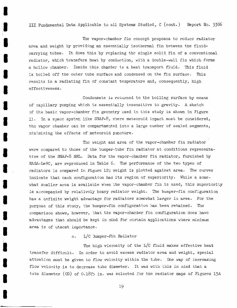
The vapor-chamber f i n concept proposes t o reduce r a d i a t o r
area and weight by providing an e s s e n t i a l l y isothermal f i n between t h e f l u i d -
carrying tubes.
r ad ia to r , which t r a n s f e r s heat by conduction, with a double-wall f i n which forms
a hollow chamber. Inside t h i s chamber i s a heat t ranspor t f l u i d . This f l u i d
i s boi led of f t h e outer tube surface and condensed on the f i n sur face . This
r e s u l t s i n a r ad ia t ing f i n of constant temperature and, consequently, high
e f fec t iveness .
It does t h i s by replacing the s ing le s o l i d f i n of a conventional
Condensate i s re turned t o the bo i l ing sur face by means
of c a p i l l a r y pumping which i s e s sen t i a l ly in sens i t i ve t o g rav i ty .
of t he b a s i c vapor-chamber f i n geometry used i n t h i s study i s shown i n Figure
11. I n a space system l i k e SNAP-8, where meteoroid i m p a c t must be considered,
t h e vapor chamber can be compartmented i n t o a la rge number of sea led segments,
minimizing the e f f e c t s of meteoroid puncture.
A sketch
The weight and area of t he vapor-chamber f i n r a d i a t o r
were compared t o those of t he bumper-tube f i n r a d i a t o r a t condi t ions representa-
t ive of t h e SNAP-8 HRL. Data f o r the vapor-chamber f i n r ad ia to r , furnished by
NASA-kR.C , a r e reproduced i n Table 6. r a d i a t o r s i s compared i n Figure 12; weight i s p lo t t ed aga ins t area.
ind ica t e t h a t each configuration has i t s region of supe r io r i ty .
what smaller area i s available when the vapor-chamber f i n i s used, t h i s supe r io r i ty
i s accompanied by r e l a t i v e l y heavy rad ia tor weight.
has a d e f i n i t e weight advantage for r ad ia to r s somewhat l a r g e r i n a rea .
purpose of t h i s study, the bumper-fin configurat ion has been r e t a ined . The
comparison shows, however, t h a t t h e vapor-chamber f i n configurat ion does have
advantages t h a t should be kept i n mind f o r c e r t a i n appl ica t ions where minimum
area i s of utmost importance.
The performance of t h e two types of
The curves
While a some-
The bumper-fin configurat ion
For t h e
c . L/C Bum-per-Fin Radiator
The high v i scos i ty of t h e L/C f l u i d makes effective heat
t r a n s f e r d i f f i c u l t . I n order t o avoid excess r ad ia to r area and weight, s p e c i a l
a t t e n t i o n must be given t o flow ve loc i ty within t h e tube.
flow v e l o c i t y i s t o decrease tube diameter.
tube diameter (OD) of 0.1875 i n . was se l ec t ed f o r t he r a d i a t o r maps of Figures l 3 A
One way of increasing
It w a s with t h i s i n mind t h a t a
19
I I11 Rmdamental Data Applicable t o a l l Systems Studied, C (cont. ) Report No. 3386
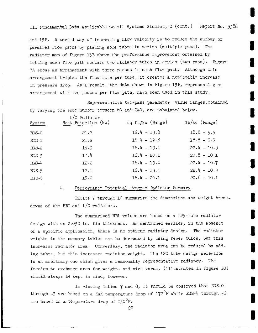
and l 3 B . p a r a l l e l flow paths by placing some tubes i n s e r i e s (mul t ip le pas s ) .
r a d i a t o r map of Figure l 3 B shows t h e performance improvement obtained by
l e t t i n g each flow path contain two r a d i a t o r tubes i n s e r i e s (two pass ) .
7A shows an arrangement with t h r e e passes i n each flow path.
arrangement t r i p l e s t h e flow r a t e per tube, it c r e a t e s a not iceable increase
i n pressure drop. As a r e s u l t , t h e da ta shown i n Figure l 3 B , represent ing an
arrangement w i t h t w o passes per flow path, have been used i n t h i s s tudy.
A second way of increas ing flow v e l o c i t y i s t o reduce t h e number of
The
figure
Although t h i s
Representative two-pass parameter value ranges,obtained
by varying t h e tube number between 60 and 240, are t abu la t ed below.
System Heat Rejection (kw) sq ft /kw (Rmge) lb/kw (Range) L/C Radiator
ES-0
EGS-1
a s - 2
E S - 3
as-4 as-5 as-5
2102
21"2
1.3 -9 17.4 12 .2
12 .1
15 .O
16.4 - 19.8 18.8 - 9.5 16.4 - 19.8 18.8 - 9.5 16.4 - 19.4 22.4 - 10.9 16.4 - 20.1 20.8 - 10.1 16.4 - 19.4 22.4 - 10.7
16.4 - 19.4 22.4 - 10.9 16.4 - 20.1 20.8 - 10.1
4 Performance Po ten t i a l Program Radiator Summary
Tables 7 through 10 summarize t h e dimensions and weight break-
downs of t h e HRL and L/C r a d i a t o r s .
The summarized HRL values a r e based on a 125-tube r a d i a t o r
design with an 0.03O-in. f i n th ickness . A s mentioned e a r l i e r , i n t h e absence
of a s p e c i f i c appl ica t ion , t he re i s no optimum r a d i a t o r design. The r a d i a t o r
weights i n t h e summary t a b l e s can be decreased by using fewer tubes, but t h i s
increases radiat ,or a r ea . Conversely, t he r a d i a t o r area can be reduced by add-
ing tubes, but t h i s increases r a d i a t o r weight.
i s an a r b i t r a r y one which gives a reasonably r ep resen ta t ive r a d i a t o r .
freedom t o exchange a r e a f o r weight, and v i c e versa , ( i l l u s t r a t e d i n Figure 10)
should always be kept i n mind, however.
The 120-tube design s e l e c t i o n
The
I n viewing Tables 7 and 8, i t should be observed t h a t ES-0 0 through -3 a r e based on a NaK temperature drop of 172 F while EGS-4 through -6
a r e based on a temperature drop of 150°F. 20
I11 Fundamental Data Applicable t o a l l Systems Studied, C (cont. ) Report No. 3386
Similarly, t h e summarized L/C r a d i a t o r values i n Tables 9 and 10 a r e based on a 120-tube design with an O.03O-in. f i n thickness and two
passes per flow path. This a l s o i s an a r b i t r a r y but representa t ive s e l e c t i o n .
D. STRUCTURAL CONCEPTS
In t h e absence of an establ ished f l i g h t - s t r u c t u r e design f o r t h e
SNAP-8 FCS some judgments were necessary t o e s t a b l i s h a reasonable basis f o r
s t r u c t u r a l concepts and weights. Therefore, evaluat ion of s t r u c t u r a l concepts
w a s performed during t h i s study; however, a de t a i l ed s t r u c t u r a l design or
prec ise weight determination i s beyond the scope of t h i s study. For t he base-
l i n e system EGS-0, s t r u c t u r a l weight was based on previous SNAP-8 s t r u c t u r a l
s tud ies .
The s t r u c t u r a l concepts used i n es t imat ing t h e s t r u c t u r a l weights
given i n t h i s r epor t are s t rongly influenced by the general arrangement d i s -
cussed i n Section I I 1 , A .
concept used a r i g i d t russ - type frame capable of supporting a l l of t he PCS
components and the nuclear system. This design concept does not provide any
support t o t h e r a d i a t o r nor assume any support from it. A f t e r some estimates
were made regarding t h e s t r u c t u r a l s t rength of t he conica l r ad ia to r , add i t iona l
s t i f f e n i n g of t h e r a d i a t o r s t ruc tu re w a s provided by means of longi tudina l
ha l f - sec t ions and circumferent ia l "Z" r i ngs below t h e base of t he frame, extend-
ing down t h e conica l envelope t o the base of t h e r a d i a t o r assembly. It w a s
ca lcu la ted t h a t t h i s combined s t ruc ture , comprised of the r ad ia to r with t h e
added s t i f f e n e r s and t h e r i g i d frame supporting t h e PCS and the nuclear system,
i s capable of withstanding the launch acce le ra t ion loads i n conformance t o t h e
SNAP-8 environmental spec i f i ca t ion (Reference 6 ) .
When t h e study w a s i n i t i a t e d , t h e SNAP-8 s t r u c t u r a l
For t h e improved systems, s t a r t i n g with GS-1, a l t e r n a t e s t r u c t u r a l
concepts were examined i n order t o develop a concept t h a t w a s somewhat c lose r t o
optimum. Preliminary ca lcu la t ions indicated t h a t the tube-in-f in r a d i a t o r
design i n t h e conica l configuration was, i n i t s e l f , an e f f i c i e n t s t ruc tu re . By
t h e use of r e l a t i v e l y l ightweight s t i f f e n e r s , it w a s poss ib le t o use t h i s
s t r u c t u r e t o support not only i t s e l f but t h e PCS and the nuclear system as
W e l l .
l i g h t e r s t r u c t u r e than would be possible using a r i g i d frame.
The add i t ion of r ings and s t r inge r s t o t h i s component r e s u l t s i n a much
Calculations
21
111 Fundamental Data Applicable t o a l l Systems Studied, D (cont . ) Report No. 3386
have shown t h a t t h e r ings and s t r i n g e r s i l l u s t r a t e d i n Figure 14 a r e satis-
fac tory . No attempt w a s made t o optimize these re inforc ing elements.
Using t h e s t i f f ened r a d i a t o r as t h e primary s t r u c t u r a l member,
t h e concept shown i n Figure 15 w a s developed. In t h i s design the nuclear
system, which i s a compact r i g i d assembly, i s d i r e c t l y supported by t h e
r a d i a t o r through a mounting r i n g a t tach ing t h e base of t h e s h i e l d t o t h e t o p
of t he r a d i a t o r . The PCS components, supported by t h e r a d i a t o r through tens ion
members, a r e packaged as sub-assemblies t o provide f o r a r e l a t i v e l y small
number of f o c a l points f o r supports. I n order t o reduce t h e number of tens ion
members required, t h e PCS components have been grouped i n t o four assemblies:
(1) PNL €MA, expansion reservoi r , and PLR when used i n PNL; (2) tu rb ine ,
a l t e rna to r , , and condenser assembly; ( 3 ) bo i l e r ; and ( 4 ) MPMA, HRL NaK PMA,
L/C PMA and mercury i n j e c t i o n system (MIS). cables or rods; the following discussion uses t h e t e r m cable f o r convenience.
Tension members might be e i t h e r
The primary loop NaK PMA and assoc ia ted components are f ixed
d i r e c t l y t o t h e nuclear sh i e ld assembly.
( T U ) i s em-rently designed s o t h a t t h e a x i s o f i t s t runnion mountings passes
through i t s center of masso This f ea tu re has been preserved i n t h i s study.
Four cables are at tached t o each s ide of t h e tu rb ine mounting.
t he e igh t cables supporting t h e T U a t i t s center of mass extend t o the
r a d i a t o r where they are fastened s o as t o d i f fuse t h e i r loads through t h e
r a d i a t o r sk in and s t r i n g e r s . Cable o r i en ta t ion i s t o be se l ec t ed s o as t o
hold t h e TAA against a l l an t i c ipa t ed loading.
or a t any instantaneous t i m e during launch, o r b i t , o r s t a r tup , they provide
pos i t i ve , f i xed support.
during maximum f l i g h t acce le ra t ion condi t ions e
diameter cables would be more than adequate t o carry t h e load.
supported a t two polnts with t h e cables s o arranged and preloaded as t o account
f o r t he spr ing r a t e of t h e b o i l e r he l ix . The mercury NaK, and L/C pumps and
t h e i r assoc ia ted components are supported a t t h e i r combined mass center i n a
manner comparable i n p r inc ip l e t o t h a t of t h e TAA support .
The tu rb ine -a l t e rna to r assembly
Consequently,
During s teady-s ta te conditions,
The cables are preloaded t o keep them i n tens ion
It w a s ca lcu la ted t h a t 5/16-in.
The b o i l e r i s
Exact cable or ientat ion, , preloading and f i n a l s e l e c t i o n of cable
couplings and attachment poin ts were not determined i n t h i s study. Preliminary
22
111 Fundamental Data Applicable to a11 Systems Studied, D (cont. ) Report No. 3386
calculations were made only to establish the feasibility of the concept.
By using this structural design, a weight saving of 1100 lb was estimated.
This structural concept was used for all of the improved systems, EGS-1 through -6.
Structural continuity between the HRL and L/C radiators is
necessary in order to transfer the loads to the payload structure which in
turn is supported by the payload mounting ring of the Saturn IVB stage. In
order to establish structural weight requirements, it was necessary to con-
sider the design of the structural joint at each of the above interfaces.
Figure 14 shows a typical joint used in estimating the weight of the radiator structural supports.
E. SYSTEM PERFORMANCE ANALYSIS
Analysis of the SNAP-8 E S requires iterative calculations which are best handled by a computer.
SNAP-8 development program for steady-state performance analysis.
gram, described in Reference 7, was given the code name of SCAN (System Cycle ANalysis). ing "nrt variables which describe the steady-state performance of the SNAP-8
EGS. When n-m independent variables are assigned fixed values, and a complete
set of values (initial guesses) are given for the unknown variables, the
computer program uses a variation of the Newton-Rapheson method for iterating the variables until a power balance is achieved.
mentioned above, the SCAN program requires the following input; piping
characteristics, component performance characteristics, mercury thermodynamic
properties, and selected state-points. Component characteristics are defined by curve-fitting actual test data wherever possible.
computer calculates final values of the unknown variables which will match the
variables assigned fixed values that are supplied as part of the input. In
the process, the computer a l s o calculates trim-orifice pressure drops for each loop to achieve a balance between the head rise of the pump and the pressure
losses throughout the loop. The computer output includes a system diagram with all significant temperatures, pressures, flow rates and input and output power;
A digital computer program was written for the This pro-
The program incorporates a set of ?M1' functional equations contain-
In addition to the variables
With these inputs, the
I11 Fundamental Data
a l i s t of t h e values
Applicable t o a l l Systems Studied, E (cont . )
of a l l of t h e n var iab les ; and a l i s t of o ther important
Report No. 3386
ca lcu la ted values, such as ove ra l l e f f ic iency , a l t e r n a t o r e f f ic iency , and
a l t e r n a t o r kva output.
I n the present study, t he computer program w a s modified t o t h e
extent of replacing, adding, or de le t ing equations as necessary t o def ine t h e
system being analyzed. The number of equations used ranged from 53 t o 56 and
the number of var iables from 70 t o '72. Typically, t h e systems were analyzed
with e i t h e r t h e ne t output power or t h e r eac to r input power f ixed .
parameters t h a t were f ixed inputs t o the computer a r e t h e tu rb ine e f f ic iency ,
the turb ine i n l e t pressure, t he turb ine e x i t pressure, and the r eac to r coolant
o u t l e t temperature.
Other
24
I 1 I I 8 I I I I I 1 I I 8 I (I
8 I 1
Report No. 3386
I V . BASELINE SYSTEM - EGS-0
Charac te r i s t i c s of the basel ine e l e c t r i c a l generat ing system (EGS-0) were
es tab l i shed pr imar i ly by the experimental da t a on SNAP-8 PCS components t h a t
were ava i lab le a s of September 1965. Where component experimental da t a were
not ava i l ab le , the preva i l ing de ta i led design ca l cu la t ions and drawings were
used. Proper t ies of the nuclear system, s t ruc tu re and r a d i a t o r s were i d e n t i f i e d
a s described i n the previous sec t ion . On the b a s i s of t h i s information, a steady-
s t a t e performance ana lys i s and a de ta i led weight compilation of EGS-0 were made;
da ta used t o evaluate the changes incorporated i n the improved systems.
A . SELECTION OF OPERATING CONDITION FOR ANALYSIS
To completely analyze the performance of the power system, i t i s
necessary t o consider many d i f f e r e n t conditions which might be encountered i n a
t y p i c a l space mission; e .g . , var ia t ions i n (1) the inc ident heat input t o the
r a d i a t o r s (sun or shade), (2) the e l e c t r i c a l load demanded by the vehicle (100
t o O$), and (3) the g rav i ty f i e l d (0 to 1 g or g r e a t e r ) . I n the present study,
one operat ing condi t ion only i s o f i n t e r e s t , s ince the objec t i s t o compare the
e f f e c t s of i n t e r n a l power system improvements. The condi t ions chosen f o r compar-
i son of a l l of the SNAP-8 systems character ized i n the study a re zero gravi ty ,
100% vehicle load, and maximum sun and e a r t h inc ident hea t input t o the r a d i a t o r s
i n a 300 n a u t i c a l mile o r b i t . I n general, these are the conditions which y i e ld
the lowest ava i l ab le e l e c t r i c a l power for a given SNAP-8 system.
One o ther condition which deserves spec ia l mention i s the v a r i a t i o n
i n temperature of the NaK leaving the r e a c t o r . This temperature i s continuously
measured and maintained by the reactor c o n t r o l l e r wi th in the l i m i t s of 1280 and
1330'F.
the EGS because it a f f e c t s conditions i n the b o i l e r . Since i t w a s not obvious
which temperature extreme would yield the lowest ava i lab le output power, the
performance of EGS-0 a t both temperature condi t ions was analyzed. It was found
t h a t s l i g h t l y lower output power (0.8 kw) was obtained when the r eac to r o u t l e t
temperature i s a t i t s upper l i m i t of 1330 F. Consequently, t h i s condi t ion was
se lec ted as a b a s i s f o r comparing the performance of a l l of the systems evalu-
a ted i n t h i s study.
This v a r i a t i o n i n temperature s l i g h t l y inf luences the performance of
0
IV base i ine System - EGS-o (cont . ) Report No. 3386
B . PERFORMANCE AnTD WEIGET OF EGS-0
The r e s u l t s of the performance ana lys i s of EGS-0 opera t ing a t the
upper temperature l i m i t of the r e a c t o r coolant a r e summarized i n Figure 16. This summary performance cha r t gives a l l s i g n i f i c a n t s teady-s ta te opera t ing da ta
for the system presented i n a standardized format.
s i g n i f i c a n t tzmperatures, p ressures and flow r a t e s f o r each loop a r e i d e n t i f i e d
on a schematic diagram. Below the diagram, desc r ip t ive f e a t u r e s def in ing the
makeup of the systsm a r e tabula ted . This l i s t w i l l he lp t o d i s t i n g u i s h modifica-
t i o n s inzorporated i n t o the improved systems descr ibed i n l a t e r s ec t ions of t h i s
r e p o r t . A l s o tabulated below the schematic diagram a r e the o v e r a l l performance
parameters of the EGS. On the l e f t s ide of the diagram, the a l t e r n a t o r power
d i s t r i b u t i o n and t h e thermal power ( i n kw) d i s s ipa t ed by the L/C r a d i a t o r a r e
t abu la t ed . Or, the r i g h t s ide of the cha r t i s a l i n e diagram of system configur-
a t i o n showirlg a x i a l height of the r a d i a t o r s appl icable t o the system. This cha r t
format was xsed f o r each of the systems analyzed t o f a c i l i t a t e comparison.
A t the top of Figure 16
Regarding the pressure values i d e n t i f i e d on the schematic diagram,
a word of explanat ior i s i n order . For the NaK loops, the pressures given
represent the t o t a l loop przssur? drop. I n EGS-0 (and i n some of the improved
systems), t hc NaK PMA generates a higher pressure r ise than the loop r equ i r e s .
In t h a t case, the excess AP i s d i s s ipa t ed by a trimming o r i f i c e loca ted a t the
pump discharge p x t not shown on the diagram.
var ious pressures around the loop a re i d e n t i f i e d , the pressure a t the pump d i s -
Zharge i s t h a t produced by the pump upstream of a flow con t ro l valve (not
showl?). Tn a i l of the systems analyzed, the mercury pump discharge pressure
i s h igher t h a c tha t r squi red t o meirt the loop AP requirements. This i s seen
i n the diagram by comparing the pressure a t the pump e x i t with t h a t a t the
For the mercury loop, where
S o i l e r iz l le t a
k e overal.1 e f f i c i e n c y of EGS-0 (Figure 16) i s 7.0% and the ne t
power output i s 36.0 kwe. The r a t e d power output of the s ~ ~ p - 8 EGS i s 35 h e .
EGS-0 meets t h i s requirement with a one k i lowat t margin for performance degra-
da t ion over 10,000 hours of opera t ioo . It was planned t h a t the system ana lys i s
26
0 8
R I 1 I E E 0 1
I V Baseline System - EGS-0, B (cont. ) Report No. 3386
would be normalized a t 40 kw net power, thereby providing 5 kw f o r performance
degradation ( t h i s being an arbitrary, but generous number).
analyzing E%S-0 t h e system would not produce t h e desired 40 kwe net output
without exceeding one, o r more, of the component design l imi t a t ions . The
EGS-0 power output of 36.0 i s l i m i t e d by a mercury flow r a t e of 12,000 lb /h r
a t the assumed turb ine i n l e t pressure and temperature and f l u i d flow artba.
However? i n
The total. weight of EGS-0 i s given i n the performance summary of
Figure 16 as 11,003 lb.
the nuclear system, t h e rad ia tors , and supporting s t ruc ture . A de t a i l ed
t abu la t ion of weights i s given i n Appendix B of t h i s report .
This value includes t h e weight of a l l PCS components,
The performance of EGS-0 a t the lwer temperature l i m i t of the
r eac to r cQolant is summarized i n Figure 17. It is seen t h a t t he net power
output increases t o 36.8 kwe Bnd t h a t mercury flow rate and turb ine i n l e t
pressure increase a small amount. These changes a r e due t o reduction i n
mercury pressure drop through the boiler associated w i t h t he change i n b o i l e r
NaK-side temperature l eve l s .
PRECEDING PAGE BLANK NOT FILMED.
Report No. 3386
V . BASXS FOR PERFORMANCE IMPROVEMENT
Performance improvement i n the context of t h i s study i s def ined a s weight
reduct ion, r a d i a t o r a rea reduct ion, ava i lab le power increase , and o v e r a l l e f f i -
ciency increase .
To ta l r a d i a t o r a rea i s an important f a c t o r i n applying any power system
t o a space vehic le s ince the s i z e of the boos te r payload envelope may l i m i t the
amount of surface a rea ava i l ab le f o r t h i s purpose. Therefore, ways of reducing
r a d i a t o r a rea were inves t iga ted . Not only increased o v e r a l l e f f i c i e n c y reduces
r a d i a t o r a r ea , b u t the temperatures a t which the energy i s r ad ia t ed has a d i r e c t
z f f e c t OG a rea . Radiat ing temperatures a l s o were evaluated i n the course of
t h i s s tudy .
Weight reduct ion i s not d i r e c t l y r e l a t e d t o o v e r a l l e f f i c i e n c y b u t r e s u l t s
from reduced r a d i a t o r a rea due t o improved o v e r a l l e f f i c i ency . If the saving i n
s t r u c t u r e i s not included, i t can be s t a t ed t h a t a g rea t e r weight reduct ion was
achieved by increas ing o v e r a l l e f f i e i eney than was obtained by reducing PCS com-
ponent weights
I n the cases where the r eac to r output power i s f i xed a t 600 kwt, a s i n
EGS-3 and -6, the ne t power output i s d i r e c t l y r e l a t e d t o the overall system
e f f i c i ency . I n a l l o the r systems, from EGS 2 and up, the c e t power output was
f ixed a t 40 kwe.
r e i a t e d t o the o v e r a l l system e f f i c i ency .
The r eac to r power required f o r these systems i s inverse ly
A. IMPROVEMENT I N OVERALL EF'FICIEMCY
In order t o i d e n t i f y what kinds of modif icat ions o f f e r the g r e a t e s t
ga in i n e f f i c i ency , an assessment of the power d i s t r i b u t i o n throughout the
SNAP-8 system was madep By examining the power l o s s e s occurr ing i n the seve ra l
loops and components of EGS 0, i t i s possible t o develop a l o g i c a l plan f o r i m -
proving e f f i c i e n c y . Figure 18 depic t s the d i s t r i b u t i o n of power i n EGS-0 a s i t
i s b e i s g transformed from thermal t o e l e c t r i c a l power by the b o i l e r , tu rb ine ,
and a l t e r n a t o r . Overal l e f f i c i ency i s the r a t i o of the ne t e l e c t r i c a l output
29
v Basis f o r Performance Improvement, A ( con t . ) Report No. 3386
36 .o 5 12
t o r eac to r thermal input (- = 7.0) . The o v e r a l l e f f i c i e n c y can be defined
3s >io = T~ ~~y~ 72p, where -&I i s the Rankine cycle e f f i c i e n c y and i s equa l t o
the r a t i o of the energy ava i l ab le t o the turbine divided by the t o t a l thermal
energy i n the f l u i d .
c
- .235. q t equals the t o t a l t u r - I n Figure 16,TC = - - 120 5 10
64.9 bine e f f i c i ency equal t o 7 = - = .5~1). Ta equals a l t e r n a t o r e f f i c i e n c y t 120 equals p a r a s i t i c e f f i c i e n c y defined as the n e t e l e c -
t r i c a l outpilt divided by the gross e l e c t r i c a l output of the a l t e r n a t o r
[y = 36.0 = .645) . It i s l o g i c a l t o s t a r t f i r s t on 0.235 (7 ) s ince t h i s i s P 55.8 C
the lowest value. This value, however, i s the most d i f f i c u l t t o increase
s i n c e , f o r t h i s study, the r e a c t o r o u t l e t temperature must remain constant
due t o the c h a r a c t e r i s t i c s of the r e a c t o r f u e l elements. The only way t o in-
crease t h i s value i s t o increase the pressure r a t i o ; r e f e r t o Sect ion V , D f o r
a more de t a i l e d discussion.
The next e f f i c i e n c y value i s 0.541 (2t) which i s the turbine
e f f i c i e r c y . This -Jalue i s determined by the turbine pressure r a t i o , number of
s t s g e s , blade ve loc i ty t o nozzle v e l o c i t y r a t i o , and the s i z e and shapes of the
flow psssages ( s e e Section v , c , ~ ) .
The a l t e r n a t o r e f f i c i e n c y of 0.860 (?,) i s determined by the
a l t e r n a t o r design and the a l t e rna to r - load power f a c t o r . Power f a c t o r and a l t e r -
ga to r des ign are discussed i n Section V , C 4.
The p a r a s i t i c load determined the value of 17 = 0.645. This P
value can be increased by reducing pump power required, increasing the e f f i -
ciency of the e l e c t r i c a l con t ro l s , and inc reas ing the e f f i c i e n c y of the pump
and motors used i n the system.
In t h i s study, a l l fou r e f f i c i e n c i e s which def ine the over-
a l l system e f f i c i ency were improved. This increased o v e r a l l e f f i c i e n c y re-
sults i n several improvements; reduced r a d i a t o r a r e a , reduced weight , increased
power output, and reduced power input f o r a spec i f i ed output .
30
V Basis f o r Performance Improvement (cont .) Report No. 3386
B . WEIGHT FEDUCTION
Pa r t of the e f f o r t directed toward the eva lua t ion of EGS-1 consis ted
of a weight reduct ion study of PCS components. Each component of the PCS was
c r i t i c a l l y reviewed by examining d e t a i l drawings t o i d e n t i f y p a r t s which could
be l igh tened without a f f e c t i n g component func t ion or r e l i a b i l i t y . Much of the
weight reduct ion was e f f ec t ed by replacing heavy bol ted f langes with welded
pipe connections. In some cases, component housings were thinned bu t only
where i t was determined t h a t s t r e s ses were f a r below allowable l e v e l s Table
1.1 summarizes the amount and nature of the weight reduct ions estimated f o r the
major components. The rev ised weights shown i n Table 11 were used i n compiling
the de t a i l ed weight t a b l e s f o r EGS-1 presented i n Appendix B.
-xed as a b a s i s f o r the weight breakdown of the l a t e r systems, a f t e r making
adjustments t o account f o r subsequent component modif icat ions.
They a l s o were
Referr ing t o Table 11, a reduct ion of 1545 l b i n PCS dry weight
may be noted. Of t h i s t o t a l , the l a r g e s t s ing le increment i s 1100 lb a t t r i b -
u t ab le t o a major change i n the s t r u c t u r a l design concept. The remaining
445-1b reduct ion f o r a l l of the other PCS components amounts t o about 12% of
the o r i g i n a l weight of the PCS l e s s the structure.. This i s a r e l a t i v e l y small
r d u c t i o n , r e f l e c t i n g the r a t h e r cautious approach of the weight study. Some
a d d i t i o n a l weight savings may be observed by comparing the de t a i l ed weight
t ab le s for EGS-3 and EGS-1 i n Appendix B.
reduced 57 lb a s a by-product of the b o i l e r weight ana lys i s described i n
Refereme 8; a reduction i n rad ia tor weight of 88 lb i s due t o a reduct ion i n
hea t r e j e c t e d .
amounting t o over 600 It3 i n EGS-5.
The primary loop NaK inventory i s
This e f f e c t becomes increas ingly important i n the l a t e r systems,
C . COMF'OYENT MODIFICATIONS AIXD SUBSTITUTIONS
The p r inc ipa l technique employed t o eva lua te the performance improve-
ment p o t e n t i a l of the SNAP-8 EGS was tha t of examining the performance of ind i -
v idua l components. De-
s ign modif icat ions (o r , i n some cases, e n t i r e l y d i f f e r e n t designs) which might
increase e f f i c i ency or decrease p a r a s i t i c l o s ses were analyzed t o es t imate ind i -
v idua l performance ga in . Modified ox subs t i t u t ed components were then incorpor-
a ted a n a l y t i c a l l y i n one or more of the systems t o determine t h e i r e f f e c t on
EGS performance.
Each of the major components of the PCS was reviewed.
Some of the component modifications were el iminated a f t e r
31
V Basis f o r Performance Improvement, C ( c o n t . ) Report No. 3386
ana lys i s indicated t h a t gains were too small or development e f f o r t was too g r e a t
t o j u s t i f y fu r the r considerat ion. The following paragraphs d iscuss the na ture
and e f f e c t of the modifications and t h e i r app l i ca t ion i n the var ious improved
sys tems
1. Turbine
The turbine was reviewed toevaluate the e f f e c t of design improve-
ments or: the turbine aerodynamic e f f i c i e n c y .
four -s tage , a x i a l flow, impulse-type turbine designed t o operate a t 12,000 rpm.
Labyrinth sea l s a r e used t o minimize i n t e r s t a g e leakage. A t h r u s t balance p i s -
ton on the f i r s t - s t a g e r o t o r i s used t o n e u t r a l i z e axial t h r u s t so t h a t bear ing
loads a r e reduced, thereby increas ing bear ing l i f e . Mercury vapor flowing p a s t
the thrust-balance p i s ton i s verrted d i r e c t l y t o the exhaust. On the b a s i s of
t e s t da t a , the aerodynamic e f f i c i e n c y of t h i s design was determined t o be 57% when the mercury vapor contained 2$ by weight of l i q u i d carryover .
ciency does not include bear ing and sea l - to-space lo s ses which have been es tab-
l i s h e d a s 3 0 3 kw.
The SNAP-8 turbine assembly i s a
This e f f i -
Analysis ind ica ted t h a t performance can be improved by incorpor-
a t i n g the following design modif icat ions:
a . Reduce the diameter and clearances, and improve the
l a b y r i n t h and concent r ic i ty of the t h r u s t balancing pis ton; provides a reduct ion
i n tne bypass flow through the p i s ton .
b . Reduce the present b l ade - t ip c learances; can be reduced
from the present 0.040 t o 0.020 i n . on the b a s i s of thermal expansion da ta .
c . Reduce the nozzle-vane t i p c learances; s u f f i c i e n t reduc-
t i o n el iminates leakage path common t o a l l fou r s t ages .
d . Reduce t r a i l i n g edge thickness of r o t o r blades; can be
reduced f r o m 0.014 down t o 0.006 i n .
These changes were estimated t o increase aerodynamic e f f i c i e n c y
by 7.4 percentage po in t s t o 64.4% w i t h 2% l i q u i d carryover (Reference 9 ) . value was m e d i n the system ana lys i s f o r EGS-1, -2, and -3 a
This
fr, EGS-5 2nd -6, t.he tlrrbine i n l e t p ressure was increased from
Appendix C shows the equat ions used and the assumptions made 240 to 350 ps ia .
i n correctirig the s tage e f f i c i e n c i e s t o account f o r higher p a r t i a l admission
IC I I
v Basis f o r Performance Improvement, c ( con t . ) Report No. 3386
l o s s e s due t o the change i n absolute pressures and pressure r a t i o s . A turbine
e f f i c i ency of 62.5%, obtained by th i s process , was used i n EGS-5 and -6.
A more recent ana lys i s , described i n Reference 10, i nd ica t e s
t h a t the attainment of an e f f i c i ency of 62% would be more probable wi th the
above-l is ted modif icat ions.
pressure of 350 ps i a , an e f f i c i ency of 61% w a s used t o evaluate the performance
of t h a t system. I n a l l systems, i t was assumed t h a t the flow passages were ad-
jzstn,d t o match the mercury flow ra t e s ca lcu la ted i n the system performance ana lys i s .
Therefore, i n EGS-4, which a l s o has a turbine i n l e t
2. NaK Pump Motor Assemblies (NaK PMA)
This component was reviewed t o determine the f e a s i b i l i t y of
reducing i t s required input power. This i s an important cont r ibu tor t o the para-
s i t i c power of the EGS s ince the same assembly i s used i n both the PNL and HRL.
The present SNAP-8 NaK PMA i s driven by a 5800-rpn induct ion motor; i t s character-
i s t i c s a re given i n Figure 19. This type of NaK PMA was used i n EGS-0, -1, and -3 where there i s the requirement for r e l a t i v e l y high-head-rise and flow c h a r a c t e r i s t i c s .
For systems with lower flow r a t e s and lower head-r ise requirements,
such as i n EGS-2 and -4, i t was found t h a t the PMA could be modified i n a simple
way t o reduce the power requi red , The modification consis ted of rewinding the
motors t o produce a 10-pole motor instead of the present 8-po1e motor; reduces
the synchronous speed from 6000 t o 4800 prm. The opera t ing speed for t h i s de-
s ign would be 4800 rpm if a synchronous motor i s used o r 4650 rpm i f an induc-
tfori motor i s employed.
Analysis of the reduced-speed NaK PMA was conducted t o es tab-
l i s h the new H-Q c h a r a c t e r i s t i c and t o determine the power input requirements.
The H-Q and power input of the 4800-rpm synchronous NaK PMA a re given i n Figure
20.
same c h a r a c t e r i s t i c s a t 4650 rpm as given f o r the 4800-rpm assembly.
gain i n pump motor e f f i c i ency i s obtained from the reduct ion of hydrodynamic
l o s s e s associated with the NaK-flooded motor r o t o r and the reduced hydraul ic power
inpar ted t o the pumped NaK.
It i s assumed here t h a t a 3% increase i n impeller diameter w i l l give the
The g r e a t e s t
Table 12 gives a comparison of the lo s ses and input
power with those
and -6 by custo:.
of the 5800 rpm NaK PMA.
A t h i r d c l a s s of N a K PMA
designing the assembly t o
33
was developed a n a l y t i c a l l y f o r EGS-5
match the NaK flow r a t e and reduced
V Basis f o r Performance Improvement, C (cont . ) Report No. 3386
loop AP requirements.
l o s s e s and motor e l e c t r i c a l l o s ses t o obta in input power.
head r i s e and input power vs NaK flow r a t e obtained by t h i s method.
implies t h a t a spec i f i c PMA must be designed f o r each flow r a t e .
design requirements a re shown i n Table 13. t h i s tab le r e f l e c t modifications i n pipe s i z e and components t o reduce loop
hydraul ic impedance
Allowances were made f o r impel ler e f f i c i ency , hydraul ic Figure 21 shows the
This f i g u r e
The s p e c i f i c
The head r i s e requirements given i n
I n addi t ion t o varying the head and power input c h a r a c t e r i s t i c s
of the NaK PMA, the method of cooling the assembly w a s reviewed.
the SNAP-^ PMA's were designed t o operate a t 600 '~ bu t a r e cooled by L/C f l u i s so
t h a t they operate a t 325OF. temperatures of 600 '~ has shown tha t 500°F HRL NaK can be used a s coolant f o r
these assemblies. The input power reduces s l i g h t l y a t the high motor temperature
f o r increased e l e c t r i c a l l o s ses due t o higher winding r e s i s t ance .
of cooling these motors with HRL NaK i s i n a reduct ion of r a d i a t o r a r ea .
i s a net red-Action of approximately 1 5 sq f t f o r each kw t ransfer red from the L/C
r a d i a t o r t o the 3RL r a d i a t o r .
through EGS-6
The motors f o r
Recent t e s t s made on a NaK PMA operat ing a t motor
The advantage
There
NaK cooling of the NaK PMA's was used i n EGS-2
3 . Pkrcury Pump
The present SNAP-8 mercury PMA c h a r a c t e r i s t i c s have been found
t o be s s t i s f a z t o r y f o r a l l systems considered i n t h i s study a s long a s the system
s t a t e -po in t s a?? such a s t o provide adequate suc t ion pressure t o the pump.
PMA employs a l iqu id- to- l iqu id j e t pump t o increase the i n l e t pressure t o the cen-
t r i f t l ga l impel ler .
termined by the jet-pump requirements, shown i n Figure 22.
e t e r s influence the NPSEI: ava i lab le :
r a d i a t o r NaK A T .
NPSH f o r operation of the mercury PMA-
duct ion i n turbine e x i t pressure w a s des i red , the pump HPSH requirement could be
reduced by r e l a t i v e l y simple design changes.
This
The NPSH requirements of the mercury pump a r e , therefore , de-
Two independent param-
the turbine exhaust pressure, and the HRL
All of the systems synthesized i n the study provide s u f f i c i e n t
However, i f f o r some appl ica t ions a r e -
The SNAP-8 MPMA a l s o includes a motor scavenger impeller which
absorbs 0.65 kw s h a f t power.
a ted , thereby reducing the motor input power by 0.7b kw (based on a motor e f f i -
ciency of 87.8%).
The study indica ted t h a t t h i s p a r t could be elimin-
This modification was adopted i n EGS-4, -5, and -60
34
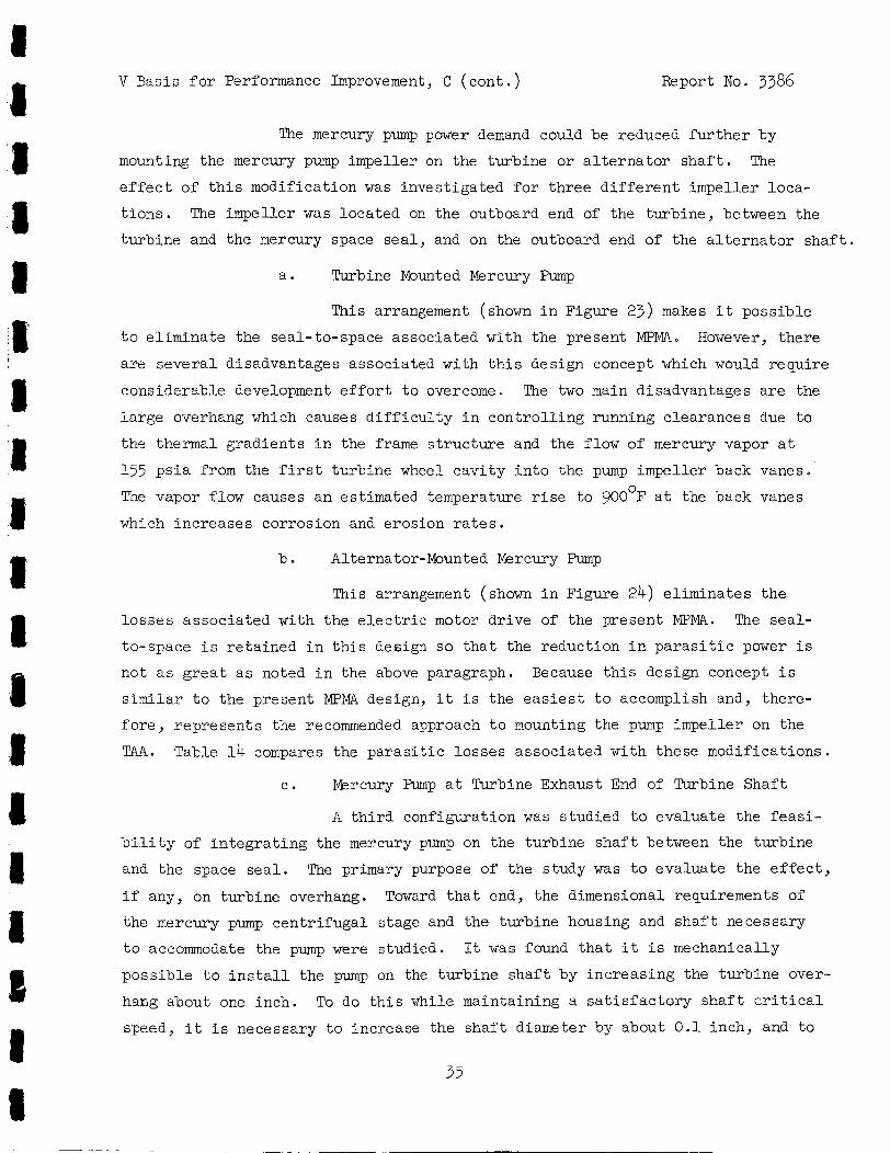
V Basis f o r Performance Improvement, C ( con t . ) Report No. 3386
The mercury pump power demand could be reduced f u r t h e r by
mounting the mercury pump impeller on the turbine or a l t e r n a t o r sha f t . The
e f f e c t of t h i s modification was invest igated f o r three d i f f e r e n t impeller loca-
t i ons . The impeller was located on the outboard end of the turbine, between the
turbine and the mercury space s e a l , and on the outboard end of the a l t e r n a t o r sha f t .
a . Turbine Mounted Mercury Pump
This arrangement (shown i n Figure 23) makes i t possible
t o e l imina te the seal-to-space associated with the present MPMA. However, there
a re severa l disadvantages associated with t h i s design concept which would require
considerable development e f f o r t t o overcome. The two main disadvantages a r e the
la rge overhang which causes d i f f i c u l t y i n cont ro l l ing running clearances due t o
the thermal gradients i n the frame s t ruc tu re and the flow of mercury vapor a t
155 p s i a from the f i r s t turbine wheel cav i ty i n t o the pump impeller back vanes.
The vapor flow causes an estimated temperature r i s e t o 900°F a t the back vanes
which increases corrosion and erosion r a t e s .
b. Alternator-Mounted Mercury Pump
This arrangement (shown i n Figure 24) e l imina tes the
l o s s e s a.ssociated with the e l e c t r i c motor dr ive of the present MPMA. The sea l -
to-space i s re ta ined i n t h i s design so tha t the reduction i n p a r a s i t i c power i s
not as g r e a t a s noted i n the above paragraph. Because t h i s design concept i s
s t m i l a r t o the present MPMA design, i t i s the e a s i e s t t o accomplish and, there-
f o r e , represents the recommended approach t o mounting the pump impeller on the
T.A-4. Table 14 compares the p a r a s i t i c losses associated with these modifications
c . Mercury Pump a t Turbine Exhaust End of Turbine Shaft
A t h i rd configuration was studied t o evaluate the f e a s i -
b i l i t y of i n t e g r a t i n g the mercury pump on the turbine sha f t between the turbine
and the space s e a l . The primary purpose of the study w a s t o evaluate the e f f e c t ,
i f any, on turbine overhacg. Toward t h a t end, the dimensional requirements of
the mercury pump cent r i fuga l stage and the turbine housing and s h a f t necessary
t o accommodate the pump were studied. It was found t h a t i t i s mechanically
poss ib le t o i n s t a l l the pump on the turbine sha f t by increas ing the turbine over-
hang about one inch. To do t h i s while maintaining a s a t i s f a c t o r y s h a f t c r i t i c a l
speed, i t i s necessary t o increase the sha f t diameter by about 0 .1 inch, and to
35
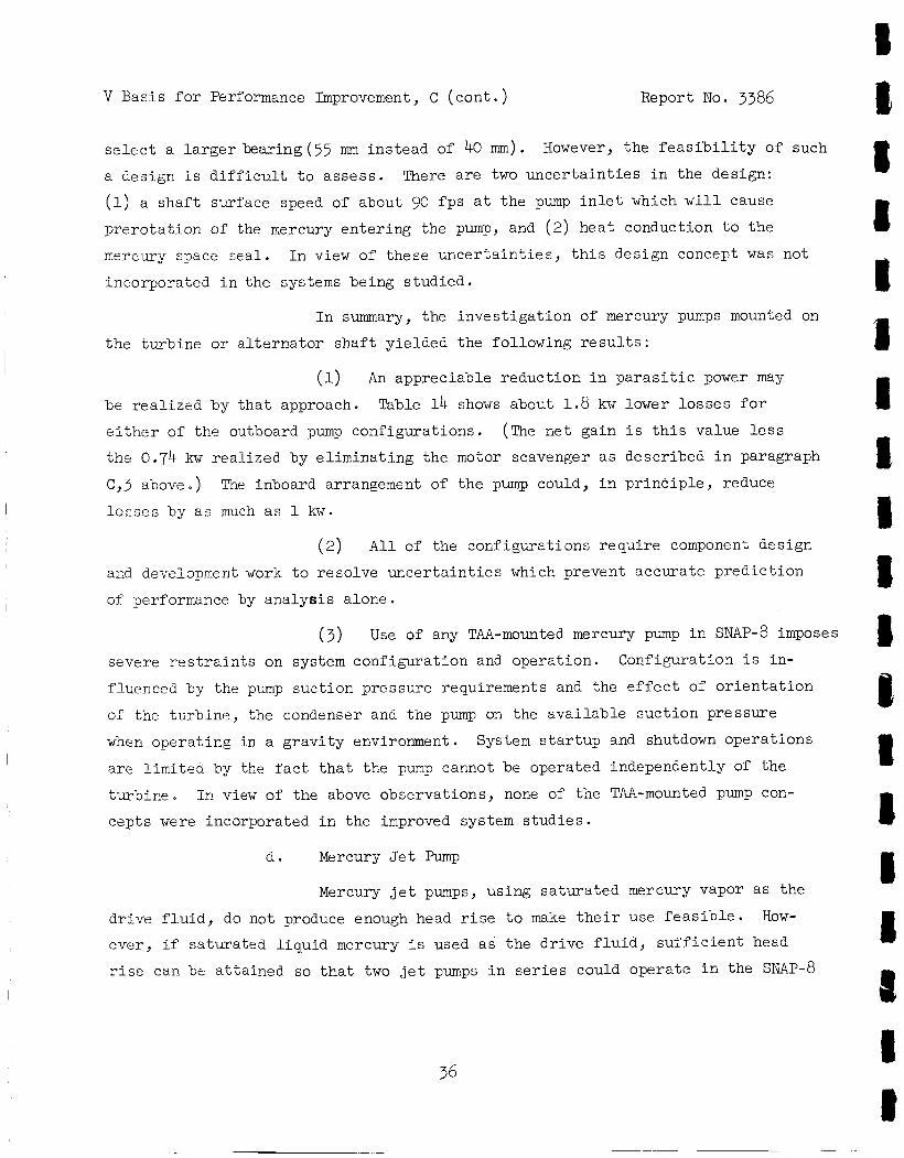
V Basis f o r Performance Improvement, C ( c o n t . ) Report No. 3386
s e l e c t a l a r g e r bearing (55 mm ins tead of 40 mm).
a design i s d i f f i c u l t t o a s ses s . There a r e two u n c e r t a i n t i e s i n the design:
(1) a s h a f t surface speed of about 90 f p s a t the pump i n l e t which w i l l cause
p re ro ta t ion of the mercury en te r ing the pump, and (2 ) hea t conduction t o the
mercury space sea l .
incorporated i n the systems being s tudied .
However, the f e a s i b i l i t y of such
In view of these u n c e r t a i n t i e s , t h i s design concept was not
I n summary, the inves t iga t ion of mercury pumps mounted on
the turbine o r a l t e r n a t o r s h a f t yielded the following r e s u l t s :
(1) An appreciable reduct ion i n p a r a s i t i c power may
Table 14 shows about 1.8 kw lower lo s ses f o r be r ea l i zed by t h a t approach.
e i t h e r of the outboard pump conf igura t ions .
the 0.74 kw r ea l i zed by e l imina t ing the motor scavenger a s descr ibed i n paragraph
C , 3 above.)
l o s s e s by a s much as 1 kw.
(The ne t gain i s t h i s value less
The inboard arrangement of the pump could, i n p r i n c i p l e , reduce
(2) All of the configurat ions requi re component design
ard development work t o reso lve unce r t a in t i e s which prevent accura te p red ic t ion
of performance by ana lys i s a lone.
( 3 ) Use of any TU-mounted mercury pump i n SNAP-8 imposes
severe r e s t r a i n t s on system configurat ion and operat ion.
fluenced by the pump suc t ion pressure requirements and the e f f e c t of o r i e n t a t i o n
of the turb ine , $he condenser and the pump on the ava i l ab le suc t ion pressure
when opera t ing i n a g rav i ty environment.
a r e l imi ted by the f a c t t h a t the pump cannot be operated independently of the
turbir?e. IP view of the above observat ions, none of the TAA-mounted pump con-
cepts were incorporated i n the improved system s tud ie s .
Configuration i s in-
System s t a r t u p and shutdown opera t ions
d . Mercury J e t Pump
Mercury j e t pumps, using sa tu ra t ed mercury vapor a s the
dr ive f l u i d , do not produce enough head r i s e t o make t h e i r use f e a s i b l e .
ever , i f sa tura ted l i q u i d mercury i s used a s the d r ive f l u i d , s u f f i c i e n t head
r i s e ca.r! be a t ta ined so t h a t two j e t pumps i n s e r i e s could operate i n the SNAP-8
How-
36
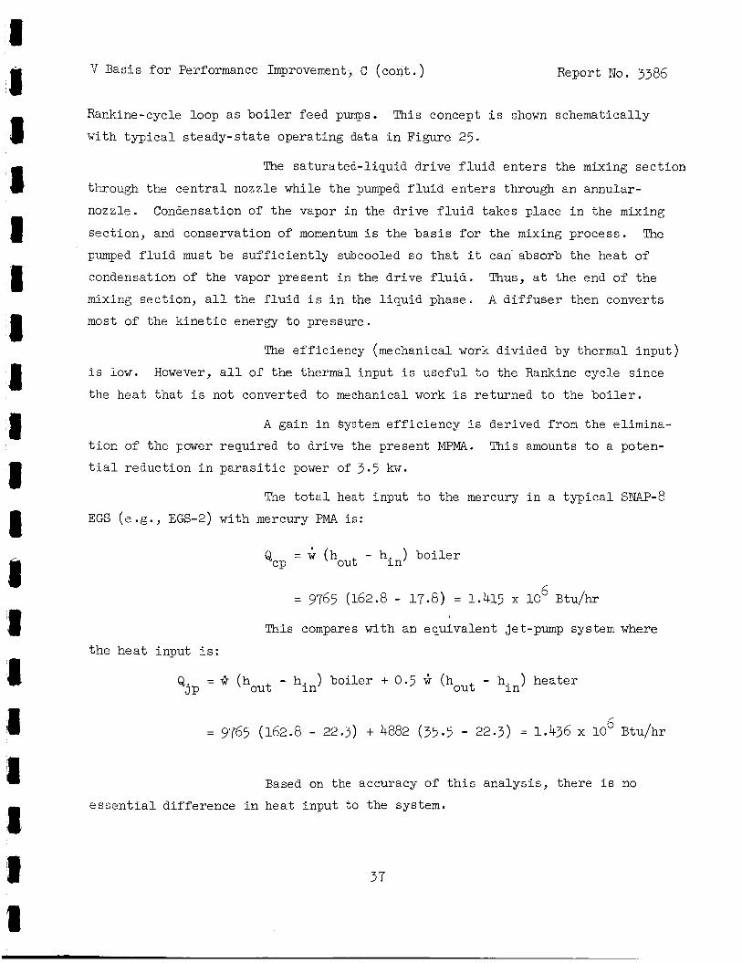
V Basis f o r Performance Improvement, C ( con t . ) Report No. 3386
Rankine-cycle loop a s b o i l e r feed pumps.
with t y p i c a l s teady-s ta te operat ing data i n Figure 25. This concept i s shown schematically
The saturated-l iquid dr ive f l u i d e n t e r s the mixing sec t ion
through the c e n t r a l nozzle while t he pumped f l u i d e n t e r s through an annular-
nozzle. Condensation of the vapor i n the dr ive f l u i d takes place i n the mixing
sec t ion , and conservation of momentum i s the b a s i s f o r the mixing process. The
pmped f l u i d must be s u f f i c i e n t l y subcooled so t h a t i t can- absorb the heat of
condensation of the vapor present i n the d r ive f l u i d . Thus, a t the end of the
mixing sec t ion , a l l the f l u i d i s i n the l i qu id phase. A d i f f u s e r then converts
most of the k i n e t i c energy t o pressure.
The e f f ic iency (mechanical work divided by thermal input )
i s low. However, a l l of the thermal input i s u s e f u l t o the Rankine cycle s ince
the hea t t h a t i s not converted to mechanical work i s returned t o the b o i l e r .
A gain i n System e f f i c i e n c y i s derived from the elimina-
t ior , of the power required t o dr ive the present MPMA. This amounts t o a poten-
t i a l reduct ion i n p a r a s i t i c power of 3.5 kw.
The t o t a l heat input t o the mercury i n a t y p i c a l SNAP-8
EGS ( e .g . , EGS-2) with mercury PMA i s :
- h. ) b o i l e r - Qcp - ' (bout i n
= 9765 (162.8 - 17.8) = 1.415 x 10 6 Btu/hr
This compares with an equivalent jet-pump system where
the hea t input i s :
= G (bout - hin) bo i l e r + 0.5 (bout - h. ) hea te r p i n
6 = 9765 (162.8 - 22.3) + 4882 (35.5 - 22.3) = 1.436 x 10 Btu/hr
Based on the accuracy of t h i s ana lys i s , there i s no
e s s e n t i a l d i f fe rence i n hea t input to the system.
37
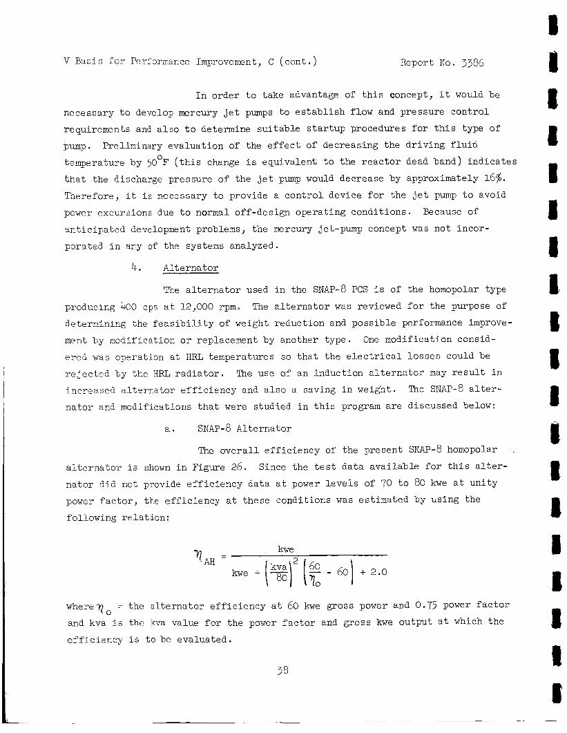
V Basis f o r Performance Improvement, C (cont . ) Report No
I n order t o take advantage of t h i s concept, i t
3386
would be
necessary t o develop mercury j e t pumps t o e s t a b l i s h flow and pressure con t ro l
requirements and a l s o t o determine su i t ab le s t a r t u p procedures f o r t h i s type of
pump. Preliminary eva lua t ion of the e f f e c t of decreasing the driviRg f l u i d
temperature by 50 F ( t h i s change i s equivalent t o the r e a c t o r dead band) ind ica t e s
t h a t the dischazge pressure of the j e t pump would decrease by approximately 16$. Therefore, i t i s Fecessary t o provide a c o n t r o l device f o r the j e t pump t o avoid
power excursions due t o normal off-design opera t ing conditiolls Because of
m t i c i p a t e d development problems, the mercury jet-pump concept was not incor -
porated i n a ry of the systems analyzed.
0
4. Alterna tor
The a l t e r n a t o r used i n the SNAP-8 PCS i s of the homopolar type
The a l t e r n a t o r was reviewed f o r the purpose of producir,g 400 cps a t 12,000 rpm.
determining the f e a s i b i l i t y of weight reduct ion and poss ib l e performance improve-
ment by modification or replacement by another type.
e red was operation a t HRL temperatures so t h a t the e l e c t r i c a l l o s s e s could be
r e j e c t e d by the HRL r a d i a t o r .
increased a l t e r n a t o r e f f i c i e n c y and a l s o a saving i n weight.
i a t o r and modifications t h a t were s tudied i n t h i s program a r e discussed below:
One modif icat ion consid-
The use of an induct ion a l t e r n a t o r may r e s u l t i n
The SNAP-8 a l t e r -
a . SNAP-8 Al te rna tor
The o v e r a l l e f f i c i e n c y of the present SNAP-8 homopolar
a l t e r n a t o r i s shown i n Figure 26. na tor d i d not provide e f f i c i e n c y da ta a t power l e v e l s of 70 t o 80 kwe a t u n i t y
power f a c t o r , the e f f i c i ency a t these condi t ions was est imated by using the
fol lowing r e l a t ion :
Since the t e s t da t a ava i l ab le for t h i s a l t e r -
q,. kwe
wher*To = the a l t e r n a t o r e f f i c i e n c y a t 60 kwe gross power and 0.75 power f a c t o r
and kva is the kva value for the power f a c t o r a rd gross Ime cmtpxt a t :Thick the
e f f i c i e n c y i s t o be evaluated.
38
TJ Basis f o r Performance Improvement, C ( eon t . ) Report No. 3386
This method was used t o es t imate the e f f i c i ency of the
It should be noted t h a t the a l t e r n a t o r design a l t e r n a t o r i n EGS-3 and -6. r a t i n g of 83 kva i s s l i g h t l y exceeded i n these systems. EGS-3 requires 85 kva
c a p a b i l i t y a t 0.92 power f a c t o r and EGS-6 r equ i r e s 86 kva a t a power f a c t o r of
1.0.
nator would increase s ince the ne t power f a c t o r decreases i n the leading d i rec-
t i o n a s more power i s shunted t o the PLR.
amount of capac i t ive reactance i n the c i r c u i t and/or adding induct ive reactance
i n the PLR c i r c g i t . Re-evaluation of the allowable temperature of the ML insu la-
t ior . and the e f f e c t of temperature on the l i f e and r e l i a b i l i t y of t h i s i n s u l a t i o n
may permit operat ion of t h i s component a t the power oJ tput l e v e l s of EGS-3 and -6. This ternperature l i m i t , the power f ac to r v a r i a t i o n with vehicle load, and vol tage
cont ro l l i m i t s , must be evaluated i n more d e t a i l i n f u t u r e s p e c i f i c appl ica t ion
s tud ie s .
If the vehicle load were to drop t o 0 i n EGS-6, the kva load on the a l t e r -
This may be corrected by reducing the
b . Induction Alternator
An evaluat ion w a s made of a c a p a c i t o r - e x i t e d induct ion
generator . This eva lua t ion was prompted by t h e f i c t t h a t the lobed r o t o r uni-
d i r e c t i o n a l flux pr inc ip l e of the homopolar a l t e r n a t o r r e s u l t s i n l e s s than 50%
u t i l i z a t i o n of the output voltage capabi l i ty normally achieved i n machinery of
t h i s s i z e . Since the magnetic c i r c u i t of the induction generator would be u t i -
I.Tzed 100% of the time, ins tead of the 50% u t i l i z a t i o n of the homopolar a l t e rna -
t o r , a s ign i f i can t weight reduct ion i s poss ib le .
Other poter- t ia l advant,ages of the induct ion generator
are t o be expected i n the el iminat ion of the f i e l d c o i l and heavy magnetic yoke
t h a t a r e bas i c t o the homopolar a l t e rna to r , and the reduced l o s s e s from windage
and bearings with the l i g h t e r and smaller r o t o r . An e l e c t r i c a l e f f i c i ency
approaching 95% i s a t t a i n a b l e as a consequence of these reduced e l e c t r i c a l and
mechazical l o s ses e
The induction a l t e r n a t o r , which f ea tu res a s ingle s t a t o r
output winding, s u b s t i t u t e s capacitor e x c i t a t i o n f o r the vol tage regula tor -
e x c i t e r rlow ased. This prel iminary concept would be an open loop regula t ion
39
V Basis f o r Performance Improvement, C ( c o n t . ) Report No. 3386
system using magnetic s a tu ra t ion of the r o t o r i r o n t o s t a b i l i z e the output
vol tage.
t h a t the voltage can be held wi th in - +3.0$ with a - +1.0$ speed va r i a t ion . Addi-
t i o n a l work i s required t o evaluate the problems of vol tage buildup and shor t -
c i r c u i t protect ion .
For a constant power output such a s the SNAP-^ system, i t appears
For the induct ion a l t e r n a t o r t o func t ion properly i n
the SNAP-8 system, the capac i tor -exc i te r must fu rn i sh a leading power f a c t o r under
a l l condi t ions, o r e l s e the a l t e r n a t o r w i l l co l lapse e l e c t r i c a l l y .
po in t f o r t h i s evaluat ion assumes t h a t the worst a l t e r n a t o r load has a 0.75 lagging
power f a c t o r . In order t o co r rec t t h i s t o a 0.75 leading power f a c t o r and, there-
by, provide an ample design margin, a capac i tor with an estimated weight of 50 l b
would be needed t o furn ish the required capac i t ive reactance.
"he design
The e l e c t r i c a l e f f i c i ency of the induction a l t e r n a t o r was
estimated a t 95% with 0.75 leading power f ac to r ; however, the acceptance test
data f o r the homopolar a l t e r n a t o r , from which Figure 26 was p lo t t ed , shows an
o v e r a l l e f f ic iency of 90.7% a t 55 kw and a u n i t y power f a c t o r .
value by deducting the 2.0 kw loss f o r bear ings and s l i n g e r s gives an e l e c t r i c a l
e f f i c i ency of 93 .a$.
Correcting t h i s
It w a s assumed, i n keeping with the replaceable component
concept, t ha t the induct ion a l t e r n a t o r would b o l t t o the TA a s does the present
a l t e r n a t o r , and would contain i t s own bearings, s l i n g e r s , and cool ing j a c k e t .
Preliminary design es tab l i shed r o t o r , s t a t o r , and end-turn dimensions f o r both
a four-pole 12,000 rpm and a two-pole 24,000 rpm machine.
f o r bear ings, s l ingers , end tu rns , and mounting f lange was added t o the r o t o r
s tack length t o obta in o v e r a l l l engths .
1 i n . t o t h e s t a t o r diameter t o allow f o r s t r u c t u r e and cooling j acke t s . With
volumes es tab l i shed , weights were estimated by rat ioFng t o the homopolar a l t e r -
na tor weight and volume.
An allowance of 10 i n .
Diameters were determined by adding
I n making a weight comparison between the two machines,
the induction a l t e rna to r i s charged with the capac i tor -exc i te r u n i t weighing
50 l b . "he dimensions and weights of the two machines a r e compared on Figure 27.
40
V Basis f o r performance Improvement, c (cont . ) Report No. 3386
From t h i s evaluat ion, i t appears t h a t the e l e c t r i c a l e f f i -
ciency of the two machines i s comparable. On a weight b a s i s , the induction a l t e r -
nator i s estimated t o be approximately 175 l b l i g h t e r than the present SNAP-8 a l t e r -
na tor , o r 110 l b l i g h t e r than the weight-reduced a l t e r n a t o r .
of speed con t ro l and e l e c t r i c a l system problems would be needed if the induct ion
a l t e r n a t o r were t o replace the present SNAP-8 a l t e r n a t o r .
was not used i n t@e systems synthesized i n t h i s study.
Addit ional ana lys i s
The induct ion a l t e r n a t o r
e . High-Temperature Al te rna tor
The p o s s i b i l i t y of using a high- temperature ( 4OO0C a l t e rna -
t o r was evaluated a s a means of reducing r a d i a t o r a rea . The high-temperature a l t e r -
na tor would be cooled by HRL NaK, decreasing the heat r e j e c t e d by the L/C r a d i a t o r .
This inves t iga t ion showed t h a t the a l t e r n a t o r e f f i c i ency de-
creased a s the temperature of the winding increased due t o increased r e s i s t i v i t y of
the conductors.
The e f f e c t of high-temperature operat ion on performance a t
1 .0 power f a c t o r i s summarized i n Table 15, showing a drop i n a l t e r n a t o r e f f i c i e n c y
of approximately 2 percentage po in t s .
power f a c t o r .
Somewhat g rea t e r l o s ses r e s u l t a t lower
The e f fec t of s u b s t i t u t i n g t h i s high-temperature a l t e r n a t o r
f o r the L/C cooled a l t e r n a t o r on system performam: w a s analyzed.
decreased by 0.26 percentage po in t s .
20 sq f t due t o the reduced cycle e f f ic iency . An a d d i t i o n a l 1 2 sq f t was required
t o cool the a l t e r n a t o r with HRL NaK so t h a t 39 sq f t were added t o the HRL rad ia-
t o r while 64.5 sq f t were removed from the L/C r a d i a t o r . This r e s u l t s i n a ne t
reduct ion i n t o t a l r a d i a t o r a rea of 32.5 sq f t . These numbers a re based on the
assumption tha t the heat flow t o the L/C cooled and lub r i ca t ed high-temperature
a l t e r n a t o r bearings i s neg l ig ib l e .
d-ice the savings i n r a d i a t o r a rea obtained by using a NaK-cooled a l t e r n a t o r .
System e f f i c i e n c y
This causes the HRL r a d i a t o r t o increase by
Any hea t flow t o these p a r t s would f u r t h e r r e -
Because of the small reduct ion i n r a d i a t o r a rea , the loss
i n e f f i c i ency , and the e f f o r t required t o develop i t , the high-temperature a l t e r -
na tor was not used i n the systems synthesized i n t h i s study.
5-
a l t e r n a t o r output
Speed Control
The SNAP-8 speed control i s a closed-loop system t h a t senses the
frequency, and controls the speed .of the turbine by varying the
41
V Basis f o r Performance Improvement, C (cont . ) Report No. 3386
I
load i n the p a r a s i t i c load r e s i s t o r . The PIX load i s cont ro l led by means of satur-
able r e a c t o r s .
of 1.5 kw i s delivered t o the PLR when the con t ro l i s i n the "off" mode of opera-
t i o n ( i . e . , a t 100s vehicle load ) . I n addi t ion , i n t e r n a l l o s ses i n the sa turab le
r eac to r a re approximately 800 wat t s . The sa turable r eac to r assembly weighs about
190 l b .
The speed i s regulated t o - +l$. With t h i s system, a minimum load
A s i l i con-cont ro l led r e c t i f i e r (SCR) type of speed con t ro l was
evaluated a s a design a l t e r n a t i v e with the expectat ion of reducing the p a r a s i t i c
load on the a l t e r n a t o r . The SCR system i s capable of c u t t i n g of f the power t o
the PLR t o v i r t u a l l y zero when i t i s i n the "off" mode, e l imina t ing the need f o r
1.5 kw r e s i d u a l p a r a s i t i c load . I n addi t ion , the SCR c i r c u i t described below has
an i n t e r n a l power l o s s of only 330 wat t s .
of 1.97 kw i s therefore a t t a i n a b l e by adoption of the SCR speed cont ro l design.
A net r educ t ion ' i n p a r a s i t i c power
A s implif ied schematic diagram of the SCR speed-control system
i s shown i n Figure 28; i t s approximate dimensions a re given i n Figure 29. Paral-
l e l SCR's and diodes are shown i n each phase f o r increased r e l i a b i l i t y s ince each
SCR and diode can ca r ry the current requi red . The current-carrying capab i l i t y i s
a funct ion of the temperature of the SCR. Westinghouse Type 2 N 3888 SCR's and
Ty-pe 1 N 3291 s i l i c o n - r e c t i f i e r diodes were se lec ted as t y p i c a l components for t h i s
cont ro l .
(357OF) f o r the SCR and diodes, respec t ive ly , which allows the assembly t o be
The maximum allowable case temperatures a re 118OC (244'F) and 182OC 1
I; cooled by the L/C f l u i d . With an average cur ren t of 22 amp, the l o s s per diode I
and SCR i s 25 and 30 w a t t s , r espec t ive ly . Consequently, the t o t a l hea t load
t o the L/C loop for the 6 diodes and 6 SCR's i s 330 wa t t s .
The estimated weight of the SCR speed cont ro l i s 40 l b . An
add i t iona l 50 l b f o r l o c a l sh ie ld ing was included i n the weight es t imates f o r
EGS-2 through -6 i n which the SCR cont ro l system was used. This weight of sh ie ld-
ing, cons is t ing of tungsten and l i th ium hydride, i s s u f f i c i e n t t o reduce the r ad i -
a t i o n dose a t the SCR's by one order of magnitude t o lo5 rads gamma and lolo nvt
neutrons. It i s not a t a l l c e r t a i n tha t t h i s supplemental sh ie ld ing i s necessary;
however, s ince the SCR's a re somewhat more s e n t i t i v e t o r a d i a t i o n than the diodes
and the o ther e l ec t ron ic components, the sh ie ld ing w a s added a s a precaut ion.
42
v Basis f o r Performance Improvement, c (cont . )
6. Boi le r
Report No. 3386
The SNU-8 b o i l e r i s a single-pass counter-flow design i n
which seven p a r a l l e l tubes containing mercury a re enclosed i n a s ing le tube
containing MaK. The c h a r a c t e r i s t i c temperature p r o f i l e of t h i s type of b o i l e r
i s such t h a t the mercury and NaK temperatures approach the same value a t a po in t
where i n i t i a l mercury bo i l ing occurs, about 10% along the tube from the mercury
i n l e t end. This loca t ion has been referred t o as the "pinch-point". The NaK-
mercury temperature d i f fe rence a t the pinch-point (AT ) i s an important param-
e t e r a f f e c t i r g system performance.
In s.Libseqdent paragraphs, o ther bo i l e r performance c h a r a c t e r i s t i c s and t h e i r
trestment 111 the system s tudies a re described.
P This i s discussed i n the following paragraph.
a . Boi ler Pressure S t a b i l i t y
Boi ler pressure s t a b i l i t y , expressed a s the r a t i o of
pressure f luc tua t ion t o the absolute pressure a t the b o i l e r mercury o u t l e t , i s
shown i n Figure 30 a s a funct ion of AT The curves a r e based on b o i l e r t e s t P
da ta and show t h a t pressure osc i l l a t ions increase as AT decreases. The pressure
o s c i l l a t i o n s occur a t a frequency of 0.2 t o 0.5 cps, low enough t h a t the turbine
output power w i l l f l uc tua t e correspondingly a t approximately the same amplitude
( i n %)
P
From the data on which Figure 30 i s based, a minimum
AT
b a s i s , the b o i l e r pressure f luc tua t ion w i l l not exceed - +3%. c r i t e r i o n t o the system performance calculat ions i n the present study, a AT of
75'F was used because a l l of the systems were computed f o r the upper temperature
l i m i t (133OOF) of the reac tor coolant. I f the lower temperature l i m i t (128OOF)
were 'used, the AT would be 25'F since the temperatures i n the primary NaK loop
would be urriformly 50' lower, while the temperatures i n the mercury loop would
be subs t an t i a l ly unchanged. This approach assures t h a t the systems compared i n
the study are capable of operat ing s tably a t the lower temperature condi t ion of
the r e a c t o r coolant.
of 250°F was chosen a s the l imit ing c r i t e r i o n f o r b o i l e r operation; on t h i s P
I n applying t h i s
P
P
43
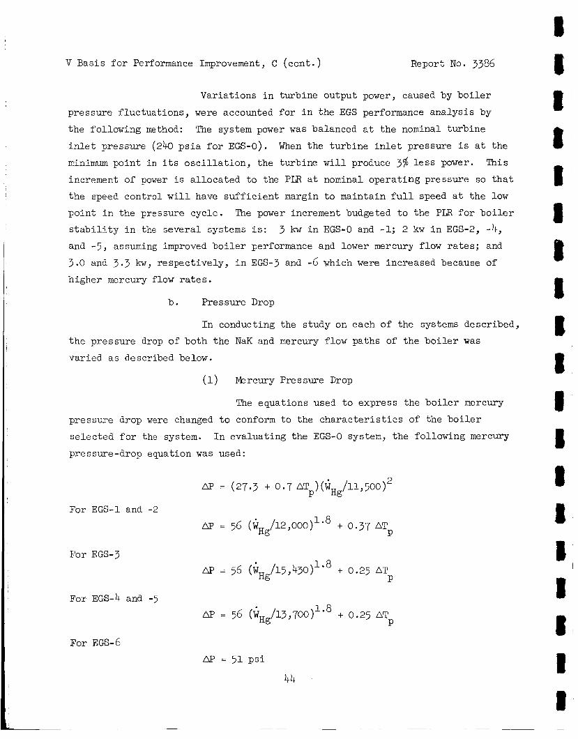
V Basis f o r Performance Improvement, C (cont . ) Report No. 3386
Variat ions i n turbine output power, caused by b o i l e r
pressure f luc tua t ions , were accounted for i n the EGS performance ana lys i s by
the following method:
i n l e t pressure (240 p s i a f o r EGS-0).
minimum point i n i t s o s c i l l a t i o n , the turbine w i l l produce 37% l e s s power.
increment of power is a l loca ted t o the PIX a t nominal opera t ing pressure so t h a t
the speed control w i l l have s u f f i c i e n t margin t o maintain f u l l speed a t the l o w
point i n the pressure cycle . The power increment budgeted t o the PLR f o r b o i l e r
s t a b i l i t y i n the several systems is : 3 kw i n EGS-0 and -1; 2 kw i n EGS-2, -4, and -5, assuming improved b o i l e r performance and lower mercury flow ra t e s ; and
3.0 and 3.3 kw, respect ively, i n EGS-3 and -6 which were increased because of
higher mercury flow r a t e s .
The system power was balanced a t the nominal turbine
When the turb ine i n l e t pressure i s a t the
This
b . Pressure Drop
I n conducting the study on each of the systems described,
the pressure drop of both the NaK and mercury flow paths of the b o i l e r was
varied a s described below.
(1) Mercury Pressure Drop
The equations used t o express the b o i l e r mercury
pressure drop were changed t o conform t o the c h a r a c t e r i s t i c s of the b o i l e r
se lec ted f o r the system. I n evaluat ing the EGS-0 system, the following mercury
pressure-drop equation was used:
AF' = (27.3 + 0.7 AT )(i /11,500)2 P Hg
/12,000)1'8 + 0.37 AT Hg P
For EGS-1 and -2
AP = 56 (i
For EGS-3
AP = 56 (4 /15,43O)lo8 + 0.25 AT Hg P
For EGS-4 and -5 AP = 56 (4Hg/13,700)1'8 + 0.25 AT
P
For EGS-6
L1p = 51 p s i
44
V Basis f o r Performance Improvement, C (cont . ) Report No. 3386
I n each of these equations W
the AT a t the mercury pinch-point.
i n temperature between the mercury and the NaK a t the poin t i n the b o i l e r where
b o i l i n g s t a r t s .
i s the mercury flow r a t e i n lb /hr , and AT i s
Pinch point i s defined a s the d i f fe rence Hg P
The equation given for mercury AP f o r EGS-0 w a s
obtained from the tube-in-tube b o i l e r design ana lys i s while the equation f o r
mercury AP used i n EGS-1 and -2 was obtained empir ical ly from tes t da ta on the
tube-in-ttibe b o i l e r , and, therefore , represented the a c t u a l measured mercury
pressure drops f o r the 7-tube mercury b o i l e r .
r a t e compatible with 600 kw input f rom the r e a c t o r made it necessary t o increase
the number of mercury tubes t o nine.
ized f o r nine tubes a t the same mercury flow per tube and the AT
was reduced on the assumption of a p o t e n t i a l improvement i n b o i l e r plug design.
I n EGS-L and -5> the turbine i n l e t pressure was increased from 240 to 350 ps i a .
This chmge resu l ted i n modification of the mercury Ap equation t o account f o r
the e f f e c t of the change i n mercury vapor densi ty on the pressure drop. For EGS-6, i t was assumed t h a t a b o i l e r with 51 pounds AP could be designed when
the mercury flow r a t e i s 14,000 lb/hr.
I n EGS-3, a higher mercury flow
The W term i n the AP equat ion was normal-
coef f ic ien t P
( 2) NaK Pres sure Drop
I n EGS-0, the b o i l e r NaK-tube I D was 4.0 inches
while the EGS-1 and -2 b o i l e r was reduced i n NaK-tube I D so t h a t m a x i m u m
weight reduct ion could be achieved. The reduced NaK-tube I D i s 3.375 inches
which increases the b o i l e r NaK A€' f r o m 1.5 t o 8.1 p s i a t 48,100 lb /hr .
reduced NaK flow r a t e s f o r EGS-1 and -2 r e s u l t i n NaK AP of 5.6 and 4.3 p s i ,
respec5ively. The NaK tube f o r the EGS-3 b o i l e r was increased t o give the same
Na.K v e l o c i t i e s as i n the o r i g i n a l bo i le r ; the NaKAP i n t h i s b o i l e r i s 1.55 p s i
a t 49,000 lb/hr .
The
Since the s t a t e po in ts were changed for the remain-
ing systems, it was necessary t o consider the e f f e c t of these s t a t e - p o i n t changes
on b o i l e r design requirements. I n a l l b o i l e r s used i n t h i s study, a constant
AT
band system operat ing condi t ion. .
v a l w of 75'F was used f o r the upper temperature l i m i t of the reac tor dead- P
45
V Basis f o r Performance Improvement, C ( c a n t . ) Report No. 3386
A s tu rb ine i n l e t pressure increases , the mercury
b o i l i n g temperature a t the poin t where b o i l i n g commences a l s o increases .
the r e a c t o r o u t l e t temperature i s constant , and a constant value of 75 AT i s
required, the NaK flow r a t e i n the primary loop must increase a s the turb ine in-
l e t pressure increases . Figure 31 shows the r a t i o of primary NaK flow r a t e t o
mercury flow ra te a s a func t ion of turbine i n l e t p ressure . Because of t h i s
r e l a t i o n , the NaK tube diameter of the b o i l e r s f o r the remaining systems was
increased t o reduce the NaK pressure drop.
b o i l e r was used; for EGS-6, the I D was increased t o maintain the same NaK v e l o c i t y
a s i n the EGS-0 b o i l e r .
b o i l e r s used i n the var ious systems.
Since
P 0
For EGS-4 and -5, the I D of the EGS-0
Table 16 l i s t s the phys ica l c h a r a c t e r i s t i c s of the
C . Boi le r Mater ia ls
The present SNAP-8 b o i l e r uses 316 s t a i n l e s s s t e e l f o r
the NaK tube and 9Cr-lMo s t e e l tubes f o r the mercury. A t p resent , there i s con-
s iderable e f f o r t being expended on the development of ma te r i a l f o r the mercury
tubes which has higher s t r eng th and corrosion r e s i s t ance a t opera t ing tempera-
t u r e . The performance p o t e n t i a l study has been based on the assumption t h a t
su i t ab le mater ia ls w i l l be ava i l ab le f o r use i n b o i l e r s where the pressures have
been increased to meet the s t a t e -po in t requirements f o r EGS-4, -5, and -6.
7. E l e c t r i c a l Sys tem
The a l t e r n a t o r e f f i c i e n c y i s a func t ion of the power f a c t o r
of the t o t a l a l t e r n a t o r load and the gross power output , a s shown i n Figure 26. The t o t a l a l t e r n a t o r load i s made up of the fol lowing: vehic le load, primary
NaK PMA, mercury PMA, HRL NaK PMA, L/C PMA, SCR speed cont ro l , vol tage cont ro l ,
PLB s t a b i l i t y allowance , and r eac to r con t ro l s .
By adding the kvar values and the kw values of each load, the
t o t a l kva load on the a l t e r n a t o r i s obtained by taking the square r o o t of the
sum of the squares of kvar and kw.
the a l t e r n a t o r load power f a c t o r .
therefore , a function of the vector sum of a l l the loads on the a l t e r n a t o r .
The gross kw divided by the kva then gives
The amount of power f a c t o r co r rec t ion i s ,
46
I 8 I t I 8 B I 1 I I I 8 I I I I f I
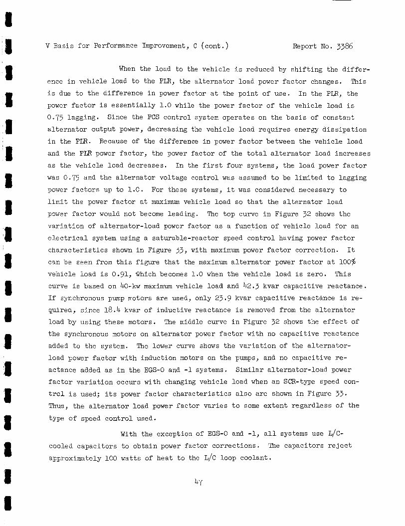
V Basis f o r Performance Improvement , C (cont . ) Report No. 3386
1 3 8 3 1
When the load t o the vehic le i s reduced by s h i f t i n g the d i f f e r -
ence i n vehic le load t o the PLR, the a l t e r n a t o r load power f a c t o r changes. This
i s due t o the d i f fe rence i n power fac tor a t the poin t of use. I n the PLR, the
power f a c t o r i s e s s e n t i a l l y 1.0 while the power f a c t o r of the vehicle load i s
0.75 lagging. Since the PCS cont ro l system opera tes on the b a s i s of constant
a l t e r n a t o r output power, decreasing the vehic le load r equ i r e s energy d i s s i p a t i o n
i n the PLR. Because of the difference i n power f a c t o r between the vehic le load
and the PLR power f a c t o r , the power f a c t o r of the t o t a l a l t e r n a t o r load increases
a s the vehic le load decreases . I n the f i r s t fou r systems, the load power f a c t o r
was 0.75 and the a l t e r n a t o r voltage cont ro l was assumed t o be l imi t ed t o lagging
power f a c t o r s up t o 1.0. For these systems, i t was considered necessary t o
l i m i t the power f a c t o r a t m a x i m u m vehicle load so t h a t the a l t e r n a t o r load
power f a c t o r would not become leading. The top curve i n Figure 32 shows the
v a r i a t t o n of a l t e rna to r - load power f a c t o r a s a func t ion of vehicle load f o r an
e l e c t r i c a l system using a sa turab le- reac tor speed con t ro l having power f a c t o r
c h a r a c t e r i s t i c s shown i n Figure 33, with maximum power f a c t o r cor rec t ion . It
can be seen from t h i s f i g u r e tha t the maximum a l t e r n a t o r power f a c t o r a t 100%
vehic le load i s 0.91, Ghich becomes 1.0 when the vehic le load i s zero. This
curve i s based on 40-kw m a x i m u m vehicle load and 42.3 kvar capac i t ive reactance.
I f synchronous pump motors a re used, only 23.9 kvar capac i t ive reactance i s re -
quired, s ince 18.4 kvar of inductive reactance i s removed from the a l t e r n a t o r
Load by using these motors. The middle curve i n Figure 32 shows the e f f e c t of
the synchronous motors on a l t e r n a t o r power f a c t o r with no capac i t ive reactance
added t o the system. The lower curve shows the v a r i a t i o n of the a l t e r n a t o r -
load power f a c t o r with induct ion motors on the pumps, and no capac i t ive re-
actance added as i n the EGS-0 and -1 systems.
f a c t o r v a r i a t i o n occurs with changing vehic le load when a n SCR-type speed con-
t r o l i s used; i t s power f a c t o r c h a r a c t e r i s t i c s a l s o a r e shown i n Figure 33. Thus, the a l t e r n a t o r load power f ac to r v a r i e s t o some ex ten t regard less of the
type of speed con t ro l used.
Similar a l t e rna to r - load power
With the exception of EGS-0 and -1, a l l systems use L/C-
cooled capac i to r s t o obta in power f ac to r co r rec t ions . The capac i tors r e j e c t
approximately 100 wat t s of hea t t o the L/C loop coolant .
47
Report No. 3386 V Basis f o r Performance Improvement, C ( c o n t . )
During the course of the performance p o t e n t i a l study, it w a s
learned t h a t the a l t e r n a t o r vol tage con t ro l would operate down t o 0.92 leading
power f a c t o r a t a gross output of 60 kwe.
determined by the vol tage r egu la to r c h a r a c t e r i s t i c s which r e s u l t i n increas ing
output vol tage when the power f a c t o r decreases i n the lead ing d i r e c t i o n .
lagging power fac tor i s l imi t ed by the temperature r i s e of the a l t e r n a t o r wind-
ings and i s , therefore , a func t ion of the gross kw output of the a l t e r n a t o r .
A t 55 h e , which i s representa t ive of those systems t h a t produce 40 kwe n e t
power, the lowest a l t e rna to r - load power f a c t o r i s 0.66 lagging. This l i m i t
i s e s t ab l i shed by the maximum temperature r i s e of the a l t e r n a t o r windings
commensurate with in su la t ion l i f e and r e l i a b i l i t y . The vehicle- load power
f a c t o r a l s o was increased from 0.75 lagging t o 0.85 lagging which reduces the
e f f e c t of changing vehicle load on the ne t a l t e r n a t o r power f a c t o r . A s a re- s u l t of these input changes, the system performance of EGS-4, -5, and -6 have
been evaluated a t a ne t a l t e r n a t o r power f a c t o r of 1.0 a t f u l l vehic le load .
The leading power f a c t o r l i m i t i s
The
Table 17 gives the capac i t ive reactance required f o r each
EGS where the power f a c t o r of the a l t e r n a t o r has been cor rec ted .
s en ta t ive example, a 42.3 kvar condenser assembly w i l l weigh approximately
25 lb and have dimensions of 8 x 8 x 9 inches, i f made up a s a s ing le assembly.
There i s an advantage, however, i n making the power f a c t o r cor rec t ions a t each
load .
corrected loca l ly , t h i s w i l l e i t h e r reduce the s t a r t u p b a t t e r y and i n v e r t e r
requirements, or provide b e t t e r motor s t a r t u p torque. Also, by co r rec t ing
the power f a c t o r of each ind iv idua l load, a t the load, the ne t power f a c t o r
of the a l t e r n a t o r w i l l not be a f f ec t ed a s much by the changing vehicle load .
These considerat ions should be evaluated i n more d e t a i l for any s p e c i f i c
app l i ca t ion .
A s a repre-
For example, if the power f a c t o r of the ind iv idua l pump motors i s
8. Components Not Modified
In t h i s s ec t ion , the components a r e noted which were reviewed
f o r poss ib le performance improvement b u t not modified. Modifications here
imply a change i n performance c h a r a c t e r i s t i c s and do not include changes made
48
I ~I t I I I I 'I '1 ,I
V Basis for Performance Improvement, C ( c o n t . ) Report No. 3386
i n a component which may be required for changes i n flow r a t e . Components
which have not been changed i n c h a r a c t e r i s t i c s a r e : mercury condenser; a l t e r -
nator ; mercury PMA; s t a r t u p components, such a s b a t t e r i e s and inve r t e r ; e l e c -
t r i c a l components, such a s 'voltage control , sequencer, vehic le load switch,
power t ransmission cable , and PIB; valves, such a s the mercury f low-control
valve, NaK temperature-control valve, a u x i l i a r y NaK star tup-loop shutoff valve,
and L/C loop shutof f valves; mercury i n j e c t i o n system; expansion r e se rvo i r s ;
a rd L/C PMA. I n EGS-3 and -6, the mercury condenser was changed i n s i z e only
t o accommodate the increased mercury flow r a t e s . The number of mercury tubes
was incrsased from 73 t o 85 tubes.
The a l t e r n a t o r was found t o have s u f f i c i e n t power output
c a p a b i l i t y when the load power f ac to r w a s increased f o r most of the systems;
poss ib le exceptions were EGS-3 and -6. t o r s t e s t e d ind ica ted a m a x i m u m kva range of 83 t o 89 before the end-turn
temperatures exceeded the 200 C l i m i t a t i o n imposed by the ML organic insu la-
t i o n used i n t h i s component.
The d i f f e rences i n ind iv idua l a l t e rna -
0
The mercury PMA was found t o have ample head r i s e f o r a l l
systems s tudied even when turbine i n l e t p ressures of 400 p s i a a r e used. How-
ever , the motor scavenger s l i n g e r was removed f o r EGS-4, -5, and -6 t o reduce
t h e pump motor input power requirement.
S t a r tup components, such a s b a t t e r i e s and the inve r t e r , were
not changed. The performance p o t e n t i a l study was l imi t ed t o improvements i n
s t eady- s t a t e performance of the SNAP-8 EG systems so t h a t s t a r t u p procedures
and improvements were not included i n t h i s study.
The vol tage control , s t a r t programmer, vehic le load switch,
power buss, and the PLB were considered s a t i s f a c t o r y f o r a l l systems s tudied .
There a r e some condi t ions of operation which may make i t des i r ab le t o improve
the vol tage con t ro l so t h a t the output voltage of the a l t e r n a t o r w i l l remain
w i t h i n spec i f ied l i m i t s over a grea te r lead ing power-factor range. However,
the amount of power f a c t o r correct ion, and the manner i n which it i s appl ied,
may make t h i s unnecessary.
N a K loop t o the ER NaK loop i n EGS-4, -5, and -6. ope ra t ing temperature of the res i s tance elements and increases the r e l i a b i l i t y
The loca t ion of the PL;R was changed from the primary
This change reduces the
49
V Basis f o r Performance Improvement, C (cont . ) Report No. 3386
and l i f e of t h i s component.
HRL NaK rad ia to r a r ea .
The penal ty for t h i s i s 4 t o 7 sq f t of a d d i t i o n a l
The valves used i n the SNAP-8 PCS a re re ta ined for a l l of
the systems analyzed f o r performance i n t h i s s tudy.
The MIS concept has been r e t a ined and the only changes made
were i n capacity. The m r c u r y inventory of the var ious EG systems changes so
t h a t the MIS reservoi r must be changed.
Expansion r e s e r v o i r s for the NaK and L/C loops w i l l vary i n
capac i ty requirements i n proport ion t o the r e spec t ive loop inventory v a r i a t i o n s .
The b a s i c design concept f o r these components was no t changed But the weights
of these components were changed i n accordance w i t h the loop inventor ies f o r
each of the EG systems s tudied .
The L/C PMA was considered s a t i s f a c t o r y f o r a l l systems
s tudied .
D. IMPROVEMENT BY SYSTEM MODIFICATIONS
I n addi t ion t o changes i n component c h a r a c t e r i s t i c s , the e f f e c t of
s t a t e -po in t changes i n the mercury loop and o the r system changes on o v e r a l l
system performance w a s evaluated f o r app l i ca t ion t o EGS-4, -5, and -6. The
Rankine-cycle e f f i c i ency and, therefore , the o v e r a l l system e f f i c i e n c y increases
with turb ine pressure r a t i o increase . The purpose of t h i s p a r t of the study was
t o determine whether any worthwhile performance improvement could be r e a l i z e d
by opera t ing a t new turb ine i n l e t and e x i t p ressures (but without changing the
m a x i m u m system temperature of 1300 F nominal a t the r eac to r o u t l e t ) . A secon-
dary and r e l a t ed purpose of the ana lys i s was concerned with reducing r a d i a t o r
a r ea by increasing e f f e c t i v e r a d i a t i n g temperature.
c a l c u l a t i n g r ad ia to r a r ea f o r d i f f e r e n t values of temperature drop through the
r a d i a t o r a t severa l s t a t e -po in t s . I n summary, i t was found t h a t s~Ap-8 performance could be improved by ad jus t ing the turb ine i n l e t p ressure , bu t
t h i s i s f eas ib l e only i n conjunction wi th o the r improvements; i .e . , component
0
This was evaluated by
50
g I I 8 8 I 8 I I II 8 1 8 8 1 8 8 I 1
V Bas is f o r Performance Improvement, D ( con t . ) Report No. 3386
modif icat ions previously discussed
-5, and -6 a r e compared with those used i n EGS-0 a s fol lows:
The s t a t e -po in t s se lec ted f o r use i n EGS-4,
Turbine i n l e t pressure, p s i a
Turbine e x i t pressure, p s i a
Radiator NaKAT, F 0
EGS-0 EGS-4, -5, -6
350 240 14.5 14.5
150 1 72
1. Scope of the S ta tepoin t A n a l y e
The s t a t e p o i n t ana lys i s comprised a s e r i e s of s teady-s ta te
computsr runs i n which turbine i n l e t and e x i t p ressures and HRL r a d i a t o r temper-
a t u r e drop were var ied independently.
the e f f e c t of these va r i ab le s on SNAP-8 system performance.
were made with output power f ixed a t 40 kwe. However, a few runs were a l s o made
with input ( r e a c t o r ) power f ixed a t 600 kwt t o determine whether the same s t a t e -
po in t s would be s a t i s f a c t o r y a t the higher power condi t ion. Turbine i n l e t pres-
s w e w a s var ied from 250 t o 450 ps ia , e x i t pressure from 8.5 t o 32.5 ps i a and
HRL r a d i a t o r AT from 100 t o 2OO0F. Other considerat ions accounted f o r i n the
a n a l y s i s regarding component c h a r a c t e r i s t i c s a r e described i n the following
paragraphs.
Over bC computer runs were made t o show
Most of the runs
a . Treatment of Turbine Eff ic iency
Since turbine e f f i c i e n c y i s inf luenced by the pressure
r a t i o across the turbine and s ince the pressure r a t i o var ied from 8 t o 53 over
the range of pressures covered, i t was necessary t o develop a turb ine e f f i c i ency /
pressure r a t i o func t ion f o r use i n the ana lys i s . A t the higher pressure r a t i o s ,
tu rb ine e f f i c i ency i s reduced a s a r e s u l t of reduced a r c of admission i n the
f i r s t t w o s tages and increased d isk lo s ses a t higher s tage pressures . The tu r - b ine e f f i c i e c c y c h a r a c t e r i s t i c developed f o r the s t a t e p o i n t ana lys i s i s shown i n
Figure 34. EGS-4, -5, and -6. t i onsh ip
These values a r e a l s o used i n the system performance ana lys i s f o r
Appendix C descr ibes i n d e t a i l the development of this rela-
V Basis f o r Performance Improvement, D ( c o n t . ) Report No. 3386
b. HRL Radiator Temperature Conditions
The temperature of the NaK en te r ing the HRL r a d i a t o r v a r i e s
as the turbine e x i t pressure inc reases . A t h igher turbine e x i t pressures the con-
densing temperature i s higher , corresponding t o mercury sa tu ra t ion condi t ions.
The temperature of the NaK leaving the condenser i s r e l a t e d t o the condensing
temperature.
condensing temperature aFd the NaK temperature en te r ing the r a d i a t o r was assumed.
Therefore, increasing the tu rb ine ex i t pressure automatical ly inc reases the e f f ec -
t i v e r a d i a t o r temperature, thereby reducing r a d i a t o r a r e a . The r e l a t i o n s h i p be-
tween turbine e x i t pressure and NaK temperature e n t e r i n g the r a d i a t o r was as
follows :
0 For purposes of t h i s ana lys i s , a drop of 10 F between the mercury
Turbine E x i t Pressure Radiator I n l e t Tempe r a t ure F 0 p s i a
8.5 607
20.5 696 26.5 724 32.5 748
14.5 660
The temperature drop across the r a d i a t o r was varied independently f o r each con-
d i t i o n of turbine e x i t pressure t o explore optimum r a d i a t o r a r ea f o r each e x i t
pressure a
c . Other Component C h a r a c t e r i s t i c s Used i n the State-point Analysis
(1) Lube/Coolant r a d i a t o r temperature were held constant
a t 243OF i n and 210°F ou t .
( 2 ) Temperature leaving the r eac to r was maintained a t
1330°F. allowing f o r a small hea t loss from the p ipe .
The temperature e n t e r i n g the b o i l e r i s only one o r two degrees less ,
(3) The b o i l e r pressure drop was defined by the follow-
i n g equation which was l a t e r used for EGS-4 and -5 as we l l :
52
I I 8 3 I I 8 I 8 8 1 I D 8 8 8 8
1 e
I 8 1 II 8 I 8 8
V Basis f o r Performance Improvement, D ( con t . ) Report No. 3386
(4) The pinch-point temperature difference i n the 0 b o i l e r was maintained a t 75 F. This means t h a t a s tu rb ine i n l e t pressure increased,
mercury b o i l i n g pressure increased, and hence the mercury temperature i n the b o i l e r
a t the pinch-point. This, i n t u rn , required an increase i n the NaK temperature i n
the b o i l e r a t the pinch-point. Since the temperature en te r ing the b o i l e r was
e s s e n t i a l l y constant , the temperature drop of NaK i n the b o i l e r then decreased,
and the NaK flow r a t e increased i n order t o t r a n s f e r the required hea t r a t e .
HeDce the NaK flow r a t e i n the primary loop w a s s ens i t i ve t o the turb ine i n l e t
p ressure and, i n f a c t , l imi t ed the m a x i m u m tu rb ine i n l e t pressure which could be
considered
( 5 ) For the two NaK PMA' s i t was found necessary t o
"customize" the pumps and t o reduce loop pressure drop i n order t o meet the wide
v a r i a t i o n i n flow r a t e s i n the PNL and HRL. The NaK PMA c h a r a c t e r i s t i c s used
were very s imi l a r bu t not i d e n t i c a l t o those shown i n Figure 21. Loop pressure
drop data a r e discussed f u r t h e r i n paragraph 2 .b . (3) , below.
d . I n general , the systems character ized i n the s t a t e p o i n t
ana lys i s approximate, b u t do not match p rec i se ly , the condi t ions t h a t were l a t e r
def ined i n charac te r iz ing EGS-4.
cha rac t e r i ze any p a r t i c u l a r system b u t t o provide a b a s i s f o r eva lua t ing the
e f f e c t s of the se lec ted independent va r i ab le s .
However, the purpose of the ana lys i s was not t o
2 . Resul ts of State-Point Analysis
a . Discussion of Resul ts
The r e s u l t s of the s t a t e -po in t ana lys i s a r e shown i n
Figures 35 and 36. Figure 35 shows the v a r i a t i o n of r e a c t o r input power, t o t a l
r a d i a t o r a r ea , p a r a s i t i c load, Rankine-cycle e f f i c i ency , and o v e r a l l system e f f i -
ciency with turb ine i n l e t pressure f o r a constant ne t output of 40 h e , r a d i a t o r
NaK AT of 150°F , and L/C r a d i a t o r AT of 33OF.
The t o t a l r ad ia to r a r ea curves include both the HRL radi-
a t o r and L/C r a d i a t o r a r eas .
occurs a t a tu rb ine i n l e t pressure of 400 p s i a , the minimum r a d i a t o r a r ea i s
reached a t a tu rb ine exhaust pressure of 26.5 psia; however, exhaust pressures
Of 20.5 and 32.5 ps i a a l s o r e s u l t i n very near the minimum t o t a l r a d i a t o r a r ea .
The r e s u l t s i n d i c a t e t h a t minimum r a d i a t o r a rea
53
V Basis f o r Performance Improvement, D ( con t . ) Report No. 3386
The curves of p a r a s i t i c power i n Figure 35 r i s e sharply a s
tu rb ice i n l e t pressure increases above 400 p s i a .
demand by the primary NaK PMA corresponding t o increas ing NaK flow r a t e s . NaK
This i s due t o increas ing power
54
0 flow m m t increase a s turbine i n l e t p ressure r i s e s i n order t o maintain a 75 F
pinch-point AT i n the b o i l e r . For example, a t 350 p s i a tu rb ine i n l e t p ressure
and 14.5 p s i a e x i t p ressure , the primary NaK flow i s 44,100 lb /hr ; a t 450 and
14.5 ps i a turbine pressures , the NaK flow i s 68,400 l b / h r .
i l l u s t r a t e d i n Figure 31. Flow rates i n the mercury loop and hea t r e j e c t i o n
loop a re v i r t o a l l y ucchanged over t h i s same range of condi t ions .
tu rb ine e x i t pressures , the increase i n p a r a s i t i c power i s more pronounced be-
CSUSP f low r a t e s i n a l l loops a re higher , r e f l e c t i n g lower o v e r a l l e f f i c i e n c i e s .
This e f f e c t a l s o i s
A t the h igher
The Rankine-cycle e f f i c i e n c y curves a r e a d i r e c t r e s u l t
of the i x r e a s e d ava i l ab le energy due t o the higher tu rb ine pressure r a t i o s .
Overal l system e f f i c i e n c i e s tend t o fol low the t rend i n Rankine-cycle e f f i c i e n c i e s
u E t i l the p a r a s i t i c load increases a t the higher tu rb ine i n l e t p ressures causes
a drop.
ciency i s zear ly constant a t tu rb ine i n l e t p ressures ranging from 350 t o 450 p s i a .
For a turbine exhaust pressure of 1 4 . 5 p s i a , the o v e r a l l system e f f i -
Another independent parameter i n determining system per-
formance, and p a r t i c u l a r l y the H3L r a d i a t o r a rea , i s the NaK AT i n the r a d i a t o r . 0 Valkes of RaK AT considered were 100, 125, 150, and 175 F. Decreasing the NaK
AT incPeases the average HBL r a d i a t o r temperAture and thus decreases i t s s i z e .
Figure 36 shows the e f f e c t of NaK r a d i a t o r AT on t o t a l r a d i a t o r a r e a . Included
ir! th i s 'curve i s a l i n e def in ing the reg ion of NPSH d i f f i c u l t i e s . A s the AT of
tbe r a d i a t o r decreases, the amount of subcooling of the mercury decreases which
reduces the NPSE ava i lab le a t the MPMA. To avoid NPSH problems, i t i s necessary
t o operate a t turbine exhaust pressures and NaK r a d i a t o r AT values which a r e i n
the region below the marginal NPSH l i n e .
The t o t a l r a d i a t o r a rea appears t o be a l i n e a r func t ion
of NaK r a d i a t o r AT a t constant t w b i n e back pressure u n t i l NaK AT values of
125 F a r e reached. Below t h i s value, the HRL NaK flow r a t e s increase s u f f i -
c i e n t l y t o make the HRPMA pumping power requirements s t a r t i nc reas ing the mercury
0
I I I 8 1 I I 8 8 8 8 8 I I 8 8 8 I 1
8 8 1 1 8 1 8 .D 8 8 I 8 1 I 8 88 8 3 8
V Bas is f o r Performance Improvement, D ( con t . ) Report No. 3386
flow r a t e s t o supply the necessary addi t iona l pumping power.
l e v e l i n g o f f of r a d i a t o r a r ea reduction f o r values of NaK r a d i a t o r AT of 100°F
or l e s s .
This resu l t s i n a
For a turbine back pressure of 14.5 ps i a , the minimum
r a d i a t o r NaK AT i s 150°F which i s es tab l i shed by NPSH cons idera t ions .
s u l t s i n a t o t a l r a d i a t o r a r ea of about 990 sq f t .
b ine exhaust pressures , a reduct ion i n t o t a l r a d i a t o r a r ea r e s u l t s from the
hi.gher r a d i a t o r i n l e t temperatures and the NPSH l i m i t a t i o n allows the r ad ia to r
NaK AT t o be reduced t o 100°F.
This r e -
For 20.5 and 26.5 ps ia tur -
This combination r e s u l t s i n a t o t a l r a d i a t o r
a r ea of about 9 0 sq f t or a t o t a l reduction of about 9.1 percent .
b . Component E f fec t s
(1) Mercury Pump NPSH
The NPSH requirement of the present MPMA l i m i t s
the tzzj_.bine e x i t pressure t o 14.5 psia i n zero g rav i ty when the HRL r a d i a t o r
NaK AT i s 150°F.
j e t pump design, probably enough t o p e r m i t operat ion a t 8.5 p s i a turb ine e x i t
p ressure . However, t o operate a t t h i s condi t ion would requi re an increase i n
r a d i a t o r a r e a . This approach t o system design might be of i n t e r e s t i n some
app l i ca t ions where r a d i a t o r a rea i s not a r e s t r a i n t .
The pump NPSH performmce could be improved by modifying the
(2) Turbine
A t the se lec ted s t a t e -po in t of 350 p s i a i n l e t and
14.5 p s i a e x i t pressure, the o v e r a l l tu rb ine pressure r a t i o i s 24.2. s u l t s i n an average s tage-pressure r a t i o of 2.22 which produces a nozzle e x i t
Mach number of 1.06. For t h i s Mach number i t i s considered f e a s i b l e t o r e t a i n
the four-s tage design with converging nozzles so tha t turbine overhang does not
need t o be increased t o allow f o r nozzle divergence. De ta i l s of the turb ine
design parameters and the r e s u l t i n g turb ine e f f i c i e n c y vs pressure r a t i o and
number of tu rb ine s tages a r e given in Appendix C . It was concluded from t h i s
a l la lysis t h a t when the tu rb ine i s designed f o r the opera t ing condi t ions se l ec t ed ,
t he tu rb ine e f f i c i ency does not change g r e a t l y . It should be noted t h a t each EGS
This re -
55
V Basis f o r Performance Improvement, D (cont . ) Report No. 3386
study assumed t h a t the turb ine flow a reas were modified t o accommodate the
mercury flow r a t e defined by the system ana lys i s .
the pressures shown for the respec t ive systems.
This i s necessary t o meet
(3) NaK PMA L i m i t s
( a ) Primary Loop
The NaK flow r a t e and the primary NaK loop
pressure drGp determine the primary NaK-loop ptunping requirements e I n the s t a t e -
po ic t ana lys i s , i t was an t i c ipa t ed t h a t the primary NaK loop AP would become very
high a s tu-rktne i n l e t p ressure increased. Consequently, t h i s loop was modified
t o reduce i t s impedance. The NaK l i n e s were enlarged t o 2.25 i n . OD, the b o i l e r
NaK t&e was enlarged t o 4 i n . ID and the low AP advanced r eac to r was used.
with these changes, the 5800-rpm SNAP-8 NaK PIN l imi t ed the turb ine i n l e t p res+
sures because of i n s u f f i c i e n t head r i s e . The turb ine i n l e t p ressures a t which
the NaK PMA became l i m i t i n g i s shown i n Figure 35. This da t a app l i e s t o a system
designed t o produce 40 kwe ne t output power.
input power, the N a K PMA would l i m i t the turb ine i n l e t pressure t o 270 p s i a with
a 14.5 psi3 turbine exhaust pressure .
Even
It w a s es t imated t h a t a t 600 kwt
(b ) Heat Reject ion Loop
I n t h i s loop, the p-mp l i m i t occurs a t l o w
r a t h e r than high turb ine i n l e t pressure and a t high values of exhaust p re s su re .
This i s trile because the hea t r e j e c t i o c requirements increase a t the l o w turb ine
i d e t pressures a s system e f f i c i e n c y f a l l s o f f . However, the HRL loop condi t ions
a r e ulot as c r i t i c a l a s those i n the primary loop.
a t tu rb ine pressure condi t ions of i n t e r e s t i n the s t a t e - p o i c t study.
The IiIiL PMA was not l i m i t i n g
I n summary, i t becomes apparent t h a t the
s t a t e -po in t limits f o r the NaK PMA's a r e va r i ab le , depending on the loop design.
Whel? the limit i s c lose t o the des i red s t a t e -po in t , a s l i g h t modif icat ion i n com-
ponent o r piping pressure drop may be s u f f i c i e n t t o permit the use of an e x i s t i n g
NaK PMA.
56
8 8 8 1 8 8 8 8 8 I I '8 'I I I 8 Q 8 3 1
V Basis f o r Performance Improvement, D ( con t . ) Report No. 3386
e . Basis for Select ion of New Sta te -Poin ts
The r e s u l t s sought from t h i s ana lys i s were twofold: an
increase i n o v e r a l l e f f i c i ency and a reduct ion i n t o t a l r a d i a t o r a r ea . An ex-
amination of Figure 35 shows t h a t an increase i n turb ine i n l e t p ressure (above
the 240 p s i a used i n EGS-0 through - 3 ) i s advantageous up t o about 400 p s i a .
Since the curves a r e r e l a t i v e l y f l a t between 350 and 400 p s i a , and s ince the
higher i n l e t p ressure i s l e s s a t t r a c t i v e a t maximum power (EGS-6) condi t ions, a
value of 350 p s i a was se l ec t ed .
In choosing turbine e x i t pressure, Figure 35 shows t h a t
i t i s not possible t o optimize f o r both o v e r a l l e f f i c i ency and r a d i a t o r a r e a .
However, there i s no advantage i n choosing an e x i t pressure above 20.5 p s i a . A t
the o ther end of the range, an e x i t pressure of 8.5 ps ia causes a r a t h e r l a r g e
pena l ty i n r a d i a t o r a rea (-100 sq f t g rea t e r than 14.5 p s i a ) .
choice of exhaust pressures between 14.5 and 20.5 p s i a .
four percent reduct ion i n r a d i a t o r area by going t o 20.5 p s i a , 14.5 ps i a was
se lec ted because i t r e s u l t s i n a higher net power output f o r EGS-6.
This leaves a
Since there i s only a
The se l ec t ion of the r a d i a t o r AT was based on Figure 36. This f i g u r e shows tha t 150°F i s the lowest AT value which could be se lec ted a t
14.5 p s i a turbine e x i t pressure without jeopardizing mercury pump suc t ion pres-
sure .
3. NaK PMA's Cooled by HRL NaK
Apart from the s ta te -poin t ana lys i s , another kind of system
modif icat ion was made i n order t o reduce the L/C r a d i a t o r a rea requirements.
This modif icat ion consis ted of using HRL NaK t o cool the NaK PMA's i n EGS-2
through -6. i s es t imated t o be 46% of the e l e c t r i c a l input .
r a d i a t o r a rea (HRL + L/C) amounts t o about 1 5 sq f t / k w t r ans fe r r ed from the L/C
r a d i a t o r t o the HRL r a d i a t o r . The use of HRL NaK t o cool these components i s
discussed i n Sect ion V,C,2.
The amount of hea t r e j ec t ed by the NaK PMA's t o the cooling c i r c u i t
The n e t reduct ion of t o t a l
57
V Basis for Performance Improvement,
The f e a s i b i l i t y of
D ( con t . ) Report No. 3386
58
i 8 8 8 8 8 1 8 8 8 1 1 8 8 1 1 1
cooling these components with l i q u i d mercury
a l s o was inves t iga ted . Since the subcooled l i q u i d mercury temperature i s very
near the coridenser i n l e t NaK temperature t h i s could be done. However, cooling
of both NaK PMA's i s required during s t a r t u p and shutdown when mercury flow i s
not ava i l ab le . Therefore, t h i s method of cooling the NaK PMA's was not used.
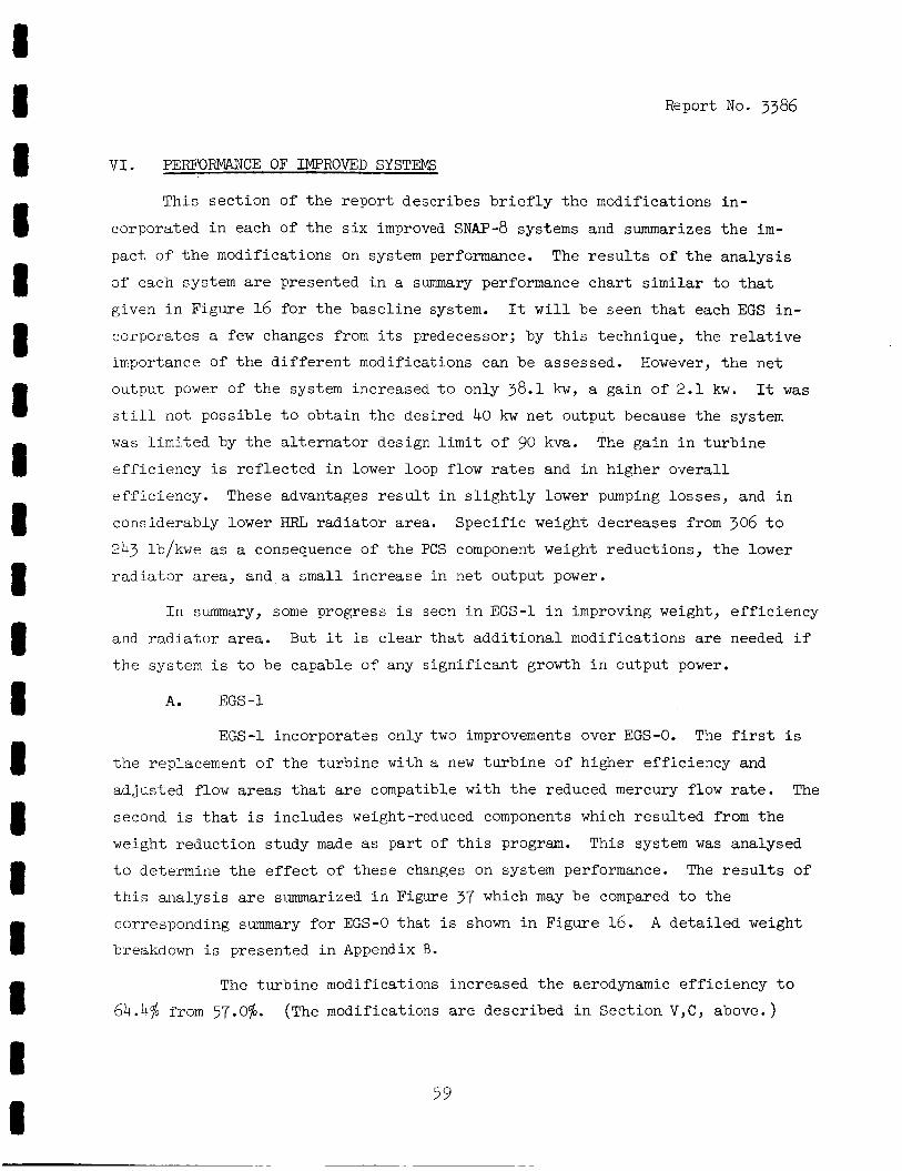
8 8 8 8 8 8 8 8 8 8 I I 8 I 8 8 8 8 I
Report No. 3386
V I . PERFORMANCE OF IMPROVED SYSTEMS
This s ec t ion of t h e r epor t describes b r i e f l y t h e modifications i n -
cmporated i n each of t h e s i x improved SNAP-8 systems and summarizes t h e i m -
pact of t h e modifications on system performance.
of each system are presented i n a summary performance cha r t similar t o t h a t
given i n Figure 16 f o r t h e base l ine system. It w i l l be seen t h a t each EGS i n - corporates a f e w changes from i t s predecessor; by t h i s technique, t h e r e l a t i v e
importance of t h e d i f f e r e n t modifications can be assessed. However, t h e n e t
output power of t h e system increased t o only 38.1 kw, a gain o f 2 .1 kw.
still not possible t o obtain t h e desired 40 kw n e t output because t h e system
w a s l i m i t e d by t h e a l t e r n a t o r design l i m i t o f 90 kva. The gain i n t u r b i n e
e f f i c i e n c y i s r e f l e c t e d i n lower l o o p flow rates and i n higher o v e r a l l
eff ic iency. These advantages r e s u l t i n s l i g h t l y lower pumping losses , and i n
considerably lower HRL r a d i a t o r area.
243 lb/kwe as a consequence of t h e PCS component weight reductions, the lower
r a d i a t a r area, and a small increase i n n e t output power.
The r e s u l t s of t h e a n a l y s i s
It w a s
Spec i f i c weight decreases from 306 t o
I n summary, some progress i s seen i n EGS-1 i n improving weight, e f f i c i e n c y
and r a d i a t o r area. But it i s c l e a r t h a t a d d i t i o n a l modifications are needed i f
t h e system i s t o be capable of any s i g n i f i c a n t growth i n output power.
A. EGS-1
EGS-1 incorporates only two improvements over EGS-0. The f irst is
t h e replacement of t h e tu rb ine with a new t u r b i n e of higher e f f i c i ency and
ad jus t ed flow areas t h a t are compatible with t h e reduced mercury flow rate. The
second i s t h a t i s includes weight-reduced components which r e su l t ed from t h e
weight reduction study made as p a r t o f t h i s program. This system was analysed
t o determine t h e e f f e c t of t hese changes on system performance. The r e s u l t s of
t h i s ana lys i s are summarized i n Figure 37 which may be compared t o t h e
corresponding summary f o r EGS-0 t h a t i s shown i n Figure 16. breakdown i s presented i n Appendix B.
A d e t a i l e d weight
The t u r b i n e modifications increased t h e aerodynamic e f f i c i e n c y t o
64.4% from 57.0%. (The modifications are described i n Sect ion V,C , above. )
59
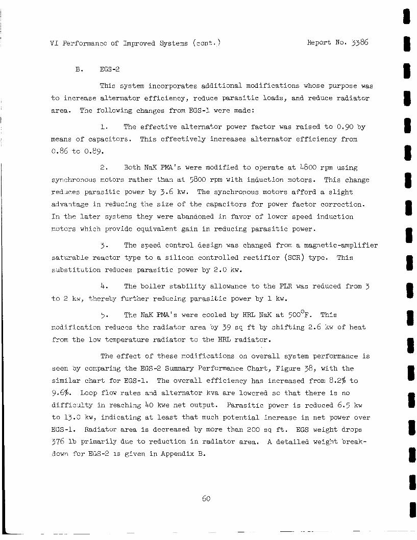
V I Performance of
B. EGS-2
Improved Systems (cont . Report No. 3386
This system incorporates add i t iona l modifications whose purpose was
t o increase a l t e rna to r eff ic iency, reduce p a r a s i t i c loads, and reduce r a d i a t o r
area. The following changes from EGS-1 were made:
1. The e f f ec t ive a l t e r n a t o r power f a c t o r w a s r a i sed t o 0.90 by
means of capacitors. This e f f e c t i v e l y increases a l t e r n a t o r e f f i c i ency from
0.86 t o 0.89.
2. Both NaK PMA's were modified t o operate a t 4800 rpm using
syrchronous motors r a t h e r than a t 5800 rpm with induct ion motors.
reduces pa ras i t i c power by 3.6 kw. advantage i n reducing t h e s i z e of t h e capac i tors f o r power f a c t o r cor rec t ion .
I n t h e la ter systems they were abandoned i n favor of lower speed induct ion
motors which provide equivalent gain i n reducing p a r a s i t i c power.
This change
The synchronous motors a f fo rd a s l i g h t
3. The speed con t ro l design w a s changed from a magnetic-amplifier
s a t w a b l e reactor type t o a s i l i c o n cont ro l led r e c t i f i e r (SCR) type.
s u b s t i t u t i o n reduces p a r a s i t i c power by 2.0 kw.
This
4. The b o i l e r s t a b i l i t y allowance t o t h e PLR w a s reduced from 3 t o 2 kw, thereby f u r t h e r reducing p a r a s i t i c power by 1 kw.
5. The NaK PMA's were cooled by HRL N a K a t 500°F. This
modification reduces t h e r a d i a t o r area by 39 sq f t by s h i f t i n g 2.6 kw of hea t
from t h e low temperature r a d i a t o r t o the HRL r a d i a t o r .
The e f f e c t of t hese modifications on o v e r a l l system performance i s
seen by comparing t h e EGS-2 Summary Performance Chart, Figure 38, w i t h t h e
similar char t f o r EGS-1.
9.6%. difficulty i n reaching 40 kwe ne t output.
t o 13.0 kw, indicat ing a t l e a s t t h a t much p o t e n t i a l increase i n ne t power over
EGS-1. Radiator a r ea i s decreased by more than 200 sq f t . EGS weight drops
376 lb primarily dute t o reduct ion i n r a d i a t o r area.
down f o r EGS-2 i s given i n Appendix B.
The o v e r a l l e f f ic iency has increased from 8.2% t o
Loop flow rates and a l t e r n a t o r kva are lowered so that there is no
P a r a s i t i c power is reduced 6.5 kw
A d e t a i l e d weight break-
60
I I 8 8 I 8 8 I 8 8 1 8 1 8 8 8 8 8 I
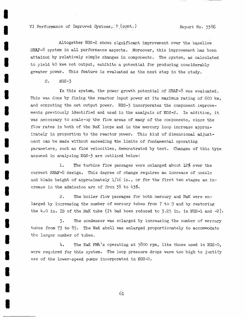
I i 8 8 1 1 8 I I 1 I I 8 8 I 8 8 8 1
V I Performance of Improved Systems, R ( con t . ) Report No. 3386
Altogether EGS-2 shows s i g n i f i c a n t improvement over t h e base l ine
SNAP-8 system i n a l l performance aspec ts .
a t t a i n e d by r e l a t i v e l y simple changes i n components.
t o y i e l d 40 kwe ne t output, exh ib i t s a p o t e n t i a l f o r producing considerably
g r e a t e r power.
Moreover, t h i s improvement has been
The system, as ca lcu la ted
This f ea tu re i s evaluated as t h e next s t e p i n t h e s tudy.
C. EGS-3
I n t h i s system, t h e power growth p o t e n t i a l of SNAP-8 was evaluated.
This w a s d m e by f i x i n g t h e r e a c t o r input power a t i t s maximum r a t i n g of 600 kw,
and computing the ne t output power. EGS-3 incorporates t h e component improve-
ments previously i d e n t i f i e d and used i n t h e ana lys i s of EGS-2. was necessary t o scale-up t h e flow areas of many of t h e components, s ince t h e
flow rates i n both of t he NaK loops and i n t h e mercury loop increase approx-
imately i n proportion t o t h e r eac to r power.
ment can be made without exceeding the l i m i t s of fundamental opera t ing
parameters, such as f l o w v e l o c i t i e s , demonstrated by t e s t . Changes of th i s type
assumed i n analyzing EGS-3 a r e out l ined below:
I n addi t ion , it
This kind of dimensional ad jus t -
1. The tu rb ine flow passages were enlarged about 12% over t h e
This degree of change requi res an increase of nozzle cu r ren t s~W?-8 design.
and b lade he ight of approximately 1/16 in . , or f o r t h e f i rs t two s t ages an i n -
c rease i n the admission a r c of from 38 t o 43%.
2. The b o i l e r flow passages f o r both mercury and NaK were en-
l a rged by increas ing t h e number of mercury tubes from 7 t o 9 and by r e s t o r i n g
t h e 4.0 in . I D of the NaK tube (It had been reduced t o 3.25 in . i n EGS-1 and -2).
3. The condenser w a s enlarged by increas ing t h e number of mercury
tubes from 73 t o 85. t h e l a r g e r number of tubes.
The NaK s h e l l was enlarged propor t iona te ly t o accommodate
4. The NaK PMA's operat ing a t 5800 rpm, l i k e those used i n EGS-0,
were requi red fo r t h i s system. The loop pressure drops were t o o high t o j u s t i f y
use of t h e lower-speed pumps incorporated i n EGS-2.
6 1
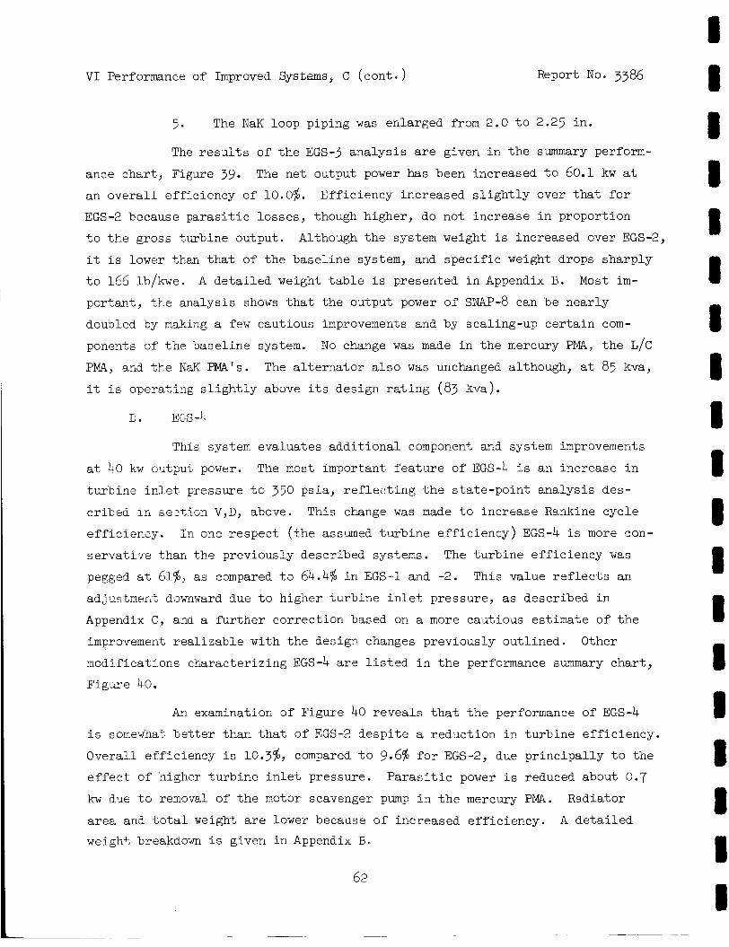
V I Performance of Improved Syskms, C
5. The NaK loop piping
(cont . Report No. 3386
w a s enlarged from 2.0 t o 2 2 5 in .
The results of t h e EGS-3 ana lys i s are given i n t h e summary perform-
The ne t output power has been increased t o 60.1 kw a t ance char t , Figure 39. an ove ra l l e f f ic iency of 10.0%. Eff ic iency increased s l i g h t l y over t h a t f o r
EGS-2 because parasEtic losses , though higher, do not increase i n proportion
t o t h e gross txrbine output. Although t h e system weight i s increased over EGS-2,
it i s lower than t h a t of t h e base l ine system, and s p e c i f i c weight drops sharply
t o 166 lb/kwe.
portant , t h e analysis shows t h a t t h e output power of SNAP-8 can be near ly
doubled by making a f e w cautious improvements and by scaling-up c e r t a i n com-
ponents of t h e base l ine system. No change w a s made i n t h e mercury PMA, t h e L/C
PMA, aqd t h e NaK PMA's. The a l t e r n a t o r a l s o w a s unchanged although, a t 85 kva,
it i s operat ing s l i g h t l y above i t s design r a t i n g (83 kva).
A de t a i l ed weight table i s presented i n Appendix B. Most i m -
This system evaluates add i t iona l component and system improvements
a t 40 kw oiitput power.
t u rb ine i n l e t pressure %o 350 psia , r e f l e c t i n g t h e s ta te -poin t ana lys i s des-
cr ibed i n sez t ion V,D, above. This change w a s made t o increase Rankine cycle
e f f ic iency .
s e rva t ive C,harl the previously described systems. The + , a rbhe e f f i c i ency w a s
pegged a t 61%, a s compared t a 64.4% i n EGS-1 and -2. This value r e f l e c t s ar?
adjustrner4t dawnward due t o higher t u rb ine i n l e t pressure, as described i n
Appendix C, anu a fu t l i e r cor rec t ion based on a more cacitious estimate o f t h e
improvement r ea l i zab le w i t h t h e design changes previously out l ined . Other
modificatioos character iz ing EGS-4 a r e l i s t e d i n t h e performance summary char t ,
F i g c e 40.
The most important f e a t u r e of EGS-4 i s an increase i n
I n one respec t ( t h e assumed tu rb ine e f f i c i ency) EGS-4 i s more con-
An examination 3f Figure 40 revea ls t h a t t h e performance of EGS-4 i s somewhat b e t t e r than t h a t of EGS-2 desp i t e a reduct ion i n tu rb ine e f f ic iency .
Overal l e f f ic iency is 10.3$, compared t o 9.6% f o r EGS-2, due p r inc ipa l ly t o the
e f f e c t of 'higher tu rb ine i n l e t pressure. P a r a s i t i c power i s reduced about 0.7 kw due t o rernoval of the motor scavenger pump i n the mercury PMA.
area and t o t a l weigh% are lower because of increased eff ic iency. weigh+, breakdown i s given i n Appendix B.
Radiator
A de t a i l ed
62
I I I I B 8 8 I I I I B I 8 1 8 I I I
V I Performance of Improved Systems (cont . ) 5
E. EGS-5
This system incorporates a l l of t h e mol i
Report No. 3386
i ca t ions evaluated i n t h e
s tudy which were judged t o be feas ib le .
t he re fo re , i s considered t o approach the u l t ima te p e r f o m n c e p o t e n t i a l of t h e
SNAP-8 system a t 40 kw n e t output.
the following r e spec t s : The tu rb ine aerodynamic e f f i c i ency was increased i n t h e
primary and hea t r e j e c t i o n NaK loops, and t h e N a K PMA's were s ized t o match re-
duced loap pressure drop and flow ra t e s .
The performance computed for EGS-5,
Spec i f i ca l ly , EGS-5 d i f f e r s from EGS-4 i n
The tu rb ine aerodynamic e f f i c i ency was increased t o 62.5%. This
value corresponds t o t h e 64.4% used in EGS-1 and -2 af ter ad jus t ing f o r 350
p s i a t u r b i n e i n l e t p ressure (as described i n Appendix C ) .
b e t t e r cornparison with t h e e a r l i e r systems is obtained, and EGS-5 comes c l o s e r
t o represent ing optimum SNAP-^ performance.
match t h e flow r a t e required f o r t h i s t u r b i n e as determined by t h e system
ana lys i s a t an i n l e t p ressure of 350 ps ia .
I n this manner, a
Turbine flow a r e a was assumed t o
I n order t o reduce the p a r a s i t i c power required by t h e NaK PMA's, t hese components were "rubberized", i .e., sealed t o match t h e pressure drop and
flow r a t e required i n each loop. Hydraulic impedance of t h e primary loop w a s
g r e a t l y reduced i n EGS-4 by using the advanced r eac to r , a modified mercury
b o i l e r , removing t h e PLR from t h i s loop, and increas ing t h e N a K piping s i z e .
Table 13 shows t h e NaK aP allowances made f o r t h e PNL and HRL i n EGS-5 as a
f m c t i o n of loop flow r a t e .
as t h e SNAP-8 development NaK PMA's.
NaK PMA's custom designed for t he respect ive NaK loop AP and flow r a t e .
The NaK PMA's are based on t h e same design concept
Figure 2 1 shows t h e c h a r a c t e r i s i c s of t h e
The EGS-5 system described above w a s then analyzed t o determine
component operat ing condi t ions and system performance.
s u l t i n g summary performance cha r t f o r t h i s system based on a n e t power output
Of 40 b e .
The o v e r a l l e f f ic iency of 10.9% represents a 55% increase over EGS-0.
Figure 41 i s t h e r e -
P a r a s i t i c power i s seen t o be 10.7 kw, 9 kw lower than t h a t of EGS-0.
V I Performance of Improved Systems, X ( c o n t . ) Report No. 3386
The weight f o r t h i s system i s approximately 2300 l b l i g h t e r than
EGS-0, and the r a d i a t o r area i s less than 900 sq f t . The weight saving i s l a r g e l y
due t o t h e change i n FCS s t r u c t u r a l concept, use of weight-reduced components, and
t h e reduced r ad ia to r s i z e .
EGS-5.
Appendix B gives t h e d e t a i l e d weight breakdown f o r
F. EGS-6
This system t akes advantage o f a l l of t h e improvements used i n EGS-5.
The system analysis w a s performed t o establish t h e maximum n e t power output t h a t
could be obtained with a 600-kwt r e a c t a r input , and i n t h a t r e spec t i s comparable
t o EGS-3. The following paragraphs desc r ibe t h e design changes necessary t o
accommodate t h e higher loop flow rates which are t h e consequence of 600 kw input .
1. To reduce t h e p a r a s i t i c power required by t h e N a K PMA's used i n
t h i s EGS, t he hydraulic impedance of both NaK loops w a s reduced as much as poss-
i b l e . I n t h e primary NaK loop, t h e b o i l e r NaK tube s i z e , and t h e N a K pipe s i z e
were increased. I n t h e HRL, t h e r a d i a t o r N a K tubes were increased by 0.030
inches i n diameter, t h e NaK piping w a s increased, and t h e conrienser NaK flow area
w a s increased. These changes were calculated t o give t h e A€' values Lis ted i n
Table 13 a t flow rates compatible with t h e EGS-6 power l e v e l .
N a K PMk's were assmed t o be custom designed t o match t h e loop pressure drop and
flow rates required by the system.
A s i n EGS-5, t h e
2. The mercury b o i l e r used i n EGS-6 was increased i n s i z e t o
meet t h e increased NaK and mercury flows. The number of mercury tubes w a s i n -
creased from 7 t o 9 and t h e NaK tube surrounding t h e s e tubes w a s increased t o
4.55 i n I D .
p s i at. 70,000 lb/hr flow rate.
With t h e s e changes, t h e b o i l e r NaK-side Ai? w a s estimated t o be 1.8
3. The mercury condenser w a s enlarged by inc reas ing t h e number of
mercury tubes from 73 t o 85 and increasing t h e N a K flow area t o reduce t h e
NaK A€' i n t h i s component.
basis of constant mercury flow-rate per tube. The N a K flow area w a s increased
t o y i e l d a pressure drop of 5 p s i a t 50,000 l b / h r flow rate.
The s c a l i n g of t h e number of tubes w a s made on t h e
64
V I Performance of Improved Systems, F (,cont. ) Report No. 3386
The r e s u l t s of t h e EGS-6 performance a n a l y s i s are presented i n
A ne t e l e c t r i c a l output o f 71.1 kwe i s shown f o r t h i s system a t a n Figure 42. o v e r a l l system ef f ic iency of 11.9%. s l i g h t l y exceeds t h e design r a t i n g of t h e present SNAP-8 design.
The a l t e r n a t o r gross output of 86.1 kva
The weight breakdown f o r t h i s system, given i n Appendix B, shows
t h a t t h e weight of t h i s system i s about 1000 lb l i g h t e r than EGS-0.
EGS-6 r a d i a t o r area of 1440 sq f t i s only 7 sq f t g r e a t e r than t h a t of EGS-0,
while t h e ne t power output i s 35.1 kwe grea te r . This demonstrates t he advantages
of t h e modifications made t o t h e system as a r e s u l t of t h i s study.
Also, t h e
Report No. 3386
V I I . INTEGRATION OF THE SNAP-8 EGS WITH A TV SATELLITE AN ILLUSTRATIVE APPLICATION STUDY
A. INTRODUCTION
The performance of improved SNAP-8 power systems having been evalu-
a ted , as described i n the preceding sec t ions of t h i s repor t , it was of i n t e r e s t
t o study a t y p i c a l app l i ca t ion of t h e power system i n an unmanned space mission.
A direct-broadcast TV s a t e l l i t e i n synchronous o r b i t w a s se lec ted as the
mission model, and the EGS-4 power system was chosen as t h e improved power
system model.
study but were taken from ava i l ab le sources as c i t e d herein. Design and per-
formance d a t a for the TV system and o r b i t a l s ta t ion-keeping requirements were
obtained primarily from Space-General Corporation, based on a study of unmanned
appl ica t ions of SNAP-8 conducted under NASA Contract NASw-1069 (Reference 11).
Supplemental information on antenna and t r ansmi t t e r c h a r a c t e r i s t i c s w a s obtained
from TRW Systems and from EIMAC Division of Varian.
organizations is g r a t e f u l l y acknowledged.
Mission and space vehicle d a t a were not generated i n t h e present
The a s s i s t ance of these
1. Scope
The purpose of t h i s study i s t o de f ine and examine t h e major
power system/TV spacecraf t i n t e r f aces and t o pro jec t ove ra l l c h a r a c t e r i s t i c s of
a conceptual vehicle design.
developed t o define t h e vehic le shape, component arrangement and weight
d i s t r i b u t i o n , and t o i d e n t i f y major power system/payload in t e r f aces .
f i gu ra t ion selected i n t h e s tudy i s based on use of a Saturn-class launch
vehicle ( i .e . , one using an S-IVB upper s t age ) .
optimize t h e configuration, but simply t o def ine a f eas ib l e arrangement. Thermal
management of the power and TV systems were analyzed, i n t e r f a c e problems
iden t i f i ed , and c h a r a c t e r i s t i c s of t h e major spacecraf t subsystems are discussed.
I n concluding the study, power system redundancy and increased power output were
examined b r i e f ly .
from 10,000 t o 20,000 hours a l s o w a s evaluated.
For th i s purpose, a conceptual design layout w a s
The con-
The study does not a i m t o
The po ten t i a l fo r increas ing t h e operat ing l i f e of SNAP-8
66
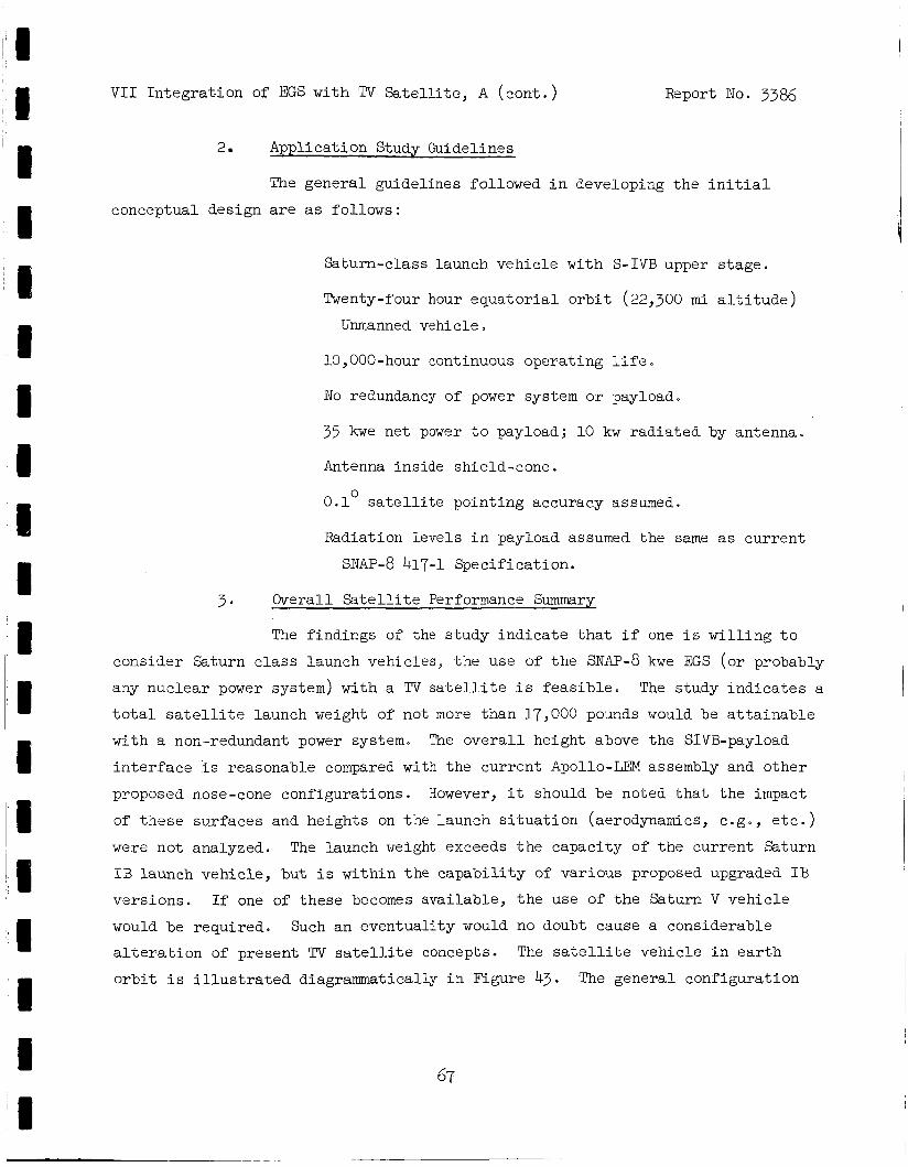
V I 1 In tegra t ion of EGS with TV Satell i te, A ( con t . ) Report No. 3386
2. Application Study Guidelines
The general guidelines followed i n developing t h e i n i t i a l
conceptual design are as follows:
Saturn-class launch vehic le with S-IVB upper s tage .
Twenty-four hour equa to r i a l o r b i t (22,300 m i a l t i t u d e )
Unmanned vehicle
10,000-hour continuous operat ing l i f e .
No redundancy of power system or payload.
35 kwe ne t power t o payload; 10 kw radiated by antenna.
Antenna inside shield-cone.
0.1 s a t e l l i t e po in t ing accuracy assumed. 0
Radiation levels i n payload assumed the same as cur ren t
SNAP-8 417-1 Specif icat ion.
3 . Overall S a t e l l i t e Performance Summary
The f indings of the s tudy ind ica t e t h a t i f one i s w i l l i n g t o
consider Saturn c l a s s launch vehicles, t h e use of t h e SNAP-8 kwe EGS (or probably
any nuclear power system) with a TV s a t e l l i t e i s f eas ib l e . The study ind ica t e s a
t o t a l s a t e l l i t e launch weight of not more than l7,OOO pounds would be a t t a i n a b l e
with a non-redundant power system. The ove ra l l height above the SIVB-payload
i n t e r f a c e i s reasonable compared w i t h the cur ren t Apollo-LEM assembly and o ther
pl-oposed nose-cone configurat ions. However, it should be noted t h a t t h e impact
of these surfaces and heights on the launch s i t u a t i o n (aerodynamics, c .g . , e t c . )
were not analyzed. The launch weight exceeds t h e capaci ty of t he cur ren t Saturn
I B launch vehic le , but i s wi th in the capab i l i t y of var ious proposed upgraded I B
vers ions. If one of these becomes avai lable , t h e use of t h e Saturn V vehic le
would be required.
a l t e r a t i o n of present TV sa t e l l i t e concepts.
o r b i t i s i l l u s t r a t e d diagrammatically i n Figure 43.
Such an eventual i ty would no doubt cause a considerable
The satel l i te vehic le i n e a r t h
The general configurat ion
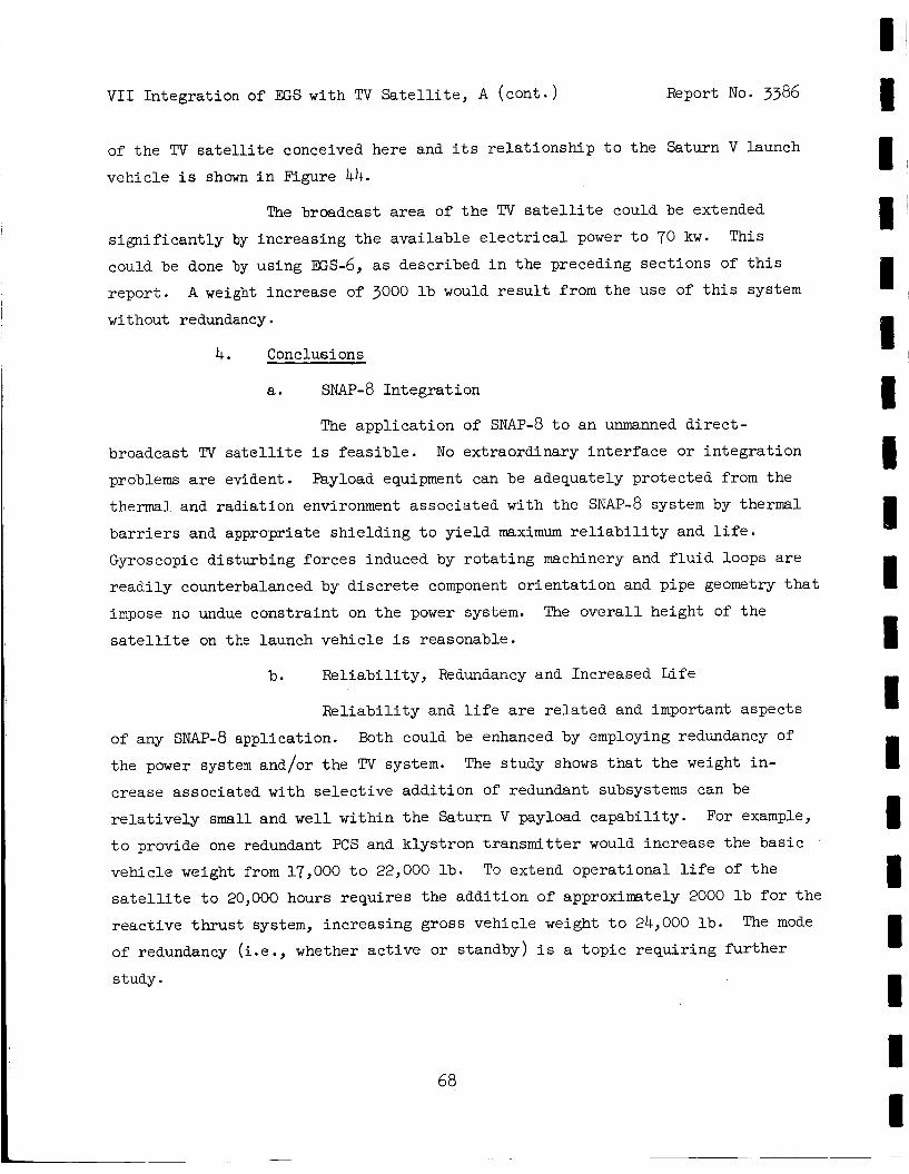
V I 1 In tegra t ion of EGS with TV S a t e l l i t e , A ( con t . ) Report No. 3386
I I
of t h e TV s a t e l l i t e conceived here and i t s r e l a t i o n s h i p t o t h e Saturn V launch
vehic le i s shown i n Figure 44.
The broadcast a r ea of t h e TV s a t e l l i t e could be extended This s i g n i f i c a n t l y by increas ing t h e ava i l ab le e l e c t r i c a l power t o 70 kw.
could be done by using Es-6, a s descr ibed i n t h e preceding sec t ions of t h i s
r e p o r t .
without redundancy.
A weigh t increase of 3000 l b would r e s u l t from t h e use of t h i s system
4. Conclusions
a. SNAP-8 In t eg ra t ion
The app l i ca t ion of SNAP-8 t o an unmanned d i r e c t -
broadcast TV s a t e l l i t e i s f e a s i b l e . No extraordinary i n t e r f a c e o r i n t e g r a t i o n
problems a r e evident.
thermal and rad ia t ion environment assoc ia ted with t h e SNAP-8 system by thermal
b a r r i e r s and appropriate sh i e ld ing t o y i e l d maximum r e l i a b i l i t y and l i f e .
Gyroscopic d is turb ing fo rces induced by r o t a t i n g machinery and f l u i d loops a r e
r e a d i l y counterbalanced by d i s c r e t e component o r i en ta t ion and pipe geometry t h a t
impose no undue cons t r a in t on t h e power system.
s a t e l l i t e on t h e launch vehic le i s reasonable.
Payload equipment can be adequately pro tec ted from t h e
The o v e r a l l height of t h e
b. R e l i a b i l i t y , Redundancy and Increased Life
R e l i a b i l i t y and l i f e a r e r e l a t e d and important aspec ts
of any SNAP-8 appl icat ion.
t he power system and/or t h e TV system.
crease associated with s e l e c t i v e addi t ion of redundant subsystems can be
r e l a t i v e l y small and w e l l wi th in t h e Saturn V payload capab i l i t y .
t o provide one redundant PCS and k lys t ron t r ansmi t t e r would increase t h e bas i c
vehic le weight from 17,000 t o 22,000 l b .
s a t e l l i t e t o 20,000 hours r equ i r e s t he add i t ion of approximately 2000 l b f o r t h e
r eac t ive t h r u s t system, increas ing gross vehic le weight t o 24,000 l b .
of redundancy ( i . e . , whether a c t i v e or standby) i s a t o p i c r equ i r ing f u r t h e r
study.
Both could be enhanced by employing redundancy of
The study shows that t h e weight i n -
For example,
To extend opera t iona l l i f e of t h e
The mode
68
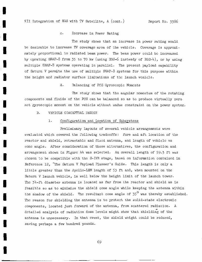
V I 1 In t eg ra t ion of EGS with TV S a t e l l i t e , A ( con t . )
~ ~-
Report No. 3386
c. Increase i n Power Rating
The study shows t h a t an inc rease i n power r a t i n g would
be d e s i r a b l e t o inc rease TV coverage area of t h e veh ic l e .
mately proport ional t o r ad ia t ed beam power.
by up ra t ing SNAP-8 from 35 t o 70 k w (using ~ s - 6 insteady of EGS-4), or by using
mult iple SNAP-8 systems operating i n p a r a l l e l . The present payload c a p a b i l i t y
of Saturn V permits t h e use of multiple SNAP-8 systems f o r t h i s purpose within
t h e height and r a d i a t o r surface l imi t a t ions of t h e launch ven ic l e .
Coverage i s approxi-
The beam power could be increased
d. Balancing of PCS Gyroscopic Moments
The study shows t h a t t h e angular momentum of t h e r o t a t i n g
components and f l u i d s of t h e PCS can be balanced so as t o produce v i r tua l ly zero
n e t u r o s c o p i c moment on t h e vehicle without undue cons t r a in t on t h e power system.
B. VEHICLE CONCEPTUAL DESIGN
1. Configuration and Location of Subsystems
Preliminary layouts of several veh ic l e arrangements were
evaluated which covered t h e following t r a d e o f f s : f o r e and a f t l o c a t i o n of t h e
r e a c t o r ar,d sh ie ld , r e t r a c t a b l e and f ixed antenna, and length of veh ic l e v s
cone angle . A f t e r consideration of these a l t e r n a t i v e s , t h e configurat ion and
arrangement shown i n Figure 44 w a s se lec ted .
chosen t o be compatible with the S-IVB s tage , based on information contained i n
Reference 12, "The Saturn V Payload Planner 's Guide. This length i s only a
l i t t l e g r e a t e r than t h e Apollo-LEM length of 53 f t and, when mounted on t h e
Saturn V launch vehicle , i s we l l be low t h e height l i m i t of t h e launch tower.
The 34-ft diameter antenna i s located as far from t h e r e a c t o r and s h i e l d as i s
f e a s i b l e s o as t o minimize t h e sh i e ld cone angle while keeping t h e antenna wi th in
t h e shadow of t h e s h i e l d .
The reason for sh ie ld ing the antenna i s t o p ro tec t t h e s o l i d - s t a t e e l e c t r o n i c
components, located j u s t forward of the antenna, from s c a t t e r e d r a d i a t i o n . A
An o v e r a l l l eng th of 59.3 f t w a s
The r e s u l t a n t cone angle o f 35' w a s thereby e s t ab l i shed .
detailed a n a l y s i s of r a d i a t i o n dose levels might show t h a t sh i e ld ing of t h e
antenna i s unnecessary. I n t h a t event, t h e shield weight could be reduced,
saving perhaps a few hundred pounds.
69
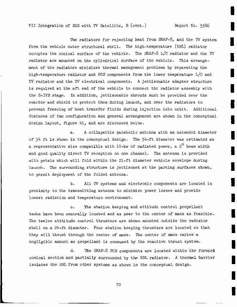
V I 1 In tegra t ion of E S with TV S a t e l l i t e , B ( c o n t . ) Report No. 3386
The r a d i a t o r s f o r r e j e c t i n g heat from SNAP-8, and t h e TV system
form t h e vehicle outer s t r u c t u r a l s h e l l .
occupies the conical surface of t he veh ic l e .
r a d i a t o r are mounted on t h e c y l i n d r i c a l sur face of t h e vehic le .
ment of t h e r ad ia to r s minimizes thermal management problems by separa t ing t h e
high-temperature r a d i a t o r and PCS components from t h e lower temperature L/C and
TV r a d i a t o r and t h e TV e l e c t r i c a l components. A j e t t i s o n a b l e adapter s t r u c t u r e
i s required a t the a f t end of t h e vehic le t o connect t he r a d i a t o r assembly with
t h e S-IVB stage. In addi t ion , j e t t i s o n a b l e shrouds must be provided over t h e
r eac to r and sh ie ld t o pro tec t them during launch, and over t h e r a d i a t o r s t o
prevent f reezing of heat t r a n s f e r f l u i d s during i n j e c t i o n i n t o o r b i t . Addi t ional
f ea tu re s of the configurat ion and general arrangement a r e shown i n t h e conceptual
design layout , Figure 45, and a r e discussed below.
The high-temperature (HRL) r a d i a t o r
The SNAP-8 L/C r a d i a t o r and t h e TV
This arrange-
a. A co l l aps ib l e parabol ic antenna with an extended diameter
of 34 f t i s shown i n t he conceptual design.
a representat ive s i z e compatible with 10-kw of r ad ia t ed power, a 2 beam width
and good qua l i ty d i r e c t TV recept ion on one channel. The antenna i s provided
with p e t a l s which w i l l f o l d within t h e 21-f t diameter vehicle envelope during
launch. The surrounding s t r u c t u r e i s j e t t i s o n e d a t t h e pa r t ing sur faces shown,
t o permit deployment of t h e folded antenna.
The 34-ft diameter was est imated as 0
b. A l l TV systems and e l e c t r o n i c components a r e loca ted i n
proximity t o the t r ansmi t t i ng antenna t o minimize power lo s ses and provide
lowest r ad ia t ion and temperature environment.
c. The s t a t i o n keeping and a t t i t u d e con t ro l propel lan t
tanks have been c e n t r a l l y loca ted and a s near t o t he center of mass as f e a s i b l e .
The twelve a t t t i t u d e con t ro l t h r u s t e r s a r e shown mounted outs ide t h e r a d i a t o r
s h e l l on a 24-ft diameter.
they w i l l t h r u s t through the center of mass. The center of mass v a r i e s a
negl ig ib le amount as propel lan t i s consumed by the r eac t ive t h r u s t system.
Four s t a t i o n keeping t h r u s t e r s a r e loca ted s o t h a t
d. The SNAP-8 PCS components a r e loca ted within t h e forward
A thermal b a r r i e r conica l sec t ion and p a r t i a l l y surrounded by t h e HFG r a d i a t o r .
i s o l a t e s t he HRL from other systems as shown i n t h e conceptual design.
70
1 1
I I I I I I I I 1 1 I 1 1 1 I I
a
V I 1 In tegra t ion of EGS with TV Sa te l l i t e , B (cont . ) Report No. 3386
e. A t o t a l surface a rea of 840 sq f t i n the conical sec t ion
and 1050 sq f t i n t h e c y l i n d r i c a l sect ion i s a v a i l a b l e as r a d i a t o r surface.
This amounts t o 643 sq ft more than the estimated r a d i a t o r a rea requirements.
The vehicle surface i s determined by the cone angle and length which were
s e l e c t e d on t h e bas i s of payload r a d i a t i o n dose c r i t e r i a .
arrangement shown, an a d d i t i o n a l volume of a t l e a s t 5000 cu f t is a v a i l a b l e for
a d d i t i o n a l payload.
With t h e component
f. The system tube-and-fin r ad ia to r s a r e u t i l i z e d as t h e
main vehic le s t ruc ture ; c i rcumferent ia l "Z" r ings and longi tudina l streamers
provide s t i f f e n i n g of t h e r a d i a t o r s against buckling. The s t ruc tu re needed t o
support t h e TV system u t i l i z e s t h e s t r u c t u r a l r i n g at t h e base of t h e c y l i n d r i c a l
r a d i a t o r s h e l l . S t r u c t u r a l support a l so i s provided f o r propel lant tankage i n
t h e c m i c a l sec t ion of t h e vehicle . A 260-in. diameter j e t t i s o n a b l e s t ruc tu re
adapts t h e vehicle r a d i a t o r s t ruc tu re t o the S-IVB s tage . This sec t ion of
s t r u c t u r e surrounds t h e collapsed antenna and i s j e t t i s o n e d upon separat ion
from t h e S-IVB stage.
2. I n t e r f a c e s and In tegra t ion Features
In tegra t ion of SNAP-8 with other systems of an unmanned TV s a t e l l i t e was invest igated t o iden t i fy major considerations necessary i n evolving
t h e conceptual design of a vehicle . It i s not t h e i n t e n t of t h i s study t o r e -
solve a l l in t e r f ace problems, r a t h e r t o i d e n t i e those of major importance, i n -
d i s a t e t h e i r influence on system design and performance, and suggest po ten t i a l
areas for fu r the r study.
a. Thermal Environment
The high-temperature environment associated with SNAP-8
c rea t e s t h e necess i ty t o thermally i s o l a t e e l ec t ron ic equipment, power condition-
ing equipment, low-temperature coolants (such as water and L/C f l u i d ) , as w e l l
as a t t i t u d e cont ro l propel lant , from t h e high temperatures of t he SNAP-8 system.
This i s accomplished by providing a thermal b a r r i e r between t h e HRL r a d i a t o r and
t h e L/C rad ia tor , and i n s t a l l i n g a l l of the major SNAP-8 hardware i n t h e farward
V I 1 In t eg ra t ion of M;S with TV S a t e l l i t e , B ( con t . ) Report No. 3386
conica l sec t ion as shown i n Figure 45. t o t he L/C and TV r a d i a t o r s i s minimized. Further, a l l o ther components except
t h e L/C c i r c u i t , a r e loca ted on t h e payload s i d e of t he thermal b a r r i e r so t h a t
they a r e not adversely a f f e c t e d by high-temperature r a d i a t o r sur faces . Thermal
i n s u l a t i o n i s employed on SNAP-8 components t h a t operate a t temperatures s i g n i f i -
c a n t l y d i f f e r e n t from the HRL r ad ia to r .
Thus, interchange of heat from t h e HRL
To withstand t h e low-temperature environment which w i l l
e x i s t f o r severa l days during o r b i t a l t r a n s f e r maneuvers, t h e veh ic l e i s pro-
vided with a l ight-weight j e t t i s o n a b l e shroud. I n addi t ion , p ropel lan t and
coolant tanks are insu la t ed t o prevent f r eez ing .
Rejection of waste heat from t h e TV power condi t ioning,
rece iv ing and t ransmi t t ing equipment i s accomplished by a cool ing c i r c u i t , i n -
dependent of the SNAP-8 cool ing loops.
coolant, and includes a separa te motor-driven pump and r a d i a t o r .
assumed t h a t of t he 35 kwe supplied, 25 kw w i l l be r e j e c t e d t o space by t h e water
cooling loop.
subsystem i s not t h i s e f f i c i e n t , t h i s cooling load would be higher .
a f f e c t t he s i z e of t he cool ing system and the amount of pumping power required, but
The TV cool ing c i r c u i t uses water as
It has been
This implies a c e r t a i n e f f i c i e n c y of t h e TV subsystem. If t h e TV
This w i l l
I I I I I I I 1 I 1 I w i l l not a f f e c t t h e o v e r a l l i n t e g r a t i o n problem being s tudied . The TV heat r e j e c t i o n
requirements and c h a r a c t e r i s t i c s a r e discussed i n paragraph C,2,b.
b . Radiation Environment
The TV equipment and t h e LCS a r e loca ted i n t h e a f t end
of t h e vehic le where the t o t a l i n t eg ra t ed r a d i a t i o n dose f o r 10,000 hours i s :
Fast neutrons nvt
Gammas 10 r ads
These r ad ia t ion l e v e l s are those e s t ab l i shed f o r t h e
6
SNAP-8 e l e c t r i c a l components as s e t f o r t h i n Reference 13. these l e v e l s f o r o ther equipment i n the veh ic l e w a s not evaluated.
s h i e l d i s s ized t o l i m i t t he r ad ia t ion dose t o the l e v e l s i nd ica t ed a t t h e
separa t ion d is tance defined by t h e veh ic l e configurat ion.
unfolded during operat ion, l i e s wi th in the shadow of t h e s h i e l d i n order t o
prevent r ad ia t ion s c a t t e r which would increase t h e dose received by t h e e l e c t r o n i c
e qui pme n t .
The s u i t a b i l i t y of
The r a d i a t i o n
The TV antenna, when
72
t I I 1 I I I 8
V I 1 In t eg ra t ion of EGS with TV S a t e l l i t e , B ( con t . ) Report No. 3386
If t h e above-noted r a d i a t i o n l e v e l s prove t o be excessive,
they can be reduced by increasing sh ie ld th ickness a t t h e expense of a d d i t i o n a l
weight.
r ad ia t ion , of one order of magnitude would r equ i r e approximately 1000 l b of
a d d i t i o n a l s h i e l d weight. A reduction i n dose of two orders of magnitude
would r equ i r e an a d d i t i o n a l 4000 l b o f s h i e l d weight.
A reduct ion i n dose at t h e payload, i n both neutrons and gamma
3. Weight Estimate
The weight estimate f o r the power system w a s taken from t h e
weights developed f o r EGS-4.
sh i e ld cone angle and f o r reduced r ad ia to r a rea . The la t te r r e s u l t s from
opera t ion o f t h e r a d i a t o r s i n syrichronous o r b i t wi th a t t endan t reduct ion i n t h e
inc iden t thermal r ad ia t ion from t h e ear th . The weight es t imates f o r t h e TV
system were obtained from t h e sources previously c i t ed , i n p a r t i c u l a r , Reference
11.
descr ibed i n paragraph C 9 3 below. The gross launch weight of t he vehic le w a s
es t imated a t 17,000 l b for a nonredundant 35-kw power system and a 10,000-hour
a t t i t u d e con t ro l system. Af t e r j e t t i son ing s t r u c t u r e and shrouds, t h e f l i g h t
weight of t h e vehic le i s a l i t t l e l e s s than 15,000 l b .
down f o r t h e vehic le i s presented i n Table 18.
Those weights were ad jus ted for t h e increased
The weights for t h e a t t i t u d e control system were generated i n t h e s tudy as
A summary weight break-
O f launch vehicles now being developed, only Saturn V has the
c a p a b i l i t y of placing t h i s vehic le i n synchronous o r b i t . The Saturn V payload
c a p a b i l i t y i n synchronous o r b i t i s estimated t o be 62,000 l b .
a v a i l a b l e booster , Saturn I B , has a c a p a b i l i t y of only about 8000 l b .
The next l a r g e s t
If other launch vehicles, such as t h e Sa turn I B , were up-
graded t o increase payload capabi l i ty , s a t e l l i t e launch weight may become a
s i g n i f i c a n t cons t r a in t .
f o r reducing launch weight by de ta i led weight opt imizat ion s tud ie s .
a few examples:
If t h i s were t h e case, t h e r e are seve ra l p o s s i b i l i t i e s
To mention
a. A low-freezing-point hea t r e j e c t i o n f l u i d , such as
sodium-potassium-cesium a l l o y might permit e l imina t ion of t h e shroud over t h e
r a d i a t o r s .
73
VI1 Integrat ion of E S with TV S a t e l l i t e z B (cont . Report No. 3386
b. Shield weight might be reduced by reducing t h e shadow
cone angle i f analysis showed r a d i a t i o n s c a t t e r fran the antenna t o be n e g l i -
g i b l e .
c. Radiator weight could be reduced by increasing r a d i a t o r
area as indicated i n Sect ion III,C,3 of t h i s repor t .
d. The reac t ion cont ro l system weight might be optimized
by s e l e c t i n g higher performance propel lan ts or by allowing t h e vehic le t o d r i f t
out-of-plane and compensating f o r t h e d r i f t by a t t i t u d e cont ro l cor rec t ions .
(At t i tude control adjustments genera l ly requi re less propel lant than s t a t i o n -
keeping maneuvers. )
Optimization s tud ie s l i k e t h e s e are beyond t h e scope of t h e
present study, b u t t he re i s no question t h a t s i g n i f i c a n t weight savings could
be r e a l i z e d i f launch weight were t h e major c r i t e r i o n f o r vehic le design for a
p a r t i c u l a r mission.
C . SUBSYSTEM CHARACTERISTICS
1. SNAP-^ EGS
The power system performance c h a r a c t e r i s t i c s used i n t h e
vehic le in tegra t ion study were taken from t h e d a t a f o r EGS-4 which a r e presented
i n Sect ion VI,D of t h i s repor t .
requirements of t h e SNAP-8 development program as s e t f o r t h i n Reference 13. O f
primary concern i n t h e appl ica t ion study a r e t h e power r a t ings of 35 kwe output;
120/208 vol t s , ac, a t 400 cps; and 0.85 power f ac to r a t t h e payload. Radiator
a reas have been adjusted downward t o account f o r t h e very low inc ident thermal
r a d i a t i o n from ea r th i n a 22,300 m i l e o r b i t .
Power output r a t ings of EGS-4 conform t o t h e
Weight of t h e power system w a s
rev ised t o account
SNAP-8 performance
are given i n Table
f o r a l a r g e r sh ie ld , and lower r a d i a t o r areas. A summary of
and s p e c i f i c a t i o n d a t a appl icable t o t h e TV vehic le study
19.
'14
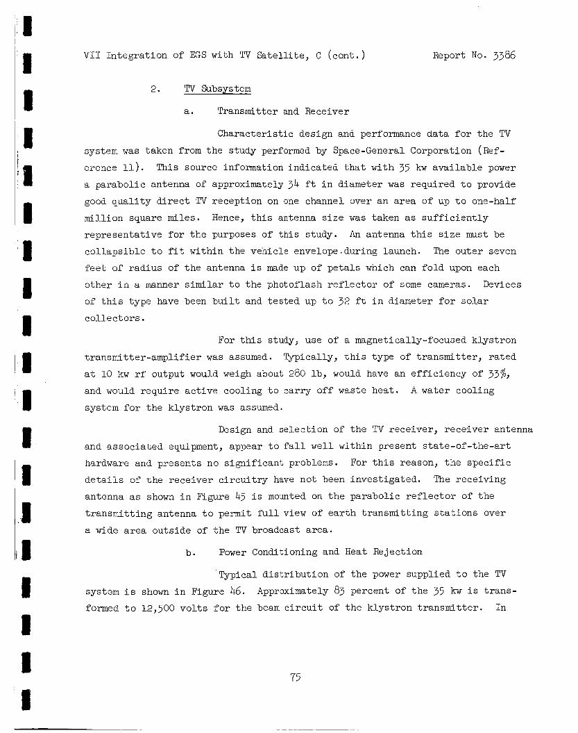
VI1 In t eg ra t ion of EGS with TV S a t e l l i t e , C (cant.) Report No. 3386
2. TV Subsystem
a. Transmitter and Receiver
Charac te r i s t ic design and performance da ta f o r t he TV
system was taken from t h e study performed by Space-General Corporation (Ref-
erence 11). This source information ind ica ted t h a t with 35 kw ava i l ab le power
a parabol ic antenna of approximately 34 f t i n diameter w a s required t o provide
good q u a l i t y d i r e c t TV recept ion on one channel over an a rea of up t o one-half
mi l l ion square miles. Hence, t h i s antenna s i z e w a s taken as s u f f i c i e n t l y
representa t ive f o r t h e purposes of t h i s study. An antenna t h i s s i z e must be
co l l aps ib l e t o f i t within the vehicle envelope-during launch.
feet of rad ius of t h e antenna i s made up of p e t a l s which can f o l d upon each
other i n a manner similar t o the photoflash r e f l e c t o r of some cameras. Devices
of t h i s type have been b u i l t and t e s t ed up t o 32 f t i n diameter f o r s o l a r
co l l ec to r s .
The outer seven
For t h i s study, use of a magnetically-focused k lys t ron
t ransmi t te r -ampl i f ie r w a s assumed. Typically, t h i s type of t r ansmi t t e r , r a t ed
a t 10 kw rf output would weigh about 280 lb , would have an e f f i c i ency of 3376, and would requi re a c t i v e cooling t o car ry o f f waste hea t .
system f o r t h e k lys t ron w a s assumed.
A water cooling
Design and se lec t ion of t h e TV receiver , rece iver antenna
and assoc ia ted equipment, appear t o f a l l w e l l wi th in present s ta te -of - the-ar t
hardware and presents no s ign i f i can t problems. For t h i s reason, t h e s p e c i f i c
d e t a i l s of t h e rece iver c i r c u i t r y have not been inves t iga ted .
antenna as shown i n Figure 45 i s mounted on t h e parabol ic r e f l e c t o r of t h e
t r ansmi t t i ng antenna t o permit full view of e a r t h t ransmi t t ing s t a t i o n s over
a wide area outs ide of t h e TV broadcast area.
The receiving
b. Power Conditioning and Heat Rejection
Typical d i s t r i b u t i o n of t h e power suppl ied t o the TV
system i s shown i n Figure 46. formed t o 12,500 v o l t s f o r t h e beam c i r c u i t of t h e k lys t ron t r ansmi t t e r .
Approximately 83 percent of t h e 35 kw i s t r ans -
In
75
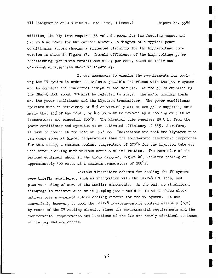
V I 1 In tegra t ion of E S with TV S a t e l l i t e , C ( con t . ) Report No. 3386
addi t ion , t h e klystron r equ i r e s 33 v o l t dc power f o r the focusing magnet and
5.5 v o l t a c power f o r t he cathode hea ter .
condi t ioning system showing a suggested c i r c u i t r y f o r t h e high-voltage con-
vers ion i s shown i n Figure 47. condi t ioning system w a s e s t ab l i shed a t 87 per cent , based on ind iv idua l
component e f f i c i e n c i e s shown i n Figure 47.
A diagram of a t y p i c a l power
Overall e f f i c i e n c y of t h e high-voltage power
It w a s necessary t o examine t h e requirements f o r cool-
ing the TV system i n order t o evaluate poss ib le i n t e r f a c e s w i t h t he power system
and t o complete t h e conceptual design of t h e vehic le . O f t he 35 kw suppl ied by
the SNAP-8 M;S, about TO$ must be r e j e c t e d t o space.
a r e the power conditioner and t h e k lys t ron t r ansmi t t e r .
operates wi th an e f f i c i ency of 87% on v i r t u a l l y a l l of t he 35 kw supplied; t h i s
means t h a t l3$ o f the power, or 4.5 kw must be removed by a cool ing c i r c u i t a t
temperatures not exceeding 200 F. The k lys t ron tube rece ives 29.8 k w from the
power conditioner and operates a t an est imated e f f i c i ency of 33%; the re fo re ,
it must be cooled a t the rate of 19.8 kw.
can s tand somewhat higher temperatures than t h e s o l i d - s t a t e e l e c t r o n i c components.
For t h i s study, a maximum coolant temperature of 270 F f o r t h e k lys t ron tube was
used a f t e r checking with var ious sources of information.
payload equipment shown i n the block diagram, Figure 46, r equ i r e s cooling of
approximately 400 watts a t a maximum temperature of 200 F.
The major cooling loads
The power condi t ioner
0
Indica t ions a r e that t h e k lys t ron tube
0
The remainder of t h e
0
Various a l t e r n a t i v e schemes f o r cooling t h e TV system
were b r i e f l y considered, such as in t eg ra t ion w i t h t h e SNAP-8 L/C loop, and
passive cooling of some of t h e smaller components. In t h e end, no s i g n i f i c a n t
advantage i n r ad ia to r a rea or i n pumping power could be found i n these a l t e r -
na t ives over a separate a c t i v e cooling c i r c u i t f o r t h e TV system.
convenient, however, t o cool the SNAP-8 low-temperature c o n t r o l assembly (LCA)
by means of the TV cooling c i r c u i t , s ince t h e environmental requirements and the
environmental requirements and loca t ions of t h e LCA a r e near ly i d e n t i c a l t o those
It w a s
of the payload components.
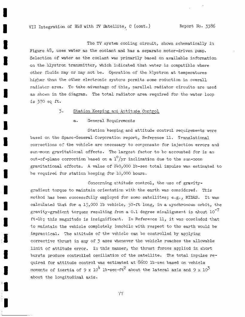
VI1 In t eg ra t ion of EGS with TV Satel l i te , C (cont . ) Report No. 3386
The TV system cooling c i r c u i t , shown schematically i n
Figure 48, uses water as the coolant and has a sepa ra t e motor-driven pump.
Se lec t ion of water as t h e coolant was pr imari ly based on a v a i l a b l e information
on the k lys t ron t r ansmi t t e r , which indicated t h a t water i s compatible where
o the r f l u i d s may or may not be. Operation of t h e k lys t ron a t temperatures
higher than t h e other e l e c t r o n i c systems permits some reduct ion i n o v e r a l l
r a d i a t o r area. To take advantage of th is , parallel r a d i a t o r c i r c u i t s are used
as shown i n the diagram. The t o t a l r a d i a t o r a r e a required f o r the water loop
i s 370 sq f t .
3 * S t a t i o n Keeping and A t t i t u d e Control
a. General Requirements
S t a t i o n keeping and a t t i t u d e c o n t r o l requirements were
based on t h e Space-General Corporation r epor t , Reference 11. Trans l a t iona l
co r rec t ions o f t h e vehicle are necessary t o compensate f o r i n j e c t i o n e r r o r s and
sun-moon g r a v i t a t i o n a l e f f e c t s . The l a r g e s t f a c t o r t o be accounted f o r i s an
out-of-plane co r rec t ion based on a 1°/yr i n c l i n a t i o n due t o the sun-moon
g r a v i t a t i o n a l e f f e c t s .
be required f o r s t a t i o n keeping f o r 10,000 hours.
A value o f 240,000 lb-sec t o t a l impulse w a s estimated t o
Concerning a t t i t u d e control , t he use of g rav i ty -
gradient torque t o maintain o r i en ta t ion with t h e earth was considered. This
method has been success fu l ly employed f o r some satel l i tes ; e.g. , MIDAS. It w a s
ca l cu la t ed t h a t f o r a 15,000 l b vehicle, 50-ft long, i n a synchronous o r b i t , the
gravi ty-gradient torques r e s u l t i n g from a 0 .1 degree misalignment i s about
f t - l b ; t h i s magnitude i s i n s i g n i f i c a n t , I n Reference 11, it w a s concluded t h a t
t o maintain t h e veh ic l e completely immobile with r e spec t t o the earth would be
imprac t i ca l . The a t t i t u d e of t h e vehicle can be con t ro l l ed by applying
c o r r e c t i v e t h r u s t i n any of 3 axes whenever t h e veh ic l e reaches the allowable
l i m i t of a t t i t u d e e r r o r . I n this manner, the t h r u s t fo rces appl ied i n sho r t
b u r s t s produce control led o s c i l l a t i o n o f t h e sa te l l i t e . The t o t a l impulse re-
quired f o r a t t i t u d e c o n t r o l w a s estimated a t 8600 lb-sec based on vehicle moments of i n e r t i a of 9 x l o 4 lb-see- f t2 about the la teral a x i s and 9 x 10 3
about t h e long i tud ina l a x i s .
77
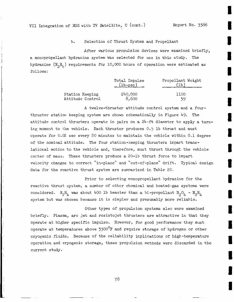
VI1 In tegra t ion of EGS with TV S a t e l l i t e , C ( con t . ) Report No. 3386 1
a monopropellant
hydrazine ( N2H4 ) follows :
b. Se lec t ion of Thrust System and Propel lan t
A f t e r var ious propulsion devices were examined b r i e f l y ,
I hydrazine system w a s s e l ec t ed f o r use i n th i s s tudy. The
requirements f o r 10,000 hours of operat ion were est imated as
T o t a l Impulse Propel lan t Weight ( l b - s e c ) ( l b )
S t a t i o n Keeping 240,000 At t i t ude Control 8,600
1100 39
A twelve- thrus te r a t t i t u d e con t ro l system and a four -
t h r u s t e r s t a t i o n keeping system a r e shown schematical ly i n Figure 49. a t t i t u d e control t h r u s t e r s opera te i n p a i r s on a 24- f t diameter t o apply a t u r n -
ing moment t o the vehic le .
opera te f o r 0.02 sec every 20 minutes t o maintain the vehic le wi th in 0.1 degree
o f t h e nominal a t t i t u d e . The four s ta t ion-keeping t h r u s t e r s impart t r a n s -
l a t i o n a l motion t o t h e veh ic l e and, t he re fo re , must t h r u s t through t h e veh ic l e
cen te r of mass. These t h r u s t e r s produce a 20-lb t h r u s t force t o impart
ve loc i ty changes t o co r rec t "in-plane" and "out-of -plane" d r i f t .
da t a fo r t h e reac t ive t h r u s t system are summarized i n Table 20.
The
Each t h r u s t e r produces 0.5 l b t h r u s t and must
Typical design
P r i o r t o s e l e c t i n g monopropellant hydrazine f o r t h e
r e a c t i v e t h r u s t system, a number of o the r chemical and heated-gas systems were
considered. N H
system but w a s chosen because it i s simpler and presumably more r e l i a b l e .
was about 400 l b heavier than a b i -propel lan t N204 - N2H4 2 4
Other types of propuls ion systems a l s o were examined
b r i e f l y . Plasma, a r c j e t and r e s i s t o j e t t h r u s t e r s a r e a t t r a c t i v e i n t h a t they
opera te a t higher s p e c i f i c impulse. However, f o r good performance they must
opera te a t temperatures above 3500°F and r e q u i r e s to rage of hydrogen or other
cryogenic f lu ids . Because of t he r e l i a b i l i t y impl ica t ions of high-temperature
operat ion and cryogenic s torage, t hese propuls ion methods were discarded i n the
cur ren t study.
I 1 I
V I 1 In t eg ra t ion of EGS with TV S a t e l l i t e , c (cant.) Report No. 3386
C. I n t e r n a l and Externa l Disturbances
I n t e r n a l and e x t e r n a l dis turbances may cause s a t e l l i t e
d r i f t or r o t a t i o n . One possible source of d i s turbance i s t h e angular momentum
of t h e SNAP-8 r o t a t i n g machinery and f l u i d s .
t ending t o produce a d i s tu rb ing torque on the veh ic l e i s t h e TAA which has an
angular momentum of 89 f t - lb-sec.
d i s t u r b i n g torque of 0.0065 f't-lb on t h e veh ic l e as a r e s u l t o f precession a t
t h e r a t e of 1 revolu t ion every 24 hours.
r o t a t e 0.1 degree i n approximately 4.5 minutes.
p rope l lan t N2H4, operat ing continuously, would be required t o compensate f o r
t h i s torque . The p o s s i b i l i t y of countering t h i s e f f e c t was examined.
The l a r g e s t s i n g l e component
T h i s angular momentum w i l l produce a
This moment w i l l cause t h e veh ic l e t o
Approximately 100 l b o f mono-
The angular momentum of a l l other r o t a t i n g components
and t h e b o i l e r were estimated as follows:
PN PMA 2.9
HR PMA 2.9
MPMA 2.1
L/C PMA 0.2
Boi le r 7.7 Tota l 15.8 f t - l b - sec
I n t h e conceptual design layout , Figure 45, these
components and t h e TAA were mounted with t h e i r a x i s of r o t a t i o n p a r a l l e l t o t h e
l o n g i t u d i n a l a x i s of t h e vehic le i n such a way as t o counteract t h e angular
moment of t h e TAA. A ne t unbalanced angular momentum of 73 f t - lb - sec r e s u l t e d .
It was determined t h a t t h i s unbalanced fo rce could be n u l l i f i e d by rou t ing t h e
primary NaK piping through two 9-ft diameter t u rns .
o t h e r f l u i d loops i s e a s i l y balanced without undue cons t r a in t on pipe rout ing .
The angular momentum of
The unbalanced torques produced during s t a r t u p of SNAP-8
a l s o were examined. A s the worst case, t h e dis turbances caused by acce le ra t ion
o f the TAA during s t a r t i n g with no counter-balancing forces w a s determined.
79
80
-
V I 1 Integrat ion of EGS with TV S a t e l l i t e , C ( con t . ) Report No. 3386
This dis turbing torque w a s found t o cause an angular v e l o c i t y of the vehic le
of 0 .1 rpm which requi res a negl ig ib le amount of propel lant f o r cor rec t ion of
vehicle posi t ion.
Micrometeoroid impingement disturbances on the vehic le
a l s o were e s t i m t e d .
designed t o protect against , a momentum of 5.8 x lb-sec was ca lcu la ted .
This requi res an equal t h r u s t impulse t o counteract, and i s seen t o be negl i -
g ib l e . A r e l a t i v e l y la rge meteoroid of t e n grams mass would have a momentum
of 45 lb-sec. This would require about 0.2 ob of propel lant t o counteract.
Considering the l a r g e s t p a r t i c l e which r a d i a t o r armor i s
D. POWER INCREASE AND REDUNDANCY
Since the Saturn V booster has t h e c a p a b i l i t y of l i f t i n g much more
than 17,000 lb , it i s of i n t e r e s t t o examine t h e advantage t h a t increased
launch weight might o f f e r i n vehicle performance, l i f e , and r e l i a b i l i t y .
Vehicle performnce ( i . e . , broadcast a rea and q u a l i t y ) could be enhanced by
increas ing avai lable power. SNAP-8 power output can be e s s e n t i a l l y doubled
by using EGS-6 ins tead of EGS-4, with a r e l a t i v e l y small weight increase.
Redundancy can be used t o increase r e l i a b i l i t y , or l i f e (or both, i f more
than one redundant system i s employed).
of the SNAP-8 FGS i s discussed i n paragraph E, below. Table 21 summarizes
the e f f e c t of power increase and redundancy on vehic le s i ze , weight, and
performance. In general , t he t ab le i n d i c a t e s t h a t a la rge p o t e n t i a l f o r
growth e x i s t s within t h e capabi l i ty of Saturn V.
weight and configuration t rade-of fs , o v e r a l l r e l i a b i l i t y , and operating l i f e
warrant much more study i n the context of a direct-broadcast TV s a t e l l i t e
mission.
Another approach t o increasing l i f e
Redundancy concepts, vehic le
E. POTENTIAL OF SNAP-8 EGS FOR 20,000-HOUR OPERATING LIFE
The importance of increased operat ing l i f e f o r space power systems
has been s t ressed i n numerous mission s tud ie s concerning SNAP-8 and other power
systems for both manned and unmanned missions. The present SNAP-8 design l i f e
VI1 In t eg ra t ion of M;S with TV S a t e l l i t e , E ( con t . ) Report No. 3386
i s a minimum of 10,000 hours.
f o r increased l i f e , from 10,000 t o 20,000 hours, w a s e s t ab l i shed as one of
t he objec t ives of t h e present study.
s e l ec t ed on t h e basis t h a t i e w a s consis tent with t r ends i n planning of long
dura t ion missions. The present study at tempts t o i d e n t i f y t h e most probable
l i f e - l i m i t i n g f a c t o r s of t h e power sys tem.
q u a l i t a t i v e because f a i l u r e modes for most of t h e components have not ye t been
i d e n t i f i e d by continuing development t e s t s .
An assessment of t h e p o t e n t i a l f o r SNAP-8
This increase by a f a c t o r of two was
The assessment i s necessar i ly
1. Assessment of Possible Fa i lure Modes
To a s ses s the po ten t i a l f o r extended l i f e of SNAP-8, poss ib le
wearout f a i l u r e modes of t h e components of t he PCS were examined t o i d e n t i f y
those c h a r a c t e r i s t i c s which a r e l i f e - l i m i t i n g . I n the following paragraphs,
t h e components judged t o be subjec t t o wearout f a i l u r e i n l e s s than 20,000 hours
a r e discussed.
a. Boiler
Based on present developmental experience with mercury
b o i l e r s , t h e most l i k e l y f a i l u r e mode of t h i s component i s by corrosion of t h e
mercury containment tubes.
perienced t o da te .
A program i s now i n progress t o develop b o i l e r f a b r i c a t i o n techniques using
tantalum as t h e mercury containment mater ia l . It has been known t h a t tantalum
(and o the r r e f r ac to ry metals) has f a r lower s o l u b i l i t i e s i n mercury than gCr- 1Mo. it i s expected t h a t r e f r ac to ry , or re f rac tory- l ined b o i l e r tubes w i l l be more
than s u f f i c i e n t t o meet t h e 10,000-hour l i f e requirement.
l i f e t o 20,000 hours should involve a r e l a t i v e l y small, i f any, add i t iona l i m -
pact on t h e SNAP-8 system.
than ordinary s t e e l s , an increase i n metal thickness t o extend l i f e from 10,000
Mercury corrosion of b o i l e r tubes has been ex-
The reference b o i l e r tube mater ia l has been gCr-lMo s t e e l .
When the new b o i l e r design and f a b r i c a t i o n procedures have been determined,
Therefore, t o extend
Since the r e f r a c t o r y metals have much higher dens i ty
81
V I 1 Integrat ion of M;S with TV S a t e l l i t e , E ( con t . ) Report No. 3386
t o 20,000 hours would probably involve some weight penal ty .
increase of 100 l b w a s estimated.
A maximum weight
b. Condenser
The SNAP-8 condenser i s subjec t t o the same s o r t of
a t t a c k by mercury but t o a l e s s e r degree than the b o i l e r .
denser corrosion has not been found t o be a problem.
ing show t h a t the condenser mean-time-to-failure i s l e s s than 20,000 hours,
t he probable solut ion to t he problem would be t o change t h e mater ia l t o a
r e f r a c t o r y metal.
estimated.
To date , con-
Should subsequent t e s t -
To accomplish t h i s a maximum weight increase of 30 l b w a s
c . Rolling Contact Bearings
Precis ion b a l l bearings l u b r i c a t e d by polyphenyl e the r
(MIX-hqE) a r e used i n the TAA and i n the MPMA. Analysis has indicated t h a t
t he fa t igue l i f e of these bearings i s wel l i n excess of 20,000 hours. Wear-
out f a i l u r e s of t he bearings i n l e s s than 20,000 hours may be experienced.
If, and when, such f a i l u r e s a r e iden t i f i ed , t h e probable so lu t ions t o the
problem a r e :
(1) Reduce bearing load. To reduce bearing load,
i t i s necessary t o inves t some weight i n redesign of components t o accommodate
l a r g e r bearing s izes .
so lu t ion .
A weight penalty of up t o 100 l b i s estimated f o r this
( 2 ) Select a b e t t e r l ub r i can t . To improve the
lubr icant , an experimental program i s necessary t o assure t h a t a p o t e n t i a l l y
b e t t e r lubricant , such as high-grade mineral o i l , has t h e c a p a b i l i t y t o with-
s tand the rad ia t ion and temperature environment of SNAP-8.
mineral o i l w a s found unsa t i s fac tory due t o t h e r a d i a t i o n environment, it might involve a weight penal ty t o provide a d d i t i o n a l sh ie ld ing f o r the lub r i can t . At t h i s point even a rough est imate of pena l t ies which must be imposed on the FCS
i s not possible .
If the use of
82
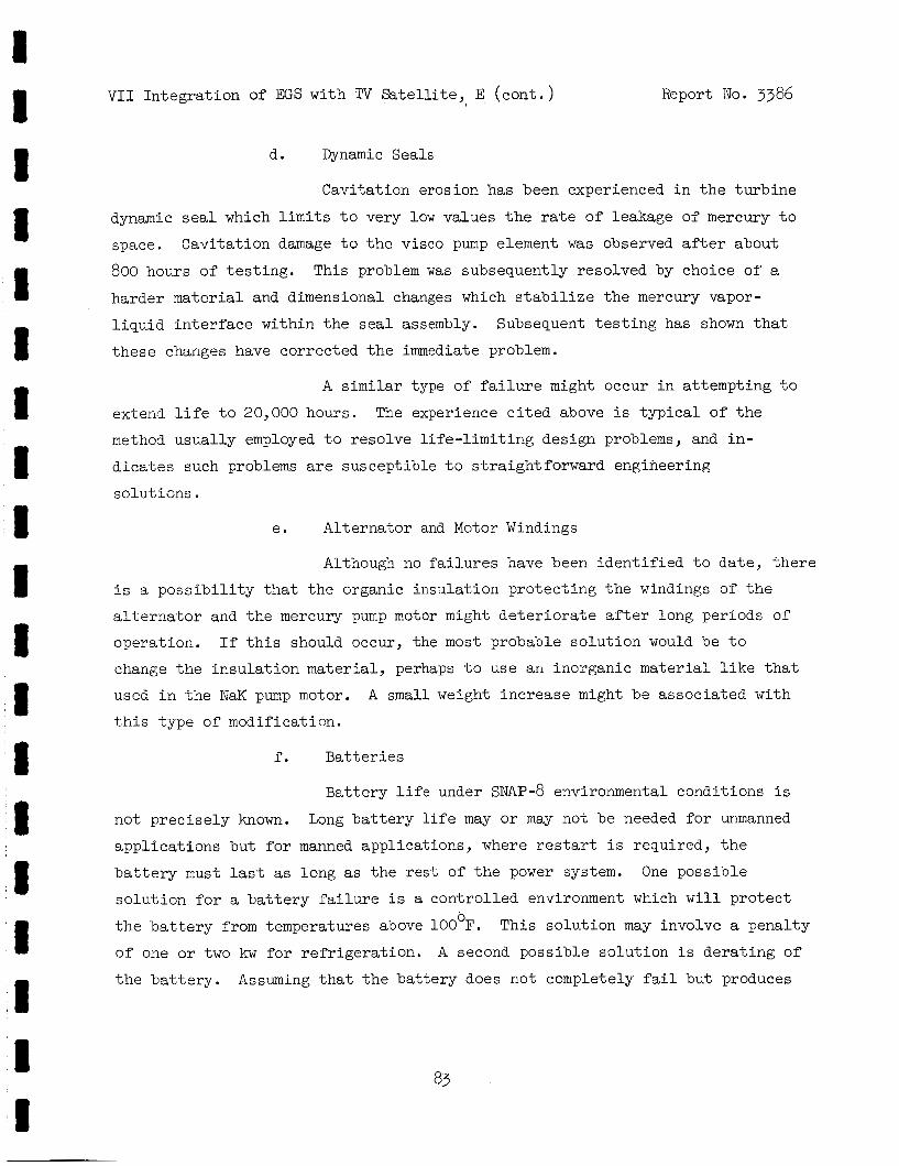
VI1 In t eg ra t ion of EGS with TV S a t e l l i t e , E ( c o n t . ) Report No . 3386
d. Dynamic Seals
Cavi ta t ion erosion has been experienced i n t h e t u r b i n e
dynamic seal which l i m i t s t o very low values the r a t e of leakage of mercury t o
space.
800 hours of t e s t i n g .
harder ma te r i a l and dimensional changes which s t a b i l i z e t h e mercury vapor-
l i q u i d i n t e r f a c e wi th in t h e s e a l assembly.
t h e s e changes have corrected t h e immediate problem.
Cavi ta t ion damage t o t h e visco pump element w a s observed after about
This problem was subsequently resolved by choice of a
Subsequent t e s t i n g has shown t h a t
A similar type of f a i l u r e might occur i n a t tempting t o
extend l i f e t o 20,000 hours.
method usua l ly employed t o reso lve l i f e - l i m i t i n g design problems, and i n -
d i c a t e s such problems are suscept ib le t o s t ra ight forward engineering
so lu t ions .
The experience c i t e d above i s t y p i c a l of t h e
e. Al te rna tor and Motor Windings
Although no f a i l u r e s have been i d e n t i f i e d t o da t e , t h e r e
i s a p o s s i b i l i t y t h a t t h e organic insu la t ion p ro tec t ing t h e windings of t h e
a l t e r n a t o r and t h e mercury pump motor might d e t e r i o r a t e after long per iods of
operat ion. If t h i s should occur, the most probable s o l u t i o n would be t o
change t h e i n s u l a t i o n mater ia l , perhaps t o u s e an inorganic ma te r i a l l i k e t h a t
used i n t h e NaK pump motor.
tihis type of modif icat ion.
A small weight increase might be assoc ia ted with
f . B a t t e r i e s
Bat te ry l i f e under SNAP-8 environmental condi t ions i s
not p rec i se ly known. Long b a t t e r y l i f e may or may not be needed f o r unmanned
app l i ca t ions but f o r manned appl ica t ions , where restart i s required, t h e
b a t t e r y must last as long as t h e r e s t of t h e power system. One poss ib le
s o l u t i o n f o r a b a t t e r y f a i l u r e is a con t ro l l ed environment which w i l l p ro t ec t
t h e b a t t e r y from temperatures above 100oF.
of one or two kw for r e f r i g e r a t i o n .
t h e b a t t e r y .
This so lu t ion may involve a penal ty
A second poss ib le so lu t ion i s d e r a t i n g of
Assuming t h a t t h e ba t t e ry does not completely f a i l bu t produces
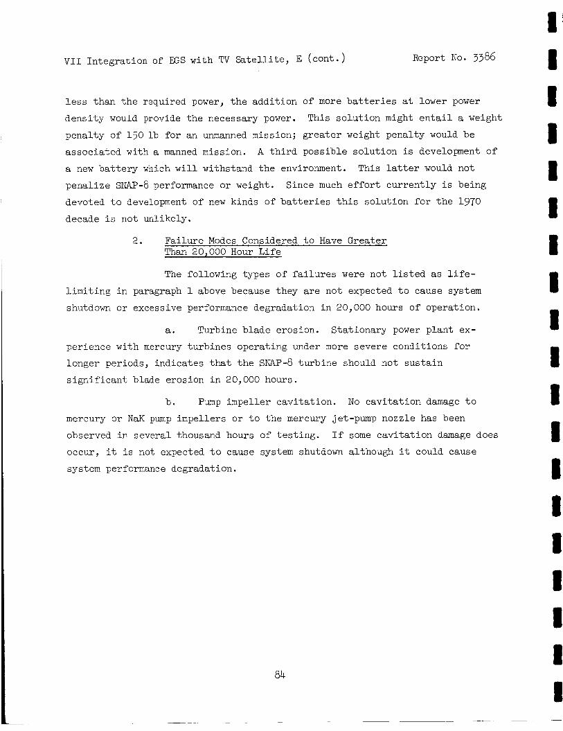
V I 1 In tegra t ion of EGS with TV S a t e l l i t e , E (cont . ) Report No. 3386
less than t h e required power, t h e addi t ion of more b a t t e r i e s a t lower power
dens i ty would provide t h e necessary power. This so lu t ion might e n t a i l a weight
penal ty of 150 l b f o r an unmanned mission; g rea t e r weight penal ty would be
assoc ia ted with a manned mission. A t h i r d possible so lu t ion i s development of
a new b a t t e r y which w i l l withstand the environment.
penal ize SNAP-8 performance or weight.
devoted t o development of new kinds of b a t t e r i e s t h i s so lu t ion f o r t h e 1970 decade i s not unlikely.
This l a t te r would not
Since much e f f o r t cu r ren t ly i s being
2. Fa i lu re Modes Considered t o Have Greater Than 20,000 Hour L i f e
The following types of f a i l u r e s were not l i s t e d as l i f e -
l i m i t i n g i n paragraph 1 above because they are not expected t o cause system
shutdown or excessive performance degradation i n 20,000 hours of operat ion.
a. Turbine blade erosion. S ta t ionary power p lan t ex-
per ience with mercury turb ines operat ing under more severe conditions f o r
longer periods, ind ica tes that t h e sNAP-8 tu rb ine should not sus t a in
s i g n i f i c a n t blade erosion i n 20,000 hours.
b . Pump impel ler cav i t a t ion . No cav i t a t ion damage t o
mercury or NaK pump impel lers o r t o t h e mercury jet-pump nozzle has been
observed i n severa l thousand hours of t e s t i n g . If some cav i t a t ion damage does
occur, it i s not, expected t o cause system shutdown although it could cause
system performance degradation.
84
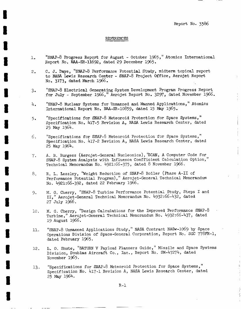
Report No. 3386
REFERENCES
1. "sNAP-8 Progress Report f o r August - October 2965 , I' Atomics I n t e r n a t i o n a l Report No. ~ ~ ~ - s ~ - 1 1 6 9 2 , dated 29 December 1965.
C. J. Daye, "SNAP-8 Performance P o t e n t i a l Study, midterm t o p i c a l r epor t t o NASA L e w i s Research Center - s~Ap-8 Projec t Office, Aerojet Report No. 3173, dated March 1966.
2.
3.
4.
5.
6.
7 .
a.
9.
10.
11.
12.
"SNAP-8 E l e c t r i c a l Generating System Development Program Progress Report f o r J u l y - September 1966," Aerojet Report No. 3297, dated November 1966.
"SNAP-8 Nuclear Systems f o r Unmanned and Manned Applicat ions, " Atomics Internat ional , Report No. NU-SR-10859, dated 15 May 1965.
"Specif icat ions f o r SNAP-8 Meteoroid Protect ion f o r Space Systems, 'I Speci f ica t ion No. 417-5 Revision A, NASA Lewis Research Center, dated 25 May 1964.
"Specif icat ions f o r SNAP-8 Meteoroid Pro tec t ion f o r Space Systems, Spec i f ica t ion No. 417-2 Revision A , NASA Lewis Research Center, dated 25 May 1964.
A . B. Burgess (Aerojet-General Nucleonics), %CAN, A Computer Code f o r SNAP-8 System Analysis w i t h I n f h e n c e Coeff ic ien t Calculat ion Opt ion, 'I Technical Memorandum No. 492~66-375, dated 8 November 1966.
R. L. Lessley, 'weight Reduction of SNAP-8 Boiler (Phase A - I 1 of Performance P o t e n t i a l Program), " Aerojet-General Technical Memorandum No. 4921:66-392, dated 22 February 1966.
M. G. Cherry, "SNAP-8 Turbine Performance P o t e n t i a l Study, Steps I and 11, 'I Aerojet-General Technical Memorandum No. 4932:66-432, dated 27 Ju ly 1966.
M. G. Cherry, "Design Calculat ions f o r t h e Improved Performance SNAP-8 Turbine, 19 August 1966.
Aerojet-General Technical Memorandum No. 4932:66-437, dated
"SNAP-8 Unmanned Applications Study, Operations Division of Space-General Corporation, Report No. SGC 778FR-1, dated February 1965.
NASA Contract NASw-1069 by Space
L. 0. Shute, "SATURN V Payload Planners Guide," Missi le and Space Systems Division, Doublas A i r c r a f t Co., Inc. , Report No. SM-47274, dated November 1965.
"Specif icat ions f o r SNAP-8 Meteoroid Pro tec t ion f o r Space Systems, 'I Speci f ica t ion No. 417-1 Revision A , NASA Lewis Research Center, dated 25 May 1964.
R - 1
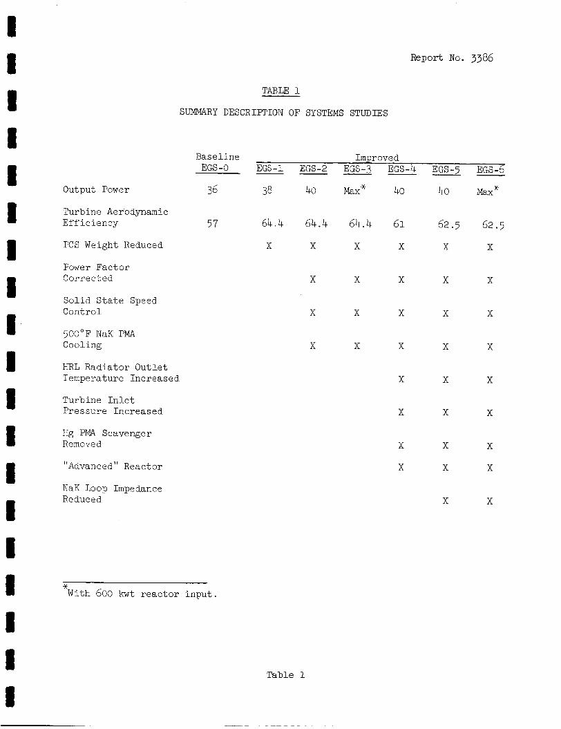
Output Power
Turbine Aerodynamic Eff ic iency
PCS Weight Reduced
Power Factor Corrected
Solid. S t a t e Speed Control
500°F N a K PMA Cooling
HRL Radiator Outlet Temperature Increased
Turbine I n l e t Pressure Increased
Hg PMA Scavenger Removed
"Advanced " Rea c t or
N a K Loop Impedance Re due e d
Report No. 3386
TABLE 1
SUMMARY DESCRIPTION OF SYSTEMS STUDIES
Baseline Improved EGS-1 EGS-2 EGS-3 EGS-4 EGS-5 EGS-6 ------ EGS -0
36 38 40 Max* 40 40 Max*
64.4 64.4 64.4 61 62.5 62.5
X X X X X X
57
* With 600 k w t r eac to r i npu t .
Table 1
X
X
X
X
X
X
X X
X X
X X
X X
X X
X X
X x
X
X
X
X
X
X
X
X
X
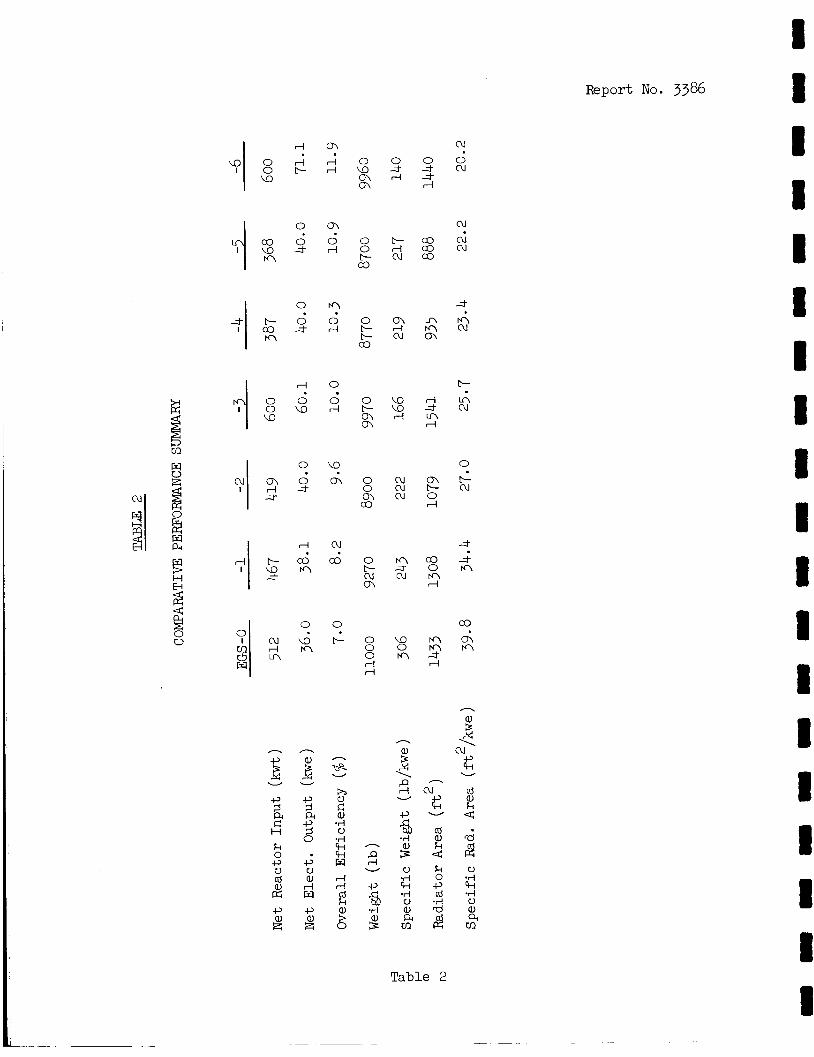
Report No. 3386
I o n
n W
+Y cu
G W
(d a, k 4
H 5 (d 0) k
3 0
4 .tJ V al rl w PI *;
al A cn d
Table 2
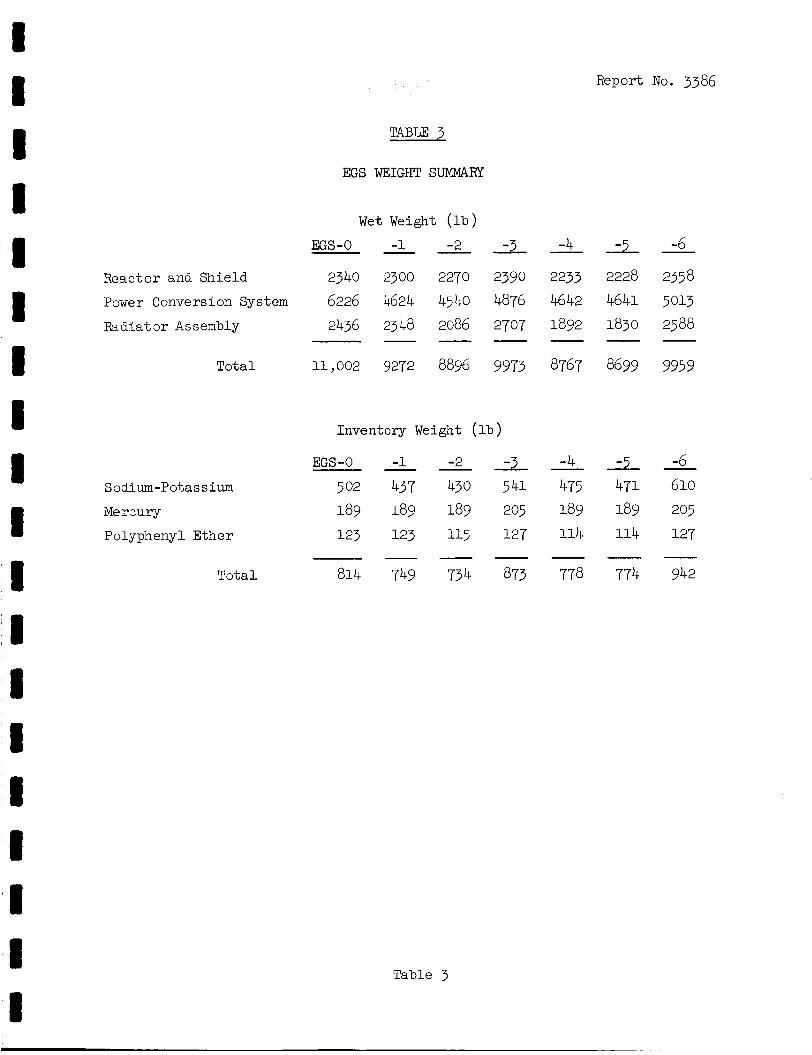
I 8 I I I I I 8 I I 1 1 1 I 1
i
Report No. 3386
TABLE 3
EGS WEIGHT SUMMARY
Wet Weight ( l b )
ms-0 - -1 -2 -3 -4 -5 - 6 Reactor and Shie ld 2340 2300 2270 2390 2233 2228 2358
Radiatar Assembly 2436 2348 2086 2707 1892 1830 2588
Tota l 11,002 9272 8896 9973 8767 8699 9959
Power Conversion System 6226 4624 4540 4876 4642 4641 5013
- - - - - -
Inventory Weight (lb )
EGS-0 --23!--4-5: -1 6 Sodium-Potassium 502 437 430 541 475 471 610 Merzury 189 189 189 205 189 189 205
Polyphenyl Ether 123 123 115 127 114 114 127
Tota l 814 749 734 873 778 774 942 - - - - - -
Table 3
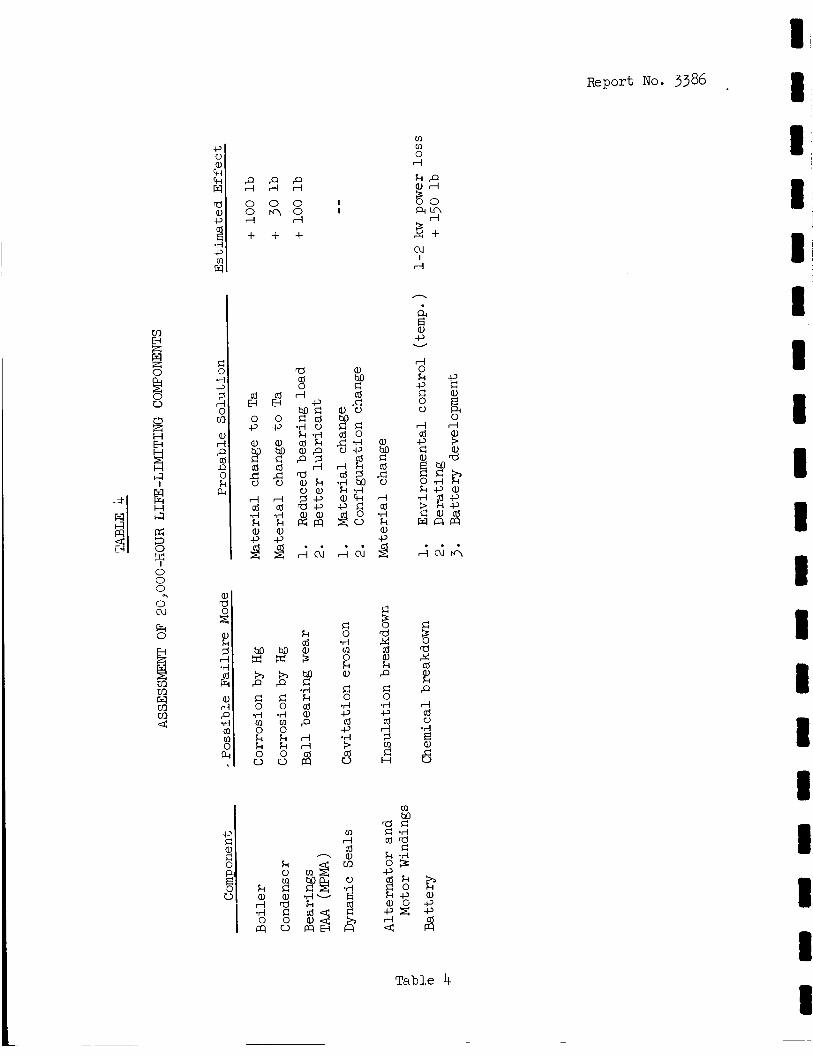
ft 0 0 rl
+
cd E4 0 -P
e,
cd 8 4 rl cd .rl k a, -P
9
ho x h P c 0 .rl m 0 k k 0 V
5 0 K\
+
E2
z 4
0 -P
a,
cd
rl cd “rl k a,
f
ho X h P c 0 .rl [I] 0 k k 0 V
k e,
I I
. . . rlcun
Table 4
Report No. 3386
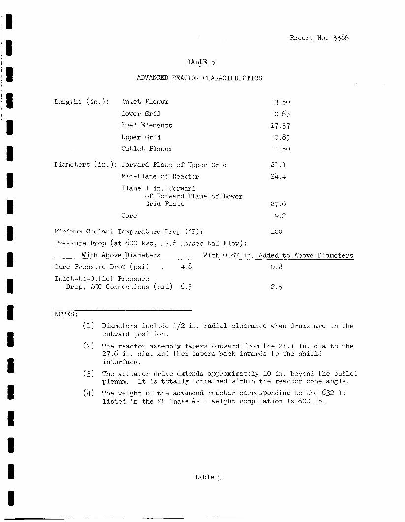
Report No. 3386
TABU 5
ADVANCED REACTOR CHARACTERISTICS
Lengths ( i n . ) : I n l e t Plenum
Lower Grid
Fuel Elements
Upper Grid
Out le t Plenum
3.50 0.65
17.37 0.85 1.50
Diameters ( i n . ) : Forward Plane o f Upper Grid 2 1 . 1
Mid-Plane of Reactor 24.4 Plane 1 i n . Forward
of Forward Plane of Lower Grid P l a t e 27.6
Core 9.2
Minimum Coolant Temperature Drop (OF) : 100
Pressure Drop ( a t 600 kwt, 13.6 lb / sec N a K Flow):
With Above Diameters With 0.87 i n . Added t o Above Diameters
Core Pressure Drop ( p s i ) 4.8 0.8 I n l e t -t o -Out l e t Pres sure
Drop, AGC Connections ( p s i ) 6.5 2 .5
NOTES :
(1)
( 2 )
Diameters include 1/2 i n . radial clearance when drums are i n t h e outward pos i t i on .
The r eac to r assembly tapers outward from t h e 21 .1 i n . d i a t o t h e 27.6 i n . d ia , and then t a p e r s back inwards t o the s h i e l d i n t e r f a c e .
The ac tua to r d r ive extends approximately 10 i n . beyond t h e o u t l e t plenum. It i s t o t a l l y contained wi th in t h e r eac to r cone ang le .
The weight of t h e advanced r e a c t o r corresponding t o t h e 632 lb l i s t e d . i n t he FF Phase A - I 1 weight compilation i s 600 l b .
(3)
(4)
Table 5

Report No. 3386
I! I
11 TABLE 6
SUMMARY OF VAPOR-CHAMBER FIN RADIATOR DESIGN DATA
Input : heat re jec ted 377,m NaK AT 660 F - 488OF armor r a t i o 0.25 vapor chamber surv iva l r a t i o 0. go surface emissivi ty 0.90
cy l indr ica l r ad ia to r , rad ia t ing outside only - diameter 9 f e e t
Nun-ber Outer Surface Total Radiator Radiator Radiator1J2 Area, One No. of Tube I D Length Area Weight of
No. Tubes Chamber ( i n . 2 ) Chambers ( i n . ) ( f t ) ( f t 2 ) ( l b ) - 1
2
3 4 5 6
7 8 9 10
150
15 0 125
3-25 LOO 100
80
80
50 50
80
40
80 40
80
80
80
40
40
40
1225
2447
1257
2514
1295
2587
1330 2656
2800
1400
.181 ,181 194
.194 * 211
.211
.230
.230
.276
.276
27- 9 27.8
28.0
28.0
28.2
28.2
28.5
28.5
29.2
29.2
788 785 790
790
796 796 804
804
825
825
1766 1653 1666
1553 1572
145 7 1500
1381
1289
1403
1. Weight includes tubes and armor, f i n s , headers, ducts, and armor, and a l s o includes the f l u i d inventory (NaK).
400-500 l b of s t i f f en ing s t ruc tu re i s required with the tube and f i n t o support the PCS, and t h e reac tor -sh ie ld combination. chamber f i n r ad ia to r may require l e s s addi t iona l s t ruc tu re due t o i t s be5te r s t r x t u r a l r i g i d i t y .
20 The vapor
Table 6
R I I I I i I R 1 8 I 8 I I 1 I i
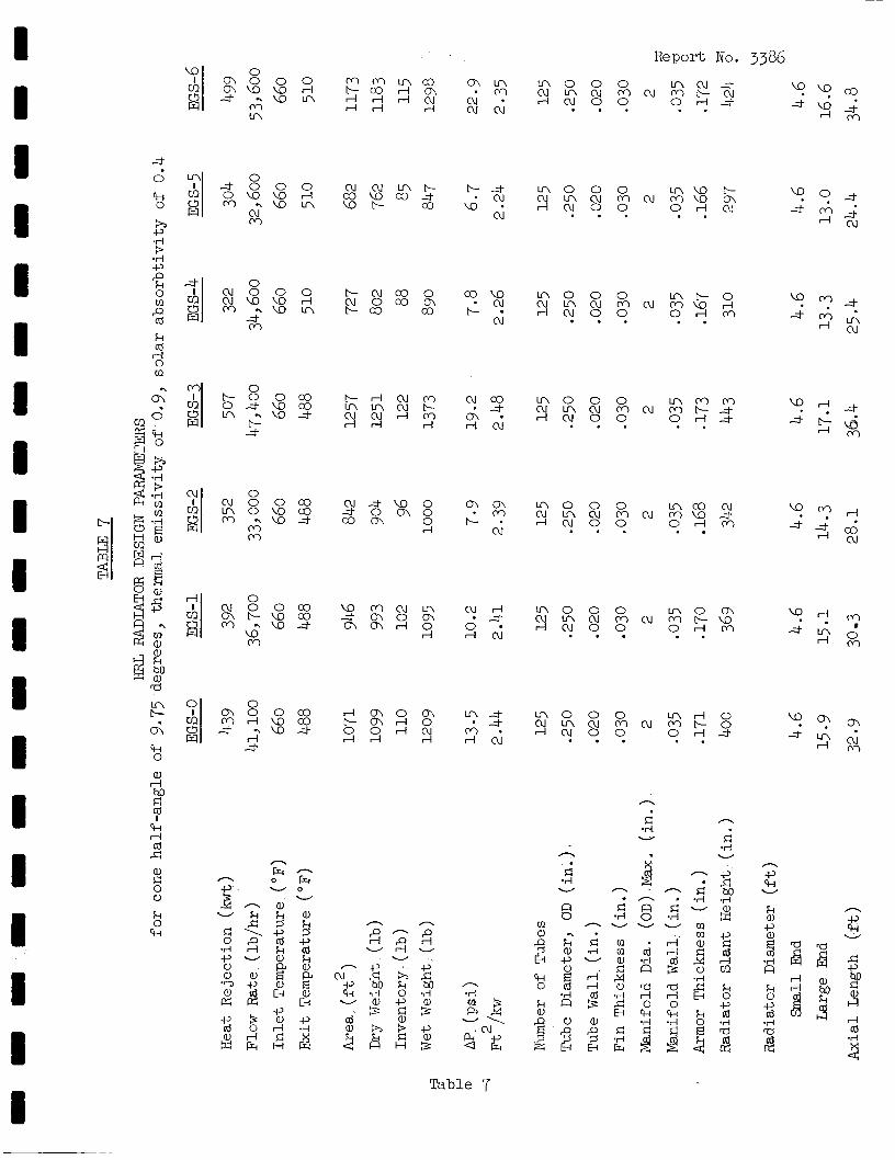
I I I I 1 I 1 I I 1 U B I I I I I I D
0 0 0 0 r - c u c o o c o w n o 0 0 n c - 0 w w r l c u o c o c h - c u c u n c u m c u m w r l
O r l M . . - u n c-03 co t-• r l c u o o . . . -% cu
" ? M
4 % f l n
Table ' I
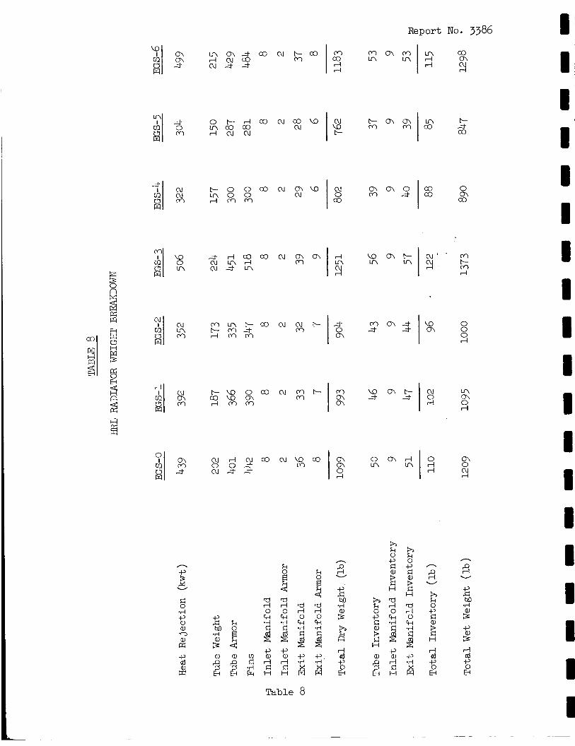
Report No. 3386
I I I I I I I
0 M " ""91% co
I rl
n
ft W
n
ft W
a rl 0
a .A
rl 0 k *d
; H 2 -P a, rl r: H
-P e, rl d H
rl cd -P
r2
rl cd +J 0 E-l
n, x i3 e
5
Table 8
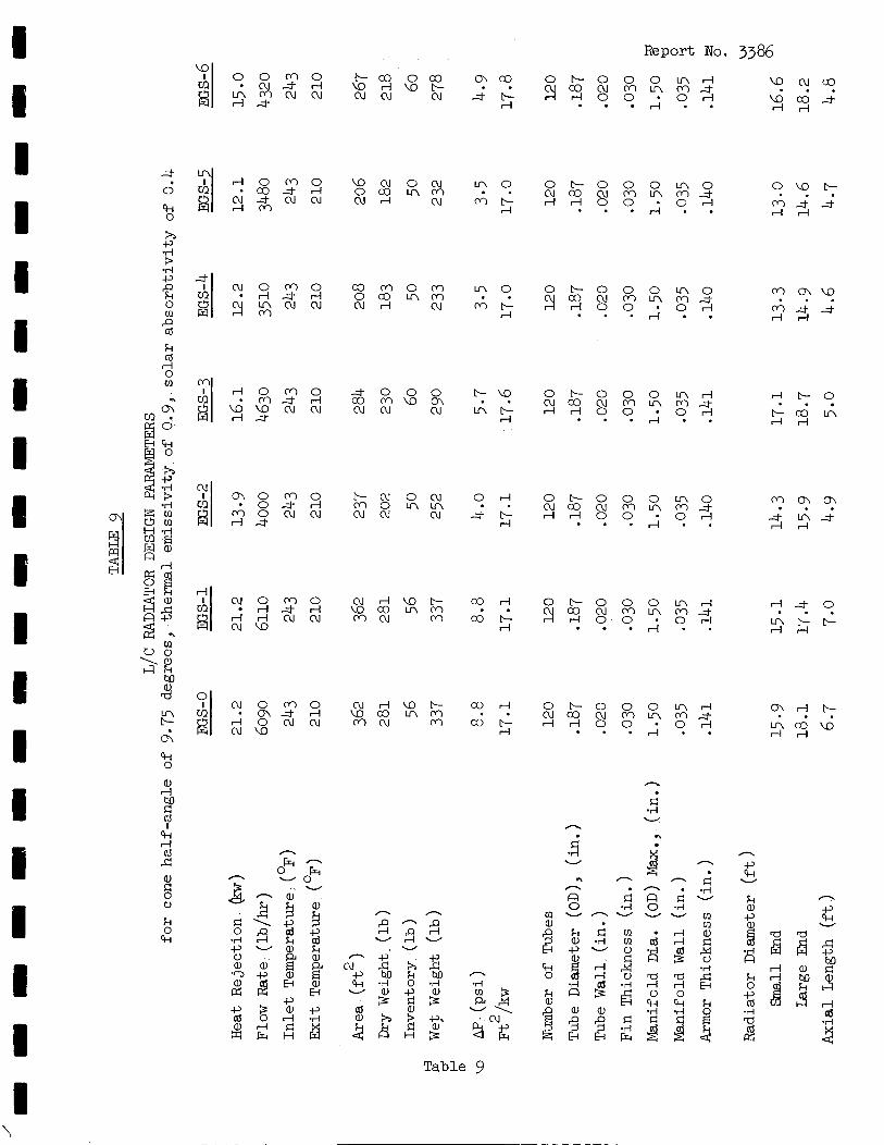
I 1 I I I I I I 1 E 1 c I I I Q I 1 I
\
Report No. 3386
o w t -
r l r l G ; t L ;
x -P -rl
r l t - 0
r l r l C G IA
81 c u o m o c n 3 rl r l o c u c u c u w
c o d c o r -
rl
. . O F - O O O L n r l c u c o C U M L n r n ~ r l r l o o * o r l 0 ' r l t -
meow r l r l
. . . . . . J . .
Ts.
F: .rl W
n n c .
.;i W
n h
n - n . r:
.rl W
A
-P (H W k
0 %I
a,
2 (H 0
rl rl
9
2 2 m a r l r l 0 0
r: .rl W
. . W
rl rl
rl rl n k
0 -cr, cd
.rl a 2
a,
h s c
Fr .rl 3 3
Table 9
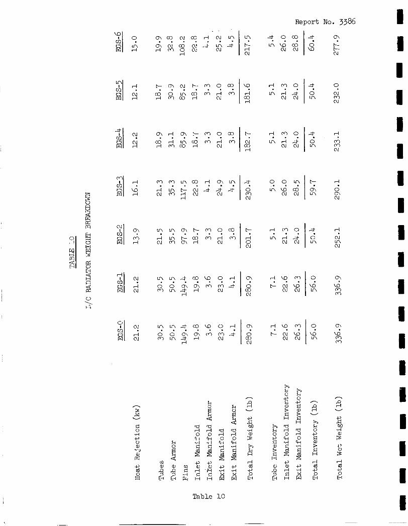
1 1 I I I 1 1 I 1 1 I 3 I 1 3 I I I I
O O L n
n w c o c u c u . . . .
Report No. 3386
In 3 0 m . . .
t- m In
r l W M
r - c u w c u c u . . . 0
w In
m c o c u c o r l cu tn C h c u c o c u L f ~ A r l M O c u cu . . . . . . .
rl
y ? y c - M o c o . . . . co 0 I n c o M r l M rl M c o rl cu
w r l M O
rl Inr ld co c u c u rl
. . . 0 0 cu In M cu
1 cu
M M L n c o r l O \ I n l ; f . . . . . . .
A M 0
I n r l ; t c u c u . . . 3
0 In
V '\
b.2
m 0 co cu
0 w In
n
f; W
k 0
$ n
f; v
a rl 0 k Ti
9
a rl 0 k .d
4 k
.! rl ld f, 0 5
m e, P 9 5
rl ai -P 0
€4
L3 c, a, ';I
E: H
a,
€i 9 x
4 x i$
Table 10
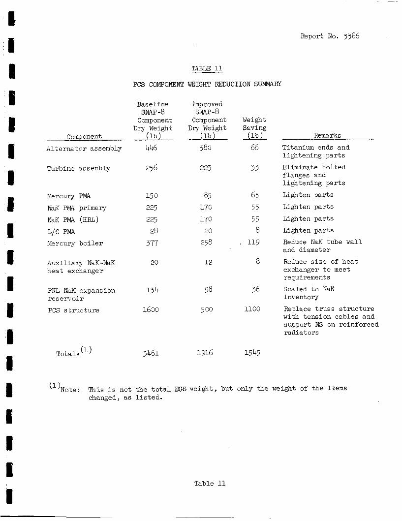
Report No. 3386
TABLE 11
PCS COMPONENT WEIGHT REDUCTION SUMMAHY
Baseline
Component D r y Weight
446
SNAP-8
Component 0 A 1 t e ma t o r assembly
Turbine assembly 256
Mercury PMA 15 0 NaK PMA primary 225
NaK PMA ( H F G ) 225 L/C PMA 28 Mercury b o i l e r 377
Auxi l ia ry NaK-NaK 20 h e a t exchanger
PNL NaK expansion 134
PCS s t r u c t u r z 1600 r e s e l v o i r
Tota ls (1) 3461
Imp roved
Component D r y Weight
SNAP-8
0 380
223
85 170 170 20
25 8
12
98
500
1916
Weight
ZT 66
33
65 55 55 8
119
8
36
1100
15 45
Remarks
Titanium ends and l igh ten ing p a r t s
Eliminate b o l t e d f langes and l i gh ten ing p a r t s
Lighten p a r t s
Lighten p a r t s
Lighten p a r t s
Lighten p a r t s
Reduce NaK tube w a l l and diameter
Reduce s i z e of h e a t exchanger t o meet requirements
Scaled t o NaK invent ory
Replace t r u s s s t r u c t u r e with t ens ion cables and support NS on re inforced r ad ia to r s
( l )No te : This i s not t h e t o t a l EGS weight, bu t only the weight of t he i t e m s changed, as l i s t e d .
Table 11
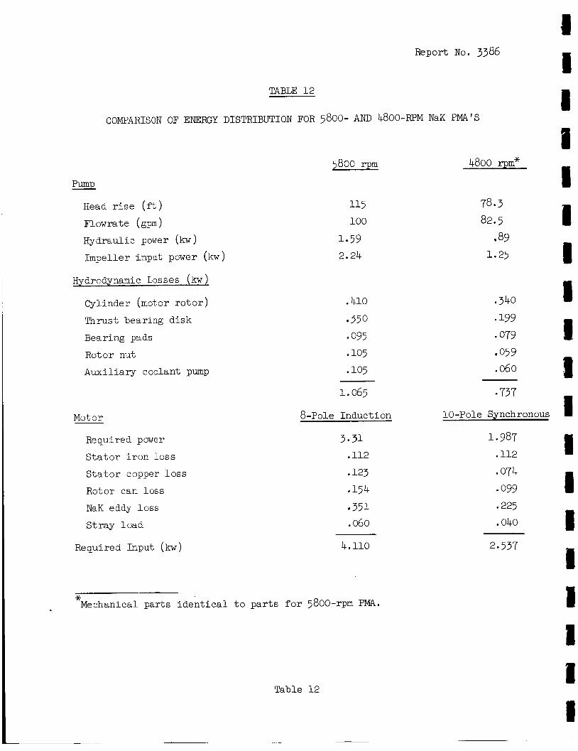
Report No. 3386
TABLE 1 2
COMPARISON OF ENERGY DISTRIBUTION FOR 5800- AND 4800-RPM NaK PMA'S
pump Eead r i s e (f't)
Flowrate (gpm)
Hydraulic power (kw)
Impel ler input power (kw)
Hydrodynamic Losses (kw 1 Cylinder (mot80r r o t o r )
Thrust bearing d i sk
Bearing pads
Rotor nut
A,uxiliary coolant pump
5800 rpm
115 100
1.59 2.24
.410 350
* 095 105
.io5
4800 rpm*
78.3 82.5
89 1.25
,340 * 199 079 059
.060
Motor
Required power
S t a t o r i r o n loss
S t a t o r copper loss
Rotor can loss
NaK eddy loss
St ray load
1.065 9 737
8-pole Induct ion
3-31 .112
.123
.154 351
.060
10 -Pole Synchronous
1.987 .112
.074 099
.225
.040
R e qu i red Icput ( kw ) 4.110 2.537
~ * Mechanical par t s i d e n t i c a l t o p a r t s for 5800-rpm PMA.
Table 12
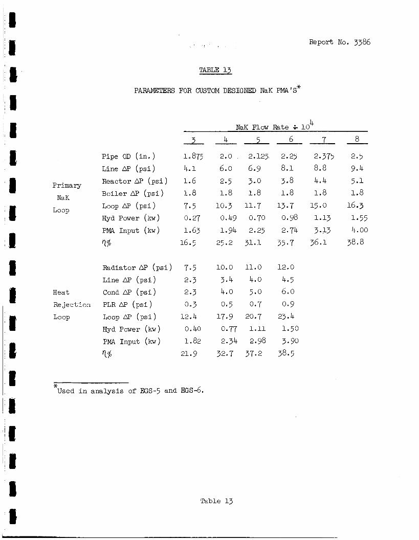
Report No. 3386
TABLE 13
PARAMETERS FOR CUSTOM DESIGNED NaK PMA'S*
4 NaK Flow Rate 4 10
- 4 5 7 a Pipe OD ( i n . ) 1.875 2.0 2.125 2.25 2.375 2.5 Line DP ( p s i ) 4.1 6.0 6.9 8.1 a. a 9.4 Reactor AP ( p s i ) 1.6 2.5 3.0 308 4.4 5.1 Boi l e r AP ( p s i ) 1.8 1.8 1.8 1.8 1.8 1.8
LOOP H ( p s i ) 7.5 10.3 11.7 13.7 15.0 16.3 Hyd Power (kw) 0.27 0.49 0.70 0.98 1.13 1.55
T% 16.5 25.2 31.1 35.7 36.1. 38.8
Primary
NaK
Loop
PMA Input (kw) 1.63 1.94 2.25 2.74 3.13 4.00
Radiator AP ( p s i ) 7.5 10.0 11.0 12.0
Line AF' ( p s i ) 2*3 3.4 4.0 4.5
Rejection PLR AF' ( p s i ) 0.3 0.5 0.7 0.9 Heat Cond AP ( p s i ) 2.3 4.0 5.0 6.0
Loop LOOP ( p s i ) 12.4 17.9 20.7 23.4 Hyd Power ( k w ) 0.40 0.77 1.11 1.50
1% 21.9 32.7 37.2 38.5 PMA Input (kw) 1.a2 2.34 2.98 3.90
* Used i n a n a l y s i s of EGS-5 and EGS-6.
Table 13
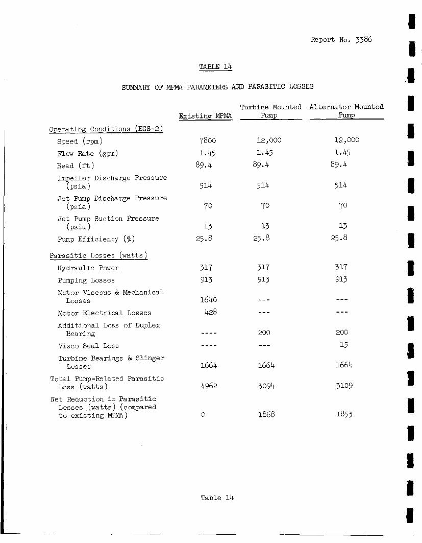
Report No. 3386
TABLE 14
SUMMARY OF MPMA PARAMETERS AND PARASITIC LOSSES
Turbine Mounted Al t e rna to r Mounted Exis t ing MPMA pump pump
Operating Conditions (EGS-2) Speed (rpm)
Flow Rate (gpm)
Head ( f t )
Impel ler Discharge Pressure
Jet Pump Discharge Pressure
J e t Pump Suction Pressure
Pump Eff ic iency ($I)
(psis)
(psis 1
(psis 1
P a r a s i t i c Losses ( w a t t s )
Hydraulic Power
Pumping Losses
Motor Viscolds & Mechanical Losses
Mctor E l e c t r i c a l Losses
Addit ional Loss of Duplex
Visco Sea l Loss
TuTbine Bearings & S l i n g e r
To ta l Pump -Re l a t e d Paras it i c LOSS ( w a t t s )
Net Reduction i n P a r a s i t i c Losses ( w a t t s ) (compared t o e x i s t i n g MPMA)
Bearing
Losses
7800 1.45 89.4
51.4
70
13 25.8
317 913
1640 428
---- ----
1664
4962
0
Table 14
12,000
1.45 89.4
5 14
70
13 25.8
317 913
--- ---
200 ---
1664
3094
1868
12,000
1.45 89.4
514
70
13 25.8
317 913
--- ---
200
15
1664
31.09
1853
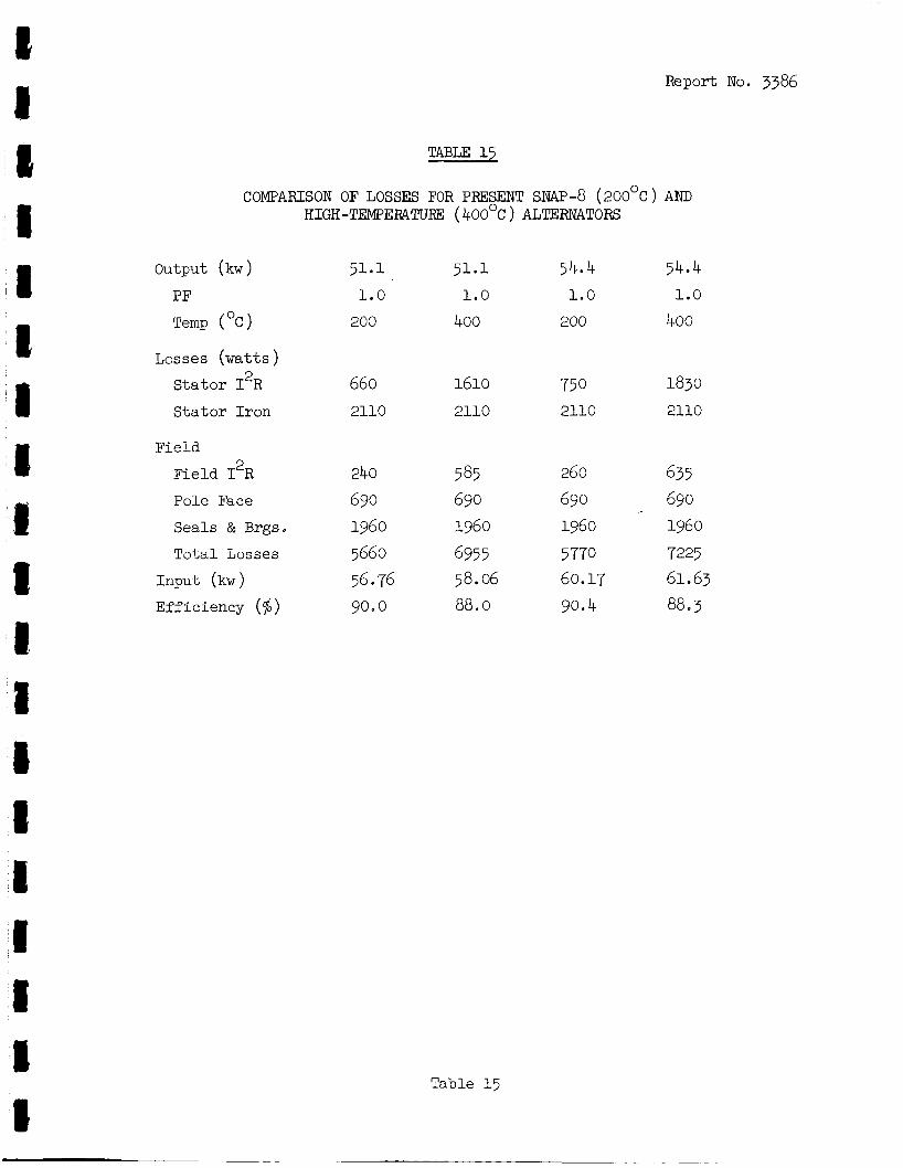
Report No. 3386
TABLE 15
COMPARISON OF LOSSES FOR PRESENT SNAP-8 ( 2OO0C ) AND HIGH-TEMPERATURE ( 4OO0C ) ALTERNATORS
Output (kw ) 51.1 51.1 54.4 54.4 PF 1.0 1.0 1.0 1.0
Temp ("C) 200 400 200 400
Losses (watts ) 660 1610 750 1830 S ta to r I R
S t a t o r I ron 2110 2110 2110 2110
2
Field
Field 12R 240 585 260 635 Pole Face 690 690 690 690 Seals & Brgs. 1960 1960 1960 1960
Input (kw ) 56-76 58.06 60.17 61.63 Efficiency (%) go. 0 88.0 90.4 88.3
T o t a l Losses 5660 6955 5 770 7225
Table 15
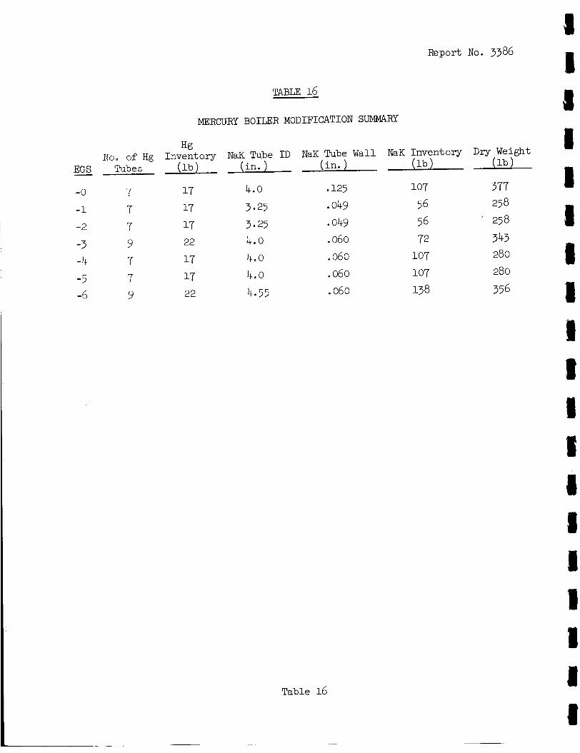
Report No. 3386
TABLE 16
MERCURY BOILER MODIFICATION SUMMARY
Hg No. of Hg Inventory NaK Tube I D NaK Tube Wall NaK Inventory D r y Weight 0 ( i n . ) ( l b ) EGS Tubes ( l b ) ( i n . ) -
107 377 -0 7 17 4.0 .125
-1 7 1.7 3.25 -2 7 17 3-25 e 049 56 ’ 258
-3 9 -4 7 17 4.0 e 060 -5 7 17 4.0 .060
.049 56 258
22 4.0 .060 72 343 107 280 107 280
.060 138 356 -5 9 22 4.55
Table 16
~
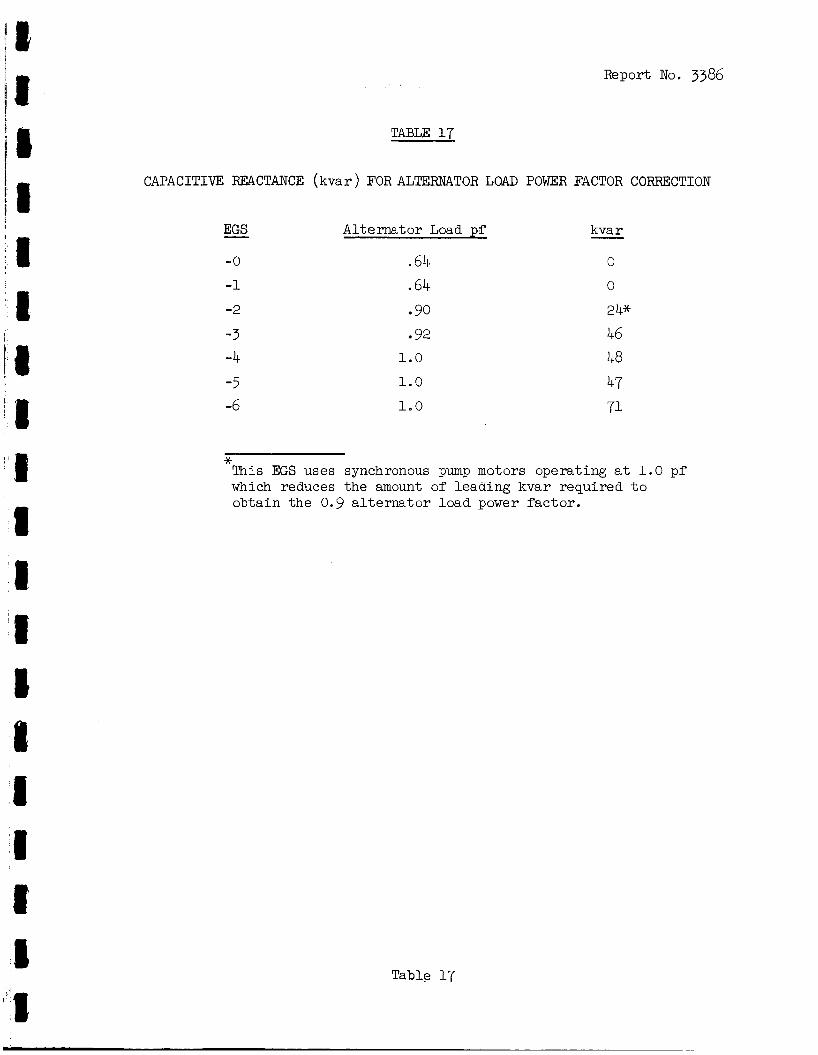
Report No. 3386
jl TABLE 17
CAPACITIVE REACTANCE (kvar ) FOR ALTERNATOR LOAD POWER FACTOR CORREXTION
-0
-1
-2
-3 -4 -5 -6
Alternator Load pS
64 .64 90 92
1.0
1.0
1.0
kva r - 0
0
24* 46 48 47 71
* This EGS uses synchronous pump motors operat ing a t 1.0 pf which reduces the amount of leading kvar required t o obta in the 0.9 a l t e r n a t o r load power f ac to r .
Table 17
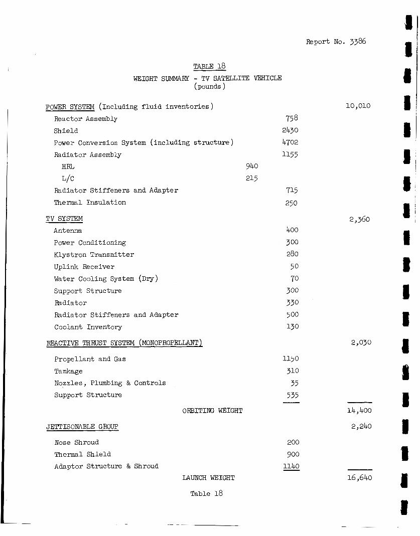
3 Report No. 3386
TABLE 18 WEIGHT SUMMARY - TV SATELLITE VEHICLE
(pounds )
10 > 010 POWER SYSTEM (Including f l u i d inventor ies ) React or Assembly
Shield
Power Conversion System ( including s t ruc tu re ) Radiator Assembly
HRL
L/C Radiator S t i f f ene r s and Adapter
Thermal Insu la t ion
75 8 2430 4702 11.55
940 215
715 250
2,360 TV SYSTEM
Antenna
Power Conditioning
Klystron Transmitter
Uplink Receiver
Water Cooling System (DV) Support Structure
Radiator
Radiator S t i f f ene r s and Adapter
Coolant Inventory
2,030 REACTIVE THRUST SYSTEM (MONOPROPELLANT)
1150
310 35 535 -
Propel lant and Gas
Tankage
Nozzles > Plumbing & Controls
Support Structure 1 14 400 ORBITING WEIGHT
2 240 JETTISONABLE GROUP
Nose Shroud
Thermal S'nielci
Adaptor Structure & Shroud
200
900 1140 -
16,640 LAUNCH WEIGHT
Table 18
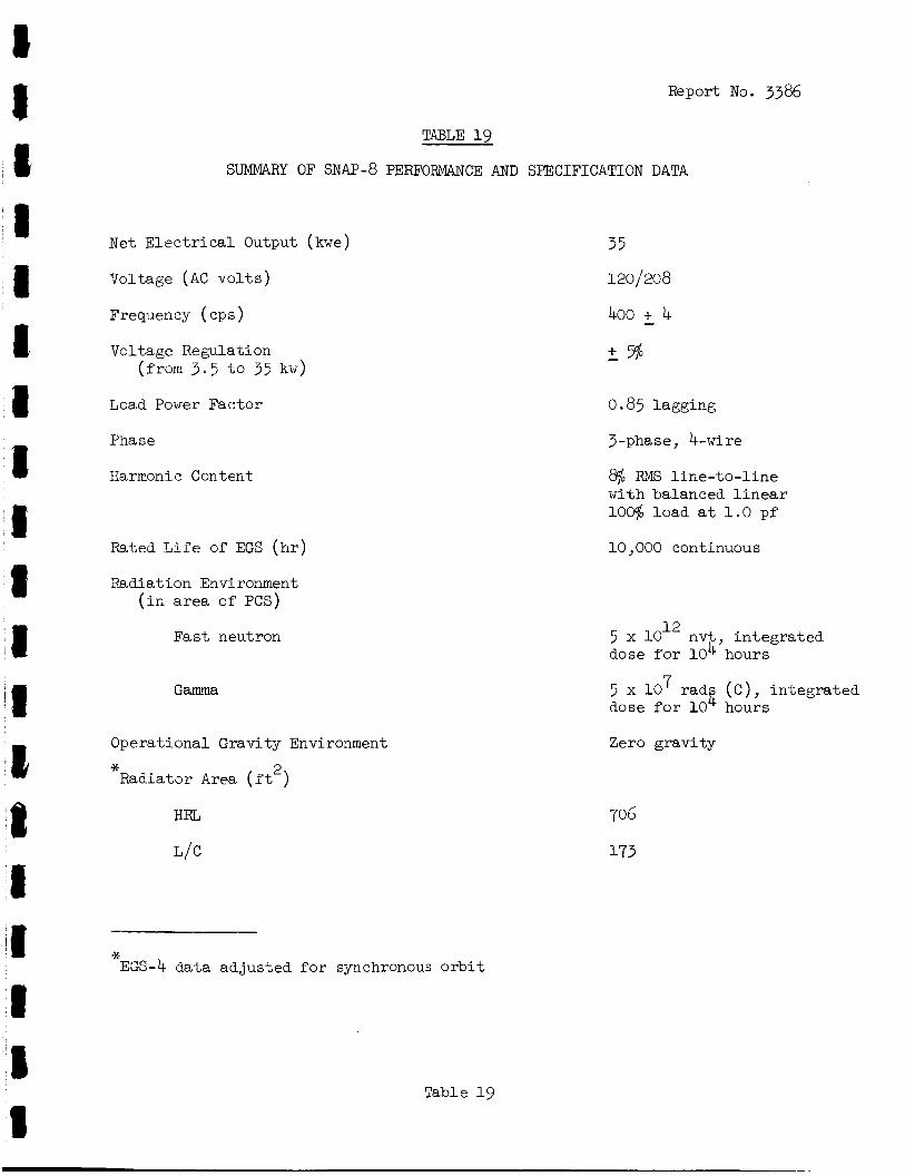
I C ' 1 1 1 1 1
Report No. 3386
TABLE 19
SUMMARY OF SNAP-8 PERFORMANCE AND SPECIFICATION DATA
Met E l e c t r i c a l Output (kwe)
Voltage (AC v o l t s )
Frequency ( cp s )
Voltage Regulation (from 3 . 5 t o 35 kw)
Load Power Factor
Phase
Harnronic, Content
Rated L i f e of EGS ( h r )
Radiation Enviroment ( i n area of PCS)
Fa s t neutron
Operat ional Gravity Environment
* 2 Radiator Area ( f t )
HRL
L/C
* EGS-4 da ta ad jus ted for synchronous o r b i t
Table 19
35
1201 208
400 + 4 - - + %
0.85 lagging
3-phase, b w i r e
8$o FMS l i n e - t o - l i n e with balanced l i n e a r 106 l oad a t 1.0 pf
10,000 continuous
5 x 10l2 nvt i n t eg ra t ed dose fo r 10 4' hours
5 x 10 7 radg ( C ) , i n t eg ra t ed dose for 10 hours
Zero gravi ty
706
173
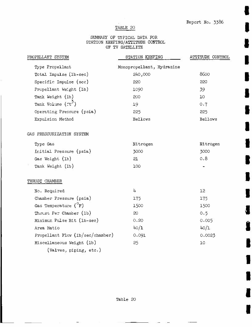
Report No. 3386 TABLE 20
SUMMABY OF TYPICAL DATA FOR STATION KEEPING/ATTITUDE CONTROL
OF TV SATELLITE
PROPELLANT SYSTEM
Type Propellant
Total Impulse ( lb - see )
Spec i f ic Impulse ( see )
Propel lant Weight ( l b )
Tank Weight ( l b ) 3 Tank Volume ( f t
Operating Pressure ( p s i a )
Expulsion Method
GAS PRESSURIZATION SYSTEM
Type Gas
I n i t i a l Pressure ( p s i a )
Gas Weight (lb)
Tank Weight ( lb )
THRUST CHAMBER
No. Required
Chamber Pressure ( p s i a )
Gas Temperature ( F)
Thrust Per Chamber ( l b )
Minimum Pulse B i t ( l b - see )
Area Ratio
Propel lant Flow (lb/see/ehamber)
_Miscellaneous Weight ( l b )
0
(Valves, piping, e t c . )
STATION KEEPING
Monopropellant, Hydrazine
240,000
220
1090
200
1 9 225 Bellows
Nitrogen
3000
21
100
4 175 1500
20
0.20
40/1
0.091
25
Table 20
~~~
ATTITUDE CONTROL
8600 220
39 10
0.7
225 Bellows
Nitrogen
3000
0 .8
12
175 1500
0.5 0.005
4011
0.0023
10
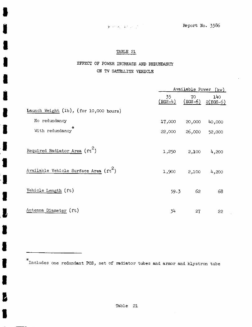
~
Report No. 3386
TABLE 21
EFFECT OF POWER INCREASE AND REDUNDANCY
ON Tv SATELLITE VEHICLE
Available Power (kw)
Launch Weight ( l b ) , ( f o r 10,000 hours)
No redundancy
With redundancy *
2 Required Radiator Area ( f t )
2 Available Vehicle Surface Area ( f t )
Vehicle Length ( f t )
Antenna Diameter ( f t )
35 (EGS-4)
17,000
22,000
l J 2 5 0
1,900
70 (EGS-6)
20 , 000
26, ooo
2,100
2,100
59.3 62
34 27
140 2 ( EGS -6 )
40,000
52 , 000
4 , 200
4,200
68
22
* Includes one redundant PCS, set of rad ia tor tubes and armor and k lys t ron tube
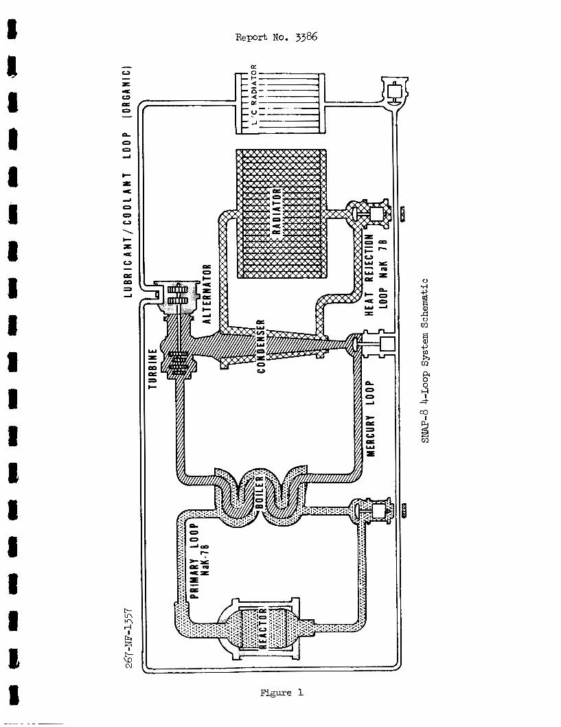
R e p o r t NO. 3386
I E-= I l r d
Figure 1
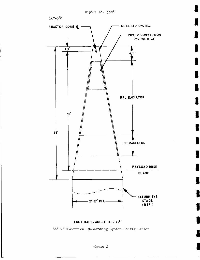
Report No. 3386
REACTOR
1 1. -
1
56'
COR E
-
NUCLEAR SYSTEM
POWER CONVERSION SYSTEM (PCS)
HRL RADIATOR
L/C RADIATOR
50'
I I I
\ \ \ PAYLOAD DOSE
I \ PLANE
STAGE ( REF. 1
CONE HALF - ANGLE = 9.75O
SNAP-8 E l e c t r i c a l Generating System Configuration
Figure 2
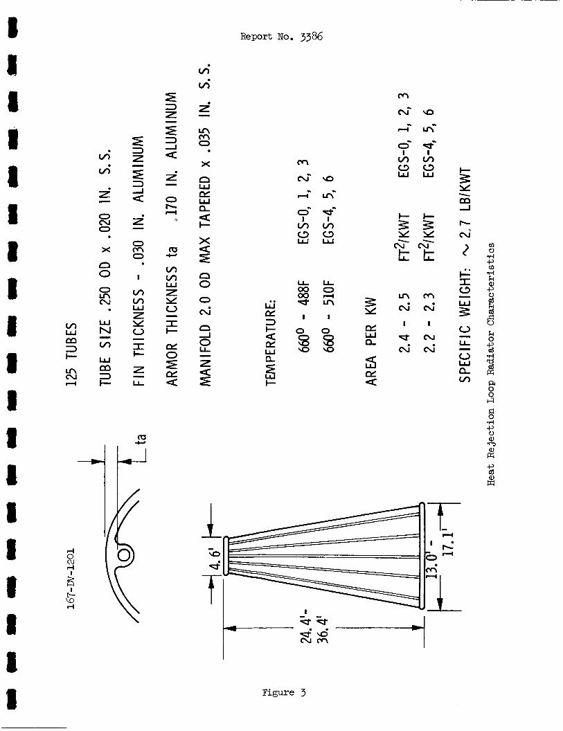
Report No. 3386
vi v;
M
cui
0- I vi z? P v) c3 W 2' -
m
vi vi
. x
i i - 0 cu 0
x .
0 b d 0- d
I I
cu- m 2 .E: t Q n 0
. I
v) v)
in .rl k aJ -P E (d
E s 0 - L
0 W e vi
-
. W N v)
W
3 I-
- m
PL I I 3 tn w z PL 5 % w e
0 I I-
- 7 - LL fa
0 0 GI
A
rl 0 cu r: !%
I t- v3 rl
flL- I I,.
I I --
Figure 3
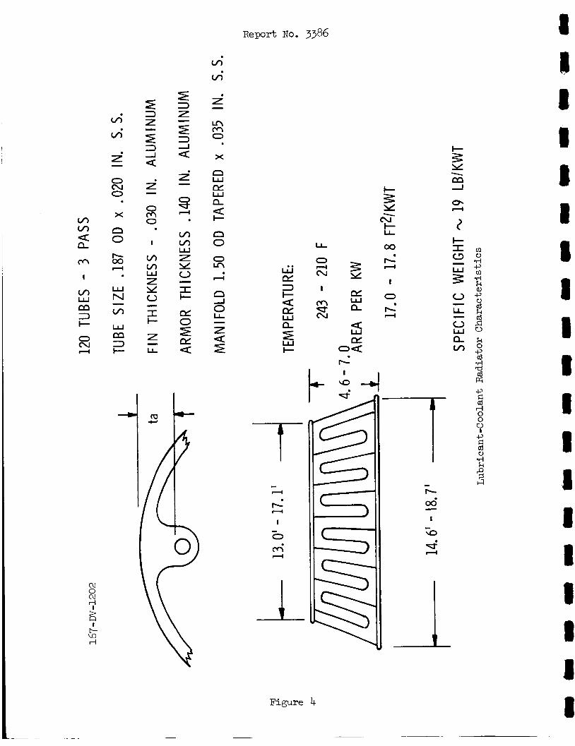
vi v;
- z 3 a
In M 0
i - X
i - n w i - s'
hd cu' L 00
W a,
5 8 0
X
LL
0 cv I
m'
d
x
s d
w N
w CY 3 I-
CY W LL
w I-
a
z
E q d VI
W m 3 +
s oa E
b I
- 4
a
7 -r - d
b A
I
0 - m' d
I cu 0 cu rl
c- UI rl
Figure 4
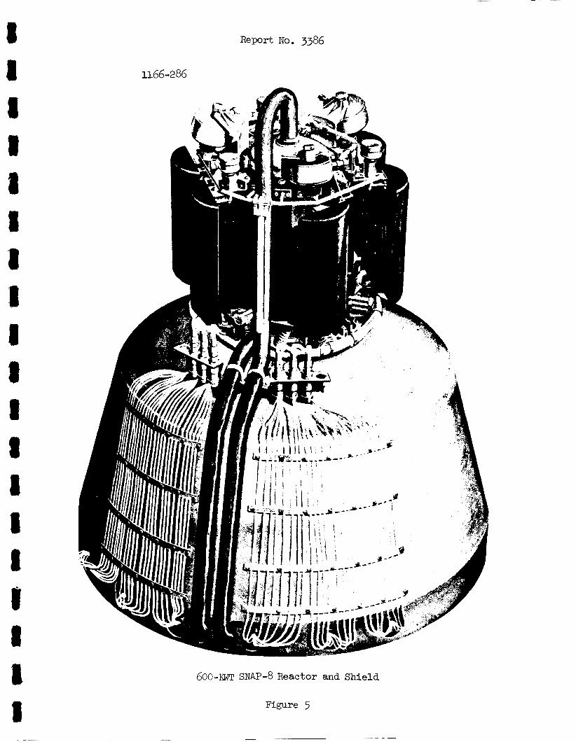
R e p o r t No. 3386
1166-286
600-XWT SNAP-8 Reactor and Shield
Figure 5
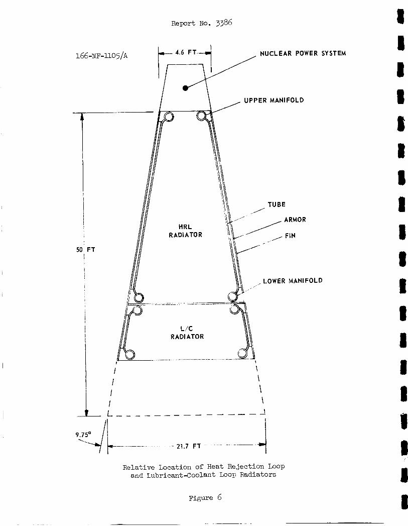
Report No. 3386 8 166 -NF-110 5/A NUCLEAR POWER SYSTEM
UPPER MANIFOLD
I- I
I 1 I
50 FT 1
I [
, LOWER MANIFOLD
I
I
! I
RADIATOR I
I \ I \
\ \
I 1 1 If I 8 I 1 8 I 8
I a
I Relative Location of Heat Rejection Loop and Lubricant-Coolant Loop Radiators
I Figure 6
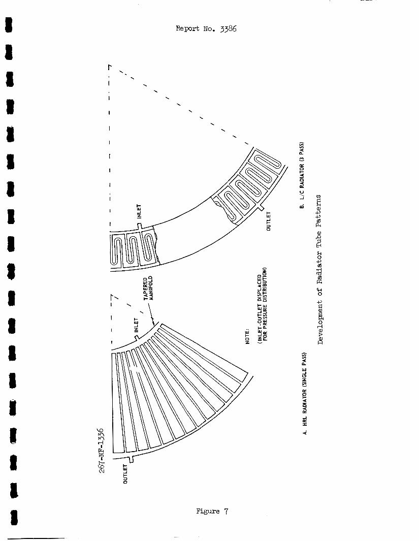
r I
I
I
I
I
I
I
I
I
I
I
R e p r t No. 3386
'. \
v) v)
4: n I* - E 0 I- 4:
4: E
- n
I \
I L
Figure 7
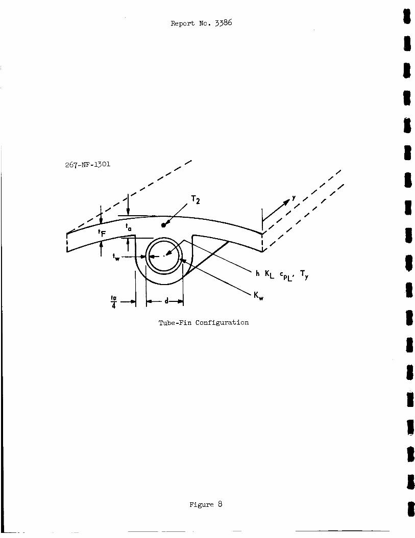
Report No. 3386
267 -NF - 13 01
0 /
0 0
/ /
/
/ /
/
Tube-Fin Configuration
8
1 8
m
Figure 8
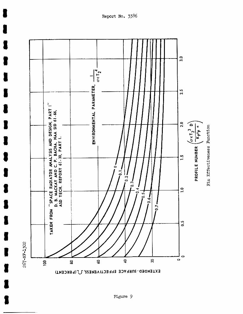
Report No. 3386
0 cv 0 * 0 0 0 Q) W z
Figure 9
x
0
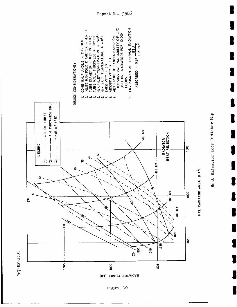
..
Report No. 3386
n 0 n rl I
Figure 10
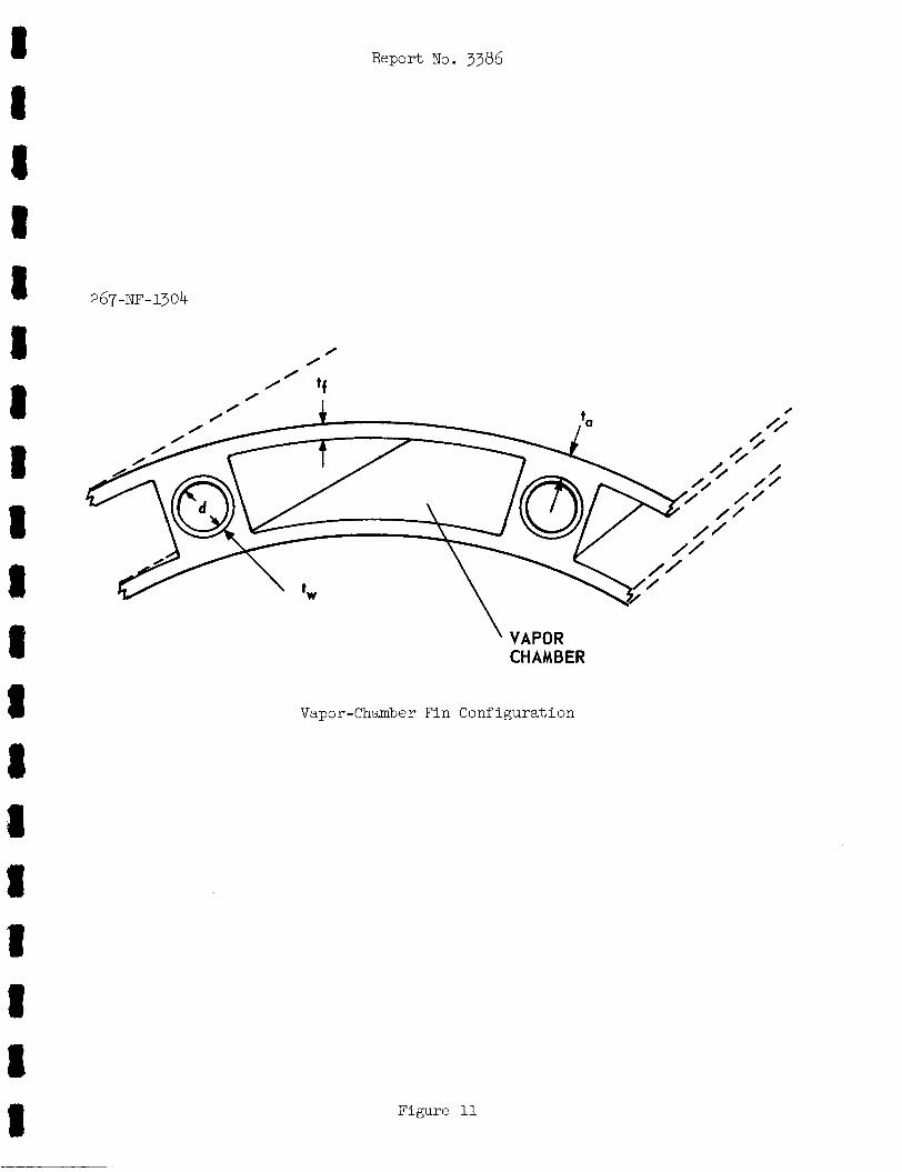
I I 1 8 I I
267-NF-1304
/ 0
/ ’ ‘f 0 I /’ 4
I II 8 8 CHAMBER
8 Vapor-Chamber Fin Configuration
8
1: 8 8 I 1
a
Figure 11
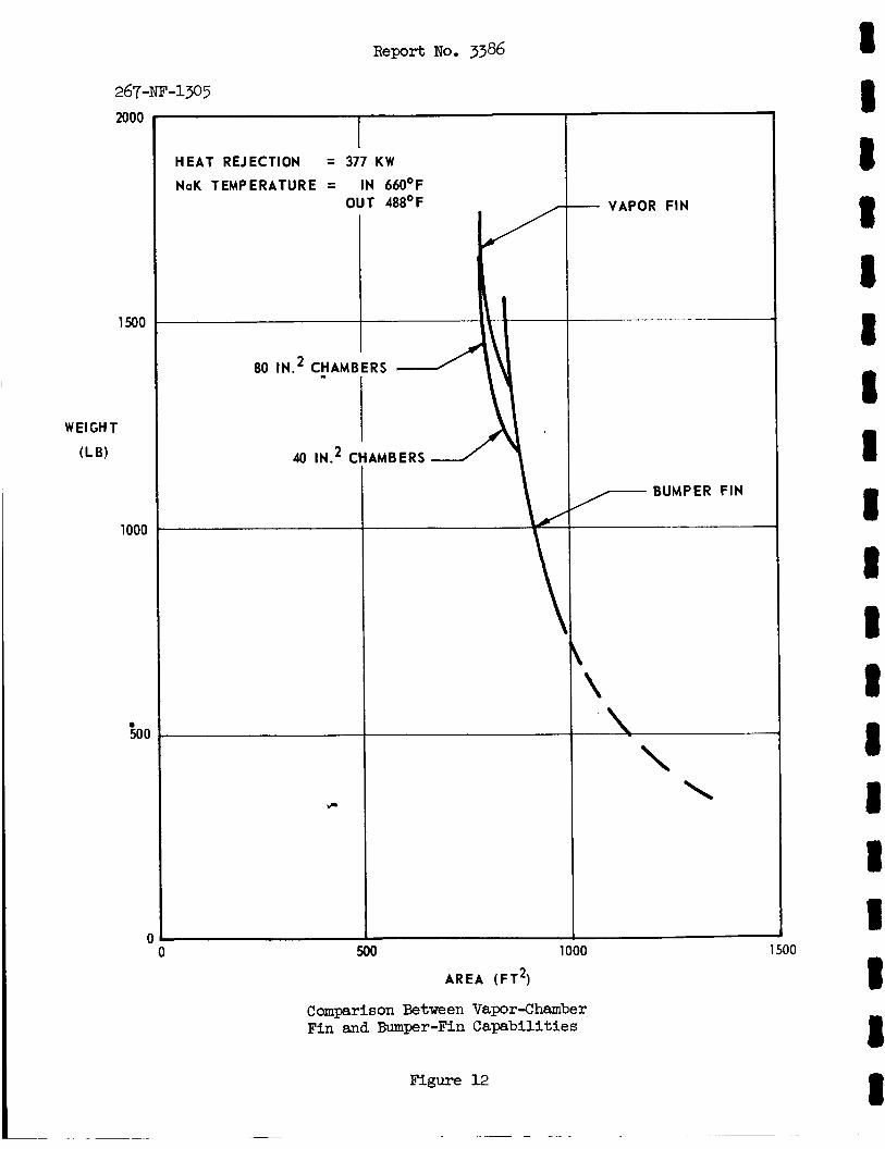
267-NE-1305 2000
1500
1000
500
c
I HEAT REJECTION = 377 KW
NaK TEMPERATURE = IN 66OOF
40 IN.2 CI
- VAPOR FIN
BUMPER FIN 7
\ \
500 1000
A R E A (FT*)
Camparison Between Vapor-Chamber Fin and Bumper-Fin Capabilities
Figure 12
1500
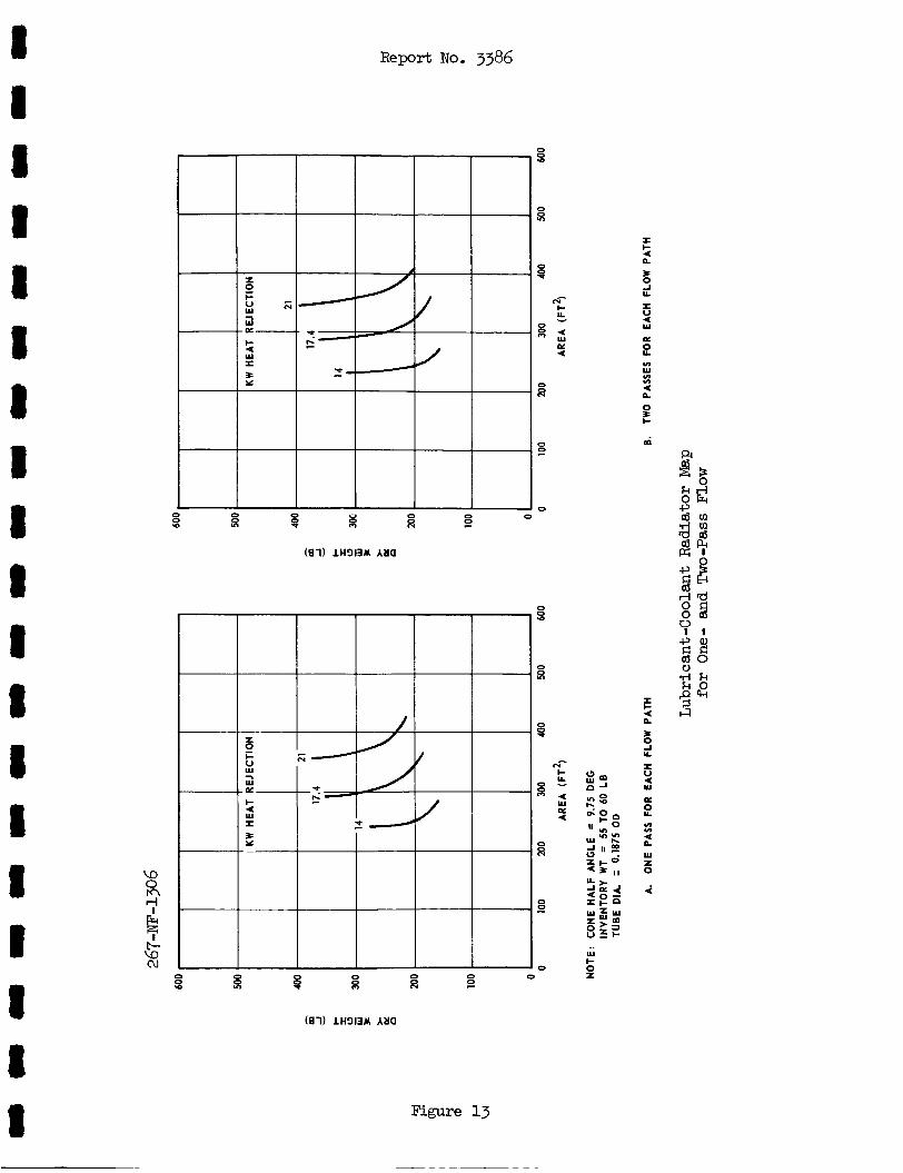
8 8 1 8 I 1 I 1 I 1 8 8 I I 1 I 8 I 1
Di I- 4. W I P Y
E 0 0 Y)
2 3
0 0 .a ji
Report No. 3386
i= Y
Figure 13
8 Y)
E
8 N- I- b
0 x::
E
Di 4
0 B
0
0 0 0
E
8 N- I-
4 " : W
0: 4.
ii
0 0
a 0
I I- 4 n 3 0 J LL
I u 4 W
I
B v)
W v) v)
4.
0 n
E ai
B 0 J LL
I u 4. W
I
P v) v)
4 n
i
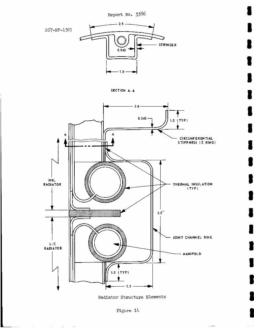
Report NO. 3386
2.5
2 6 7 - ~ F - 1307
STRlN GE R 0.040 *
1-1
SECTION A-A
A
RAD1 H I i RL ATOR
I T L/C
I RADIATOR
3.0-4
0.040 1 - CI RCUMFER EN TI AL STIFFNESS (Z RING)
THERMAL INSULATION ( T Y P )
JOINT CHANNEL RING
MAN1 FOLD
Radiator Structure Elements
Figure 14
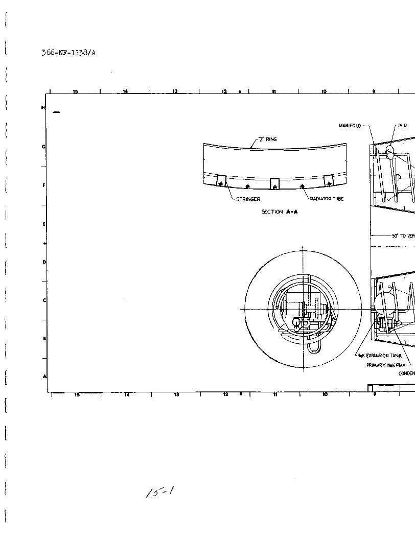
3 66 -NE- ii38/A
H
- .I)
MANIFOLD -
r'Z' RING
7 rPLR
STRINGER \RADIATOR TUBE
YCTION A-A
I O E N A
I I I I 1s I 14 I 13 I 12 * I 11 I 10 I
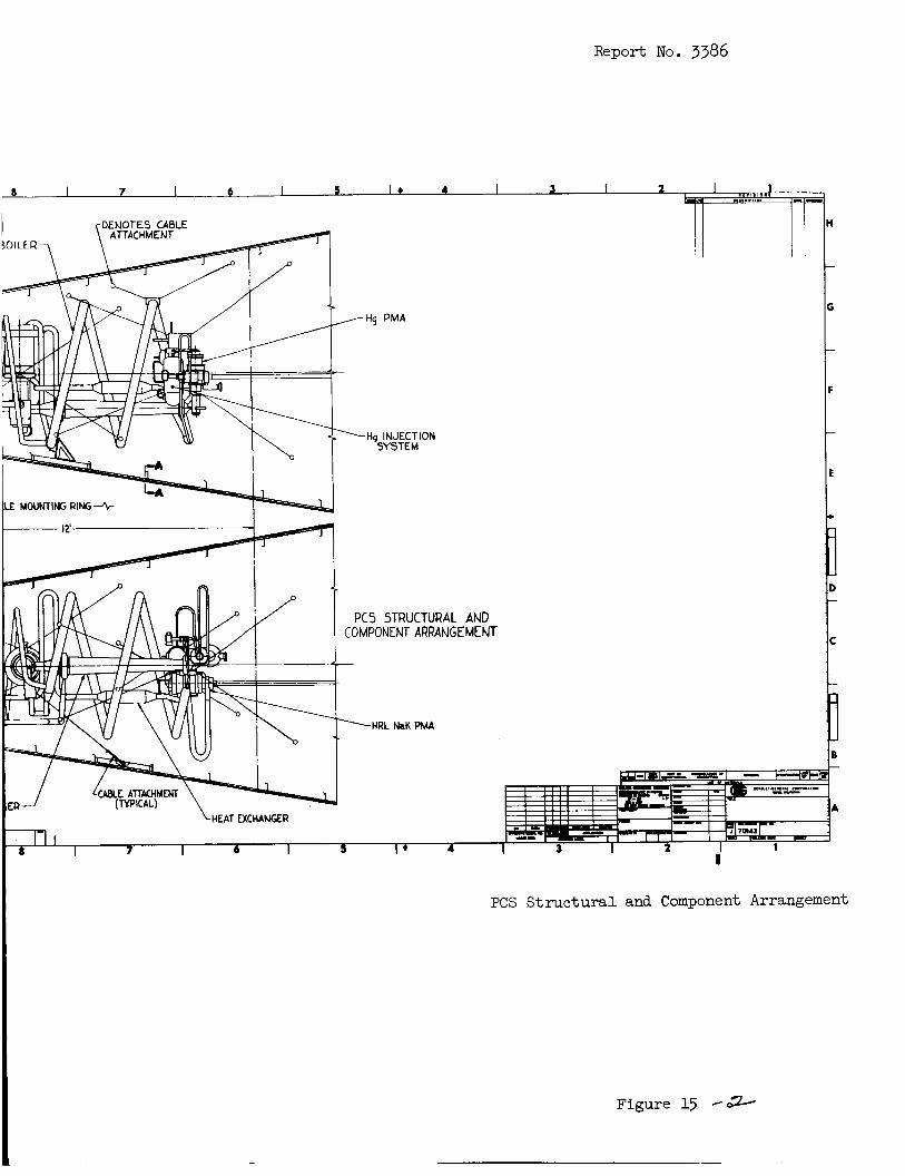
Report No. 3386
Hq INJECTION SYSTEM
PCS STRUCTURAL AND COMPONENT ARRANGEMENT
I PCS Structural and Component Arrangement
Figure 15 -*
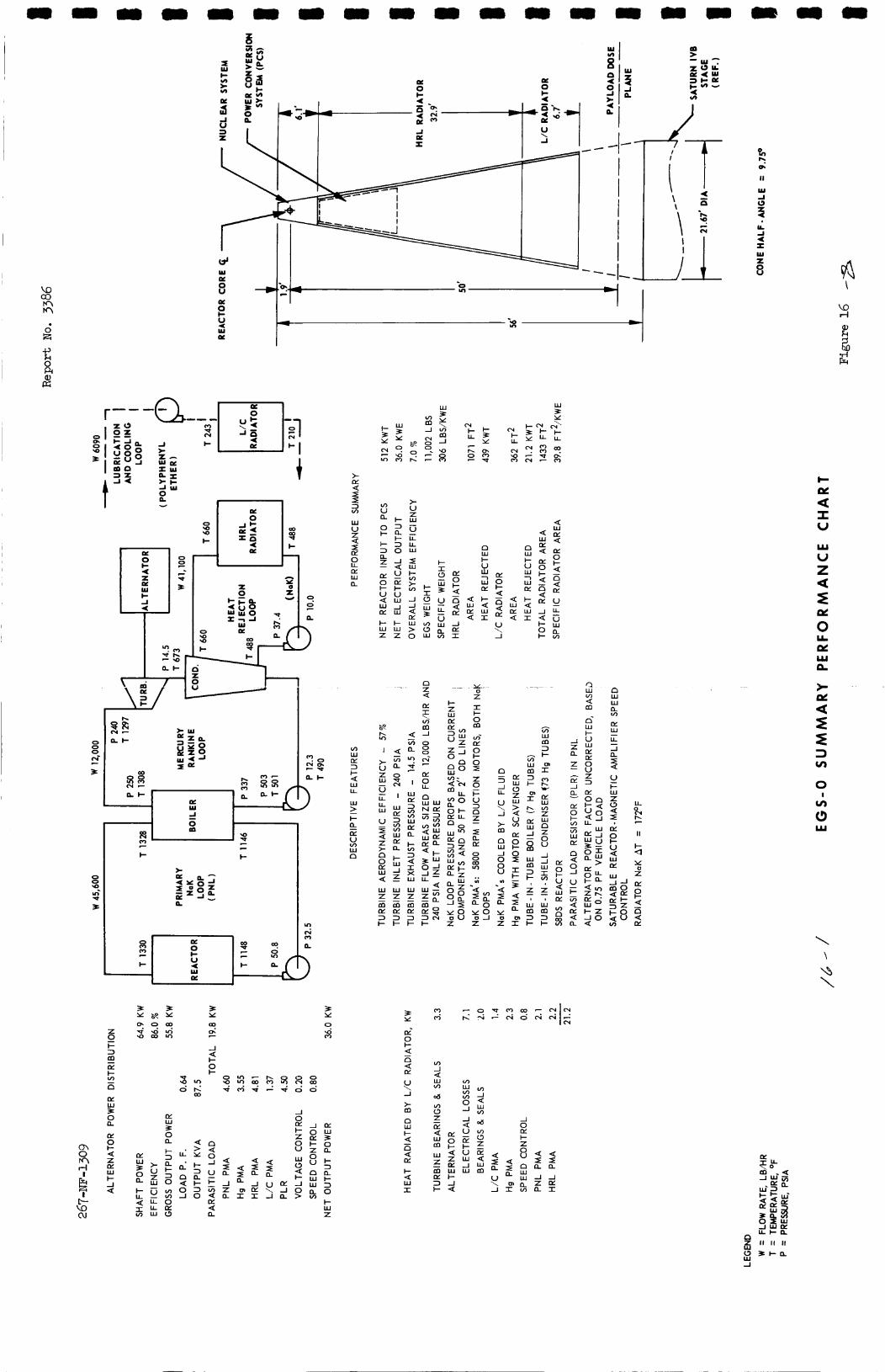
e
\
I ' ' I o?
2 4 I- I I W E
> lY Q I I >-
a 2 G u
0 I-
i- 3
Z a -
c &
I v a s
(IC 0
v)
I- 3 a I- 3 0
Q W lY Q
-1 Q
lY I- U W
u a
d lY Q
u
!%
U U w - -J
W
I- W Z
I- W Z
-1 lY I
U \ 1
i- 0 I-
- x n Q Z
- z
n - 3 -1 L L
U \ -I
> m n W 1 0 0 U VI
-4 I a Y
Z 0
U
W P
I- I-
*
x (1
n c
W (IC
3 Y
3 Y
9 3
3 3 P Y
z i- 3
lY
0
m
n z E W P 0 a
U \ -1
> m n W I- Q - n d I- Q w I
tn W tn
-I I;
v) -1 Q w tn
d
d
-1 4: U lY I- U W -1 W
-
-1 0 LK I- Z
8 s n a W W - J
% E
v) 0 f E 4 : : 2
lY 0 I- Q z e: W I- -1 a
ti a n Q (3
W Z
lY 3 I-
- m
Q
2 -J w I
a 2 -1 Z a
Q I a Q
I a m I
U \ -J
IY -1 a
m I
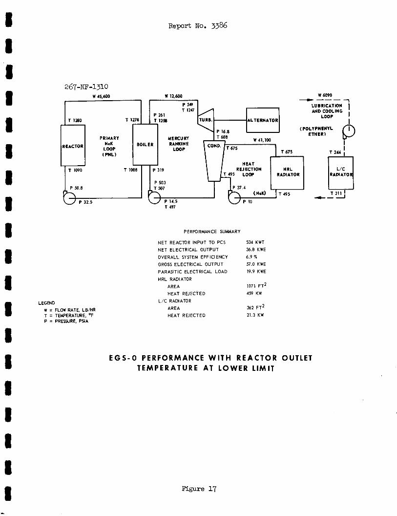
R e p o r t NO. 33%
2 67 -NF-1310 w 6090
1 P 249 LUBRICATION I
- --- W 45,600 w 12.600
AND COOLING LOOP I
T 1280 ALTERNATOR b ( POLYPHENYL ETHER)
PRIMARY NaK BOILER RANKINE
LOOP (PnL)
REACTOR
RAMATO T 1090 T 1088 P 319 REJECTION HRL
RADIATOR
P 503
+-I P 50.8
P 32.5 T 497
LEGEND W = FLOW RATE, LBMR T = TEMPERATURE, OF P = PRESSURE, PSlA
8
PERFORMANCE SUMMARY
NET REACTOR INPUT TO PCS
NET ELECTRICAL OUTPUT
OVERALL SYSTEM EFFICIENCY GROSS ELECTRICAL OUTPUT
PARASITIC ELECTRICAL LOAD
HRL RADIATOR AREA
HEAT REJECTED
L /C RADIATOR AREA
HEAT REJECTED
534 KWT 3 . 8 KWE
6.9 7%
57.0 KWE
19.9 KWE
1071 FT2
459 KW
362 F T ~
21.3 KW
EGS-0 PERFORMANCE WITH REACTOR OUTLET TEMPERATURE AT LOWER LIMIT
Figure 17
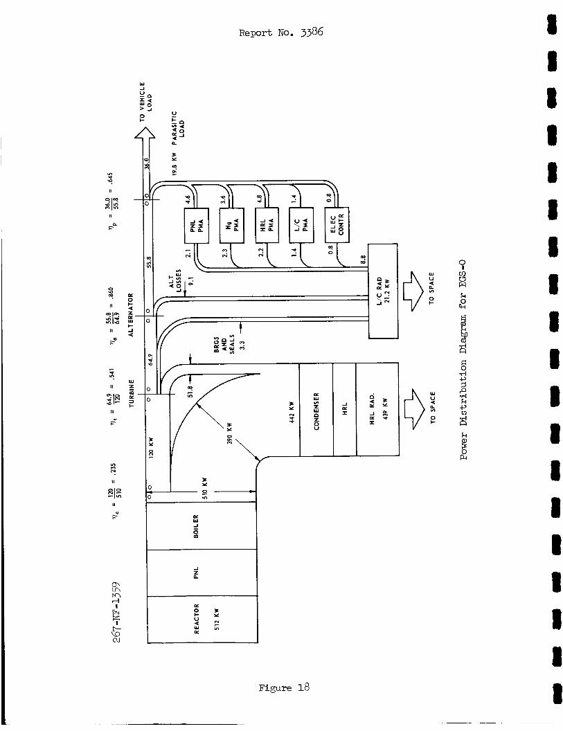
I A
c Figure 18
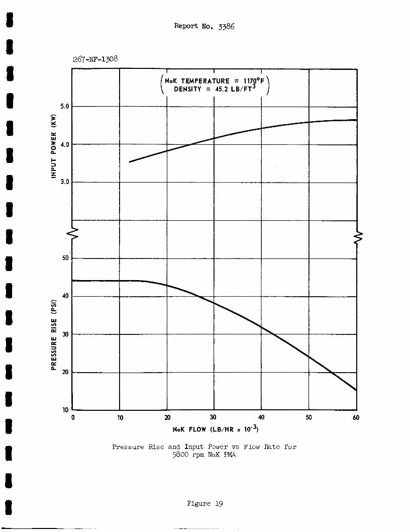
I 8 8 8 1 I I 1 8 8 I 8 8 I 1 8 t I 8
R e p o r t No. 3386
0 10 20 30 40 60
NaK FLOW (LB/HR x
Pressure Rise and Input Power vs Flow Fate f o r 5800 rpm NaK PMA
Figure 19
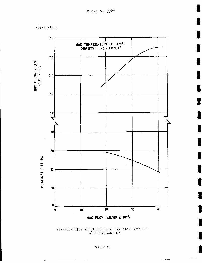
Report No. 3386
2.8 1 I I I
0 10 20 30 40
NaK FLOW (LB/HR x
Pressure Rise and Input Power vs Flow Rate f o r 4800 rpm NaK PMA
Figure 20
8 8 8 8 1 8 I 8 8 I 8 8 8 8 I 8 I I 8
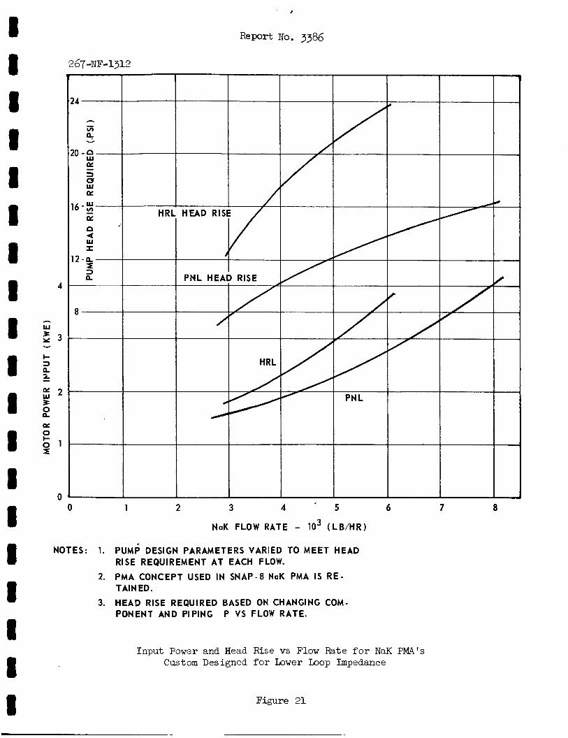
I 8 8 1 8 8 I I 8 8 8 8 8 8 8 8 8 8 8
24
h - v) 4 Y
20-fi 5 3 0 W E
16-z - a! P
I 12-IL I 3 a
2
8
r
Report No. 3386
HRL HEAD RISE
I
PNL HEAD RISE
HRL
267-NF-1312
0 1 2 3 4 - 5 6 7 8
NaK FLOW RATE - lo3 (LB /HR)
NOTES: 1 . PUMP DESIGN PARAMETERS VARIED TO MEET HEAD RISE REQUIREMENT AT EACH FLOW.
TAIN ED.
PONENT AND PIPING P VS FLOW RATE.
2. PMA CONCEPT USED I N SNAP-8 NaK PMA I S R E -
3. HEAD RISE REQUIRED BASED ON CHANGING COM-
Input Power and Head Rise vs Flow Rate f o r NaK PW's Custom Designed for b w e r Loop Impedance
Figure 21
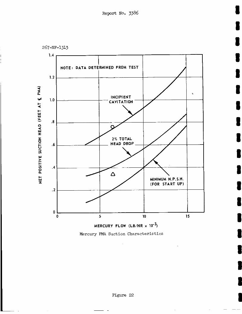
267-NF-1313
1.4
1.2
1 .o
.8
.6
.4
.2
0
I NOTE: DATA DETERMINED FROM TEST
INClPl ENT CAW TAT ION - -
2% TOTAL - HEAD DROP-
/
5 10
MINIMUM N.P.S.H. (FOR START UP)
1 15
MERCURY FLOW (LB/HR
Mercury PMA Suction Characteristics
Figure 22
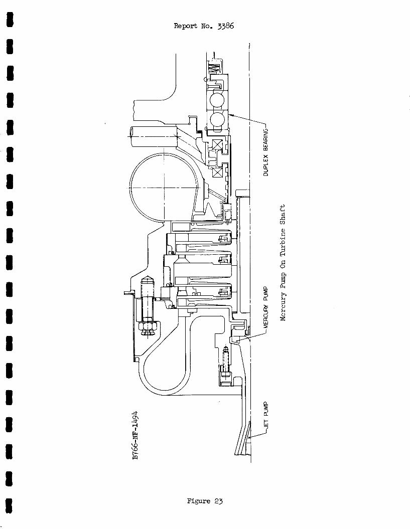
Report No. 3386
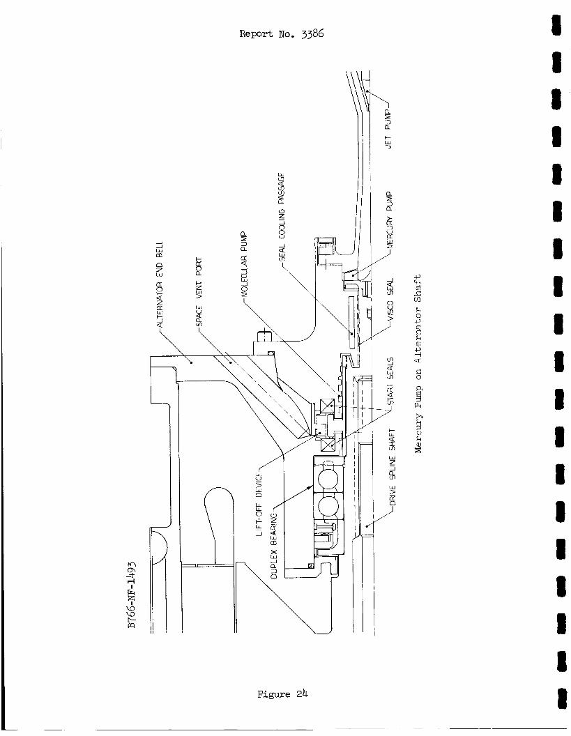
Figure 24
R e p o r t No. 3386
t- w -3
8 8 8 1 8 1 8 I 8 I I I 8 8 I 8 I 8 8
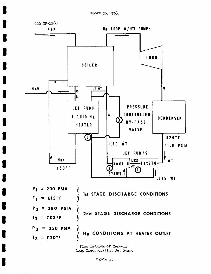
I 8 8 8 I I I 8 I 8 1 1 I I 8 8 8 8 8
666 -NF-U 80 N a K
Report No. 3386
H g LOOP W / J E T P U M P s
N a K I
JET P U M P
L I Q U I D H g
H E A T E R
I
I NaK
1 1 5 0 ° F
C
P R E S S U R E
O N T R O L L E D
B Y - P A S S
V A L V E
C O N D E N S E R
5 2 0 ° F 1 . 5 0 W T
JET P U M P S
l s t S T 6 1.225
2 n d S T 6
. 2 2 5 W T
1 1 . 0 P S l A
1 W T
1st STAGE DISCHARGE CONDITIONS
2nd STAGE DISCHARGE CONDITIONS
p i = 200 PSlA
11 = 615°F
P 2 = 3 8 0 P S l A
T2 = 703OF
P3 = 3 5 0 PSlA
T3 = 112OOF Hg CONDITIONS AT HEATER OUTLET
I 1 Flow Diagram of Mercury
Loop Incorporating Jet Pumps
Figure 25
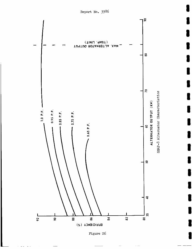
li ti v)
2
R e p o r t No. 3386
Figure 26
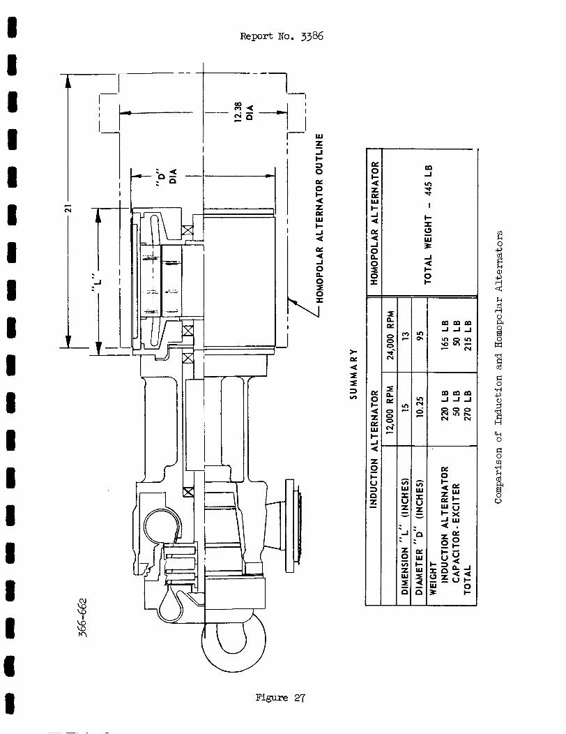
Report NO. 3386
I 1
1 I I
I
t 1 1
cu v3 v3 I
M 8
I
W
-I I- 3 0 o?
4 Z o? W I- J 4 o? 4 J 0 n 0 =E 0 I
5
2
I I
- I
Figure 27
>. o? 4 I I 3 v)
- ni 0 c 4 Z o? W I-
4 o?
J
0 x 0 I
a
E!
- -
o? 0 I- 4 Z o? W I- J 4
Z
I- U 3
0
n f
m m m J J J
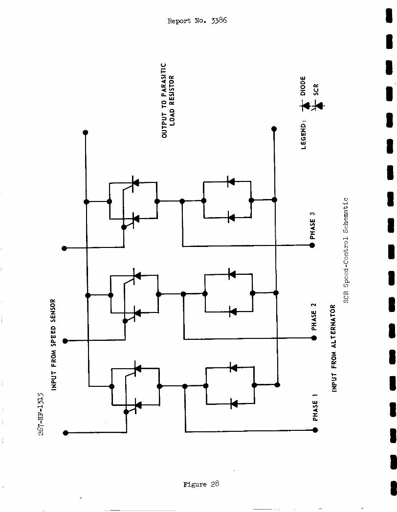
oc
Z w v)
W w L v)
I
s n
2 LL
R e p o r t NO. 3386
.. n Z W 0 w A
I e
Figure 28
*
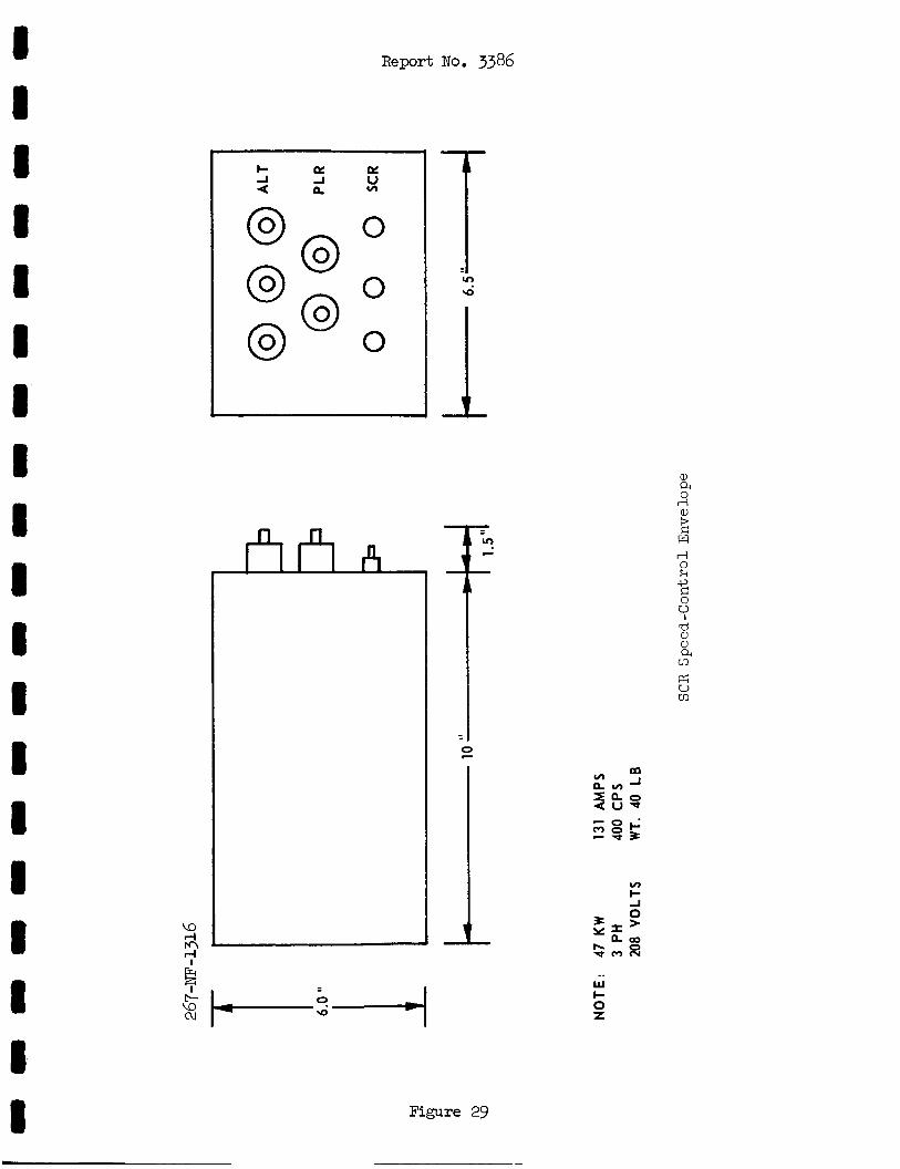
Report No. 3386
0
0
0
d
Figure 29
Q) Q 4
ffi V cn
.. W c 0 Z
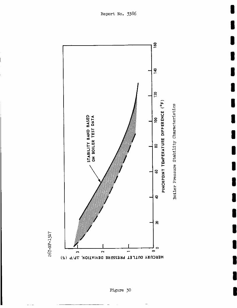
R e p o r t No. 3386
0 0
h
LL 0
W U I W er W L L
v
- n W e 3 I- 4 e W n
F b
0
I U
L
5
z n
f
Figure 30
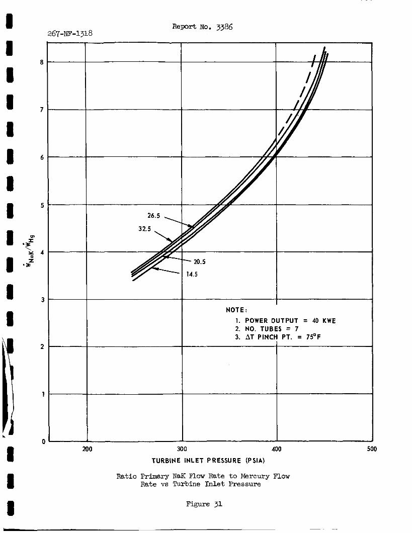
Report No. 3386 267-NE-1318
NOTE:
1. POWER OUTPUT = 40 KWE 2. NO. TUBES = 7 3. AT PIN( PT. = 75OF
200 300 400 TURBINE INLET PRESSURE (PSIA)
Ratio Primary NaK Flow Rate to Mercury Flow Rate vs Turbine Inlet Pressure
Figure 31
500
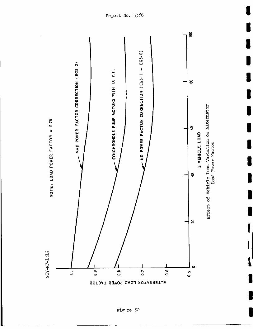
K W
.. W I- 0 Z
h
cv m c3 W
Z
F U W K K 0 V K 0 I- V 4 U
K W 3
Y
0
2 x 4 z
R e p o r t No. 3386
c 0
v)
(3 W
I - In (3 W
Z
I- V W K K 0 V K 0 I- V
U
K W 3 0 [L
2
a
Figure 32
t-l 0 -P 0
k w 8
0 cy
0
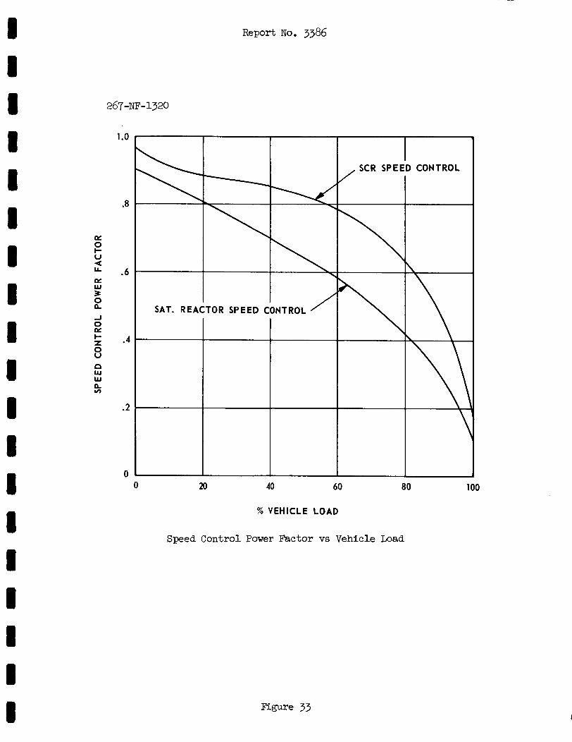
Report No. 3386
0 0 20 40 60 80 100
% VEHICLE LOAD
Speed Control Power Factor vs Vehicle Load
1 .o
.8
K 0 I- U 4
K W 3
.6
B 0 K
0 U
5 .4
n W W LL v)
.2
Figure 33
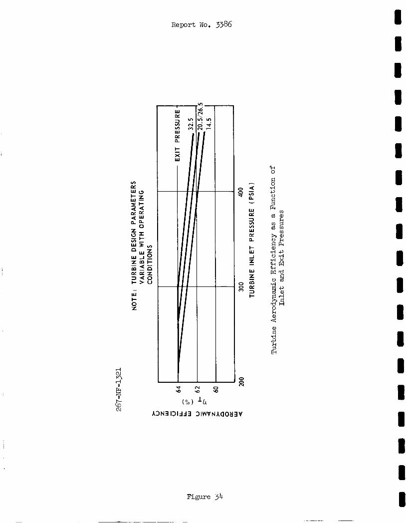
Report No. 3386
Figure 34
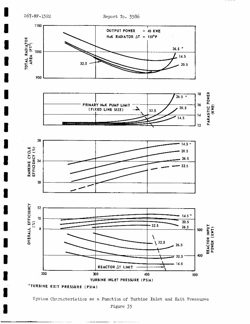
I I I I I I I I I I 1 1 I 1 I I 8
1100
K 0 I-- $I-
2 !5 1000
A K
3 % 0 I-
900
I I
- I OUTPUT POWER = 40 KWE
NaK RADIATOR AT = 15OoF
26.5 * 14.5
20.5
267-NF-1322 Report No. 3386
i a
16
14
12
28
20
>- U
W z l2 - ; 10 L L - use
v
500 ~a J 4 K W > 0
400
200 300 400 500 TURBINE INLET PRESSURE (PSIA)
*TURBINE E X I T P R E S S U R E ( P S I A )
System Charac te r i s t ics as a Function of Turbine I n l e t and Exit Pressures
Figure 35
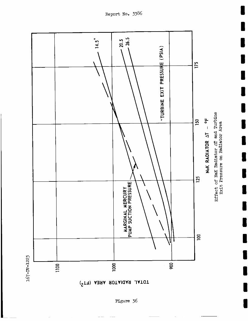
c v! Q v
Figure 36
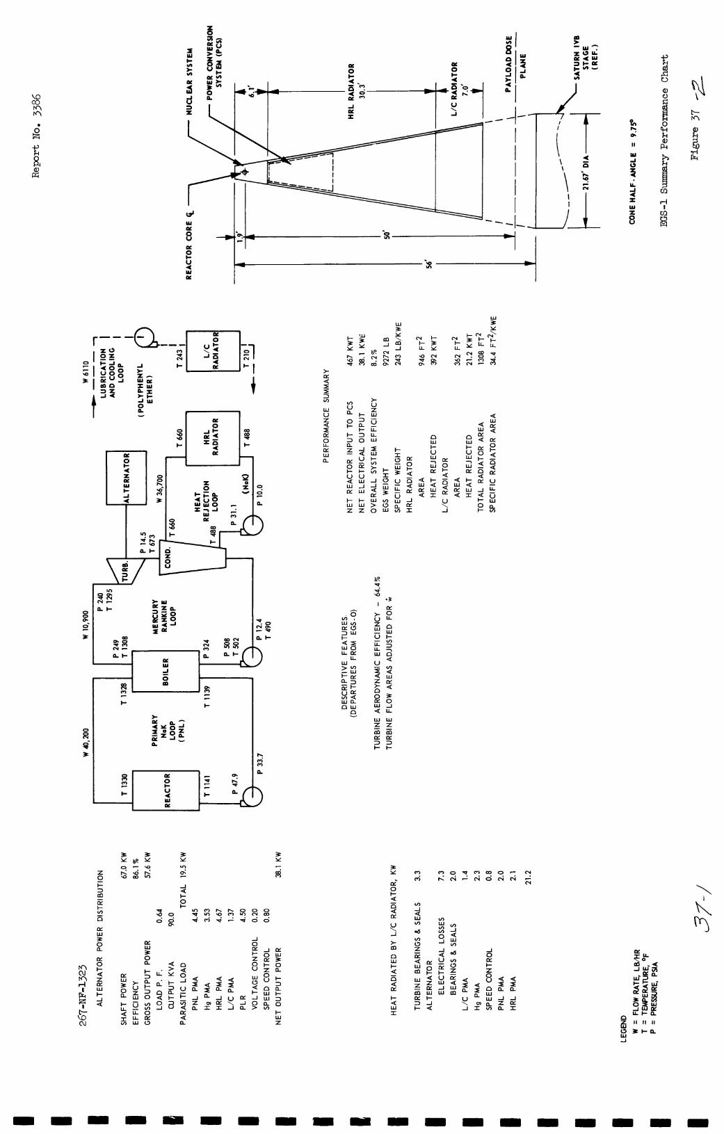
z A a
/-
U \ +---I A I I e,
h 0.
II
W
$ Y A 4 I Y Z
8
F Y
I ui m
L = - " a 2 t-u 3 u o w n
W C Y
W I- U
z g Lz:
n W I- z: a 7 W Lz: I- < W I L
I- W Z
U \ -1
I-
%
h
n m (3
E d -
V \ -1
* m n W
v) 0 Z CY - 5 m
m
W Z
CY 3 I-
-
2.a
4: 2 -1 Z a
< 2 -1 Lz: I
w w m I- -1 4:
I- < W I
U \ -I
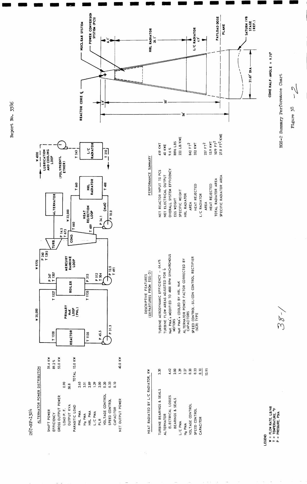
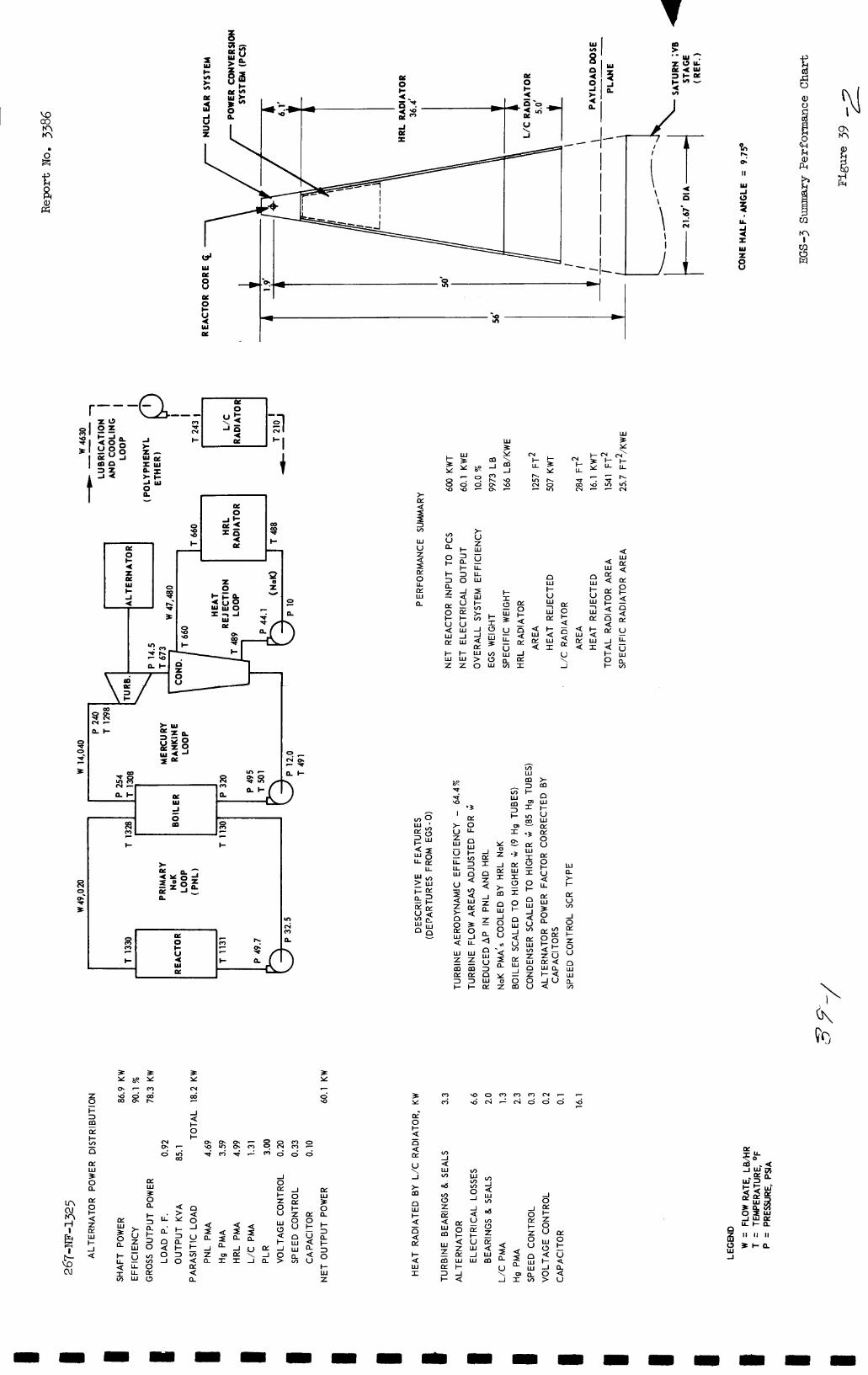
I i E I
4 -3 I w =
r-- W 5
2 E 2
ILa
a I -
I- I - 3 3 0 a
c r u o w I-I- u u Q W W J I Y W
> U Z W - u LL U W n
W I- z 7 W CY
I- Q W r
n W I- z 7 W lx I- Q W I
E 0 I- Q
Q rY
- n J J 6 IY w > 0
2 Q
I-I- W W z z
J LY I
c;' \. Jl
I I - J rY I
Z Q -I Z
n
a z a a
E
U Q LL
e w * I-
CY
a
2 .J 0 CY c Z 0 u n
n
W U 3
W D!
n
a W ilLl
VY
3 Y
0 7
Y) * Y
d 0
J Q I- O
CY U \ -I
> m LLI W 3 0 a
J
I- Z 0 U
g J
I- Z 0 U
52 n W I- Q 6 d
Q > Y
J 4
& I- U W -I W
u J 0 E I- z 0 U
8 Z PL Q W m
- W 0 Q I- J 0 >
Q
2 J PL I
Q I a .U \ J
I- 3
I- 3 0
a
W 3 0 a
Q I a m I
- U
Q U
2 n
% W W Q
I a I-
Q W I
n
% W W
J a
U \ -I
Q a
m I
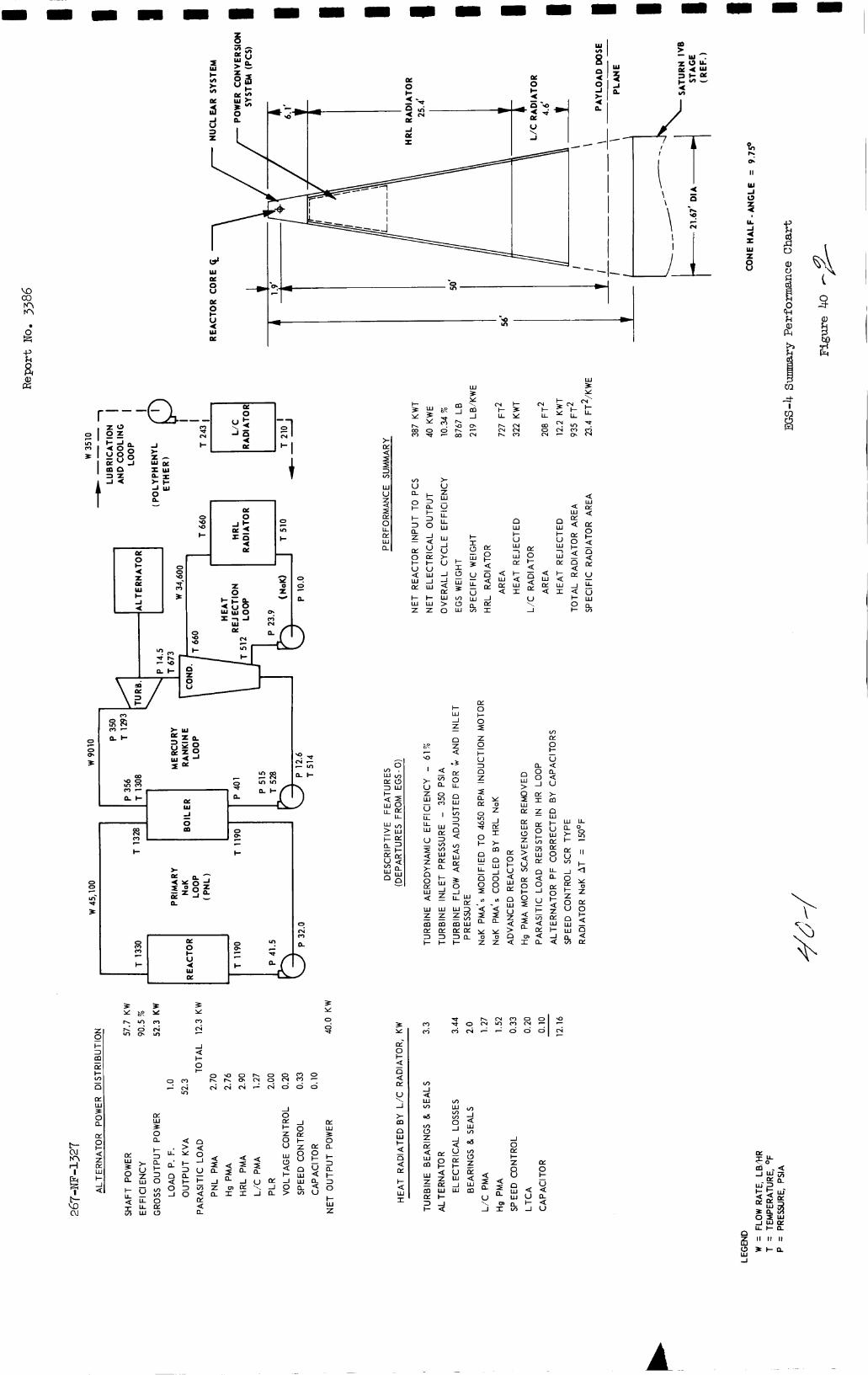
3 Y
3 s 3 Y
8 'p
E I - 0 W I - J O z r
d v)
a5 In c7
w $ Z E m w E t - 3 1 t - Q :
a5
m n
e=J
W W
J
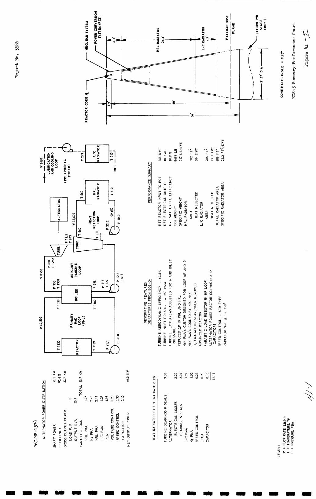
I 0 I- U < W I
x z - m n t
3 Y
x v
A a
ou, h 0.
II
w A 0 f u. A < I W Z 0 U
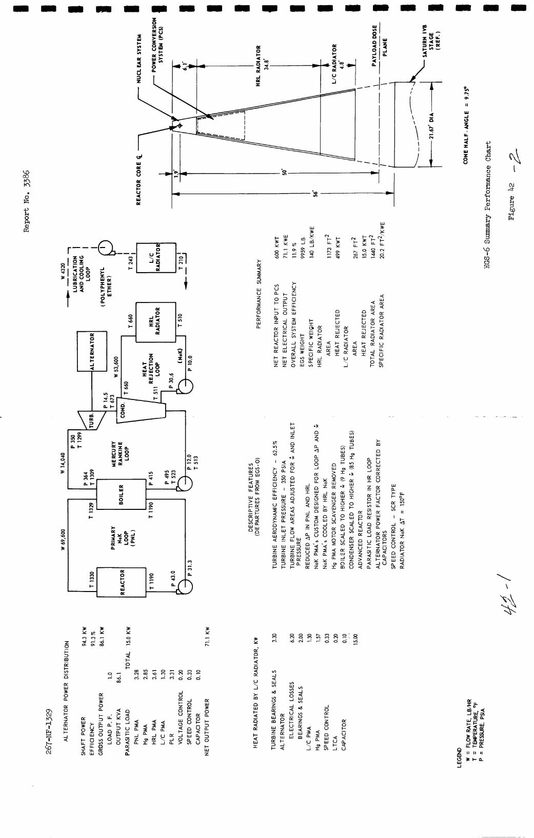
?n h 01
I I
w A s
\ \ -2 ' I I
Y A 4 x W
8 d W w 8 - u3 co
M M
w a W 3 Y
r--
w V Z Q I LY 0 U LY w a
2: I - 3 3 0 n z - 1 - Q LYU o w I-I- v u Q w w - 1 L Y w
+ I - w w z z
- u U LL W
4: w a: Q
-I -1 Q LY W > 0
-1 LY r
V \ -1
.z I- w
I-
Z 0 - t
V \ -1
2 n W
LY W
a: W 3 0 a
a: W P 2
-1 0 LY I- Z 0 u
I- d I-
; 3 0
a 5 a V \ -1
-1
u L
Q I Q a 5
Y E -11
n
a
W W
v,
-1 Z a
J a: I
w -1 a
I- Q W I
a < V E
LL LL W
I- LL Q 5
I- W z
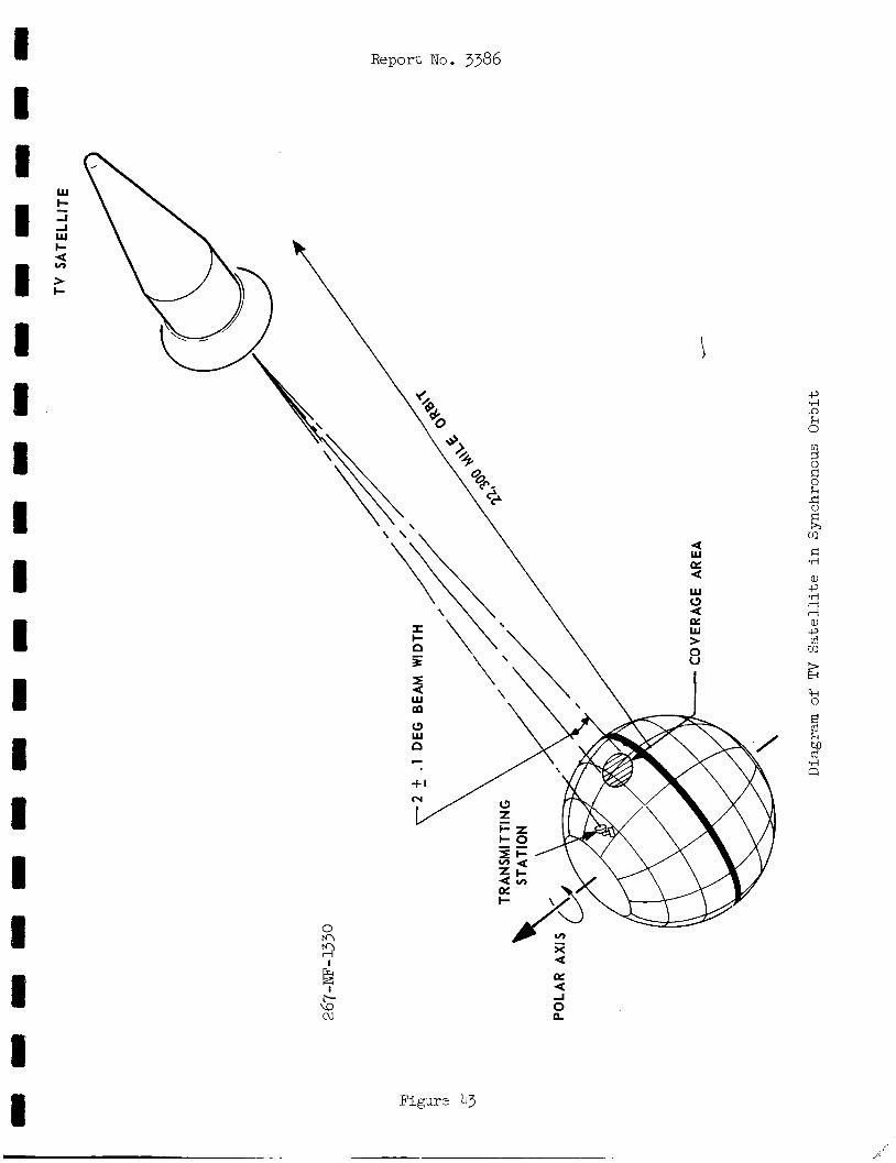
W c -I
w c 4
> c
-
v)
Report No. 3386
t 1.
Figure 43
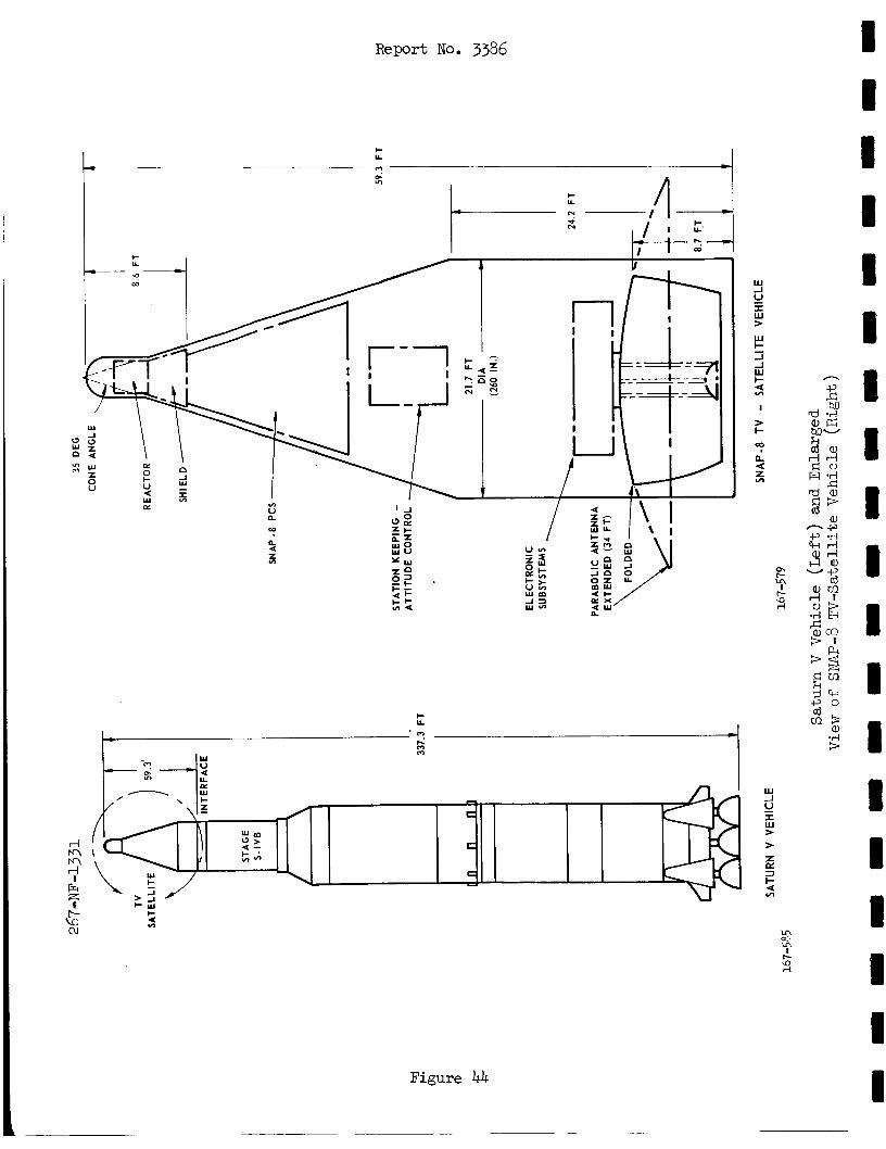
Report No. 3386
Figure 44
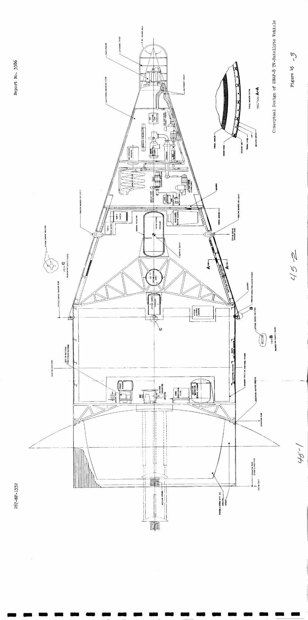
? 2! R cn k 0
c w z Q c U Lu m
-d m n, u
I-t \ .. Y /
\ \ I '
+-t-
\
I ._ j
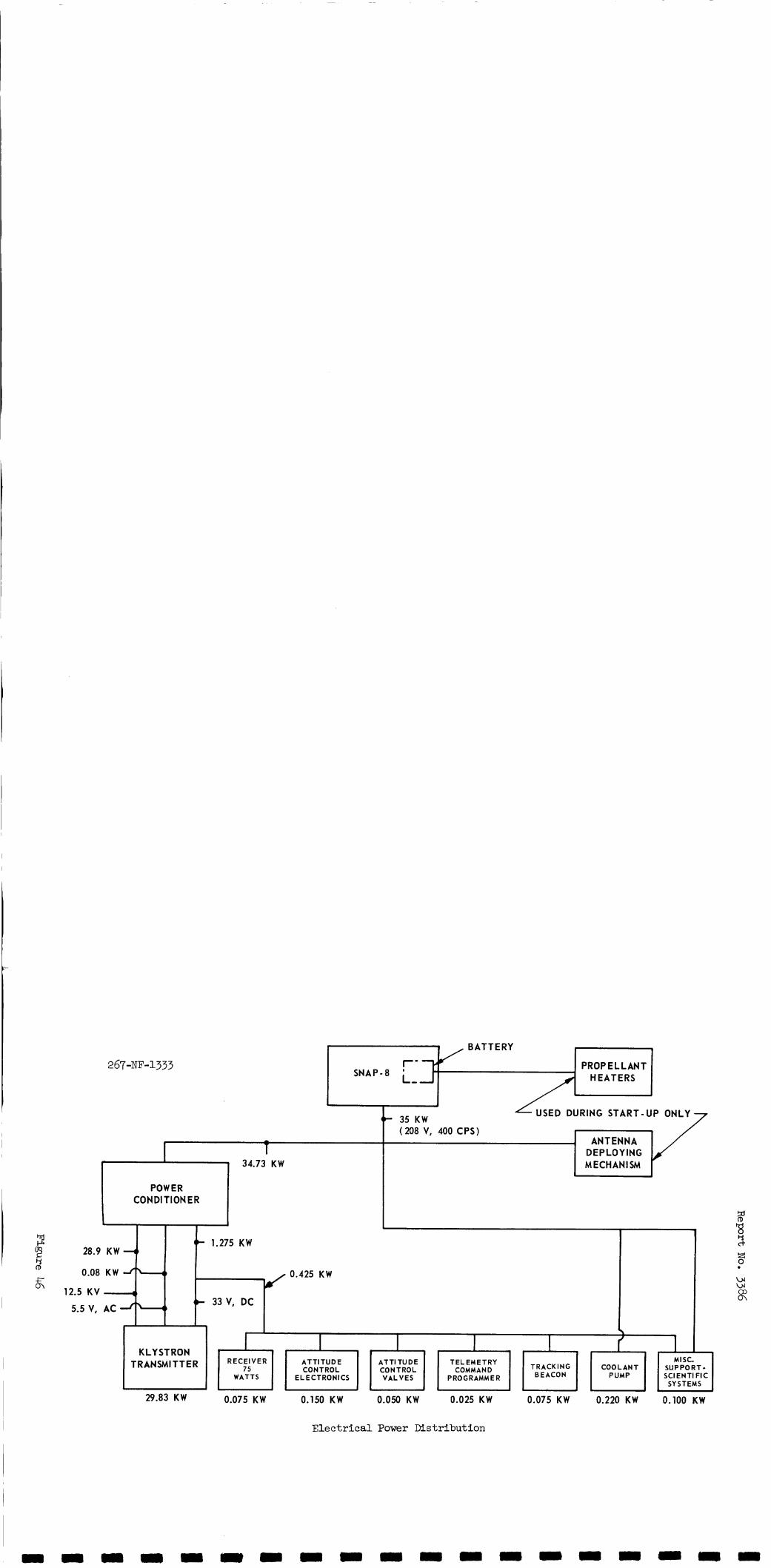
12.
5
r- PROPELLANT L, HEATERS SNAP-8
28.9
0.08
5 K V
'-5 v,
I - 1 r 1 34.73 KW
(k 35 KW ( 208 V, 400 CPS)
ANTENNA DEPLOYING M ECH AN I SM
K W 4 1
KW
( 1
AC
POWER CONDl TI ON E R
(+ 1.275 KW
IF 33 V, DC J k l
0.425 KW
MISC. SUPPORT- SCIENTIFIC
SYSTEMS
KLYSTRON T RANSMI T T E R COOL ANT TRACKING RECEIVER A T T l TUD E A T T l TU DE T EL EM ETRY
BEACON PUMP 75 CONTROL CONTROL COMMAND
WATTS ELECTRONICS VALVES PROGRAMMER
29.83 KW 0.075 KW 0.150 KW 0.050 KW 0.025 KW
Electrical Power Distribution
0.075 KW 0.220 KW 0.100 KW
d Y
ct-
3 w w co rn
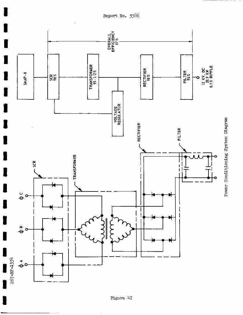
Report No. 3386
u e
I I
I I I I
Figure 47
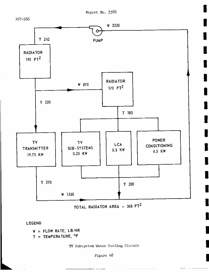
Report No. 3386
LCA 0.3 KW
167-586
L
POWER CONDITIONING
4.5 KW
w 2220
I T 242 PUMP
TV TRANSMITTER
19.75 KW
T 270
1
TV SUB -SYSTEMS
0.25 KW
W 1350
TOTAL RADIATOR AREA - 368 FT2
LEGEND
W = FLOW RATE, LB/HR T = TEMPERATURE, OF
TV Subsystem Water Cooling Circu i t
Figure 48
1 8 I 1 I I
I 1 1 I I 1 I 1 I 1 1 I
m
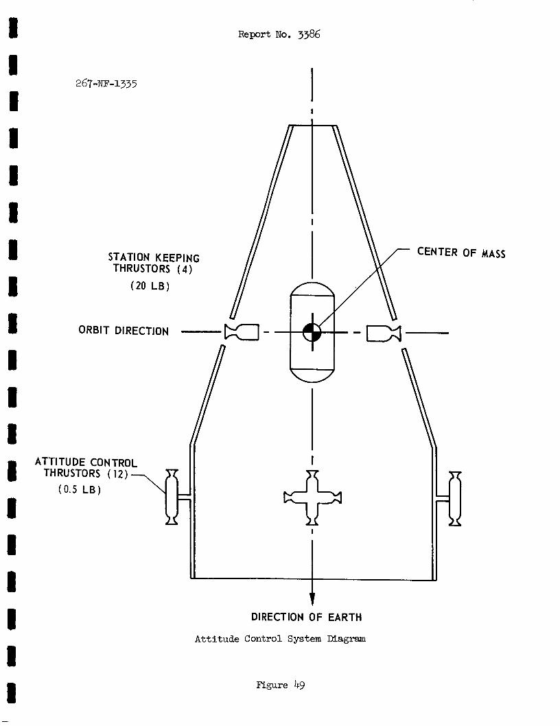
i I I
Report No. 3386
I
MASS
DIRECTION OF EARTH
Attitude Control System Diagram
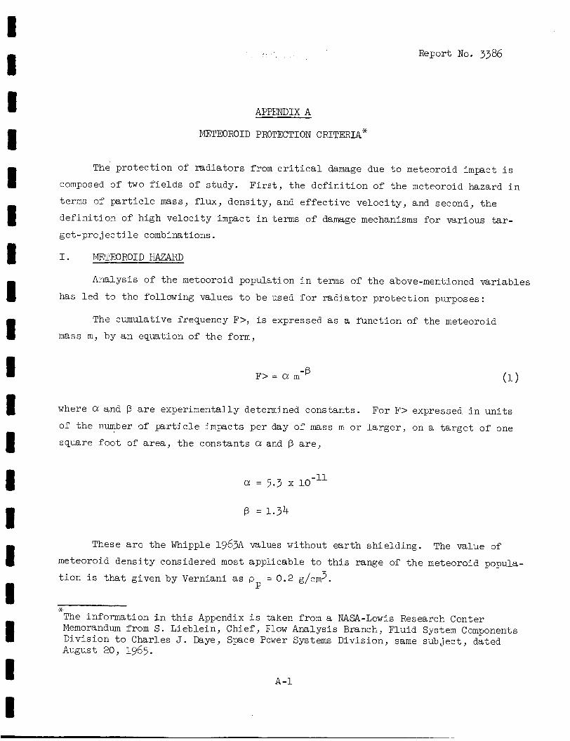
Report No. 3386
APPENDIX A
METEOROID PROTECTION CRITERIA*
The' p ro t ec t ion of r a d i a t o r s from c r i t i c a l damage due t o meteoroid impact i s
composed of two f i e l d s of study.
terms of p a r t i c l e mass, f lux, dens i ty , and e f f e c t i v e ve loc i ty , and second, t h e
d e f i n i t i o n of high v e l o c i t y impact i n terms of damage mechanisms f o r various tar- get-prc j ec t i l e combinations.
F i r s t , t h e d e f i n i t i o n of t h e meteoroid hazard i n
I . METEOROID HAZARD
Analysis of t h e meteoroid population i n terms of t h e above-mentioned va r i ab le s
has l e d t o t h e following values t o be used f o r r a d i a t o r p ro tec t ion purposes:
The cumulative frequency F>, i s expressed as a func t ion of t he meteoroid
mass m, by a n equation of t h e form,
-B F > = a m
where a and B a r e experimentally determined constants . For F> expressed i n u n i t s
of t h e number of p r t i c l e impacts pe r day of mass m or l a r g e r , on a t a r g e t of one
square f o o t of a r e a , t h e constants a and B are,
-11 a = 5.3 x 10
These a r e t h e Whipple 1963A values without e a r t h sh i e ld ing . The value of meteoroid d e n s i t y considered most appl icable t o t h i s range of t h e meteoroid popula-
t i o n i s t h a t given by Verniani as p = 0.2 g/cm3. P
* The information i n t h i s Appendix i s taken from a NASA-Lewis Research Center Memorandum from S. Lieblein, Chief, Flow Analysis Branch, Fluid System Components Divis ion t o Charles J . &ye, Space Power Systems Division, same sub jec t , dated August 20, 1965.
A - 1
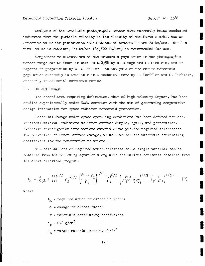
Meteoroid Protect ion Cri ter ia (cont . ) Report No. 3386
Analysis of t h e a v a i l a b l e photographic meteor da t a c u r r e n t l y being conducted
ind ica t e s t h a t the p a r t i c l e ve loc i ty i n t h e v i c i n i t y of the E a r t h ' s o r b i t has a n
e f f e c t i v e value for penetrat ion ca l cu la t ions of between 17 and 20 km/sec.
f i n a l value i s obtained, 20 km/sec (65,500 f t / s e c ) i s recommended f o r use.
U n t i l a
1 I 8 D I I I 1 I
Comprehensive discussions of t h e meteoroid population i n t h e photographic
meteor range can be found i n NASA TN D-2958 by N. Clough and S. L ieb le in , and i n
r e p o r t s i n preparation by C . D. Miller. An a n a l y s i s of t he e n t i r e meteoroid
population cu r ren t ly i s a v a i l a b l e i n a t echn ica l note by I. Loeff ler and S. L ieb le in ,
c u r r e n t l y i n e d i t o r i a l committee review.
11. IMPACT DAMAGE
The second area r equ i r ing d e f i n i t i o n , t h a t of high-veloci ty impact, has been
s tudied experimentally under NASA con t r ac t w i t h t h e a i m of generat ing comparative
design information for space r a d i a t o r meteoroid p ro tec t ion .
P o t e n t i a l damage under space operating conditions has been defined for con-
vent ional material r a d i a t o r s as inner su r face dimple, spall, and pe r fo ra t ion .
Extensive inves t iga t ion i n t o various materials has yielded required thicknesses
f o r prevention of inner surface damage, as w e l l as f o r t h e ma te r i a l s c o r r e l a t i n g
c o e f f i c i e n t f o r the pene t r a t ion r e l a t i o n s .
The ca l cu la t ions of required armor thickness for a s i n g l e material can b e
obtained from the following equation along wi th t h e var ious constants obtained from
the above described program.
u 3 62.4 1/2 2/3 1/38 1/38 8 1
a t = a Y (:) pp ( P t (F) (*) (*] ( 2 )
where
- ta -
a =
Y = - -
pP
P t - -
required armor thickness i n inches
damage thickness f a c t o r
ma te r i a l s c o r r e l a t i n g c o e f f i c i e n t
0.2 g/cm3
t a r g e t ma te r i a l d e n s i t y l b / f t 3
A-2
1 1 1 I I
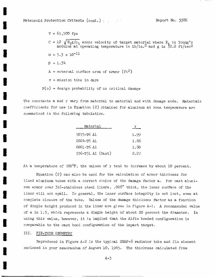
Meteoroid Pro tec t ion Criteria (cont . )
v = 65,500 f p s
Report No. 3386
C = 12 dEtg/pt sonic ve loc i ty of t a r g e t ma te r i a l where E i s Young‘s modulus a t operating temperature i n lb / in .2 and g is 52.2 f t / s e c 2
a = 5.3 x 10⁻¹¹
@ = 1.34
A = ex te rna l surface area of armor ( f t 2 )
T = mission time i n days
P ( o ) = design p robab i l i t y of no c r i t i c a l damage
The constants a and y vary from material t o material and with damage mode. Materials
c o e f f i c i e n t s f o r use i n Equation ( 2 ) obtained f o r aluminum a t room temperature are
summarized i n t h e following tabula t ion .
Material Y 7075-T6 A 1 1.99 2024-T6 A 1 1.86 6061-~6 A 1 1.80 356-T51 A 1 (Cast) 2.27
A t a temperature of TOO-, t h e values of y tend t o increase by about 10 percent .
Equation ( 2 ) can a l s o be used f o r t h e c a l c u l a t i o n of armor thickness f o r
l i n e d aluminum tubes wi th a co r rec t choice of t h e damage f a c t o r a . For c a s t alumi-
num armor over 316-stainless s t e e l l i n e r s , .028” t h i c k , t h e inner su r face of t h e
l i n e r w i l l not s p l l . I n general , the i n n e r su r face i n t e g r i t y i s not l o s t , even a t complete c losu re of the tube. Values of t h e damage thickness f a c t o r as a func t ion
of dimple he igh t produced i n t h e l i n e r a r e given i n Figure A-1. A recommended value
of a is 1 .5 , which represents a dimple he igh t of about 20 percent t h e diameter. I n
using t h i s value, however, i t i s implied t h a t t h e A l f i n bonded configurat ion i s
comparable t o t h e c a s t bond configuration of t h e impact t a r g e t .
111. FIN-TUBE GEOMETRY
Reproduced i n Figure A-2 i s t h e t y p i c a l SNAP-8 r a d i a t o r tube and f i n element
enclosed i n your memorandum of August 10, 1965. The thickness ca l cu la t ed from
A-3
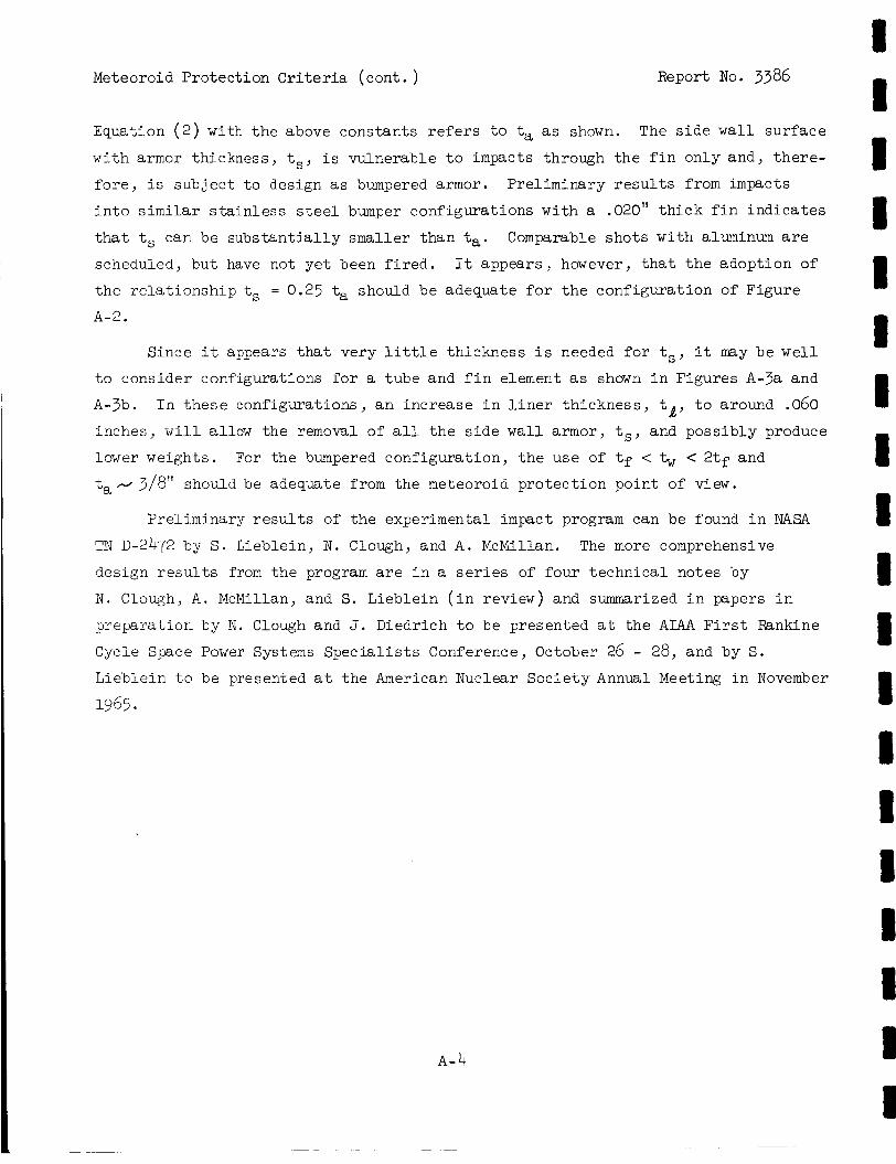
Meteoroid Protect ion Criteria (cont . ) Report No. 3386
Equation ( 2 ) w i t h t h e above constants r e f e r s t o ta as shown. The s i d e w a l l su r f ace
wi th armor thickness, ts, i s vulnerable t o impacts through t h e f i n only and, t he re -
f o r e , i s sub jec t t o design as bumpered armor. Preliminary r e s u l t s from impacts
i n t o similar s t a i n l e s s s t e e l bumper configurat ions wi th a .020" t h i c k f i n i n d i c a t e s
t h a t ts can be s u b s t a n t i a l l y smaller than ta.
scheduled, b u t have not ye t been f i r e d . It appears , however, t h a t t h e adopt ion of
t h e r e l a t i o n s h i p ts = 0.25 ta should be adequate f o r t h e configurat ion of Figure
Comparable sho t s wi th aluminum are
A-2.
Since it appears t h a t very l i t t l e thickness i s needed f o r ts, it may be w e l l
t o consider configurations f o r a tube and f i n element as shown i n Figures A-3a and
A-3b. I n t h e s e configurations, a n increase i n l i n e r thickness , tQ, t o around .060
inches, w i l l a l l o w t h e removal of a l l t h e s i d e w a l l armor, ts, and poss ib ly produce
lower weights. For t he bumpered configurat ion, t h e use of tf < < 2tf and
ta + 3/8" should be adequate from the meteoroid p ro tec t ion point of view.
Preliminary r e s u l t s of t h e experimental impact program can be found i n NASA
TN D-2472 by S. Lieblein, N. Clough, and A. McMillan.
design r e s u l t s from the program are i n a series of four t echn ica l notes by
N . Clough, A . McMillan, and S. Lieblein ( i n review) and summarized i n papers i n
preparat ion by N . Clough and J. Diedrich t o be presented a t t h e AIAA F i r s t Rankine
Cycle Space Power Systems S p e c i a l i s t s Conference, October 26 - 28, and by S.
Lieblein t o be presented a t the American Nuclear Socie ty Annual Meeting i n November
The more comprehensive
1965
A- 4
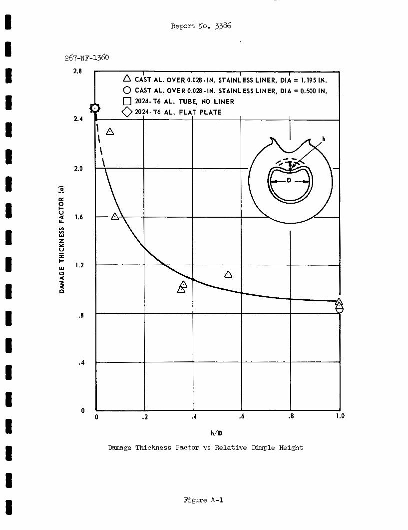
Report No. 3386
267-NF-1360
2.8
2.4
2.0
1.4
1.2
.8
.4
0
c
CiST AL. OVER Ok28-IN. STAINI!ESS LINER, DI; = 1.195 IN.
f
0 .2 .4 .4 .8 1 .o
h/D
Camage Thickness Factor vs Relative Dimple Height
Figure A - l
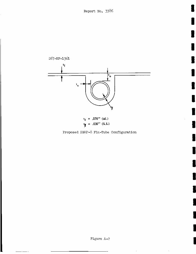
Report No. 33%
. ‘f 1
tf = .070” (AI.)
tf = .030” (S.S.)
Proposed SNAP-8 Fin-Tube
k
Configuration
Figure A-2
Report NO. 33%
A. INTEGRAL ARMOR
‘f
t
B. BUMPER PRINCIPLE
Alterna t ive Fin-Tube Configurations
Figure A-3
Report No. 3386
APPENDIX B
ELECTRICAL GENERATING SYSTEM WEIGHTS
The t a l e s i n t h i s appendix present t h e weights of each EGS s-udied i n the
performance p o t e n t i a l program.
n i f icance of t h e values l i s t e d . The weights f o r t h e PCS a r e grouped by loops as
Primary N a K loop, mercury loop, e t c . Dry weights, l i q u i d inven to r i e s i n com-
ponents, and wet weights a r e l i s t e d .
l i s t e d sepa ra t e ly a t the bottom of the d e t a i l e d system weight breakdown.
Remarks a r e given t o a i d i n i n t e r p r e t i n g t h e s i g -
The t o t a l f l u i d inventory of each loop i s
The e f f e c t of system improvement and s p e c i f i c component s u b s t i t u t i o n or i m -
provement on o v e r a l l system weight can be determined by comparing the weight break-
down for t he two systems involved i n t h e change.
t o be compared d i r e c t l y s ince they have a comparable n e t power output.
-6 both have a r e a c t o r input of 600 kwt; these systems a r e d i r e c t l y comparable.
EGS-0, -1, -2, -4,, and -5 a r e
ES-3 and
B -1
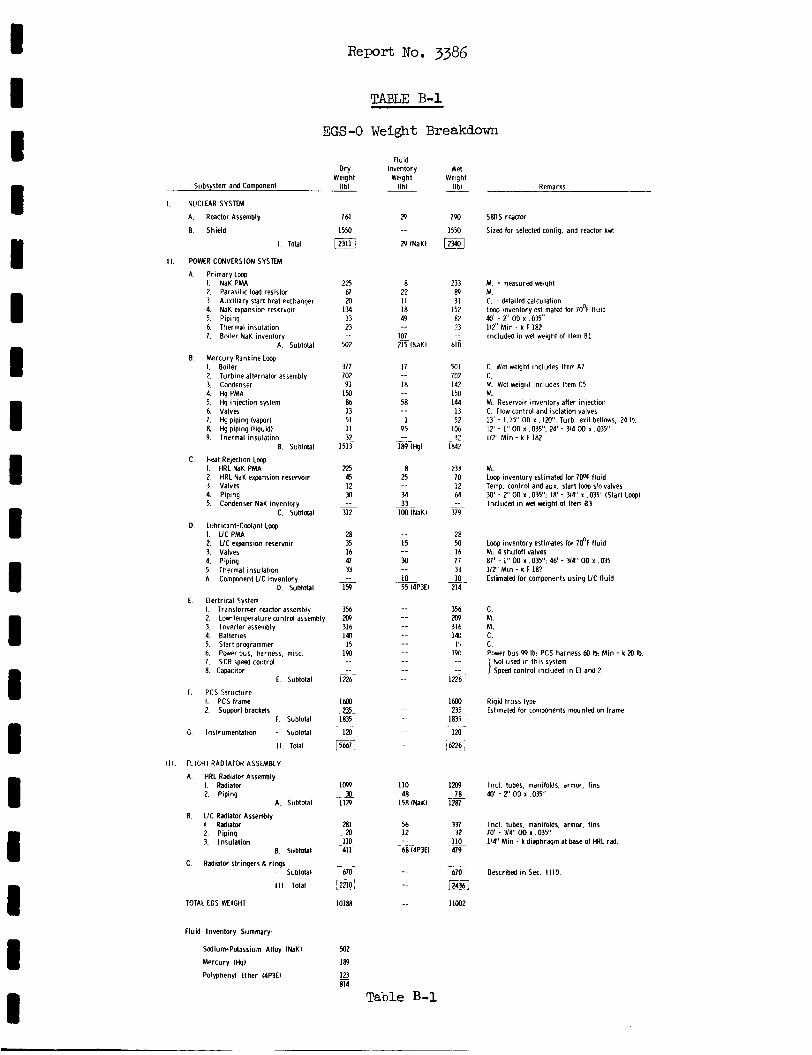
R e p o r t No. 3386
D 1 1 I D I I D D I D 8 I I I I I D
EGS -0
Dry Weight
Subsystem and Component l lb l
I. NUCLEAR S Y S W
A Reactor Assembly
E. Shield
1. Total
11. POWER CONVERSION SYSTEM
A Primary Loop I. NaK PMA 2. Parasitic load resistor 3 Auxiliary start heat exchanger 4. NaK expansion reservoir 5 Piping 6 Thermal insulation 7 Boiler NaK inventory
A. Subtotal
B. Mercury Rankine Loap I. Boiler 2. Turbine alternator assembly 3. Condenser 4. Hg PMA 5. Hg iniection syrtem 6 Va lvs 7. Hg piping lvaporl 8. Hg piping I l iquidl 9. Thermal insulation
B. Subtotal
C. Heat Rejection Loop I. HRLNaK PMA 2. HRL NaK expansion reservoir 3 Valves 4. Piping 5. Condenser NaK inventory
C. Subtdal
D. Lubricant-Coolant Lmp I. UCPMA 2. UC expansion reservoir 3. Valves 4. Piping 5 Thermal insulation 6. Component UC inventory
D. Subtotal
I. Transformer reactor assembly 2. Low-temperature control assembly 3. Inverter assembly 4. Batleries 5. Start programmer 6 Power bus. harness, misc. 7 SCR speed contrd 8. Capacitor
E. Electrical System
E Subtotal
F. PCS Structure I. PCS frame 2. Support brackets
F. Subtotal
C Instrumentation - Subtotal
II Total
Ill. FLIGHTRADIATOR ASSEMBLY
I. Radiator 2. Piping
A. HRL Radiator Assembly
A. Subtdal
B. UC Radialor Assembly I. Radiatw 2 Piping 3. Insulation
E. Subtotal
- Subtotal C Radiator stringers& rings
Ill. Total
TOTAL ECS WEIGHT
Fluld Inventory Summary:
Sodium-Pdassium Alloy INaKI
Mercury IHqI
Polyphenyl Ether 14P3EI
761
1 5 M
123111
225 67 m
134 33 23
M2
377 702 91
I50 86 13 51 I 1
92 1513
225 45 12 30
312
28 35 16 41 33
159
3% m 316 140
15 190
-_ __
__
1226-
IMO 225
1835
1%-
Efl
109 2
1129
281 m
411
-610
-Ilo_
r2i i0 I 10188
932
1m
123 814 -
TABLE B-1
Weight Breakdown
T a b l e €3-1
Wel Weight
IIbl
790
1550
m
233 89 31
152 82 33
610
mi 702 142 150 144
13 52
106 32
1842
233 70 12 M
379
28 M 16 77 33 10
214
_.
__ -
356 m 316 140 I5
19u
..
1226
16M 235
1835
I X J
i 6224
Imp 70
1287
337 32
479
670
IC
-
rm 11002
Remarks
SBDS reactor
Sized lor selected conlig. and reactor kM
M. measured w i g h t M. C. i detailed calculation Loop inventory estimated lor 70% l luid do' - 2' OD x .035" 112" Min - k F 182 Included i n wet weight 01 Item B I
C. Wet weight includes Item A7 C. M. Wet weigid includes Item C5 M. M. Reservoir inventory after injection C. Flow control and isolation valves 13' - 1. I S ' OD x . 120": Turb. exit bellows, 24 Ib. 12' - I" 00 x .035": 24' - 314 OD x ,035' 112" Min - k F 182
M. Lwp inventory estimated lor 700F l luid Temp. control and aux. start loop slo valves 30' - 2' OD x ,035": 18' - US ' x .DPS' (Start Lmpl Included i n we( weight 01 Item 83
Loop inventory estimates for 70% l luid M. 4 shutoll valves 87' - 1" OD x .03Y': 46' - 34" OD x ,035 112' Min - k F IS? Estimated lor components using UC fluid
C. M. M. C. C. Power bus 99 Ib: PCS harness M Ib: M in - k XJ Ib.
Not used in this system Speed control included in E l and 2
Rigid truss type Estimated lor components mounted on frame
Incl. tubes, manifolds, armor, fins 40' - 2' 00 x ,035"
Incl. tubes, manifolds, armor, tins
114' M in - k diaphragm at base of HRL rad. 70' - 34" OD x ,035"
Described in Sec I I I D
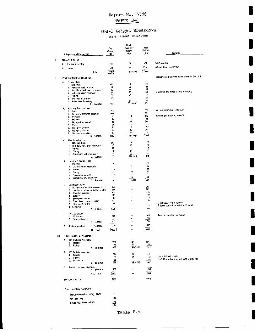
Report No. 3386 TABm B-2
EGS-1 Weight Breakdown
Subsystem and Component
I. NUCLEAR SYSTEM
A. Reactor Assembly
E. Shield
I. Total
E G S - 1 WEIGHT BREAKDOWN
Dry Weight
I lb l
761
I510
L2nll II. POWER CONVERSION SYSTEM
A. Primary L w I NaK PMA 2. Parasitic load resistor 3 Auxiliary start heat exchanger 4. NaK expansion reservoir 5. Piping 6 , Thermal insulation 7. Boiler NaK inventory
A. Subtotal
B. Mercury Rankine Lwp I. Boiler 2. Turbine alternator assembly 3 Condenser 4 HgPM4 5. Hg injection system 6. Valves 1 Hg piping I v a p x l 8. Hg piping l l iquidl 9. Thermal insulation
E. Subtotal
C. Heat Rejection Loop I HRLNaKPMA 2 HRL NaK expansion reservoir 3. Valves 4. Piping 5. Condenser NaK inventory
c. Subtdal
D. Lubricant-Cmlant Lmp I. UCPMA 2. U C expansion reservoir 3 Valves 4. Piping 5. Thermal insulation 6. Component UC inventory
D. Subtotal
I Translormer reactor assembly 2. Low-trmperature control assembly 3. Inverter assembly 4 Batteries 5. Start programmer 6 Power bus, harne5r. misc. 7. SCR speed control 8. Capacitor
E. Electrical Sytlem
L. Subtotal
F PCS Struclure I. PCS lrame 2, Support brackets
F. Subtotal
C. Instrumenlation - Subtotal
11. Tdal
1 1 1 . FLIGHTRADIATOR ASSEMBLY
I. Radiator 2. Piping
A. HRL Radiator Assembly
A. Subldal
E UC Radiatcf Assembly I Radiatw 2. Piping 3. Insulat ion
6. Subtotal
C. Radiator Stringers B riw - Subtdal
I I I. Total
TOTAL tCS WEIGHT
fluid Inventory Summary:
Sodium-Pdassium Alloy N a K l
Mercury tHgl
Pdyphenyl Ether 14P3El
170 61 12 98 33 23
403 -
258 a3 91 85 86 13 51 11 32
1230
170 45 12 M
257
70 35 16 47 33
T5l-
356 m 316 140 I 5 IW
_-
~~
__ 1226
500 235
120
__ - l?
@g
993 M
1023
281 20 A ?B
708
-
~
m 8523
437
189
123 749 -
Flud Inventory
Weigh1 (Ibl -
29
29 INaK)
8 22 10 13 49
56 1581NaKI
I 7
18
58
I 95
-. .. 189 ltql
8 25
36 33
Ik lNaKl
I5
M
10 55 14P3El
~
_ _ ._
_ _
_ _
102
1% I N a K l 48
56 12
64 14P3EI
-_
Table B-2
Wet Weight (Ib)
lpo 1510
123001
178 89 22
111 82 2?
50:
331 603 142 85
144 13 52
106 37
im8
I78 70 12 64
324
20 M 16 77 33 10
206
356 209 316 Id0
15 lull
-
1226
500 235 735
120 ~- ~
lzzl
1095
1173
331 32 98
467
708
78
_-
_ _
r2348) 9272
Remarks
S8DS reactor
Adjusted lor reactor kwt
Components lightened as described in SK. VB
Lightened and sized to loop inventnry
Wet weight includes Item A7
Wet weight includes Item C5
NO^ used i n this syrtem Speed coiitrol included in E l and 2
Tension-member type lrame
10' - Y4" OD x ,035 I /# ' Min-k diaphragm at b a s e d HRL rad.
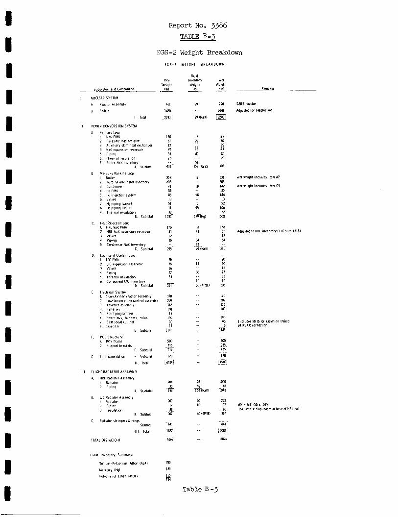
I I I I I 1 I I I I I I I I I I I I I
Report No. 3386 TABLE B - 3
EGS-2 Weight Breakdown E C S - 2
Dry Weiqht
Subsystem and Component l lb l
I NUCLEAR SYSTEM
A Reactor Assembly
B Shield
I Total
II POWER CONVERSION SYSTEM
A Primdry Lmp I NaK PMA 2 Parasitic load resistor 3 Auxiliary start heat exchanger 4 NaK expansion reservoir 5 Piping 6 Thermal insulalion 7 Boiler NaK inventory
A Subtotal
B Mercury Rankine Lmp I Boiler 2 Turbine alternator assembly 3 Condenser 4 Hg PMA 5 Hg injection system 6 Valves 7 Hg piping lvaporl 8 Hq piping (Iiquidl 9 Thermal insulation
B Subtotal
C Heat Rejection Imp I HRLNaKPMA 2 HRL NaK expansion reservoir 3 Valves 4 Piping 5 Condenser NaK inventory
C Subtotal
D Lubricant-Cmlant L q I U C P M 2 UC expansion reservoir 3 Values 4 Piping 5 Thermal insulation 6 Component LIC inventory
0 Subtotal
I Transformer reactor assembly 2 Lowtemperature mntro l assembly ? lnverler assembly 4 RdlteriPs 5 Sldrt prqrammer 6 Power bus harness. rnlsc 7 SCR speed control 8 Cdpacitor
C Electrical System
E Subtotal
f PCS Structure I PCSframe 2 Support brackels
F Subtotal
C Instrumenlation - Subtotal
II Total
I I I I 1 ICHT RADIATOR ASSEMBLY
A HRL Radiator Assembly I Radiator 2 Piping
A Subtotal
E LIC Radiator Assembly I Radiator 2 Piping 3 lnsulal ion
B Subtotal
- Subtotal
Ill Tolal
C Radiator stringers & rings
TOTAL EGS WEIGHT
Fluid Inventory Summary:
Scdium-Potassium Alloy INaKl
Mercury IN1 Polyphenyl Ether W 3 E I
761
1480
[@
170 67 12 98 33 23
403 ~.
258 a3
PI 85 86 13 51 I I
1230
170 43 I2 a
~ 3L
zsr 20 35 16 41 33
151
170 209 31 6 IM I5
90 I5
I I45
500 _ ~ - 235
735
IXI
__
190
1404
904
9?4
202 I7 88-
307
MI
2
[ 18821
8162
430
Iffl
115 734 -
WLlCHT BREAKDOWN
Fluid Inventory
Weight llbl
29
29 (NaKI
8 22 I D 13 49
Ih 158 IN~KI
17
18
58
1 95
1fflmgI
8 24
34 33 99 INaKl .-
15
30
10 55 (4WI
-.
_ _ -
-. _ _ -. -. .. -. -.
-.
_ _
_ _
96 48
144 INaKl
M 10
00 (4P3El .. ~-
_ _
Wel Weight
IIhl ~
7 w
1480
ma 178 89 22
111 82 :) 3
m5
331 003 142 85
144 13 52
106 32
~~ .. I m8
178 67 12 M
321
m
16 77 33 10
2w
I70 209 316 140 15
191)
I5 1145
Mo ~~ 235 ~
735 IM
m
. .-
on ~.
.-
L431
loo0 78
1078
252 27 88
3 7
641 -
i?J W 6
Table B - j
Remarks
S8DS reactor
Adjusted lor reaclw kwt
$Vet weight includes Item A7
Wet weight includes Item C5
Adjusted toHRL inventory(l1C plus I I I A I
Includes 50 Ib lor radiation shield 24 KVAR correction
60' - 314" OD x ,035 114' Min-k ?:;piiragm at b a s e d HRL rad.
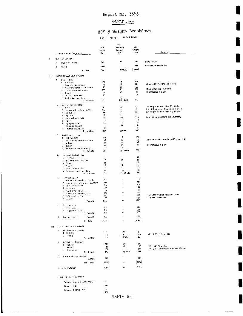
1
Fluid Inventory Summary:
Salium-Potassium Atlny INaKl
Mcrcury It@)
Polyphenyl Ether 14P311
Report No. 3386 TABLE B -4
EGS-3 Weight Breakdown t C S - 3 WEIGHT BREAKDOWN
Dry Wright
llbl __
761
lm,
12361 I
110 9h 12 114 M 25
45 3
M3 613 100 85 88 I 3 51 11 32
I342
170 53 12 35
270
m 35 16 47 33
I51
218 zo9 316 140 I5
190 100 n
1215
5iM 235 735 120
,4230 j
1251 34
1285
2x1 m
126 37h
192
[ 2453j
9 1 M
54 I 205
121 87 3 -
Fluid Inventory
Weight llbl __-
29
29 INaKI
X 44 10 I5 62
72 211 lNdKl
22
21
hh
I 95
a 5 l t q l
n M
43 38
119 lNdKl
I 5
M
IO 55 14P3EI
122
182 INaKl M~
M 12
72 l4P3El
W et Weight
IIbI ~
190
I m ,
r2m 1
178 Id0
22 129 qn .'5
5V2
437 61 3 1 h5 R5 154
1 3 52
I D6 32
1657
178
12 78
351
zo 50 16 77 33 IO
206
83
718 209 31 6 140
15 190 1M 27
1215
5rm 235 735 120
j48761
1373 94
1467
m 32
126 448
792
[ 2707 9973
Table R-lt
Remarks _ _
SBDS reactor
Adlusted lor reactor kwt
Adjusted lor higher pwer rating
Adlusted lor Img inventory OD increased Io 2 25'
W ~ r l weight includes Item A7. 9 tuber Adjusted tor larger flow passages i n TA Wet weight includes Item C5. 05 tubes
Adjuslfd lor increased loop inventory
Adjusted lo HRL inventory I I I C plus I I IA l
OD increased l o 2 25"
Includes 50 Ib for radialion shield 46 KVAR correction
Po' - 2. E' 0.0. x ,035
70' - 314' OD x ,035 114 ' Min-k diaphragm at base 01 HRL rad
I 1 I I I 1 1 I I I 1 I 1 I 1 1 I 1 1
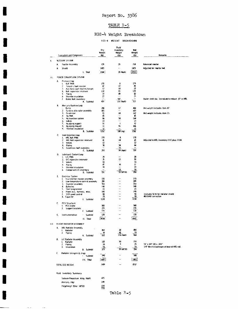
I I I I I 1 D I I 1 I 1 I I I I 8 I I
Report No. 3386
TABLE B-5
EGS-4 Weight Breakdown E G S - 4 WEIGH1 BREAKDOWN
Dry Weqht
IIbl - Subsystem and Component
NUCLfAR SYSTEM
A. Reactor Assembly
E. Shield
I. Total
POWER CONVERSION SYSIEM
A Primarytaop I. NdK PMA 2 Parasitic Id resistor 3 Auxiliary start heat exchanger 4. NaK expansion reservoir 5. Piping 6. Thermal insulation 1. Boiler NaK invenlory
A. Subtotal
E. Mercury Rankine L q I. Boiler 2 Turbine alternator assembly 3. Condenser 4. ng PMA 5. Hg iniectwn system 6. Valves 1. Hg piping Ivaporl 8. Hg piping tliquidl 9. Thermal insulation
E. Subtdal
C. neat Relection L q I. HRL NaKPMA 2. HRL N a K expansion reservoir 3. Valves 4. Piping 5. Condenser NaK inventory
c. Subtdal
0. Lubricant-Coolant Lmp I. UCPMA 2. U C expansion reservoir 3. Valves 4. Piping 5. Thermal insutalion 6. Component LIC inventory
0. Subtotal
I. Trdnslormer rwctor assembly 2. Lowtemperature conlrol assembly 3. Inverter assembly 4. Batteries 5. Start programmer 6. Power bus. hdrness. mlsc. 1. SCR speed contrd 8. Capacitor
E. Electr ial System
E. Subtotal
F. PCS Structure I. PCS frame 2. Support brackets
F. Subtotal
G. Instrumentation - Subtotal
11. Iota1
FLIGHT RADIATOR ASSEMBLY
A. HRL Radiator Assembly I. Radiator 2. Piping
A. Subtotal
E. LIC Radiator Assembly I. Radiator 2. Piping 3. Insulation
E. Subtotal
- Subtotal
Ill. Tdal
C. Radiator stringers 8 rings
TOTAL EGS WEIGHT
Fluid Inventory Summary:
Sodium-Paassium Alloy INaKl
Mercury IHgl
Folyphenyt Ether 14P3EI
129
1475
[??%I
170 67 I 2
114 33 23
4L9
280 to3 91 85 86 13 51 I I 32
1252
170 41 I2 a
253
20 35 16 47 33
151
170 m 316 140 I 5
190 90 28
1158
m -23.
735
Izo
~-
-
-
~-
- -.
$4
m2 x)
832
183 16 76
275
590
_--
- mi1 7989
41 5
189
114 178 -
Fluid I nvrntor y
Weight I l b l
~
29 _ _ 29 INaKl
8 22 IO I5 49
101 211 INaKl
-.
17
18
58
1 95
_ _ _ _ _ _
- 189ltQl
8 24
34
W I N a K I
-.
33
15
M
IO 55 14P3El
-.
_ _ ._
_ _ _ _ _ _ _ _
_ _
88 48
m
136 INaKl
9 -. - 9 l4P3EI
_ _
Table €3-5
Wd Weqht
IIbI
758
m 1475
178
n 129 82 23
523
m
-
604 to3 142 a5
144 13 52
106 32
1581
178 65 12 64
319
20
16 71 33 10
206
110 209 316 140 I 5
190 W 28
1158
Mo
735
120
_ _ -
m
_ _
2)5
- _ _
14642]
890
968
233 25 16
334
YM
78
~ ~-
[El m67
Remarks
Akanced reaciw
Adiurted lw r e c t o r kwt
Boiler shell dia. incrmsrd to reduce dP in HRL
Wet w i g h t includes Item A7
Wet weqht includes Item C5
Adjusted to HRL i n v e n t w y l l l C plus IIIAI
Includes M Ib tw radiatw shield 48 KVAR correction
55' x 314" OD x ,035" 114' Min-k diaphragm at base d HRL rad
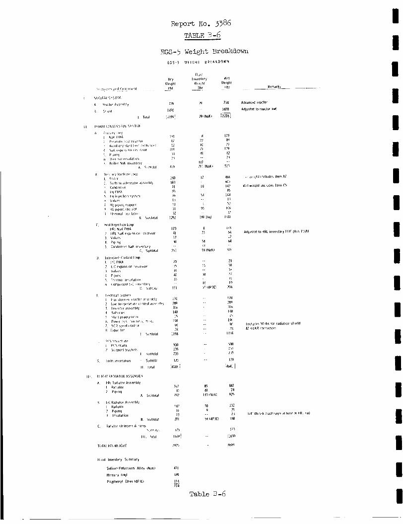
~ e p o r t NO. 3 9 6 TABLE B-6_
EGS-5 Weight Breakdown L G S - 5 W f l G H I B R t A K D O W N
c Ranlator strinqer5 R rinqs ~ l 1 l 1 l O I d l
1 1 1 lo td l
TOTAL l C S WEIGHT
f l u i d Inventory Summary
Scdium-Potassium Alloy INdKl
Mercury lHgl
PolflhPnyl Ether 14P3tl
Dry
l!t!L
Neight
729
I 4111
' Z I W :
I10 61 I ?
114 33 ?i
41V
2RO tdj3 91 R5 835 I 3 51 I I 12
I252
I10 41 12 a
753
20 15 10 47 33
I51
1 i n m 31 b 100
I 5
90 28
1158
m 235 135
la
190
1
767 Y)
792
182 10 13
271
515
' 1 0 3 8
1925
471
189
114 714 -
Fluid I nurntory
Wuiilhl l l h l
29
29 INaKI
X 22 10 I 5 49
i n i 211 INaKl
17
I X
5R
I 95
1.69 iHy1
8 ? 3
34 33 98 lNdKl
I 5
85 48
133 lNdKl
50 9
59 14P3El
w PI Weight
l lh l ~
758
1470
I 2 4
116 89 22
IT? R2 24
5 2
404 N13 142
R5 144
1 i 52
IO6 32
I ' m
liR M 12 64
)in
m 50 16 17 33 10
206
I in 20) 316 100
1') 1911
2R ll5R
m 735 135
120
r4MI 1
9n
847 1R
925
232 75 73
330
515
l18@
Ro99
Remarks __
Advancrd reactor
Adlusted to reaclOr kw(
, I A + iqhl includes Item A7
wt wqh l includes Item CS
Adpr l t d to HRL inventory l l l c phis I l l A l
Includes Y) Ibs lor rddldtlon shield 41 KVAR coirrctlon
1 1 4 ' Min-k dldphrdgm d l u s e of HRL rad
Table B-6
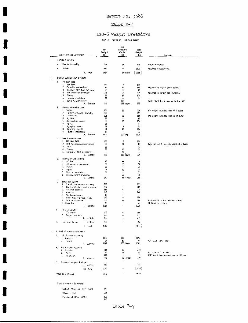
Report No. 3386 TABLE B-7
EGS-6 Weight Breakdown E G S - 6
Dry Weight
I l b l __
779
1600
12329 1
170 96 12
I 3 8 P) 21
482
356 61 3 106 85 88 I 3 51 I I 32
i 355
170 52 12 35
269
20 35 16 41 33
151 ~
223 201 316 140 I 5
190 1w 42
1235
5M1 235 135
I20 43dl
~~
i i x i 34
1217
21R .m
119 351
7 67
i ~
V l l l l
b10
205
127 m
WEIGHT BREAKDOWN
Fluid Inventory
Weight (Ibl
29
29 INaKI
8 44 10 I 9 69
I 3 R ~ 288 INaKl
22
21
66
I 95
2OZIHgl
8 29
43
118 INaKi 38-
15
M
'0- 55 14P3El
115 60
175 tNaKl
60 12
72 14P3LI
W d Weight
l lb l
158
1600
1 2 5 8 )
178 140 22
157 IOU 21
632
516 61 3 I65 85
154 13 52
106 32
I13h
I I 8 81 12 78
3.19
20 M 16 77 33 I O
206
223 m 31 h 140
I I
190 Io(1 42
1235
5w 235 135
IX) I ' 1M1'I
1298 94
I392
27 8 32
119 129
767
[2588'
9959
Subsystem and Component
I. NUCLEAR SYSTEM
A. RPdCtOr Assembly
6. Shield
I. Total
11. POWER CONVERSION SYSTEM
A. Primary Loop I. NaK PMA 2 Parasitic load resistor 3. Auxiliary start heal exchanger 4. NaK expansion reservoir 5. Piping 6. Thermal insulation 7. Boiler NaK inventory
A Subtotal
B Mercury Rankine Loop I. Boiler 7 Turbine alternator assembly 3 Condenser 4 Hg PMA 5. tlg injpction system h Valves 7 Hg piping lvaporl 8 Hg piping II iquidI 9. Thermal insulation
E. Subtotal
C Heat Rejection Loop I. HRL NaK PMA 2. HRL NaK expansion reservoir 3. Valves 4. Piping 5. Condenser NaK invenlory
C. Subtotal
D Lubricant-Coolant Lmp I. U C P M A 2. UC expansion reservoir 3. Valves A Piping 5 lhvrrndl insulation 6 . Component LIC invenlory
D Subtotal
E EleLtrical System I Tramformer reactor dssembly 2 I ow-ItmDPrdture control assemblv
Remarks
Advanced reactor
Adjusled to reactor kwt
Adjusted lor higher power rating
Adjusted lor larger loop inventory
Boiler shell dia. increased lor low A P
Wet weight includes Item A7. 9 tubes
Wet weight includes Item C5. 63 tuhes
Adjusted to HRL inventory ( I IC plus I I I A l
3 Inverter dssembly 4 Ratterier 5 5tdrt prqrammer 6 i'owtr thus harness 1 \ C R s p w J iontrol X Cdpdritor
L
I P( 5 5 t r u i t i i r r I rc5 trdmP 2 5upporl hidikP1s
I
6 In\ l rumentdl ion
II
I l l I L I C H I K A n l A l O R ASSlMBLV
A HRL Rddldtor A\wmbly I Rddldlol 2 Pipinq
A
6 L C Radiator Assembly I Radiator 2 Piping 1 Insulation
B
Incliidiss 50 Ibs tor radiation shield 71 KVAR correction
40' - 2 ? 5 ' OD x .03Y'
70' - 314, o D x 015' 114' Min-k dlaphraqm at base 01 HRL rad
C Rddialor str inqrrs & rings Sii l i total
I II M a l
TOlAL fG5 WEIGHT
Fluid Inventory Summary
Scdium-Potassium Alloy INaKI
Mercury tHgl
Polyphenyl Ether t4P3El
Table B-7
Report No. 3386
APPENDIX C
ANALYSIS OF TURBINE E F F I C D N C Y A S AF.E3CTED BY PRESSURE RATIO AND NUMBER OF STAGES
me SNAP-8 performance po ten t i a l s tudy requi res ana lys i s of t h e system per -
formance when the turb ine i n l e t and ou t l e t pressures are changed.
ob ta in more accura te r e su l t s , it was necessary t o eva lua te the e f f e c t of changing
p r e s m r e s on tu rb ine e f f i c i ency .
I n order t o
I n order t o minimize the turbine modif icat ion required, it was assumed t h a t
Thus, only blade p r o f i l e s , t k e t u rb ine and wheel p i t ch diameters a r e he ld constant .
flow a r e a s , and number of pressure s tages were considered. The number of pressure
s tages recpired i s based on the overa l l p ressure r a t i o , t he r e s u l t i n g b lade v e l o c i t y
to nozzle e x i t v e l o c i t y (u/c) r a t i o and the nozzle area r a t i o requirements.
eva lua t ion was based on the equations i n AGC TM 394:63-1-112. e f f ic i8ncy i s :
The
The o v e r a l l
- c ' 7 s
'T - (mad )T where
= s t age e f f i c i ency ?s
(AH ) = i s en t rop ic enthalpy change i n s t age
(A2 ) = i s en t rop ic enthalpy change for e n t i r e tu rb ine pressure r a t i o
ad s
ad T
The equat ion f o r s tage e f f i c i ency is :
where n r e f e r s t o s tage number
= s t age diagram ef f ic iency ? h i
% = q u a l i t y of mercury vapor a t s t age i n l e t
Ls = s e a l losses f a c t o r
Alls = scavenging loss
A$ = blade pumping loss
Analysis of Turbine Efficiency as Affected by Pressure Ratio and Number of Stages (cont. )
A? = loss due t o l i q u i d mercury i n vapor
AT = d i s k f r i c t i o n lo s s
m
d
The equations defining these terms follow:
Report No. 3386
where
u = blade ve loc i ty - f t / s e c
= i d e a l nozzle ve loc i ty =J2"(&ad)S - f t / s e c
= blade ve loc i ty c o e f f i c i e n t
% = t i p leakage co r rec t ion f a c t o r
Kf = f i l l i n g and emptying loss f a c t o r
$, = nozzle v e l c c i t y c o e f f i c i e n t
cO
$B
Q: = nozzle ang le 1
I n t h i s ana lys i s , t he following design parameters were held constant :
Wheel p i t c h diameter = 5 . 1 inches
R P M = 12,000
Radial t i p c learance = 0.040 inch
Blade v e l o c i t y coef. = 0.8203 ( f i rs t s t age )
Nozzle v e l o c i t y coef. = 0.9459 Nozzle ang le cosine = 0.956
KL = 0.7709
S u b s t i t u t i n g these values i n t o t h e s t a g e diagram e f f i c i e n c y expression and re-
l r - 1 - 2.166 2.86
- .. .
c -2
Analysis of Turbine Eff ic iency as Affected by Report No. 3386 Pressure Ratio and Number of Stages (cont. )
The value of ($1, t o be used i n evaluat ing t h i s expression, i s given by:
and
where
t = blade p i t c h = 0.2025 inch
a = a r c l eng th f o r each admission a r c
np = number of admission a r c s = 2 f o r 1s t s t age
N
D = wheel p i t c h diameter inches
W = admission a r c f r a c t i o n s 26 5 5 = 0.38 x 11,200 P
where
0.38 = admission a r c f r a c t i o n f o r 265 ps i a t u r b i n e i n l e t pressure and 11,200 lb /h r mercury flow; P4 i s new i n l e t pressure; and new flow rate.
i s
Subs t i t u t ing and simplifying
2.81 ~4 (K-& = 1 - - W
where N i s t h e number of s tages . Using these two expressions, t h e equation f o r ST t h e f i rs t s t age diagram e f f i c i e n c y becomes :
2.166 (NsT)
(mad L
Analysis of Turbine Eff ic iency as Affected by Pressure Ratio and Number of Stages (cont. )
Report No. 3386
The pumping losses for t he f i r s t s t age i s given by
l/NST (1.383 - 0.01048
p4 = 0.00045
where P5 i s t h e turbine exhaust pressure.
The d i s c losses a r e given by:
l’NST = 0.000383
I
1 1
With these equations t o so lve f o r t he m l u e s , t h e equation f o r the f i r s t s t a g e
e f f i c i e n c y which follows can be evaluated f o r d i f f e r e n t i n l e t pressures and flow
r a t e s .
Th? ana lys i s i s now c a r r i e d out f o r t he second s t a g e , using the second s t age 1 constants as follDws:
The equation for t h e second s t a g e diagram e f f i c i e n c y becomes:
1/2 2.86 NST
/ A U \ - 1 i 1
c-4 I 1
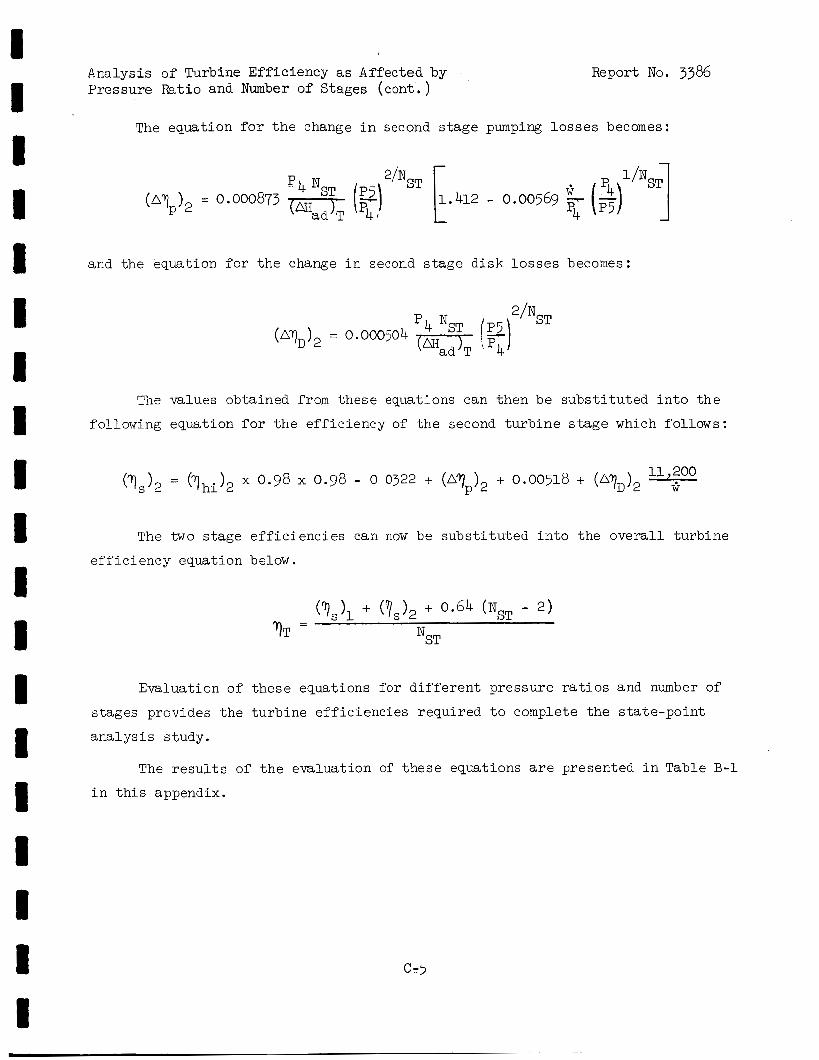
I
Analysis of Turbine Efficiency as Affected by Pressure Ratio and Number of Stages (cont. )
Report No. 3386
The equation for t h e change i n second stage pumping l o s s e s becomes:
-
P4NST (p5) 2’NST k .412 - 0.00569 (2) l/NST 1 a Tf p4
(A? ) = 0.000873 P 2
and the equation f o r t h e change i n second s t age d i s k l o s s e s becomes:
P N 4 ST [Q(hsT
‘.p4 = 0.000504
The values obtained from t hese equations can then be subs t i t u t ed i n t o t h e
following equation f o r t h e e f f i c i e n c y of t he second t u r b i n e s t a g e which follows:
The two s t age e f f i c i e n c i e s can now be s u b s t i t u t e d i n t o t h e o v e r a l l t u rb ine
e f f i c i e n c y equation below.
Evaluation of t hese equations f o r d i f f e r e n t pressure r a t i o s and number of
s tages provides t h e tu rb ine e f f i c i e n c i e s required t o complete the s t a t e -po in t
a n a l y s i s study.
The r e s u l t s of t h e evaluat ion of t hese equations are presented i n Table B-1 i n t h i s appendix.
c-5
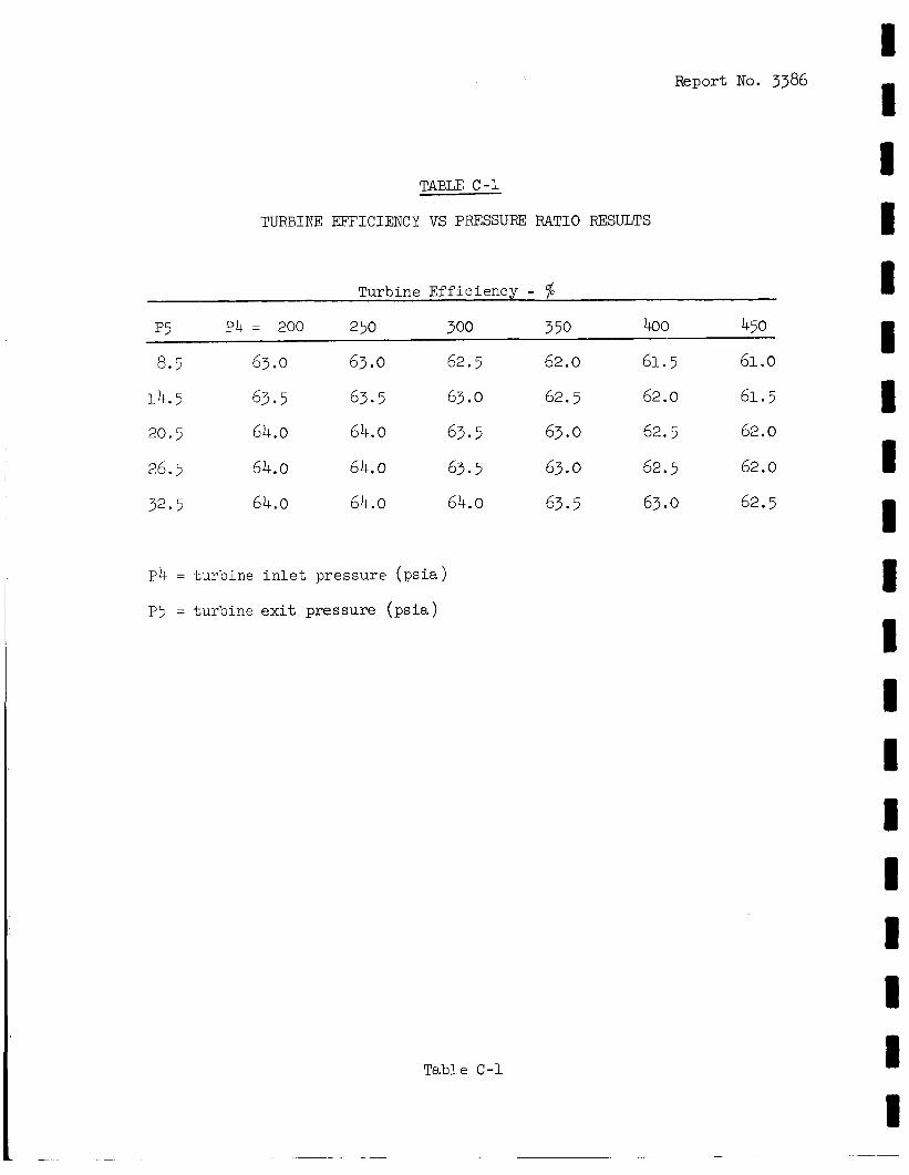
Report No. 3386
TABLE C -1
TURBINE EFFICIENCY VS PRESSUm RATIO RESULTS
Turbine Eff ic iency - % p5 P4 = 200 2 50 300 3 50 400 450
~~
8.5 63.0 63.0 62.5 62.0 61.5 61.0
14.5 63.5 63.5 63.0 62.5 62.0 61.5
20.5 64.0 64.0 63.5 63.0 62.5 62.0
26.5 64.0 64.0 63.5 63.0 62.5 62.0
32.5 64.0 64.0 64.0 63.5 63.0 62.5
P4 = tu rb ine i n l e t p ressure ( p s i a )
P5 = tu rb ine e x i t pressure ( p s i a )
Table C-1
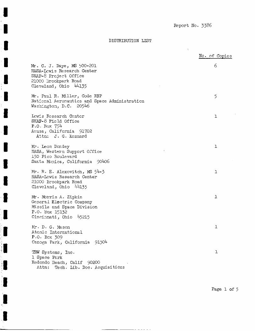
DISTRIBUTION LIST
M r . C . J. Daye, Ms 500-201 NASA-Lewis Research Center SNAP-8 P ro jec t Office 21003 Brookpark Road Cleveland, Ohio 44135
M r . Paul R . Mil ler , Code RNP National Aeronautics and Space Administration Washington, De C . 20546 Lewis Research Center SNAP-8 Fie ld Office P.O. Box 754 Azusa, Cal i forn ia 91702
Attn: J. G. Kennard
Mro Leoc Dondey NASA, Western Support Office 150 Pic0 3oulevard Sar,ta Mor?_ica, Cal i forn ia 90406
M r o R. E. Alexovitch, Ms 54-3 NASA-Lewis Research Center 21000 brookpark Road Cleveland, Ohio 44135
M r o Morris A . Zipkin General E l e c t r i c Company Missi le and Space Division P.O. Box 15132 C i n c i m a t i , Ohio 45215
D. G. Mason Atomic In t e rna t iona l P.O. Box 309 Canoga Park, Cal i forn ia 91304
TRW Systems, Inc. 1 Space Park Redoido Beach, Calif 90200
Attn: Tech. Lib. Doc. Acquisit ions
Report No. 3386
I
No. of CoDies
6
1
1
1
1
1
Page 1 of 5
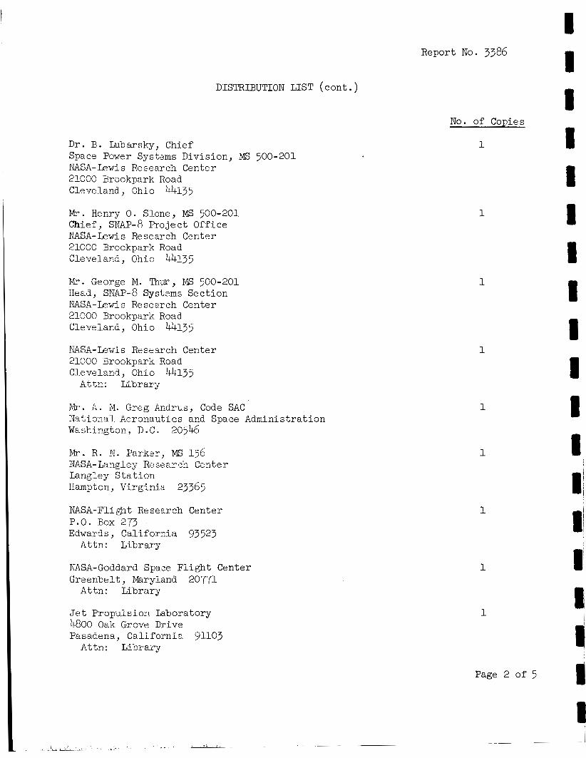
Report No. 3386
DISTRIBUTION LIST (cont . )
Dr. B. Lubarsky, Chief Space Power Syskms Division, Ms 500-201 NASA- k w i s Re search Center 21000 Brookpark Road Cleveland, Ohio 44135
I&. Henry 0 . Slone, Ms 500-201 Chief, SNAP-8 Project Office NASA-Lewis Research Center 21000 Brockpark Road Cleveland, Ohio 44135
M r . George M. Thw, MS 500-201 Read, SNAP-^ Systems Sect ion NASA-Lewis Research Center 21000 Brookpark Road Cleveland, Ohio 44135
NASA-Lewis Research Center 21000 Brookpark Road C l e v e l a ~ d , Ohio 44135
A t t - : Kbrarjr
M r . A . M. Greg Ardrus, Code SAC Natiora.1 Aeronautics and Space Administration Washicgton, D . C . 20546
M r . R . 3. Parker, MS 156 NASA-Langley R?search Center Langley S t a t i o n Hampton, Virginia 23365
NASA-Flight Research Center P.O. Box 273 Edwards, Ca l i fo rc i a 93523
Attn: Library
NASA-Goddard Space F l i g h t Center Greenbelt, Maryland 20771
Attn: Library
J e t Propulsion Laboratory 4800 Oak Grove Drive Pasadena, Cal i fornia 91103
Attn: Library
No. of Copies
1
1
1
1
1
I u 1 1 1 i I I B I I I I i I 1 I I I
M r e J e r r y P. Davis J e t Propulsion Laboratory 4800 Oak Grove Drive Pasadena, Cal i fornia 91103
Report No. 3386
DISTRIBUTION LIST ( cont . )
M r . Roger Arno
NASA-Arne3 Research Center Moff2tt F ie ld , Cal i fornia 94035
m a g . ~ 2 0 2 - 9
Mru R . W . Schaupp NASA-Ames Research Center
Moffett F ie ld , Cal i fornia 94035 ~ a i i s t op 202-7
D r . Joseph LaFleur AEX Headquarters Space Nuclear Systems Division Washingtor, D o C . 20545
I@- Carl Johnson AEC Headquarters Space Nuclear Sys terns Division Washicgton, D.C . 20545
M r . S t a n R. Stamp U.S. .Atomic Energy Commission Canoga Park, Cal i fornia 91304
Director of Development Depar'tment of the A i r Force AFRDD, The Pentagon Washington, D.C. 20301
Director of Science and Technology Department of the A i r Force AFRST, The Pentagon Washirgton, D.C. 20301
No. of Copies
1
1
1
1
1
1
1
1
Aer 0- Pr opul s i on Iab or a t ory Wright Pat terson AFB Dayton, Ohio 45433
Page 3 of 5
DISTRIBUTION LIST ( c o n t . )
Cmdr. Marvin C . D e m l e r Research & Technology Division Boll ing AFB Washington, D.C. 20332
M r - B. J . Crowe Communications Systems Inc. 5718 Colunibia Pike, P.O. Box 530 F a l l s Church, Virginia 22046
Mr Vern D e Kirklarzd, Program Manager Power Systems, Advanced Manned Spacecraft Systems Douglas A i r c r a f t Company 5301 Bolsa Avenue Huntington Beach, Cal i fornia 92606 .
Mr- M. H . Greenfield Lockheed Missile and Space Company P.O. Box 504 Silxyvale , Cal i forgia 94086
M r - Joseph Doss Boeicg Compacy P.O. Box 3737 S e a t t l e , Washington 98124
Mr- ,James Hadley Lawre Ii 2 2 Rad I a t i on Labor a t ory University of' Cal i fornia Berkeley, Cal i fornia 94720
M r . Robert Thorpe General E l e c t r i c Company P.O. BOX 8555 Phi ladelphia , Pennsylvania l 9 l O l
Mr. A . J. Miller Oak Ridge Natioyal Laboratory Oak Ridge, Tennessee 37830
Mr. T o q Redding, EP5 NASA-Manned Spacecraft Center 2101 Webster Seabrook Road Houston,, Texas 77058
1
1
1
1
Report No. 3386
1 1 1 1 1 1 1 1 1 1 1 t 1 1 1
Page 4 of 5 1
No. of Copies
1
Report No. 3386
DISTRIBUTION LIST (cont . )
M r . Gordon Woodcock, R-AS NASA-Marshall Space F l igh t Center Huntsvi l le , Alabama 35812
M r . Ca r ro l l Dailey NASA-Marshall Space F l i g h t Center Huntsv i l le , Alabama 35812
NASA-Ele c t ron ic s Re search Center 575 Technology Square Cambridge, Massachusetts 02139
Attn: Library
NASA-John F. Kennedy Space Center Kennedy Space Center, Flor ida 32899
Attn: Code ATS-132
National Aeronautics and Space Administration Washington, D.C . 20546
Attn: Library Code USS-10
Nat ional Aeronautics and Space Administration L e w i s Research Center 21000 Brookpark Road Cleveland, Ohio 44135
Attn: V . Hlavin, Mail Stop 3-14
National Aeronautics and Space Administration L e w i s Research Center 21000 Brookpark Road Cleveland, Ohio 44135
Attn: M. Sabala, Mail Stop 3-19
Nat ional Aeronautics and Space Administration Lewis Re search Center 21000 Brookpark Road Cleveland, Ohio 44135
Attn: J . Di l ley , Mail Stop 500-309
NASA S c i e n t i f i c and Technical Information F a c i l i t y P . O . Box 33 College Park, Maryland 20740
I n t e r n a l
No. of Copies
1
1
1
1
1
1
26
Page 5 of 5