Embed Size (px)
Citation preview
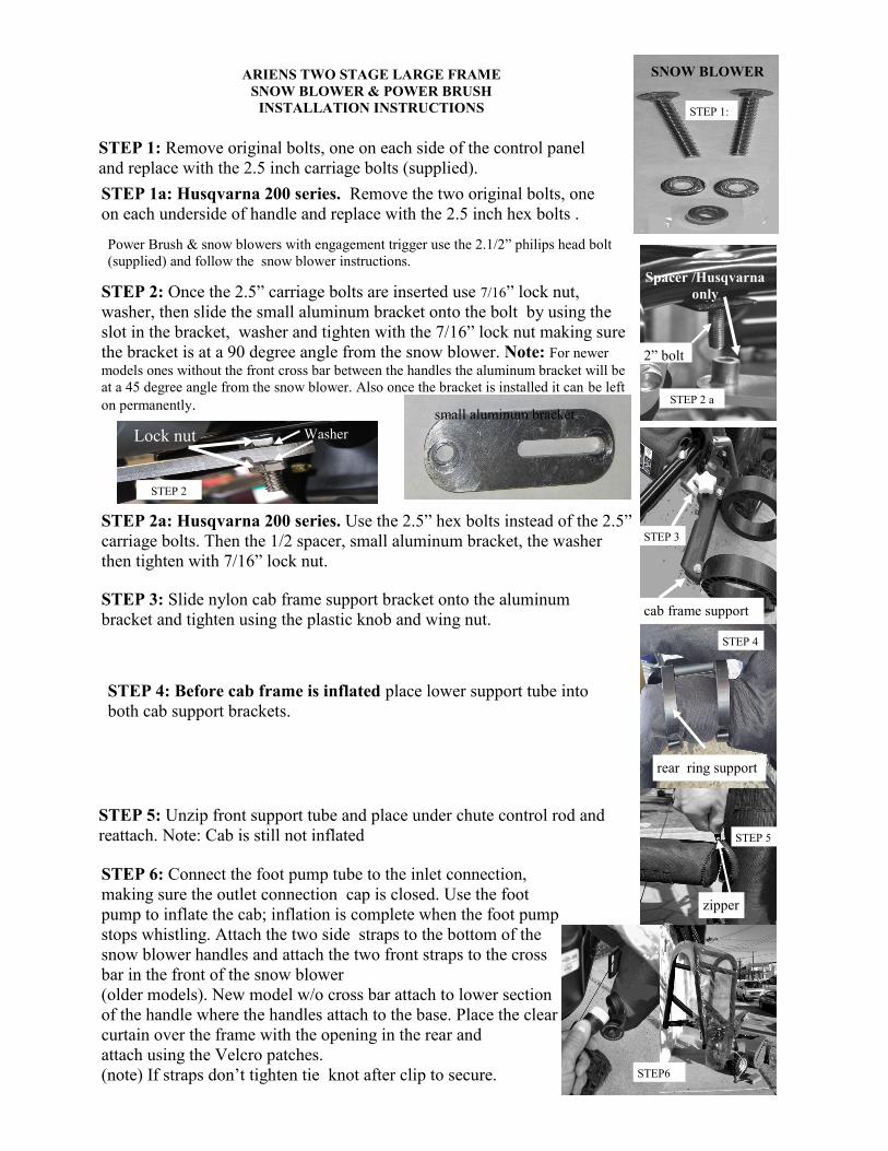
STEP 1: Remove original bolts, one on each side of the control panel
and replace with the 2.5 inch carriage bolts (supplied).
SNOW BLOWER ARIENS TWO STAGE LARGE FRAME
SNOW BLOWER & POWER BRUSH
INSTALLATION INSTRUCTIONS
STEP 2 a
STEP 3: Slide nylon cab frame support bracket onto the aluminum
bracket and tighten using the plastic knob and wing nut.
STEP 3
cab frame support
Spacer /Husqvarna
only
2” bolt
STEP 4: Before cab frame is inflated place lower support tube into
both cab support brackets.
STEP 4
rear ring support
STEP 5: Unzip front support tube and place under chute control rod and
reattach. Note: Cab is still not inflated STEP 5
zipper
STEP 6: Connect the foot pump tube to the inlet connection,
making sure the outlet connection cap is closed. Use the foot
pump to inflate the cab; inflation is complete when the foot pump
stops whistling. Attach the two side straps to the bottom of the
snow blower handles and attach the two front straps to the cross
bar in the front of the snow blower
(older models). New model w/o cross bar attach to lower section
of the handle where the handles attach to the base. Place the clear
curtain over the frame with the opening in the rear and
attach using the Velcro patches.
(note) If straps don’t tighten tie knot after clip to secure.
Power Brush & snow blowers with engagement trigger use the 2.1/2” philips head bolt
(supplied) and follow the snow blower instructions.
small aluminum bracket
STEP 2a: Husqvarna 200 series. Use the 2.5” hex bolts instead of the 2.5”
carriage bolts. Then the 1/2 spacer, small aluminum bracket, the washer
then tighten with 7/16” lock nut.
STEP 1a: Husqvarna 200 series. Remove the two original bolts, one
on each underside of handle and replace with the 2.5 inch hex bolts .
STEP 1:
STEP6
STEP 2: Once the 2.5” carriage bolts are inserted use 7/16” lock nut,
washer, then slide the small aluminum bracket onto the bolt by using the
slot in the bracket, washer and tighten with the 7/16” lock nut making sure
the bracket is at a 90 degree angle from the snow blower. Note: For newer
models ones without the front cross bar between the handles the aluminum bracket will be
at a 45 degree angle from the snow blower. Also once the bracket is installed it can be left
on permanently.
Lock nut Washer
STEP 2
PASO 1: Retire los pernos originales, uno en cada lado del panel de
control y reemplazar con los tornillos de doble rosca de 2.5 pulgadas
(suministrados).
PASO 1a: Husqvarna serie 200. Retire los dos tornillos originales, uno en cada lado
inferior del mango y vuelva a colocar los tornillos hexagonales con 2.5".
Poder del cepillo y sopladoras de nieve con el compromiso de disparo
utilizan el tornillo de cabeza Philips 2.1 / 2 "(suministrado) y siga las
instrucciones de soplador de nieve.
PASO 2: Una vez que los tornillos de doble rosca 2.5 "se insertan uso de
7/16" tuerca, arandela, a continuación, deslice el soporte de aluminio
pequeña en el perno mediante el uso de la ranura de la abrazadera, la
arandela y apretar con el 7/16 "bloquear la toma de tuerca de que el
soporte está en un ángulo de 90 grados desde el soplador de nieve.
Nota: Para los modelos más nuevos sin la barra transversal frontal en-
tre las manijas del soporte de aluminio será en un ángulo de 45 grados
desde el soplador de nieve. También una vez que se instala el soporte se
Tuerca de bloqueo Lavadora
PASO:2
soporte de aluminio pequeña
SOPLADOR DE NIEVE
PASO 1:
PASO 2 a
Espaciador/
Husqvarna
2” Tornillo
PASO 3
apoyo bastidor de la cabina
PASO 4
soporte de la corona
PASO 5
cremallera
PASO:6
Paso 2a: Husqvarna serie 200. Utilice la opción "pernos hexagonales
en lugar de los 2.5" 2 pernos del carro. A continuación, el espaciador
de 1/2, soporte de aluminio pequeña, la arandela de apriete con 7/16
PASO 3: cabina de nylon soporte de la ayuda del marco de diapositiva
en el soporte de aluminio y apretar con el botón de plástico y la tuerca
de mariposa.
PASO 4: Antes de bastidor de la cabina es el lugar inflado tubo de
soporte inferior en dos abrazaderas de soporte de la cabina.
PASO 5: Descomprimir tubo de soporte frontal y de lugar en la barra
de control del canal y vuelva a conectar. Nota: Cab todavía no se infla
PASO 6: Conectar el tubo de la bomba de pie a la conexión de en-
trada, por lo que la tapa de conexión de salida está cerrada. Utilice la
bomba de pie para inflar la cabina; la inflación se ha completado
cuando la bomba de pie deja de silbar. Una las dos tiras de velcro lado
a la parte inferior de los mangos soplador de nieve y adjuntar las dos
tiras de velcro frontal a la barra transversal en la parte delantera del
soplador de nieve (modelos antiguos). Nuevo modelo w / o barra trans-
versal adjuntar a la sección inferior del mango, donde las asas se fijan
a la base. Coloque la cortina transparente sobre el marco con la aber-
tura en la parte trasera yfije utilizando los parches de velcro.
ARIENS DE DOS ETAPAS marco grande Soplador de
nieve y CEPILLO ELÉCTRICO INSTRUCCIONES
DE INSTALACIÓN
STEP6
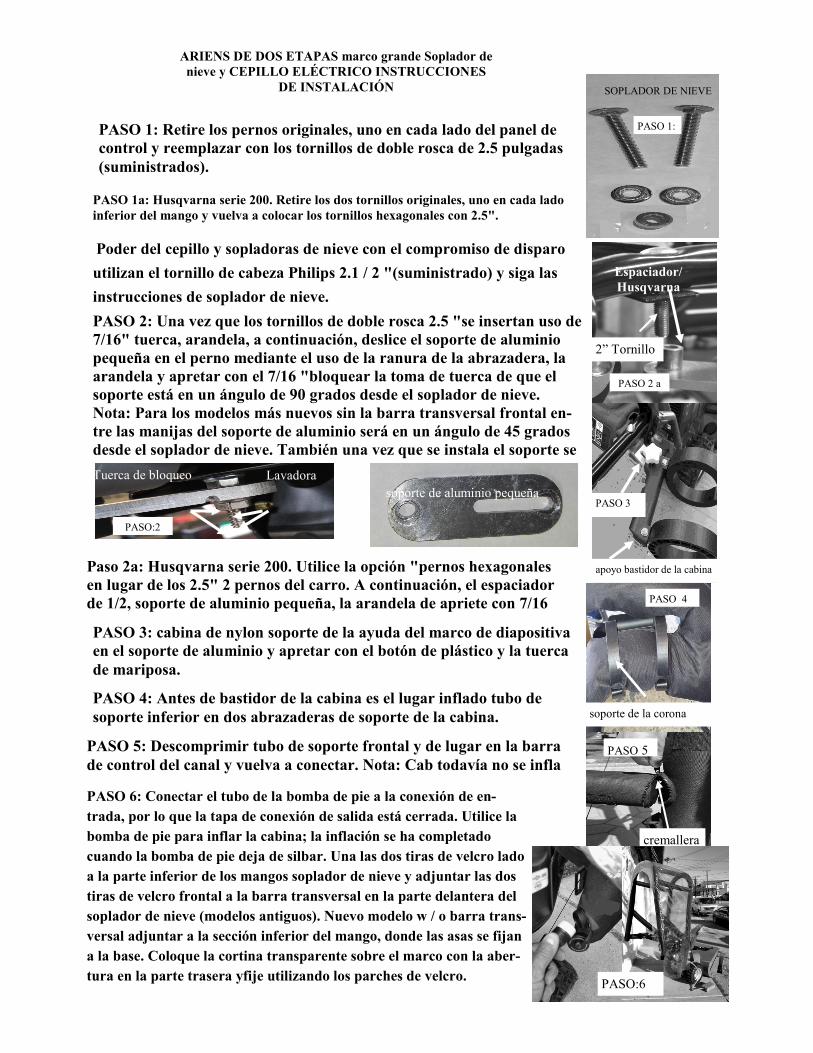
MTD, MTD PRO, MTD GOLD, CUB CADET, YARDMAN,TROY BUILT, YARD MACHINE,REMINGTON
& COLUMBIA TWO LARGE FRAME SNOW BLOWERS INSTALLATION INSTRUCTIONS
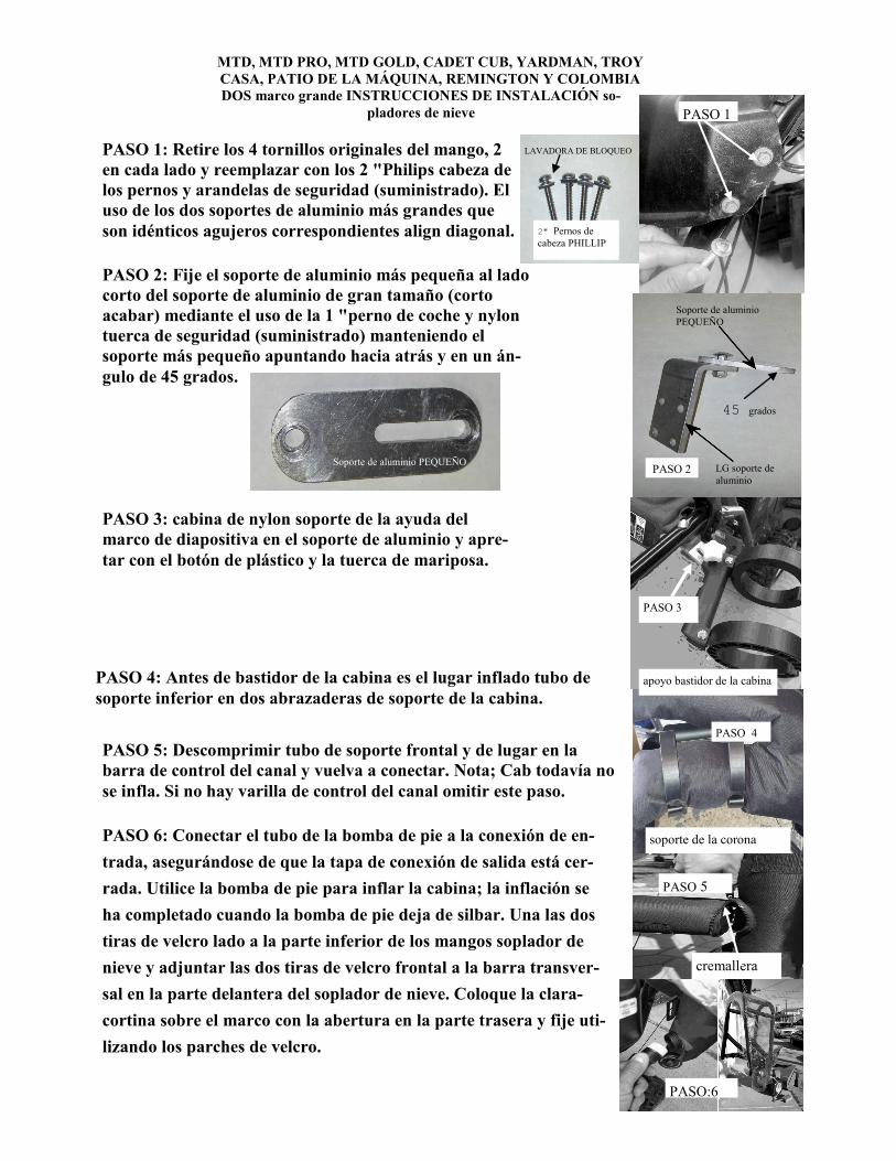
STEP 1: Remove the 4 original bolts from handle, 2 on
each side and replace with the 2” philips head bolts and
lock washers (supplied). Using the two larger aluminum
brackets which are identical align corresponding holes
diagonally.
STEP 1
2" PHILLIP
LOCK WASHER
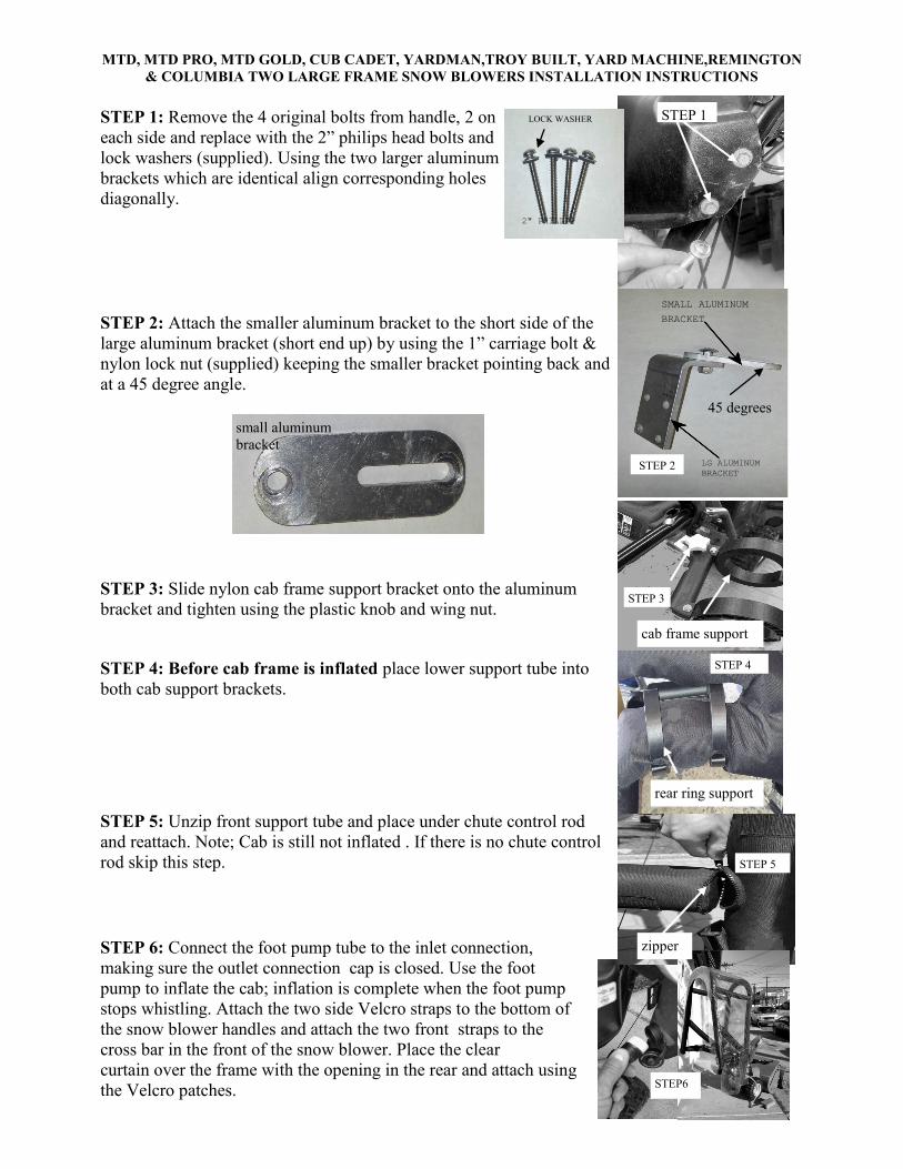
STEP 2: Attach the smaller aluminum bracket to the short side of the
large aluminum bracket (short end up) by using the 1” carriage bolt &
nylon lock nut (supplied) keeping the smaller bracket pointing back and
at a 45 degree angle.
LG ALUMINUM
BRACKET
SMALL ALUMINUM
BRACKET
STEP 2
STEP 3: Slide nylon cab frame support bracket onto the aluminum
bracket and tighten using the plastic knob and wing nut. STEP 3
cab frame support
STEP 4: Before cab frame is inflated place lower support tube into
both cab support brackets.
STEP 5: Unzip front support tube and place under chute control rod
and reattach. Note; Cab is still not inflated . If there is no chute control
rod skip this step.
STEP 6: Connect the foot pump tube to the inlet connection,
making sure the outlet connection cap is closed. Use the foot
pump to inflate the cab; inflation is complete when the foot pump
stops whistling. Attach the two side Velcro straps to the bottom of
the snow blower handles and attach the two front straps to the
cross bar in the front of the snow blower. Place the clear
curtain over the frame with the opening in the rear and attach using
the Velcro patches.
45 degrees
STEP 4
rear ring support
STEP 5
zipper
small aluminum
bracket
MTD, MTD PRO, MTD GOLD, CADET CUB, YARDMAN, TROY
CASA, PATIO DE LA MÁQUINA, REMINGTON Y COLOMBIA
DOS marco grande INSTRUCCIONES DE INSTALACIÓN so-
pladores de nieve PASO 1
2" Pernos de
cabeza PHILLIP
LAVADORA DE BLOQUEO PASO 1: Retire los 4 tornillos originales del mango, 2
en cada lado y reemplazar con los 2 "Philips cabeza de
los pernos y arandelas de seguridad (suministrado). El
uso de los dos soportes de aluminio más grandes que
son idénticos agujeros correspondientes align diagonal.
PASO 2: Fije el soporte de aluminio más pequeña al lado
corto del soporte de aluminio de gran tamaño (corto
acabar) mediante el uso de la 1 "perno de coche y nylon
tuerca de seguridad (suministrado) manteniendo el
soporte más pequeño apuntando hacia atrás y en un án-
gulo de 45 grados.
LG soporte de
aluminio
Soporte de aluminio
PEQUEÑO
PASO 2
45 grados
Soporte de aluminio PEQUEÑO
PASO 3: cabina de nylon soporte de la ayuda del
marco de diapositiva en el soporte de aluminio y apre-
tar con el botón de plástico y la tuerca de mariposa.
PASO 4
soporte de la corona
PASO 3
apoyo bastidor de la cabina PASO 4: Antes de bastidor de la cabina es el lugar inflado tubo de
soporte inferior en dos abrazaderas de soporte de la cabina.
PASO 5: Descomprimir tubo de soporte frontal y de lugar en la
barra de control del canal y vuelva a conectar. Nota; Cab todavía no
se infla. Si no hay varilla de control del canal omitir este paso.
PASO 5
cremallera
PASO 6: Conectar el tubo de la bomba de pie a la conexión de en-
trada, asegurándose de que la tapa de conexión de salida está cer-
rada. Utilice la bomba de pie para inflar la cabina; la inflación se
ha completado cuando la bomba de pie deja de silbar. Una las dos
tiras de velcro lado a la parte inferior de los mangos soplador de
nieve y adjuntar las dos tiras de velcro frontal a la barra transver-
sal en la parte delantera del soplador de nieve. Coloque la clara-
cortina sobre el marco con la abertura en la parte trasera y fije uti-
lizando los parches de velcro.
PASO:6
SIMPLICITY,JOHN DEERE,BRIGGS & STRATTON & SNAPPER
INSTALLATION INSTRUCTIONS
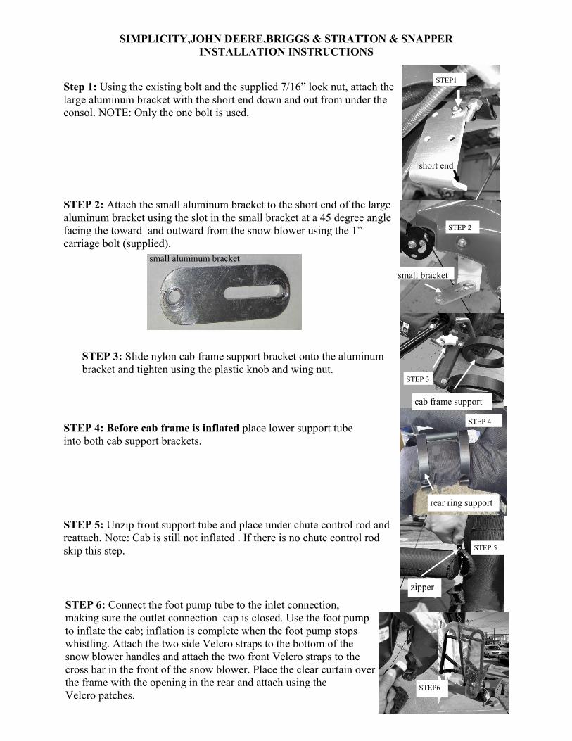
Step 1: Using the existing bolt and the supplied 7/16” lock nut, attach the
large aluminum bracket with the short end down and out from under the
consol. NOTE: Only the one bolt is used.
STEP1
short end
STEP 2: Attach the small aluminum bracket to the short end of the large
aluminum bracket using the slot in the small bracket at a 45 degree angle
facing the toward and outward from the snow blower using the 1”
carriage bolt (supplied).
STEP 2
small bracket
STEP 3: Slide nylon cab frame support bracket onto the aluminum
bracket and tighten using the plastic knob and wing nut. STEP 3
cab frame support
STEP 4: Before cab frame is inflated place lower support tube
into both cab support brackets.
STEP 5: Unzip front support tube and place under chute control rod and
reattach. Note: Cab is still not inflated . If there is no chute control rod
skip this step.
STEP 6: Connect the foot pump tube to the inlet connection,
making sure the outlet connection cap is closed. Use the foot pump
to inflate the cab; inflation is complete when the foot pump stops
whistling. Attach the two side Velcro straps to the bottom of the
snow blower handles and attach the two front Velcro straps to the
cross bar in the front of the snow blower. Place the clear curtain over
the frame with the opening in the rear and attach using the
Velcro patches.
STEP 4
rear ring support
STEP 5
zipper
small aluminum bracket
STEP6
SENCILLEZ, John Deere, Briggs & Stratton y
MORDEDORES INSTRUCCIONES DE INSTALACIÓN
Paso 1
extremo corto
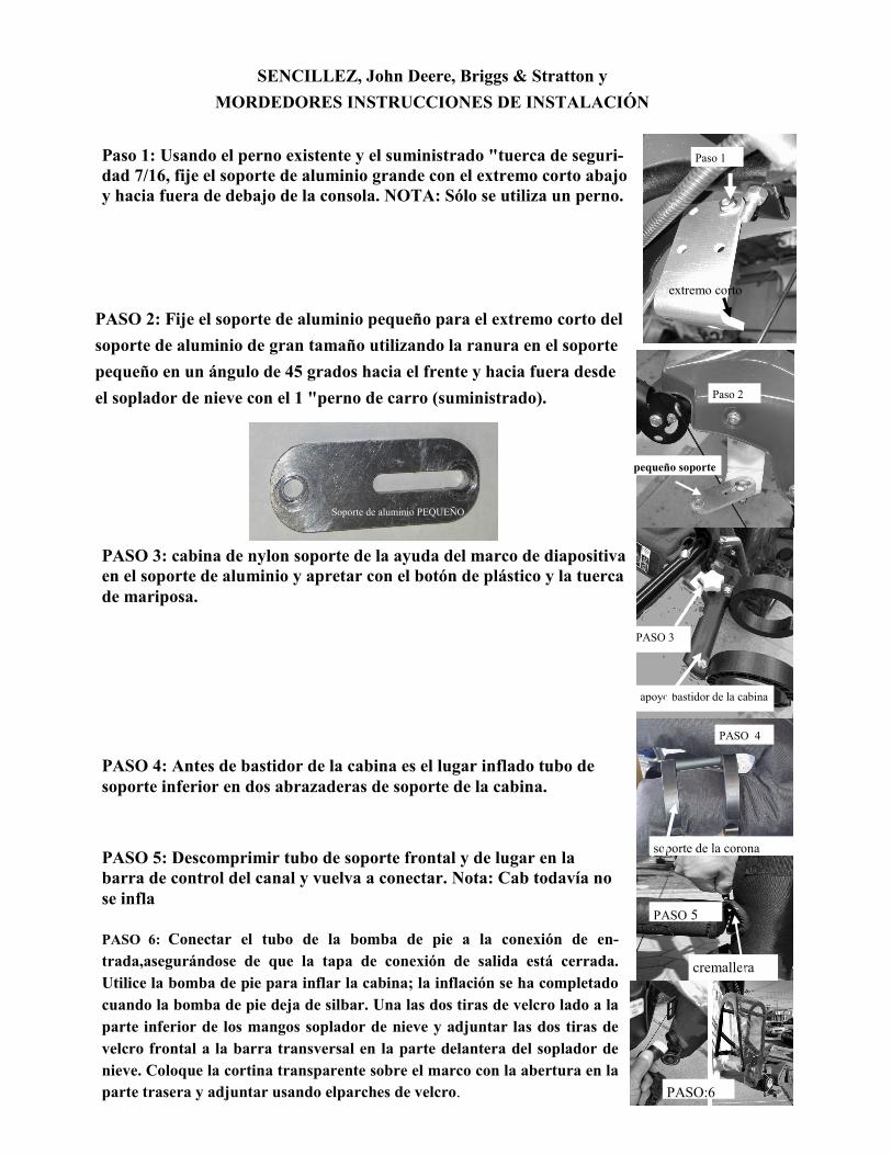
Paso 1: Usando el perno existente y el suministrado "tuerca de seguri-
dad 7/16, fije el soporte de aluminio grande con el extremo corto abajo
y hacia fuera de debajo de la consola. NOTA: Sólo se utiliza un perno.
Paso 2
pequeño soporte
PASO 2: Fije el soporte de aluminio pequeño para el extremo corto del
soporte de aluminio de gran tamaño utilizando la ranura en el soporte
pequeño en un ángulo de 45 grados hacia el frente y hacia fuera desde
el soplador de nieve con el 1 "perno de carro (suministrado).
Soporte de aluminio PEQUEÑO
PASO 3: cabina de nylon soporte de la ayuda del marco de diapositiva
en el soporte de aluminio y apretar con el botón de plástico y la tuerca
de mariposa.
PASO 3
apoyo bastidor de la cabina
PASO 4
soporte de la corona
trasera
PASO 4: Antes de bastidor de la cabina es el lugar inflado tubo de
soporte inferior en dos abrazaderas de soporte de la cabina.
PASO 5
cremallera
PASO 5: Descomprimir tubo de soporte frontal y de lugar en la
barra de control del canal y vuelva a conectar. Nota: Cab todavía no
se infla
PASO:6
PASO 6: Conectar el tubo de la bomba de pie a la conexión de en-
trada,asegurándose de que la tapa de conexión de salida está cerrada.
Utilice la bomba de pie para inflar la cabina; la inflación se ha completado
cuando la bomba de pie deja de silbar. Una las dos tiras de velcro lado a la
parte inferior de los mangos soplador de nieve y adjuntar las dos tiras de
velcro frontal a la barra transversal en la parte delantera del soplador de
nieve. Coloque la cortina transparente sobre el marco con la abertura en la
parte trasera y adjuntar usando elparches de velcro.
TORO,POWER MAX HD, POWER CLEAR & SNOW MASTER
INSTALLATION INSTRUCTIONS
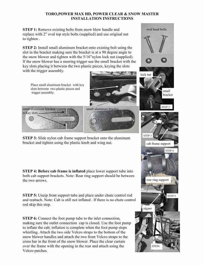
STEP 1: Remove existing bolts from snow blow handle and
replace with 2” oval top style bolts (supplied) and use original nut
to tighten .
oval head bolts
STEP 2: Install small aluminum bracket onto existing bolt using the
slot in the bracket making sure the bracket is at a 90 degree angle to
the snow blower and tighten with the 5/16”nylon lock nut (supplied).
If the snow blower has a steering trigger use the small bracket with the
key slots placing it between the two plastic pieces, keying the slots
with the trigger assembly.
STEP 2
lock nut
STEP 3: Slide nylon cab frame support bracket onto the aluminum
bracket and tighten using the plastic knob and wing nut.
STEP 3
cab frame support
STEP 4: Before cab frame is inflated place lower support tube into
both cab support brackets. Note: Rear ring support should be between
the two arrows.
STEP 5: Unzip front support tube and place under chute control rod
and reattach. Note: Cab is still not inflated . If there is no chute control
rod skip this step.
STEP 6: Connect the foot pump tube to the inlet connection,
making sure the outlet connection cap is closed. Use the foot pump
to inflate the cab; inflation is complete when the foot pump stops
whistling. Attach the two side Velcro straps to the bottom of the
snow blower handles and attach the two front Velcro straps to the
cross bar in the front of the snow blower. Place the clear curtain
over the frame with the opening in the rear and attach using the
Velcro patches.
STEP 4
rear ring support
STEP 5
zipper
STEP6
small aluminum bracket
w/key slots
small aluminum bracket
small
bracket
Place small aluminum bracket with key
slots between two plastic pieces and
trigger assembly.
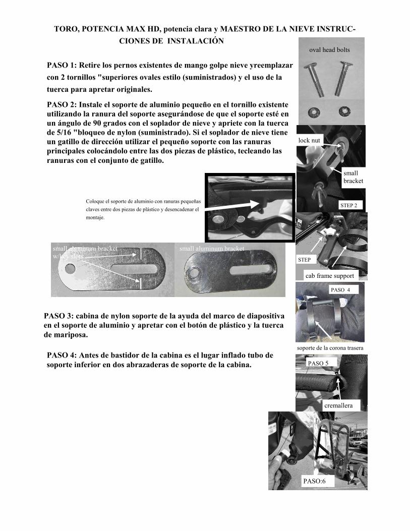
TORO, POTENCIA MAX HD, potencia clara y MAESTRO DE LA NIEVE INSTRUC-
CIONES DE INSTALACIÓN oval head bolts
STEP 2
lock nut
small
bracket
STEP
cab frame support
PASO 4
soporte de la corona trasera
PASO 5
cremallera
PASO:6
PASO 1: Retire los pernos existentes de mango golpe nieve yreemplazar
con 2 tornillos "superiores ovales estilo (suministrados) y el uso de la
tuerca para apretar originales.
PASO 2: Instale el soporte de aluminio pequeño en el tornillo existente
utilizando la ranura del soporte asegurándose de que el soporte esté en
un ángulo de 90 grados con el soplador de nieve y apriete con la tuerca
de 5/16 "bloqueo de nylon (suministrado). Si el soplador de nieve tiene
un gatillo de dirección utilizar el pequeño soporte con las ranuras
principales colocándolo entre las dos piezas de plástico, tecleando las
ranuras con el conjunto de gatillo.
Coloque el soporte de aluminio con ranuras pequeñas
claves entre dos piezas de plástico y desencadenar el
montaje.
small aluminum bracket
w/key slots
small aluminum bracket
PASO 3: cabina de nylon soporte de la ayuda del marco de diapositiva
en el soporte de aluminio y apretar con el botón de plástico y la tuerca
de mariposa.
PASO 4: Antes de bastidor de la cabina es el lugar inflado tubo de
soporte inferior en dos abrazaderas de soporte de la cabina.
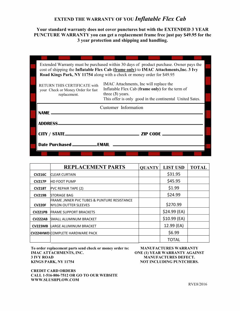
Customer Information
NAME
ADDRESS
CITY / STATE ZIP CODE
Date Purchased EMAIL
EXTEND THE WARRANTY OF YOU Inflatable Flex Cab
Your standard warranty does not cover punctures but with the EXTENDED 3 YEAR
PUNCTURE WARRANTY you can get a replacement frame free just pay $49.95 for the
3 year protection and shipping and handling.
Extended Warranty must be purchased within 30 days of product purchase. Owner pays the
cost of shipping the Inflatable Flex Cab (frame only) to IMAC Attachments,Inc. 3 Ivy
Road Kings Park, NY 11754 along with a check or money order for $49.95
RETURN THIS CERTIFICATE with
your Check or Money Order for fast
replacement.
IMAC Attachments, Inc will replace the
Inflatable Flex Cab (frame only) for the term of
three (3) years.
This offer is only good in the continental United Sates.
REPLACEMENT PARTS QUANTY LIST USD TOTAL
CV216C CLEAR CURTAIN $31.95
CV217P HD FOOT PUMP $45.95
CV218T PVC REPAIR TAPE (2) $1.99
CV219B STORAGE BAG $24.99
CV220F FRAME ,INNER PVC TUBES & PUNTURE RESISTANCE NYLON OUTTER SLEEVES $270.99
CV221PB FRAME SUPPORT BRACKETS $24.99 (EA)
CV222AB SMALL ALUMINUM BRACKET $10.99 (EA)
CV223MB LARGE ALUMINUM BRACKET 12.99 (EA)
CV224HWD COMPLETE HARDWARE PACK $6.99
TOTAL
To order replacement parts send check or money order to:
IMAC ATTACHMENTS, INC.
3 IVY ROAD
KINGS PARK, NY 11754
CREDIT CARD ORDERS
CALL 1-516-806-7512 OR GO TO OUR WEBSITE
WWW.SLUSHPLOW.COM
MANUFACTURES WARRANTY
ONE (1) YEAR WARRANTY AGAINST
MANUFACTURES DEFECT.
NOT INCLUDING PUNTCHERS.
RVE8/2016