Embed Size (px)
Citation preview
SOCIETÀ COOPERATIVA
BILANCIAI
Terminal D410
Use, maintenance and installation manual
Code 813722 EDITION 30 May 2001

Index12. SAFETY INSTRUCTIONS FOR THE INSTALLER 3-5
13. OPENING THE TERMINAL 3-713.1 Opening the outer casing 3-713.2 Main parts of the terminal 3-813.3 Removal of the power supplier 3-913.4 Removal of the converter 3-1013.5 Removal of the CPU 3-1213.6 Removal of the display 3-1313.7 Replacing the keypad 3-1413.8 Replacing the lithium battery 3-1513.9 Installing the MPP board 3-1713.10 Installing optional boards 3-1913.11 Installing the optional 4 I/O board 3-1913.12 Installing the optional serial ports board 3-2013.13 Installing the optional BCD parallel 5V-calculator board 3-2013.14 Installing the optional BCD parallel 24V-source board 3-21
14. PERSONALIZING METROLOGICAL PARAMETERS 3-2314.1 Calibration button 3-2314.2 Description of the main menus and metrological parameters 3-25
14.2.1 Setup Menu/Scale/Configurations/Metrological 3-2614.2.2 Setup Menu/ANALOGUE scale/Analogue scale parameters 3-2914.2.3 Setup Menu/DIGITAL scale/Digital scale parameters 3-2914.2.4 Setup Menu/Scale/Calibration/Execute 3-2914.2.5 Setup Menu/Scale/Calibration/Display data 3-3314.2.6 Setup Menu/Scale/Calibration/Correction 3-3314.2.7 Setup Menu/DIGITAL scale/Calibration/Angle calibr. 3-3514.2.8 Setup Menu/DIGITAL scale/Test 3-3914.2.9 Setup Menu/DIGITAL scale/Test/Terminal data storage 3-4014.2.10 Setup Menu/DIGITAL scale/Test/Terminal data reinstatement 3-40
14.3 Repeater scale 3-4114.3.1 Setup Menu/Scale/Repeater scale parameters/Serial port/String
3-41
15. SOFTWARE UPGRADE 3-4315.1 Setup Menu/Upgrade 3-43
15.1.1 Setup Menu/Upgrade/Serial line 3-4415.1.2 Upgrade via upgrade board 3-46
16. MAINTENANCE 3-4916.1 Setup Menu/Maintenance 3-49
17. TROUBLESHOOTING 3-5317.1 CPU and converter faults 3-5417.2 Management of errors by peripheral devices 3-57
D410
3-3

D410
3-4
12. SAFETY INSTRUCTIONS FOR THEINSTALLER
CAUTION The information and instructions contained in this section areaddressed exclusively to installation personnel who musthave specialised knowledge in the fields of electrical andelectronic engineering and programming.A number of the operations described herein require theremoval of legal seals and the opening of the terminalcasing.Furthermore, certain operations can be only performed whenthe terminal is connected to the electrical power supply.In this condition, some of the exposed electrical componentswill be live and consequently there is a risk of electric shock.Any dismantling or opening of the terminal by the user or anyother unauthorised person shall immediately invalidate thewarranty and release the Manufacturer from all liability forany personal injury or damage sustained.Also consult the "Safety instructions" " chapter of the usermanual.
D410
3-5

D410
3-6
13. OPENING THE TERMINAL
13.1 Opening the outer casing
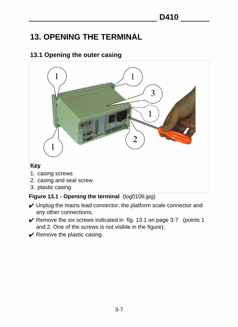
Key1. casing screws2. casing and seal screw3. plastic casing
Figure 13.1 - Opening the terminal (log0106.jpg)
✔ Unplug the mains lead connector, the platform scale connector andany other connections;
✔ Remove the six screws indicated in fig. 13.1 on page 3-7 (points 1and 2. One of the screws is not visible in the figure);
✔ Remove the plastic casing.
D410
3-7
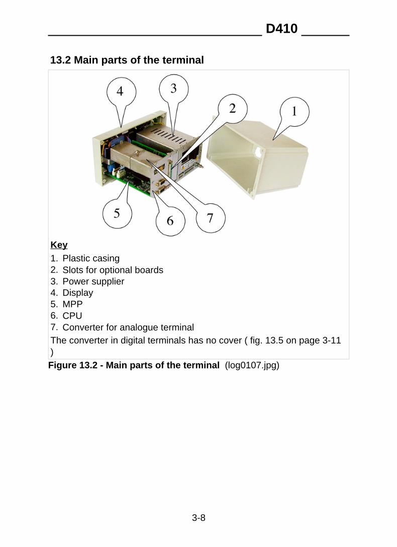
13.2 Main parts of the terminal
Key1. Plastic casing2. Slots for optional boards3. Power supplier4. Display5. MPP6. CPU7. Converter for analogue terminalThe converter in digital terminals has no cover ( fig. 13.5 on page 3-11)Figure 13.2 - Main parts of the terminal (log0107.jpg)
D410
3-8
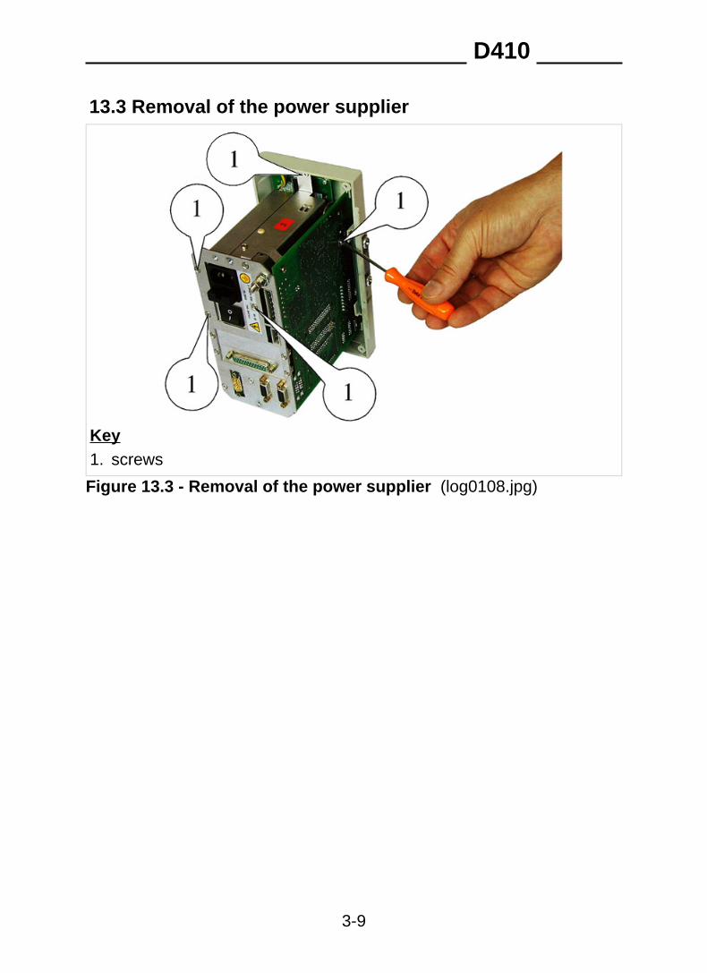
13.3 Removal of the power supplier
Key1. screws
Figure 13.3 - Removal of the power supplier (log0108.jpg)
D410
3-9
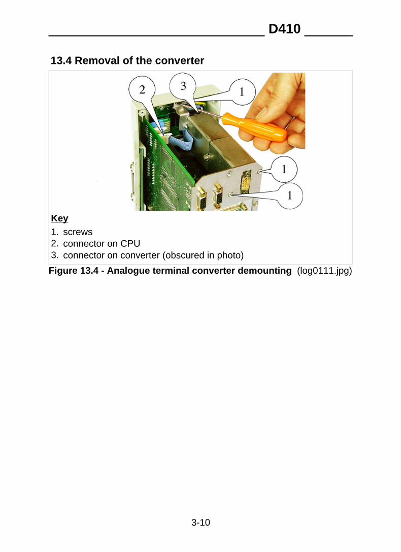
13.4 Removal of the converter
Key1. screws2. connector on CPU3. connector on converter (obscured in photo)
Figure 13.4 - Analogue terminal converter demounting (log0111.jpg)
D410
3-10
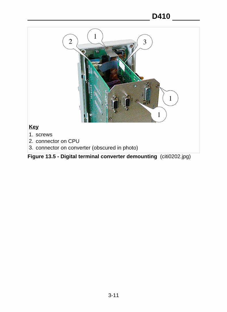
Key1. screws2. connector on CPU3. connector on converter (obscured in photo)
Figure 13.5 - Digital terminal converter demounting (citi0202.jpg)
D410
3-11
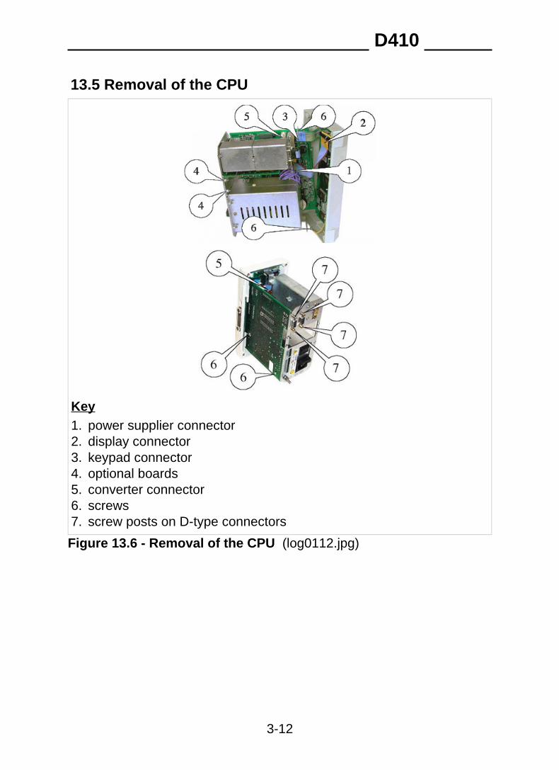
13.5 Removal of the CPU
Key1. power supplier connector2. display connector3. keypad connector4. optional boards5. converter connector6. screws7. screw posts on D-type connectors
Figure 13.6 - Removal of the CPU (log0112.jpg)
D410
3-12
To remove the CPU board, proceed as follows:
✔ remove any optional boards from slots 1 and 2 ( fig. 13.10 on page3-17 );
✔ disconnect the connectors (points 1, 2, 3, 5 of fig. 13.6 on page 3-12);
✔ unscrew the screws (points 6 of fig. 13.6 on page 3-12 ) and screwposts (points 7 of fig. 13.6 on page 3-12 ).
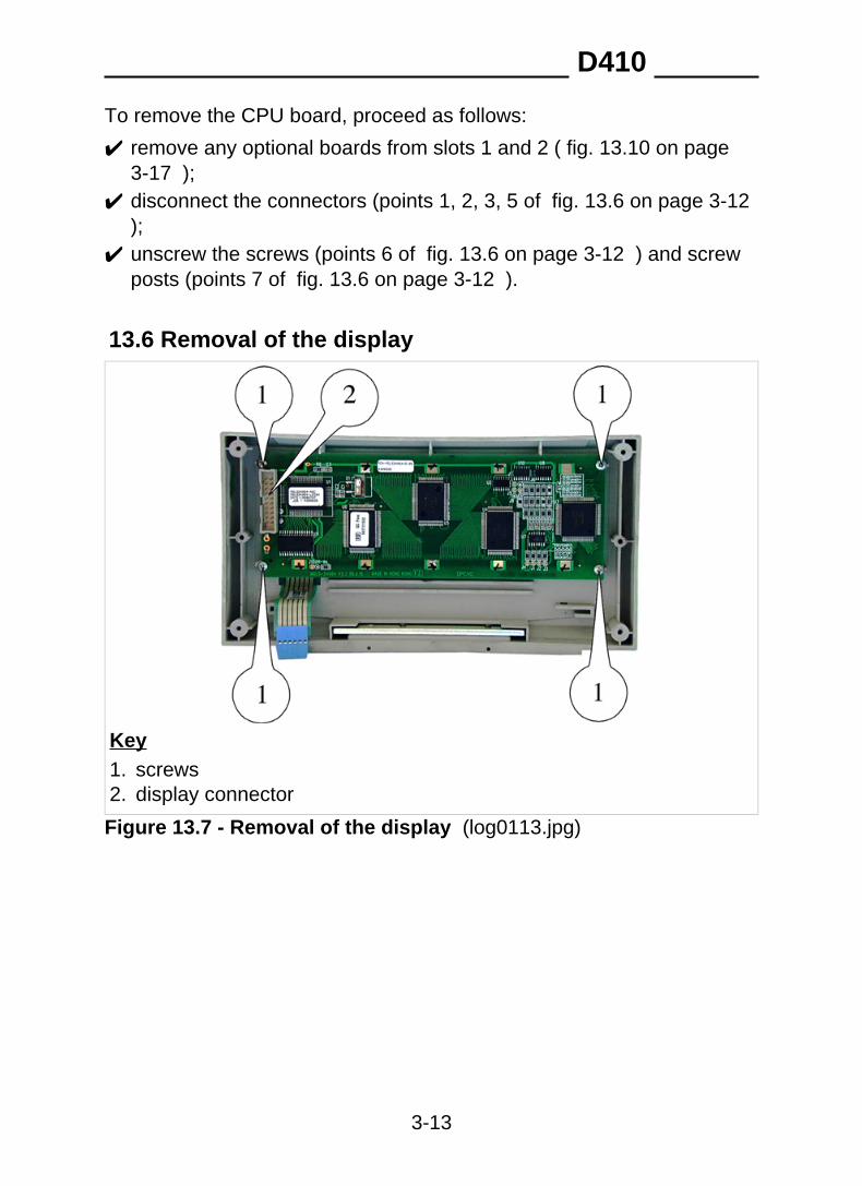
13.6 Removal of the display
Key1. screws2. display connector
Figure 13.7 - Removal of the display (log0113.jpg)
D410
3-13
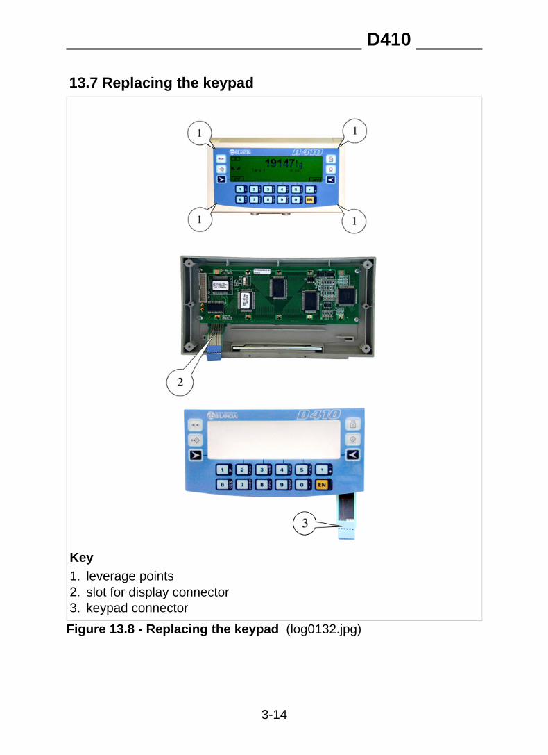
13.7 Replacing the keypad
Key1. leverage points2. slot for display connector3. keypad connector
Figure 13.8 - Replacing the keypad (log0132.jpg)
D410
3-14
✔ Apply leverage using a screwdriver, for example, at points 1.✔ Unstick the keypad.✔ Remove all glue residue with alcohol.✔ Take care not to get alcohol anywhere other than the contact
surfaces and take care not to damage the seal labels. Allow thecontact surface to dry.
✔ Insert the connector in slot 2 and stick the keypad down, positioning itcarefully in the centre of its housing.
13.8 Replacing the lithium batteryTo replace the lithium battery proceed as follows:
✔ switch off the terminal and disconnect the mains lead;✔ open the terminal as indicated in par. 13.1 on page 3-7 ;✔ remove the power supplier ( par. 13.3 on page 3-9 );✔ reconnect the mains lead and switch the terminal on (the battery must
be replaced when the terminal is powered on to prevent loss of data);✔ remove the battery from the battery holder (point 1 fig. 13.9 on page
3-16 );
DANGER Take care not to cause short-circuits between the metalcomponents.
✔ fit a charged battery. Only use a lithium CR2045 battery;✔ dispose of the old battery in accordance with applicable regulations.
Do not dispose of it improperly.
D410
3-15
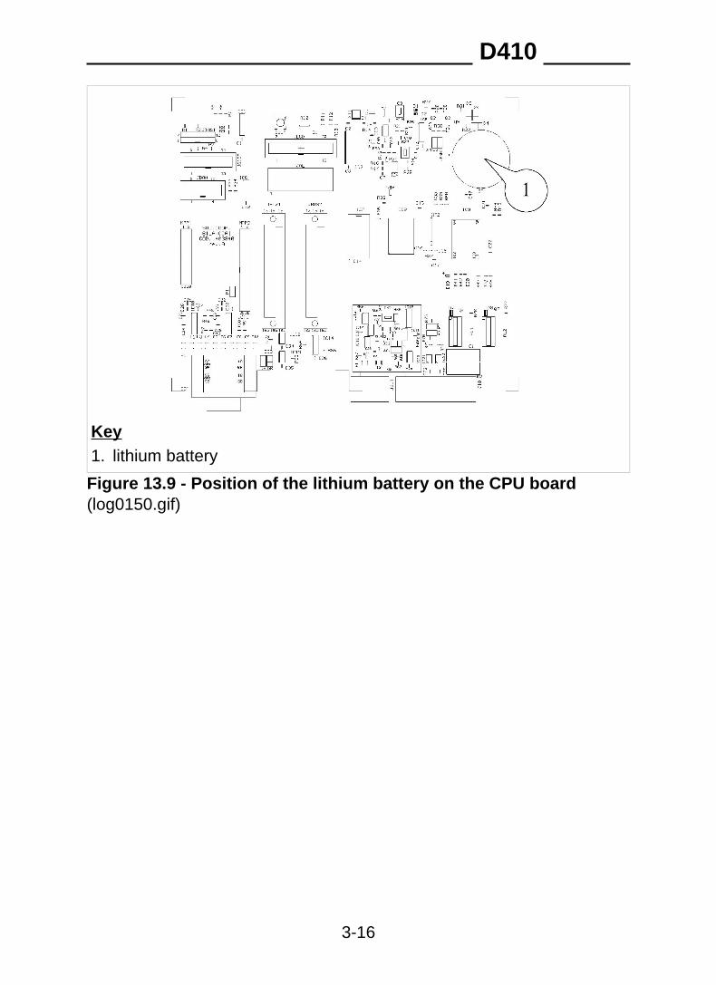
Key1. lithium battery
Figure 13.9 - Position of the lithium battery on the CPU board(log0150.gif)
D410
3-16
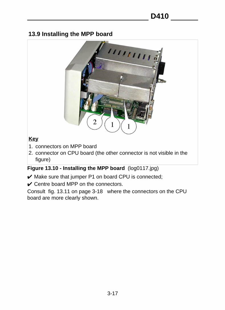
13.9 Installing the MPP board
Key1. connectors on MPP board2. connector on CPU board (the other connector is not visible in the
figure)
Figure 13.10 - Installing the MPP board (log0117.jpg)
✔ Make sure that jumper P1 on board CPU is connected;✔ Centre board MPP on the connectors.Consult fig. 13.11 on page 3-18 where the connectors on the CPUboard are more clearly shown.
D410
3-17
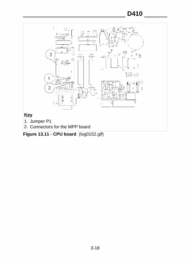
Key1. Jumper P12. Connectors for the MPP board
Figure 13.11 - CPU board (log0152.gif)
D410
3-18
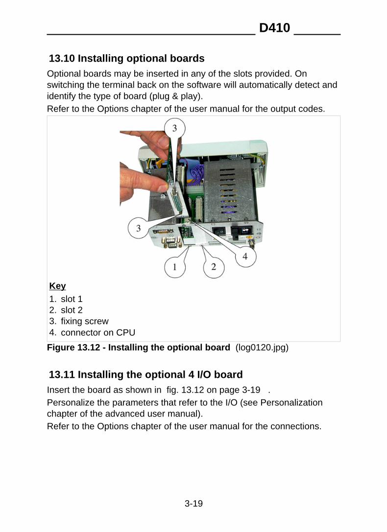
13.10 Installing optional boardsOptional boards may be inserted in any of the slots provided. Onswitching the terminal back on the software will automatically detect andidentify the type of board (plug & play).Refer to the Options chapter of the user manual for the output codes.
Key1. slot 12. slot 23. fixing screw4. connector on CPU
Figure 13.12 - Installing the optional board (log0120.jpg)
13.11 Installing the optional 4 I/O boardInsert the board as shown in fig. 13.12 on page 3-19 .Personalize the parameters that refer to the I/O (see Personalizationchapter of the advanced user manual).Refer to the Options chapter of the user manual for the connections.
D410
3-19
13.12 Installing the optional serial ports boardInsert the board as shown in Figure 13.12 on page 3-19 .Personalize the serial port parameters (consult Personalization chapterof advanced user manual).See Options chapter of the user manual for the connections.
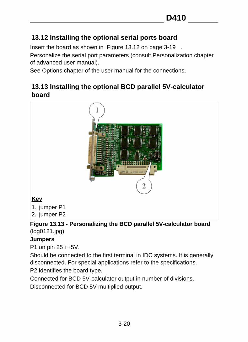
13.13 Installing the optional BCD parallel 5V-calculatorboard
Key1. jumper P12. jumper P2
Figure 13.13 - Personalizing the BCD parallel 5V-calculator board(log0121.jpg)JumpersP1 on pin 25 i +5V.Should be connected to the first terminal in IDC systems. It is generallydisconnected. For special applications refer to the specifications.P2 identifies the board type.Connected for BCD 5V-calculator output in number of divisions.Disconnected for BCD 5V multiplied output.
D410
3-20
Personalize the relative parameters (see Personalization chapter ofadvanced user manual).See Options chapter of the user manual for the connections.
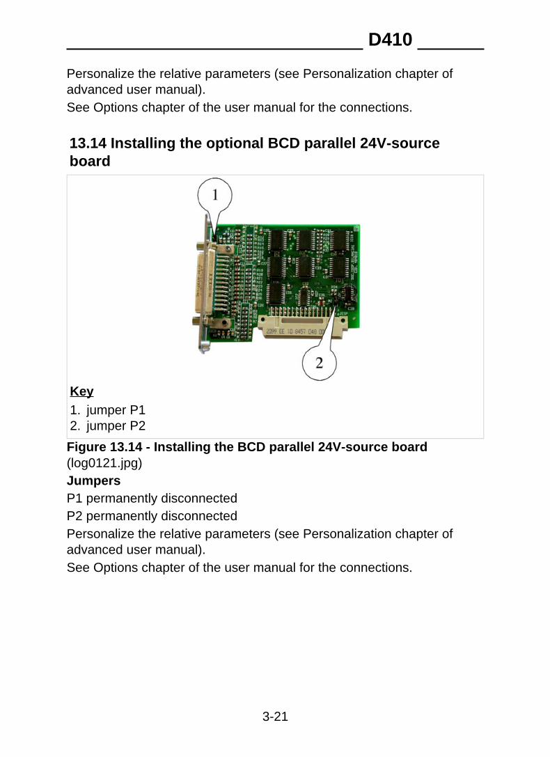
13.14 Installing the optional BCD parallel 24V-sourceboard
Key1. jumper P12. jumper P2
Figure 13.14 - Installing the BCD parallel 24V-source board(log0121.jpg)JumpersP1 permanently disconnectedP2 permanently disconnectedPersonalize the relative parameters (see Personalization chapter ofadvanced user manual).See Options chapter of the user manual for the connections.
D410
3-21

D410
3-22
14. PERSONALIZING METROLOGICALPARAMETERSThe terminal setup procedure can be accessed in two different ways.
✔ By pressing on power up (as explained in the Personalizationchapter of the advanced user manual) it is possible to accessnon-metrological parameters. In this way, the metrological parameterscan be displayed but not modified.✔ With the terminal switched on, after removing the seals, by pressingthe calibration button (see par. 14.1 on page 3-23 ) it is possible tomodify all the parameters, both metrological and non-metrological.
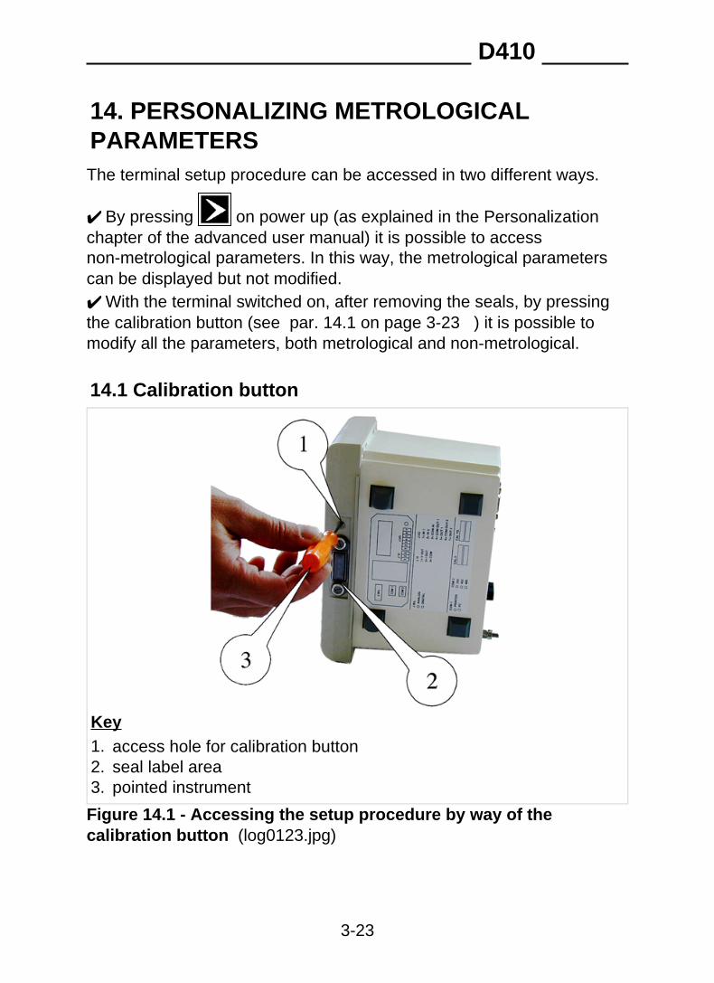
14.1 Calibration button
Key1. access hole for calibration button2. seal label area3. pointed instrument
Figure 14.1 - Accessing the setup procedure by way of thecalibration button (log0123.jpg)
D410
3-23
If you access the setup procedure by pressing the calibration button it ispossible to modify all the terminal parameters.The correct procedure is as follows:
✔ remove the seals from the terminal (lead or labels) (point 2 fig. 14.1on page 3-23 );
✔ switch on the terminal;✔ press the calibration button using a non-metallic pointed instrument
(point 3 fig. 14.1 on page 3-23 ) through the access hole (point 1 of fig. 14.1 on page 3-23 );
✔ select the menu display language; a few terminal identificationmessages will be displayed briefly (program code, version, serialnumber) immediately followed by the Setup menu.
On exiting Setup, the display language selected in the personalizationmenu will be restored.
WARNING Access to setup parameters by way of the calibration buttonis restricted to specialised personnel only.Any tampering by unauthorised personnel shall invalidate thewarranty with immediate effect.
The main metrological parameters are described in the followingparagraphs. For personalization of non-metrological parameters refer tothe Personalization chapter of the advanced user manual.
D410
3-24

14.2 Description of the main menus and metrologicalparametersUnless different indications are given, the description of the parametersillustrated in the following paragraphs is valid for both analogue anddigital scales.Consult par. 14.3 on page 3-41 for a description of the slave menusand parameters.
D410
3-25
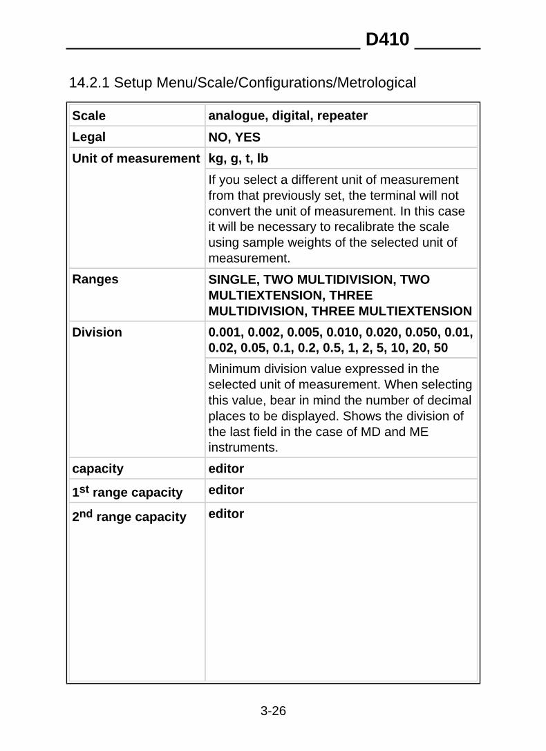
14.2.1 Setup Menu/Scale/Configurations/Metrological
analogue, digital, repeaterScale
Legal NO, YES
kg, g, t, lbUnit of measurement
If you select a different unit of measurementfrom that previously set, the terminal will notconvert the unit of measurement. In this caseit will be necessary to recalibrate the scaleusing sample weights of the selected unit ofmeasurement.
Ranges SINGLE, TWO MULTIDIVISION, TWOMULTIEXTENSION, THREEMULTIDIVISION, THREE MULTIEXTENSION
Division 0.001, 0.002, 0.005, 0.010, 0.020, 0.050, 0.01,0.02, 0.05, 0.1, 0.2, 0.5, 1, 2, 5, 10, 20, 50
Minimum division value expressed in theselected unit of measurement. When selectingthis value, bear in mind the number of decimalplaces to be displayed. Shows the division ofthe last field in the case of MD and MEinstruments.
editorcapacity
editor1st range capacity
editor2nd range capacity
D410
3-26
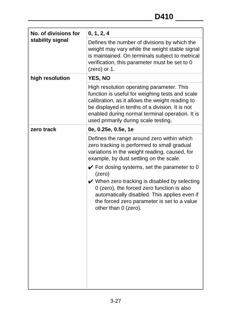
0, 1, 2, 4No. of divisions forstability signal Defines the number of divisions by which the
weight may vary while the weight stable signalis maintained. On terminals subject to metricalverification, this parameter must be set to 0(zero) or 1.
high resolution YES, NO
High resolution operating parameter. Thisfunction is useful for weighing tests and scalecalibration, as it allows the weight reading tobe displayed in tenths of a division. It is notenabled during normal terminal operation. It isused primarily during scale testing.
zero track 0e, 0.25e, 0.5e, 1e
Defines the range around zero within whichzero tracking is performed to small gradualvariations in the weight reading, caused, forexample, by dust settling on the scale.
✔ For dosing systems, set the parameter to 0(zero)
✔ When zero tracking is disabled by selecting0 (zero), the forced zero function is alsoautomatically disabled. This applies even ifthe forced zero parameter is set to a valueother than 0 (zero).
D410
3-27
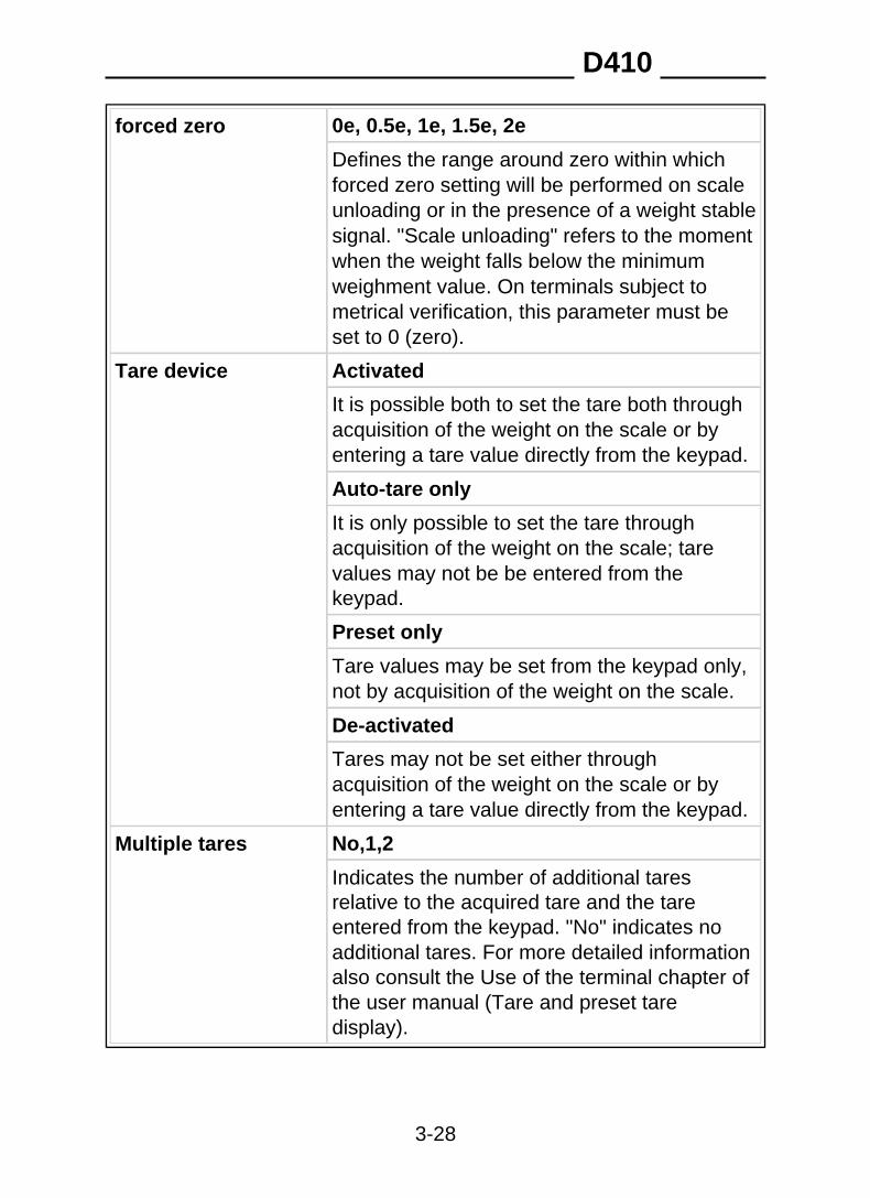
0e, 0.5e, 1e, 1.5e, 2eforced zero
Defines the range around zero within whichforced zero setting will be performed on scaleunloading or in the presence of a weight stablesignal. "Scale unloading" refers to the momentwhen the weight falls below the minimumweighment value. On terminals subject tometrical verification, this parameter must beset to 0 (zero).
Tare device Activated
It is possible both to set the tare both throughacquisition of the weight on the scale or byentering a tare value directly from the keypad.
Auto-tare only
It is only possible to set the tare throughacquisition of the weight on the scale; tarevalues may not be be entered from thekeypad.
Preset only
Tare values may be set from the keypad only,not by acquisition of the weight on the scale.
De-activated
Tares may not be set either throughacquisition of the weight on the scale or byentering a tare value directly from the keypad.
No,1,2Multiple tares
Indicates the number of additional taresrelative to the acquired tare and the tareentered from the keypad. "No" indicates noadditional tares. For more detailed informationalso consult the Use of the terminal chapter ofthe user manual (Tare and preset taredisplay).
D410
3-28
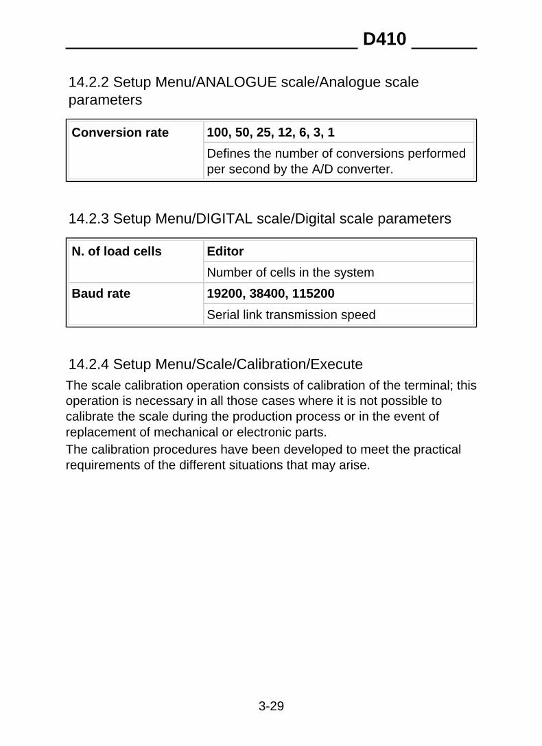
14.2.2 Setup Menu/ANALOGUE scale/Analogue scaleparameters
100, 50, 25, 12, 6, 3, 1Conversion rate
Defines the number of conversions performedper second by the A/D converter.
14.2.3 Setup Menu/DIGITAL scale/Digital scale parameters
EditorN. of load cells
Number of cells in the system
Baud rate 19200, 38400, 115200
Serial link transmission speed
14.2.4 Setup Menu/Scale/Calibration/ExecuteThe scale calibration operation consists of calibration of the terminal; thisoperation is necessary in all those cases where it is not possible tocalibrate the scale during the production process or in the event ofreplacement of mechanical or electronic parts.The calibration procedures have been developed to meet the practicalrequirements of the different situations that may arise.
D410
3-29
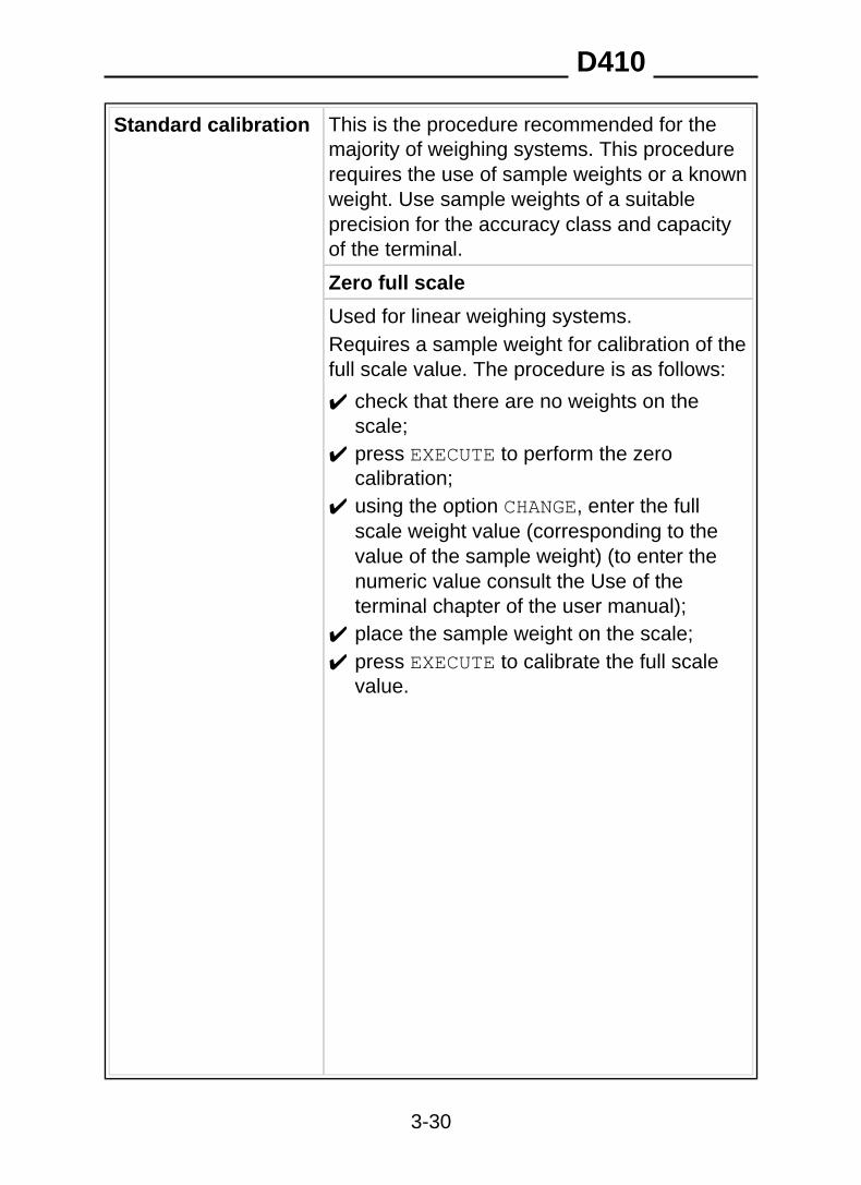
Standard calibration This is the procedure recommended for themajority of weighing systems. This procedurerequires the use of sample weights or a knownweight. Use sample weights of a suitableprecision for the accuracy class and capacityof the terminal.
Zero full scale
Used for linear weighing systems.Requires a sample weight for calibration of thefull scale value. The procedure is as follows:
✔ check that there are no weights on thescale;
✔ press EXECUTE to perform the zerocalibration;
✔ using the option CHANGE, enter the fullscale weight value (corresponding to thevalue of the sample weight) (to enter thenumeric value consult the Use of theterminal chapter of the user manual);
✔ place the sample weight on the scale;✔ press EXECUTE to calibrate the full scale
value.
D410
3-30
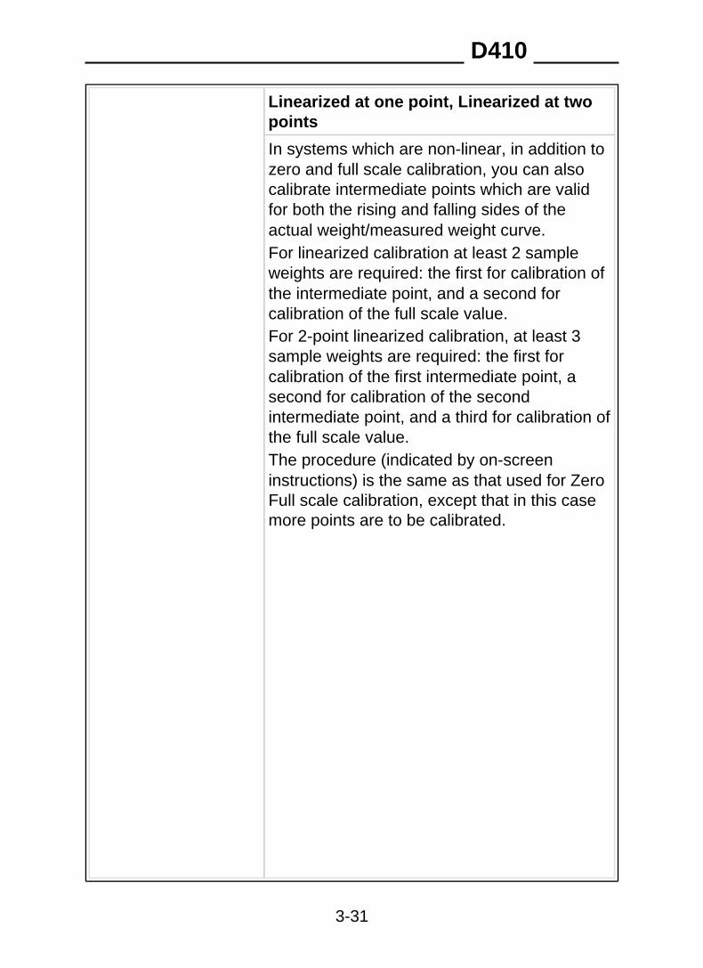
Linearized at one point, Linearized at twopoints
In systems which are non-linear, in addition tozero and full scale calibration, you can alsocalibrate intermediate points which are validfor both the rising and falling sides of theactual weight/measured weight curve.For linearized calibration at least 2 sampleweights are required: the first for calibration ofthe intermediate point, and a second forcalibration of the full scale value.For 2-point linearized calibration, at least 3sample weights are required: the first forcalibration of the first intermediate point, asecond for calibration of the secondintermediate point, and a third for calibration ofthe full scale value.The procedure (indicated by on-screeninstructions) is the same as that used for ZeroFull scale calibration, except that in this casemore points are to be calibrated.
D410
3-31
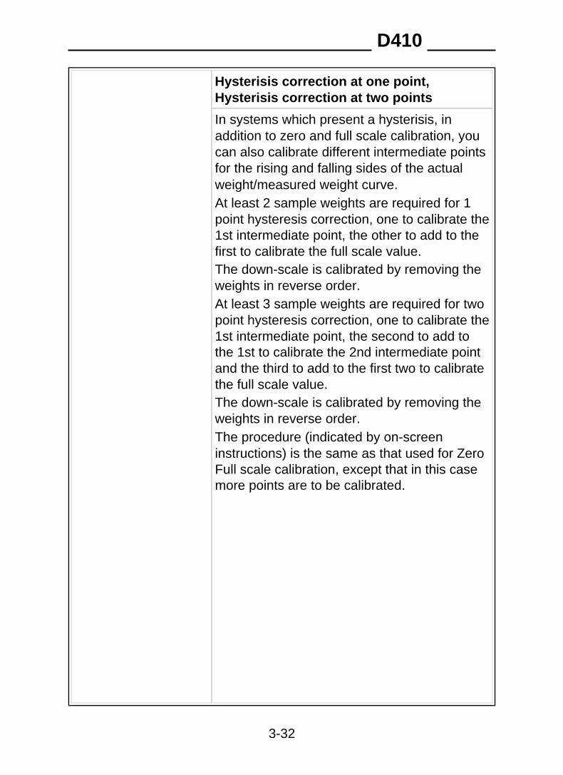
Hysterisis correction at one point,Hysterisis correction at two points
In systems which present a hysterisis, inaddition to zero and full scale calibration, youcan also calibrate different intermediate pointsfor the rising and falling sides of the actualweight/measured weight curve.At least 2 sample weights are required for 1point hysteresis correction, one to calibrate the1st intermediate point, the other to add to thefirst to calibrate the full scale value.The down-scale is calibrated by removing theweights in reverse order.At least 3 sample weights are required for twopoint hysteresis correction, one to calibrate the1st intermediate point, the second to add tothe 1st to calibrate the 2nd intermediate pointand the third to add to the first two to calibratethe full scale value.The down-scale is calibrated by removing theweights in reverse order.The procedure (indicated by on-screeninstructions) is the same as that used for ZeroFull scale calibration, except that in this casemore points are to be calibrated.
D410
3-32
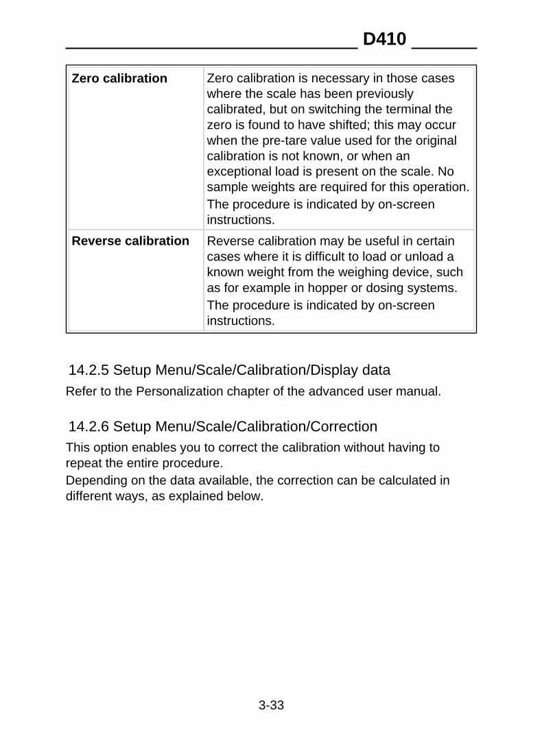
Zero calibration Zero calibration is necessary in those caseswhere the scale has been previouslycalibrated, but on switching the terminal thezero is found to have shifted; this may occurwhen the pre-tare value used for the originalcalibration is not known, or when anexceptional load is present on the scale. Nosample weights are required for this operation.The procedure is indicated by on-screeninstructions.
Reverse calibration Reverse calibration may be useful in certaincases where it is difficult to load or unload aknown weight from the weighing device, suchas for example in hopper or dosing systems.The procedure is indicated by on-screeninstructions.
14.2.5 Setup Menu/Scale/Calibration/Display dataRefer to the Personalization chapter of the advanced user manual.
14.2.6 Setup Menu/Scale/Calibration/CorrectionThis option enables you to correct the calibration without having torepeat the entire procedure.Depending on the data available, the correction can be calculated indifferent ways, as explained below.
D410
3-33
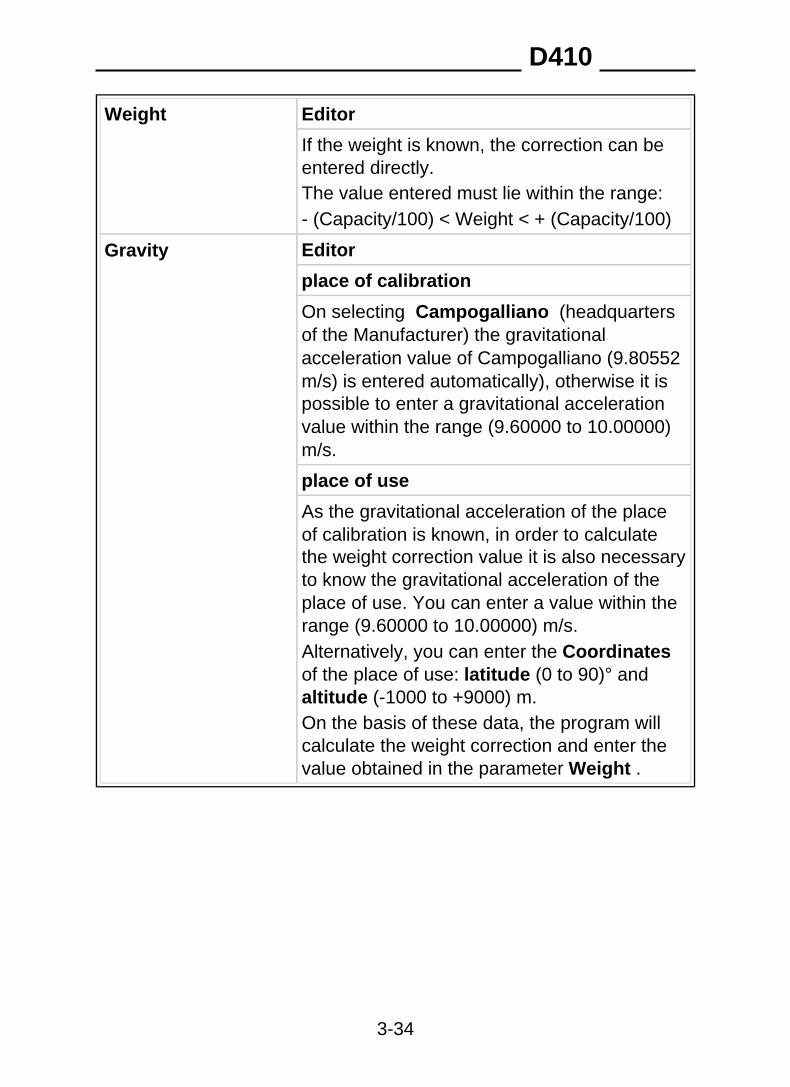
EditorWeight
If the weight is known, the correction can beentered directly.The value entered must lie within the range:- (Capacity/100) < Weight < + (Capacity/100)
EditorGravity
place of calibration
On selecting Campogalliano (headquartersof the Manufacturer) the gravitationalacceleration value of Campogalliano (9.80552m/s) is entered automatically), otherwise it ispossible to enter a gravitational accelerationvalue within the range (9.60000 to 10.00000)m/s.
place of use
As the gravitational acceleration of the placeof calibration is known, in order to calculatethe weight correction value it is also necessaryto know the gravitational acceleration of theplace of use. You can enter a value within therange (9.60000 to 10.00000) m/s.Alternatively, you can enter the Coordinatesof the place of use: latitude (0 to 90)° andaltitude (-1000 to +9000) m.On the basis of these data, the program willcalculate the weight correction and enter thevalue obtained in the parameter Weight .
D410
3-34

14.2.7 Setup Menu/DIGITAL scale/Calibration/Angle calibr.Angle calibration is used to correct digital cell assembly errors,constructional tolerances, etc.To carry out the angle calibration operation, the sample weight (notnecessarily known) must be loaded in sequence into each digital cell.
D410
3-35
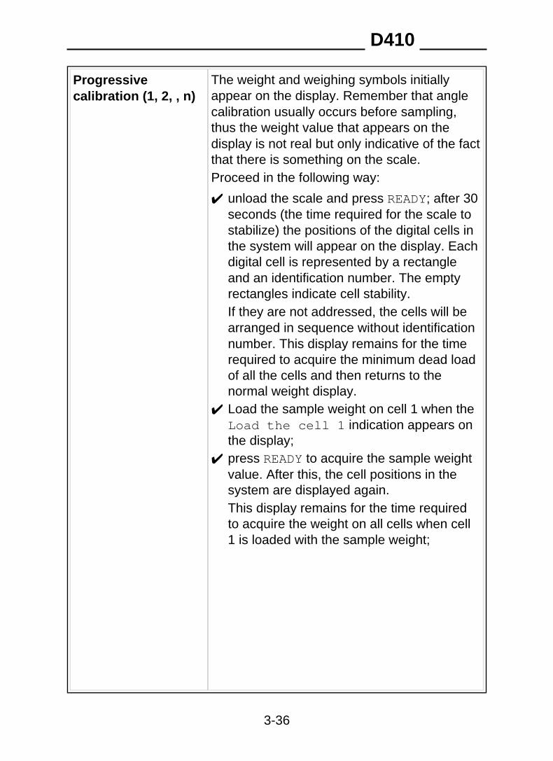
Progressivecalibration (1, 2, , n)
The weight and weighing symbols initiallyappear on the display. Remember that anglecalibration usually occurs before sampling,thus the weight value that appears on thedisplay is not real but only indicative of the factthat there is something on the scale.Proceed in the following way:
unload the scale and press READY; after 30seconds (the time required for the scale tostabilize) the positions of the digital cells inthe system will appear on the display. Eachdigital cell is represented by a rectangleand an identification number. The emptyrectangles indicate cell stability.
✔
If they are not addressed, the cells will bearranged in sequence without identificationnumber. This display remains for the timerequired to acquire the minimum dead loadof all the cells and then returns to thenormal weight display.
✔ Load the sample weight on cell 1 when theLoad the cell 1 indication appears onthe display;press READY to acquire the sample weightvalue. After this, the cell positions in thesystem are displayed again.This display remains for the time requiredto acquire the weight on all cells when cell1 is loaded with the sample weight;
✔
D410
3-36
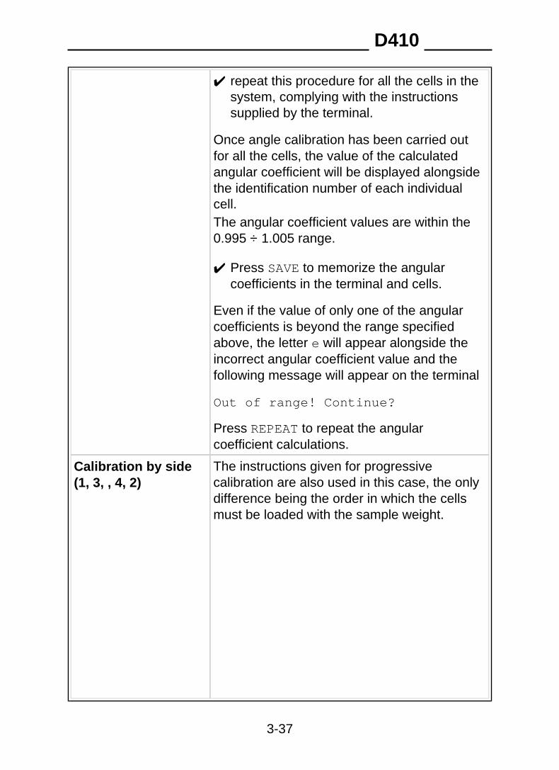
✔ repeat this procedure for all the cells in thesystem, complying with the instructionssupplied by the terminal.
Once angle calibration has been carried outfor all the cells, the value of the calculatedangular coefficient will be displayed alongsidethe identification number of each individualcell.The angular coefficient values are within the0.995 ÷ 1.005 range.
✔ Press SAVE to memorize the angularcoefficients in the terminal and cells.
Even if the value of only one of the angularcoefficients is beyond the range specifiedabove, the letter e will appear alongside theincorrect angular coefficient value and thefollowing message will appear on the terminal
Out of range! Continue?
Press REPEAT to repeat the angularcoefficient calculations.
The instructions given for progressivecalibration are also used in this case, the onlydifference being the order in which the cellsmust be loaded with the sample weight.
Calibration by side(1, 3, , 4, 2)
D410
3-37
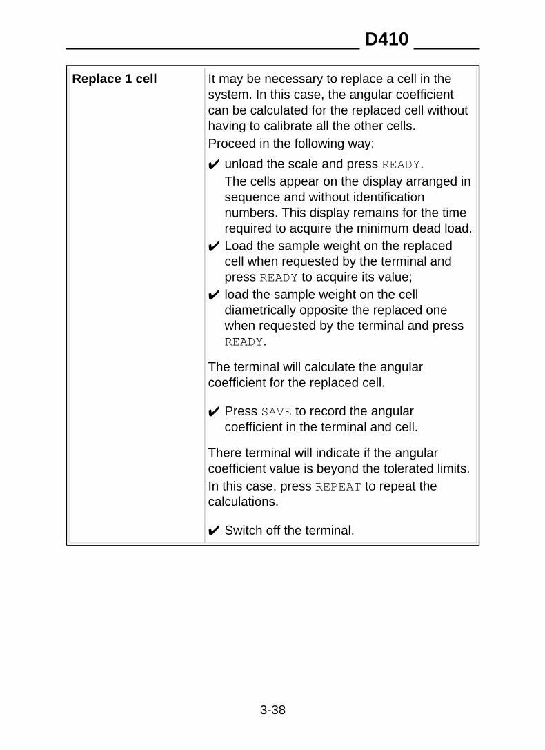
Replace 1 cell It may be necessary to replace a cell in thesystem. In this case, the angular coefficientcan be calculated for the replaced cell withouthaving to calibrate all the other cells.Proceed in the following way:
unload the scale and press READY.✔
The cells appear on the display arranged insequence and without identificationnumbers. This display remains for the timerequired to acquire the minimum dead load.
✔ Load the sample weight on the replacedcell when requested by the terminal andpress READY to acquire its value;
✔ load the sample weight on the celldiametrically opposite the replaced onewhen requested by the terminal and pressREADY.
The terminal will calculate the angularcoefficient for the replaced cell.
✔ Press SAVE to record the angularcoefficient in the terminal and cell.
There terminal will indicate if the angularcoefficient value is beyond the tolerated limits.In this case, press REPEAT to repeat thecalculations.
✔ Switch off the terminal.
D410
3-38
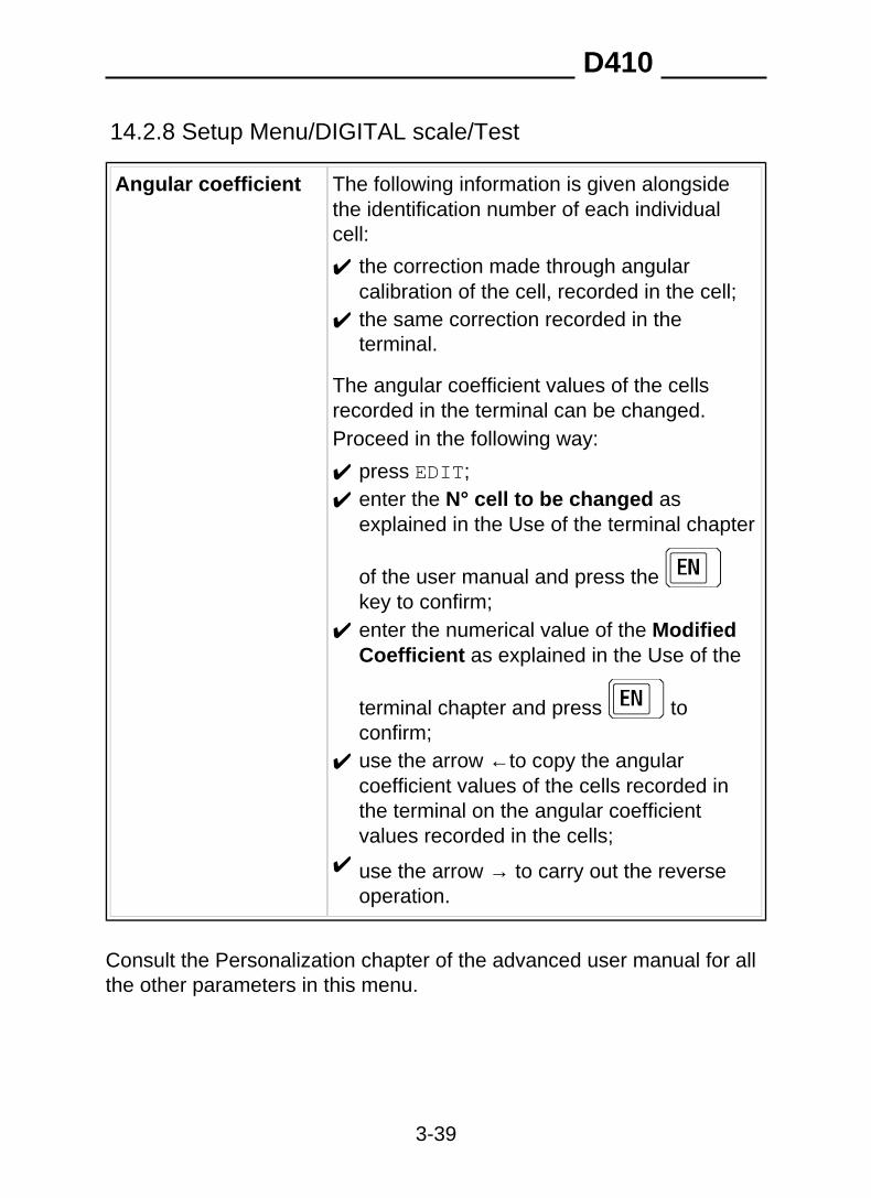
14.2.8 Setup Menu/DIGITAL scale/Test
Angular coefficient The following information is given alongsidethe identification number of each individualcell:
✔ the correction made through angularcalibration of the cell, recorded in the cell;
✔ the same correction recorded in theterminal.
The angular coefficient values of the cellsrecorded in the terminal can be changed.Proceed in the following way:
✔ press EDIT;✔ enter the N° cell to be changed as
explained in the Use of the terminal chapter
of the user manual and press the key to confirm;
✔ enter the numerical value of the ModifiedCoefficient as explained in the Use of the
terminal chapter and press toconfirm;
✔ use the arrow ← to copy the angularcoefficient values of the cells recorded inthe terminal on the angular coefficientvalues recorded in the cells;
✔ use the arrow → to carry out the reverseoperation.
Consult the Personalization chapter of the advanced user manual for allthe other parameters in this menu.
D410
3-39
14.2.9 Setup Menu/DIGITAL scale/Test/Terminal data storageImportant information for the operation of the terminal are recorded onthe terminal board. This information includes the sampling data, theangular coefficients, the serial numbers and the cell addresses, etc.These data can also be saved in the cells by means of the Terminaldata storage item.
14.2.10 Setup Menu/DIGITAL scale/Test/Terminal datareinstatementThe cell data (sampling, serial numbers, angular coefficients, addresses)can be loaded into the terminal.
D410
3-40
14.3 Repeater scale
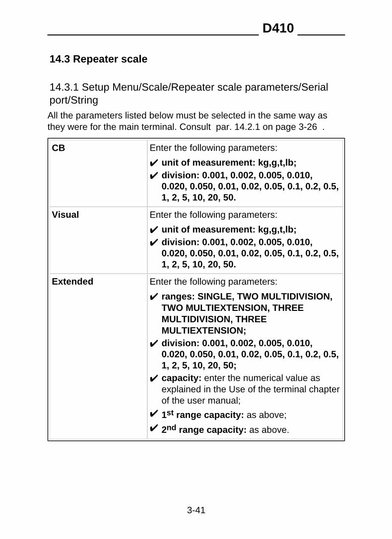
14.3.1 Setup Menu/Scale/Repeater scale parameters/Serialport/StringAll the parameters listed below must be selected in the same way asthey were for the main terminal. Consult par. 14.2.1 on page 3-26 .
Enter the following parameters:CB
✔ unit of measurement: kg,g,t,lb;✔ division: 0.001, 0.002, 0.005, 0.010,
0.020, 0.050, 0.01, 0.02, 0.05, 0.1, 0.2, 0.5,1, 2, 5, 10, 20, 50.
Enter the following parameters:Visual
✔ unit of measurement: kg,g,t,lb;✔ division: 0.001, 0.002, 0.005, 0.010,
0.020, 0.050, 0.01, 0.02, 0.05, 0.1, 0.2, 0.5,1, 2, 5, 10, 20, 50.
Enter the following parameters:Extended
✔ ranges: SINGLE, TWO MULTIDIVISION,TWO MULTIEXTENSION, THREEMULTIDIVISION, THREEMULTIEXTENSION;
✔ division: 0.001, 0.002, 0.005, 0.010,0.020, 0.050, 0.01, 0.02, 0.05, 0.1, 0.2, 0.5,1, 2, 5, 10, 20, 50;
✔ capacity: enter the numerical value asexplained in the Use of the terminal chapterof the user manual;
✔ 1st range capacity: as above;✔ 2nd range capacity: as above.
D410
3-41
Consult the Personalization chapter of the advanced user manual for theother parameters in this menu.Refer to chapters 15 and 16 of this section for maintenance andsoftware updates.
D410
3-42
15. SOFTWARE UPGRADE
15.1 Setup Menu/UpgradeYou can:
✔ update the program version;✔ update the program.
In the first case, all the parameters including sampling and the archives,remain unchanged.In the second case, the parameters, metrological data, any prints,transmissions and personalized messages do not change. However,remember that if the new program involves substantial changes to theoperating mode or further parameters, the old configuration could bewrongly interpreted. This is why it is advisable to print the report beforeand after the update in order to make sure that the parameters arecorrect.The data in archives common to both programs remain unchanged.The logo of the terminal can be loaded and cancelled via Dialogic. It isnot changed by initialization or by an update.
CAUTION If the CPU board is replaced it may also be necessary toupdate the software on the new board so that it matches thatof the old board.Make sure that the installed software and board arecompatible with each other.Do not interrupt the updating procedure as this could impairthe result of the downloading operation.More detailed information is available on request from theManufacturer.
D410
3-43
There are two possible methods for upgrading the firmware, which aredescribed in the following paragraphs ( par. 15.1.1 on page 3-44 and par. 15.1.2 on page 3-46 ).
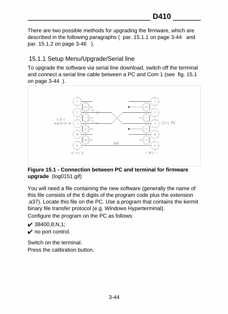
15.1.1 Setup Menu/Upgrade/Serial lineTo upgrade the software via serial line download, switch off the terminaland connect a serial line cable between a PC and Com 1 (see fig. 15.1on page 3-44 ).
Figure 15.1 - Connection between PC and terminal for firmwareupgrade (log0151.gif)
You will need a file containing the new software (generally the name ofthis file consists of the 6 digits of the program code plus the extension.a37). Locate this file on the PC. Use a program that contains the kermitbinary file transfer protocol (e.g. Windows Hyperterminal).Configure the program on the PC as follows:
✔ 38400,8,N,1;✔ no port control.
Switch on the terminal.Press the calibration button.
D410
3-44
Follow the menu path:
Italian>Upgrade>Serial line>Software upgrade viaserial line... CAUTION: the program will be deleted;have upgrade ready.
CONTINUE?> YES
Premendo il tasto selezionare kermit protocol.The terminal launches a new program (boot program) that allows you toinstall the new firmware.The terminal will give the following instructions:
Connect com01 to host, select kermit protocol, 38400,8, N, 1 (Connect host with Kermit protocol to com1, configuration38400, 8, N, 1)
The terminal will set on hold and give the .waiting message,cancelling the program it contains..Transmit the file with the new software version from the PC by means ofthe Kermit procedure.On receiving the file, the terminal displays the message .loading.On completion of the transfer procedure the terminal displays.correctly terminated: switch off. (transfer completedsuccessfully; switch off the terminal).Should any error messages be displayed notify Assistance Service.Switch the terminal off and then on again before using the new software.
D410
3-45
15.1.2 Upgrade via upgrade boardThe firmware is upgraded by installing an upgrade board. Proceed in thefollowing way:
✔ switch off the terminal;✔ disconnect all cables connected to the terminal;✔ open the casing as shown in par. 13.1 on page 3-7 ;✔ remove the jumper P1 on the CPU board (point 1 fig. 15.2 on page
3-47 );✔ insert the upgrade card as shown in fig. 15.3 on page 3-48 ;✔ switch on the terminal;
CAUTION This operation exposes some parts of the internal circuitry.Be careful not to cause accidental short-circuits!
The terminal detects the presence of program on the upgrade board anddisplays the message .Upgrade software from board . The codeof the program to be installed is also displayed.The subsequent messages indicate the successful deletion of the oldprogram, the loading and testing of the new program.Should any error messages be displayed notify Assistance Service.
✔ Switch off the terminal;✔ remove the upgrade board;✔ replace the jumper P1 on the CPU board.
D410
3-46

Key1. Jumper P12. Connectors for upgrade board
Figure 15.2 - CPU board (log0152.gif)
D410
3-47
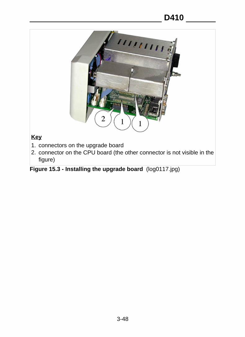
Key1. connectors on the upgrade board2. connector on the CPU board (the other connector is not visible in the
figure)
Figure 15.3 - Installing the upgrade board (log0117.jpg)
D410
3-48
16. MAINTENANCE
16.1 Setup Menu/Maintenance
WARNING Accessing these menu options could delete all the data inthe terminal memory!
D410
3-49
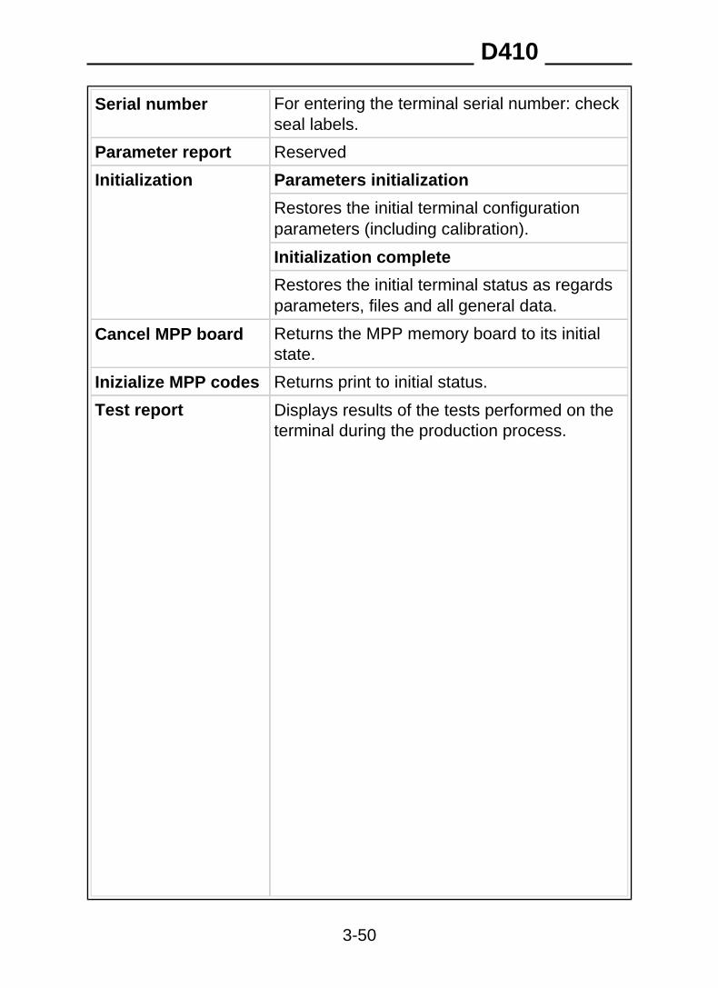
Serial number For entering the terminal serial number: checkseal labels.
Parameter report Reserved
Initialization Parameters initialization
Restores the initial terminal configurationparameters (including calibration).
Initialization complete
Restores the initial terminal status as regardsparameters, files and all general data.
Cancel MPP board Returns the MPP memory board to its initialstate.
Returns print to initial status.Inizialize MPP codes
Displays results of the tests performed on theterminal during the production process.
Test report
D410
3-50
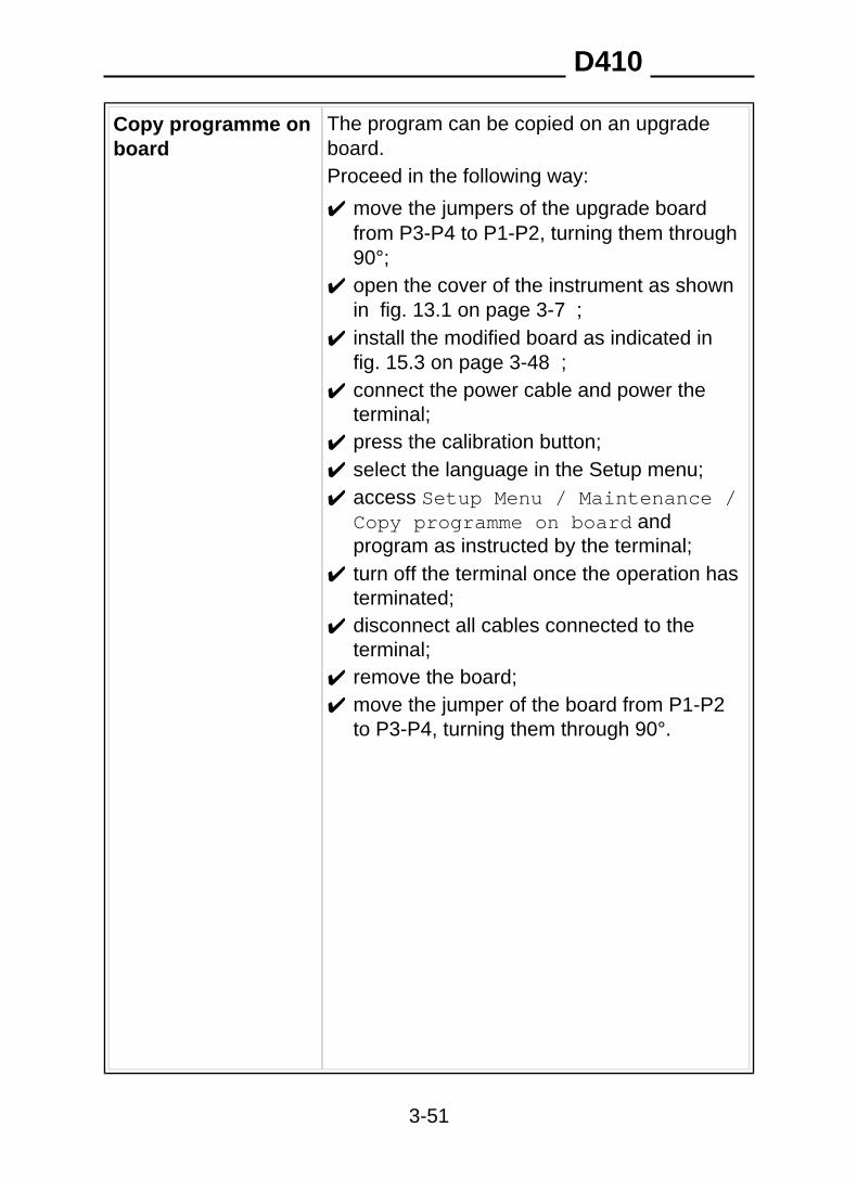
The program can be copied on an upgradeboard.
Copy programme onboard
Proceed in the following way:
✔ move the jumpers of the upgrade boardfrom P3-P4 to P1-P2, turning them through90°;
✔ open the cover of the instrument as shownin fig. 13.1 on page 3-7 ;
✔ install the modified board as indicated in fig. 15.3 on page 3-48 ;
✔ connect the power cable and power theterminal;
✔ press the calibration button;✔ select the language in the Setup menu;✔ access Setup Menu / Maintenance /
Copy programme on board andprogram as instructed by the terminal;
✔ turn off the terminal once the operation hasterminated;
✔ disconnect all cables connected to theterminal;
✔ remove the board;✔ move the jumper of the board from P1-P2
to P3-P4, turning them through 90°.
D410
3-51
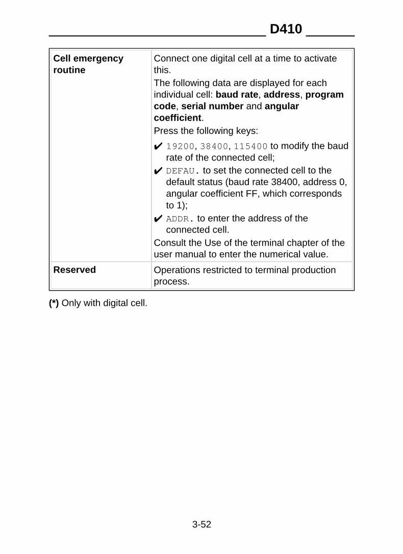
Connect one digital cell at a time to activatethis.
Cell emergencyroutine
The following data are displayed for eachindividual cell: baud rate, address, programcode, serial number and angularcoefficient.Press the following keys:
✔ 19200, 38400, 115400 to modify the baudrate of the connected cell;
✔ DEFAU. to set the connected cell to thedefault status (baud rate 38400, address 0,angular coefficient FF, which correspondsto 1);
✔ ADDR. to enter the address of theconnected cell.
Consult the Use of the terminal chapter of theuser manual to enter the numerical value.
Reserved Operations restricted to terminal productionprocess.
(*) Only with digital cell.
D410
3-52

17. TROUBLESHOOTINGThis chapter contains descriptions of the error messages that may bedisplayed on the terminal along with possible remedies. See alsochapter Troubleshooting of the user manual.
D410
3-53
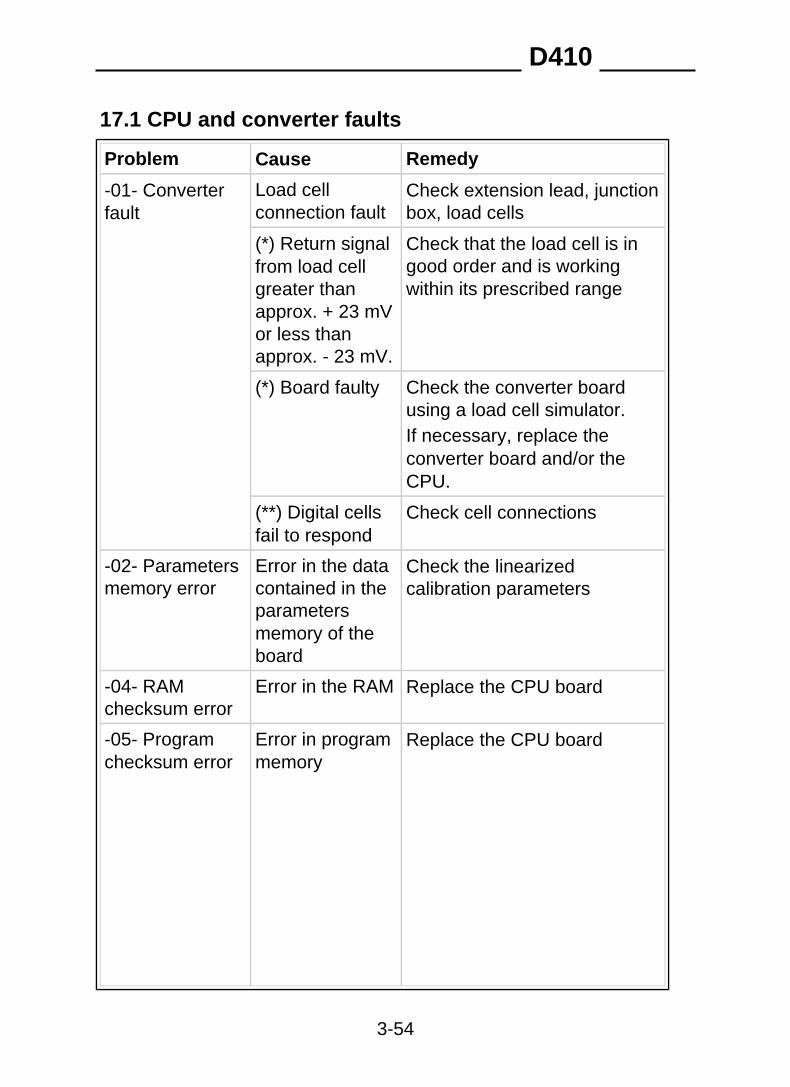
17.1 CPU and converter faults
Problem Cause Remedy
Load cellconnection fault
Check extension lead, junctionbox, load cells
-01- Converterfault
Check that the load cell is ingood order and is workingwithin its prescribed range
(*) Return signalfrom load cellgreater thanapprox. + 23 mVor less thanapprox. - 23 mV.
(*) Board faulty Check the converter boardusing a load cell simulator.If necessary, replace theconverter board and/or theCPU.
Check cell connections(**) Digital cellsfail to respond
Check the linearizedcalibration parameters
-02- Parametersmemory error
Error in the datacontained in theparametersmemory of theboard
Error in the RAM Replace the CPU board-04- RAMchecksum error
Replace the CPU board-05- Programchecksum error
Error in programmemory
D410
3-54
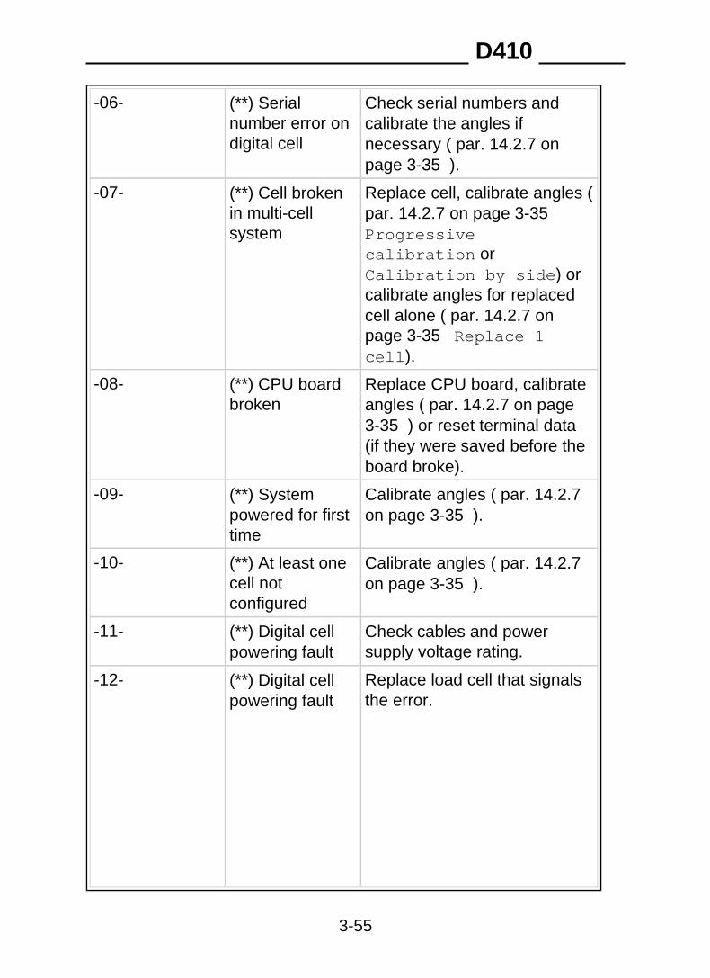
-06- (**) Serialnumber error ondigital cell
Check serial numbers andcalibrate the angles ifnecessary ( par. 14.2.7 onpage 3-35 ).
-07- (**) Cell brokenin multi-cellsystem
Replace cell, calibrate angles (par. 14.2.7 on page 3-35 Progressivecalibration orCalibration by side) orcalibrate angles for replacedcell alone ( par. 14.2.7 onpage 3-35 Replace 1cell).
-08- (**) CPU boardbroken
Replace CPU board, calibrateangles ( par. 14.2.7 on page3-35 ) or reset terminal data(if they were saved before theboard broke).
-09- Calibrate angles ( par. 14.2.7on page 3-35 ).
(**) Systempowered for firsttime
-10- Calibrate angles ( par. 14.2.7on page 3-35 ).
(**) At least onecell notconfigured
Check cables and powersupply voltage rating.
-11- (**) Digital cellpowering fault
Replace load cell that signalsthe error.
-12- (**) Digital cellpowering fault
D410
3-55
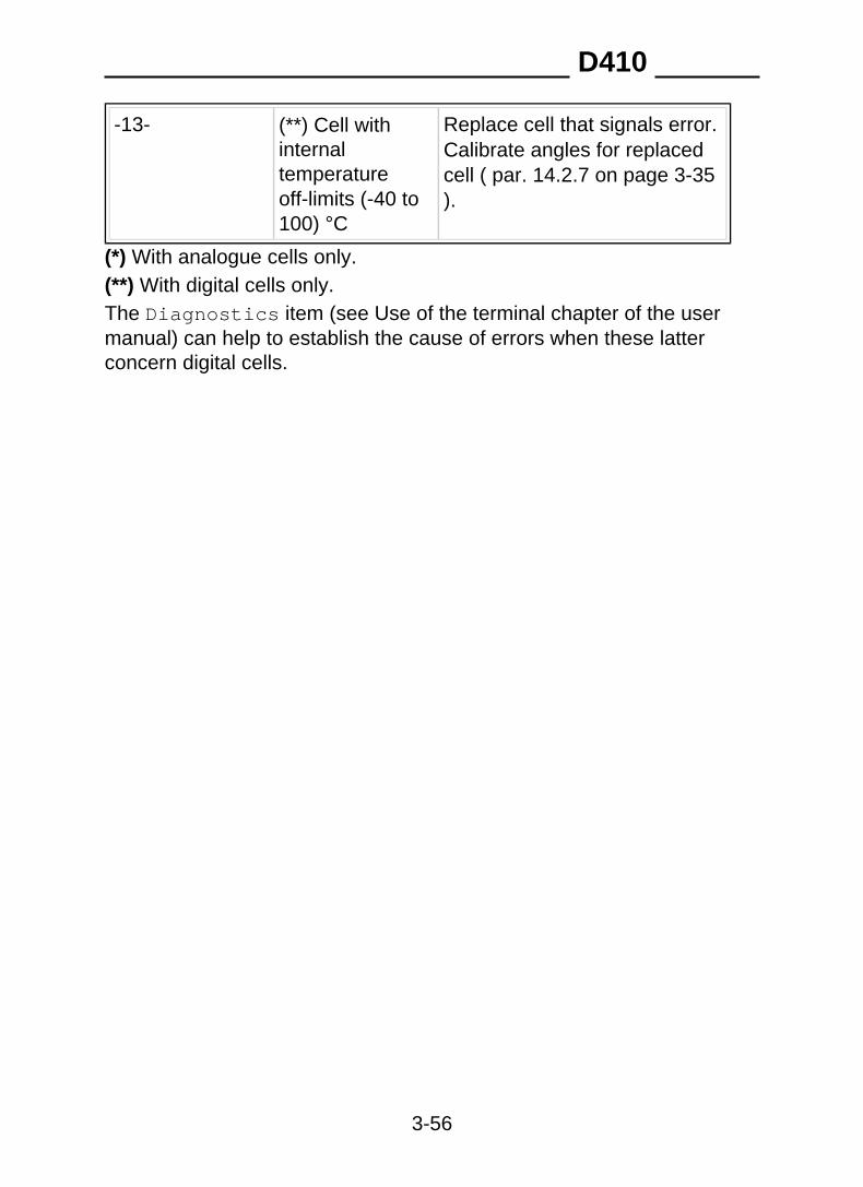
-13- Replace cell that signals error.Calibrate angles for replacedcell ( par. 14.2.7 on page 3-35).
(**) Cell withinternaltemperatureoff-limits (-40 to100) °C
(*) With analogue cells only.(**) With digital cells only.The Diagnostics item (see Use of the terminal chapter of the usermanual) can help to establish the cause of errors when these latterconcern digital cells.
D410
3-56
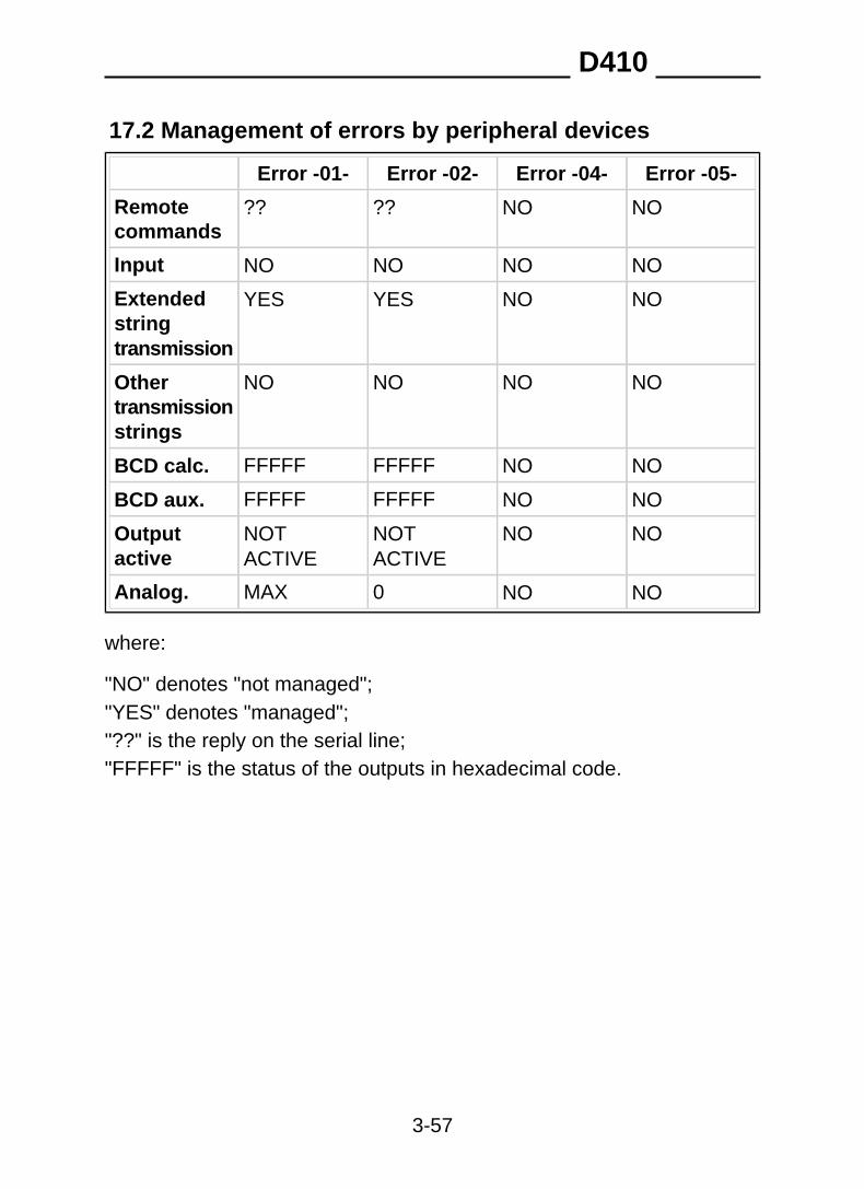
17.2 Management of errors by peripheral devices
Error -04-Error -01- Error -02- Error -05-
?? ?? NO NORemotecommands
NOInput NO NO NO
NOYES YES NOExtendedstringtransmission
NONO NO NOOthertransmissionstrings
BCD calc. FFFFF FFFFF NO NO
BCD aux. FFFFF FFFFF NO NO
NOTACTIVE
NO NOOutputactive
NOTACTIVE
Analog. MAX 0 NO NO
where:
"NO" denotes "not managed";"YES" denotes "managed";"??" is the reply on the serial line;"FFFFF" is the status of the outputs in hexadecimal code.
D410
3-57


SOCIETÀ COOPERATIVA
BILANCIAI
SOC. COOP. BILANCIAI CAMPOGALLIANO A.R.L.41011 Campogalliano (MO) Via Ferrari, 16
tel. +39 (0)59 893 611 - fax +39 (0)59 527 079home page: http://www.coopbilanciai.it
E-mail: [email protected]
service apres-venteservizio post-vendita after sales serviceKundendienstservice servicio post-venta serviço pós-venda
tel. +39 (0)59 893 612 - fax +39 (0)59 527 294