Embed Size (px)
Citation preview
HERRENKNECHT AG
SOFTGROUND TBMS
> 40 FT
Reference Papers:- The making of the Mixshield. - Lifting the lid on Mixshield performance. - The latest technology in mechanized tunneling –
the design of the world’s largest EPB and slurry shield TBMs.
Project No. Project name Shield diameter [m]
S - 108 Elbtunnel Hamburg, Germany 14.20
S - 164 Lefortovo Moscow, Russia 14.20
S - 250 Silberwald Moscow, Russia 14.20
S - 252 Kuala Lumpur, Malaysia 13.21
S - 253 Kuala Lumpur, Malaysia 13.21
S - 300 M-30 Madrid, Spain 15.20
S - 317 Shanghai, China 15.43
S - 318 Shanghai, China 15.43
S - 349 Nanjing, China 14.93
S - 350 Nanjing, China 14.93
S - 352 Münster Wiesing, Austria 13.00
S - 381 H8 Jenbach, Austria 13.00
S - 483 Moscow, Russia 14.20
S - 534 Sochi, Russia 13.21
Pre-Design Moscow, Russia 19.00
1
HERRENKNECHT | TRAFFIC TUNNELLING SALES.NET
PROJECT DATASHEET. Updated: 5/15/2008
S-Number:Name:Location:Country:
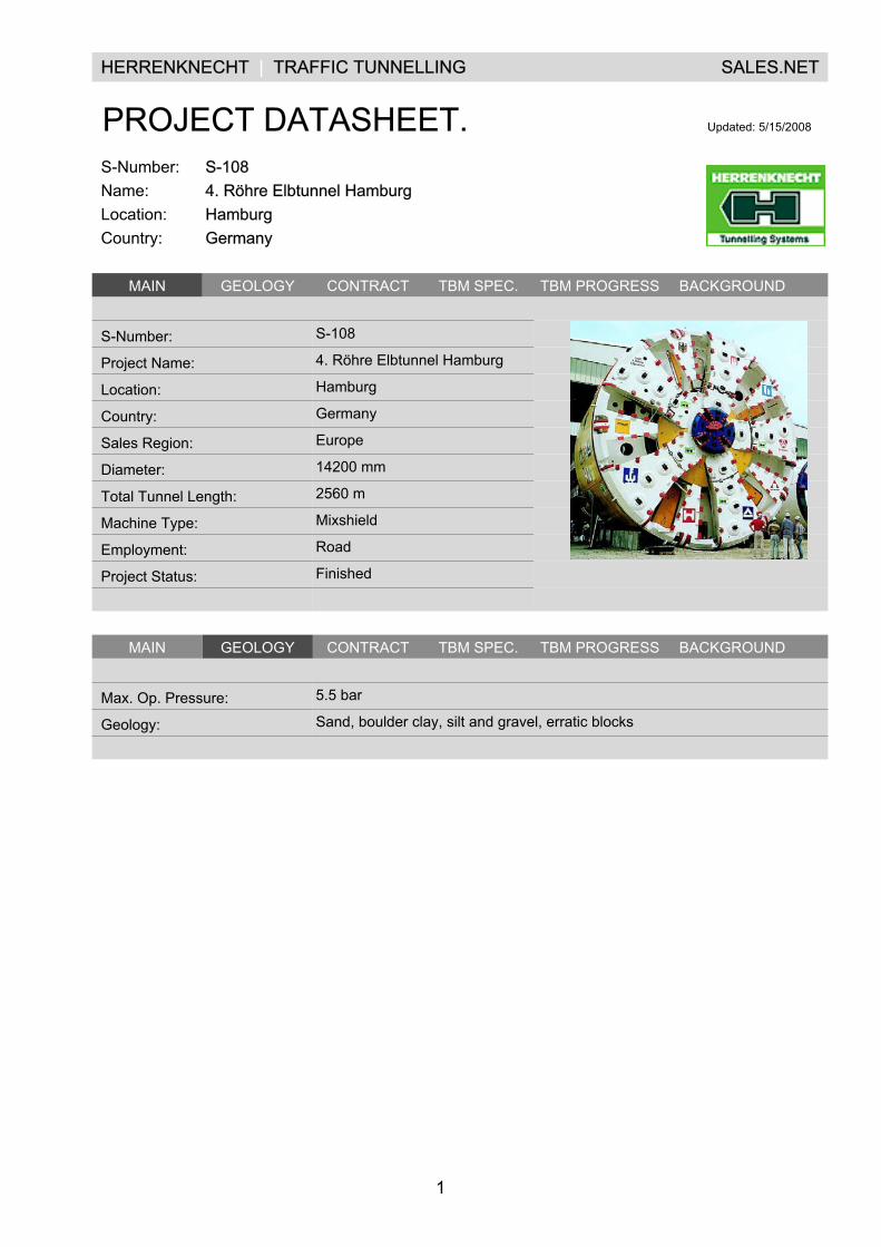
S-1084. Röhre Elbtunnel HamburgHamburgGermany
.MAIN GEOLOGY CONTRACT TBM SPEC. TBM PROGRESS BACKGROUND .
.
S-Number: S-108 .
Project Name: 4. Röhre Elbtunnel Hamburg .
Location: Hamburg .
Country: Germany .
Sales Region: Europe .
Diameter: 14200 mm .
Total Tunnel Length: 2560 m .
Machine Type: Mixshield .
Employment: Road .
Project Status: Finished .
. . .
.MAIN GEOLOGY CONTRACT TBM SPEC. TBM PROGRESS BACKGROUND .
.
Max. Op. Pressure: 5.5 bar
Geology: Sand, boulder clay, silt and gravel, erratic blocks
.
.
1
HERRENKNECHT | TRAFFIC TUNNELLING SALES.NET
PROJECT DATASHEET. Updated: 5/15/2008
S-Number:Name:Location:Country:
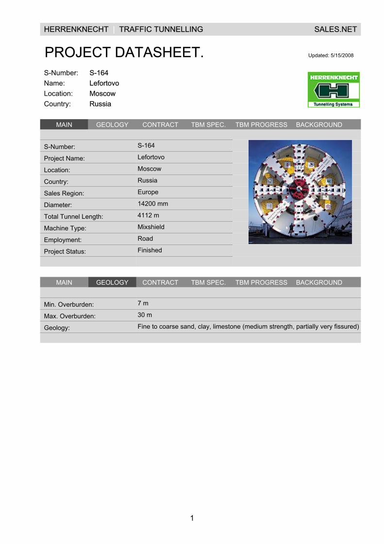
S-164LefortovoMoscowRussia
.MAIN GEOLOGY CONTRACT TBM SPEC. TBM PROGRESS BACKGROUND .
.
S-Number: S-164 .
Project Name: Lefortovo .
Location: Moscow .
Country: Russia .
Sales Region: Europe .
Diameter: 14200 mm .
Total Tunnel Length: 4112 m .
Machine Type: Mixshield .
Employment: Road .
Project Status: Finished .
. . .
.MAIN GEOLOGY CONTRACT TBM SPEC. TBM PROGRESS BACKGROUND .
.
Min. Overburden: 7 m
Max. Overburden: 30 m
Geology: Fine to coarse sand, clay, limestone (medium strength, partially very fissured)
.
.
1
HERRENKNECHT | TRAFFIC TUNNELLING SALES.NET
PROJECT DATASHEET. Updated: 5/15/2008
S-Number:Name:Location:Country:
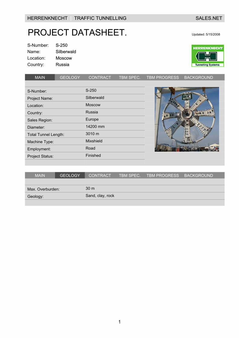
S-250SilberwaldMoscowRussia
.MAIN GEOLOGY CONTRACT TBM SPEC. TBM PROGRESS BACKGROUND .
.
S-Number: S-250 .
Project Name: Silberwald .
Location: Moscow .
Country: Russia .
Sales Region: Europe .
Diameter: 14200 mm .
Total Tunnel Length: 3010 m .
Machine Type: Mixshield .
Employment: Road .
Project Status: Finished .
. . .
.MAIN GEOLOGY CONTRACT TBM SPEC. TBM PROGRESS BACKGROUND .
.
Max. Overburden: 30 m
Geology: Sand, clay, rock
.
.
1
HERRENKNECHT | TRAFFIC TUNNELLING SALES.NET
PROJECT DATASHEET. Updated: 11/12/2008
S-Number:Name:Location:Country:
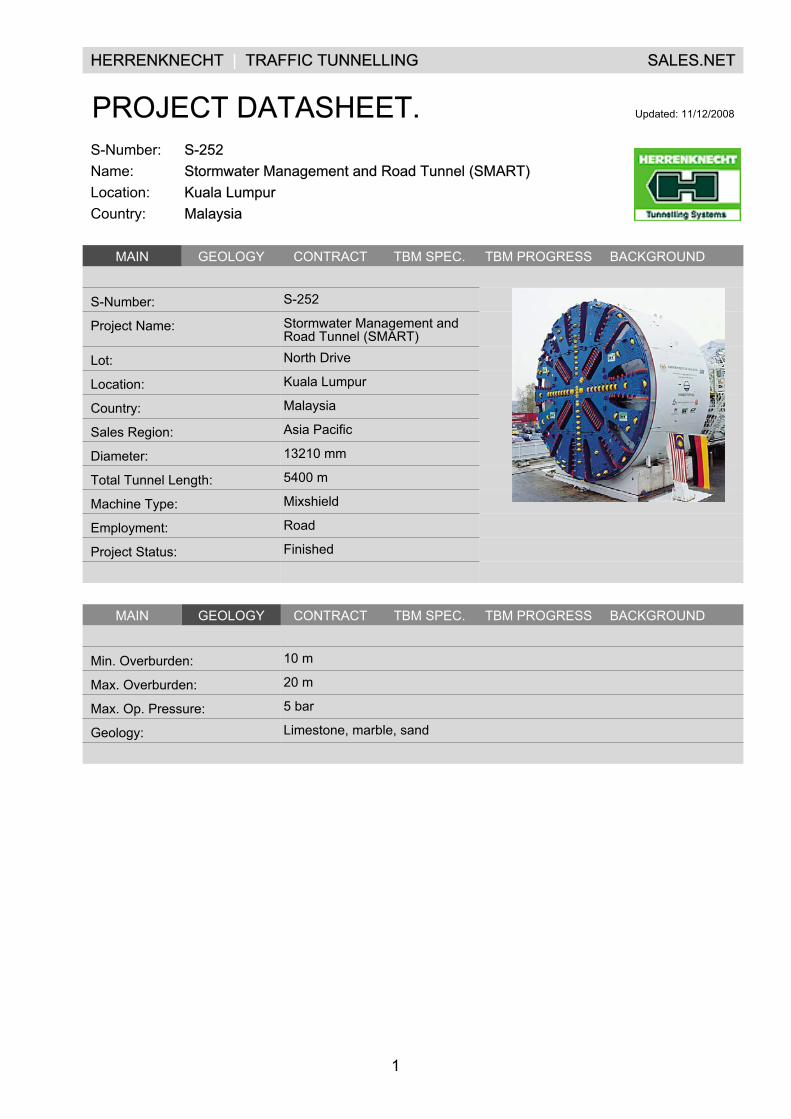
S-252Stormwater Management and Road Tunnel (SMART)Kuala LumpurMalaysia
.MAIN GEOLOGY CONTRACT TBM SPEC. TBM PROGRESS BACKGROUND .
.
S-Number: S-252 .
Project Name: Stormwater Management andRoad Tunnel (SMART)
.
Lot: North Drive .
Location: Kuala Lumpur .
Country: Malaysia .
Sales Region: Asia Pacific .
Diameter: 13210 mm .
Total Tunnel Length: 5400 m .
Machine Type: Mixshield .
Employment: Road .
Project Status: Finished .
. . .
.MAIN GEOLOGY CONTRACT TBM SPEC. TBM PROGRESS BACKGROUND .
.
Min. Overburden: 10 m
Max. Overburden: 20 m
Max. Op. Pressure: 5 bar
Geology: Limestone, marble, sand
.
.
1
HERRENKNECHT | TRAFFIC TUNNELLING SALES.NET
PROJECT DATASHEET. Updated: 11/14/2008
S-Number:Name:Location:Country:
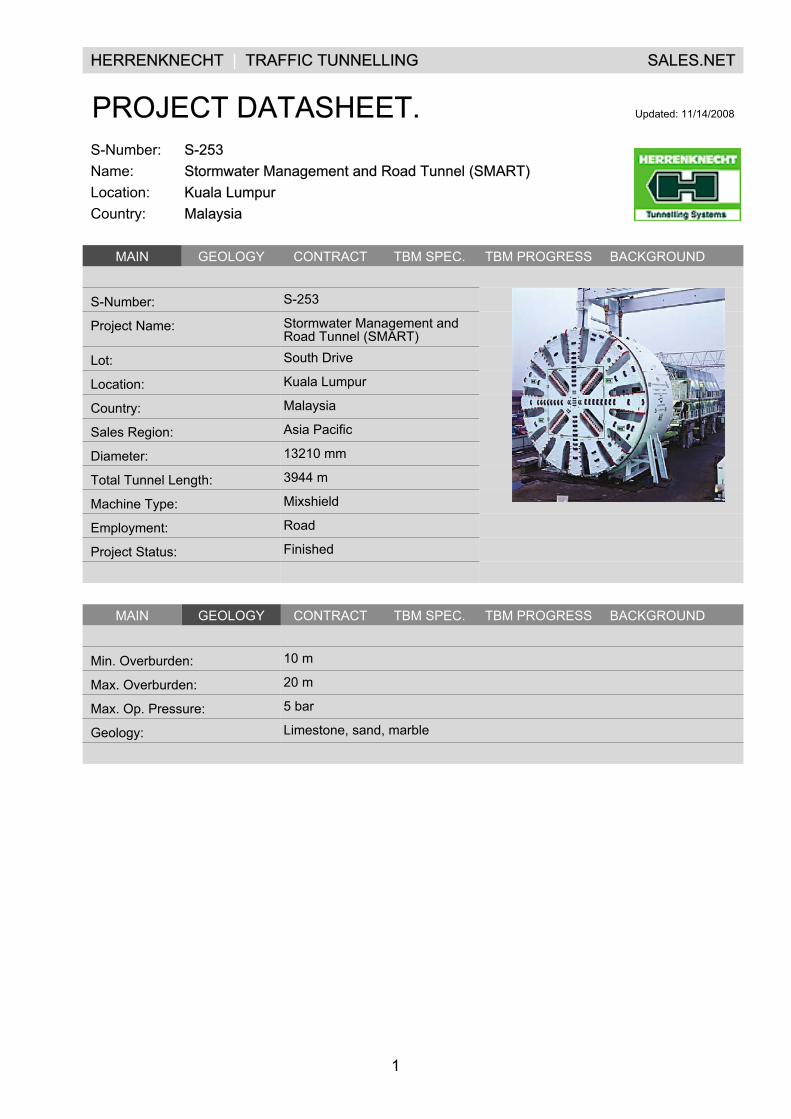
S-253Stormwater Management and Road Tunnel (SMART)Kuala LumpurMalaysia
.MAIN GEOLOGY CONTRACT TBM SPEC. TBM PROGRESS BACKGROUND .
.
S-Number: S-253 .
Project Name: Stormwater Management andRoad Tunnel (SMART)
.
Lot: South Drive .
Location: Kuala Lumpur .
Country: Malaysia .
Sales Region: Asia Pacific .
Diameter: 13210 mm .
Total Tunnel Length: 3944 m .
Machine Type: Mixshield .
Employment: Road .
Project Status: Finished .
. . .
.MAIN GEOLOGY CONTRACT TBM SPEC. TBM PROGRESS BACKGROUND .
.
Min. Overburden: 10 m
Max. Overburden: 20 m
Max. Op. Pressure: 5 bar
Geology: Limestone, sand, marble
.
.
1
HERRENKNECHT | TRAFFIC TUNNELLING SALES.NET
PROJECT DATASHEET. Updated: 12/12/2008
S-Number:Name:Location:Country:
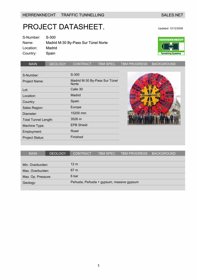
S-300Madrid M-30 By-Pass Sur Túnel NorteMadridSpain
.MAIN GEOLOGY CONTRACT TBM SPEC. TBM PROGRESS BACKGROUND .
.
S-Number: S-300 .
Project Name: Madrid M-30 By-Pass Sur TúnelNorte
.
Lot: Calle 30 .
Location: Madrid .
Country: Spain .
Sales Region: Europe .
Diameter: 15200 mm .
Total Tunnel Length: 3526 m .
Machine Type: EPB Shield .
Employment: Road .
Project Status: Finished .
. . .
.MAIN GEOLOGY CONTRACT TBM SPEC. TBM PROGRESS BACKGROUND .
.
Min. Overburden: 12 m
Max. Overburden: 67 m
Max. Op. Pressure: 6 bar
Geology: Peñuela, Peñuela + gypsum, massive gypsum
.
.
1
HERRENKNECHT | TRAFFIC TUNNELLING SALES.NET
PROJECT DATASHEET. Updated: 11/12/2008
S-Number:Name:Location:Country:
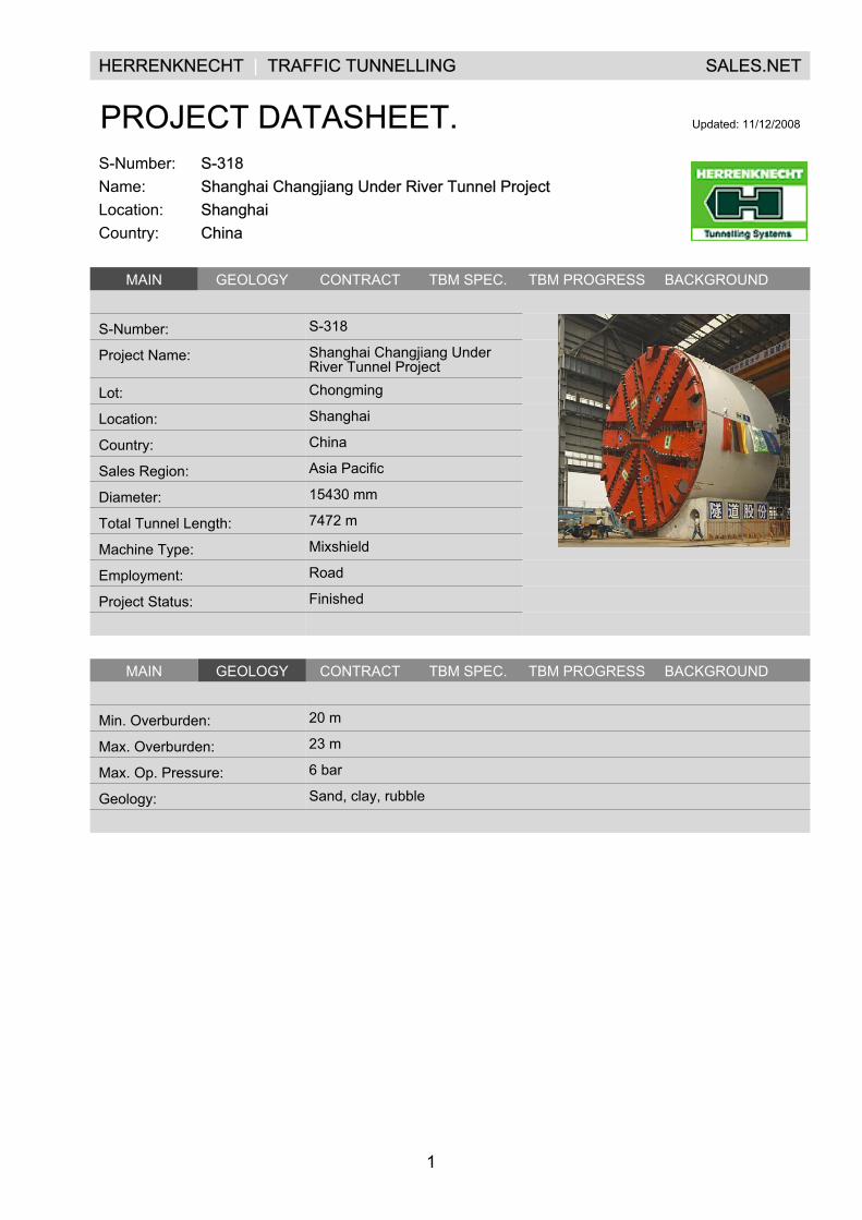
S-318Shanghai Changjiang Under River Tunnel ProjectShanghaiChina
.MAIN GEOLOGY CONTRACT TBM SPEC. TBM PROGRESS BACKGROUND .
.
S-Number: S-318 .
Project Name: Shanghai Changjiang UnderRiver Tunnel Project
.
Lot: Chongming .
Location: Shanghai .
Country: China .
Sales Region: Asia Pacific .
Diameter: 15430 mm .
Total Tunnel Length: 7472 m .
Machine Type: Mixshield .
Employment: Road .
Project Status: Finished .
. . .
.MAIN GEOLOGY CONTRACT TBM SPEC. TBM PROGRESS BACKGROUND .
.
Min. Overburden: 20 m
Max. Overburden: 23 m
Max. Op. Pressure: 6 bar
Geology: Sand, clay, rubble
.
.
1
HERRENKNECHT | TRAFFIC TUNNELLING SALES.NET
PROJECT DATASHEET. Updated: 9/4/2008
S-Number:Name:Location:Country:
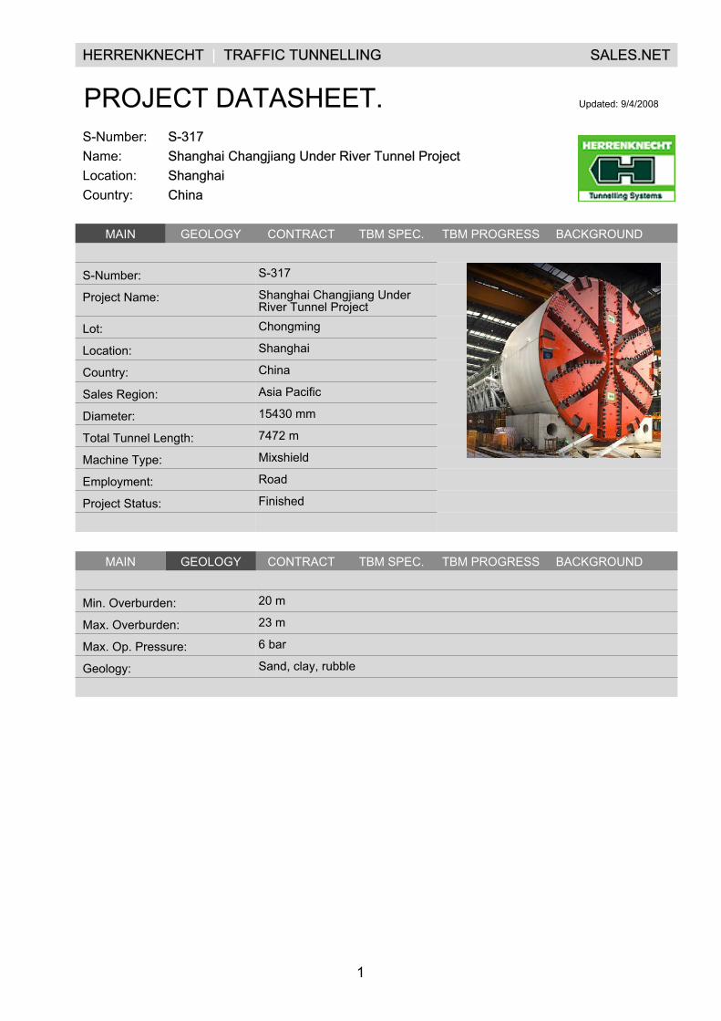
S-317Shanghai Changjiang Under River Tunnel ProjectShanghaiChina
.MAIN GEOLOGY CONTRACT TBM SPEC. TBM PROGRESS BACKGROUND .
.
S-Number: S-317 .
Project Name: Shanghai Changjiang UnderRiver Tunnel Project
.
Lot: Chongming .
Location: Shanghai .
Country: China .
Sales Region: Asia Pacific .
Diameter: 15430 mm .
Total Tunnel Length: 7472 m .
Machine Type: Mixshield .
Employment: Road .
Project Status: Finished .
. . .
.MAIN GEOLOGY CONTRACT TBM SPEC. TBM PROGRESS BACKGROUND .
.
Min. Overburden: 20 m
Max. Overburden: 23 m
Max. Op. Pressure: 6 bar
Geology: Sand, clay, rubble
.
.

1
HERRENKNECHT | TRAFFIC TUNNELLING SALES.NET
PROJECT DATASHEET. Updated: 12/3/2008
S-Number:Name:Location:Country:
S-349NanjingNanjingChina
.MAIN GEOLOGY CONTRACT TBM SPEC. TBM PROGRESS BACKGROUND .
.
S-Number: S-349 .
Project Name: Nanjing .
Lot: Right Tunnel .
Location: Nanjing .
Country: China .
Sales Region: Asia Pacific .
Diameter: 14930 mm .
Total Tunnel Length: 2933 m .
Machine Type: Mixshield .
Employment: Road .
Project Status: Tunnelling .
. . .
.MAIN GEOLOGY CONTRACT TBM SPEC. TBM PROGRESS BACKGROUND .
.
Min. Overburden: 6 m
Max. Overburden: 30 m
Max. Op. Pressure: 7.5 bar
Geology: Silt, sand, clay, gravel
.
.
1
HERRENKNECHT | TRAFFIC TUNNELLING SALES.NET
PROJECT DATASHEET. Updated: 12/3/2008
S-Number:Name:Location:Country:
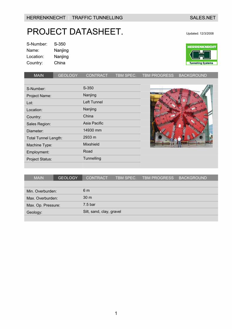
S-350NanjingNanjingChina
.MAIN GEOLOGY CONTRACT TBM SPEC. TBM PROGRESS BACKGROUND .
.
S-Number: S-350 .
Project Name: Nanjing .
Lot: Left Tunnel .
Location: Nanjing .
Country: China .
Sales Region: Asia Pacific .
Diameter: 14930 mm .
Total Tunnel Length: 2933 m .
Machine Type: Mixshield .
Employment: Road .
Project Status: Tunnelling .
. . .
.MAIN GEOLOGY CONTRACT TBM SPEC. TBM PROGRESS BACKGROUND .
.
Min. Overburden: 6 m
Max. Overburden: 30 m
Max. Op. Pressure: 7.5 bar
Geology: Silt, sand, clay, gravel
.
.
1
HERRENKNECHT | TRAFFIC TUNNELLING SALES.NET
PROJECT DATASHEET. Updated: 12/3/2008
S-Number:Name:Location:Country:
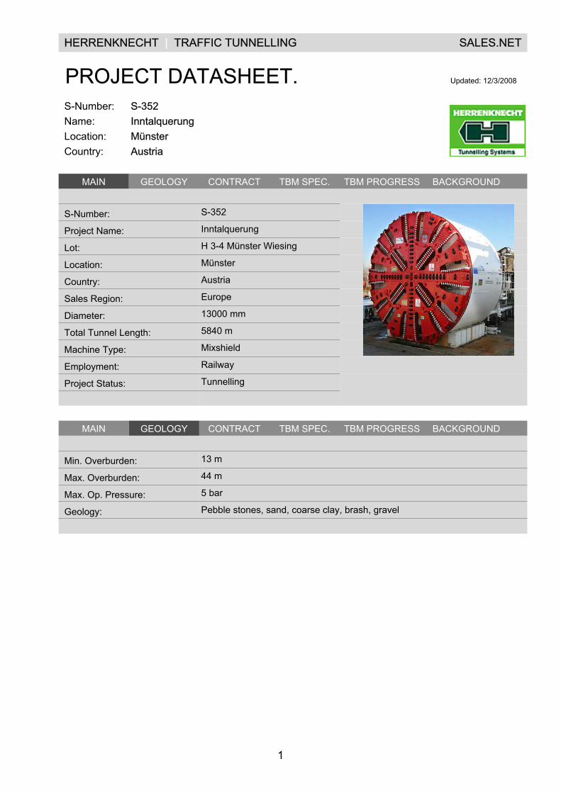
S-352InntalquerungMünsterAustria
.MAIN GEOLOGY CONTRACT TBM SPEC. TBM PROGRESS BACKGROUND .
.
S-Number: S-352 .
Project Name: Inntalquerung .
Lot: H 3-4 Münster Wiesing .
Location: Münster .
Country: Austria .
Sales Region: Europe .
Diameter: 13000 mm .
Total Tunnel Length: 5840 m .
Machine Type: Mixshield .
Employment: Railway .
Project Status: Tunnelling .
. . .
.MAIN GEOLOGY CONTRACT TBM SPEC. TBM PROGRESS BACKGROUND .
.
Min. Overburden: 13 m
Max. Overburden: 44 m
Max. Op. Pressure: 5 bar
Geology: Pebble stones, sand, coarse clay, brash, gravel
.
.
1
HERRENKNECHT | TRAFFIC TUNNELLING SALES.NET
PROJECT DATASHEET. Updated: 12/3/2008
S-Number:Name:Location:Country:
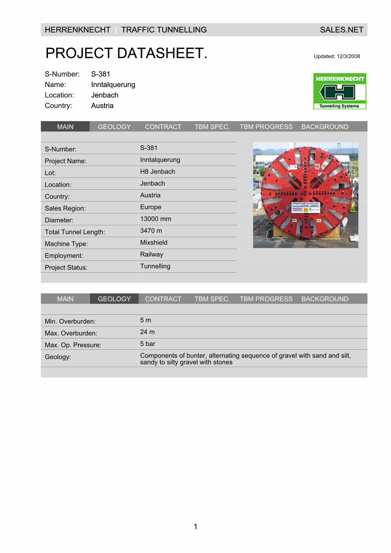
S-381InntalquerungJenbachAustria
.MAIN GEOLOGY CONTRACT TBM SPEC. TBM PROGRESS BACKGROUND .
.
S-Number: S-381 .
Project Name: Inntalquerung .
Lot: H8 Jenbach .
Location: Jenbach .
Country: Austria .
Sales Region: Europe .
Diameter: 13000 mm .
Total Tunnel Length: 3470 m .
Machine Type: Mixshield .
Employment: Railway .
Project Status: Tunnelling .
. . .
.MAIN GEOLOGY CONTRACT TBM SPEC. TBM PROGRESS BACKGROUND .
.
Min. Overburden: 5 m
Max. Overburden: 24 m
Max. Op. Pressure: 5 bar
Geology: Components of bunter, alternating sequence of gravel with sand and silt,sandy to silty gravel with stones
.
.
1
HERRENKNECHT | TRAFFIC TUNNELLING SALES.NET
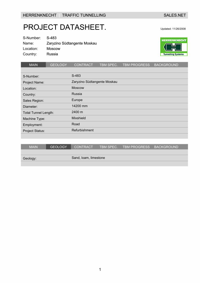
PROJECT DATASHEET. Updated: 11/26/2008
S-Number:Name:Location:Country:
S-483Zaryzino Südtangente MoskauMoscowRussia
.MAIN GEOLOGY CONTRACT TBM SPEC. TBM PROGRESS BACKGROUND .
.
S-Number: S-483
Project Name: Zaryzino Südtangente Moskau
Location: Moscow
Country: Russia
Sales Region: Europe
Diameter: 14200 mm
Total Tunnel Length: 2400 m
Machine Type: Mixshield
Employment: Road
Project Status: Refurbishment
.
.MAIN GEOLOGY CONTRACT TBM SPEC. TBM PROGRESS BACKGROUND .
.
Geology: Sand, loam, limestone
.
.
1
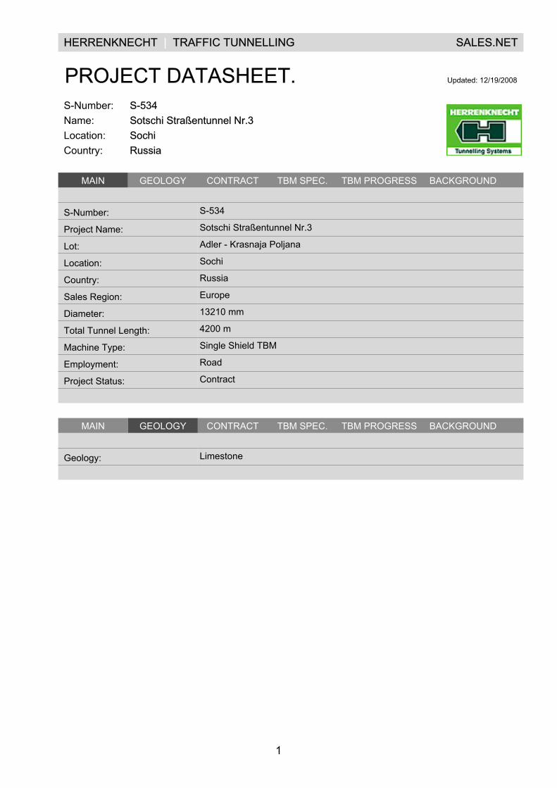
HERRENKNECHT | TRAFFIC TUNNELLING SALES.NET
PROJECT DATASHEET. Updated: 12/19/2008
S-Number:Name:Location:Country:
S-534Sotschi Straßentunnel Nr.3SochiRussia
.MAIN GEOLOGY CONTRACT TBM SPEC. TBM PROGRESS BACKGROUND .
.
S-Number: S-534
Project Name: Sotschi Straßentunnel Nr.3
Lot: Adler - Krasnaja Poljana
Location: Sochi
Country: Russia
Sales Region: Europe
Diameter: 13210 mm
Total Tunnel Length: 4200 m
Machine Type: Single Shield TBM
Employment: Road
Project Status: Contract
.
.MAIN GEOLOGY CONTRACT TBM SPEC. TBM PROGRESS BACKGROUND .
.
Geology: Limestone
.
.
H E
R R
E N
K N
E C
H T
A
G
| U
T I
L I T
Y
T U
N N
E L
L I
N G
|
T R
A F
F I
C
T U
N N
E L
L I
N G
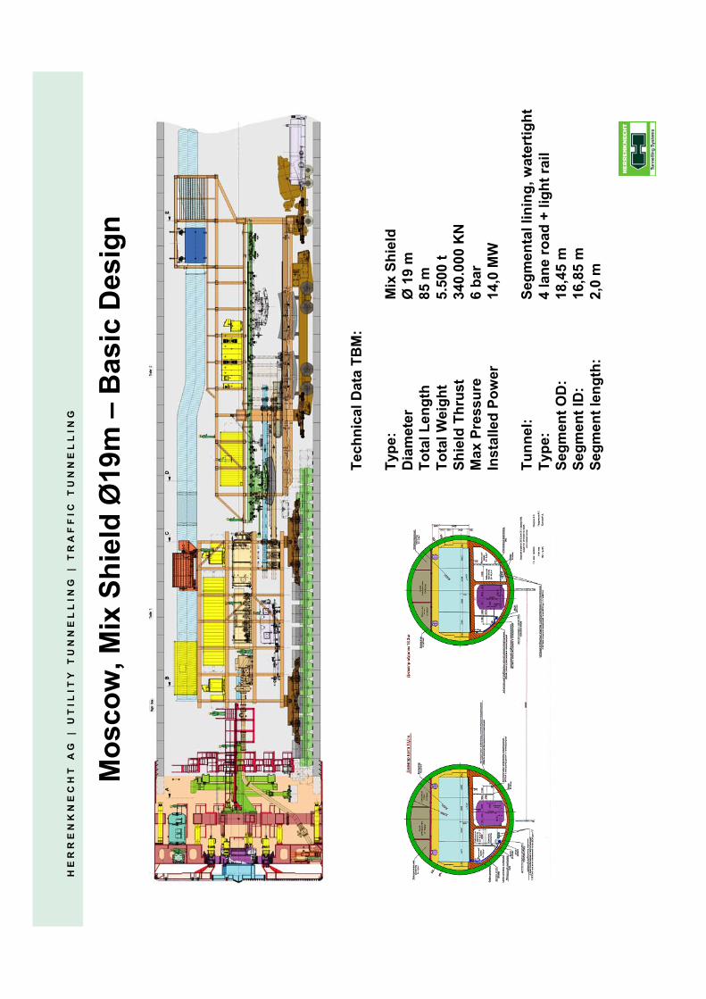
Mos
cow
, Mix
Shi
eld
Ø19
m –
Bas
ic D
esig
n
Tech
nica
l Dat
a TB
M:
Type
:M
ix S
hiel
dD
iam
eter
Ø
19 m
Tota
l Len
gth
85 m
Tota
l Wei
ght
5.50
0 t
Shie
ld T
hrus
t34
0.00
0 K
NM
ax P
ress
ure
6 ba
rIn
stal
led
Pow
er14
,0 �
W
Tunn
el:
Segm
enta
l lin
ing,
wat
ertig
htTy
pe:
4 la
ne ro
ad +
ligh
t rai
lSe
gmen
t OD
:18
,45
mSe
gmen
t ID
:16
,85
mSe
gmen
t len
gth:
2,0
m

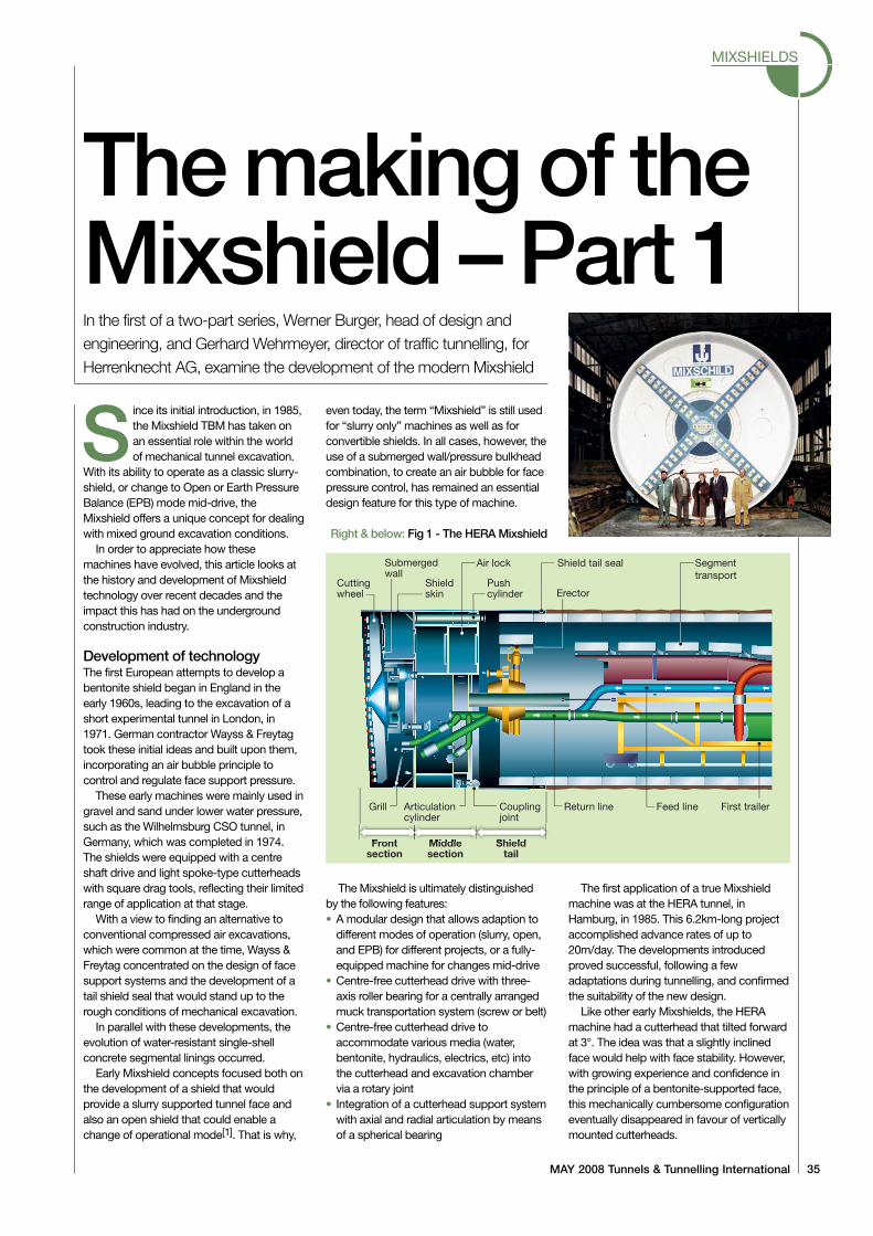
REFERENCE PAPER:
THE MAKING OF THE MIXSHIELD.
MAY 2008 Tunnels & Tunnelling International 35
MIXSHIELDS
Since its initial introduction, in 1985,the Mixshield TBM has taken onan essential role within the worldof mechanical tunnel excavation.
With its ability to operate as a classic slurry-shield, or change to Open or Earth PressureBalance (EPB) mode mid-drive, theMixshield offers a unique concept for dealingwith mixed ground excavation conditions.
In order to appreciate how thesemachines have evolved, this article looks atthe history and development of Mixshieldtechnology over recent decades and theimpact this has had on the undergroundconstruction industry.
Development of technologyThe first European attempts to develop abentonite shield began in England in theearly 1960s, leading to the excavation of ashort experimental tunnel in London, in1971. German contractor Wayss & Freytagtook these initial ideas and built upon them,incorporating an air bubble principle tocontrol and regulate face support pressure.
These early machines were mainly used ingravel and sand under lower water pressure,such as the Wilhelmsburg CSO tunnel, inGermany, which was completed in 1974.The shields were equipped with a centreshaft drive and light spoke-type cutterheadswith square drag tools, reflecting their limitedrange of application at that stage.
With a view to finding an alternative toconventional compressed air excavations,which were common at the time, Wayss &Freytag concentrated on the design of facesupport systems and the development of atail shield seal that would stand up to therough conditions of mechanical excavation.
In parallel with these developments, theevolution of water-resistant single-shellconcrete segmental linings occurred.
Early Mixshield concepts focused both onthe development of a shield that wouldprovide a slurry supported tunnel face andalso an open shield that could enable achange of operational mode[1]. That is why,
even today, the term “Mixshield” is still usedfor “slurry only” machines as well as forconvertible shields. In all cases, however, theuse of a submerged wall/pressure bulkheadcombination, to create an air bubble for facepressure control, has remained an essentialdesign feature for this type of machine.
The Mixshield is ultimately distinguishedby the following features:• A modular design that allows adaption to
different modes of operation (slurry, open,and EPB) for different projects, or a fully-equipped machine for changes mid-drive
• Centre-free cutterhead drive with three-axis roller bearing for a centrally arrangedmuck transportation system (screw or belt)
• Centre-free cutterhead drive toaccommodate various media (water,bentonite, hydraulics, electrics, etc) intothe cutterhead and excavation chambervia a rotary joint
• Integration of a cutterhead support systemwith axial and radial articulation by meansof a spherical bearing
The first application of a true Mixshieldmachine was at the HERA tunnel, inHamburg, in 1985. This 6.2km-long projectaccomplished advance rates of up to20m/day. The developments introducedproved successful, following a fewadaptations during tunnelling, and confirmedthe suitability of the new design.
Like other early Mixshields, the HERAmachine had a cutterhead that tilted forwardat 3°. The idea was that a slightly inclinedface would help with face stability. However,with growing experience and confidence inthe principle of a bentonite-supported face,this mechanically cumbersome configurationeventually disappeared in favour of verticallymounted cutterheads.
Themaking of theMixshield –Part 1In the first of a two-part series, Werner Burger, head of design andengineering, and Gerhard Wehrmeyer, director of traffic tunnelling, forHerrenknecht AG, examine the development of the modern Mixshield
Right & below: Fig 1 - The HERAMixshield
Cuttingwheel
Submergedwall
Grill
Frontsection
Middlesection
Shieldtail
Articulationcylinder
Couplingjoint
Return line
Pushcylinder Erector
Shieldskin
Air lock Shield tail seal Segmenttransport
Feed line First trailer
MIXSHIELDS
36 Tunnels & Tunnelling International MAY 2008
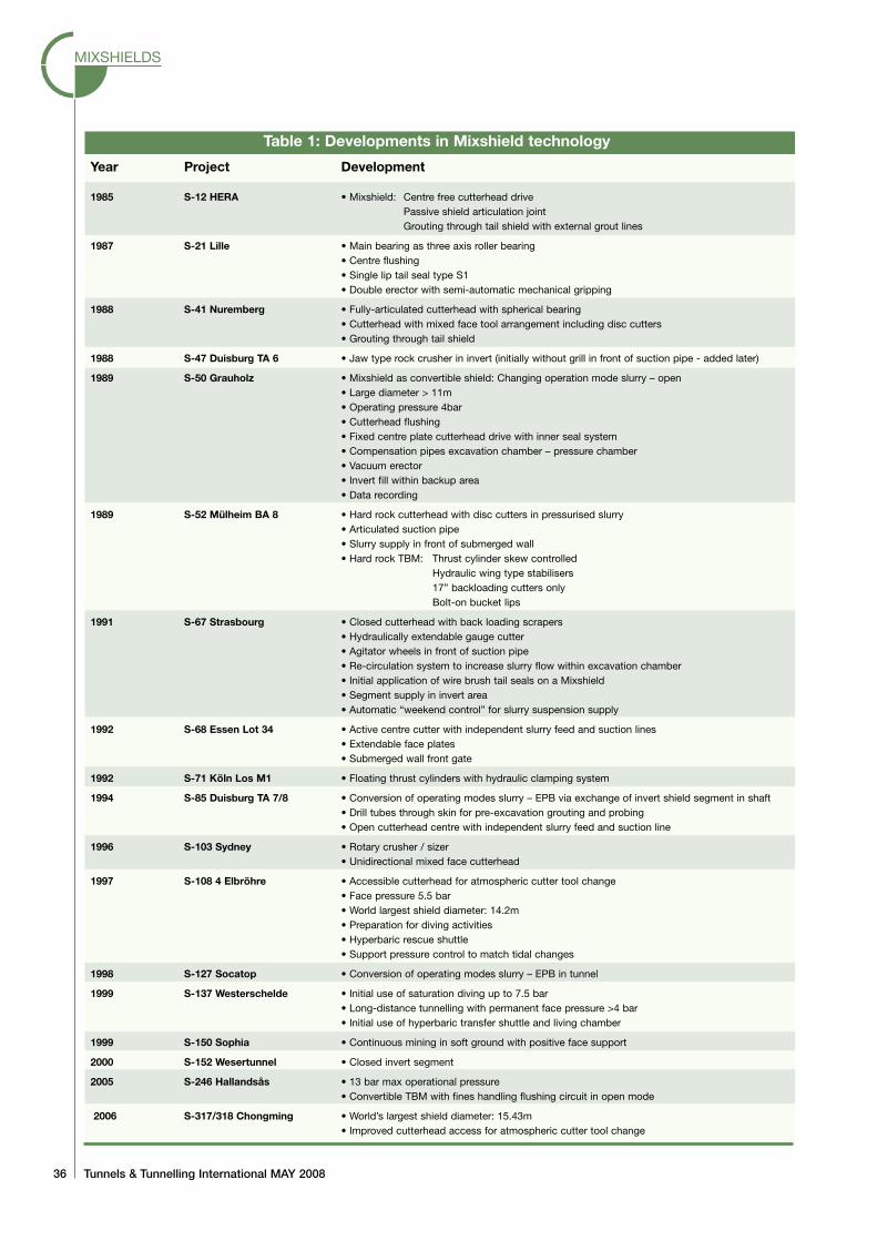
Table 1: Developments in Mixshield technology
Year Project Development
1985 S-12 HERA • Mixshield: Centre free cutterhead drivePassive shield articulation jointGrouting through tail shield with external grout lines
1987 S-21 Lille • Main bearing as three axis roller bearing• Centre flushing• Single lip tail seal type S1• Double erector with semi-automatic mechanical gripping
1988 S-41 Nuremberg • Fully-articulated cutterhead with spherical bearing• Cutterhead with mixed face tool arrangement including disc cutters• Grouting through tail shield
1988 S-47 Duisburg TA 6 • Jaw type rock crusher in invert (initially without grill in front of suction pipe - added later)
1989 S-50 Grauholz • Mixshield as convertible shield: Changing operation mode slurry – open• Large diameter > 11m• Operating pressure 4bar• Cutterhead flushing• Fixed centre plate cutterhead drive with inner seal system• Compensation pipes excavation chamber – pressure chamber• Vacuum erector• Invert fill within backup area• Data recording
1989 S-52 Mülheim BA 8 • Hard rock cutterhead with disc cutters in pressurised slurry• Articulated suction pipe• Slurry supply in front of submerged wall• Hard rock TBM: Thrust cylinder skew controlled
Hydraulic wing type stabilisers17” backloading cutters onlyBolt-on bucket lips
1991 S-67 Strasbourg • Closed cutterhead with back loading scrapers• Hydraulically extendable gauge cutter• Agitator wheels in front of suction pipe• Re-circulation system to increase slurry flow within excavation chamber• Initial application of wire brush tail seals on a Mixshield• Segment supply in invert area• Automatic “weekend control” for slurry suspension supply
1992 S-68 Essen Lot 34 • Active centre cutter with independent slurry feed and suction lines• Extendable face plates• Submerged wall front gate
1992 S-71 Köln Los M1 • Floating thrust cylinders with hydraulic clamping system
1994 S-85 Duisburg TA 7/8 • Conversion of operating modes slurry – EPB via exchange of invert shield segment in shaft• Drill tubes through skin for pre-excavation grouting and probing• Open cutterhead centre with independent slurry feed and suction line
1996 S-103 Sydney • Rotary crusher / sizer• Unidirectional mixed face cutterhead
1997 S-108 4 Elbröhre • Accessible cutterhead for atmospheric cutter tool change• Face pressure 5.5 bar• World largest shield diameter: 14.2m• Preparation for diving activities• Hyperbaric rescue shuttle• Support pressure control to match tidal changes
1998 S-127 Socatop • Conversion of operating modes slurry – EPB in tunnel
1999 S-137 Westerschelde • Initial use of saturation diving up to 7.5 bar• Long-distance tunnelling with permanent face pressure >4 bar• Initial use of hyperbaric transfer shuttle and living chamber
1999 S-150 Sophia • Continuous mining in soft ground with positive face support
2000 S-152 Wesertunnel • Closed invert segment
2005 S-246 Hallandsås • 13 bar max operational pressure• Convertible TBM with fines handling flushing circuit in open mode
2006 S-317/318 Chongming • World’s largest shield diameter: 15.43m• Improved cutterhead access for atmospheric cutter tool change
MIXSHIELDS
MAY 2008 Tunnels & Tunnelling International 37
Another obvious design feature on earlymachines was the wide open, light cuttingwheel design and a large submerged wallopening. It was thought that these wereessential requirements to ensure the bestpossible bentonite circulation and thereforestability of the face. As with the inclined face,however, it became obvious these were notmandatory requirements and that cutterheaddesigns more appropriate to mixed faceconditions could be employed withoutnegative effects on face stability orsettlement. The difference in layout betweenslurry shields and EPB cutterheads thereforestarted to disappear[2]. Today’s cutterheaddesigns are driven by a much wider range offactors – including wear protection, muckflow, tool arrangement and tool access.
In the late 1980s, the potential of Mixshieldmachines became obvious to the tunnellingcommunity. For the next 15 years, projectsand orders were heavily influenced by themarket enthusiastically embracing theconcept. The development of other softground technology, such as compressed airshields and the membrane shield, were allbut abandoned in favour of the Mixshield;which had already enabled the completion ofprojects previously considered impossible.
From a technical point of view, the step-by-step development of the Mixshield (Table1) reads like a technical requirementcatalogue for today’s slurry shields. The onlydifference being that the initial introduction ofany new feature on a given project required ahuge amount of dedication and commitmentfrom all parties throughout the learning curve.
Early milestones included the applicationof a Mixshield, used as a slurry machine, inDuisburg, which adopted a jaw crusher forboulders up to 500mm; the use of a hardrock cutterhead in Mülheim; convertibleoperation modes (closed mode with slurrycircuit – open mode with centre beltconveyor discharge system) for the Grauholztunnel; and Mixshield operation in Strasbourgwith slurry support and closed cutterhead incoarse sand and gravel.
Additional progress was made in the mid-1990s with projects such as the fourth Elbetunnel and the Westerschelde crossing.Since then, advances to larger diameters,higher water pressures and shallower coverhave presented a whole new dimension ofchallenges. Many engineering questions,such as lowering the bentonite level for faceaccess, had to be revisited and newinnovative solutions such as accessiblecutterheads for cutter tool changes underatmospheric conditions were created.
As well as direct improvements toMixshield technology, several more generalTBM developments have also contributed tothe advancement of Mixshields, including:• Articulated cutterheads to allow
overcutting and full control of cutterheadand main bearing loads
• Floating thrust cylinder systems to addressincreased segment length and difficulttunnel alignments
• Mixed and variable face cutterhead andbackloading tool designs
• High-pressure mainbearing, articulationand tailseal concepts
• Vacuum systems for segment erection• Advanced systems for data recording and
processing or process automationMany of these more general developmentshave to be viewed in combination withrelated advancements, e.g. segment designand manufacturing, soil conditioning, sealantmaterials, alignment control and surveysystems, IT systems and data transfer.
In addition to the coventional use ofMixshields for face support in soft ground,the growing use of closed mode operation inrock tunnels has also been seen in recentyears. In water bearing rock with the potentialfor high water inflows and/or pressure, thecontrol of water inflow through thecutterhead is essential for operationalreasons (segment backfill grouting, muckdischarge) and, in many cases, even more sofor environmental reasons.
The traditional approach to such groundconditions is pre-excavation grouting fromwithin the shield ahead of the tunnel face.Depending on rock conditions, pre-groutingactivities can be time-consuming and do notalways guarantee success, especially againstflowing water. To overcome these problems,a closeable single shield rock machine wasdeveloped that would allow pre-excavationgrouting using preventer systems againststatic water pressure. The next logical stepwas to install an additional slurry circuit mucktransport system to deal with worst-casescenarios in closed mode.
Operational modes for such hard rockMixshields include: a) Open mode with dryprimary muck discharge system (e.g.conveyor); b) Open mode with (cyclic) pre-excavation grouting; c) Open mode with(cyclic) pre-excavation grouting in closedstatic conditions; d) Closed mode withhydraulic muck discharge system underreduced face pressure; e) Closed modeunder full-face pressure with potential forpositive face support.
Closed mode, high-pressure operation inhard rock provides the most adverseconditions of operation for all components ofthe machine, but having options d) and e)available is a significant advantage in termsof mitigating potential risk.
The machines for the SMART project inKuala Lumpur, in 2004, produced the secondseries of large Mixshield machines, this timepartially in medium soft rock conditions.
The spotlight regarding large Mixshield
machines is now currently focused on theworld’s largest Mixshield machine, for theChongming project, in Shanghai.
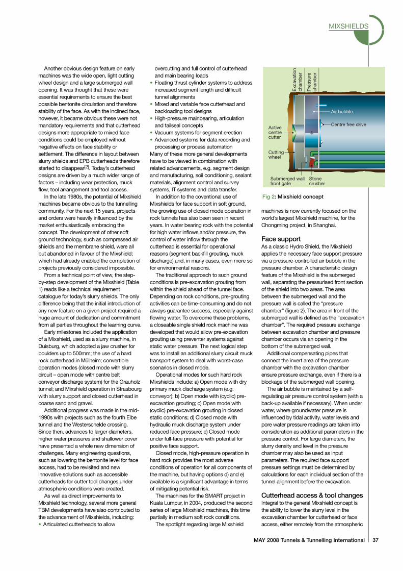
Face supportAs a classic Hydro Shield, the Mixshieldapplies the necessary face support pressurevia a pressure-controlled air bubble in thepressure chamber. A characteristic designfeature of the Mixshield is the submergedwall, separating the pressurised front sectionof the shield into two areas. The areabetween the submerged wall and thepressure wall is called the “pressurechamber” (figure 2). The area in front of thesubmerged wall is defined as the “excavationchamber”. The required pressure exchangebetween excavation chamber and pressurechamber occurs via an opening in thebottom of the submerged wall.
Additional compensating pipes thatconnect the invert area of the pressurechamber with the excavation chamberensure pressure exchange, even if there is ablockage of the submerged wall opening.
The air bubble is maintained by a self-regulating air pressure control system (with aback-up available if necessary). When underwater, where groundwater pressure isinfluenced by tidal activity, water levels andpore water pressure readings are taken intoconsideration as additional parameters in thepressure control. For large diameters, theslurry density and level in the pressurechamber may also be used as inputparameters. The required face supportpressure settings must be determined bycalculations for each individual section of thetunnel alignment before the excavation.
Cutterhead access & tool changesIntegral to the general Mixshield concept isthe ability to lower the slurry level in theexcavation chamber for cutterhead or faceaccess, either remotely from the atmospheric
Activecentrecutter
Centre free drive
Air bubble
Cuttingwheel
Submerged wallfront gate
Stonecrusher
Exc
avat
ion
cham
ber
Pre
ssur
ech
amb
er
Fig 2: Mixshield concept
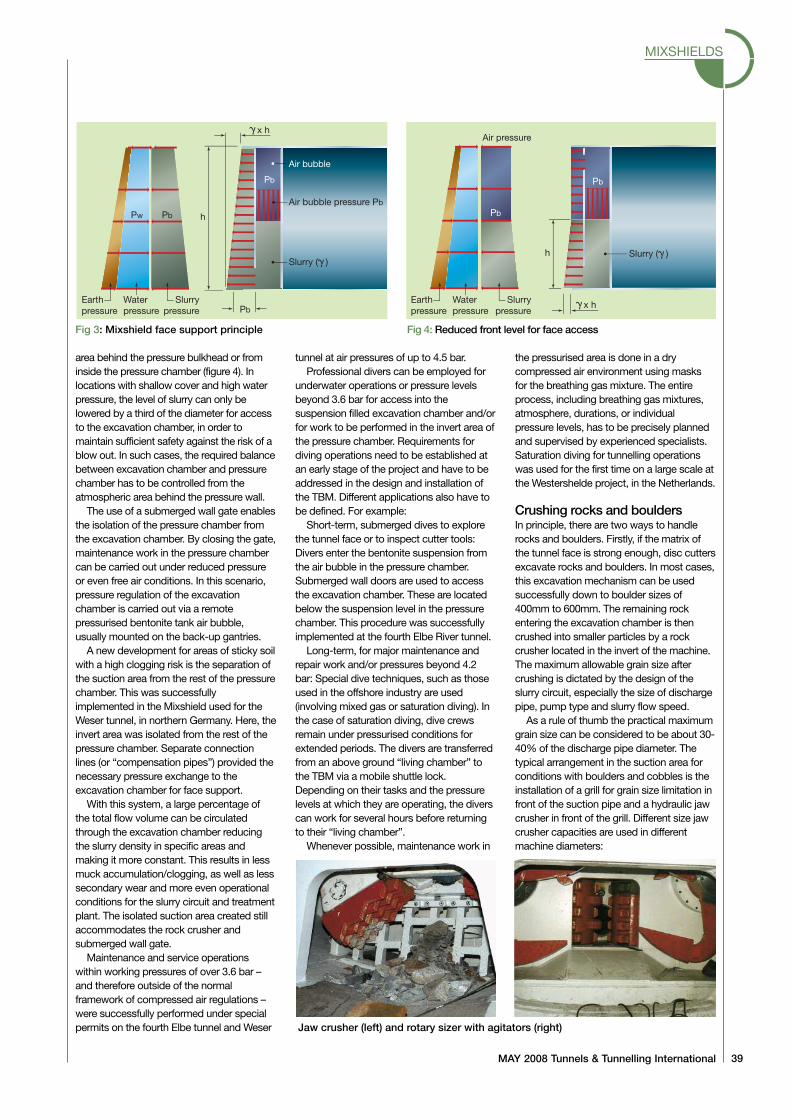
area behind the pressure bulkhead or frominside the pressure chamber (figure 4). Inlocations with shallow cover and high waterpressure, the level of slurry can only belowered by a third of the diameter for accessto the excavation chamber, in order tomaintain sufficient safety against the risk of ablow out. In such cases, the required balancebetween excavation chamber and pressurechamber has to be controlled from theatmospheric area behind the pressure wall.
The use of a submerged wall gate enablesthe isolation of the pressure chamber fromthe excavation chamber. By closing the gate,maintenance work in the pressure chambercan be carried out under reduced pressureor even free air conditions. In this scenario,pressure regulation of the excavationchamber is carried out via a remotepressurised bentonite tank air bubble,usually mounted on the back-up gantries.
A new development for areas of sticky soilwith a high clogging risk is the separation ofthe suction area from the rest of the pressurechamber. This was successfullyimplemented in the Mixshield used for theWeser tunnel, in northern Germany. Here, theinvert area was isolated from the rest of thepressure chamber. Separate connectionlines (or “compensation pipes”) provided thenecessary pressure exchange to theexcavation chamber for face support.
With this system, a large percentage ofthe total flow volume can be circulatedthrough the excavation chamber reducingthe slurry density in specific areas andmaking it more constant. This results in lessmuck accumulation/clogging, as well as lesssecondary wear and more even operationalconditions for the slurry circuit and treatmentplant. The isolated suction area created stillaccommodates the rock crusher andsubmerged wall gate.
Maintenance and service operationswithin working pressures of over 3.6 bar –and therefore outside of the normalframework of compressed air regulations –were successfully performed under specialpermits on the fourth Elbe tunnel and Weser
tunnel at air pressures of up to 4.5 bar.Professional divers can be employed for
underwater operations or pressure levelsbeyond 3.6 bar for access into thesuspension filled excavation chamber and/orfor work to be performed in the invert area ofthe pressure chamber. Requirements fordiving operations need to be established atan early stage of the project and have to beaddressed in the design and installation ofthe TBM. Different applications also have tobe defined. For example:
Short-term, submerged dives to explorethe tunnel face or to inspect cutter tools:Divers enter the bentonite suspension fromthe air bubble in the pressure chamber.Submerged wall doors are used to accessthe excavation chamber. These are locatedbelow the suspension level in the pressurechamber. This procedure was successfullyimplemented at the fourth Elbe River tunnel.
Long-term, for major maintenance andrepair work and/or pressures beyond 4.2bar: Special dive techniques, such as thoseused in the offshore industry are used(involving mixed gas or saturation diving). Inthe case of saturation diving, dive crewsremain under pressurised conditions forextended periods. The divers are transferredfrom an above ground “living chamber” tothe TBM via a mobile shuttle lock.Depending on their tasks and the pressurelevels at which they are operating, the diverscan work for several hours before returningto their “living chamber”.
Whenever possible, maintenance work in
the pressurised area is done in a drycompressed air environment using masksfor the breathing gas mixture. The entireprocess, including breathing gas mixtures,atmosphere, durations, or individualpressure levels, has to be precisely plannedand supervised by experienced specialists.Saturation diving for tunnelling operationswas used for the first time on a large scale atthe Westershelde project, in the Netherlands.
Crushing rocks and bouldersIn principle, there are two ways to handlerocks and boulders. Firstly, if the matrix ofthe tunnel face is strong enough, disc cuttersexcavate rocks and boulders. In most cases,this excavation mechanism can be usedsuccessfully down to boulder sizes of400mm to 600mm. The remaining rockentering the excavation chamber is thencrushed into smaller particles by a rockcrusher located in the invert of the machine.The maximum allowable grain size aftercrushing is dictated by the design of theslurry circuit, especially the size of dischargepipe, pump type and slurry flow speed.
As a rule of thumb the practical maximumgrain size can be considered to be about 30-40% of the discharge pipe diameter. Thetypical arrangement in the suction area forconditions with boulders and cobbles is theinstallation of a grill for grain size limitation infront of the suction pipe and a hydraulic jawcrusher in front of the grill. Different size jawcrusher capacities are used in differentmachine diameters:
MIXSHIELDS
MAY 2008 Tunnels & Tunnelling International 39
Earthpressure
Waterpressure
Slurrypressure
h
Pb
Pb
Pw Pb
x h
Slurry ( )
Air bubble pressure Pb
Air bubble
h
Earthpressure
Waterpressure
Slurrypressure
Air pressure
Pb
Pb
x h
Slurry ( )
Fig 3: Mixshield face support principle Fig 4: Reduced front level for face access
Jaw crusher (left) and rotary sizer with agitators (right)
• 4m-6.5m: max boulder size 500mm• 6m-10m: max boulder size 800mm• 9m: max boulder size 1200mm
Early attempts to use “in-line” crushers orboulder traps in the discharge pipe wereunsuccessful and have therefore nearlydisappeared from modern designs.
The amount, size and consistency of theanticipated rock influences the choice ofcutterhead configuration and cutter tools.Disc cutters are the most effective tools forexcavating hard rock. However, the cuttingtools for handling rocks and boulders with aMixshield require different features in orderto operate under pressurised slurryconditions. In particular, the cutter seal andseal gap design differs, to effectively preventthe penetration of muck and slurry (mudpacking), but also provide the least possiblefriction to ensure the cutters are rollingproperly across the tunnel face. For facepressures above 4 bar, compensating disccutter systems have been developed thatcan handle high outside pressures as well assignificant pressure variations, which on a12m slurry machine is in the range of 1.5 barfrom crown to invert.
If rolling is restricted due to inner friction,or the cutter is jammed, it will no longer beavailable for regular excavation and will onlygrind on one side. Two-ring cutters provide abetter performance at lower single-ringthrust capacity, as they enable severalcutting or face contact patterns for the samenumber of bearing seals and therefore abetter relationship between cutting ring- andinner friction. The use of two-ring cuttersalso requires fewer housing positions on thecutterhead and, for this reason, providesmore options for cutterhead openings to
optimise muck flow.In many cases, the use of two-ring cutters
in the inner face and centre area and single-ring cutters for outer face and periphery areais a good compromise. Grain size limiters inthe muck openings are installed to keeploose rock or large boulders at the tunnelface, so they can be broken down by thecutters. The design and layout of the sizelimiters has to be decided on the basis ofanticipated ground conditions and installedcrusher capacity. Special care also has to begiven to the working levels of the differenttool types on a mixed face cutterhead. Diskcutters should be positioned 30mm to50mm ahead of the soft ground tools toensure that hard rock or boulders are firstattacked by the appropriate tool type.
Positive results have been achieved onseveral mixed face slurry machines usingspecially designed Monoblock cutters, witha reduced risk of secondary wear to non-cutting related elements of the cutters, suchas split rings or hubs.
The combination of mixed face cutterheadtool arrangements and jaw crusher-suctiongrill arrangements has proven effective whendealing with variable face conditions orcobbles and boulders. The need to manuallyintervene in order to remove or split bouldershas been reduced dramatically and can beconsidered an exception these days.
Clogging risksThe problem of clogging can be addressedin several ways: choice of tools, quantity offresh suspension supply, flushing and/oragitation systems in the excavationchamber, flow in the chamber and thegeometrical design and shape of cutterhead,excavation and pressure chamber.
The preferred method in adhesive groundconditions is the use of wide cutting tools, inorder to achieve bigger cuttings or claychips. This also reduces the number of toolsrequired to cover the full face. The use offewer cutting tools increases the free areasbetween the individual tool sockets andtherefore reduces the risk of “bridgebuilding” and adhesion at the cutterhead.
A high circulation or flushing quantity inthe excavation chamber, in combination witha suitable cutterhead design, encouragesfree flow of excavated muck and reducesthe time cuttings remain in the chamber to aminimum. Optimisation of the flow and areduction in the time taken for muck to passthrough the excavation chamber also havepositive effects on wear reduction. This wasdemonstrated on the CTRL’s Thames Tunneldrives, in London, where two Mixshieldswere used to mine through chalk layerscontaining a large amount of abrasive flint.
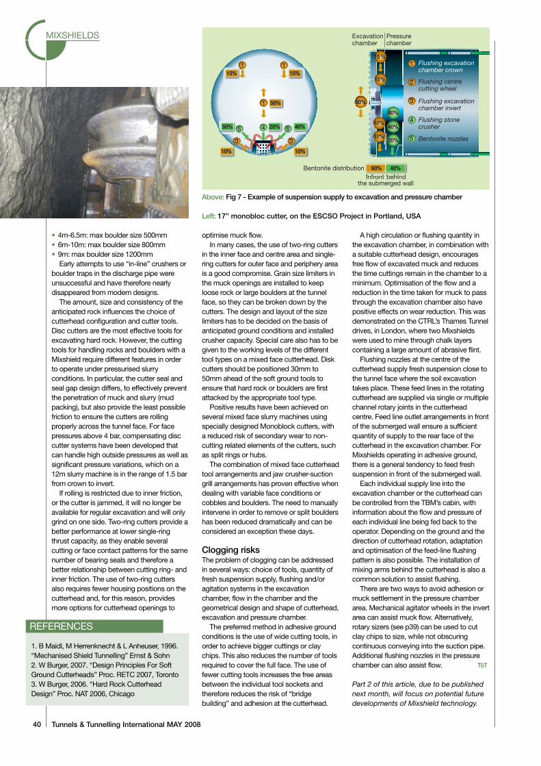
Flushing nozzles at the centre of thecutterhead supply fresh suspension close tothe tunnel face where the soil excavationtakes place. These feed lines in the rotatingcutterhead are supplied via single or multiplechannel rotary joints in the cutterheadcentre. Feed line outlet arrangements in frontof the submerged wall ensure a sufficientquantity of supply to the rear face of thecutterhead in the excavation chamber. ForMixshields operating in adhesive ground,there is a general tendency to feed freshsuspension in front of the submerged wall.
Each individual supply line into theexcavation chamber or the cutterhead canbe controlled from the TBM’s cabin, withinformation about the flow and pressure ofeach individual line being fed back to theoperator. Depending on the ground and thedirection of cutterhead rotation, adaptationand optimisation of the feed-line flushingpattern is also possible. The installation ofmixing arms behind the cutterhead is also acommon solution to assist flushing.
There are two ways to avoid adhesion ormuck settlement in the pressure chamberarea. Mechanical agitator wheels in the invertarea can assist muck flow. Alternatively,rotary sizers (see p39) can be used to cutclay chips to size, while not obscuringcontinuous conveying into the suction pipe.Additional flushing nozzles in the pressurechamber can also assist flow. T&T
Part 2 of this article, due to be publishednext month, will focus on potential futuredevelopments of Mixshield technology.
MIXSHIELDS
40 Tunnels & Tunnelling International MAY 2008
1. B Maidl, M Herrenknecht & L Anheuser, 1996.“Mechanised Shield Tunnelling” Ernst & Sohn2. W Burger, 2007. “Design Principles For SoftGround Cutterheads” Proc. RETC 2007, Toronto3. W Burger, 2006. “Hard Rock CutterheadDesign” Proc. NAT 2006, Chicago
REFERENCES
15%
15%
10%
10%
40%
40%
50%
20%
Flushing excavationchamber crown
Flushing centrecutting wheel
Flushing excavationchamber invert
Flushing stonecrusher
Bentonite distribution
Excavationchamber
Pressurechamber
Infrontthe submerged wall
behind
Bentonite nozzles
11
2
3
4
5
60%
15%
10% 10%
1 50%
50% 20% 40%
115%
40%
45
3 3
5
Left: 17” monobloc cutter, on the ESCSO Project in Portland, USA
Above: Fig 7 - Example of suspension supply to excavation and pressure chamber
REFERENCE PAPER:
LIFTING THE LID ON MIXSHIELD PERFORMANCE.
JUNE 2008 Tunnels & Tunnelling International 31
MIXSHIELDS PART 2
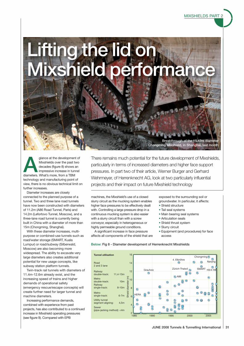
Aglance at the development ofMixshields over the past twodecades (figure 8) shows animpressive increase in tunnel
diameters. What’s more, from a TBMtechnology and manufacturing point ofview, there is no obvious technical limit onfurther increases.
Diameter increases are closelyconnected to the planned purpose of atunnel. Two and three lane road tunnelshave now been constructed with diametersof 11.2m (A86 Road Tunnel, Paris) and14.2m (Lefortovo Tunnel, Moscow), and athree-lane road tunnel is currently beingbuilt in China with a diameter of more than15m (Chongming, Shanghai).
With these diameter increases, multi-purpose or combined-use tunnels such asroad/water storage (SMART, KualaLumpur) or road/subway (Silberwald,Moscow) are also becoming morewidespread. The ability to excavate verylarge diameters also creates additionalpotential for new usage concepts, likesubway station platform tunnels.
Twin-track rail tunnels with diameters of11.4m-12.6m already exist, and theincreasing speed of trains and higherdemands of operational safety(emergency rescue/escape concepts) willcreate further need for larger tunnel andmachine diameters.
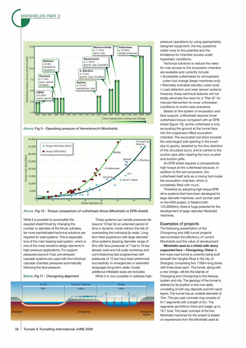
Increasing performance demands,combined with experience from pastprojects, has also contributed to a continuedincrease in Mixshield operating pressures(see figure 9). Compared with EPB
machines, the Mixshield’s use of a closedslurry circuit as the mucking system enableshigher face pressures to be effectively dealtwith. Controlling a large pressure drop in acontinuous mucking system is also easierwith a slurry circuit than with a screwconveyor, especially in heterogeneous orhighly permeable ground conditions.
A significant increase in face pressureaffects all components of the shield that are
exposed to the surrounding soil orgroundwater. In particular, it affects:• Shield structure• Tail seal systems• Main bearing seal systems• Articulation seals• Shield thrust system• Slurry circuit• Equipment (and procedures) for face
access
Lifting the lid onMixshield performance
There remains much potential for the future development of Mixshields,particularly in terms of increased diameters and higher face supportpressures. In part two of their article, Werner Burger and GerhardWehrmeyer, of Herrenknecht AG, look at two particularly influentialprojects and their impact on future Mixshield technology
Below: Fig 8 - Diameter development of Herrenknecht Mixshields
16
14
12
10
8
6
4
2
Road2 and 3 lane
Tunnel utilisation
Railwaydouble-track: 11,4-13m
Metrodouble-track: 10m
Metrosingle-track: 6-7m
Utility tunnelsegment aligning: 4,5m
Sewer(pipe-jacking method): <4m
Railwaysingle-track: 8-10m
Shi
eld
dia
met
er(m
)
1985 1990 1995 2000 2005
HERA
Grauholz
4. ElbröhreChongming
Nanjing
SMART H3/4 H8Zürich-Thalwil
A86
Breakthrough of the 15.43m diameterChongming Mixshield, in Shanghai, last month
MIXSHIELDS PART 2
32 Tunnels & Tunnelling International JUNE 2008
While it is possible to accomplish therequired shield thrust by changing thenumber or diameter of the thrust cylinders,far more sophisticated technical solutions arerequired for seal systems. This is especiallytrue of the main bearing seal system, which isone of the most sensitive design elements inhigh-pressure applications. For supportpressures beyond 4 bar, pre-stressedcascade systems are used with the individualcascade chamber pressures automaticallyfollowing the face pressure.
These systems can handle pressures farbeyond 10 bar for an extended period oftime in dynamic mode without the risk ofoverloading the individual lip seals. Long-term field experience with large diameterdrive systems (bearing diameter range of6m) with face pressures of 7 bar to 10 baralready exist and full scale workshop andcommissioning test programmes withpressures of 15 bar have been performedsuccessfully. In emergencies or extendedstoppages (long-term static mode),additional inflatable seals are included.
While it is now possible to address high-
pressure operations by using appropriatelydesigned equipment, the key questionsrelate more to the potential and thelimitations for chamber access underhyperbaric conditions.
Technical solutions to reduce the needfor man access to the excavation chamberare available and currently include:• Accessible cutterheads for atmospheric
cutter tool change (larger machines only)• Remotely activated standby cutter tools• Load detection and wear sensor systemsHowever, these technical features will nottotally eliminate the need for a “Plan B” formanual intervention to cover unforeseenconditions or worst-case scenarios.
Based on the system of excavation andface support, a Mixshield requires lowercutterhead torque compared with an EPBshield (figure 10), as the cutterhead is onlyexcavating the ground at the tunnel faceinto the suspension-filled excavationchamber. The excavated soil sinks towardsthe submerged wall opening in the invertdue to gravity, assisted by the flow directionof the circulated slurry, and is carried to thesuction pipe after clearing the rock crusherand suction grille.
An EPB shield requires a comparativelyhigh torque at the cutterhead because, inaddition to the soil excavation, thecutterhead itself acts as a mixing tool insidethe excavation chamber, which iscompletely filled with muck.
Therefore by adopting high torque EPBdrive systems that have been developed forlarge diameter machines, such as that usedon the M30 project, in Madrid (with125,000kNm), there is huge potential for thedevelopment of larger diameter Mixshieldmachines.
Examples of projectsThe following presentation of theChongming and A86 tunnel projectsdemonstrates the efficiency of currentMixshields and the value of development.
Mixshield used as a shield with slurrysupported face – Chongming, China: Atwin tube road tunnel is currently being builtbeneath the Yangtze River in the city ofShanghai, comprising two 7160m-long boreswith three lanes each. The tunnel, along witha new bridge, will link the islands ofChangxing and Chongming to the freewaysystem and city. The geology of the tunnel isdefined by its position in the river delta,consisting of soft clay deposits and thin sandlayers. The tunnel has an outside diameter of15m. The pre-cast concrete ring consists of9+1 segments with a length of 2m. Thesegments are 640mm thick and weigh up to16.7 tons. The basic concept of the twoMixshield machines for the project is basedon experiences from the Mixshield used at
15.0
12.5
10.0
7.5
5.0
2.5
0.0
Op
erat
ing
pre
ssur
ed
urin
gad
vanc
e[b
ar]
2.5
3.5 3.54.0
5.5
7.5
13.0
HERAø 5.95msand, gravel
Grauholzø 11.6msand, gravelmolasse
Mülheimø 6.9msandstone,mudstone
Sydneyø 10.4msandstone, clay
4. Elbröhreø 14.2mgravel, clay, boulders
Wesertunnelø 11.67mgravel, clay, boulders
Westerscheldeø 11.34msand, clay
Hallandsasø 10.53mdesign pressure
Diver assignment cutting tool change
1985 1986 1987 1988 1989 1990 1991 1992 1993 1994 1995 1996 1997 1998 1999 2000 2001 2000 2003
Above: Fig 9 - Operating pressure of Herrenknecht Mixshields
40,000
35,000
30,000
25,000
20,000
15,000
10,000
5,000
0
Torq
uem
ain
driv
e[k
Nm
]
2 4 6 8 10 12 14 16Shield diameter [m]
Design Mixshield [kNm]
Design EPB [kNm]
Grauholz
4. Elbröhre
Chongming,Nanjing
SMART
H3/4
H8Hallandsas
Zürich-Thalwil
A86
Above: Fig 10 - Torque comparison of cutterhead drives (Mixshield vs EPB-shield)
Tunnel
9km
Elevated highway
6.5km
Bridge
10km
Shanghai Changxing ChongmingIsland
Below: Fig 11 - Chongming alignment
the fourth Elbe Tunnel and advancements inlarge diameter shield developments in highwater pressure conditions. With a shielddiameter of 15.43m, the two machines arecurrently the world’s largest diameter shields.
The Mixshield machines have followingtechnical features:• The shields are designed for an
anticipated operational pressure of 6 barat springline level. Due to the underwaterapplication, and nearly straight alignment,(Rmin = 4.000m), a shield articulation jointwas not included
• The invert area of the Mixshield isequipped with two agitator wheels(Ø1.900mm), which assist the materialflow to the grille and a 500mm diametersuction pipe. Submerged wall gate,bentonite nozzles, cutting wheel andextensive excavation chamber flushingarrangements complete the Mixshieldconfiguration to address the soft soilconditions and potential clogging risks
• The double shell tailskin with integratedgrout lines has a three-row wire brush sealand an inflatable emergency seal system.Furthermore, freezing lines are integratedinto the tail shield, which, in case ofemergency, can be used for groundfreezing around the machine to minimisethe risk of water inrush during brush sealchanges or repair works
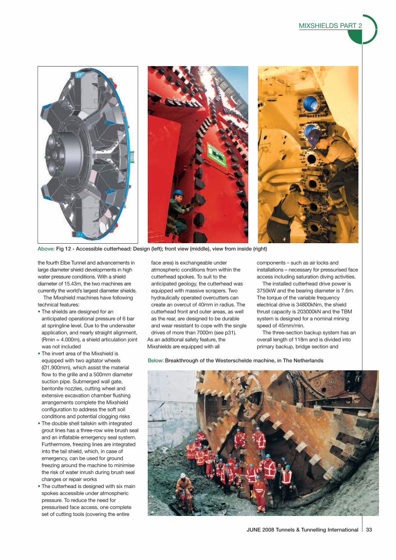
• The cutterhead is designed with six mainspokes accessible under atmosphericpressure. To reduce the need forpressurised face access, one completeset of cutting tools (covering the entire
face area) is exchangeable underatmospheric conditions from within thecutterhead spokes. To suit to theanticipated geology, the cutterhead wasequipped with massive scrapers. Twohydraulically operated overcutters cancreate an overcut of 40mm in radius. Thecutterhead front and outer areas, as wellas the rear, are designed to be durableand wear resistant to cope with the singledrives of more than 7000m (see p31).
As an additional safety feature, theMixshields are equipped with all
components – such as air locks andinstallations – necessary for pressurised faceaccess including saturation diving activities.
The installed cutterhead drive power is3750kW and the bearing diameter is 7.6m.The torque of the variable frequencyelectrical drive is 34800kNm, the shieldthrust capacity is 203000kN and the TBMsystem is designed for a nominal miningspeed of 45mm/min.
The three-section backup system has anoverall length of 118m and is divided intoprimary backup, bridge section and
Above: Fig 12 - Accessible cutterhead: Design (left); front view (middle), view from inside (right)
Below: Breakthrough of the Westerschelde machine, in The Netherlands
MIXSHIELDS PART 2
JUNE 2008 Tunnels & Tunnelling International 33
MIXSHIELDS PART 2
34 Tunnels & Tunnelling International JUNE 2008
secondary backup.The primary backup, or first three-deck
trailer, contains all the hydraulic powerpacks and electrical systems for the supplyand operation of the shield, along withslurry pumps and backfill grout system. Foran even distribution of the wheel loads thetrailer contains an integrated supportsystem of auxiliary rail elements (steel invertslabs) and multi-wheel sets. Theprefabricated 35 ton invert elements areinstalled in the area under the 67m bridgesection. The supply crane system isinstalled inside the bridge cross-section totransfer segments, grout and otherconsumables to the TBM. All installationsand workplaces for extension of servicesare located in the third section, along withancillary equipment.
The machine is supplied with segmentsand grout by rubber-tired transportvehicles, which travel in convoy and carry
either segments only or segments andgrout tanks. The segment transfer on thebackup is done by segment crane and asegment feeder. The grout is supplied intransfer tanks to the first backup.
The shield structures and assemblies ofthe 132m-long and 2,300 ton TBMs weremanufactured in Shanghai. Cutterheadsand other main components such as driveassemblies and thrust cylinders weremanufactured in Germany and shipped toChina. After shop acceptance, the TBMwas disassembled and transported to thestart shaft about 6km from the workshop.
Tunnelling started for the first tube inSeptember 2006, and in January 2007 forthe second. In March 2008, the first 7160mtunnel was about 90% complete and thesecond about 70%. Constant weeklyperformances of 90-120m are now beingachieved by each TBM. Both drives arescheduled to finish in 2008 (the first TBM inMay, and second in September), almost ayear ahead of the project schedule.
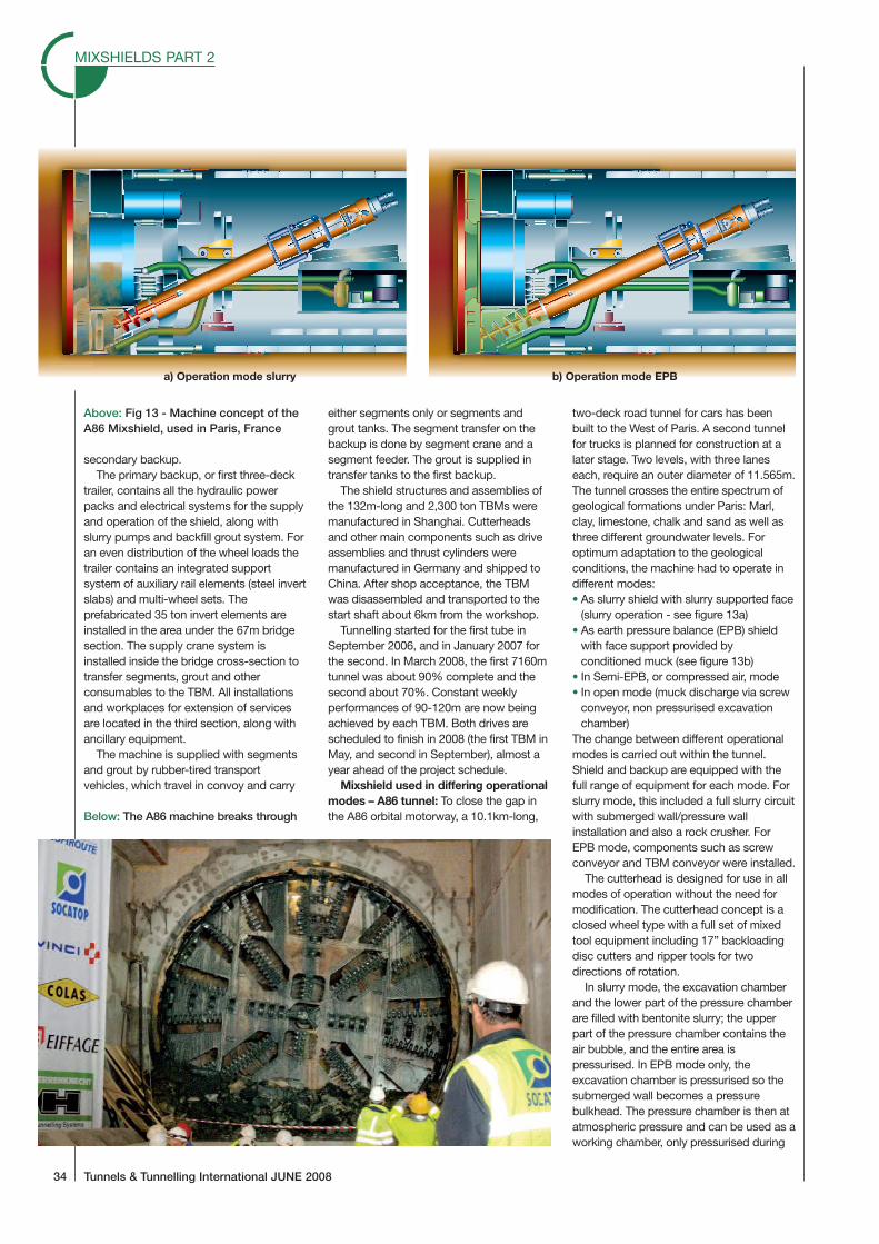
Mixshield used in differing operationalmodes – A86 tunnel: To close the gap inthe A86 orbital motorway, a 10.1km-long,
two-deck road tunnel for cars has beenbuilt to the West of Paris. A second tunnelfor trucks is planned for construction at alater stage. Two levels, with three laneseach, require an outer diameter of 11.565m.The tunnel crosses the entire spectrum ofgeological formations under Paris: Marl,clay, limestone, chalk and sand as well asthree different groundwater levels. Foroptimum adaptation to the geologicalconditions, the machine had to operate indifferent modes:• As slurry shield with slurry supported face
(slurry operation - see figure 13a)• As earth pressure balance (EPB) shield
with face support provided byconditioned muck (see figure 13b)
• In Semi-EPB, or compressed air, mode• In open mode (muck discharge via screw
conveyor, non pressurised excavationchamber)
The change between different operationalmodes is carried out within the tunnel.Shield and backup are equipped with thefull range of equipment for each mode. Forslurry mode, this included a full slurry circuitwith submerged wall/pressure wallinstallation and also a rock crusher. ForEPB mode, components such as screwconveyor and TBM conveyor were installed.
The cutterhead is designed for use in allmodes of operation without the need formodification. The cutterhead concept is aclosed wheel type with a full set of mixedtool equipment including 17” backloadingdisc cutters and ripper tools for twodirections of rotation.
In slurry mode, the excavation chamberand the lower part of the pressure chamberare filled with bentonite slurry; the upperpart of the pressure chamber contains theair bubble, and the entire area ispressurised. In EPB mode only, theexcavation chamber is pressurised so thesubmerged wall becomes a pressurebulkhead. The pressure chamber is then atatmospheric pressure and can be used as aworking chamber, only pressurised during
a) Operation mode slurry b) Operation mode EPB
Above: Fig 13 - Machine concept of theA86 Mixshield, used in Paris, France
Below: The A86 machine breaks through
face access. To change from EPB to slurrymode, the entire screw casing is movedback, thus clearing the submerged wallopening in the invert and the suction grillebelow. After this, a specially designed jawcrusher moves from parked position tooperational mode.
Some of the slurry mode installations,such as the air bubble pressure regulationsystem or the bentonite circulationsystems, can also be used in EPB modewhen required. Having the two systemspermanently available provides potentialsynergy.
Apart from the ability to change modesof operation, the TBM also has thefollowing technical key features:• To cater for EPB mode, installed
cutterhead power is 4000kW and theavailable cutterhead torque is35000kN/m. Shield thrust is 150000kN,and the designed advance speed is80mm/min
• The slurry circuit with 1900m³/h flowvolume is designed for a mining speed of50mm/min in slurry mode. The tunnel isruns uphill and the largest difference inheight between portal and TBM is 160m.This configuration needed to be
addressed in the design of the slurrycircuit as, under some conditions, thefriction losses in the discharge line areless than the geometrical height betweenTBM and treatment plant
• A specially designed camera system forthe excavation chamber was installed forthe first time and successfully tested insemi EPB/compressed air or open mode
• Due to the steep tunnel gradient of 4.5%rubber tired vehicles were used forsegment and grout transport. At thetunnel portal a semi-automatic loadingstation for the vehicles was installedloading one complete multi stacktruckload at the same time, whichtogether with a quick unloading system inthe gantry reduced the turnaround cycles
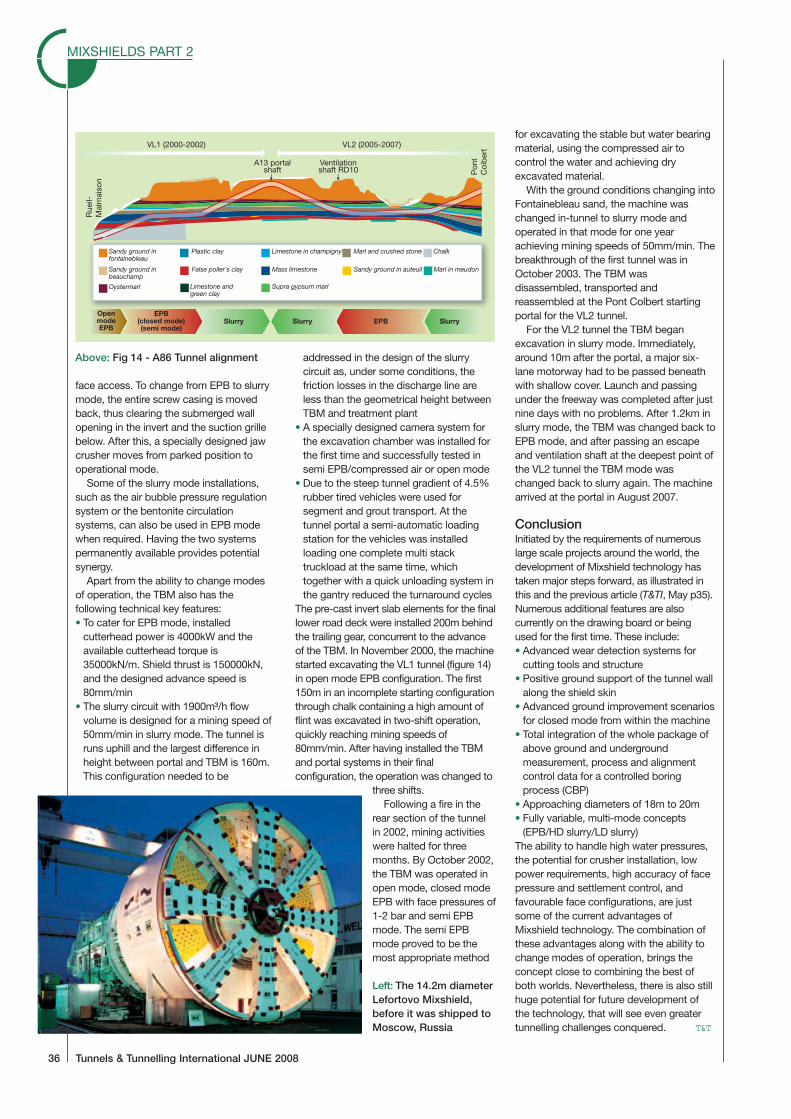
The pre-cast invert slab elements for the finallower road deck were installed 200m behindthe trailing gear, concurrent to the advanceof the TBM. In November 2000, the machinestarted excavating the VL1 tunnel (figure 14)in open mode EPB configuration. The first150m in an incomplete starting configurationthrough chalk containing a high amount offlint was excavated in two-shift operation,quickly reaching mining speeds of80mm/min. After having installed the TBMand portal systems in their finalconfiguration, the operation was changed to
three shifts.Following a fire in the
rear section of the tunnelin 2002, mining activitieswere halted for threemonths. By October 2002,the TBM was operated inopen mode, closed modeEPB with face pressures of1-2 bar and semi EPBmode. The semi EPBmode proved to be themost appropriate method
for excavating the stable but water bearingmaterial, using the compressed air tocontrol the water and achieving dryexcavated material.
With the ground conditions changing intoFontainebleau sand, the machine waschanged in-tunnel to slurry mode andoperated in that mode for one yearachieving mining speeds of 50mm/min. Thebreakthrough of the first tunnel was inOctober 2003. The TBM wasdisassembled, transported andreassembled at the Pont Colbert startingportal for the VL2 tunnel.
For the VL2 tunnel the TBM beganexcavation in slurry mode. Immediately,around 10m after the portal, a major six-lane motorway had to be passed beneathwith shallow cover. Launch and passingunder the freeway was completed after justnine days with no problems. After 1.2km inslurry mode, the TBM was changed back toEPB mode, and after passing an escapeand ventilation shaft at the deepest point ofthe VL2 tunnel the TBM mode waschanged back to slurry again. The machinearrived at the portal in August 2007.
ConclusionInitiated by the requirements of numerouslarge scale projects around the world, thedevelopment of Mixshield technology hastaken major steps forward, as illustrated inthis and the previous article (T&TI, May p35).Numerous additional features are alsocurrently on the drawing board or beingused for the first time. These include:• Advanced wear detection systems for
cutting tools and structure• Positive ground support of the tunnel wall
along the shield skin• Advanced ground improvement scenarios
for closed mode from within the machine• Total integration of the whole package of
above ground and undergroundmeasurement, process and alignmentcontrol data for a controlled boringprocess (CBP)
• Approaching diameters of 18m to 20m• Fully variable, multi-mode concepts
(EPB/HD slurry/LD slurry)The ability to handle high water pressures,the potential for crusher installation, lowpower requirements, high accuracy of facepressure and settlement control, andfavourable face configurations, are justsome of the current advantages ofMixshield technology. The combination ofthese advantages along with the ability tochange modes of operation, brings theconcept close to combining the best ofboth worlds. Nevertheless, there is also stillhuge potential for future development ofthe technology, that will see even greatertunnelling challenges conquered. T&T
MIXSHIELDS PART 2
36 Tunnels & Tunnelling International JUNE 2008
Sandy ground infontainebleau
Plastic clay
Sandy ground inbeauchamp
False poller's clay
Limestone andgreen clay
Limestone in champigny
Mass limestone
Supra gypsum marl
Marl and crushed stone
Sandy ground in auteuil
Chalk
Marl in meudon
Oystermarl
OpenmodeEPB
EPB(closed mode)(semi mode)
Slurry Slurry SlurryEPB
Rue
il-M
alm
aiso
n
Pon
tC
olb
ertVL1 (2000-2002) VL2 (2005-2007)
A13 portalshaft
Ventilationshaft RD10
Above: Fig 14 - A86 Tunnel alignment
Left: The 14.2m diameterLefortovo Mixshield,before it was shipped toMoscow, Russia
REFERENCE PAPER:
THE LATEST TECHNOLOGY IN MECHANIZED TUNNELING –THE DESIGN OF THE WORLD’S LARGEST EPB AND
SLURRY SHIELD TBMS.
Underground Space – the 4th Dimension of Metropolises – Barták, Hrdina, Romancov & Zlámal (eds)© 2007 Taylor & Francis Group, London, ISBN 978-0-415-40807-3
The latest technology in mechanized tunnelling – the design of theworld’s largest EPB and slurry shield TBMs
Dr.-Ing. E.h.Martin Herrenknecht & Dr.-Ing. K.BäpplerHerrenknecht AG, Germany
ABSTRACT: The general increase in growth is a result of a worldwide growing need for an efficient infra-structure in the areas of transport, supply and disposal services. Topographical conditions in large cities andtowns encourage tunnelling solutions, particularly by mechanized methods. The mechanized tunnelling processhas captured the attention of the public sector. As a safe, settlement controlled tunnelling process it offersa beneficial alternative to other tunnel excavation methods. Innovative solutions are increasingly required fortunnelling projects with a high level of difficulty in terms of construction, such as large diameter inner-city tunnelsin heterogeneous grounds with high water pressures or the construction of long-distance tunnels integratingcombined traffic systems in the tunnel cross section. Mechanized tunnel excavation moves into new dimensionsespecially regarding complexity of ground conditions, diameter, length and depth of underground constructionswhere the feasibility of other tunnelling methods is limited. This paper focuses on the design and technicalchallenges of the three largest soft ground tunnel boring machines, two Slurry Shields (ø15.4 m) for the ShanghaiRiver Crossing project and one Earth Pressure Balance Shield (ø15.2 m) used for a road tunnel project in Madridin Spain.
1 INTRODUCTION
The tendency of the tunnel projects of today showthe innovative move of using full-face TBMs withdiameters larger than 14 metres.
The resulting larger effective tunnel cross sectionsenable the possibilities of integrating more than 2 lanesof traffic or more than one traffic system in the tunnelor as shown with the example of the Storm Water Man-agement and Road Tunnel project in Kuala Lumpur inMalaysia that the tunnel can take over more complexservice functions.
With the example of the two largest soft groundtunnel projects in the world the latest technology inmechanised tunnelling will be described. The currentlargest Earth Pressure Balance Shield (Ø15.2 m) wasin use for a road tunnel project in Madrid. The tunneltakes three lanes of traffic side by side on one levelin the tunnel cross section. The two largest Mixshields(Ø15.4 m) designed for the Shanghai River CrossingProject in Asia are in use for the construction of a roadtunnel carrying three lanes of traffic on one level anda safety passage and a rescue lane in the bottom of thetunnel cross section.
2 LARGEST EARTH PRESSURE BALANCESHIELD (Ø15.2 M) USED FOR THE M30ROAD TUNNEL PROJECT INMADRID
Within the framework of the project Calle M30, thelargest Earth Pressure Balance Shield (EPB) was inuse for the construction of the north tunnel of the southbypass on Madrid’s highway M30.
The tunnel route passes through a densely popu-lated area and crosses beneath several structures suchas three metro lines and railway tracks with minimalcover. The lowest distance from the tunnel crown tothe structure is only 6.5 meters and this with an insidediameter of the tunnel of 13.37 m.
The tunnel is constructed with reinforced con-crete segments. One tunnel ring is composed of 9 + 1segments and has a length of 2.0 m.
The EPB-Shield with a diameter of 15.2 m has beendesigned to suit the prevailing cohesive soil conditions,which have been predicted along the designed tunnelalignment. Clay and gypsum of stiff to hard consis-tency are characteristic of the geological conditions attunnel level.
1169
Large diameter EPB machines, and very large diam-eter EPB machines such as the one used on thesouth bypass tunnel for M30, require a very high cut-ting wheel torque compared for example to slurryTBMs.
Machine technical and process technical factorssuch as drive unit and bearing unit, cutting wheeldesign and rotational speed have a relevant effect onthe torque of the cutting wheel.The EPB-Shield for theCalle M30 project has a very high cutting wheel torquewhich amounts to 125,000 KNm.Therefore the cuttingwheel is equipped with two concentrically arrangedcutting wheels.
The inner cutting wheel is installed in the free centreof the outer cutting wheel as a flat disc-type wheel. Itis installed in the working surface of the outer cuttingwheel and it is longitudinally displaceable relative tothe outer cutting wheel.
The rotational drives of both cutting wheelsare completely independent with different rotationalspeeds in both directions of rotation.
Part of the high torque is consumed in the mixingchamber, which is neutral with respect to the rollingof the machine. The torque is consumed between thecutting wheel and the tunnel face, it is the active partregarding the rolling of the TBM and can be resisted inloose soil by means of the skin friction or by transferinto the tunnel lining (reinforced concrete segments).If the torque rises beyond the value which can beresisted by the moment of friction of the shield shell,the machine will show a tendency to roll.
With a diameter of 15.2 m and a torque of125,000 kNm the Herrenknecht EPB Shield beats alldimensions which have up to now been available onthe mechanised shield tunnelling market.
The drive unit of the inner cutting wheel comprises10 motors with a total power of 2,000 kW. To summonup the required power of 12,000 kW for the outer cut-ting wheel a new design was conceived. Altogether 50motors are necessary for the outer cutting wheel drive.They have been distributed around the main drive intwo rows of 29 motors and 21 motors.
The double cutting wheel design also improvesthe excavation process and the soil conditioning. Thematerial excavation in the outer and inner area of thetunnel face can to a large extent be carried out atan optimised cutting tool speed. This is achieved byadjusting the differences in peripheral speeds, whichcan be applied to the cutter tools.
The design of the outer cutting wheel area facilitatesthe arrangement of various cutter positions, which isnormally not possible at all in the inner area as afavourable opening ratio must be maintained. A greatdifference in the cutter penetration depth between theouter and the inner area can be avoided by a higherrotational speed in the inner area, which has also theeffect of reducing wear on the cutting tools.
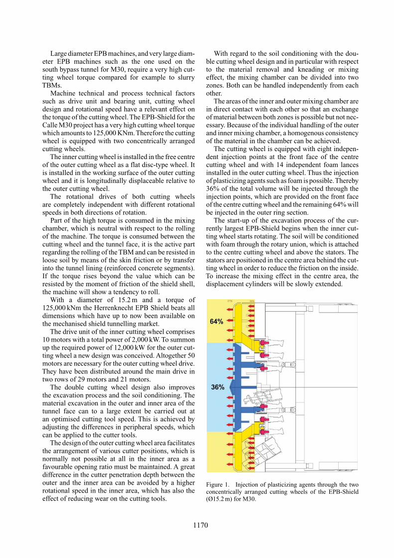
With regard to the soil conditioning with the dou-ble cutting wheel design and in particular with respectto the material removal and kneading or mixingeffect, the mixing chamber can be divided into twozones. Both can be handled independently from eachother.
The areas of the inner and outer mixing chamber arein direct contact with each other so that an exchangeof material between both zones is possible but not nec-essary. Because of the individual handling of the outerand inner mixing chamber, a homogenous consistencyof the material in the chamber can be achieved.
The cutting wheel is equipped with eight indepen-dent injection points at the front face of the centrecutting wheel and with 14 independent foam lancesinstalled in the outer cutting wheel. Thus the injectionof plasticizing agents such as foam is possible.Thereby36% of the total volume will be injected through theinjection points, which are provided on the front faceof the centre cutting wheel and the remaining 64% willbe injected in the outer ring section.
The start-up of the excavation process of the cur-rently largest EPB-Shield begins when the inner cut-ting wheel starts rotating. The soil will be conditionedwith foam through the rotary union, which is attachedto the centre cutting wheel and above the stators. Thestators are positioned in the centre area behind the cut-ting wheel in order to reduce the friction on the inside.To increase the mixing effect in the centre area, thedisplacement cylinders will be slowly extended.
Figure 1. Injection of plasticizing agents through the twoconcentrically arranged cutting wheels of the EPB-Shield(Ø15.2 m) for M30.
1170
It can be assumed that the soil will be well-conditioned up to a diameter of approximately 9 m andthis will considerably reduce the starting torque of theouter cutting wheel.
As soon as the centre area is conditioned, the outercutting wheel starts turning and simultaneously addingfoam. Thus, the complete excavation area will behomogeneously conditioned and the advance processcan commence.
The excavated material is transported out of theexcavation chamber via three screw conveyors, whichare integrated in the shield. They handle an excavatedvolume of 565 solid cubic meter per ring. There aretwo parallel screw conveyors (Ø1,250 mm), which arelocated in the lower part of the shield to remove theexcavated material from the outer cutting wheel andto transport it back to the belt conveyor. The third andsmallest screw conveyor (Ø600 mm) is arranged in thelower third of the central cutting wheel. It will removethe excavated material from this area and convey itback to the belt conveyor.
The complete transport of the TBM from the man-ufacturing factory to the jobsite took two months. Themain components of the Shield TBM were first trans-ported with a river boat to the port of Rotterdam andthen with two ships to Spain. For unloading the compo-nents a crawler crane with a capacity of 600 tons wasnecessary. The transport on the road lasted approxi-mately nine days (50 km per night accompanied bythe police).
The excavation of the 3,525 m long north tunnelof the south bypass on Madrid’s highway M30 startedon November 15, 2005 and could successfully be com-pleted, on July 12, 2006, by the team of the contractorsAcciona Infraestructuras S.A. and Ferrovial-AgromanS.A. in cooperation with Herrenknecht AG, after only8 months of construction time.
During advance the giant boring machine achievedconvincing performances, which could be increasedweek by week and pushed to a best weekly perfor-mance of 94 rings or 188 m. The best daily perfor-mance amounted to 18 rings or 36 m and the strongestmonthly performance could be reached in May 2006with considerable 758 m.
After the assembly and learning phase, weekly per-formances, which were clearly higher than 50 rings or100 m, could be achieved permanently. The tunnellingcycles were 30 minutes and the construction of a ring,consisting of 10 concrete segments, 13.9 tonnes each,could be carried out in approx. 50 minutes. Duringtunnelling a cycle time of less than 100 minutes couldbe achieved for the advance and the installation of a2,000 mm long ring.TheTBM supplier’s and construc-tion firms’ skilled personnel helped to reduce learningcurve effects.
After approx. 1,000 m, 2,000 m and 3,000 m oftunnelling, a standstill of approx. 4 days was each
scheduled in order to inspect the cutting tools, installtunnel belt boosters and carry out other maintenanceoperations that could not be done parallel to theadvance. The target construction time of 12 monthscould clearly be underrun, and the 8-month tunnel con-struction time equals an excellent TBM performanceof more than 450 m per month.
3 LARGEST MIXSHIELD (Ø15.4 M)IN OPERATION IN SHANGHAI
With the construction of the gigantic project “ShanghaiChangxing Under River Tunnel” the region of theYangtze delta near Shanghai will be further opened.
The Yangtze is Chinas biggest river. Its yearly flowof 951.3 billion cubic metres of water amounts toapprox. 52% of the total yearly quantity of all Chineserivers.
The greatest challenge of this project is the connec-tion of the two river banks from the Pudong mainlandwith the island of Chongming. Two parallel motor-way tunnels with a length of 8,950 m each will bebuilt between the mainland Pudong and the islandof Changxing. A bridge will connect the island ofChangxing with the island of Chongming.
Since the waterway between the mainland Pudongand the island Changxing is a very busy main shippingroute, the tunnel solution was preferred instead of abridge construction.
With a length of 80 km and a width of 20 km,Chongming is the third biggest island of China. Theisland Changxing with a population of about 30,000 ischaracterised by the establishment of industries withthree large shipping services.
The two parallel tunnels will run beneath the largestriver of China with the currently largest two tunnelboring machines. The Mixshields have a shield diam-eter of 15.43 m. Each of the tunnel tubes will integratetwo levels, of which the upper level will contain threelanes for motor traffic and the lower level is plannedto integrate a rescue lane in the centre and a safetypassage.
The planned construction period of the ChongmingYangtze River CrossingTunnel near Shanghai amountsto four years.
The challenges for the design of the two largestMixshields for the river crossing were on the one handthe large shield diameter of 15.43 m and on the otherhand the predicted geological and hydrological condi-tions. Each tunnel will have a total length of approx.7,170 m with a gradient of ±2.9%.
The two Mixshields are adapted to the local geo-logical and hydrological conditions featuring clayeyformations and very high groundwater pressures. Theentire tunnel will be built in very weak, clayey soilsbelow the groundwater table. Characteristic of the
1171
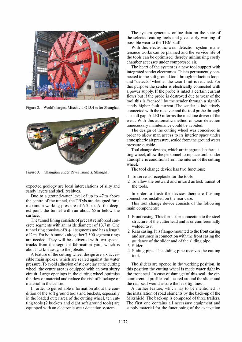
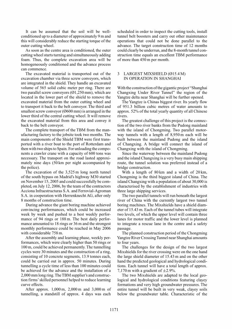
Figure 2. World’s largest Mixshield Ø15.4 m for Shanghai.
Figure 3. Changjian under River Tunnels, Shanghai.
expected geology are local intercalations of silty andsandy layers and shell residues.
Due to a ground-water level of up to 47 m abovethe centre of the tunnel, the TBMs are designed for amaximum working pressure of 6.5 bar. At the deep-est point the tunnel will run about 65 m below thesurface.
The tunnel lining consists of precast reinforced con-crete segments with an inside diameter of 13.7 m. Onetunnel ring consists of 9 + 1 segments and has a lengthof 2 m. For both tunnels altogether 7,500 segment ringsare needed. They will be delivered with two specialtrucks from the segment fabrication yard, which isabout 1.5 km away, to the jobsite.
A feature of the cutting wheel design are six acces-sible main spokes, which are sealed against the waterpressure.To avoid adhesion of sticky clay at the cuttingwheel, the centre area is equipped with an own slurrycircuit. Large openings in the cutting wheel optimisethe flow of material and reduce the risk of blockage ofmaterial in the centre.
In order to get reliable information about the con-dition of the soft ground tools and buckets, especiallyin the loaded outer area of the cutting wheel, ten cut-ting tools (2 buckets and eight soft ground tools) areequipped with an electronic wear detection system.
The system generates online data on the state ofthe selected cutting tools and gives early warning ofpossible wear to the TBM staff.
With this electronic wear detection system main-tenance works can be planned and the service life ofthe tools can be optimised, thereby minimising costlychamber accesses under compressed air.
The heart of the system is a new tool support withintegrated sender electronics.This is permanently con-nected to the soft ground tool through induction loopsand “detects” whether the wear limit is reached. Forthis purpose the sender is electrically connected witha power supply. If the probe is intact a certain currentflows but if the probe is destroyed due to wear of thetool this is “sensed” by the sender through a signifi-cantly higher fault current. The sender is inductivelyconnected with the receiver and the tool probe througha small gap. A LED informs the machine driver of thewear. With this automatic method of wear detectionunnecessary maintenance could be avoided.
The design of the cutting wheel was conceived inorder to allow man access to its interior space underatmospheric air pressure, sealed from the ground waterpressure outside.
Tool change devices, which are integrated in the cut-ting wheel, allow the personnel to replace tools underatmospheric conditions from the interior of the cuttingwheel.
The tool change device has two functions:
1 To serve as receptacle for the tools.2 To allow the outward and inward airlock transit of
the tools.
In order to flush the devices there are flushingconnections installed on the rear case.
This tool change device consists of the followingmain components:
1 Front casing. This forms the connection to the steelstructure of the cutterhead and is circumferentiallywelded to it.
2 Rear casing. It is flange-mounted to the front casingand assumes in connection with the front casing theguidance of the slider and of the sliding pipe.
3 Slider.4 Sliding pipe. The sliding pipe receives the cutting
tool.
The sliders are opened in the working position. Inthis position the cutting wheel is made water tight bythe front seal. In case of damage of this seal, the cir-cumferential profile seal located around the slider andthe rear seal would assure the leak tightness.
A further feature, which has to be mentioned, isthe installation of road elements by the back-up of theMixshield. The back-up is composed of three trailers.The first one contains all necessary equipment andsupply material for the functioning of the excavation
1172
process. The second trailer is a bridge construction toallow free space of ±20 m for placing the road ele-ments, which are precast concrete parts of 2 m lengthin dimension, 4.30 m in width and 4.56 m in height.Each element has a weight of approx. 35 tons.
Supplies will be delivered to the TBM with trucks.They will drive along these rectangular road elementswhich are placed along the centre of the bottom ofthe tunnel. The trucks will be unloaded in the back-uptrailer number 3.
Back-up number 1 will run on invert slabs. Theseare placed on the already built segment ring and willbe taken out and moved to the front as soon as thefirst back-up trailer passed this section. Back-up trailernumber three runs on auxiliary rails.
The tunnel excavation for the about 7,170 m per tun-nel tube is expected to take about 34 months. The com-missioning of the BOT-tunnels is planned for 2010.
4 CONCLUSION
The two cited Shield TBM projects are characteristicof demanding conditions like the under river crossing
near Shanghai and the inner-city tunnelling for theM30 project in Madrid. Both projects illustrate thefeasibility of large diameter tunnels and are pointingthe way for future projects regarding the excavation ofeven larger tunnel cross sections, long-distance boredtunnels and even deeper excavations.
In general, it is important to have a good under-standing of all the conditions of a project already inthe planning stage. The geological information is ofparticular interest because the machine design will beadapted to the predicted geological conditions. It isincreasingly important to avoid possible risks whentunnelling in urban areas and also in the open countrywhen underpassing existing structures or rivers and tofurther adapt the technology to make it even more safeand efficient.
1173


![ISSN 2339-0638 - IRGSCirgsc.org/pubs/wp/IRGSCWP008-climate-smart-agriculture.pdf · 2014-03-26 · 1 IRGSC Working Paper Series - WP 8 [] ISSN 2339-0638 ISSN 2339-0638 Impact of Climate](https://img.pdfslide.net/doc/110x75/5f601a46420b39090f45f1cd/issn-2339-0638-2014-03-26-1-irgsc-working-paper-series-wp-8-issn-2339-0638.jpg)