Embed Size (px)
Citation preview
10 04|2007 www.mcadonline.com
SOFTWARE REviEW UGS NX 5
UGS NX 5
ÓThe NX user interface has undergone a lot of changes over the past five releases, each aimed at
making the system more and more accessible, so users can discover new functionality without having to resort to manuals or other training materials. NX 5 continues this trend with some impressive developments.
The development team has broken down every com-mand into its constituent parts (or blocks) then used those common blocks to build workflow-oriented command dialogs that guide the user through each operation. What this means is that now there is just one block for each input method, parameter assignment or option. In other systems (including previous releases of NX) you typically have a wide array of inputs for every feature, but the manner in which you use them differs between each command. UGS has rationalised these differences and the result is a system in which you learn a task once (perhaps selecting geometry, assigning limits etc) then reuse that knowledge in every other command you come across that uses that same input.
But it doesn’t stop there, the Block-based dialogs are combined with two other new UI features. Firstly, the dialogs themselves are now organised into workflows (using these blocks) and you have a huge amount of feedback about the process you’re working on. Dialogs present the most com-monly used options for a command, so you can build basic features very quickly. If you need to access the more advanced options and parameters then you simply click the appropriate section of the dialog - it expands and you provide the inputs required. These new dialogs also feature a huge amount of feedback about the specific task you’re doing, using colours and other graphic tricks to show when all the required inputs are complete, or perhaps, more importantly, when they’re not.
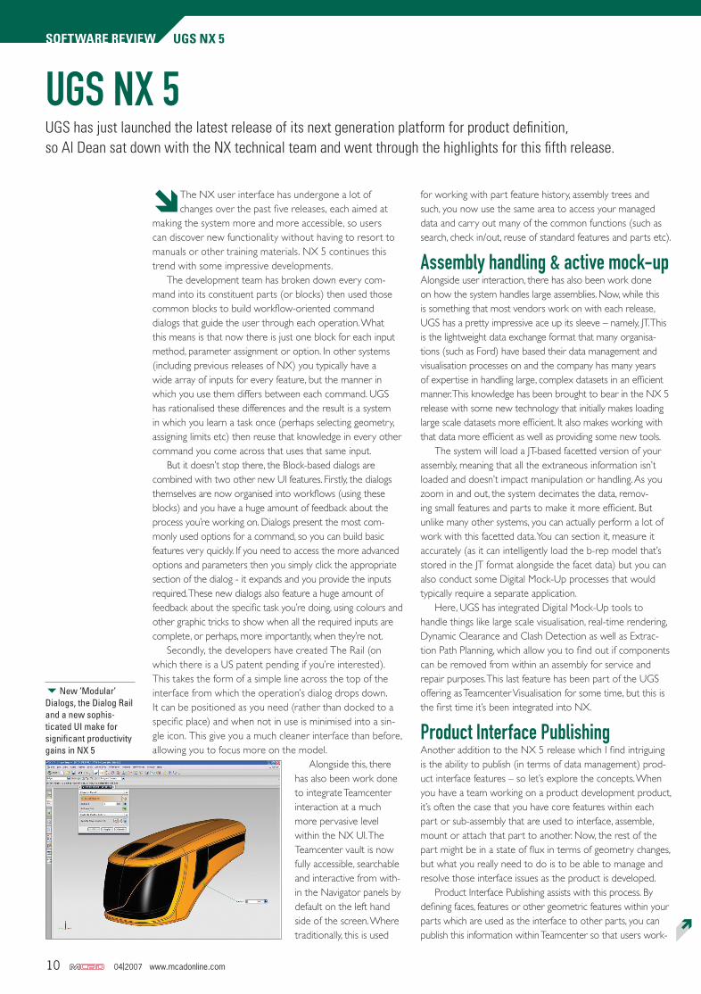
Secondly, the developers have created The Rail (on which there is a US patent pending if you’re interested). This takes the form of a simple line across the top of the interface from which the operation’s dialog drops down. It can be positioned as you need (rather than docked to a specific place) and when not in use is minimised into a sin-gle icon. This give you a much cleaner interface than before, allowing you to focus more on the model.
Alongside this, there has also been work done to integrate Teamcenter interaction at a much more pervasive level within the NX UI. The Teamcenter vault is now fully accessible, searchable and interactive from with-in the Navigator panels by default on the left hand side of the screen. Where traditionally, this is used
for working with part feature history, assembly trees and such, you now use the same area to access your managed data and carry out many of the common functions (such as search, check in/out, reuse of standard features and parts etc).
Assembly handling & active mock-upAlongside user interaction, there has also been work done on how the system handles large assemblies. Now, while this is something that most vendors work on with each release, UGS has a pretty impressive ace up its sleeve – namely, JT. This is the lightweight data exchange format that many organisa-tions (such as Ford) have based their data management and visualisation processes on and the company has many years of expertise in handling large, complex datasets in an efficient manner. This knowledge has been brought to bear in the NX 5 release with some new technology that initially makes loading large scale datasets more efficient. It also makes working with that data more efficient as well as providing some new tools.
The system will load a JT-based facetted version of your assembly, meaning that all the extraneous information isn’t loaded and doesn’t impact manipulation or handling. As you zoom in and out, the system decimates the data, remov-ing small features and parts to make it more efficient. But unlike many other systems, you can actually perform a lot of work with this facetted data. You can section it, measure it accurately (as it can intelligently load the b-rep model that’s stored in the JT format alongside the facet data) but you can also conduct some Digital Mock-Up processes that would typically require a separate application.
Here, UGS has integrated Digital Mock-Up tools to handle things like large scale visualisation, real-time rendering, Dynamic Clearance and Clash Detection as well as Extrac-tion Path Planning, which allow you to find out if components can be removed from within an assembly for service and repair purposes. This last feature has been part of the UGS offering as Teamcenter Visualisation for some time, but this is the first time it’s been integrated into NX.
Product Interface PublishingAnother addition to the NX 5 release which I find intriguing is the ability to publish (in terms of data management) prod-uct interface features – so let’s explore the concepts. When you have a team working on a product development product, it’s often the case that you have core features within each part or sub-assembly that are used to interface, assemble, mount or attach that part to another. Now, the rest of the part might be in a state of flux in terms of geometry changes, but what you really need to do is to be able to manage and resolve those interface issues as the product is developed.
Product Interface Publishing assists with this process. By defining faces, features or other geometric features within your parts which are used as the interface to other parts, you can publish this information within Teamcenter so that users work-
UGS has just launched the latest release of its next generation platform for product definition, so Al Dean sat down with the NX technical team and went through the highlights for this fifth release.
6New ‘Modular’ Dialogs, the Dialog Rail and a new sophis-ticated UI make for significant productivity gains in NX 5
Ï
10,11,13,15 MCAD 04-07 NX5.indd 10 17/4/07 12:33:25
www.mcadonline.com 04|2007 11
UGS NX 5 SOFTWARE REviEW
ing on related parts or sub-assemblies are aware of design changes made to those critical features. This means you get the usual notifications of mods, and revision controls those features specifically. Also, you have the ability to use those core features and lock any assembly mating work to just use those features. This means that parts have to be mounted in the way you require, which removes a massive potential for error. In these days of contract engineers, who may not have higher-level understanding of your products, this is pretty bloody useful.
The Interfaces are stored within the part tree and are immediately available. Also, because you’re building this information into the core of your product, you can use that for queries by running ‘where used’ searches and the like, so the effects of modification of those critical features can be investigated with ease – something that you typically couldn’t do to at such a granular level.
Direct modellingIf there’s been an emerging trend within the product develop-ment technology industry in the past year or so, it has to be the adoption of direct modelling techniques. It seems that whatever press event I attend, I’m having the benefits of non-history-based modelling thrown at me from all directions. Some of this is from vendors already active within that space (IronCAD and of course, the direct modelling stalwart, CoCreate), but also from those with a heavy reliance on history-based approach offering an extension of their existing technology which looks to address the problems inherent with their own technology. There’s even a new entrant into the market with the forth-coming release of SpaceClaim as we covered briefly last month. What I’ve come to realise is that every vendor is approaching the problem of making design mods without recourse to a history tree (whether that’s native data or otherwise) slightly differently, so what can NX do and how does it do it?
There are four basic direct modelling operations introduced within NX 5. Move Face, Offset Region, Resize Blend and Delete Faces. I’m going to talk about the general concepts involved first, then look at each in more detail. In general, there’s been a lot of work done to make the selection of ‘geometric features’ more intelligent – and in this context, I mean a feature in terms of a group of geometry that describes a design or manufacturing feature, rather than an entry in the history tree.
Some systems with a history in this field (no pun intended) have always failed to make the selection of geometry an easy process. This is because you aren’t relying on feature-data to define the scope of a selection, so much of it involves manual selection, which for some features can be a tricky process (particularly when dealing with imported geometry). What UGS has done is provide a list of selection types to help narrow down the process. These range from Single or Multiple Faces, can include propagation of selec-tion to tangent faces (such as connected by a fillet), but also extend into recognising of features such as Ribs, Slots, and the most powerful, Boss or Pocket faces. The way each works is different and essentially relies on the presets defining how a system connects faces into a single feature. For example, selecting elements using the boss or pocket feature will find all of the faces within a single enclosed boundary. From what I have seen UGS has managed to implement this very well, although I’m sure that non-native data will always throw up
a few problems which mean you have to select geometry individually with the control key selected as per normal.
The Move Face command is probably the most powerful and despite the name, allows several things to happen. You can move faces by a distance between two points, or you can rotate them about one or two axes. Whichever operation you choose, you define the geometry you want to work with using the tools we’ve discussed, then select a reference. This might a global UCS based direction (X, Y or Z), a geometry reference (such as an edge for translation or a cylindrical face or axis for rotation). You then use dynamic handles to drag that feature into the new position. A dynamic graphic preview is shown, so you have a good idea if your feature is going to work (if it isn’t, it won’t display).
Another Direct Modelling command is Resize Blend. This, as you might expect, allows you to select a blend (or fillet if you like) and edit the radius. The Offset region command is pretty self explanatory. You select a set of faces and the system will create an offset, extend and trim the underlying faces and end conditions then create a replacement feature which scales up or down that face set. Again, this feature will also adjust non-off-set tangent faces, so your fillets are maintained where possible. If they are not, you can recreate them once you’ve deleted them using the Delete Faces command – which leads me nicely onto the next feature. The fourth direct modelling command is the Delete Faces operation. Again, it’s pretty self explanatory as it allows you to delete a face and if possible, have the system rebuild the underlying geometry by extending/re-trimming or just removing the appropriate boundaries within a surface set.
These are the basic Direct Modelling commands and I’m sure each has its own limitations. For example, you can only move a feature within the boundaries of the originat-
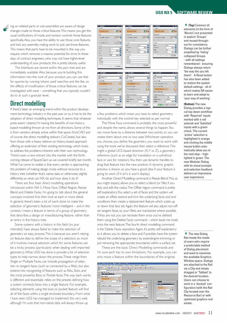
3(Top) Common UI elements (in the form of ‘Blocks’) are presented in explicit ‘Groups’ and reused through-out for consistency. Dialogs can be further simplified by ‘hiding’ collapsed Groups - with all settings remembered - ensuring Dialogs always return ‘the way the you left them!’. A Reset button has also been added to restore the system default settings - all of which makes NX easier to learn and adopt to ‘your way of working’.
(Bottom) The new Dialog provides a logi-cal top-down workflow with ‘Required’ inputs marked with a red asterisk and ‘Satisfied’ inputs with a green check. The current ‘active’ selection is highlighted in orange and clicking the middle mouse button auto-matically takes you to the next step – high-lighted in green. The new Modular Dialog with its visual prompts and selection feedback delivers an impressive user experience.
3The new Dialog Rail meets the needs of users who require a predictable method of Dialog placement and want to maximise the available Graphics Window space. Dialogs are attached to the Rail via a Clip and simply dragged or ‘Tabbed’ to the desired location. Users can choose to work in a ‘docked’ con-figuration (with the Rail Clip located over the Resource Bar) or with optimised graphics real estate.
Ï
10,11,13,15 MCAD 04-07 NX5.indd 11 17/4/07 12:33:27
www.mcadonline.com 04|2007 13
UGS NX 5 SOFTWARE REviEW
ing surface into which it’s built - you can’t typically do that in other systems either, it’s just how geometry and topol-ogy changes are handled.
What is very interesting is that rather than just allowing you to make the change in a non-intelligent manner, NX adds that change you make and the options you defined as a formalised feature onto the end of the history tree. What this means is that you get the best of both worlds. You get the ability to make edits to a part without concerns about the history, but then take advantage of history to allow you to make further edits to that feature if needs be. If you want to learn more about the whole concept, I’m currently writing a feature on the subject for a forthcoming issue, so stay tuned.
Requirement Driven Design ValidationThe last area I want to concentrate on is a new area for NX and I personally haven’t seen this type of technology from any other vendor. It deals with an interesting problem within a 3D-led product development environment and that revolves around the fact that a product is typically driven by a set of User or Customer Requirements. These are typically abstract needs or preferences that don’t lend themselves to a 3D data model. What I mean by this is that they are inputs to the design process that are outside of the immediately quantifiable mechanical or dimensional inputs (such as size, performance, strength etc). So, if you’re looking to have a 3D-centric product model that encapsulates everything about that product, how do you go about integrating these into the 3D dataset?
UGS has linked the Requirement Management tools within Teamcenter to the NX modelling tools. This allows you to create an intelligent link between the sometimes esoteric inputs to the 3D model. Those that have studied and implemented Taguchi methods will understand what I’m talking about – if you
carry through the process, you’ll find that with a bit of lateral thought, you can always quantify the initially unquantifiable. For example, a user may require that a product can handle tough working conditions – these can be linked to mechanical struc-tural strength, materials definitions. Once the link has been es-tablished, during the design cycle the system can create a series of checks that link the two closer, so that design changes are evaluated on the basis of user requirements. These might be measurements, mass properties, results of analysis or simulation or a custom check built on the knowledge-based engineering or design rules (expressions) technology available in NX. This is an integral part of the update cycle, so the checks (stored in the Checks folder in the part structure) are run as you make modifications. Of course, you don’t have to have Teamcenter Requirements to do this, you can integrate the check purely at a 3D model level, but it really sings when you link the two.
In conclusionThe UI work that the team has done is incredible. Regular MCAD readers will know that this is something I have great deal of belief in. After all, User Interaction is something that affects every user of every product and if done correctly, the usage model for any system can be made so much more efficient through some very simple and subtle changes to the UI. The blocks-based dialog approach makes a great deal of sense, but combined with the workflow-led presentation methods and a large amount of feedback it means that you learn how to do a task just once and that knowledge is then retained and reused in every single instance – removing ambiguity and maximising retention of knowledge and the time you invest in learning. All of this is sure to make both the power and casual user more efficient in their daily tasks. UGS claims that the new user can learn the basics of NX in a
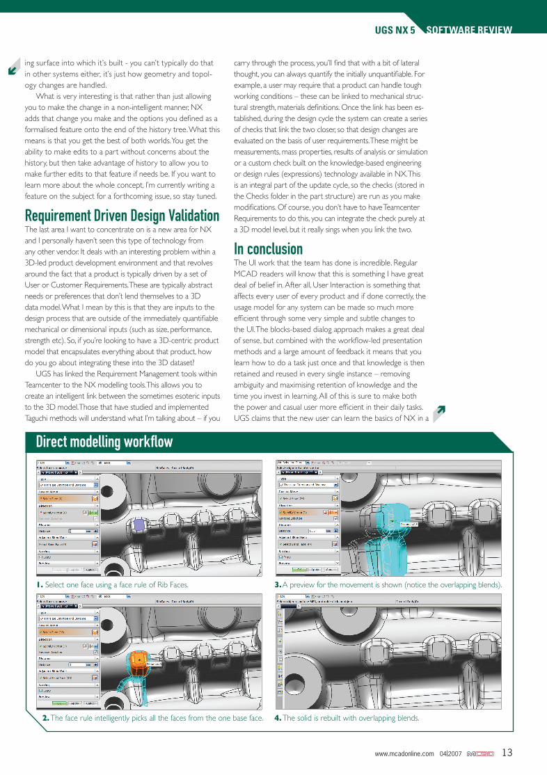
Direct modelling workflow
1. Select one face using a face rule of Rib Faces.
2. The face rule intelligently picks all the faces from the one base face.
3. A preview for the movement is shown (notice the overlapping blends).
4. The solid is rebuilt with overlapping blends.
Ï
Ï
10,11,13,15 MCAD 04-07 NX5.indd 13 17/4/07 12:35:03