Embed Size (px)
Citation preview

H
O
Solar Concentrating and Storage Architectonics
Joel H. Goodman
PROGRESS PRINT
December 30, 2013
a b c d
e
j k
f
i
g h
l
m n o p
PARTIAL COPY OF BOOK
Solar Concentrating and Storage Architectonics Joel H. Goodman December 30, 2013
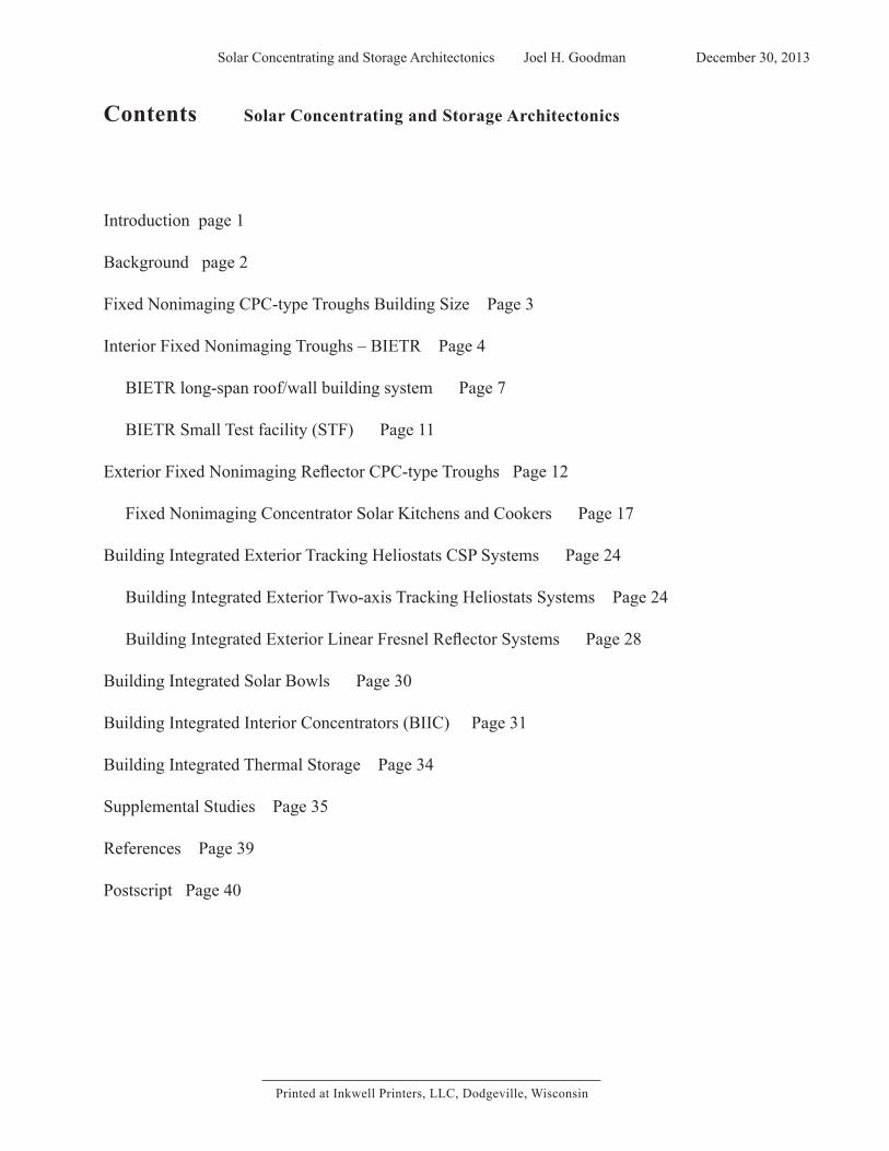
Contents Solar Concentrating and Storage Architectonics
Introduction page 1
Background page 2
Fixed Nonimaging CPC-type Troughs Building Size Page 3
Interior Fixed Nonimaging Troughs – BIETR Page 4
BIETR long-span roof/wall building system Page 7
BIETR Small Test facility (STF) Page 11
Exterior Fixed Nonimaging Reflector CPC-type Troughs Page 12
Fixed Nonimaging Concentrator Solar Kitchens and Cookers Page 17
Building Integrated Exterior Tracking Heliostats CSP Systems Page 24
Building Integrated Exterior Two-axis Tracking Heliostats Systems Page 24
Building Integrated Exterior Linear Fresnel Reflector Systems Page 28
Building Integrated Solar Bowls Page 30
Building Integrated Interior Concentrators (BIIC) Page 31
Building Integrated Thermal Storage Page 34
Supplemental Studies Page 35
References Page 39
Postscript Page 40
Printed at Inkwell Printers, LLC, Dodgeville, Wisconsin

Solar Concentrating and Storage Architectonics Joel H. GoodmanDecember 30, 2013
Solar Concentrating and Storage Architectonics
Joel H. Goodman
Solar Concentrating and Storage Architectonics (SCSA) is a compilation of studies expanding from the 1993 Solar Concentrating Architectonics (SCA) publication. Building integrated active solar concentrating collector and storage studies have been added to include: fixed nonimaging reflector building size troughs (exterior and interior); one and two axis tracking heliostat systems; storages, tanks for the most part; interior imaging concentrators; and combinations of collectors and storages, complementing the solar bowl and beginning of building interior concentrators studies in the 1993 work. This work in progress, a pre-book outline, is intended to be a preparation for an expanded and more complete publication. Included are: historical background, associated research and development issues, and references/bibliographies.
Joel H. GoodmanPost Office Box 14 Dodgeville
Wisconsin 53533 [email protected]
www.PVO-Pergolas.com
CSP Bird

Solar Concentrating and Storage Architectonics Joel H. Goodman December 30, 20131
Fig. 1- Solar Concentrating and Storage Architectonics Introduction: 1.1 Building integrated concentrators and storage diagrams; 1.2 Collector coverage; 1.3 Building integrated schematics; 1.4 Exterior glazing aperture (EGA) types.
INTRODUCTION
This report contains architectonic studies with building integrated active concentrating (imaging and nonimaging) sunlight collector and storage technology systems independent of architectural idioms and building styles. The method has been to begin with the active solar energy technologies and to search for fitting and harmonious architectural structures and forms related to global regional characteristics (solar energy resource, climate, dust, etc.) in consonance with passive design and efficiency measures to reduce off-site imported energy demand. The conventional building design approach for energy has been and still is for the most part with electric grid wires and natural gas pipelines which surely provide flexibility for building designers, whereas greater dependence on building integrated active solar energy requires solar access and substantially influences conceptual building design and site planning. Solar reflecting concentrators have been mainly used for thermal applications, and for concentrator photovoltaics (CPV), and also combined solar thermal- PV technologies are being developed. The presented active solar concentrating architectonic schematic studies are general concentrator configurations for existing collector technology targets and for future collector technologies likely to continually improve. The solar reflector optical concentration configurations are expected to be relevant for far longer than the availability of affordable fossil fuels with the estimated approximate 5 billion sunlit years remaining for the Earth’s sun.
Durable buildings, landscaping, and planning designs implemented today can be in place for over 100 years. Architecture and urban designs without inclusion of active solar energy technologies, delay a required wider reformation, and associated learning-curve. Passive design and efficiency advances alone may be misleading if structural changes to buildings and site planning patterns for active solar renewable energy are ignored. The opportunity for incremental development over a long period of time toward post fossil fuel sustainability is blocked by continued development of fossil fuel dependent forms. Buildings and cities have only so much area for solar collectors and on-site renewable energy facilities. And active solar technologies need to be understood and considered at the beginning of programming and conceptual design stages. Large arrays of active solar collectors and large solar energy storages are substantial design elements which are structure and form generating influences. Aims for these studies have been to search for aesthetic collector and storage schematics that may be included in architectural designs,
and to stimulate interest for inclusion in architectural education curriculums.
Solar Concentrating and Storage Architectonic Studies include: Exterior fixed nonimaging troughs; Interior fixed nonimaging troughs (BIETR); Two-axis tracking small heliostats with central receiver; One-axis tracking long-span linear Fresnel heliostat reflectors with linear receivers; Spherical segment imaging fixed reflector bowl with two-axis tracking linear receiver; Interior tracking collectors; Storage tanks building integrated; and Combinations of collectors and storage. A few studies are with reused wind blades as building structures (beams and columns).
1.
2.
3.
4.
a) b) c)

Solar Concentrating and Storage Architectonics Joel H. Goodman December 30, 20133
Fig. 3 – Fixed Nonimaging Trough Shapes: a) one sided CPC; b) ordinary CPC; c) asymmetric CPC; d) involute; e) split involute; f) “sea shell”; g) “sea shell” plus; h) matched vertical outlets; i) vertical outlet; j) close packed troughs; k) adjustable CPC sides; l) E-W line troughs; m) adjustable/tracking end reflectors; n) N-S line inclined trough
Fig. 2 – Building-size integrated nonimaging (NI) CPC-type concentrating reflector fixed trough configurations: a) exterior troughs; b) interior troughs; c) combined exterior and interior NI troughs.
Fixed Nonimaging CPC-type Troughs
Fixed nonimaging (NI) CPC type concentrating reflector troughs have solar radiation inlet aperture acceptance angles and fixed outlet apertures for collector-receivers (cookers, evacuated tubes, etc.). Compound parabolic concentrator (CPC) is a general term used to describe several types of NI concentrator shapes. NI fixed reflector troughs concentrate the beam and some of the diffuse solar radiation entering the CPC trough acceptance angles with relaxed construction tolerances and very small efficiency losses (37). Truncation options provide building design flexibility.
NI trough shapes include: ordinary CPC (38), one-sided CPC, asymmetrical CPC, “sea shell” (21), cusp-involute (2). And fixed troughs have adjustable/tracking end reflector options to let the solar radiation in one end, and usefully reflect at the other end avoiding spillage. Troughs are positioned mostly in EW lines, with NS inclined possibilities (Fig. 3). CPC troughs with adjusted side reflector positions termed seasonal repositioning (SR) have an overall wider trough width. The fixed NI concentrating reflector
shapes are integrated with architectonic form and structural configurations.
Building integrated fixed NI CPC type trough studies are presented in two main sections: exterior troughs and interior troughs; and exterior and interior troughs can be combined (Fig. 2). Exterior NI fixed troughs are uncovered, without a glazing-roof, and are for regions without snow accumulation, and inclined for lower latitude regions such as the Tropics. For example, a trough near the equator would be inclined more vertically so that the inlet aperture plane would be nearly horizontal.
Interior NI fixed troughs are covered with a glazing and are for regions with snow accumulation. For example, the Building Interior Evacuated Tubes and Reflectors (BIETR) has a monolithic tempered glass cover-roof (Page 4).
Computer models have been developed with tested results indicating high efficiencies with relaxed trough construction tolerances. A Kreith and Kreider mathematical computer model accurately predicted CPC performance of CPC field testing at Argonne National Laboratory, Chicago, c1975 (39)(40). Hour-to-hour annual computer simulation modeling of ± 35 deg. CPCs with ±10 deg. misalignment had less than 3% loss for Phoenix, Boston and Miami (37).
a) b) c)
Solar Concentrating and Storage Architectonics Joel H. GoodmanDecember 30, 2013 4
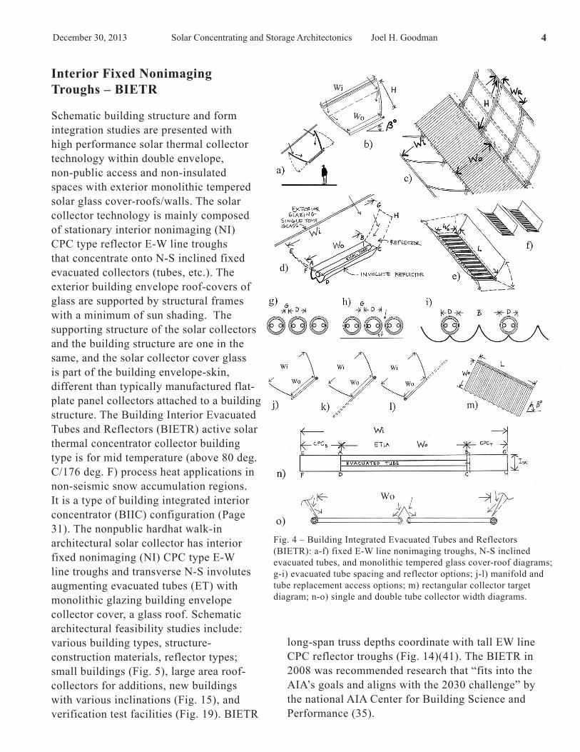
o)Fig. 4 – Building Integrated Evacuated Tubes and Reflectors (BIETR): a-f) fixed E-W line nonimaging troughs, N-S inclined evacuated tubes, and monolithic tempered glass cover-roof diagrams; g-i) evacuated tube spacing and reflector options; j-l) manifold and tube replacement access options; m) rectangular collector target diagram; n-o) single and double tube collector width diagrams.
Interior Fixed Nonimaging Troughs – BIETR Schematic building structure and form integration studies are presented with high performance solar thermal collector technology within double envelope, non-public access and non-insulated spaces with exterior monolithic tempered solar glass cover-roofs/walls. The solar collector technology is mainly composed of stationary interior nonimaging (NI) CPC type reflector E-W line troughs that concentrate onto N-S inclined fixed evacuated collectors (tubes, etc.). The exterior building envelope roof-covers of glass are supported by structural frames with a minimum of sun shading. The supporting structure of the solar collectors and the building structure are one in the same, and the solar collector cover glass is part of the building envelope-skin, different than typically manufactured flat-plate panel collectors attached to a building structure. The Building Interior Evacuated Tubes and Reflectors (BIETR) active solar thermal concentrator collector building type is for mid temperature (above 80 deg. C/176 deg. F) process heat applications in non-seismic snow accumulation regions. It is a type of building integrated interior concentrator (BIIC) configuration (Page 31). The nonpublic hardhat walk-in architectural solar collector has interior fixed nonimaging (NI) CPC type E-W line troughs and transverse N-S involutes augmenting evacuated tubes (ET) with monolithic glazing building envelope collector cover, a glass roof. Schematic architectural feasibility studies include: various building types, structure-construction materials, reflector types; small buildings (Fig. 5), large area roof-collectors for additions, new buildings with various inclinations (Fig. 15), and verification test facilities (Fig. 19). BIETR
long-span truss depths coordinate with tall EW line CPC reflector troughs (Fig. 14)(41). The BIETR in 2008 was recommended research that “fits into the AIA’s goals and aligns with the 2030 challenge” by the national AIA Center for Building Science and Performance (35).
Solar Concentrating and Storage Architectonics Joel H. Goodman December 30, 20137
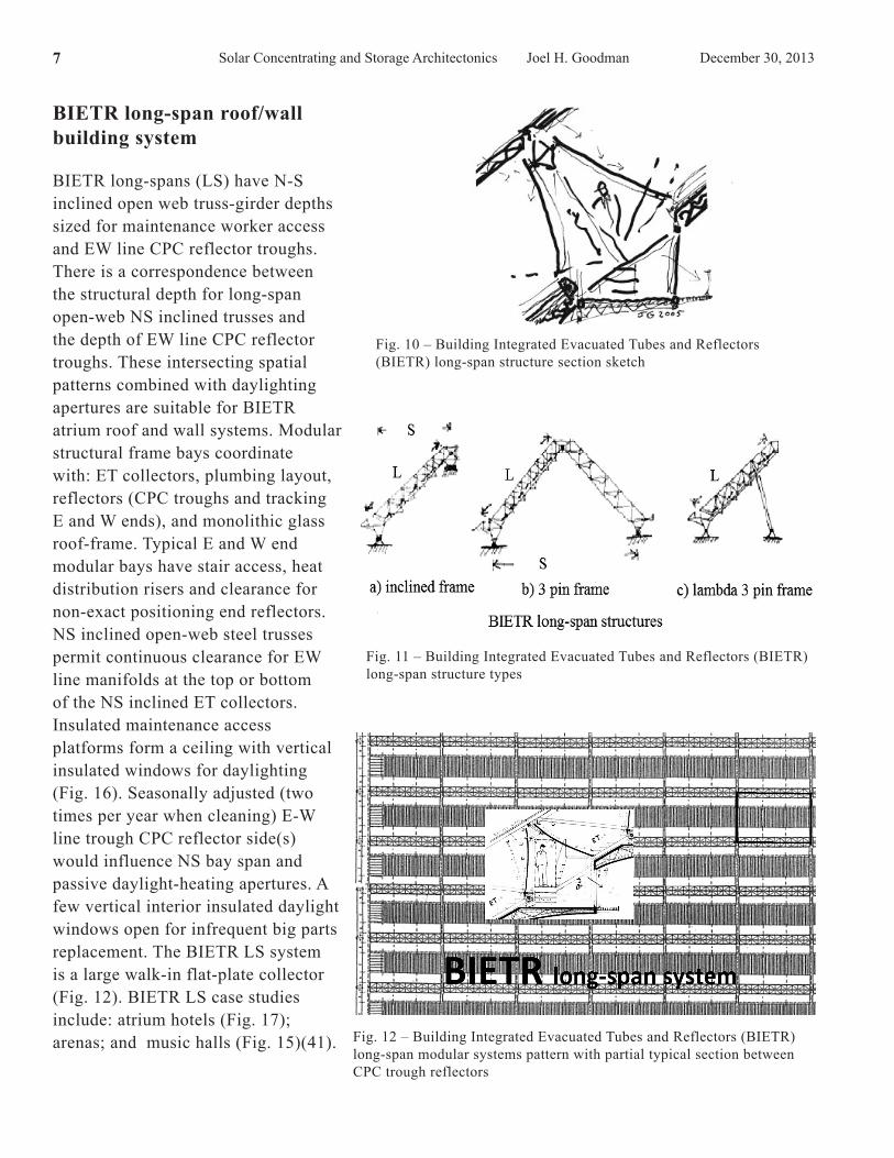
Fig. 10 – Building Integrated Evacuated Tubes and Reflectors (BIETR) long-span structure section sketch
Fig. 12 – Building Integrated Evacuated Tubes and Reflectors (BIETR) long-span modular systems pattern with partial typical section between CPC trough reflectors
Fig. 11 – Building Integrated Evacuated Tubes and Reflectors (BIETR) long-span structure types
BIETR long-span roof/wall building system
BIETR long-spans (LS) have N-S inclined open web truss-girder depths sized for maintenance worker access and EW line CPC reflector troughs. There is a correspondence between the structural depth for long-span open-web NS inclined trusses and the depth of EW line CPC reflector troughs. These intersecting spatial patterns combined with daylighting apertures are suitable for BIETR atrium roof and wall systems. Modular structural frame bays coordinate with: ET collectors, plumbing layout, reflectors (CPC troughs and tracking E and W ends), and monolithic glass roof-frame. Typical E and W end modular bays have stair access, heat distribution risers and clearance for non-exact positioning end reflectors. NS inclined open-web steel trusses permit continuous clearance for EW line manifolds at the top or bottom of the NS inclined ET collectors. Insulated maintenance access platforms form a ceiling with vertical insulated windows for daylighting (Fig. 16). Seasonally adjusted (two times per year when cleaning) E-W line trough CPC reflector side(s) would influence NS bay span and passive daylight-heating apertures. A few vertical interior insulated daylight windows open for infrequent big parts replacement. The BIETR LS system is a large walk-in flat-plate collector (Fig. 12). BIETR LS case studies include: atrium hotels (Fig. 17); arenas; and music halls (Fig. 15)(41).

Solar Concentrating and Storage Architectonics Joel H. Goodman December 30, 201311
Fig. 19 – BIETR Small Test Facility: a) S-N Section; b) Plan; c) reflectors key plan; d) reflector panel detail at top manifold; e) exterior glass frame schematic; f) glass installation sketch; g) glass sill detail at end reflector edge; h) access at end reflector; i) collector with tracking end reflectors; j) hinged end reflector connected to linkage; k) linear actuator driver.
Fig. 21 – BIETR small test models with light sensitive receiver plate or short evacuated tube collectors with water-steam or air manifolds.
BIETR Small Test Facility (STF)
A BIETR small test facility (STF) has a wood frame schematic plan around 14ft/4.26m x 16ft/4.87m with 5ft/1.5m long evacuated tube collectors. Four tempered low iron glass ¼ inch thick plates are supported on a steel glazing frame. Typical nonimaging CPC reflector trough wood frame panels are around 4ft x 5.5ft hinge-connected at a top wood header. Wood frame tracking flat trapezoidal end reflectors are connected by a cable above the collectors and driven with a controlled actuator (Fig. 19). Greenhouse building systems with corrugated polycarbonate glazing may be an option. BIETR small working test models with light sensitive receiver plate or short evacuated tube collectors with water-steam or air manifolds (Fig. 21) student projects have been written and are being offered to engineering education programs.
cable
Fig. 20 - BIETR Small Test Facility scale model photo
Solar Concentrating and Storage Architectonics Joel H. GoodmanDecember 30, 2013 12
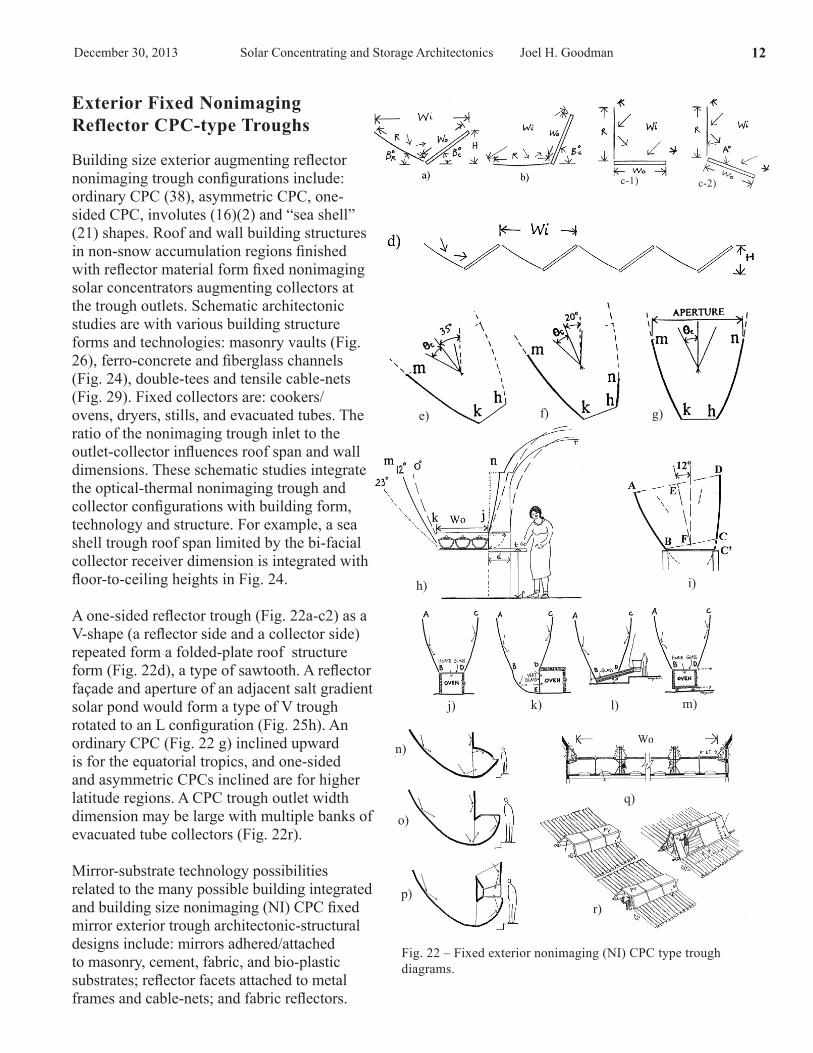
Fig. 22 – Fixed exterior nonimaging (NI) CPC type trough diagrams.
e) f) g)
h) i)
m)l)k)j)
p)
o)q)
n)
Exterior Fixed Nonimaging Reflector CPC-type Troughs
Building size exterior augmenting reflector nonimaging trough configurations include: ordinary CPC (38), asymmetric CPC, one-sided CPC, involutes (16)(2) and “sea shell” (21) shapes. Roof and wall building structures in non-snow accumulation regions finished with reflector material form fixed nonimaging solar concentrators augmenting collectors at the trough outlets. Schematic architectonic studies are with various building structure forms and technologies: masonry vaults (Fig. 26), ferro-concrete and fiberglass channels (Fig. 24), double-tees and tensile cable-nets (Fig. 29). Fixed collectors are: cookers/ovens, dryers, stills, and evacuated tubes. The ratio of the nonimaging trough inlet to the outlet-collector influences roof span and wall dimensions. These schematic studies integrate the optical-thermal nonimaging trough and collector configurations with building form, technology and structure. For example, a sea shell trough roof span limited by the bi-facial collector receiver dimension is integrated with floor-to-ceiling heights in Fig. 24.
A one-sided reflector trough (Fig. 22a-c2) as a V-shape (a reflector side and a collector side) repeated form a folded-plate roof structure form (Fig. 22d), a type of sawtooth. A reflector façade and aperture of an adjacent salt gradient solar pond would form a type of V trough rotated to an L configuration (Fig. 25h). An ordinary CPC (Fig. 22 g) inclined upward is for the equatorial tropics, and one-sided and asymmetric CPCs inclined are for higher latitude regions. A CPC trough outlet width dimension may be large with multiple banks of evacuated tube collectors (Fig. 22r).
Mirror-substrate technology possibilities related to the many possible building integrated and building size nonimaging (NI) CPC fixed mirror exterior trough architectonic-structural designs include: mirrors adhered/attached to masonry, cement, fabric, and bio-plastic substrates; reflector facets attached to metal frames and cable-nets; and fabric reflectors.
r)
c-1) c-2)
Solar Concentrating and Storage Architectonics Joel H. Goodman December 30, 201317
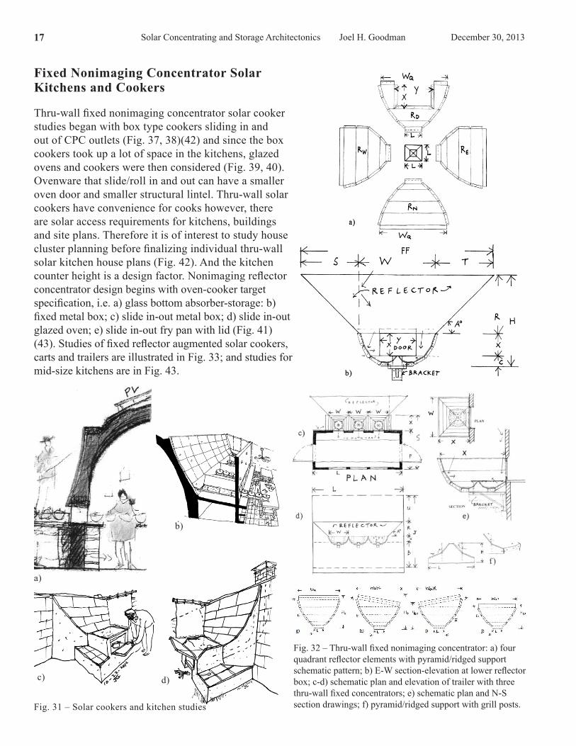
Fig. 32 – Thru-wall fixed nonimaging concentrator: a) four quadrant reflector elements with pyramid/ridged support schematic pattern; b) E-W section-elevation at lower reflector box; c-d) schematic plan and elevation of trailer with three thru-wall fixed concentrators; e) schematic plan and N-S section drawings; f) pyramid/ridged support with grill posts.Fig. 31 – Solar cookers and kitchen studies
Fixed Nonimaging Concentrator Solar Kitchens and Cookers
Thru-wall fixed nonimaging concentrator solar cooker studies began with box type cookers sliding in and out of CPC outlets (Fig. 37, 38)(42) and since the box cookers took up a lot of space in the kitchens, glazed ovens and cookers were then considered (Fig. 39, 40). Ovenware that slide/roll in and out can have a smaller oven door and smaller structural lintel. Thru-wall solar cookers have convenience for cooks however, there are solar access requirements for kitchens, buildings and site plans. Therefore it is of interest to study house cluster planning before finalizing individual thru-wall solar kitchen house plans (Fig. 42). And the kitchen counter height is a design factor. Nonimaging reflector concentrator design begins with oven-cooker target specification, i.e. a) glass bottom absorber-storage: b) fixed metal box; c) slide in-out metal box; d) slide in-out glazed oven; e) slide in-out fry pan with lid (Fig. 41)(43). Studies of fixed reflector augmented solar cookers, carts and trailers are illustrated in Fig. 33; and studies for mid-size kitchens are in Fig. 43.
a)
b)
c) d)
Solar Concentrating and Storage Architectonics Joel H. GoodmanDecember 30, 2013 24
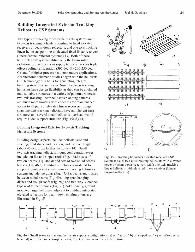
Fig. 45 – Tracking heliostats elevated receiver CSP systems: a,c,e) two-axis tracking heliostats with elevated tower or beam down receiver; b,d,f) one-axis tracking linear heliostats with elevated linear receiver (Linear Fresnel reflectors).
Fig. 46 – Small two-axis tracking heliostats support configurations: a) on flat roof; b) on sloped roof; c) set of two on a beam; d) set of two on a two-pole beam; e) set of two on an open-web 3d truss.
Building Integrated Exterior Tracking Heliostats CSP Systems
Two types of tracking reflector heliostats systems are: two-axis tracking heliostats pointing to fixed elevated receivers or beam-down reflectors; and one-axis tracking linear heliostats pointing to elevated fixed linear receivers (linear Fresnel reflector systems)(13). Both of these heliostats CSP systems utilize only the beam solar radiation resource, and can supply temperatures for triple effect cooling-refrigeration (392 deg. F / 200-250 deg. C), and for higher process heat temperature applications. Architectonic schematic studies began with the heliostats CSP technology as a basis for generating integral building structures and forms. Small two-axis tracking heliostats have design flexibility as they can be anchored onto suitable structures in a variety of patterns, whereas two-axis tracking linear heliostats planning patterns are much more limiting with concerns for maintenance access to all parts of elevated linear receivers. Long-span one-axis tracking heliostats have an inherent truss structure, and several small heliostats overhead would require added support structure (Fig. 45c,d)(44).
Building Integrated Exterior Two-axis Tracking Heliostats Systems
Building design aspects include: heliostat size and spacing, field shape and location, and receiver height (about 45 deg. from farthest heliostat)(14). Small two-axis tracking heliostats mount configuration types include: on flat and sloped roofs (Fig. 46a,b), sets of two on beams (Fig. 46c,d) and sets of two on 3d access trusses (Fig. 46 e). Building structures considered for supporting integrated small two-axis tracking heliostats systems include: pergolas (Fig. 47,48); beams and trusses between radial beams (Fig. 49); long-span hanging dishes and trough roofs (Fig. 50); and two-way Vierendel type roof terrace frames (Fig. 51). Additionally, ground mounted larger heliostats adjacent to building integrated elevated reflectors for beam-down configurations are illustrated in Fig. 53.
e) f)
a) b)
c) d)
Solar Concentrating and Storage Architectonics Joel H. GoodmanDecember 30, 2013 30
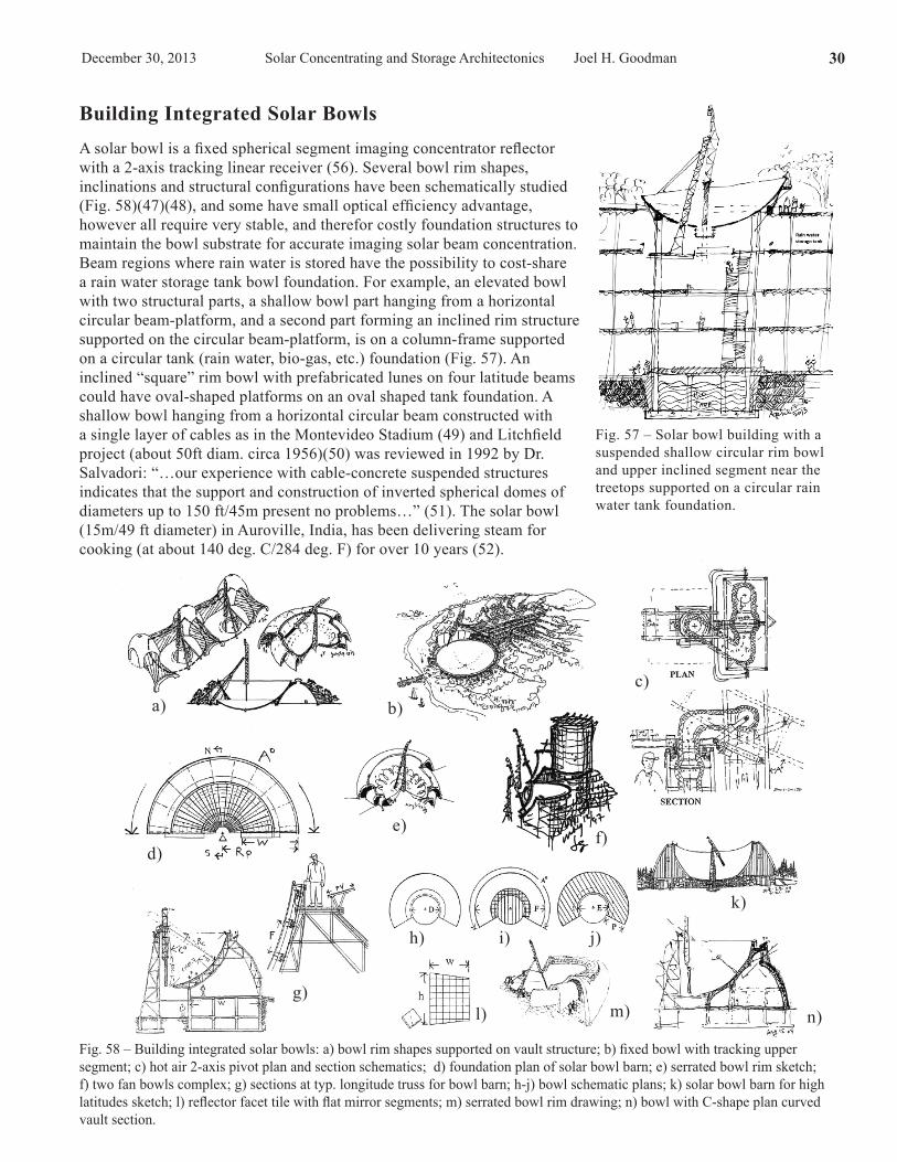
Fig. 57 – Solar bowl building with a suspended shallow circular rim bowl and upper inclined segment near the treetops supported on a circular rain water tank foundation.
Fig. 58 – Building integrated solar bowls: a) bowl rim shapes supported on vault structure; b) fixed bowl with tracking upper segment; c) hot air 2-axis pivot plan and section schematics; d) foundation plan of solar bowl barn; e) serrated bowl rim sketch; f) two fan bowls complex; g) sections at typ. longitude truss for bowl barn; h-j) bowl schematic plans; k) solar bowl barn for high latitudes sketch; l) reflector facet tile with flat mirror segments; m) serrated bowl rim drawing; n) bowl with C-shape plan curved vault section.
Building Integrated Solar Bowls A solar bowl is a fixed spherical segment imaging concentrator reflector with a 2-axis tracking linear receiver (56). Several bowl rim shapes, inclinations and structural configurations have been schematically studied (Fig. 58)(47)(48), and some have small optical efficiency advantage, however all require very stable, and therefor costly foundation structures to maintain the bowl substrate for accurate imaging solar beam concentration. Beam regions where rain water is stored have the possibility to cost-share a rain water storage tank bowl foundation. For example, an elevated bowl with two structural parts, a shallow bowl part hanging from a horizontal circular beam-platform, and a second part forming an inclined rim structure supported on the circular beam-platform, is on a column-frame supported on a circular tank (rain water, bio-gas, etc.) foundation (Fig. 57). An inclined “square” rim bowl with prefabricated lunes on four latitude beams could have oval-shaped platforms on an oval shaped tank foundation. A shallow bowl hanging from a horizontal circular beam constructed with a single layer of cables as in the Montevideo Stadium (49) and Litchfield project (about 50ft diam. circa 1956)(50) was reviewed in 1992 by Dr. Salvadori: “…our experience with cable-concrete suspended structures indicates that the support and construction of inverted spherical domes of diameters up to 150 ft/45m present no problems…” (51). The solar bowl (15m/49 ft diameter) in Auroville, India, has been delivering steam for cooking (at about 140 deg. C/284 deg. F) for over 10 years (52).
a) b)c)
d)e)
f)
g)
h) i) j)
k)
l) m) n)

Solar Concentrating and Storage Architectonics Joel H. Goodman December 30, 201331
Fig. 59 – Building Integrated Interior Concentrators (BIIC)- monolithic exterior glazing aperture (EGA) and frame configurations.
Building Integrated Interior Concentrators (BIIC)
The BIIC architectonic configurations have exterior monolithic high transmittance glazing-frame inlet apertures which are part of building envelopes (Fig. 59). The solar energy reflector concentrators (imaging and non-imaging) are within a non-insulated non-public collector utility space, forming a type of building double-envelope for roofs and walls, with daylighting possibilities. The interior envelope part of the roof or wall collector space is insulated. There are no wind, snow and ice loads and exterior soiling on the large area of lightweight reflectors. Reflector film on substrates is suitable for most of the interior concentrator architectonics.
Interior concentrating collector types include: a) one-axis tracking parabolic troughs (with tracking or fixed linear receivers); b) fixed nonimaging CPC type troughs [BIETR]; c) one-axis tracking reflector linear Fresnel; d) two-axis tracking heliostats; e) tracking Scheffler type heliostat with fixed receiver; and f) two-axis tracking dish-receiver (Fig. 60). The architectonic-structural configurations (horizontal and inclined) are fitting and expressive of the interior reflector concentrators (tracking and fixed), for example, fixed linear receivers hung from glass roof frames with linear Fresnel one-axis tracking reflectors, or one-axis tracking parabolic troughs on circular arc tracks (Fig.76a), would have different architectural characteristics. Selected exterior glazing configurations and concentrator types have been studied and developed into building form and structure architectonic schematics (Fig. 61-65). Small to large building type schematics include inclined and flat roofs (vaults, sawtooth
Fig. 60 – Building Integrated Interior Concentrators (BIIC) configuration diagrams: a) one-axis tracking parabolic troughs; b) fixed nonimaging CPC type troughs [BIETR]; c) one-axis tracking linear Fresnel; d) two-axis tracking heliostats; e) tracking Scheffler type heliostat with fixed receiver; f) two-axis tracking dish-receiver.
shapes, small domes), and sloped and vertical facades. Design aspects of reflector facet shapes and technology, and exterior and interior maintenance and washing access are being considered. Compatibility between the exterior glazing-frame form and exterior washing-access equipment is a design aim. Standalone large area horizontal interior one-axis tracking parabolic trough fixed linear receiver CSP systems with exterior automated washing have been commercialized for remote industrial process heat steam applications (32)(33).
Solar Concentrating and Storage Architectonics Joel H. GoodmanDecember 30, 2013 34
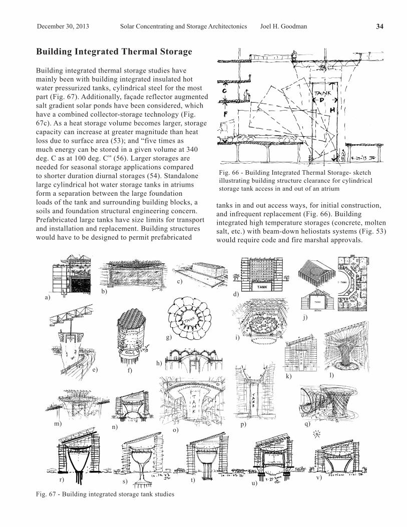
Fig. 67 - Building integrated storage tank studies
Fig. 66 - Building Integrated Thermal Storage- sketch illustrating building structure clearance for cylindrical storage tank access in and out of an atrium
Building Integrated Thermal Storage
Building integrated thermal storage studies have mainly been with building integrated insulated hot water pressurized tanks, cylindrical steel for the most part (Fig. 67). Additionally, façade reflector augmented salt gradient solar ponds have been considered, which have a combined collector-storage technology (Fig. 67c). As a heat storage volume becomes larger, storage capacity can increase at greater magnitude than heat loss due to surface area (53); and “five times as much energy can be stored in a given volume at 340 deg. C as at 100 deg. C” (56). Larger storages are needed for seasonal storage applications compared to shorter duration diurnal storages (54). Standalone large cylindrical hot water storage tanks in atriums form a separation between the large foundation loads of the tank and surrounding building blocks, a soils and foundation structural engineering concern. Prefabricated large tanks have size limits for transport and installation and replacement. Building structures would have to be designed to permit prefabricated
tanks in and out access ways, for initial construction, and infrequent replacement (Fig. 66). Building integrated high temperature storages (concrete, molten salt, etc.) with beam-down heliostats systems (Fig. 53) would require code and fire marshal approvals.
a)b)
j)
d)
c)
f)e)
g) i)
h)
k) l)
m) n) o)p) q)
r) s) t) u)v)
Solar Concentrating and Storage Architectonics Joel H. GoodmanDecember 30, 2013 40
Postscript The old story of the frog staying in the water that is heating up until it is too late seems a more relevant metaphor than ever before. The momentum of designing and constructing buildings that demand energy from fossil fuels endures in: architecture schools, building owner and building committee programs, construction lending institutions, approvers of construction permits, and funders of research. The transition to building integrated active solar-renewable energy systems is underway, but it does not seem fast enough to help much to avoid the predicted climate-change and global warming extremes. And now there is the fracking shale gas rush which will further delay the transition to renewables. Nonetheless, there is some solace in trying for aesthetic adaptation of the built environment. Building integrated active solar is not a passing fad. Convincing research and active solar concentrator demonstration buildings are needed to influence building design decisions. The transition to active solar buildings may have some similarities to the history of building integrated wood fire thermal energy systems (the Franklin stove, wing chairs, etc.) preceding the current fossil fuel period. After concentrating solar radiation for high grade applications (chemical, electrical, and high temperature) – there is also the diminished low temperature energy, therefore to collect only low temperature energy with active systems is like “wasting energy”. Ultimately the economics will be in favor of building integrated active solar when the costs of fossil fuels will be too high. In fact the indirect environmental costs of fossil fuels are already too high. And major remodeling is not cheap for durable building structures that can last for twenty, fifty and over one hundred years. Comparative understanding develops from studies of several concentrating schematic design architectonics, fitting with: solar resource, building types, sizes and spatial forms, structural materials, embedded energy, regional climate factors and applications. The BIETR for cold climates, one of the presented architectonic configurations, is based on the geometrical technology forms of nonimaging concentrating sunlight. The active solar collector and storage architectonic studies in this booklet are being developed as preparation for engineering evaluations and possible merging with all the other structure-form aspects of site specific architectural design. The demonstrated active solar energy collector, storage, and distribution technologies would need to be part of architects understanding before conceptual design begins, and therefore building integrated active solar energy curriculum is advised to be included in the architecture schools. Concentrating sunlight building structures are parts of whole solar cities.
Joel H. Goodman Dec. 20, 2013
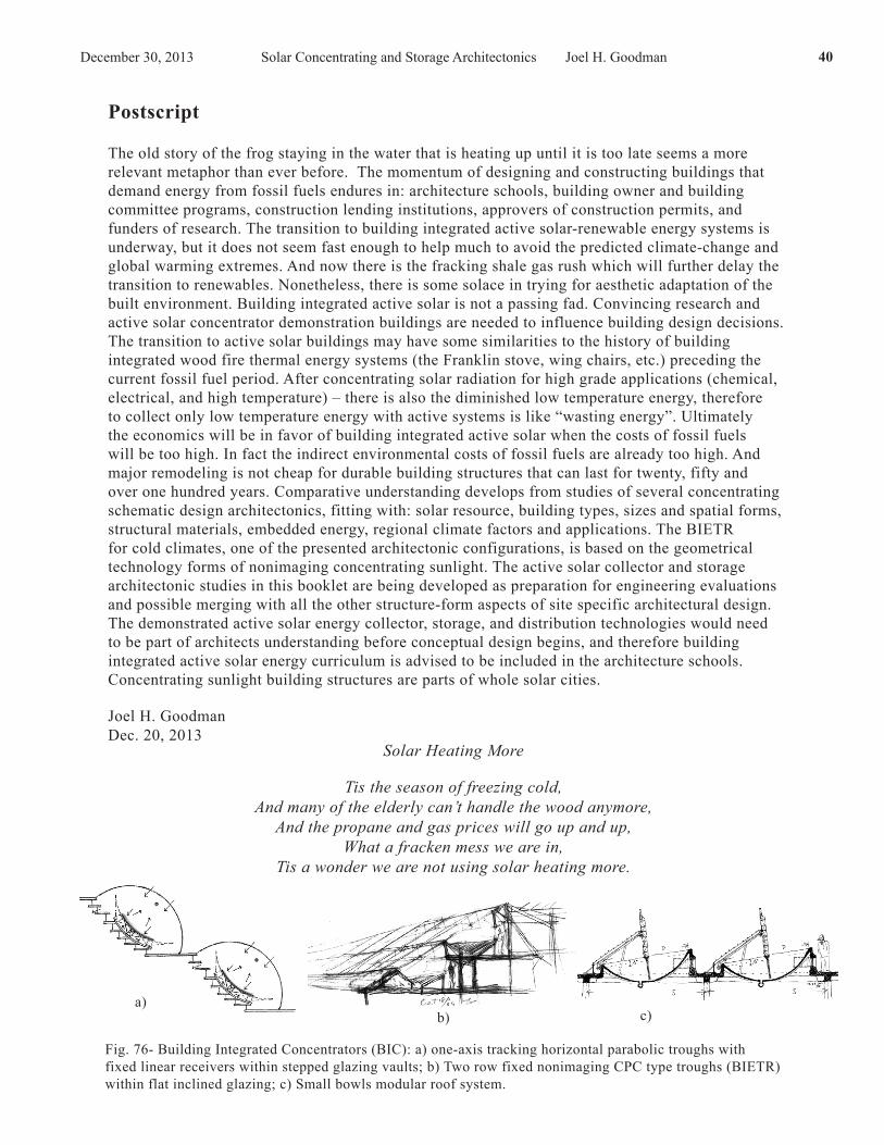
a)b)
Fig. 76- Building Integrated Concentrators (BIC): a) one-axis tracking horizontal parabolic troughs with fixed linear receivers within stepped glazing vaults; b) Two row fixed nonimaging CPC type troughs (BIETR) within flat inclined glazing; c) Small bowls modular roof system.
c)
Solar Heating More
Tis the season of freezing cold,And many of the elderly can’t handle the wood anymore,
And the propane and gas prices will go up and up,What a fracken mess we are in,
Tis a wonder we are not using solar heating more.