Embed Size (px)
Citation preview
Mazumdar Soubhik, et al.; International Journal of Advance Research, Ideas and Innovations in Technology
© 2020, www.IJARIIT.com All Rights Reserved Page | 537
ISSN: 2454-132X
Impact factor: 6.078 (Volume 6, Issue 4)
Available online at: https://www.ijariit.com
Solar-powered semi-autonomous vehicle for agricultural usage
Soubhik Mazumdar [email protected]
Vellore Institute of Technology Chennai, Tamil Nadu
Abhinav Bhattacharya [email protected]
Vellore Institute of Technology Chennai, Tamil Nadu
Kirti Bhagat [email protected]
Vellore Institute of Technology Chennai, Tamil Nadu
Aayush Kumar [email protected]
Vellore Institute of Technology Chennai, Tamil Nadu
Shivam Gupta [email protected]
Vellore Institute of Technology Chennai, Tamil Nadu
Kunal Sahni [email protected]
Vellore Institute of Technology Chennai, Tamil Nadu
Menaka R.
[email protected] Vellore Institute of Technology Chennai, Tamil Nadu
ABSTRACT
The Farm Assistant Robotic Mobile robot, abbreviated as F.A.R.M, is a four-wheel-drive, solar-powered semi-autonomous vehicle designed specifically to suit the needs of a typical Indian farm. Indian agriculture is composed of many crops, rice, and wheat being the most popularly consumed. F.A.R.M has been designed to keep commercial rice and wheat plantations as the primary focal point but can be extended to other farms with minor tweaks. The 20-kg robot can drive with a continuous transnational speed of 8 m/s on moderately rough terrain. The on-board solar panel generates about 150-W of average power when directly under the sun i.e., a 90-degree angle of elevation. The power-control system uses an MPPT based charging system to recharge the batteries and supply loads. The robot has two modes of control; first using a handheld controller, and second using control buttons through a web page. Various features include a pesticide sprayer, live video surveillance, internal system reporting, invasive animal detection using computer vision, and a self-sustained solar energy-based power system. Keywords: Agriculture, Automation, Solar Panel, Battery, MPPT, BMS, openCV, MQTT 1. INTRODUCTION The focus of this research is on modernizing agricultural activities of agriculture in India. According to nationmaster.com, India has 8\% more per capita agricultural growth when compared to the U.S.A with only half (1.8 million sq. km to 4.11 million sq. km) the agricultural land available. USA still manages to have a better production index, 8% more than that of India. 261.1 million workers are involved in this sector in India, the second-largest in the world, compared to only 2.67 million in the USA.When it comes to agricultural value-added per worker1 USA generates 39,125.76 compared to India’s 385.73 as per constant 2000 USD.
Conclusively, it can be said that a lack of automation and technological breakthroughs in India is the reason behind its dire situation in the country as opposed to elsewhere. The F.A.R.M robot aims at introducing automation in the agricultural industry in order to improve production efficiency and yield quality. Using a robust Planetary DC motor drive the bot easily maneuvers across moderately rough terrain typically found in wheat farms. The control is manual by default and can be done using two modes: a hand held remote controller or using an interactive web page with buttons for navigation. The data is transferred to the bot using the MQTT protocol in both cases. Another major problem commonly faced in farms is an animal intrusion. F.A.R.M uses computer vision APIs to detect such threats and use a Gas Shot to scare the animals away without causing any physical harm, much like the technique used in airport runways. Table above lists some of the commonly used pesticides in Indian farms. These are sprayed all over the farm which in many cases leads to wastage and unreasonable and unnecessarily large quantities of these chemicals in the crop. F.A.R.M has a pesticide sprayer mechanism that sprays the chemicals in a controlled manner. The entire power system of the bot is self-contained and self-sufficient. It uses a solar panel fixed on top to recharge its batteries and then drive the mechanisms using the same energy. All the vital signs of the battery pack are monitored and displayed on a local database.[1][2] 1Agriculture value added per worker is a measure of agricultural productivity. Value added in agriculture measures the output of the agricultural sector (ISIC divisions 1-5) less the value of intermediate inputs. Agriculture comprises value added from forestry, hunting, and fishing as well as cultivation of crops and livestock production. Data are in constant 2000 U.S. dollars.
Mazumdar Soubhik, et al.; International Journal of Advance Research, Ideas and Innovations in Technology
© 2020, www.IJARIIT.com All Rights Reserved Page | 538
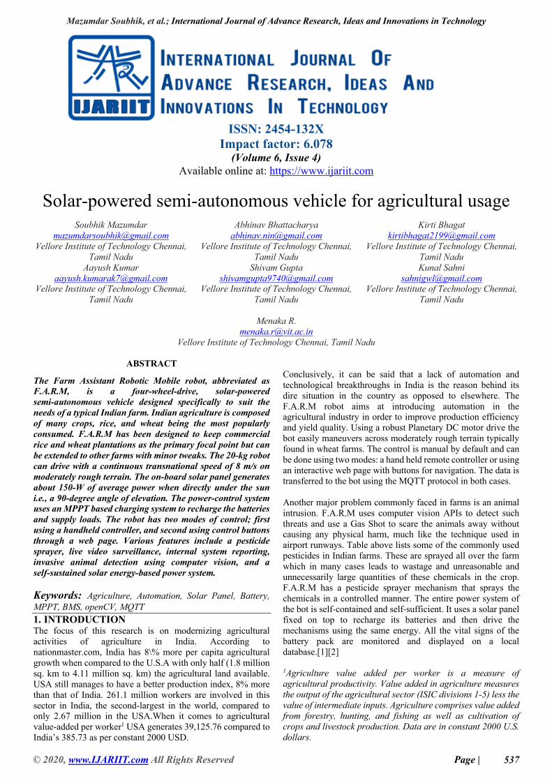
Fig. 1: System Block Diagram
2. RELATED WORK Various research articles and proceedings have inspired the concept for the F.A.R.M robot across international journals. J.H. Lever and A. Streeter made a similar project involving the performance of a solar-powered Robot for polar instrument networks. Their robot is called the ‘cool robot’, which is also a 4-Wheel-Drive like F.A.R.M. The cool bot was deployed at Summit Camp, Greenland during 2005 to validate the parameters it was designed according to, which include power efficiency, solar input, and drive over a rough terrain. It also featured a simple GPS waypoint-following algorithm, which provided reliable autonomous navigation over periods of 5 to 8 hours. The paper suggested reliable a power system specifically for solar powered robots. For creating the most efficient battery charging system we went through Design and Implementation of MPPT Charge Controller by C. R.Sullivan and M. J. Powers.[1][5] 3. MECHANICAL STRUCTURE 3.1 Body Dynamics The mechanical structure primarily consists of aluminum as it provides robustness at the same time keeping the weight and cost at a lower side compared to other materials. As the robotic mobile will be deployed in the fields, there will be unevenness and hence suspension will be required. The F.A.R.M. incorporates a pair of front wheels and back wheels, since the vehicle is four wheel drive all the wheels are powered by a motor to pull the it forward and suspensions will also be present to decrease the shock exerted due to the uneven terrain. As the vehicle utilizes the solar rays to generate power, there are two solar panels – the power ratings are discussed in the subsequent sections. As the Tropic of Cancer passes through the middle of the country, the sun’s position is almost overhead at the noontime and hence maximum power is captured during the noon and the afternoon time. CAD design dimensions are 700mm x 850mm x 500mm.
Fig. 2: Elementary CAD Model of Vehicle
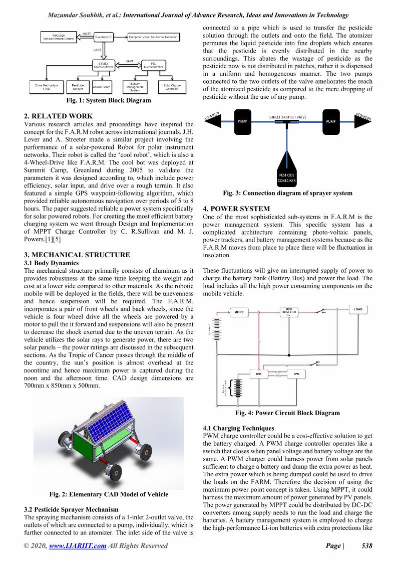
3.2 Pesticide Sprayer Mechanism The spraying mechanism consists of a 1-inlet 2-outlet valve, the outlets of which are connected to a pump, individually, which is further connected to an atomizer. The inlet side of the valve is
connected to a pipe which is used to transfer the pesticide solution through the outlets and onto the field. The atomizer permutes the liquid pesticide into fine droplets which ensures that the pesticide is evenly distributed in the nearby surroundings. This abates the wastage of pesticide as the pesticide now is not distributed in patches, rather it is dispensed in a uniform and homogeneous manner. The two pumps connected to the two outlets of the valve ameliorates the reach of the atomized pesticide as compared to the mere dropping of pesticide without the use of any pump.
Fig. 3: Connection diagram of sprayer system
4. POWER SYSTEM One of the most sophisticated sub-systems in F.A.R.M is the power management system. This specific system has a complicated architecture containing photo-voltaic panels, power trackers, and battery management systems because as the F.A.R.M moves from place to place there will be fluctuation in insolation. These fluctuations will give an interrupted supply of power to charge the battery bank (Battery Bus) and power the load. The load includes all the high power consuming components on the mobile vehicle.
Fig. 4: Power Circuit Block Diagram
4.1 Charging Techniques PWM charge controller could be a cost-effective solution to get the battery charged. A PWM charge controller operates like a switch that closes when panel voltage and battery voltage are the same. A PWM charger could harness power from solar panels sufficient to charge a battery and dump the extra power as heat. The extra power which is being dumped could be used to drive the loads on the FARM. Therefore the decision of using the maximum power point concept is taken. Using MPPT, it could harness the maximum amount of power generated by PV panels. The power generated by MPPT could be distributed by DC-DC converters among supply needs to run the load and charge the batteries. A battery management system is employed to charge the high-performance Li-ion batteries with extra protections like
Mazumdar Soubhik, et al.; International Journal of Advance Research, Ideas and Innovations in Technology
© 2020, www.IJARIIT.com All Rights Reserved Page | 539
overcharge, over-discharge, load connect function, etc, and hence increase the life of the battery. The control unit of the FARM will exclusively be powered by the battery bank. DC-DC Buck converter used to match the load specific voltage requirement from the energy produced by the solar panel. Adding to this, a plausible case, when insolation goes way lower than the power needs of FARM to run the load, the power requirement from there on will be provided by a battery bank, hence making the system robust.
Fig. 5: Using a pulse width modulation charger to test the
efficiency of the solar panel
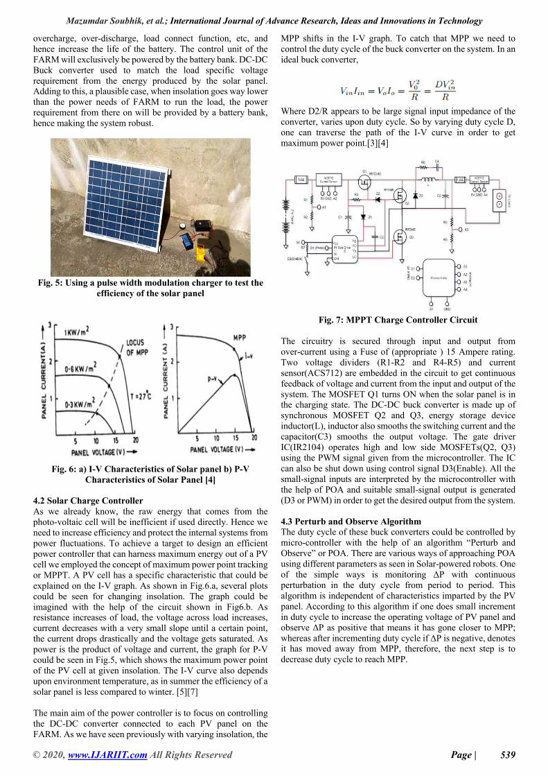
Fig. 6: a) I-V Characteristics of Solar panel b) P-V
Characteristics of Solar Panel [4] 4.2 Solar Charge Controller As we already know, the raw energy that comes from the photo-voltaic cell will be inefficient if used directly. Hence we need to increase efficiency and protect the internal systems from power fluctuations. To achieve a target to design an efficient power controller that can harness maximum energy out of a PV cell we employed the concept of maximum power point tracking or MPPT. A PV cell has a specific characteristic that could be explained on the I-V graph. As shown in Fig.6.a, several plots could be seen for changing insolation. The graph could be imagined with the help of the circuit shown in Fig6.b. As resistance increases of load, the voltage across load increases, current decreases with a very small slope until a certain point, the current drops drastically and the voltage gets saturated. As power is the product of voltage and current, the graph for P-V could be seen in Fig.5, which shows the maximum power point of the PV cell at given insolation. The I-V curve also depends upon environment temperature, as in summer the efficiency of a solar panel is less compared to winter. [5][7] The main aim of the power controller is to focus on controlling the DC-DC converter connected to each PV panel on the FARM. As we have seen previously with varying insolation, the
MPP shifts in the I-V graph. To catch that MPP we need to control the duty cycle of the buck converter on the system. In an ideal buck converter,
Where D2/R appears to be large signal input impedance of the converter, varies upon duty cycle. So by varying duty cycle D, one can traverse the path of the I-V curve in order to get maximum power point.[3][4]
Fig. 7: MPPT Charge Controller Circuit
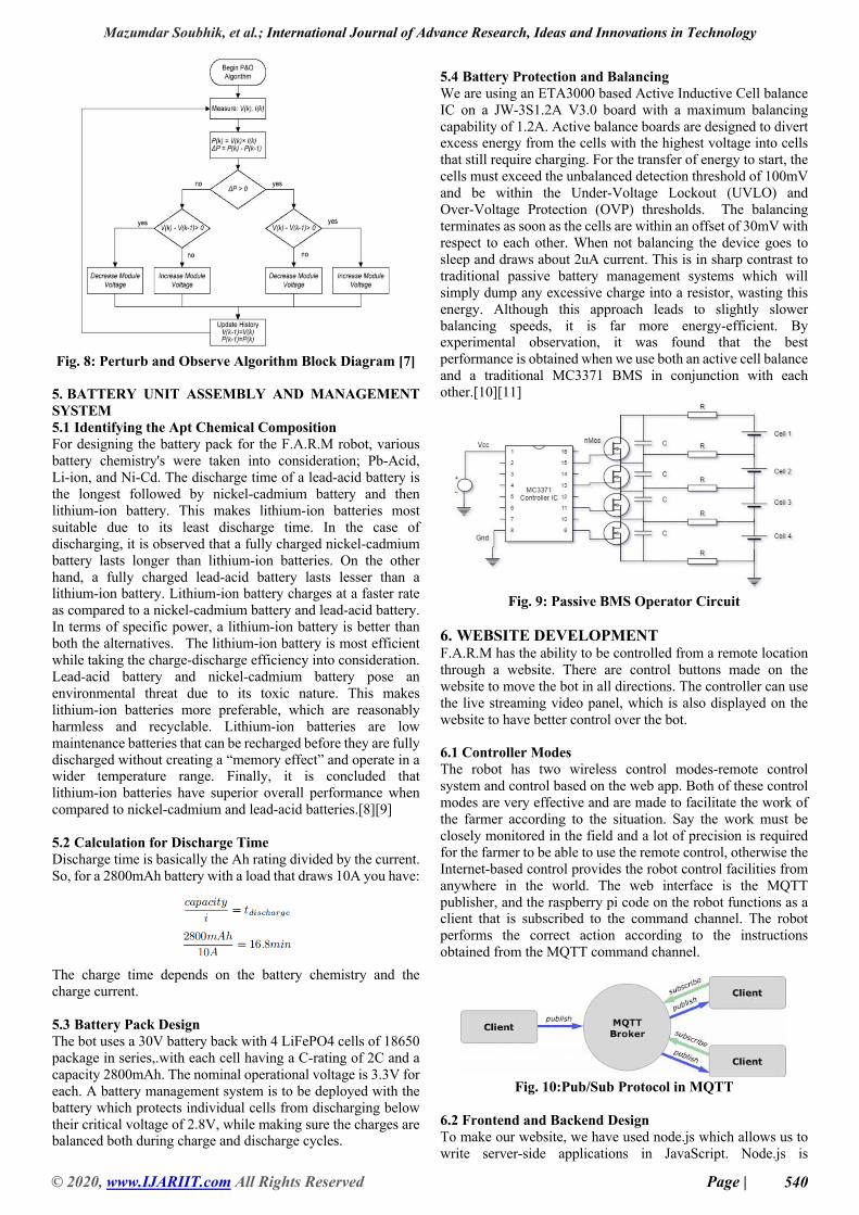
The circuitry is secured through input and output from over-current using a Fuse of (appropriate ) 15 Ampere rating. Two voltage dividers (R1-R2 and R4-R5) and current sensor(ACS712) are embedded in the circuit to get continuous feedback of voltage and current from the input and output of the system. The MOSFET Q1 turns ON when the solar panel is in the charging state. The DC-DC buck converter is made up of synchronous MOSFET Q2 and Q3, energy storage device inductor(L), inductor also smooths the switching current and the capacitor(C3) smooths the output voltage. The gate driver IC(IR2104) operates high and low side MOSFETs(Q2, Q3) using the PWM signal given from the microcontroller. The IC can also be shut down using control signal D3(Enable). All the small-signal inputs are interpreted by the microcontroller with the help of POA and suitable small-signal output is generated (D3 or PWM) in order to get the desired output from the system. 4.3 Perturb and Observe Algorithm The duty cycle of these buck converters could be controlled by micro-controller with the help of an algorithm “Perturb and Observe” or POA. There are various ways of approaching POA using different parameters as seen in Solar-powered robots. One of the simple ways is monitoring ΔP with continuous perturbation in the duty cycle from period to period. This algorithm is independent of characteristics imparted by the PV panel. According to this algorithm if one does small increment in duty cycle to increase the operating voltage of PV panel and observe ΔP as positive that means it has gone closer to MPP; whereas after incrementing duty cycle if ΔP is negative, denotes it has moved away from MPP, therefore, the next step is to decrease duty cycle to reach MPP.
Mazumdar Soubhik, et al.; International Journal of Advance Research, Ideas and Innovations in Technology
© 2020, www.IJARIIT.com All Rights Reserved Page | 540
Fig. 8: Perturb and Observe Algorithm Block Diagram [7]
5. BATTERY UNIT ASSEMBLY AND MANAGEMENT SYSTEM 5.1 Identifying the Apt Chemical Composition For designing the battery pack for the F.A.R.M robot, various battery chemistry's were taken into consideration; Pb-Acid, Li-ion, and Ni-Cd. The discharge time of a lead-acid battery is the longest followed by nickel-cadmium battery and then lithium-ion battery. This makes lithium-ion batteries most suitable due to its least discharge time. In the case of discharging, it is observed that a fully charged nickel-cadmium battery lasts longer than lithium-ion batteries. On the other hand, a fully charged lead-acid battery lasts lesser than a lithium-ion battery. Lithium-ion battery charges at a faster rate as compared to a nickel-cadmium battery and lead-acid battery. In terms of specific power, a lithium-ion battery is better than both the alternatives. The lithium-ion battery is most efficient while taking the charge-discharge efficiency into consideration. Lead-acid battery and nickel-cadmium battery pose an environmental threat due to its toxic nature. This makes lithium-ion batteries more preferable, which are reasonably harmless and recyclable. Lithium-ion batteries are low maintenance batteries that can be recharged before they are fully discharged without creating a “memory effect” and operate in a wider temperature range. Finally, it is concluded that lithium-ion batteries have superior overall performance when compared to nickel-cadmium and lead-acid batteries.[8][9] 5.2 Calculation for Discharge Time Discharge time is basically the Ah rating divided by the current. So, for a 2800mAh battery with a load that draws 10A you have:
The charge time depends on the battery chemistry and the charge current. 5.3 Battery Pack Design The bot uses a 30V battery back with 4 LiFePO4 cells of 18650 package in series,.with each cell having a C-rating of 2C and a capacity 2800mAh. The nominal operational voltage is 3.3V for each. A battery management system is to be deployed with the battery which protects individual cells from discharging below their critical voltage of 2.8V, while making sure the charges are balanced both during charge and discharge cycles.
5.4 Battery Protection and Balancing We are using an ETA3000 based Active Inductive Cell balance IC on a JW-3S1.2A V3.0 board with a maximum balancing capability of 1.2A. Active balance boards are designed to divert excess energy from the cells with the highest voltage into cells that still require charging. For the transfer of energy to start, the cells must exceed the unbalanced detection threshold of 100mV and be within the Under-Voltage Lockout (UVLO) and Over-Voltage Protection (OVP) thresholds. The balancing terminates as soon as the cells are within an offset of 30mV with respect to each other. When not balancing the device goes to sleep and draws about 2uA current. This is in sharp contrast to traditional passive battery management systems which will simply dump any excessive charge into a resistor, wasting this energy. Although this approach leads to slightly slower balancing speeds, it is far more energy-efficient. By experimental observation, it was found that the best performance is obtained when we use both an active cell balance and a traditional MC3371 BMS in conjunction with each other.[10][11]
Fig. 9: Passive BMS Operator Circuit
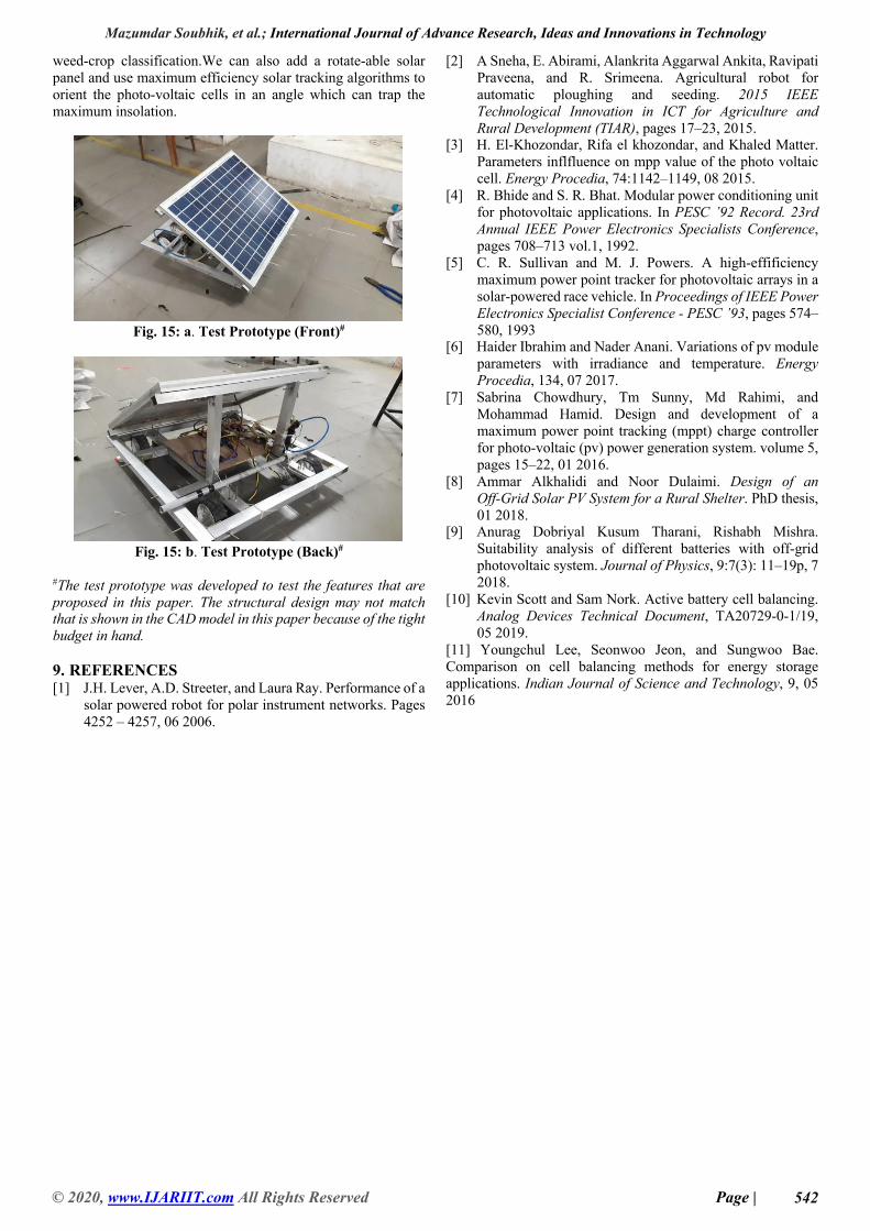
6. WEBSITE DEVELOPMENT F.A.R.M has the ability to be controlled from a remote location through a website. There are control buttons made on the website to move the bot in all directions. The controller can use the live streaming video panel, which is also displayed on the website to have better control over the bot. 6.1 Controller Modes The robot has two wireless control modes-remote control system and control based on the web app. Both of these control modes are very effective and are made to facilitate the work of the farmer according to the situation. Say the work must be closely monitored in the field and a lot of precision is required for the farmer to be able to use the remote control, otherwise the Internet-based control provides the robot control facilities from anywhere in the world. The web interface is the MQTT publisher, and the raspberry pi code on the robot functions as a client that is subscribed to the command channel. The robot performs the correct action according to the instructions obtained from the MQTT command channel.
Fig. 10:Pub/Sub Protocol in MQTT
6.2 Frontend and Backend Design To make our website, we have used node.js which allows us to write server-side applications in JavaScript. Node.js is
Mazumdar Soubhik, et al.; International Journal of Advance Research, Ideas and Innovations in Technology
© 2020, www.IJARIIT.com All Rights Reserved Page | 541
lightweight, efficient, and has a unique asynchronous nature. This leads to input/output processing that permits other processing to continue before the transmission has finished. Node.js is a good choice for our real-time application where we have to process a high volume of short messages and require low latency. We have used JavaScript for our front end along with HTML and CSS.
Fig. 11: Architecture of the Web Interface
Fig. 12: Website Frontend Design
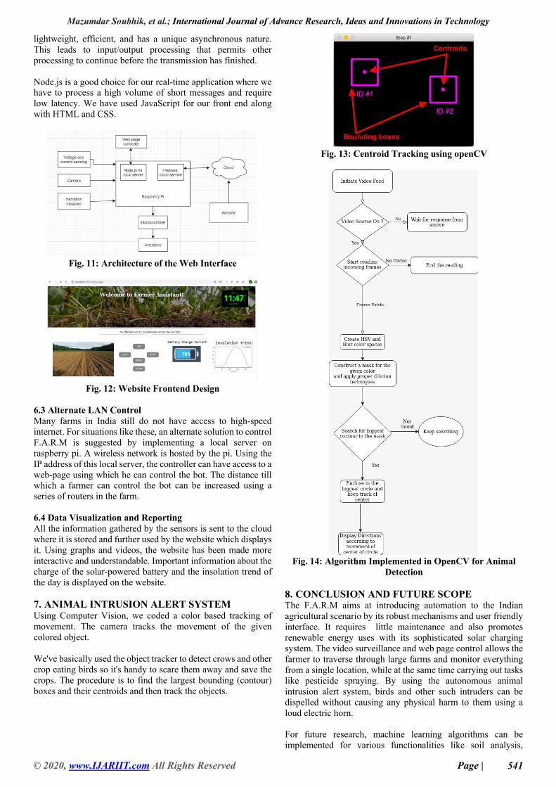
6.3 Alternate LAN Control Many farms in India still do not have access to high-speed internet. For situations like these, an alternate solution to control F.A.R.M is suggested by implementing a local server on raspberry pi. A wireless network is hosted by the pi. Using the IP address of this local server, the controller can have access to a web-page using which he can control the bot. The distance till which a farmer can control the bot can be increased using a series of routers in the farm. 6.4 Data Visualization and Reporting All the information gathered by the sensors is sent to the cloud where it is stored and further used by the website which displays it. Using graphs and videos, the website has been made more interactive and understandable. Important information about the charge of the solar-powered battery and the insolation trend of the day is displayed on the website. 7. ANIMAL INTRUSION ALERT SYSTEM Using Computer Vision, we coded a color based tracking of movement. The camera tracks the movement of the given colored object. We've basically used the object tracker to detect crows and other crop eating birds so it's handy to scare them away and save the crops. The procedure is to find the largest bounding (contour) boxes and their centroids and then track the objects.
Fig. 13: Centroid Tracking using openCV
Fig. 14: Algorithm Implemented in OpenCV for Animal
Detection 8. CONCLUSION AND FUTURE SCOPE The F.A.R.M aims at introducing automation to the Indian agricultural scenario by its robust mechanisms and user friendly interface. It requires little maintenance and also promotes renewable energy uses with its sophisticated solar charging system. The video surveillance and web page control allows the farmer to traverse through large farms and monitor everything from a single location, while at the same time carrying out tasks like pesticide spraying. By using the autonomous animal intrusion alert system, birds and other such intruders can be dispelled without causing any physical harm to them using a loud electric horn. For future research, machine learning algorithms can be implemented for various functionalities like soil analysis,
Mazumdar Soubhik, et al.; International Journal of Advance Research, Ideas and Innovations in Technology
© 2020, www.IJARIIT.com All Rights Reserved Page | 542
weed-crop classification.We can also add a rotate-able solar panel and use maximum efficiency solar tracking algorithms to orient the photo-voltaic cells in an angle which can trap the maximum insolation.
Fig. 15: a. Test Prototype (Front)#
Fig. 15: b. Test Prototype (Back)#
#The test prototype was developed to test the features that are proposed in this paper. The structural design may not match that is shown in the CAD model in this paper because of the tight budget in hand. 9. REFERENCES [1] J.H. Lever, A.D. Streeter, and Laura Ray. Performance of a
solar powered robot for polar instrument networks. Pages 4252 – 4257, 06 2006.
[2] A Sneha, E. Abirami, Alankrita Aggarwal Ankita, Ravipati Praveena, and R. Srimeena. Agricultural robot for automatic ploughing and seeding. 2015 IEEE Technological Innovation in ICT for Agriculture and Rural Development (TIAR), pages 17–23, 2015.
[3] H. El-Khozondar, Rifa el khozondar, and Khaled Matter. Parameters inflfluence on mpp value of the photo voltaic cell. Energy Procedia, 74:1142–1149, 08 2015.
[4] R. Bhide and S. R. Bhat. Modular power conditioning unit for photovoltaic applications. In PESC ’92 Record. 23rd Annual IEEE Power Electronics Specialists Conference, pages 708–713 vol.1, 1992.
[5] C. R. Sullivan and M. J. Powers. A high-effificiency maximum power point tracker for photovoltaic arrays in a solar-powered race vehicle. In Proceedings of IEEE Power Electronics Specialist Conference - PESC ’93, pages 574–580, 1993
[6] Haider Ibrahim and Nader Anani. Variations of pv module parameters with irradiance and temperature. Energy Procedia, 134, 07 2017.
[7] Sabrina Chowdhury, Tm Sunny, Md Rahimi, and Mohammad Hamid. Design and development of a maximum power point tracking (mppt) charge controller for photo-voltaic (pv) power generation system. volume 5, pages 15–22, 01 2016.
[8] Ammar Alkhalidi and Noor Dulaimi. Design of an Off-Grid Solar PV System for a Rural Shelter. PhD thesis, 01 2018.
[9] Anurag Dobriyal Kusum Tharani, Rishabh Mishra. Suitability analysis of different batteries with off-grid photovoltaic system. Journal of Physics, 9:7(3): 11–19p, 7 2018.
[10] Kevin Scott and Sam Nork. Active battery cell balancing. Analog Devices Technical Document, TA20729-0-1/19, 05 2019.
[11] Youngchul Lee, Seonwoo Jeon, and Sungwoo Bae. Comparison on cell balancing methods for energy storage applications. Indian Journal of Science and Technology, 9, 05 2016


![Autonomous Driving Validation using Game Engine …...autonomous vehicle validation [ õ] and hence use it in HiL, SiL, ViL, PiL, MiL and DiL applications. Game engines enable usage](https://img.pdfslide.net/doc/110x75/5ec244f976d3456b66474d89/autonomous-driving-validation-using-game-engine-autonomous-vehicle-validation.jpg)