Embed Size (px)
Citation preview
Chapter 7
Chapter 7
SOLAR RADIATION
Solar radiation has important effects on both the heat gain and heat loss of a building.
The designer should distinguish between the maximum solar load on a surfacewhich is important for load calculations against an average value that the surface experi-ences.
Key issues to be learned:
a. Thermal Radiationb. Earth-Sun geometryc. Solar Time, Local Standard Timed. Solar Anglese. Solar Irradiation, Mean Solar Constant
• ASHRAE Clear Sky Modelf. Heat Gain Through Fenestrations
• Solar Heat Gain Coefficients• Simplified Solar Heat Gain Calculations• Shading Coefficient
g. Energy Calculations
QUESTION
Is there any usable solar energy available in Houghton during the month ofMarch? If yes, where is it?
ANSWER
Yes. Behind the clouds. Very obvious in a clear day!
Page 1
Chapter 7
7-1 Thermal Radiation
The perfect radiant emitter is also given a name blackbody. For a given temperature T inR (K), a black emitter exhibits a maximum monochromatic emissive power at wavelengthlmax, given by
microns (7-2)
This equation is known as Wien’s displacement law.
For nonblack surfaces, the emittance e, leads to actual energy emitted from a sur-face
(7-3)
where
Table 7-1 Solar Absorptances (See book for more)
Surface Absorptance
BrickPaint, sandstonePaint, white acrylicSheet metal, galvanized, newSheet metal, galvanized, weatheredConcreteAsphaltGrasslandSnow, freshSnow, old
0.630.500.260.650.80
0.60-0.830.90-0.950.80-0.840.10-0.250.30-0.55
λmax5215.6 2897.6( )
T-----------------------------------------=
E εEb=
Eb σT4=
Page 2
Chapter 7
7-2 The Earth’s Motion About the Sun
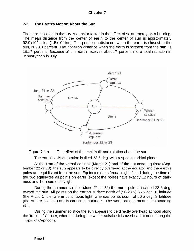
The sun’s position in the sky is a major factor in the effect of solar energy on a building.The mean distance from the center of earth to the center of sun is approximately92.9x106 miles (1.5x10⁸ km). The perihelion distance, when the earth is closest to thesun, is 98.3 percent. The aphelion distance when the earth is farthest from the sun, is101.7 percent. Because of this earth receives about 7 percent more total radiation inJanuary than in July.
Figure 7-1.a The effect of the earth’s tilt and rotation about the sun.
The earth’s axis of rotation is tilted 23.5 deg. with respect to orbital plane.
At the time of the vernal equinox (March 21) and of the autumnal equinox (Sep-tember 22 or 23), the sun appears to be directly overhead at the equator and the earth’spoles are equidistant from the sun. Equinox means “equal nights,” and during the time ofthe two equinoxes all points on earth (except the poles) have exactly 12 hours of dark-ness and 12 hours of daylight.
During the summer solstice (June 21 or 22) the north pole is inclined 23.5 deg.toward the sun. All points on the earth’s surface north of (90-23.5) 66.5 deg. N latitude(the Arctic Circle) are in continuous light, whereas points south of 66.5 deg. S latitude(the Antarctic Circle) are in continuos darkness. The word solstice means sun standingstill.
During the summer solstice the sun appears to be directly overhead at noon alongthe Tropic of Cancer, whereas during the winter solstice it is overhead at noon along theTropic of Capricorn.
Page 3
Chapter 7
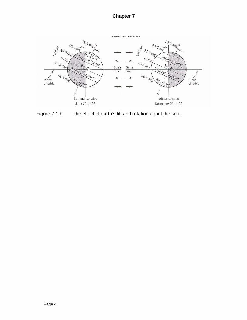
Figure 7-1.b The effect of earth’s tilt and rotation about the sun.
Page 4
Chapter 7
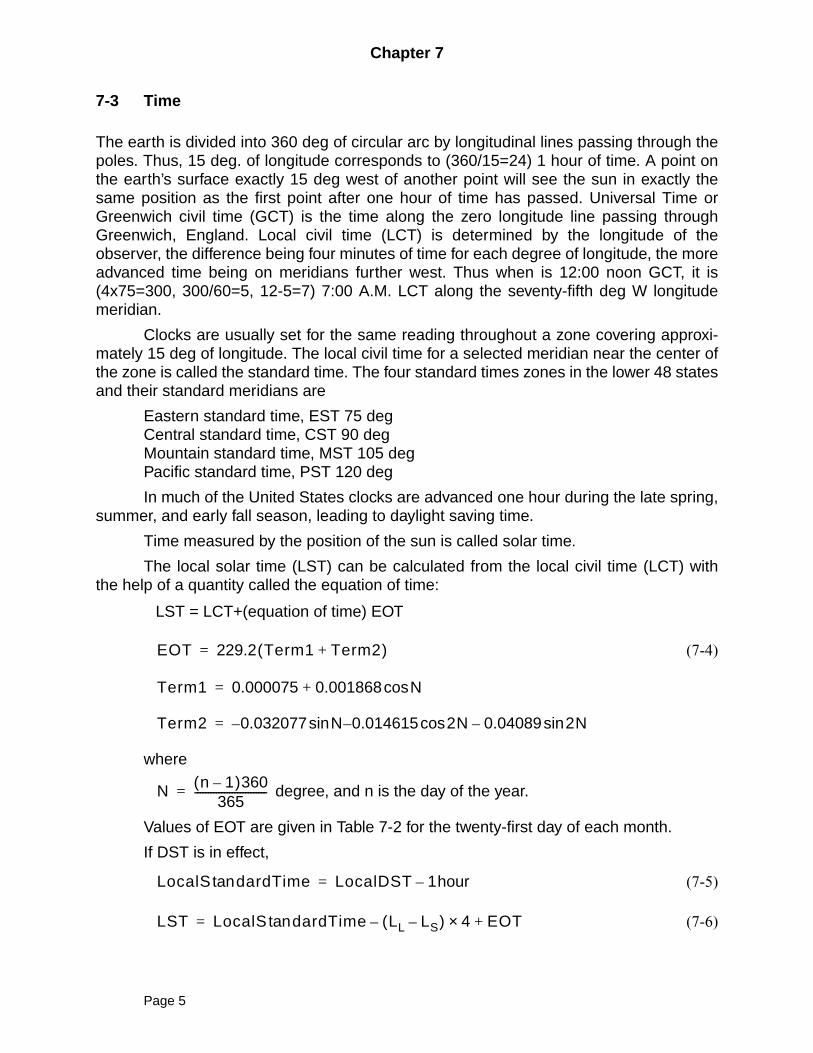
7-3 Time
The earth is divided into 360 deg of circular arc by longitudinal lines passing through thepoles. Thus, 15 deg. of longitude corresponds to (360/15=24) 1 hour of time. A point onthe earth’s surface exactly 15 deg west of another point will see the sun in exactly thesame position as the first point after one hour of time has passed. Universal Time orGreenwich civil time (GCT) is the time along the zero longitude line passing throughGreenwich, England. Local civil time (LCT) is determined by the longitude of theobserver, the difference being four minutes of time for each degree of longitude, the moreadvanced time being on meridians further west. Thus when is 12:00 noon GCT, it is(4x75=300, 300/60=5, 12-5=7) 7:00 A.M. LCT along the seventy-fifth deg W longitudemeridian.
Clocks are usually set for the same reading throughout a zone covering approxi-mately 15 deg of longitude. The local civil time for a selected meridian near the center ofthe zone is called the standard time. The four standard times zones in the lower 48 statesand their standard meridians are
Eastern standard time, EST 75 degCentral standard time, CST 90 degMountain standard time, MST 105 degPacific standard time, PST 120 deg
In much of the United States clocks are advanced one hour during the late spring,summer, and early fall season, leading to daylight saving time.
Time measured by the position of the sun is called solar time.
The local solar time (LST) can be calculated from the local civil time (LCT) withthe help of a quantity called the equation of time:
LST = LCT+(equation of time) EOT
(7-4)
where
degree, and n is the day of the year.
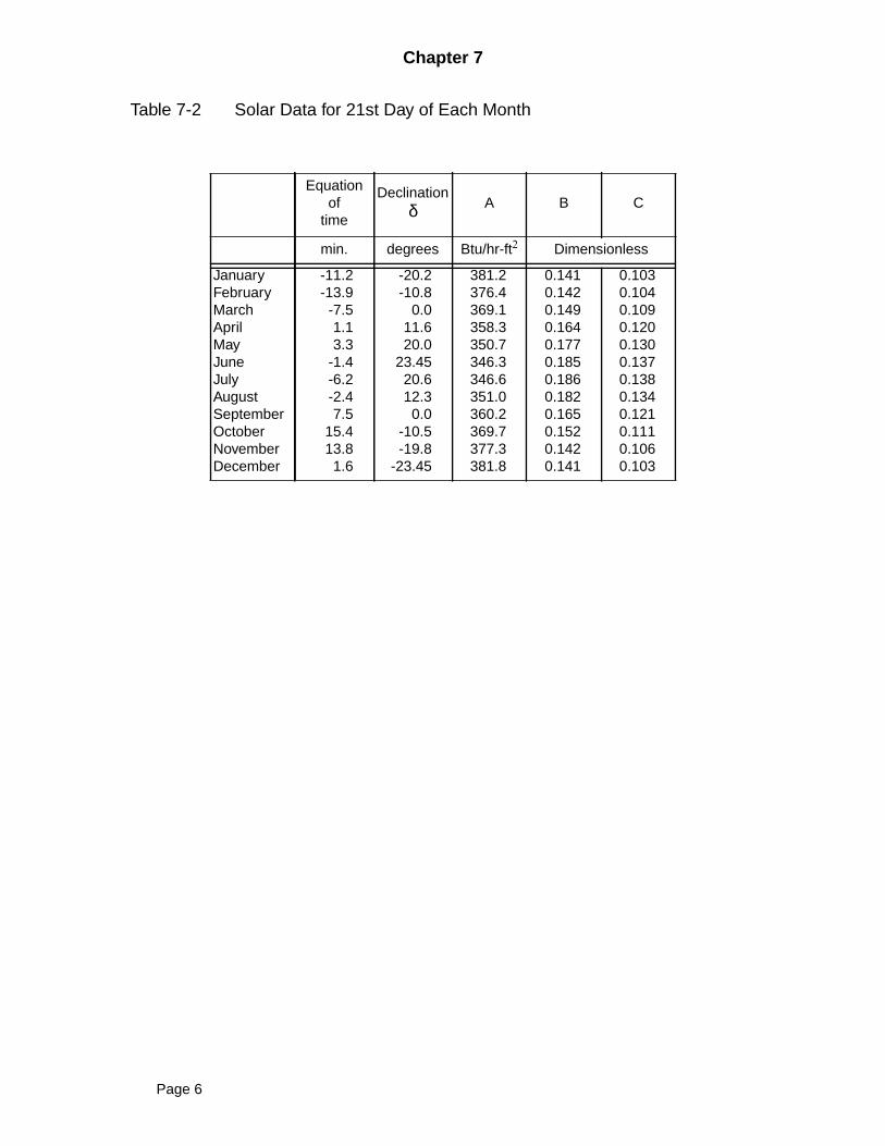
Values of EOT are given in Table 7-2 for the twenty-first day of each month.
If DST is in effect,
(7-5)
(7-6)
EOT 229.2 Term1 Term2+( )=
Term1 0.000075 0.001868 Ncos+=
Term2 0.032077 N 0.014615 2N 0.04089 2Nsin–cos–sin–=
N n 1–( )360365
---------------------------=
LocalS dardTimetan LocalDST 1hour–=
LST LocalS dardTime LL LS–( ) 4 EOT+×–tan=
Page 5
Chapter 7
Table 7-2 Solar Data for 21st Day of Each Month
Equationof
time
Declinationδ A B C
min. degrees Btu/hr-ft2 Dimensionless
JanuaryFebruaryMarchAprilMayJuneJulyAugustSeptemberOctoberNovemberDecember
-11.2-13.9-7.51.13.3
-1.4-6.2-2.47.5
15.413.81.6
-20.2-10.8
0.011.620.0
23.4520.612.30.0
-10.5-19.8
-23.45
381.2376.4369.1358.3350.7346.3346.6351.0360.2369.7377.3381.8
0.1410.1420.1490.1640.1770.1850.1860.1820.1650.1520.1420.141
0.1030.1040.1090.1200.1300.1370.1380.1340.1210.1110.1060.103
Page 6
Chapter 7
Example 7-1
McQuiston, Parker, Spitler; Chapter VIIExample 7-1Calculate the solar time for Houghton at 12:00 P.M. on July 21
SOLUTION
Define dimensional unit
HM = 60 min/hrYear = 365 dayDeg = 360 degW = 4 min/degNN = 1 dayH = 1 hrDC = 23.45 degDN = 284 dayLSolN = 12 hrHL = 15 deg/hrCalculate solar time for HoughtonDS = 1 Daylight saving is ONEST = 75 eastern standard timeLong = 88.39 WestLat = 47.90 NorthMonth February, Day 21Jan=31, Feb=28, Mar=31, Apr=30, May=31, Jun=30, Jul=31, Aug=31, Sep=30, Oct=31, Nov=30,
Dec=31day = 31+ 28 + 31 + 30 + 31 + 30 + 21 July 21N = (day - NN) * Deg / YearEOT = 229.2*(0.000075+0.001868*cos(N)-0.032077*sin(N)-0.014615*cos(2*N)-0.04089*sin(2*N))
minutesGIVENLDST_h = 12 local daylight savings time, hoursLDST_m = 0 local daylight savings time, minutesEnd of given timeLSdT = LDST_h - DS eastern standard time at EST corrected by daylight saving, hoursCalculate local standard timeDiff = (Long - EST) * WLSolT_m = - Diff + EOT in minutesRatio = LSolT_m / HM/HHN = H * Trunc(Ratio)LSolT_h = LDST_h + HNMinutes = LSolT_m - HM * HNLSolT = LSolT_h + minutes / HMH_deg = (LSolT - LSolN) * HLDescribe Collector GeometryPSI = 0.0alpha = 0.0gamma = abs(phi - PSI)delta_1 = DC * Sin(Deg * (DN + day)/Year)Term_1 = 0.3963723 - 22.9132745*Cos(N) + 4.0254304 * Sin(N)Term_2 = -0.3872050 * Cos (2*N) + 0.05196728 * Sin (2*N) - 0.1545267 * Cos(3*N) + 0.08479777 *
Sin(3*N)
Page 7
Chapter 7
delta_2 = Term_1 + Term_2SB = Cos(Lat) * Cos(H_deg) * Cos(delta_2) + Sin(Lat) * Sin (delta_2)beta = arcsin(SB)theta_Z = arccos(SB)CP = (Sin(delta_2) * Cos(Lat) - Cos(delta_2) * Sin(Lat) * Cos(H_deg))/Cos(beta)phi = arccos(CP)CT = Cos(beta) * Cos(gamma) * Sin(alpha) + Sin(beta) * Cos(alpha)theta = arccos(CT)sum = beta + theta_Z
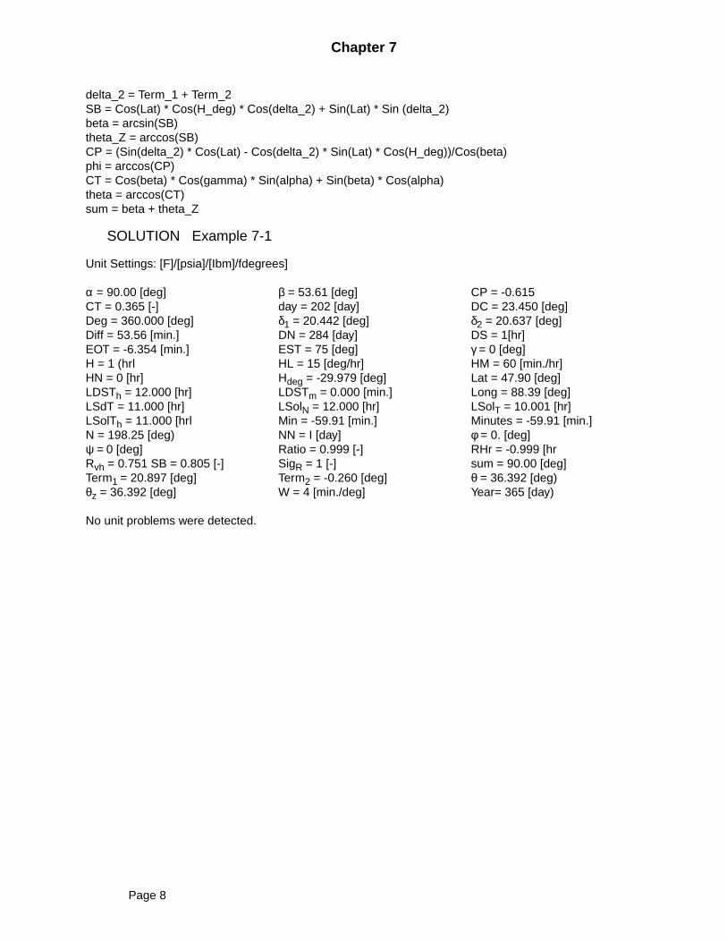
SOLUTION Example 7-1
Unit Settings: [F]/[psia]/[Ibm]/fdegrees]
α = 90.00 [deg] β = 53.61 [deg] CP = -0.615CT = 0.365 [-] day = 202 [day] DC = 23.450 [deg]Deg = 360.000 [deg] δ1 = 20.442 [deg] δ2 = 20.637 [deg]Diff = 53.56 [min.] DN = 284 [day] DS = 1[hr]EOT = -6.354 [min.] EST = 75 [deg] γ = 0 [deg]H = 1 (hrl HL = 15 [deg/hr] HM = 60 [min./hr]HN = 0 [hr] Hdeg = -29.979 [deg] Lat = 47.90 [deg]LDSTh = 12.000 [hr] LDSTm = 0.000 [min.] Long = 88.39 [deg]LSdT = 11.000 [hr] LSolN = 12.000 [hr] LSolT = 10.001 [hr]LSolTh = 11.000 [hrl Min = -59.91 [min.] Minutes = -59.91 [min.]N = 198.25 [deg) NN = I [day] φ = 0. [deg]ψ = 0 [deg] Ratio = 0.999 [-] RHr = -0.999 [hrRvh = 0.751 SB = 0.805 [-] SigR = 1 [-] sum = 90.00 [deg]Term1 = 20.897 [deg] Term2 = -0.260 [deg] θ = 36.392 [deg)θz = 36.392 [deg] W = 4 [min./deg] Year= 365 [day)
No unit problems were detected.
Page 8
Chapter 7
7-4 Solar Angles
Nomenclature:
l latitudeh hour anglen day numberδ declinationN parameterβ solar altitude angleθZ sun’s zenith angleφ solar azimuth angleγ surface solar azimuth angleθ angle of incidenceα tilt angle
The direction of sun rays can be described if the following three quantities are known
1. Location on the earth’s surface (latitude, l)
2. Time of day
3. Day of the year (n)
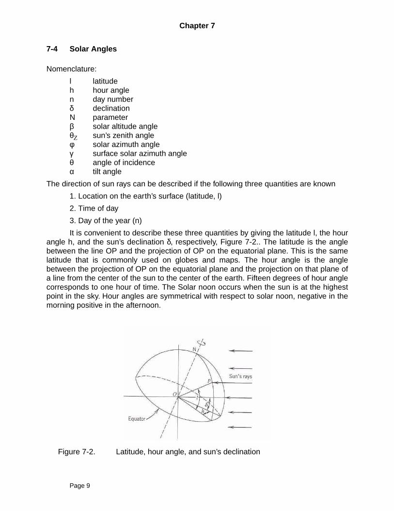
It is convenient to describe these three quantities by giving the latitude l, the hourangle h, and the sun’s declination δ, respectively, Figure 7-2.. The latitude is the anglebetween the line OP and the projection of OP on the equatorial plane. This is the samelatitude that is commonly used on globes and maps. The hour angle is the anglebetween the projection of OP on the equatorial plane and the projection on that plane ofa line from the center of the sun to the center of the earth. Fifteen degrees of hour anglecorresponds to one hour of time. The Solar noon occurs when the sun is at the highestpoint in the sky. Hour angles are symmetrical with respect to solar noon, negative in themorning positive in the afternoon.
Figure 7-2. Latitude, hour angle, and sun’s declination
Page 9
Chapter 7
The sun’s declination is the angle between a line connecting the center of the sunand earth and the projection of this line on equatorial plane. It varies between +23.45and -23.45 degrees.
(7-7)
NOTE: Compare (7-7) with that in the text, page 188.
δ =0.3963723 - 22.9132745 CosN + 4.0254304 SinN - 0.3872050 Cos2N
+ 0.05196728 Sin2N - 0.1545267 Cos3N + 0.08479777 Sin3N
Table 7-2 shows typical values of the sun’s declination for the twenty-first day ofeach month.
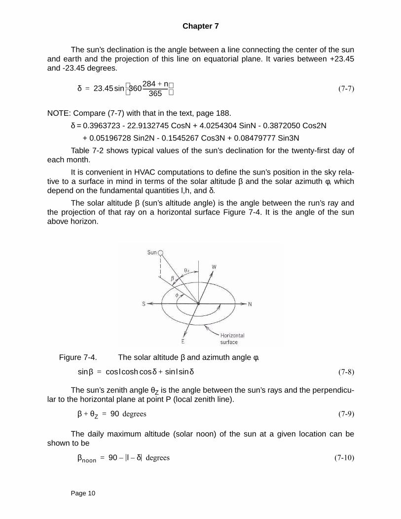
It is convenient in HVAC computations to define the sun’s position in the sky rela-tive to a surface in mind in terms of the solar altitude β and the solar azimuth φ, whichdepend on the fundamental quantities l,h, and δ.
The solar altitude β (sun’s altitude angle) is the angle between the run’s ray andthe projection of that ray on a horizontal surface Figure 7-4. It is the angle of the sunabove horizon.
Figure 7-4. The solar altitude β and azimuth angle φ.
(7-8)
The sun’s zenith angle θZ is the angle between the sun’s rays and the perpendicu-lar to the horizontal plane at point P (local zenith line).
degrees (7-9)
The daily maximum altitude (solar noon) of the sun at a given location can beshown to be
degrees (7-10)
δ 23.45 360284 n+
365-------------------
sin=
βsin l δ l δsinsin+coscoshcos=
β θZ+ 90=
βnoon 90 l δ––=
Page 10
Chapter 7
The solar azimuth angle φ is the angle in the horizontal plane measured, in theclockwise direction, between north and the projection of the sun’s rays on that plane.
(7-11)
Note that, when calculating φ by taking the inverse of Cosφ, it is necessary tocheck which quadrant φ is in.
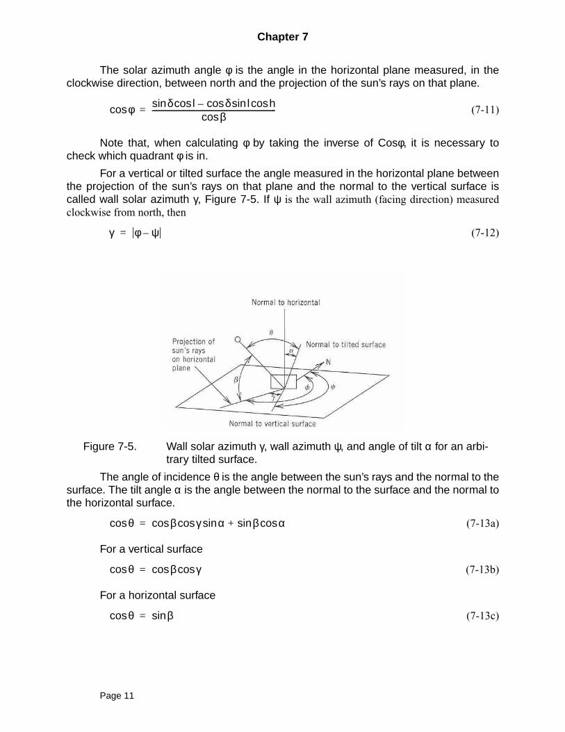
For a vertical or tilted surface the angle measured in the horizontal plane betweenthe projection of the sun’s rays on that plane and the normal to the vertical surface iscalled wall solar azimuth γ, Figure 7-5. If ψ is the wall azimuth (facing direction) measuredclockwise from north, then
(7-12)
Figure 7-5. Wall solar azimuth γ, wall azimuth ψ, and angle of tilt α for an arbi-trary tilted surface.
The angle of incidence θ is the angle between the sun’s rays and the normal to thesurface. The tilt angle α is the angle between the normal to the surface and the normal tothe horizontal surface.
(7-13a)
For a vertical surface
(7-13b)
For a horizontal surface
(7-13c)
φcos δ l δ l hcossincos–cossinβcos
-------------------------------------------------------------------=
γ φ ψ–=
θcos β γ α β αcossin+sincoscos=
θcos β γcoscos=
θcos βsin=
Page 11
Chapter 7
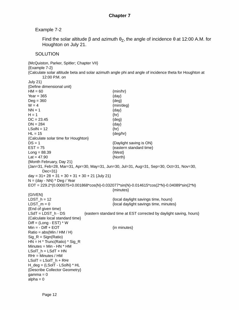
Example 7-2
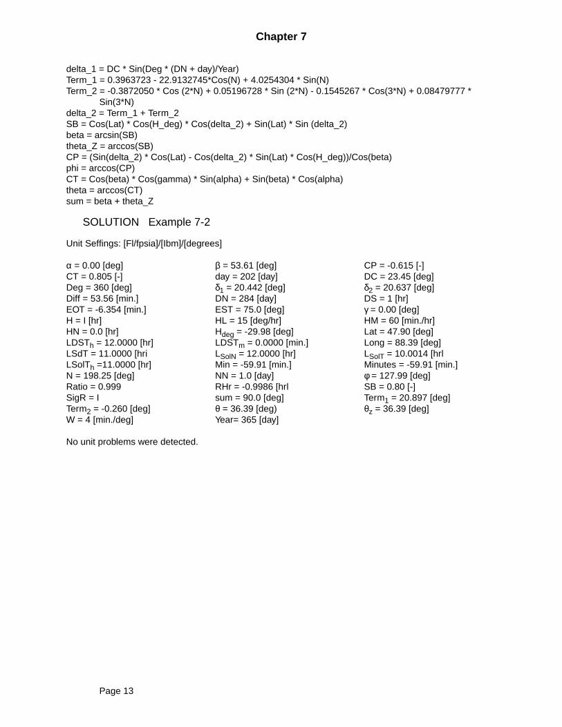
Find the solar altitude β and azimuth θZ, the angle of incidence θ at 12:00 A.M. forHoughton on July 21.
SOLUTION
McQuiston, Parker, Spitler; Chapter VIIExample 7-2Calculate solar altitude beta and solar azimuth angle phi and angle of incidence theta for Houghton at
12:00 P.M. onJuly 21Define dimensional unitHM = 60 min/hrYear = 365 dayDeg = 360 degW = 4 min/degNN = 1 dayH = 1 hrDC = 23.45 degDN = 284 dayLSolN = 12 hrHL = 15 deg/hrCalculate solar time for HoughtonDS = 1 Daylight saving is ONEST = 75 eastern standard timeLong = 88.39 WestLat = 47.90 NorthMonth February, Day 21Jan=31, Feb=28, Mar=31, Apr=30, May=31, Jun=30, Jul=31, Aug=31, Sep=30, Oct=31, Nov=30,
Dec=31day = 31+ 28 + 31 + 30 + 31 + 30 + 21 July 21N = (day - NN) * Deg / YearEOT = 229.2*(0.000075+0.001868*cos(N)-0.032077*sin(N)-0.014615*cos(2*N)-0.04089*sin(2*N)
minutesGIVENLDST_h = 12 local daylight savings time, hoursLDST_m = 0 local daylight savings time, minutesEnd of given timeLSdT = LDST_h - DS eastern standard time at EST corrected by daylight saving, hoursCalculate local standard timeDiff = (Long - EST) * WMin = - Diff + EOT in minutesRatio = abs(Min / HM / H)Sig_R = Sign(Ratio)HN = H * Trunc(Ratio) * Sig_RMinutes = Min - HN * HMLSolT_h = LSdT + HNRHr = Minutes / HMLSolT = LSolT_h + RHrH_deg = (LSolT - LSolN) * HLDescribe Collector Geometrygamma = 0alpha = 0
Page 12
Chapter 7
delta_1 = DC * Sin(Deg * (DN + day)/Year)Term_1 = 0.3963723 - 22.9132745*Cos(N) + 4.0254304 * Sin(N)Term_2 = -0.3872050 * Cos (2*N) + 0.05196728 * Sin (2*N) - 0.1545267 * Cos(3*N) + 0.08479777 *
Sin(3*N)delta_2 = Term_1 + Term_2SB = Cos(Lat) * Cos(H_deg) * Cos(delta_2) + Sin(Lat) * Sin (delta_2)beta = arcsin(SB)theta_Z = arccos(SB)CP = (Sin(delta_2) * Cos(Lat) - Cos(delta_2) * Sin(Lat) * Cos(H_deg))/Cos(beta)phi = arccos(CP)CT = Cos(beta) * Cos(gamma) * Sin(alpha) + Sin(beta) * Cos(alpha)theta = arccos(CT)sum = beta + theta_Z
SOLUTION Example 7-2
Unit Seffings: [Fl/fpsia]/[Ibm]/[degrees]
α = 0.00 [deg] β = 53.61 [deg] CP = -0.615 [-]CT = 0.805 [-] day = 202 [day] DC = 23.45 [deg]Deg = 360 [deg] δ1 = 20.442 [deg] δ2 = 20.637 [deg]Diff = 53.56 [min.] DN = 284 [day] DS = 1 [hr]EOT = -6.354 [min.] EST = 75.0 [deg] γ = 0.00 [deg]H = I [hr] HL = 15 [deg/hr] HM = 60 [min./hr]HN = 0.0 [hr] Hdeg = -29.98 [deg] Lat = 47.90 [deg]LDSTh = 12.0000 [hr] LDSTm = 0.0000 [min.] Long = 88.39 [deg]LSdT = 11.0000 [hri LSolN = 12.0000 [hr] LSolT = 10.0014 [hrlLSolTh =11.0000 [hr] Min = -59.91 [min.] Minutes = -59.91 [min.]N = 198.25 [deg] NN = 1.0 [day] φ = 127.99 [deg]Ratio = 0.999 RHr = -0.9986 [hrl SB = 0.80 [-]SigR = I sum = 90.0 [deg] Term1 = 20.897 [deg]Term2 = -0.260 [deg] θ = 36.39 [deg) θz = 36.39 [deg]W = 4 [min./deg] Year= 365 [day]
No unit problems were detected.
Page 13
Chapter 7
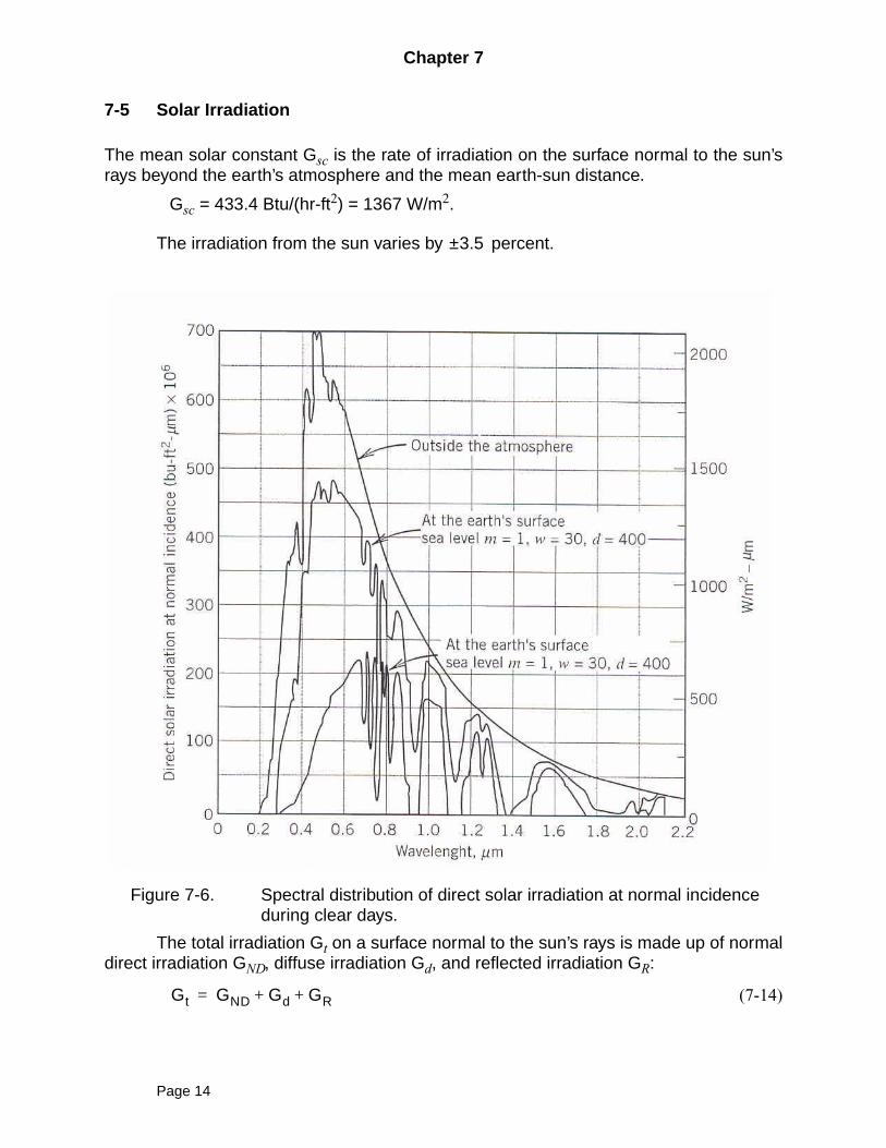
7-5 Solar Irradiation
The mean solar constant Gsc is the rate of irradiation on the surface normal to the sun’srays beyond the earth’s atmosphere and the mean earth-sun distance.
Gsc = 433.4 Btu/(hr-ft2) = 1367 W/m2.
The irradiation from the sun varies by percent.
Figure 7-6. Spectral distribution of direct solar irradiation at normal incidenceduring clear days.
The total irradiation Gt on a surface normal to the sun’s rays is made up of normaldirect irradiation GND, diffuse irradiation Gd, and reflected irradiation GR:
(7-14)
3.5±
Gt GND Gd GR+ +=
Page 14
Chapter 7
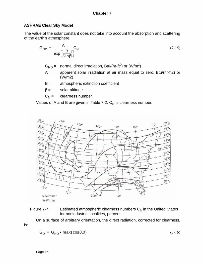
ASHRAE Clear Sky Model
The value of the solar constant does not take into account the absorption and scatteringof the earth’s atmosphere.
(7-15)
GND = normal direct irradiation, Btu/(hr-ft2) or (W/m2)
A = apparent solar irradiation at air mass equal to zero, Btu/(hr-ft2) or(W/m2)
B = atmospheric extinction coefficient
β = solar altitude
CN = clearness number
Values of A and B are given in Table 7-2. CN is clearness number.
Figure 7-7. Estimated atmospheric clearness numbers CN in the United Statesfor nonindustrial localities, percent.
On a surface of arbitrary orientation, the direct radiation, corrected for clearness,is:
(7-16)
GNDA
BSinβ-------------
exp-----------------------------CN=
GD GND max θcos 0,( )•=
Page 15
Chapter 7
where θ is the angle of incidence. The diffuse irradiation on a horizontal surface is givenby the use of factor C from Table 7-2. Read text for details.
(7-17)
Here C is the ratio of diffuse irradiation on a horizontal surface to direct normal irradia-tion. Refer to Figure 7-0. (not available in the text). C coefficient is taken from Table 7-2.
To evaluate the rate at which diffuse radiation Gdθ strikes a non vertical surface ona clear day, the following approximation can be made, (isotropic sky),
(7-18)
For a vertical surface,
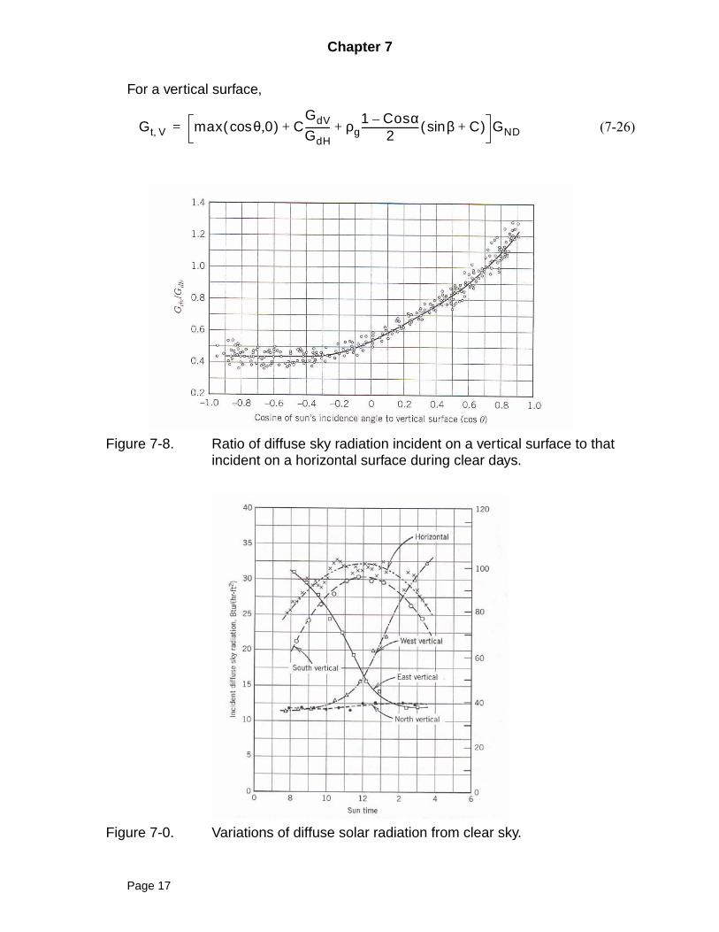
(7-21)
when ; otherwise . See Figure 7-8. Then for a vertical sur-face,
(7-22)
Energy reflected from ground and surroundings is approximated (diffuse reflec-tion)
(7-23)
GR = rate at which energy is reflected on to wall, Btu/(hr-ft2) or (W/m2)
GtH = rate at which the total radiation (direct plus diffuse) strikes the hori-zontal surface or ground in front of the wall, Btu/(hr-ft2) or (W/m2)
ρg = reflectance of ground or horizontal surface
Total solar radiation incident on a non vertical surface,
(7-25)
For a horizontal surface,
Gd CGND=
Gdθ CGNDFws CGND1 αcos+
2-----------------------
= =
GdV
GdH---------- 0.55 0.437 θ 0.313 θcos( )2
+cos+=
θcos 0.2–> GdV GdH⁄ 0.45=
Gdθ CGND
GdV
GdH----------=
GR GtHρg1 Cosα–( )
2-----------------------------=
Gt β, GD Gd GR+ +=
Gt β, max θ 0,cos( ) C1 Cosα+
2------------------------- ρg
1 Cosα–2
------------------------ β C+sin( )+ + GND=
Gt H, GD Gd+ max θ 0,cos( ) C1 Cosα+
2-------------------------+ GND= =
Page 16
Chapter 7
For a vertical surface,
(7-26)
Figure 7-8. Ratio of diffuse sky radiation incident on a vertical surface to thatincident on a horizontal surface during clear days.
Figure 7-0. Variations of diffuse solar radiation from clear sky.
Gt V, max θ 0,cos( ) CGdV
GdH---------- ρg
1 Cosα–2
------------------------ β C+sin( )+ + GND=
Page 17
Chapter 7
Example 7-3
Calculate the clear day direct, diffuse, and total solar radiation rate on a horizontalsurface for Houghton, July 21, at 12:00 P.M. Local time.
SOLUTION
McQuiston, Parker, Spitler; Chapter VIIExample 7-3Calculate the clear day direct, diffuse, and total solar radiation for Houghton at 12:00 P.M. onJuly 21Define dimensional unitHM = 60 min/hrYear = 365 dayDeg = 360 degW = 4 min/degNN = 1 dayH = 1 hrDC = 23.45 degDN = 284 dayLSolN = 12 hrHL = 15 deg/hrCalculate solar time for HoughtonDS = 1 Daylight saving is ONEST = 75 eastern standard timeLong = 88.39 WestLat = 47.90 NorthMonth February, Day 21Jan=31, Feb=28, Mar=31, Apr=30, May=31, Jun=30, Jul=31, Aug=31, Sep=30, Oct=31, Nov=30,
Dec=31day = 31+ 28 + 31 + 30 + 31 + 30 + 21 July 21N = (day - NN) * Deg / YearEOT = 229.2*(0.000075+0.001868*cos(N)-0.032077*sin(N)-0.014615*cos(2*N)-0.04089*sin(2*N))
minutesGIVENLDST_h = 12 local daylight savings time, hoursLDST_m = 0 local daylight savings time, minutesEnd of given timeLSdT = LDST_h - DS eastern standard time at EST corrected by daylight saving, hoursCalculate local standard timeDiff = (Long - EST) * WMin = - Diff + EOT in minutesRatio = abs(Min / HM / H)Sig_R = Sign(Ratio)HN = H * Trunc(Ratio) * Sig_RMinutes = Min - HN * HMLSolT_h = LSdT + HNRHr = Minutes / HMLSolT = LSolT_h + RHrH_deg = (LSolT - LSolN) * HLDescribe Collector Geometrygamma = 0alpha = 0delta_1 = DC * Sin(Deg * (DN + day)/Year)
Page 18
Chapter 7
Term_1 = 0.3963723 - 22.9132745*Cos(N) + 4.0254304 * Sin(N)Term_2 = -0.3872050 * Cos (2*N) + 0.05196728 * Sin (2*N) - 0.1545267 * Cos(3*N) + 0.08479777 *
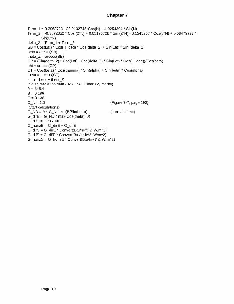
Sin(3*N)delta_2 = Term_1 + Term_2SB = Cos(Lat) * Cos(H_deg) * Cos(delta_2) + Sin(Lat) * Sin (delta_2)beta = arcsin(SB)theta_Z = arccos(SB)CP = (Sin(delta_2) * Cos(Lat) - Cos(delta_2) * Sin(Lat) * Cos(H_deg))/Cos(beta)phi = arccos(CP)CT = Cos(beta) * Cos(gamma) * Sin(alpha) + Sin(beta) * Cos(alpha)theta = arccos(CT)sum = beta + theta_ZSolar irradiation data - ASHRAE Clear sky modelA = 346.4B = 0.186C = 0.138C_N = 1.0 Figure 7-7, page 193Start calculationsG_ND = A * C_N / exp(B/Sin(beta)) normal directG_dirE = G_ND * max(Cos(theta), 0)G_difE = C * G_NDG_horizE = G_dirE + G_difEG_dirS = G_dirE * Convert(Btu/hr-ft^2, W/m^2)G_difS = G_difE * Convert(Btu/hr-ft^2, W/m^2)G_horizS = G_horizE * Convert(Btu/hr-ft^2, W/m^2)
Page 19
Chapter 7
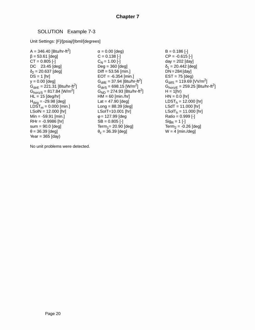
SOLUTION Example 7-3
Unit Settings: [F]/[psiaj/[Ibml/[degrees]
A = 346.40 [Btu/hr-ft2] α = 0.00 [deg) B = 0.186 [-]β = 53.61 [deg] C = 0.138 [-] CP = -0.615 [-]CT = 0.805 [-] CN = 1.00 [-] day = 202 [day]DC 23.45 [deg] Deg = 360 [deg] δ1 = 20.442 [deg]δ2 = 20.637 [deg] Diff = 53.56 [min.] DN = 284 [day]DS = 1 [hr] EOT = -6.354 [min.] EST = 75 [deg)y = 0.00 [deg] GdifE = 37.94 [Btu/hr-ft2] GdifS = 119.69 [VV/m2]GdirE = 221.31 [Btu/hr-ft2] GdirS = 698.15 [W/m2] GhorizE = 259.25 [Btu/hr-ft2]GhorizS = 817.84 [W/m2] GND = 274.93 [Btu/hr-ft2] H = 1[hr)HL = 15 [deg/hr] HM = 60 [min./hr] HN = 0.0 [hr]Hdeg = -29.98 [deg] Lat = 47.90 [deg] LDSTh = 12.000 [hr]LDSTm = 0.000 [min.] Long = 88.39 [deg] LSdT = 11.000 [hr]LSolN = 12.000 [hr] LSoIT=10.001 [hr] LSolTh = 11.000 [hr]Min = -59.91 [min.] φ = 127.99 [deg Ratio = 0.999 [-]RHr = -0.9986 [hr] SB = 0.805 [-] SigR = 1 [-]sum = 90.0 [deg] Term1= 20.90 [deg] Term2 = -0.26 [deg]θ = 36.39 [deg] θz = 36.39 [deg] W = 4 [min./deg]Year = 365 [day)
No unit problems were detected.
Page 20

Chapter 7
Example 7-4
For Houghton, MI calculate the total solar energy available on a south facing verti-cal window (surface) with no setback, at 12:00 P.M. local time, on July 21. Use theclear day mode.
SOLUTION
McQuiston, Parker, Spitler; Chapter VIIExample 7-4Calculate the clear day solar radiation on a south facing vertical surface for Houghton at 12:00 P.M. onJuly 21Define dimensional unitHM = 60 min/hrYear = 365 dayDeg = 360 degW = 4 min/degNN = 1 dayH = 1 hrDC = 23.45 degDN = 284 dayLSolN = 12 hrHL = 15 deg/hrCalculate solar time for HoughtonDS = 1 Daylight saving is ONEST = 75 eastern standard timeLong = 88.39 WestLat = 47.90 NorthMonth February, Day 21Jan=31, Feb=28, Mar=31, Apr=30, May=31, Jun=30, Jul=31, Aug=31, Sep=30, Oct=31, Nov=30,
Dec=31day = 31+ 28 + 31 + 30 + 31 + 30 + 21 July 21N = (day - NN) * Deg / YearEOT = 229.2*(0.000075+0.001868*cos(N)-0.032077*sin(N)-0.014615*cos(2*N)-0.04089*sin(2*N))
minutesGIVENLDST_h = 12 local daylight savings time, hoursLDST_m = 0 local daylight savings time, minutesEnd of given timeLSdT = LDST_h - DS eastern standard time at EST corrected by daylight saving, hoursCalculate local standard timeDiff = (Long - EST) * WLSolT_m = - Diff + EOT in minutesRatio = LSolT_m / HM/HHN = H * Trunc(Ratio)LSolT_h = LDST_h + HNMinutes = LSolT_m - HM * HNLSolT = LSolT_h + minutes / HMH_deg = (LSolT - LSolN) * HLDescribe Collector GeometryPSI = 180alpha = 90gamma = abs(phi - PSI)
Page 21
Chapter 7
delta_1 = DC * Sin(Deg * (DN + day)/Year)Term_1 = 0.3963723 - 22.9132745*Cos(N) + 4.0254304 * Sin(N)Term_2 = -0.3872050 * Cos (2*N) + 0.05196728 * Sin (2*N) - 0.1545267 * Cos(3*N) + 0.08479777 *
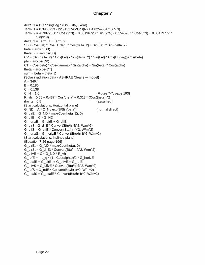
Sin(3*N)delta_2 = Term_1 + Term_2SB = Cos(Lat) * Cos(H_deg) * Cos(delta_2) + Sin(Lat) * Sin (delta_2)beta = arcsin(SB)theta_Z = arccos(SB)CP = (Sin(delta_2) * Cos(Lat) - Cos(delta_2) * Sin(Lat) * Cos(H_deg))/Cos(beta)phi = arccos(CP)CT = Cos(beta) * Cos(gamma) * Sin(alpha) + Sin(beta) * Cos(alpha)theta = arccos(CT)sum = beta + theta_ZSolar irradiation data - ASHRAE Clear sky modelA = 346.4B = 0.186C = 0.138C_N = 1.0 Figure 7-7, page 193R_vh = 0.55 + 0.437 * Cos(theta) + 0.313 * (Cos(theta))^2rho_g = 0.5 assumedStart calculations; Horizontal planeG_ND = A * C_N / exp(B/Sin(beta)) normal directG_dirE = G_ND * max(Cos(theta_Z), 0)G_difE = C * G_NDG_horizE = G_dirE + G_difEG_dirS= G_dirE * Convert(Btu/hr-ft^2, W/m^2)G_difS = G_difE * Convert(Btu/hr-ft^2, W/m^2)G_horizS = G_horizE * Convert(Btu/hr-ft^2, W/m^2)Start calculations; Inclined planeEquation 7-26 page 196G_dirEt = G_ND * max(Cos(theta), 0)G_dirSt = G_dirEt * Convert(Btu/hr-ft^2, W/m^2)G_difvE = C * G_ND * R_vhG_refE = rho_g * (1 - Cos(alpha))/2 * G_horizEG_totalE = G_dirEt + G_difvE + G_refEG_difvS = G_difvE * Convert(Btu/hr-ft^2, W/m^2)G_refS = G_refE * Convert(Btu/hr-ft^2, W/m^2)G_totalS = G_totalE * Convert(Btu/hr-ft^2, W/m^2)
Page 22
Chapter 7
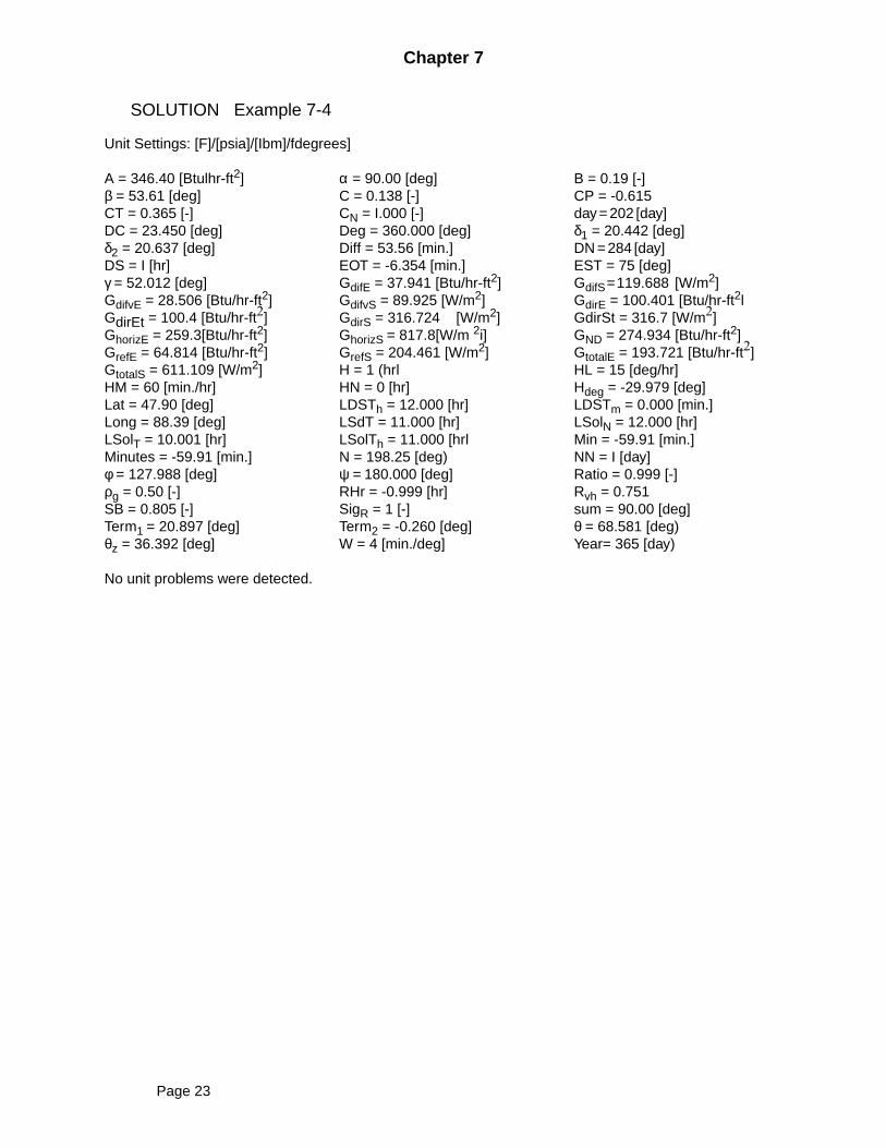
SOLUTION Example 7-4
Unit Settings: [F]/[psia]/[Ibm]/fdegrees]
A = 346.40 [Btulhr-ft2] α = 90.00 [deg] B = 0.19 [-]β = 53.61 [deg] C = 0.138 [-] CP = -0.615CT = 0.365 [-] CN = I.000 [-] day = 202 [day]DC = 23.450 [deg] Deg = 360.000 [deg] δ1 = 20.442 [deg]δ2 = 20.637 [deg] Diff = 53.56 [min.] DN = 284 [day]DS = I [hr] EOT = -6.354 [min.] EST = 75 [deg]γ = 52.012 [deg] GdifE = 37.941 [Btu/hr-ft2] GdifS=119.688 [W/m2]GdifvE = 28.506 [Btu/hr-ft2] GdifvS = 89.925 [W/m2] GdirE = 100.401 [Btu/hr-ft2lGdirEt = 100.4 [Btu/hr-ft2] GdirS = 316.724 [W/m2] GdirSt = 316.7 [W/m2]GhorizE = 259.3[Btu/hr-ft2] GhorizS = 817.8[W/m 2i] GND = 274.934 [Btu/hr-ft2]GrefE = 64.814 [Btu/hr-ft2] GrefS = 204.461 [W/m2] GtotalE = 193.721 [Btu/hr-ft2]GtotalS = 611.109 [W/m2] H = 1 (hrl HL = 15 [deg/hr]HM = 60 [min./hr] HN = 0 [hr] Hdeg = -29.979 [deg]Lat = 47.90 [deg] LDSTh = 12.000 [hr] LDSTm = 0.000 [min.]Long = 88.39 [deg] LSdT = 11.000 [hr] LSolN = 12.000 [hr]LSolT = 10.001 [hr] LSolTh = 11.000 [hrl Min = -59.91 [min.]Minutes = -59.91 [min.] N = 198.25 [deg) NN = I [day]φ = 127.988 [deg] ψ = 180.000 [deg] Ratio = 0.999 [-]ρg = 0.50 [-] RHr = -0.999 [hr] Rvh = 0.751SB = 0.805 [-] SigR = 1 [-] sum = 90.00 [deg]Term1 = 20.897 [deg] Term2 = -0.260 [deg] θ = 68.581 [deg)θz = 36.392 [deg] W = 4 [min./deg] Year= 365 [day)
No unit problems were detected.
Page 23
Chapter 7
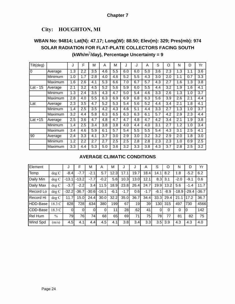
City: HOUGHTON, MI
WBAN No: 94814; Lat(N): 47.17; Long(W): 88.50; Elev(m): 329; Pres(mb): 974
SOLAR RADIATION FOR FLAT-PLATE COLLECTORS FACING SOUTH
(kWh/m2/day), Percentage Uncertainty = 9
AVERAGE CLIMATIC CONDITIONS
Tilt(deg) J F M A M J J A S O N D Yr
0 Average 1.3 2.2 3.5 4.6 5.5 6.0 6.0 5.0 3.6 2.3 1.3 1.1 3.6Minimum 1.0 1.7 2.8 4.0 4.6 5.2 5.5 4.3 3.0 2.0 1.1 0.7 3.3Maximum 1.6 2.6 4.1 5.3 6.6 7.0 6.7 5.7 4.3 2.7 1.6 1.3 3.8
Lat - 15 Average 2.1 3.2 4.5 5.2 5.6 5.9 6.0 5.5 4.4 3.2 1.9 1.6 4.1Minimum 1.3 2.4 3.5 4.3 4.7 5.0 5.4 4.6 3.3 2.6 1.3 1.0 3.7Maximum 2.8 4.0 5.5 6.3 6.9 6.9 6.8 6.3 5.6 3.9 2.6 2.1 4.4
Lat Average 2.3 3.5 4.7 5.2 5.3 5.4 5.6 5.2 4.4 3.4 2.1 1.8 4.1Minimum 1.4 2.5 3.5 4.2 4.3 4.6 5.1 4.4 3.3 2.7 1.3 1.0 3.7Maximum 3.2 4.4 5.8 6.3 6.5 6.3 6.3 6.1 5.7 4.2 2.9 2.3 4.4
Lat +15 Average 2.5 3.6 4.7 4.8 4.7 4.7 4.8 4.7 4.2 3.4 2.1 1.9 3.8Minimum 1.4 2.5 3.4 3.8 3.8 4.0 4.4 4.0 3.1 2.7 1.2 1.0 3.4Maximum 3.4 4.6 5.9 6.1 5.7 5.4 5.5 5.5 5.4 4.3 3.1 2.5 4.1
90 Average 2.4 3.3 4.1 3.7 3.0 2.9 3.0 3.2 3.2 2.9 2.0 1.8 3.0Minimum 1.2 2.2 2.7 2.7 2.5 2.5 2.8 2.8 2.3 2.3 1.0 0.9 2.5Maximum 3.3 4.4 5.3 5.0 3.6 3.2 3.3 3.8 4.3 3.7 2.8 2.5 3.2
Element J F M A M J J A S O N D Yr
Temp deg C -8.4 -7.7 -2.1 5.7 12.3 17.1 19.7 18.4 14.1 8.2 1.8 -5.2 6.2
Daily Min deg C -13.1 -13.2 -7.7 -0.2 5.6 10.3 13.0 12.1 8.3 3.1 -2.0 -9.1 0.6
Daily Max deg C -3.7 -2.2 3.4 11.5 18.9 23.8 26.4 24.7 19.9 13.2 5.6 -1.4 11.7
Record Lo deg C -32.2 -36.7 -30.6 -16.1 -6.1 -1.7 0.6 -1.7 -6.1 -8.9 -18.9 -29.4 -36.7
Record Hi deg C 11.7 15.0 24.4 30.0 32.2 35.0 36.7 34.4 33.3 29.4 21.1 17.2 36.7
HDD-Base 18.3 C 828 728 634 380 199 67 19 39 130 315 497 730 4566
CDD-Base 18.3 C 0 0 0 0 11 28 62 41 0 0 0 0 142
Rel Hum % 79 76 74 68 65 69 71 75 78 77 81 82 75
Wind Spd (m/s) 4.5 4.1 4.4 4.5 4.1 3.8 3.4 3.3 3.5 3.9 4.3 4.3 4.0
Page 24
Chapter 7
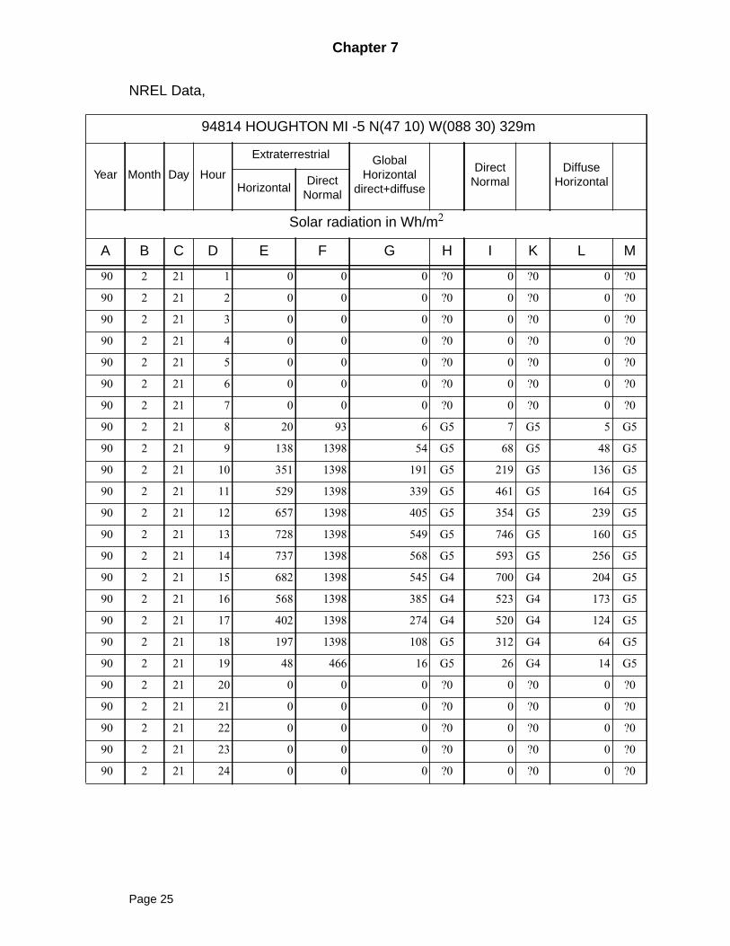
NREL Data,
94814 HOUGHTON MI -5 N(47 10) W(088 30) 329m
Year Month Day Hour
Extraterrestrial GlobalHorizontal
direct+diffuse
DirectNormal
DiffuseHorizontalHorizontal
DirectNormal
Solar radiation in Wh/m2
A B C D E F G H I K L M
90 2 21 1 0 0 0 ?0 0 ?0 0 ?0
90 2 21 2 0 0 0 ?0 0 ?0 0 ?0
90 2 21 3 0 0 0 ?0 0 ?0 0 ?0
90 2 21 4 0 0 0 ?0 0 ?0 0 ?0
90 2 21 5 0 0 0 ?0 0 ?0 0 ?0
90 2 21 6 0 0 0 ?0 0 ?0 0 ?0
90 2 21 7 0 0 0 ?0 0 ?0 0 ?0
90 2 21 8 20 93 6 G5 7 G5 5 G5
90 2 21 9 138 1398 54 G5 68 G5 48 G5
90 2 21 10 351 1398 191 G5 219 G5 136 G5
90 2 21 11 529 1398 339 G5 461 G5 164 G5
90 2 21 12 657 1398 405 G5 354 G5 239 G5
90 2 21 13 728 1398 549 G5 746 G5 160 G5
90 2 21 14 737 1398 568 G5 593 G5 256 G5
90 2 21 15 682 1398 545 G4 700 G4 204 G5
90 2 21 16 568 1398 385 G4 523 G4 173 G5
90 2 21 17 402 1398 274 G4 520 G4 124 G5
90 2 21 18 197 1398 108 G5 312 G4 64 G5
90 2 21 19 48 466 16 G5 26 G4 14 G5
90 2 21 20 0 0 0 ?0 0 ?0 0 ?0
90 2 21 21 0 0 0 ?0 0 ?0 0 ?0
90 2 21 22 0 0 0 ?0 0 ?0 0 ?0
90 2 21 23 0 0 0 ?0 0 ?0 0 ?0
90 2 21 24 0 0 0 ?0 0 ?0 0 ?0
Page 25
Chapter 7
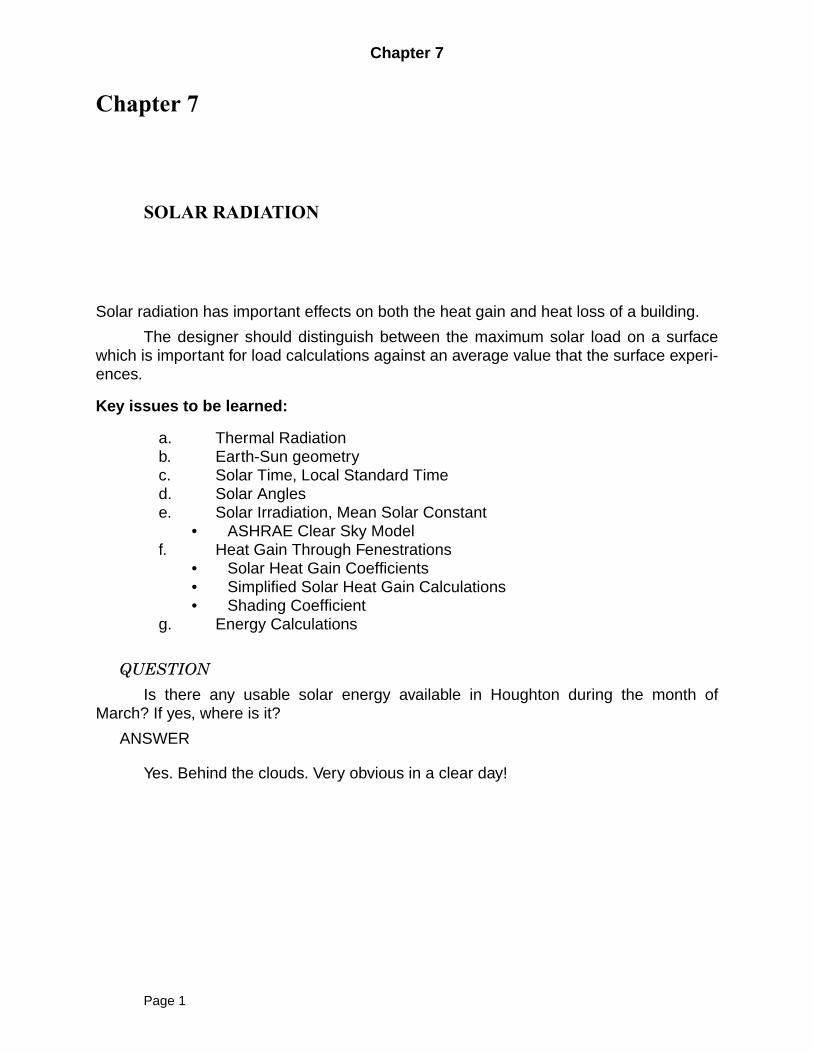
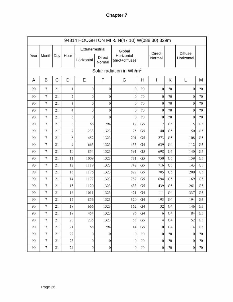
94814 HOUGHTON MI -5 N(47 10) W(088 30) 329m
Year Month Day Hour
Extraterrestrial GlobalHorizontal
(dirct+diffuse)
DirectNormal
DiffuseHorizontalHorizontal
DirectNormal
Solar radiation in Wh/m2
A B C D E F G H I K L M
90 7 21 1 0 0 0 ?0 0 ?0 0 ?0
90 7 21 2 0 0 0 ?0 0 ?0 0 ?0
90 7 21 3 0 0 0 ?0 0 ?0 0 ?0
90 7 21 4 0 0 0 ?0 0 ?0 0 ?0
90 7 21 5 0 0 0 ?0 0 ?0 0 ?0
90 7 21 6 66 794 17 G5 17 G5 15 G5
90 7 21 7 233 1323 75 G5 140 G5 50 G5
90 7 21 8 452 1323 201 G5 273 G5 108 G5
90 7 21 9 663 1323 433 G4 639 G4 112 G5
90 7 21 10 854 1323 591 G5 698 G5 140 G5
90 7 21 11 1009 1323 731 G5 750 G5 159 G5
90 7 21 12 1119 1323 748 G5 716 G5 143 G5
90 7 21 13 1176 1323 827 G5 705 G5 200 G5
90 7 21 14 1177 1323 787 G5 694 G5 169 G5
90 7 21 15 1120 1323 633 G5 439 G5 261 G5
90 7 21 16 1011 1323 421 G4 111 G4 337 G5
90 7 21 17 856 1323 320 G4 193 G4 194 G5
90 7 21 18 666 1323 162 G4 32 G4 146 G5
90 7 21 19 454 1323 86 G4 6 G4 84 G5
90 7 21 20 235 1323 53 G5 4 G4 52 G5
90 7 21 21 68 794 14 G5 0 G4 14 G5
90 7 21 22 0 0 0 ?0 0 ?0 0 ?0
90 7 21 23 0 0 0 ?0 0 ?0 0 ?0
90 7 21 24 0 0 0 ?0 0 ?0 0 ?0
Page 26
Chapter 7
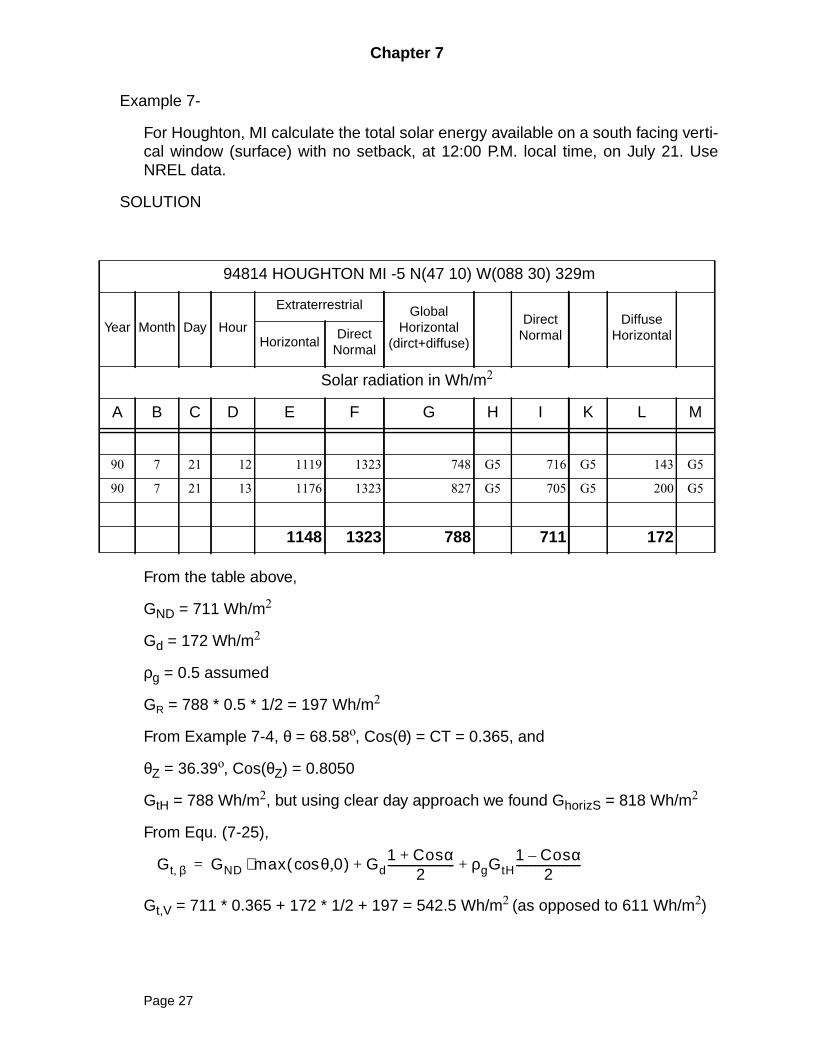
Example 7-
For Houghton, MI calculate the total solar energy available on a south facing verti-cal window (surface) with no setback, at 12:00 P.M. local time, on July 21. UseNREL data.
SOLUTION
From the table above,
GND = 711 Wh/m2
Gd = 172 Wh/m2
ρg = 0.5 assumed
GR = 788 * 0.5 * 1/2 = 197 Wh/m2
From Example 7-4, θ = 68.58o, Cos(θ) = CT = 0.365, and
θZ = 36.39o, Cos(θZ) = 0.8050
GtH = 788 Wh/m2, but using clear day approach we found GhorizS = 818 Wh/m2
From Equ. (7-25),
Gt,V = 711 * 0.365 + 172 * 1/2 + 197 = 542.5 Wh/m2 (as opposed to 611 Wh/m2)
94814 HOUGHTON MI -5 N(47 10) W(088 30) 329m
Year Month Day Hour
Extraterrestrial GlobalHorizontal
(dirct+diffuse)
DirectNormal
DiffuseHorizontalHorizontal
DirectNormal
Solar radiation in Wh/m2
A B C D E F G H I K L M
90 7 21 12 1119 1323 748 G5 716 G5 143 G5
90 7 21 13 1176 1323 827 G5 705 G5 200 G5
1148 1323 788 711 172
Gt β, GND max θ 0,cos( )⋅ Gd1 Cosα+
2------------------------- ρgGtH
1 Cosα–2
------------------------+ +=
Page 27
Chapter 7
7-6 Heat Gain Through Fenestrations
The term fenestration refers to any glazed aperture in a building envelope.
• Glazing material, either glass or plastic• Framing, mullions, muntin, and dividers• External shading devices• Internal shading devices• Integral (between-glass) shading system
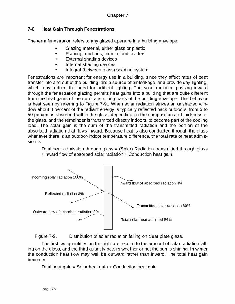
Fenestrations are important for energy use in a building, since they affect rates of beattransfer into and out of the building, are a source of air leakage, and provide day-lighting,which may reduce the need for artificial lighting. The solar radiation passing inwardthrough the fenestration glazing permits heat gains into a building that are quite differentfrom the heat gains of the non transmitting parts of the building envelope. This behavioris best seen by referring to Figure 7-9.. When solar radiation strikes an unshaded win-dow about 8 percent of the radiant energy is typically reflected back outdoors, from 5 to50 percent is absorbed within the glass, depending on the composition and thickness ofthe glass, and the remainder is transmitted directly indoors, to become part of the coolingload. The solar gain is the sum of the transmitted radiation and the portion of theabsorbed radiation that flows inward. Because heat is also conducted through the glasswhenever there is an outdoor-indoor temperature difference, the total rate of heat admis-sion is
Total heat admission through glass = (Solar) Radiation transmitted through glass+Inward flow of absorbed solar radiation + Conduction heat gain.
Figure 7-9. Distribution of solar radiation falling on clear plate glass.
The first two quantities on the right are related to the amount of solar radiation fall-ing on the glass, and the third quantity occurs whether or not the sun is shining. In winterthe conduction heat flow may well be outward rather than inward. The total heat gainbecomes
Total heat gain = Solar heat gain + Conduction heat gain
Inward flow of absorbed radiation 4%
Transmitted solar radiation 80%
Total solar heat admitted 84%
Incoming solar radiation 100%
Reflected radiation 8%
Outward flow of absorbed radiation 8%
Page 28
Chapter 7
The inward flow of absorbed solar radiation and the conduction heat gain are notindependent, but they are often approximated as if they are. In this case, the conductionheat gain per unit area is simply the product of the overall coefficient of heat transfer Ufor the existing fenestration and the outdoor-indoor temperature difference (To - Ti). Val-ues of U for a number of widely used glazing systems are given in Table 5-5. Additionalvalues may be found in the ASHRAE Handbook, Fundamentals Volume (5) and in manu-facturers’ literature. More detailed approach, which accounts for the conduction heat gainsimultaneously with the inward flowing absorbed solar radiation will be seen later in Sec-tion 8-9, Interior Surface Heat Balance-Opaque Surfaces.
Solar Heat Gain Coefficients
The heat gain through even the simplest window is complicated by the fact that the win-dow is finite in size, it is framed, and the sunlight striking it does so at varying anglesthroughout the day. To fully take all of the complexities into account requires the use ofnot only spectral methods (using monochromatic radiation properties) but also the angu-lar radiation characteristics involved. The equations required become quite complex, therequired properties are sometimes difficult to determine. and lengthy computer calcula-tions are involved. Early steps in this process are described by Harrison and van Won-deren (Ref. 10) and by Arasteh (Ref. 11). For a more complete description of the methodrefer to the fenestration chapter in the most recent edition of the ASHRAE Handbook,Fundamentals Volume (5).
A simplified method utilizes a spectrally-averaged solar heat gain coefficient(SHGC), the fraction of the incident irradiance (incident solar energy) that enters theglazing and becomes heat gain:
(7-27)
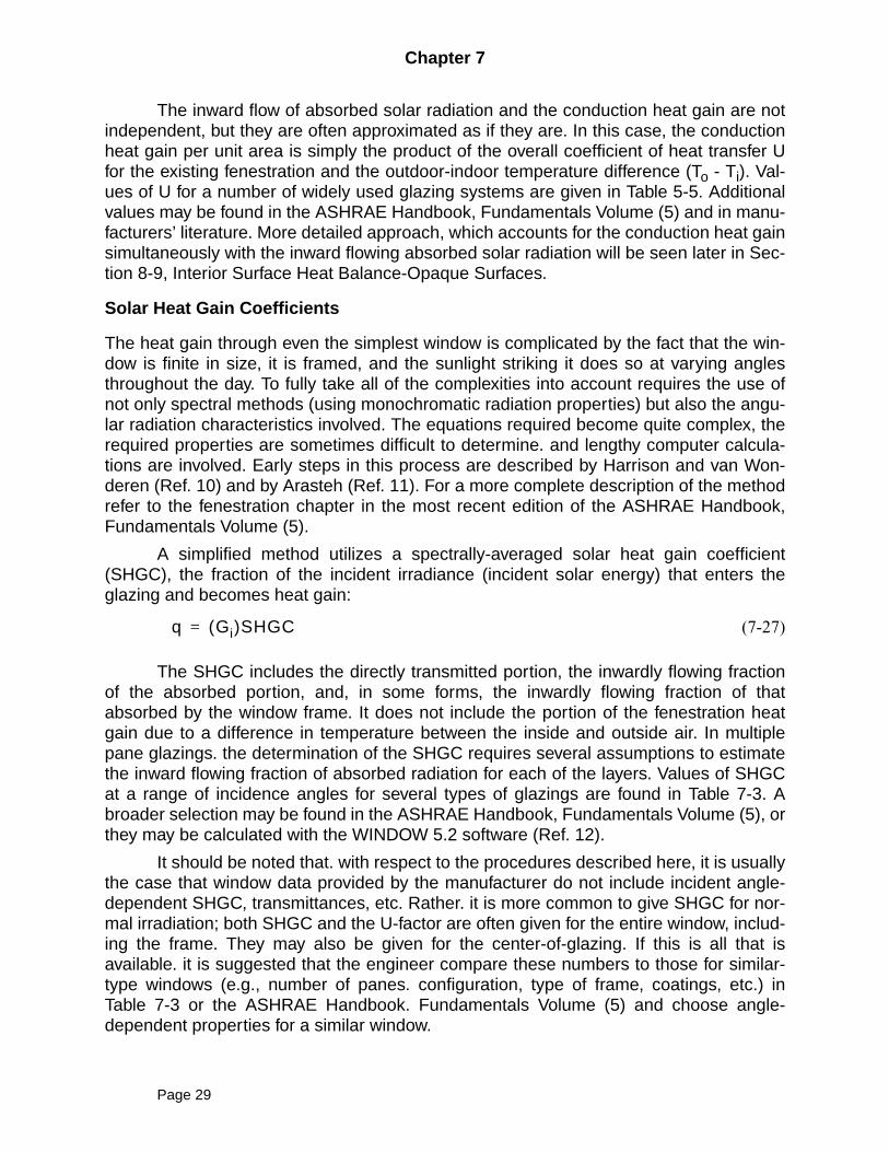
The SHGC includes the directly transmitted portion, the inwardly flowing fractionof the absorbed portion, and, in some forms, the inwardly flowing fraction of thatabsorbed by the window frame. It does not include the portion of the fenestration heatgain due to a difference in temperature between the inside and outside air. In multiplepane glazings. the determination of the SHGC requires several assumptions to estimatethe inward flowing fraction of absorbed radiation for each of the layers. Values of SHGCat a range of incidence angles for several types of glazings are found in Table 7-3. Abroader selection may be found in the ASHRAE Handbook, Fundamentals Volume (5), orthey may be calculated with the WINDOW 5.2 software (Ref. 12).
It should be noted that. with respect to the procedures described here, it is usuallythe case that window data provided by the manufacturer do not include incident angle-dependent SHGC, transmittances, etc. Rather. it is more common to give SHGC for nor-mal irradiation; both SHGC and the U-factor are often given for the entire window, includ-ing the frame. They may also be given for the center-of-glazing. If this is all that isavailable. it is suggested that the engineer compare these numbers to those for similar-type windows (e.g., number of panes. configuration, type of frame, coatings, etc.) inTable 7-3 or the ASHRAE Handbook. Fundamentals Volume (5) and choose angle-dependent properties for a similar window.
q Gi( )SHGC=
Page 29
Chapter 7
Unfortunately the SHGC approach does not directly allow for separate treatmentof transmitted and absorbed components of the solar heat gain. However, for detailedcooling load calculations, it is desirable to be able to separate the two components. For-tunately, new data (transmittance and layer-by-layer absorptance) available in Table 7-3and the ASHRAE Handbook. Fundamentals Volume (5) and calculable for any windowwith the WINDOW 5.2 software (Ref. 12) do allow a separate estimation of the transmit-ted and absorbed components. Two procedures are described below: a “simplified” pro-cedure that utilizes SHGC and, hence. blends together the transmitted and absorbedcomponents. and a “detailed” procedure that estimates them separately.
The procedure may be described from “outside to inside.”
• First, the direct and diffuse solar radiation incident on an unshadedsurface with the same orientation as the window is calculated with theprocedures described in Section 7-3 through 7-5.
• Second. the effects of external shading on the solar radiation incidenton the window are determined.
• Third. the solar radiation transmitted and absorbed is analyzed for thewindow. assuming no internal shading.
• Fourth. If there is internal shading, its effects on the total amount ofsolar radiation transmitted and absorbed are calculated.
For the third and fourth parts, both simplified and detailed procedures aredescribed.
Page 30
Chapter 7
Table 7-3 Solar Heat Gain Coefficients (SHGC), Solar Transmittance (T), FrontReflectance (Rf), Back Reflectance (Rb), and Layer Absorptances (Afn)for Glazing Window Systems
Triple glazing data have been excluded. See text for details.
Source: ASHRAE Handbook, Fundamentals Volume, American Society of Heating, Refrigerating, and Air-Conditioning Engineers, Inc., 2001.
Total Window
SHGC at
Center-of-Glazing Properties Normal Incidence
Incidence Angles AluminumOther
Frames
IDGlassThick.
in. (mm) Nor
mal
0.00
40.0
50.0
60.0
70.0
80.0
Diff
use
Ope
rabl
e
Fix
ed
Ope
rabl
e
Fix
ed
la 1/8 (3.2) Uncoated Single SHGC 0.86 0.84 0.82 0.78 0.67 0.42 0.78 0.75 0.78 0.64 0.75
Glazing, CLR T 0.83 0.82 0.80 0.75 0,64 0.39 0.75
Rf 0.08 0.08 0.10 0.14 0.25 0.51 0.14
Rb 0.08 0.08 0.10 0.14 0.25 0.51 0.14
A 0-09 0.10 0.10 0.11 0.11 0.11 0.10
5a 1/8 (3.2) Uncoated Double SHGC 0.76 0.74 0.71 0.64 0.50 0.26 0.66 0.67 0.69 0.56 0.66
Glazing, CLR CLR T 0.70 0.68 0.65 0.58 0.44 0.21 0.60
Rf 0.13 0.14 0.16 0.23 0.36 0.61 0.21
Rb 0.13 0.14 0.16 0.23 0.36 0.61 0.21
Af, 0.10 0.11 0.11 0.12 0.13 0.13 0.11
A4 0.07 0.08 0.08 0.08 0.07 0.05 0.07
5b 1/4 (6.4) Uncoated Double SfiGC 0.70 0.67 0.64 0.58 0.45 0.23 0.60 0.61 0.63 0.52 0.61
Glazing, CLR CLR T 0.61 0.58 0.55 0.48 0.36 0.17 0.51
Rf 0.11 0.12 0.15 0.20 0.33 0.57 0.18
Rb 0.11 0.12 0.15 0.20 0.33 0.57 0.18
At, 0.17 0.18 0.19 0.20 0.21 0.20 0.19
A4 0.11 0.12 0.12 0.12 0.10 0.07 0.11
21a 1/8 (3.2) Low-e Double SfiOC 0.65 0.64 0.62 0.56 0.43 0.23 0.57 0.48 0.50 0.41 0.47
Giazing, e = 0. I on T 0.59 0.56 0.54 0.48 0.36 0.18 0.50
surface 2, LE CLR Rf 0.15 0.16 0.18 0.24 0.37 0.61 0.22
Rb 0.17 0.18 0.20 0.26 0.38 0.61 0.24
bb 0.20 0.21 0.21 0.21 0.20 0.16 0.20
cc 0.07 0.07 0.08 0.08 0.07 0.05 0.07
21c 118(3.2)
Low-e Double SHGC 0.60 0.58 0.56 0.51 0.40 0.22 0.52 0.53 0.55 0.45 0.53
Glazing, e = 0. I on T 0.48 0.45 0.43 0.37 0.27 0.13 0.40
surface 3, CLR LE Rf 0.26 0.27 0.28 0.32 0.42 0.62 0.31
Rb 0.24 0.24 0.26 0.29 0.38 0.58 0.28
Af 0.12 0.13 0.14 0.14 0.15 0.15 0.13
A4 0.14 0.15 0.15 0.16 0.16 0.10 0.15
Page 31
Chapter 7
External Shading
A fenestration may be shaded by roof overhangs. awnings. side fins or other partsof the building, trees. shrubbery, or another buildIng. External shading of fenestrations iseffective in reducing solar heat gain to a space and may produce reductions of up to 80percent. In order to determine the solar radiation Incident on the fenestration, it is neces-sary to determine the area of the fenestration that is shaded and the area that is sunlit.The areas on which external shade falls can be calculated from the geometry of theexternal objects creating the shade and from knowledge of the sun angles for that partic-ular time and location. It is generally assumed that shaded areas have no incident directradiation, but that the diffuse irradiation incident on the shaded area is the same as thaton the sunlit area. This is a conservative approximation, if more accuracy is desired, itwould be possible to refine the configuration factor to the sky .
In general, shading devices may have almost any geometry. A general algorithmfor determining shading caused by any shape with any orientation is given by Walton(Ref. 13). Procedures for other specific shapes are given in references reviewed bySpitler (Ref. 14). Here, we will describe a procedure suitable for horizontal or verticalshading devices that are long enough to cast a shadow along the entire fenestration.
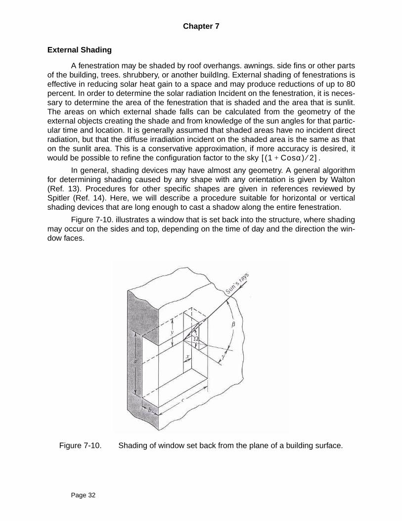
Figure 7-10. illustrates a window that is set back into the structure, where shadingmay occur on the sides and top, depending on the time of day and the direction the win-dow faces.
Figure 7-10. Shading of window set back from the plane of a building surface.
1 Cosα+( ) 2⁄[ ]
Page 32
Chapter 7
It can be shown that the dimensions x and y are given by
(7-28)
(7-29)
where:
(7-30)
Here:
β = sun's altitude angle
γ = wall solar azimuth angle = |φ - ψ|
φ =solar azimuth measured clockwise from north
ψ = wall azimuth, measured clockwise from north
If γ is greater than 90 deg, the surface is in the shade. Equations (7-29) and (7-30) canbe used for an overhang at the top and perpendicular to the window provided that theoverhang- is wide enough for the shadow to extend completely across the window.
x bTanγ=
y bTanΩ=
TanΩ TanβCosγ--------------=
Page 33
Chapter 7
Example 7-5
A 4 ft high x 5 ft wide double-glazed window faces southwest (ψ = 225). The win-dow has a frame with width of 1.5 in. around the outside edge. (The actual glazedarea has dimensions of 3.75 ft high x 4.75 ft wide.) The top of the window has a 2ft overhang that extends a great distance on each side of the window. Computethe shaded area of the frame and glazing on July 21 (n = 202) at 3:00 PM. solartime (h = 45), at l = 40 deg N latitude.
SOLUTION
Note
4x5 = 20 ft2, 3.75x4.75 = 17.81 ft2, the difference is 2. 1875 ft2 yet the text indi-cates the frame area to be 2.63 ft2. We will stay with that value to be consistentwith the text. Remember,
, β = 47.0deg
, φ = 256.6deg
γ =abs(φ - ψ) = 31.6 deg
With (1/8 in) set back from the edge of the frame actual frame area needs to beincreased by the following amount to
ft2.
This info will be used later.
ft
ft
The shading on the window is illustrated in Figure 7-11. For the shaded area ofthe frame,
ft2
The sunlit portion of the frame has an area of
ft2
For the shaded and sunlit areas the glazing,
ft2
ft2
βsin l δ l δsinsin+coscoshcos=
φcos δ l δ l hcossincos–cossinβcos
-------------------------------------------------------------------=
2.63 1 8⁄( ) 12⁄( )x2x 3.75 4.75+( )+ 2.8071 2.81∼=
x bTanγ 2Tan 31.6( ) 1.23= = =
y bTanβCosγ-------------- 2
Tan 47( )Cos 31.6( )---------------------------- 2.52= = =
Ash f, 2.52x0.125x2 0.125x4.75+ 1.22= =
Asl f, 2.63 1.22– 1.41= =
Ash g, 2.52 0.125–( )4.75 11.38= =
Ash g, 17.8125 11.3763– 6.4363= =
Page 34
Chapter 7
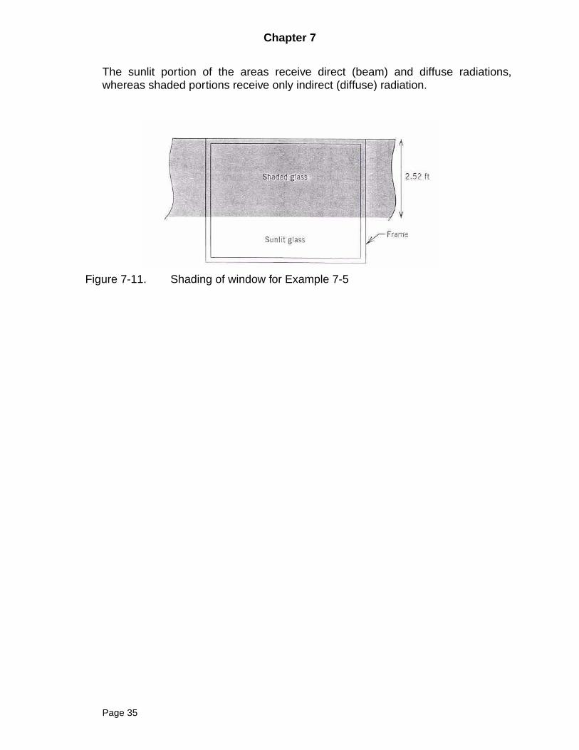
The sunlit portion of the areas receive direct (beam) and diffuse radiations,whereas shaded portions receive only indirect (diffuse) radiation.
Figure 7-11. Shading of window for Example 7-5
Page 35
Chapter 7
Transmission and Absorption of Fenestration Without Internal Shading, Simplified
In order to determine solar heat gain with the simplified procedure, it is assumed that,based on the procedures described above,
• the direct irradiance on the surface (GD),• the diffuse irradiance on the surface (Gd),• the sunlit area of the glazing (Asl,g),• the sunlit area of the frame (Asl,f)• the areas of the glazing (Ag) and frame (Af)• and the basic window properties must be known.
The solar heat gain coefficient of the frame (SHGCf) may be estimated as
(7-31)
where
• Aframe is the projected area of the frame element, and• Asurf is the actual surface area.• is the solar absorptivity of the exterior frame surface (see Table 7-1).• Uf is the U-factor of the frame element (see Table 5-6);• hf is the overall exterior surface conductance (see Table 5-2a).• If other frame elements like dividers exist, they may be analyzed in the
same way.
The solar heat gain coefficient of the glazing may be taken from Table 7-3 for aselection of sample windows. For additional windows, the reader should consult theASHRAE Handbook, Fundamentals Volume (5) as well as the WINDOW software (Ref.12).
There are actually two solar heat gain coefficients of interest, one for direct radia-tion at the actual incidence angle (SHGCgD) and a second for diffuse radiation(SHGCgd). SHGCgD may be determined from Table 7-3 by linear interpolation. Values ofSHGCgd may be found in the column labeled “Diffuse.”
Once the values of SHGCf, SHGCgD and SHGCgd have been determined, thetotal solar heat gain of the window may be determined by applying direct radiation to thesunlit portion of the fenestration and direct and diffuse radiation to the entire fenestration:
(7-32)
To compute the total heat gain through the window, the conduction heat gain must beadded, which is estimated as
(7-33)
SHGCf α fs UfAframe
hfAsurf----------------------
=
α fs
qSHG SHGCgDAsl g, SHGCfAsl f,+[ ] GDθ SHGCgdAg SHGCfAf+[ ] Gdθ+=
qCHG U To Ti–( )=
Page 36
Chapter 7
where U for the fenestration may be taken from Table 5-5, the ASHRAE Handbook, Fun-damentals Volume (5), or the WINDOW 5.2 software (Ref. 12); and (To - Ti) is the out-door-indoor temperature difference.
Transmission and Absorption of Fenestration Without Internal Shading, Detailed
Incorporates transmitted solar irradiation and that portion of absorbed radiationthat is transmitted inward. EXCLUDED.
Page 37
Chapter 7
Example 7-6
Consider the 4 ft high x 5 ft wide, fixed (inoperable) double-glazed window, facingsouthwest from Example 7-5. The glass thickness is 1/8 In., the two panes areseparated by a 1/4 in. air space, and surface 2 (the inside of the outer pane) has alow-e coating with an emissivity of 0.1. The frame, painted with white acrylic paint,is aluminum with thermal break; the spacer is insulated. The outer layer of glaz-ing, is set back from the edge of the frame 1/8 in. On July 21 at 3:00 P.M. solartime at 40 deg N latitude, the incident angle is 54.5 deg, the incident direct irradia-tion is 155.4 Btu/hr-ft2, and the incident diffuse irradiation is 60.6 Btu/hr-ft2. Findthe solar heat gain of the window.
SOLUTION
The window corresponds to ID 21a in Table 7-3.
• SHGCgD is found to be 0.59; SHGCgd is 0.57.• The frame U-factor may be determined from Table 5-6 to be 1.04 Btu/hr-
ft2-F.• The solar absorptance of white acrylic paint, from Table 7- 1, is 0.26.• The outside surface conductance, from Table 5-2, is 4.0 Btu/hr-ft2-F.• The projected area of the frame is 2.63 ft2; the actual surface area, 2.81
ft2, is slightly larger, because the glass is set back 1/8 in. from the outeredge of the frame.
• SHGCf may be estimated with Eq. (7-31)
Then, from Eq. (7-32), the solar heat gain may be estimated:
Btu/hr.
SHGC 0.261.04 2.63×4.0 2.81×
----------------------------- 0.063= =
q 0.59 6.43 0.063 1.41×+×[ ] 155.4 0.57x17.81 0.063x2.63+[ ] 60.6+ 1228.6= =
Page 38
Chapter 7
Transmission and Absorption of Fenestration with Internal Shading, Simplified
Internal shading, such as Venetian blinds, roller shades, and draperies, further compli-cate the analysis of solar heat gain. Shading devices are successful in reducing solarbeat gain to the degree that solar radiation is reflected back out through the window.Solar radiation absorbed by the shading device will be quickly released to the room. Lim-ited availability of data precludes a very detailed analysis, and angle of incidence depen-dence is usually neglected. To calculate the effect of internal shading, it is convenient torecast Eq. (7-2) to separate the beat gain due to the glazing and frame. Then, the solarradiation transmitted and absorbed by the glazing is multiplied by an interior solar attenu-ation coefficient (IAC)
(7-41)
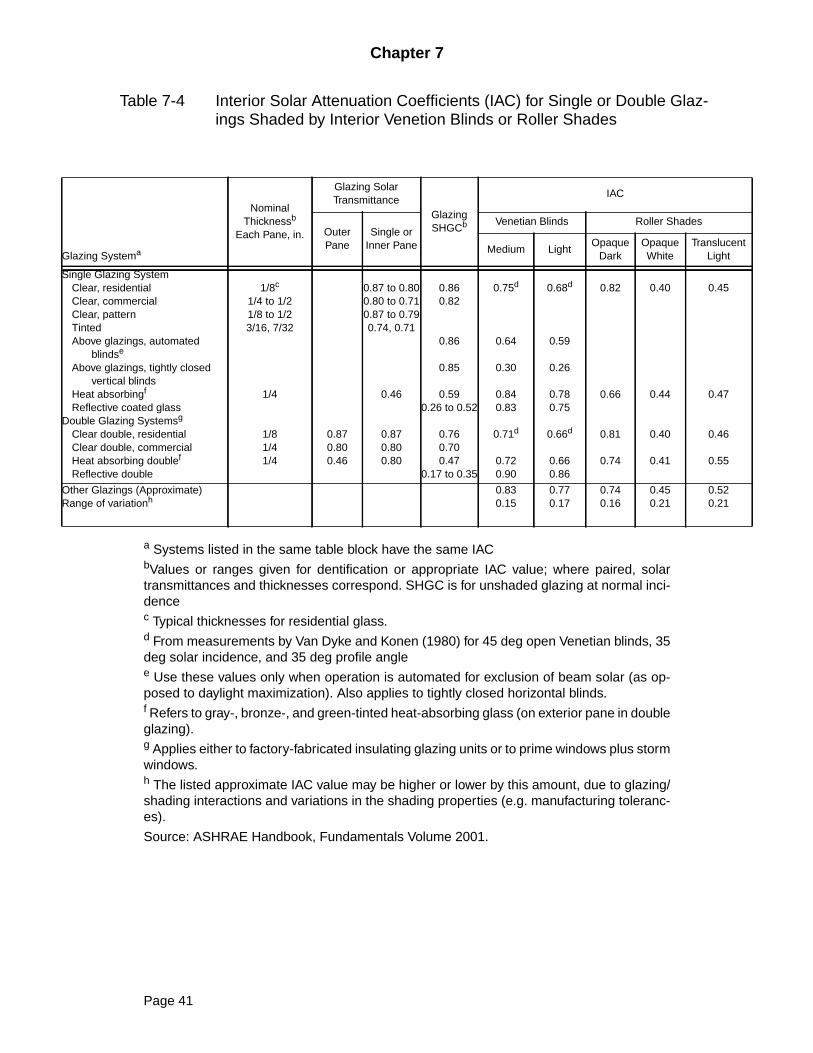
Interior solar attenuation coefficients for Venetian blinds and roller shades may be foundin Table 7-4. Since the effect of the shading device depends partly on the window, thevalues of IAC given in this table depend on both the shading device and the type of glaz-ing, characterized by configuration and SHGC at normal incidence.
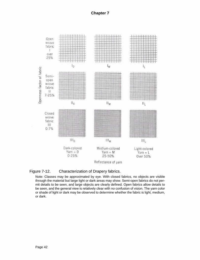
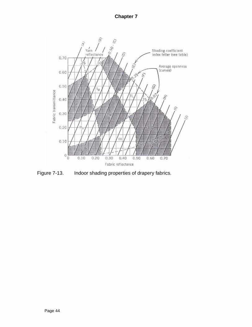
For draperies, the IAC depends on the color and weave of the fabric. Althoughother variables also have an effect, reasonable correlation has been obtained using onlycolor and openness of the weave. Figure 7-12. may be used to help characterize open-ness.
• Openness is classified as open, I; semiopen, II; and closed, III;• Color is classified as dark, D; medium, M; and light, L; A light-colored,
closed-weave material would then be classified IIIL.
Once the category has been established, an index letter (A to J) may be read andused to determine the IAC from Table 7-5. For any category, several index letters may bechosen, and judgment based on the color and weave is required in making a final selec-tion.
Transmission and Absorption of Fenestration with Internal Shading, Detailed
EXCLUDED
qSHG SHGCfAsl f, GDθ SHGCfAfGdθ+[ ] +=
SHGCgDAsl g, GDθ SHGCgdAgGdθ+[ ] IAC=
Page 39
Chapter 7
Example 7-8
If an opaque white roller shade were added to the window in Example 7-6, what would bethe effect on the solar heat gain?
SOLUTION
From Table 7-4 the interior solar attenuation coefficient for an opaque white roller shadeinstalled on a residential double-pane Window is 0.41. From Eq. (7-41). the resultingsolar heat gain may be calculated:
Btu/hr
This is 42 percent of the solar beat gain without the shade; the heat transfer through theframe is not affected by the shade, so the reduction in the total heat gain is slightly lessthan might be inferred from the IAC.
qSHG 0.063x1.41x155.4 0.063x2.63x60.6+[ ] +=
0.59x6.43x155.4 0.57x17.81x60.6+[ ] 0.41 493.9=
Page 40
Chapter 7
Glazient
SinglCleCleCleTinAb
Ab
HeRe
DoubCleCleHeRe
OtheRang
Table 7-4 Interior Solar Attenuation Coefficients (IAC) for Single or Double Glaz-ings Shaded by Interior Venetion Blinds or Roller Shades
a Systems listed in the same table block have the same IACbValues or ranges given for dentification or appropriate IAC value; where paired, solartransmittances and thicknesses correspond. SHGC is for unshaded glazing at normal inci-dencec Typical thicknesses for residential glass.d From measurements by Van Dyke and Konen (1980) for 45 deg open Venetian blinds, 35deg solar incidence, and 35 deg profile anglee Use these values only when operation is automated for exclusion of beam solar (as op-posed to daylight maximization). Also applies to tightly closed horizontal blinds.f Refers to gray-, bronze-, and green-tinted heat-absorbing glass (on exterior pane in doubleglazing).g Applies either to factory-fabricated insulating glazing units or to prime windows plus stormwindows.h The listed approximate IAC value may be higher or lower by this amount, due to glazing/shading interactions and variations in the shading properties (e.g. manufacturing toleranc-es).
Source: ASHRAE Handbook, Fundamentals Volume 2001.
ng Systema
NominalThicknessb
Each Pane, in.
Glazing SolarTransmittance
GlazingSHGCb
IAC
OuterPane
Single orInner Pane
Venetian Blinds Roller Shades
Medium LightOpaque
DarkOpaqueWhite
TranslucLight
e Glazing Systemar, residentialar, commercialar, patterntedove glazings, automated
blindse
ove glazings, tightly closedvertical blinds
at absorbingf
flective coated glassle Glazing Systemsg
ar double, residentialar double, commercialat absorbing doublef
flective double
1/8c
1/4 to 1/21/8 to 1/23/16, 7/32
1/4
1/81/41/4
0.870.800.46
0.87 to 0.800.80 to 0.710.87 to 0.790.74, 0.71
0.46
0.870.800.80
0.860.82
0.86
0.85
0.590.26 to 0.52
0.760.700.47
0.17 to 0.35
0.75d
0.64
0.30
0.840.83
0.71d
0.720.90
0.68d
0.59
0.26
0.780.75
0.66d
0.660.86
0.82
0.66
0.81
0.74
0.40
0.44
0.40
0.41
0.45
0.47
0.46
0.55
r Glazings (Approximate)e of variationh
0.830.15
0.770.17
0.740.16
0.450.21
0.520.21
Page 41
Chapter 7
Figure 7-12. Characterization of Drapery fabrics.Note: Classes may be approximated by eye. With closed fabrics, no objects are visiblethrough the material but large light or dark areas may show. Semi-open fabrics do not per-mit details to be seen, and large objects are clearly defined. Open fabrics allow details tobe seen, and the general view is relatively clear with no confusion of vision. The yarn coloror shade of light or dark may be observed to determine whether the fabric is light, medium,or dark.
Page 42
Chapter 7
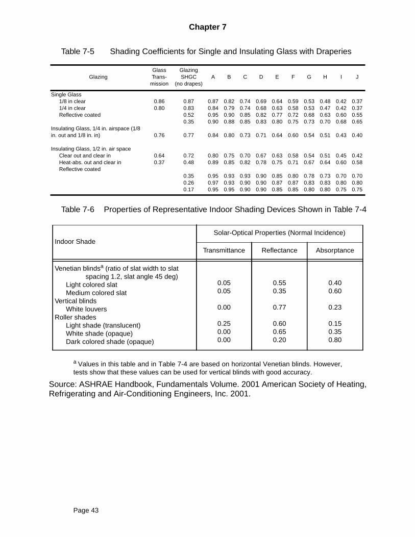
Table 7-5 Shading Coefficients for Single and Insulating Glass with Draperies
Table 7-6 Properties of Representative Indoor Shading Devices Shown in Table 7-4
a Values in this table and in Table 7-4 are based on horizontal Venetian blinds. However,tests show that these values can be used for vertical blinds with good accuracy.
Source: ASHRAE Handbook, Fundamentals Volume. 2001 American Society of Heating,Refrigerating and Air-Conditioning Engineers, Inc. 2001.
GlazingGlassTrans-
mission
GlazingSHGC
(no drapes)A B C D E F G H I J
Single Glass1/8 in clear1/4 in clearReflective coated
Insulating Glass, 1/4 in. airspace (1/8in. out and 1/8 in. in)
Insulating Glass, 1/2 in. air spaceClear out and clear inHeat-abs. out and clear inReflective coated
0.860.80
0.76
0.640.37
0.870.830.520.35
0.77
0.720.48
0.350.260.17
0.870.840.950.90
0.84
0.800.89
0.950.970.95
0.820.790.900.88
0.80
0.750.85
0.930.930.95
0.740.740.850.85
0.73
0.700.82
0.930.900.90
0.690.680.820.83
0.71
0.670.78
0.900.900.90
0.640.630.770.80
0.64
0.630.75
0.850.870.85
0.590.580.720.75
0.60
0.580.71
0.800.870.85
0.530.530.680.73
0.54
0.540.67
0.780.830.80
0.480.470.630.70
0.51
0.510.64
0.730.830.80
0.420.420.600.68
0.43
0.450.60
0.700.800.75
0.370.370.550.65
0.40
0.420.58
0.700.800.75
Indoor ShadeSolar-Optical Properties (Normal Incidence)
Transmittance Reflectance Absorptance
Venetian blindsa (ratio of slat width to slatspacing 1.2, slat angle 45 deg)
Light colored slatMedium colored slat
Vertical blindsWhite louvers
Roller shadesLight shade (translucent)White shade (opaque)Dark colored shade (opaque)
0.050.05
0.00
0.250.000.00
0.550.35
0.77
0.600.650.20
0.400.60
0.23
0.150.350.80
Page 43
Chapter 7
Figure 7-13. Indoor shading properties of drapery fabrics.
Page 44