Embed Size (px)
Citation preview
KIP Inc., Farmington, CT USA Phone 1-800-722-5547 www.kipinc.com 1
Solenoid Valves
Contents
NCA-86February 2003
How to Use This Catalog . . . . . . . . . . . . . . . . . . . . . . . . . . . 3Valve Overview
Valve Styles . . . . . . . . . . . . . . . . . . . . . . . . . . . . . . . . . . . 4-5Capabilities . . . . . . . . . . . . . . . . . . . . . . . . . . . . . . . . . . . . . 6Solenoid Selection Chart . . . . . . . . . . . . . . . . . . . . . . . . . . 7Coils Chart . . . . . . . . . . . . . . . . . . . . . . . . . . . . . . . . . . . . . 8Part Numbering System . . . . . . . . . . . . . . . . . . . . . . . . . . . 9Body Porting . . . . . . . . . . . . . . . . . . . . . . . . . . . . . . . . . . . 10Housing Styles . . . . . . . . . . . . . . . . . . . . . . . . . . . . . . . . . 11Body Material / Valve Types . . . . . . . . . . . . . . . . . . . . . . . 12Orifice / Seals . . . . . . . . . . . . . . . . . . . . . . . . . . . . . . . . . . 13Coil Construction . . . . . . . . . . . . . . . . . . . . . . . . . . . . . . . 14Rectified Coils / Diodes . . . . . . . . . . . . . . . . . . . . . . . . . . 15Manifold Mount . . . . . . . . . . . . . . . . . . . . . . . . . . . . . . . . . 16Male Bottom Port . . . . . . . . . . . . . . . . . . . . . . . . . . . . . . . 16Bottom Port - O Ring Seal . . . . . . . . . . . . . . . . . . . . . . . . 16Metering . . . . . . . . . . . . . . . . . . . . . . . . . . . . . . . . . . . . . . 173/8" Options . . . . . . . . . . . . . . . . . . . . . . . . . . . . . . . . . . . 18Valves with Brazed in Fittings or Tube Ends . . . . . . . . . . 18Filters and Screens . . . . . . . . . . . . . . . . . . . . . . . . . . . . . 18KIP Jr. Series . . . . . . . . . . . . . . . . . . . . . . . . . . . . . . . . . . 19KIP Jr. Ordering Information . . . . . . . . . . . . . . . . . . . . . . . 20KIP Isolation Valves . . . . . . . . . . . . . . . . . . . . . . . . . . . . . 21Selection Criteria for Isolation Valves . . . . . . . . . . . . . . . . 22KIP Isolation Valve PIN & Isolation Manifolds . . . . . . . . . 23Isolation Valve - Back Pressure . . . . . . . . . . . . . . . . . . . . 24R91 Water or Air Pressure Regulator . . . . . . . . . . . . . . . 25Q2 Valve . . . . . . . . . . . . . . . . . . . . . . . . . . . . . . . . . . . 26-27
ManifoldsOperator Mount . . . . . . . . . . . . . . . . . . . . . . . . . . . . . . . . 28Isolated Style . . . . . . . . . . . . . . . . . . . . . . . . . . . . . . . . . . 28Manifold Mount . . . . . . . . . . . . . . . . . . . . . . . . . . . . . . . . . 28Acrylic Subplates . . . . . . . . . . . . . . . . . . . . . . . . . . . . . . . 29OEM Design Capabilities . . . . . . . . . . . . . . . . . . . . . . . . . 29KIP Jr. . . . . . . . . . . . . . . . . . . . . . . . . . . . . . . . . . . . . . . . . 29Cartridge Fitting Inserts . . . . . . . . . . . . . . . . . . . . . . . . . . 30
Standard Manifold Ordering Information . . . . . . . . . . . . . 31Valve Ordering Information
2-Way Normally Open Valves . . . . . . . . . . . . . . . . . . . . . . 322-Way Normally Closed Valves . . . . . . . . . . . . . . . . . . . . . 333-Way Normally Closed Valves . . . . . . . . . . . . . . . . . . . . 343-Way Multi-Purpose Valves . . . . . . . . . . . . . . . . . . . . . . . 353-Way Normally Open Valves . . . . . . . . . . . . . . . . . . . . . . 363-Way Directional Control Valves . . . . . . . . . . . . . . . . . . . 37Value Added Options . . . . . . . . . . . . . . . . . . . . . . . . . . . . 38
DimensionsStandard, KIP Jr. Valve & Mounting Brackets . . . . . . . 39-40KIP Jr. Series Manifold . . . . . . . . . . . . . . . . . . . . . . . . 41-42Manifold Dimensions . . . . . . . . . . . . . . . . . . . . . . . . . . . . 43Manifold Dimensions Including Cartridge Inserts . . . . . . 44
Application ConsiderationsLiquid Flow Calculations . . . . . . . . . . . . . . . . . . . . . . . . . . 45Air/Gas Flow Calculations . . . . . . . . . . . . . . . . . . . . . . . . 46
Plastic Body Medical Valve . . . . . . . . . . . . . . . . . . . . . . . . 47Series 8 Valves
Model 8208 . . . . . . . . . . . . . . . . . . . . . . . . . . . . . . . . . 48-49Model 8241 . . . . . . . . . . . . . . . . . . . . . . . . . . . . . . . . . 50-51Model 8257 . . . . . . . . . . . . . . . . . . . . . . . . . . . . . . . . . 52-53Model 8263 . . . . . . . . . . . . . . . . . . . . . . . . . . . . . . . . . 54-55Model 8264 . . . . . . . . . . . . . . . . . . . . . . . . . . . . . . . . . 56-57Model 8265 . . . . . . . . . . . . . . . . . . . . . . . . . . . . . . . . . 58-59Model 8273 . . . . . . . . . . . . . . . . . . . . . . . . . . . . . . . . . 60-61Model 8451 . . . . . . . . . . . . . . . . . . . . . . . . . . . . . . . . . 62-63Model 8453 . . . . . . . . . . . . . . . . . . . . . . . . . . . . . . . . . 64-65Model 8501 . . . . . . . . . . . . . . . . . . . . . . . . . . . . . . . . . 66-67Model 8505 . . . . . . . . . . . . . . . . . . . . . . . . . . . . . . . . . 68-69Model 8531 . . . . . . . . . . . . . . . . . . . . . . . . . . . . . . . . . 70-71
Valve Inquiry Application Sheet . . . . . . . . . . . . . . . . . . . . 72Series 8 Valve Application Sheet . . . . . . . . . . . . . . . . . . . 73Warning / Warranty . . . . . . . . . . . . . . . . . . . . . . . . . . . . . . 74
Solenoid Valves
2 KIP Inc., Farmington, CT USA Phone 1-800-722-5547 www.kipinc.com
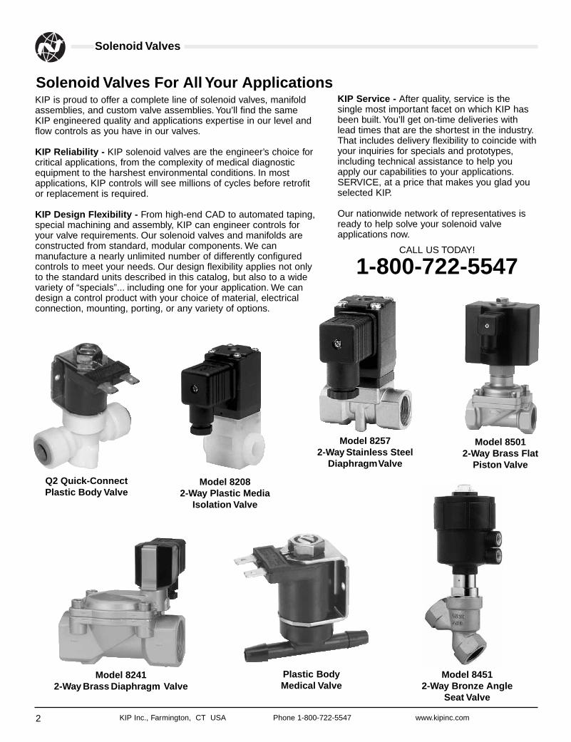
KIP is proud to offer a complete line of solenoid valves, manifoldassemblies, and custom valve assemblies. You’ll find the sameKIP engineered quality and applications expertise in our level andflow controls as you have in our valves.
KIP Reliability - KIP solenoid valves are the engineer’s choice forcritical applications, from the complexity of medical diagnosticequipment to the harshest environmental conditions. In mostapplications, KIP controls will see millions of cycles before retrofitor replacement is required.
KIP Design Flexibility - From high-end CAD to automated taping,special machining and assembly, KIP can engineer controls foryour valve requirements. Our solenoid valves and manifolds areconstructed from standard, modular components. We canmanufacture a nearly unlimited number of differently configuredcontrols to meet your needs. Our design flexibility applies not onlyto the standard units described in this catalog, but also to a widevariety of “specials”... including one for your application. We candesign a control product with your choice of material, electricalconnection, mounting, porting, or any variety of options.
Solenoid Valves For All Your Applications
Q2 Quick-ConnectPlastic Body Valve
Plastic BodyMedical Valve
KIP Service - After quality, service is thesingle most important facet on which KIP hasbeen built. You’ll get on-time deliveries withlead times that are the shortest in the industry.That includes delivery flexibility to coincide withyour inquiries for specials and prototypes,including technical assistance to help youapply our capabilities to your applications.SERVICE, at a price that makes you glad youselected KIP.
Our nationwide network of representatives isready to help solve your solenoid valveapplications now.
CALL US TODAY!
1-800-722-5547
Model 82082-Way Plastic Media
Isolation Valve
Model 82572-Way Stainless Steel
DiaphragmValve
Model 84512-Way Bronze Angle
Seat Valve
Model 85012-Way Brass Flat
Piston Valve
Model 82412-Way Brass Diaphragm Valve
Using this Catalog
3KIP Inc., Farmington, CT USA Phone 1-800-722-5547 www.kipinc.com
Solenoid Valves to Meet Your Design
Design ConsiderationsWhen the operation of your system or process requires the remotecontrol of liquid, air, gases or vacuum, the proper selection of asolenoid valve can make a significant difference in the finalperformance of the machine or process. KIP solenoid valves,operators and manifolds have the versatility and design features tofulfill all types of applications. Some consideration should be givento the following design parameters to help you with the selectionprocess:
• Valve Type• Media
- Temperature- Lubrication- Cleanliness- Isolation
• Flow Rate• Pressure• Power Consumption• Duty Cycle• Material of Construction• Electrical Termination• Porting• Mounting
Design FlexibilityThe KIP family of standard solenoid valves, solenoid valveoperators and manifolds provide a broad selection of solutions formost applications. KIP’s manufacturing and design flexibility letsyou customize the products in this catalog and tailor the product toyour exact requirements rather than tailor your requirements to astandard valve. Even if you don’t find what you need in the catalog,that doesn’t mean that we can’t do it. Many of our standardproducts started out as specialty items for our OEM customers.
CommitmentWhile the operation of solenoid valves from one company toanother is similar, KIP Incorporated distinguishes itself with totalcustomer service. From design support in the earliest phases ofyour project, to just-in-time deliveries to meet your productionschedule, KIP works with you as part of your team. So, whenmaking that critical decision, don’t just select a valve, select thevalve company that will become your partner. Select KIP!
Valve Overview
4 KIP Inc., Farmington, CT USA Phone 1-800-722-5547 www.kipinc.com
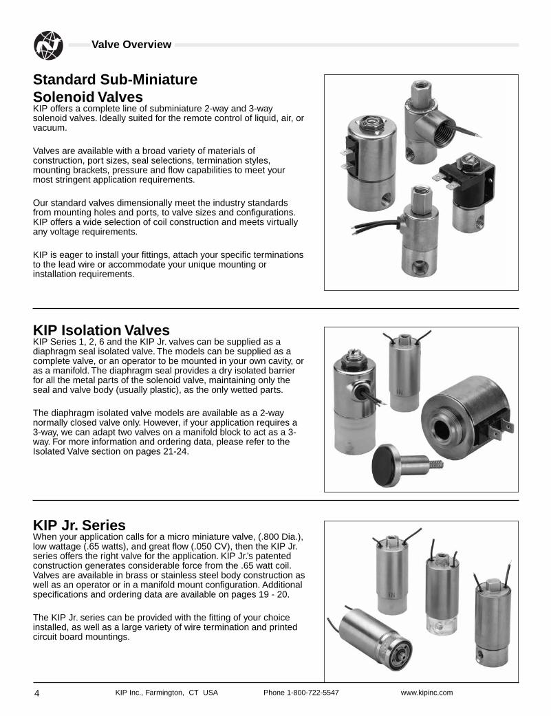
Standard Sub-Miniature Solenoid ValvesKIP offers a complete line of subminiature 2-way and 3-waysolenoid valves. Ideally suited for the remote control of liquid, air, orvacuum.
Valves are available with a broad variety of materials ofconstruction, port sizes, seal selections, termination styles,mounting brackets, pressure and flow capabilities to meet yourmost stringent application requirements.
Our standard valves dimensionally meet the industry standardsfrom mounting holes and ports, to valve sizes and configurations.KIP offers a wide selection of coil construction and meets virtuallyany voltage requirements.
KIP is eager to install your fittings, attach your specific terminationsto the lead wire or accommodate your unique mounting orinstallation requirements.
KIP Isolation ValvesKIP Series 1, 2, 6 and the KIP Jr. valves can be supplied as adiaphragm seal isolated valve. The models can be supplied as acomplete valve, or an operator to be mounted in your own cavity, oras a manifold. The diaphragm seal provides a dry isolated barrierfor all the metal parts of the solenoid valve, maintaining only theseal and valve body (usually plastic), as the only wetted parts.
The diaphragm isolated valve models are available as a 2-waynormally closed valve only. However, if your application requires a3-way, we can adapt two valves on a manifold block to act as a 3-way. For more information and ordering data, please refer to theIsolated Valve section on pages 21-24.
KIP Jr. SeriesWhen your application calls for a micro miniature valve, (.800 Dia.),low wattage (.65 watts), and great flow (.050 CV), then the KIP Jr.series offers the right valve for the application. KIP Jr.’s patentedconstruction generates considerable force from the .65 watt coil.Valves are available in brass or stainless steel body construction aswell as an operator or in a manifold mount configuration. Additionalspecifications and ordering data are available on pages 19 - 20.
The KIP Jr. series can be provided with the fitting of your choiceinstalled, as well as a large variety of wire termination and printedcircuit board mountings.
Valve Overview
5KIP Inc., Farmington, CT USA Phone 1-800-722-5547 www.kipinc.com
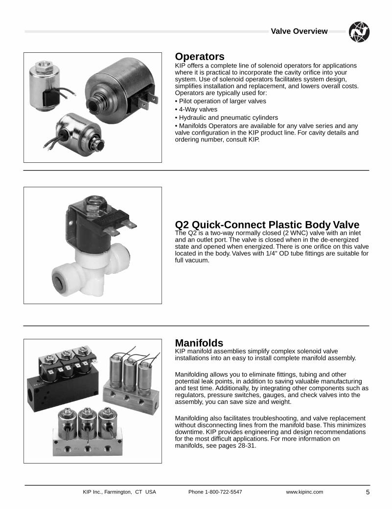
OperatorsKIP offers a complete line of solenoid operators for applicationswhere it is practical to incorporate the cavity orifice into yoursystem. Use of solenoid operators facilitates system design,simplifies installation and replacement, and lowers overall costs.Operators are typically used for:• Pilot operation of larger valves• 4-Way valves• Hydraulic and pneumatic cylinders• Manifolds Operators are available for any valve series and anyvalve configuration in the KIP product line. For cavity details andordering number, consult KIP.
Q2 Quick-Connect Plastic Body ValveThe Q2 is a two-way normally closed (2 WNC) valve with an inletand an outlet port. The valve is closed when in the de-energizedstate and opened when energized. There is one orifice on this valvelocated in the body. Valves with 1/4" OD tube fittings are suitable forfull vacuum.
ManifoldsKIP manifold assemblies simplify complex solenoid valveinstallations into an easy to install complete manifold assembly.
Manifolding allows you to eliminate fittings, tubing and otherpotential leak points, in addition to saving valuable manufacturingand test time. Additionally, by integrating other components such asregulators, pressure switches, gauges, and check valves into theassembly, you can save size and weight.
Manifolding also facilitates troubleshooting, and valve replacementwithout disconnecting lines from the manifold base. This minimizesdowntime. KIP provides engineering and design recommendationsfor the most difficult applications. For more information onmanifolds, see pages 28-31.
Capabilities
6 KIP Inc., Farmington, CT USA Phone 1-800-722-5547 www.kipinc.com
Vacuum Service KIP valves and manifolds are ideal for vacuum service and forthose special 3-way valve applications that require vacuum on oneport and pressure on another port. Valve construction is compatiblewith vacuum systems as high as 10-6 TORR. When ordering justspecify the valve number you require and note - “FOR VACUUMSERVICE”.
Oxygen Service KIP valves can be processed for oxygen service; for use in themedical industry, spectro-analysis or other applications requiringO2. These valves are specially cleaned and packaged to becontamination-free. All hydrocarbons are removed. When orderinguse the prefix “Y” in the PIN system. See page 9.
Extended Flow Capabilities KIP can increase the flow (Cv) capability of any of its valves bymodifying the mechanical and electrical components of the valve.In many cases the pressure ratings (MOPD) of the valve must bereduced to achieve the higher flow rate (Cv). When your flowrequirements exceed the catalog ratings, consult KIP forapplication engineering assistance.
Extended Pressure Ratings Solenoid valves can be modified to increase pressure ratings(MOPD) above the standard ratings listed in the catalog. If agencyapprovals are necessary, consultation with UL and/or CSA isrequired. Consult KIP with all your design parameters to determinethe feasibility of extending the pressure ratings.
Quiet Valves Solenoid valves have a distinct click that is inherent to their designwhen the two metal parts make contact. KIP offers a bumper orspecial plunger design for OEM’s that will provide a metal toelastomer contact, thus muffling the sound. In addition to providingquiet operation, this feature also extends the life of the movingparts. Quiet valves are available on 2-way and 3-way valves, DCvoltage only. Contact KIP for additional information on our quietvalve option.
Agency Approvals KIP products conform to agency approvals such as UL, cURus,CSA and NSF International. The approvals are restricted to certainproducts and specific applications. When any agency endorsementis dictated for an operation, refer to the application inquiry sheetsfor each product specified. The sheets are located in the back ofthe catalog. If additional information is needed, please contact KIP.
Low Wattage Operators, Valves and ManifoldsKIP offers the option of low wattage coils, aslow as 1.5 watts, on many of our standardvalves. These coils offer high pressure (MOPD)operation at low current levels.
• Available in both 2-Way and 3-Way models inSeries 1, Series 2, and Series 3.
• Orifice sizes from 1/32" to 5/32".• Available in 12VDC and 24VDC.• Refer to KIP solenoid valve charts for
wattage, pressure ratings and Cv factors.
KIP Series 1, 2 and 3 offer selective modelswith wattage ratings from 1.5 watts to 3 watts.After reviewing the pressure rating (MOPD) ofyour particular valve in the part number section,you may add an (A) - 1.5 watts, (B) - 2.0 watts,(C) - 2.5 watts, or a (D) - 3.0 watts as a prefix tothe part number. It is important to note thatthere is a reduced pressure rating from thestandard when a reduced wattage coil is used.
For the OEM, KIP can design and manufacturea custom coil to meet your specific flow andpressure requirements at close to standardpricing.
When 1.5 watts is not low enough, you canselect a valve from the KIP Jr. product linewhich goes as low as .65 watts while stillmaintaining significant flow and pressurespecifications.
Capabilities
Solenoid Selection Chart
7KIP Inc., Farmington, CT USA Phone 1-800-722-5547 www.kipinc.com
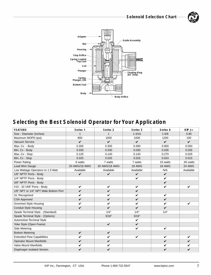
Selecting the Best Solenoid Operator for Your ApplicationFEATURE Series 1 Series 2 Series 3 Series 6 KIP Jr.Size - Diameter (inches) 1 1 1-3/16 1-5/8 0.80Maximum MOPD (psi) 800 1000 1000 1200 100Vacuum Service ✔ ✔ ✔ ✔ ✔
Max. Cv - Body 0.305 0.305 0.490 0.900 0.050Min. Cv - Body 0.030 0.030 0.030 0.035 0.035Max. Cv - Stop 0.125 0.140 0.140 0.270 0.025Min. Cv - Stop 0.025 0.025 0.025 0.024 0.015Power Rating 6 watts 7 watts 7 watts 10 watts .65 wattsLead Wire Gauge 20 AWG/18 AWG 20 AWG/18 AWG 18 AWG 18 AWG 24 AWGLow Wattage Operators to 1.5 Watt Available Available Available N/A Available1/8" NPTF Ports - Body ✔ ✔ ✔ ✔
1/4" NPTF Ports - Body ✔ ✔
3/8" NPTF Ports - Body ✔
#10 - 32 UNF Ports - Body ✔ ✔ ✔ ✔ ✔
1/8" NPT or 1/4" NPT Male Bottom Port ✔ ✔ ✔
UL Recognized ✔ ✔ ✔ ✔
CSA Approved ✔ ✔ ✔ ✔
Grommet Style Housing ✔ ✔ ✔ ✔ ✔
Conduit Style Housing ✔ ✔ ✔ ✔
Spade Terminal Style - (Standard) 1/4" 1/4" 1/4"Spade Terminal Style - (Options) 3/16" 3/16"Automotive Terminal Style ✔
Yoke Style (Open Frame) ✔ ✔
Side Metering ✔ ✔
Bottom Metering ✔ ✔
Extended Flow Capabilities ✔ ✔ ✔ ✔ ✔
Operator Mount Manifolds ✔ ✔ ✔ ✔
Valve Mount Manifolds ✔ ✔ ✔ ✔
Diaphragm Isolated Version ✔ ✔ ✔ ✔
Adapter
Nut
Housing
Stop Orifice
Spring LoadedTop Seal
Coil
Plunger
Spring,Plunger, Rtn
Bottom Seal
Body
Body Orifice
Shading Ring(AC Only)
Guide Assembly
Coils Chart
8 KIP Inc., Farmington, CT USA Phone 1-800-722-5547 www.kipinc.com
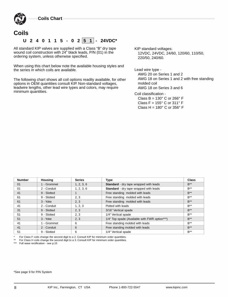
U 2 4 0 1 1 5 - 0 2 5 1 - 24VDC*
Coils
All standard KIP valves are supplied with a Class “B” dry tapewound coil construction with 24" black leads, P/N (01) in theordering system, unless otherwise specified.
When using this chart below note the available housing styles andthe series in which coils are available.
The following chart shows all coil options readily available, for otheroptions in OEM quantities consult KIP. Non-standard voltages,leadwire lengths, other lead wire types and colors, may requireminimum quantities.
* For Class F coils change the second digit to a 2. Consult KIP for minimum order quantities.** For Class H coils change the second digit to a 3. Consult KIP for minimum order quantities.*** Full wave rectification - see p.15
Number Housing Series Type Class01 1 - Grommet 1, 2, 3, 6 Standard - dry tape wrapped with leads B**01 2 - Conduit 1, 2, 3, 6 Standard - dry tape wrapped with leads B**41 9 - Slotted 1 Free standing molded with leads B**61 9 - Slotted 2, 3 Free standing molded with leads B**61 3 - Yoke 2, 3 Free standing molded with leads B**41 2 - Conduit 1, 2, 3 Potted with leads B**31 9 - Slotted 2, 3 3/16" Vertical spade B**51 9 - Slotted 2, 3 1/4" Vertical spade B**51 3 - Yoke 2, 3 1/4" Top spade (Available with FWR option***) B**41 1 - Grommet 6 Free standing molded with leads B**41 2 - Conduit 6 Free standing molded with leads B**51 9 - Slotted 6 1/4" Vertical spade B**
KIP standard voltages:12VDC, 24VDC, 24/60, 120/60, 110/50,220/50, 240/60.
Lead wire type -AWG 20 on Series 1 and 2 AWG 18 on Series 1 and 2 with free standingmolded coilAWG 18 on Series 3 and 6
Coil classification -Class B = 130° C or 266° F Class F = 155° C or 311° F Class H = 180° C or 356° F
*See page 9 for P/N System
Part Numbering System
9KIP Inc., Farmington, CT USA Phone 1-800-722-5547 www.kipinc.com
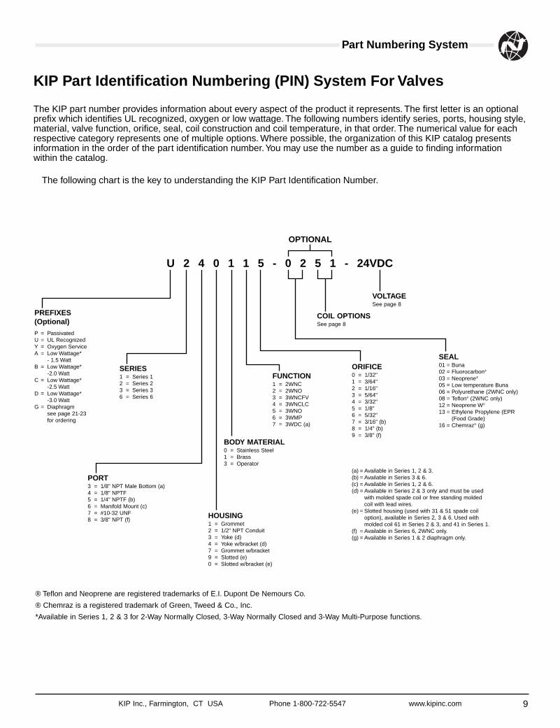
KIP Part Identification Numbering (PIN) System For Valves
The KIP part number provides information about every aspect of the product it represents. The first letter is an optionalprefix which identifies UL recognized, oxygen or low wattage. The following numbers identify series, ports, housing style,material, valve function, orifice, seal, coil construction and coil temperature, in that order. The numerical value for eachrespective category represents one of multiple options. Where possible, the organization of this KIP catalog presentsinformation in the order of the part identification number.You may use the number as a guide to finding informationwithin the catalog.
The following chart is the key to understanding the KIP Part Identification Number.
PREFIXES(Optional)P = PassivatedU = UL RecognizedY = Oxygen ServiceA = Low Wattage*
- 1.5 WattB = Low Wattage*
-2.0 WattC = Low Wattage*
-2.5 WattD = Low Wattage*
-3.0 WattG = Diaphragm
see page 21-23for ordering
SERIES1 = Series 12 = Series 23 = Series 36 = Series 6
PORT3 = 1/8" NPT Male Bottom (a)4 = 1/8" NPTF5 = 1/4" NPTF (b)6 = Manifold Mount (c)7 = #10-32 UNF8 = 3/8" NPT (f)
HOUSING1 = Grommet2 = 1/2" NPT Conduit3 = Yoke (d)4 = Yoke w/bracket (d)7 = Grommet w/bracket9 = Slotted (e)0 = Slotted w/bracket (e)
BODY MATERIAL0 = Stainless Steel1 = Brass3 = Operator
FUNCTION1 = 2WNC2 = 2WNO3 = 3WNCFV4 = 3WNCLC5 = 3WNO6 = 3WMP7 = 3WDC (a)
ORIFICE0 = 1/32"1 = 3/64"2 = 1/16"3 = 5/64"4 = 3/32"5 = 1/8"6 = 5/32"7 = 3/16" (b)8 = 1/4" (b)9 = 3/8" (f)
COIL OPTIONSSee page 8
VOLTAGESee page 8
SEAL01 = Buna02 = Fluorocarbon®
03 = Neoprene®
05 = Low temperature Buna06 = Polyurethane (2WNC only)08 = Teflon® (2WNC only)12 = Neoprene W®
13 = Ethylene Propylene (EPR(Food Grade)
16 = Chemraz® (g)
(a) = Available in Series 1, 2 & 3.(b) = Available in Series 3 & 6.(c) = Available in Series 1, 2 & 6.(d) = Available in Series 2 & 3 only and must be used
with molded spade coil or free standing moldedcoil with lead wires.
(e) = Slotted housing (used with 31 & 51 spade coiloption), available in Series 2, 3 & 6. Used withmolded coil 61 in Series 2 & 3, and 41 in Series 1.
(f) = Available in Series 6, 2WNC only.(g) = Available in Series 1 & 2 diaphragm only.
U 2 4 0 1 1 5 - 0 2 5 1 - 24VDC
OPTIONAL
® Teflon and Neoprene are registered trademarks of E.I. Dupont De Nemours Co.
® Chemraz is a registered trademark of Green, Tweed & Co., Inc.
*Available in Series 1, 2 & 3 for 2-Way Normally Closed, 3-Way Normally Closed and 3-Way Multi-Purpose functions.
Body Porting
10 KIP Inc., Farmington, CT USA Phone 1-800-722-5547 www.kipinc.com
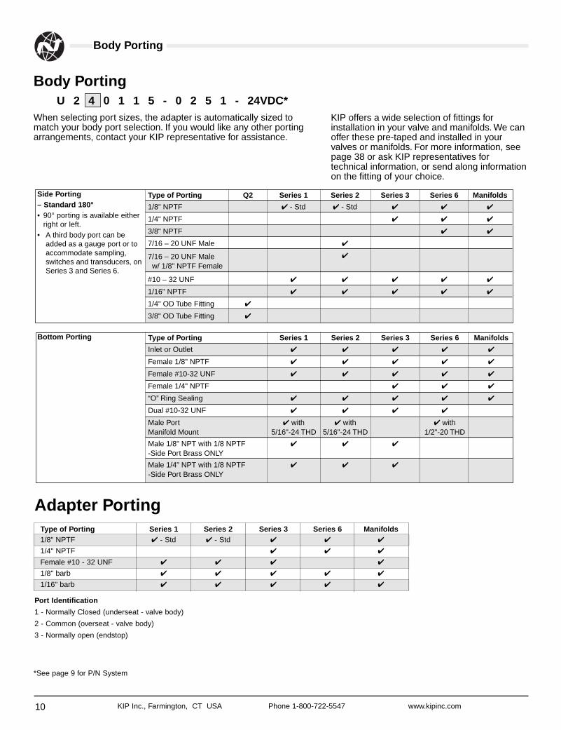
U 2 4 0 1 1 5 - 0 2 5 1 - 24VDC*
Body Porting
When selecting port sizes, the adapter is automatically sized tomatch your body port selection. If you would like any other portingarrangements, contact your KIP representative for assistance.
Side Porting– Standard 180°• 90° porting is available either
right or left.• A third body port can be
added as a gauge port or toaccommodate sampling,switches and transducers, onSeries 3 and Series 6.
Type of Porting Series 1 Series 2 Series 3 Series 6 Manifolds1/8" NPTF ✔ - Std ✔ - Std ✔ ✔ ✔
1/4" NPTF ✔ ✔ ✔
Female #10 - 32 UNF ✔ ✔ ✔ ✔
1/8" barb ✔ ✔ ✔ ✔ ✔
1/16" barb ✔ ✔ ✔ ✔ ✔
Adapter Porting
*See page 9 for P/N System
KIP offers a wide selection of fittings forinstallation in your valve and manifolds. We canoffer these pre-taped and installed in yourvalves or manifolds. For more information, seepage 38 or ask KIP representatives fortechnical information, or send along informationon the fitting of your choice.
Type of Porting Q2 Series 1 Series 2 Series 3 Series 6 Manifolds
1/8" NPTF ✔ - Std ✔ - Std ✔ ✔ ✔
1/4" NPTF ✔ ✔ ✔
3/8" NPTF ✔ ✔
7/16 – 20 UNF Male ✔
7/16 – 20 UNF Male ✔
w/ 1/8" NPTF Female
#10 – 32 UNF ✔ ✔ ✔ ✔ ✔
1/16" NPTF ✔ ✔ ✔ ✔ ✔
1/4" OD Tube Fitting ✔
3/8" OD Tube Fitting ✔
Bottom Porting Type of Porting Series 1 Series 2 Series 3 Series 6 Manifolds
Inlet or Outlet ✔ ✔ ✔ ✔ ✔
Female 1/8" NPTF ✔ ✔ ✔ ✔ ✔
Female #10-32 UNF ✔ ✔ ✔ ✔ ✔
Female 1/4" NPTF ✔ ✔ ✔
“O” Ring Sealing ✔ ✔ ✔ ✔ ✔
Dual #10-32 UNF ✔ ✔ ✔ ✔
Male Port ✔ with ✔ with ✔ withManifold Mount 5/16"-24 THD 5/16"-24 THD 1/2"-20 THD
Male 1/8" NPT with 1/8 NPTF ✔ ✔ ✔
-Side Port Brass ONLY
Male 1/4" NPT with 1/8 NPTF ✔ ✔ ✔
-Side Port Brass ONLY
Port Identification
1 - Normally Closed (underseat - valve body)
2 - Common (overseat - valve body)
3 - Normally open (endstop)
Housing Styles
11KIP Inc., Farmington, CT USA Phone 1-800-722-5547 www.kipinc.com
U 2 4 0 1 1 5 - 0 2 5 1 - 24VDC*
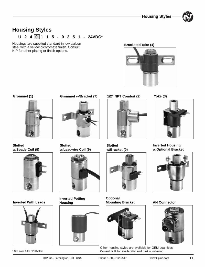
Housing Styles
Housings are supplied standard in low carbonsteel with a yellow dichromate finish. ConsultKIP for other plating or finish options.
Grommet (1) Grommet w/Bracket (7) 1/2" NPT Conduit (2) Yoke (3)
Bracketed Yoke (4)
Slottedw/Spade Coil (9)
Slottedw/Leadwire Coil (9)
Slottedw/Bracket (0)
Inverted Housingw/Optional Bracket
Inverted With LeadsInverted PottingHousing
OptionalMounting Bracket AN Connector
Other housing styles are available for OEM quantities.Consult KIP for availability and part numbering.* See page 9 for P/N System
12 KIP Inc., Farmington, CT USA Phone 1-800-722-5547 www.kipinc.com
Body Material / Valve Types
U 2 4 0 1 1 5 - 0 2 5 1 - 24VDC*
Body Material
KIP offers valve bodies in three standard materials. Brass, 430FStainless Steel, and injection molded Polypropylene. KIP alsooffers bodies manufactured in 303 Stainless Steel, Aluminum,
U 2 4 0 1 1 5 - 0 2 5 1 - 24VDC*
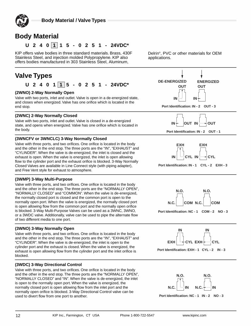
Valve Types
(2WNO) 2-Way Normally OpenValve with two ports, inlet and outlet. Valve is open in a de-energized state,and closes when energized. Valve has one orifice which is located in theend stop.
(2WNC) 2-Way Normally ClosedValve with two ports, inlet and outlet. Valve is closed in a de-energizedstate, and opens when energized. Valve has one orifice which is located inthe body.
(3WNCFV or 3WNCLC) 3-Way Normally ClosedValve with three ports, and two orifices. One orifice is located in the bodyand the other in the end stop. The three ports are the “IN”, “EXHAUST” and“CYLINDER”. When the valve is de-energized, the inlet is closed and theexhaust is open. When the valve is energized, the inlet is open allowingflow to the cylinder port and the exhaust orifice is blocked. 3-Way NormallyClosed Valves are available in Line Connect style (with piping adapter),and Free Vent style for exhaust to atmosphere.
(3WMP) 3-Way Multi-PurposeValve with three ports, and two orifices. One orifice is located in the bodyand the other in the end stop. The three ports are the “NORMALLY OPEN”,“NORMALLY CLOSED” and “COMMON”. When the valve is de-energized,the normally closed port is closed and the common port is open to thenormally open port. When the valve is energized, the normally closed portis open allowing flow from the common port and the normally open orificeis blocked. 3-Way Multi-Purpose Valves can be used as a 3WNC, 3WNO,or a 3WDC valve. Additionally, valve can be used to pipe the alternate flowof two different media to one port.
(3WNO) 3-Way Normally OpenValve with three ports, and two orifices. One orifice is located in the bodyand the other in the end stop. The three ports are the “IN”, “EXHAUST” and“CYLINDER”. When the valve is de-energized, the inlet is open to thecylinder port and the exhaust is closed. When the valve is energized, theexhaust is open allowing flow from the cylinder port and the inlet orifice isblocked.
(3WDC) 3-Way Directional ControlValve with three ports, and two orifices. One orifice is located in the bodyand the other in the end stop. The three ports are the “NORMALLY OPEN”,“NORMALLY CLOSED” and “IN”. When the valve is de-energized, the inletis open to the normally open port. When the valve is energized, thenormally closed port is open allowing flow from the inlet port and thenormally open orifice is blocked. 3-Way Directional Control valve can beused to divert flow from one port to another.
Delrin®, PVC or other materials for OEMapplications.
OUT
IN IN
DE-ENERGIZED ENERGIZEDOUT
Port Identification: IN - 2 OUT - 3
OUTINOUTIN
Port Identification: IN - 2 OUT - 1
EXH
IN CYL
EXH
IN CYL
Port Identification: IN - 1 CYL - 2 EXH - 3
N.O.
N.C. COM
N.O.
N.C. COM
Port Identification: NC - 1 COM - 2 NO - 3
IN
EXH CYL
IN
EXH CYL
Port Identification: EXH - 1 CYL - 2 IN - 3
N.O.
N.C. IN
N.O.
N.C. IN
Port Identification: NC - 1 IN - 2 NO - 3
Orifice/Seals
13KIP Inc., Farmington, CT USA Phone 1-800-722-5547 www.kipinc.com
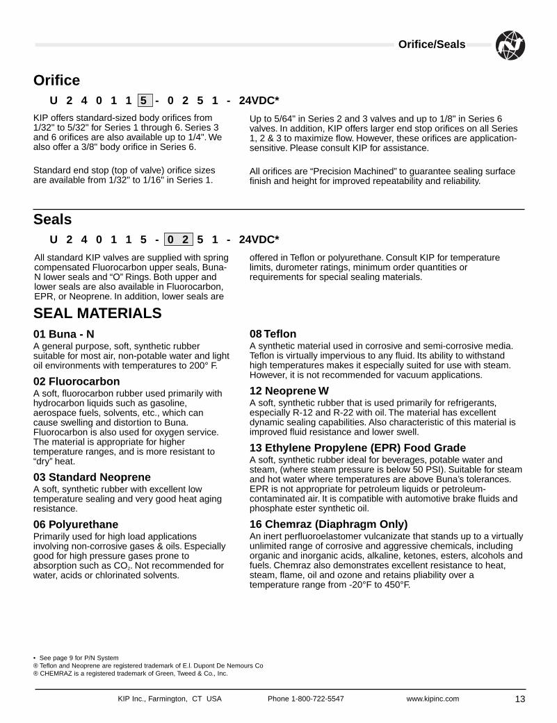
Orifice
KIP offers standard-sized body orifices from1/32" to 5/32" for Series 1 through 6. Series 3and 6 orifices are also available up to 1/4". Wealso offer a 3/8" body orifice in Series 6.
Standard end stop (top of valve) orifice sizesare available from 1/32" to 1/16" in Series 1.
Seals
SEAL MATERIALS01 Buna - N A general purpose, soft, synthetic rubbersuitable for most air, non-potable water and lightoil environments with temperatures to 200° F.
02 Fluorocarbon A soft, fluorocarbon rubber used primarily withhydrocarbon liquids such as gasoline,aerospace fuels, solvents, etc., which cancause swelling and distortion to Buna.Fluorocarbon is also used for oxygen service.The material is appropriate for highertemperature ranges, and is more resistant to“dry” heat.
03 Standard Neoprene A soft, synthetic rubber with excellent lowtemperature sealing and very good heat agingresistance.
06 Polyurethane Primarily used for high load applicationsinvolving non-corrosive gases & oils. Especiallygood for high pressure gases prone toabsorption such as CO2. Not recommended forwater, acids or chlorinated solvents.
• See page 9 for P/N System® Teflon and Neoprene are registered trademark of E.l. Dupont De Nemours Co® CHEMRAZ is a registered trademark of Green, Tweed & Co., Inc.
Up to 5/64" in Series 2 and 3 valves and up to 1/8" in Series 6valves. In addition, KIP offers larger end stop orifices on all Series1, 2 & 3 to maximize flow. However, these orifices are application-sensitive. Please consult KIP for assistance.
All orifices are “Precision Machined” to guarantee sealing surfacefinish and height for improved repeatability and reliability.
08 Teflon A synthetic material used in corrosive and semi-corrosive media.Teflon is virtually impervious to any fluid. Its ability to withstandhigh temperatures makes it especially suited for use with steam.However, it is not recommended for vacuum applications.
12 Neoprene W A soft, synthetic rubber that is used primarily for refrigerants,especially R-12 and R-22 with oil. The material has excellentdynamic sealing capabilities. Also characteristic of this material isimproved fluid resistance and lower swell.
13 Ethylene Propylene (EPR) Food Grade A soft, synthetic rubber ideal for beverages, potable water andsteam, (where steam pressure is below 50 PSI). Suitable for steamand hot water where temperatures are above Buna’s tolerances.EPR is not appropriate for petroleum liquids or petroleum-contaminated air. It is compatible with automotive brake fluids andphosphate ester synthetic oil.
16 Chemraz (Diaphragm Only) An inert perfluoroelastomer vulcanizate that stands up to a virtuallyunlimited range of corrosive and aggressive chemicals, includingorganic and inorganic acids, alkaline, ketones, esters, alcohols andfuels. Chemraz also demonstrates excellent resistance to heat,steam, flame, oil and ozone and retains pliability over atemperature range from -20°F to 450°F.
All standard KIP valves are supplied with springcompensated Fluorocarbon upper seals, Buna-N lower seals and “O” Rings. Both upper andlower seals are also available in Fluorocarbon,EPR, or Neoprene. In addition, lower seals are
offered in Teflon or polyurethane. Consult KIP for temperaturelimits, durometer ratings, minimum order quantities orrequirements for special sealing materials.
U 2 4 0 1 1 5 - 0 2 5 1 - 24VDC*
U 2 4 0 1 1 5 - 0 2 5 1 - 24VDC*
Coil Construction
14 KIP Inc., Farmington, CT USA Phone 1-800-722-5547 www.kipinc.com
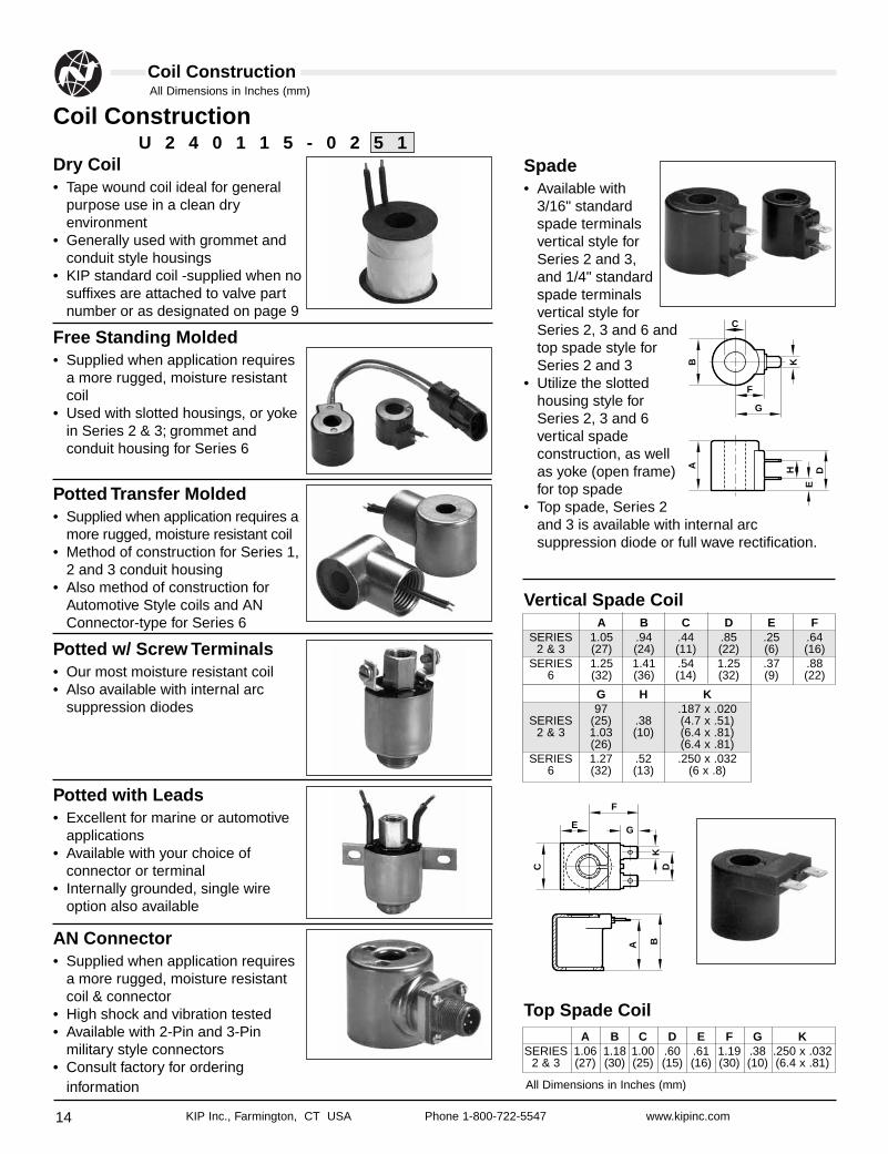
Spade• Available with
3/16" standardspade terminalsvertical style forSeries 2 and 3,and 1/4" standardspade terminalsvertical style forSeries 2, 3 and 6 andtop spade style forSeries 2 and 3
• Utilize the slottedhousing style forSeries 2, 3 and 6vertical spadeconstruction, as wellas yoke (open frame)for top spade
• Top spade, Series 2and 3 is available with internal arcsuppression diode or full wave rectification.
Vertical Spade Coil
Top Spade Coil
Dry Coil• Tape wound coil ideal for general
purpose use in a clean dryenvironment
• Generally used with grommet andconduit style housings
• KIP standard coil -supplied when nosuffixes are attached to valve partnumber or as designated on page 9
Free Standing Molded• Supplied when application requires
a more rugged, moisture resistantcoil
• Used with slotted housings, or yokein Series 2 & 3; grommet andconduit housing for Series 6
Potted Transfer Molded• Supplied when application requires a
more rugged, moisture resistant coil• Method of construction for Series 1,
2 and 3 conduit housing• Also method of construction for
Automotive Style coils and ANConnector-type for Series 6
Potted w/ Screw Terminals• Our most moisture resistant coil• Also available with internal arc
suppression diodes
Potted with Leads• Excellent for marine or automotive
applications• Available with your choice of
connector or terminal• Internally grounded, single wire
option also available
AN Connector• Supplied when application requires
a more rugged, moisture resistantcoil & connector
• High shock and vibration tested• Available with 2-Pin and 3-Pin
military style connectors• Consult factory for ordering
information
Coil Construction
B K
E
A DH
C
G
F
C D
A B
F
GE
K
A B C D E FSERIES 1.05 .94 .44 .85 .25 .64
2 & 3 (27) (24) (11) (22) (6) (16)SERIES 1.25 1.41 .54 1.25 .37 .88
6 (32) (36) (14) (32) (9) (22)
G H K97 .187 x .020
SERIES (25) .38 (4.7 x .51)2 & 3 1.03 (10) (6.4 x .81)
(26) (6.4 x .81)SERIES 1.27 .52 .250 x .032
6 (32) (13) (6 x .8)
A B C D E F G KSERIES 1.06 1.18 1.00 .60 .61 1.19 .38 .250 x .032
2 & 3 (27) (30) (25) (15) (16) (30) (10) (6.4 x .81)
U 2 4 0 1 1 5 - 0 2 5 1
All Dimensions in Inches (mm)
All Dimensions in Inches (mm)
Rectified Coils/Diodes
15KIP Inc., Farmington, CT USA Phone 1-800-722-5547 www.kipinc.com
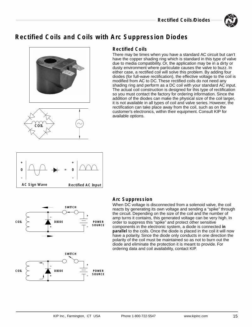
Rectified CoilsThere may be times when you have a standard AC circuit but can’thave the copper shading ring which is standard in this type of valvedue to media compatibility. Or, the application may be in a dirty ordusty environment where particulate causes the valve to buzz. Ineither case, a rectified coil will solve this problem. By adding fourdiodes (for full-wave rectification), the effective voltage to the coil ismodified from AC to DC. These rectified coils do not need anyshading ring and perform as a DC coil with your standard AC input.The actual coil construction is designed for this type of rectificationso you must contact the factory for ordering information. Since theaddition of the diodes can make the physical size of the coil larger,it is not available in all types of coil and valve series. However, therectification can take place away from the coil, such as on thecustomer’s electronics, within their equipment. Consult KIP foravailable options.
Arc SuppressionWhen DC voltage is disconnected from a solenoid valve, the coilreacts by generating its own voltage and sending a “spike” throughthe circuit. Depending on the size of the coil and the number ofamp turns it contains, this generated voltage can be very high. Inorder to suppress this “spike” and protect other sensitivecomponents in the electronic system, a diode is connected inparallel to the coils. Once the diode is placed in the coil it will nowhave a polarity. Since the diode only conducts in one direction thepolarity of the coil must be maintained so as not to burn out thediode and eliminate the protection it is meant to provide. Forordering data and coil availability, contact KIP.
Rectified Coils and Coils with Arc Suppression Diodes
COIL DIODE
SWITCH
POWERSOURCE
–
+ –
+
COIL DIODE
SWITCH
POWERSOURCE
–
+ –
+
COIL
+
0
-
+
0
-
=
AC Sign Wave Rectified AC Input
Porting
16 KIP Inc., Farmington, CT USA Phone 1-800-722-5547 www.kipinc.com
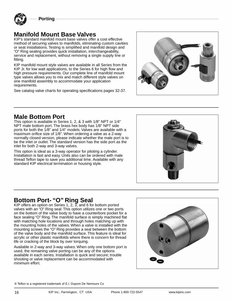
Manifold Mount Base ValvesKIP’s standard manifold mount base valves offer a cost effectivemethod of securing valves to manifolds, eliminating custom cavitiesor seat installations. Testing is simplified and manifold design and“O” Ring sealing provides quick installation, interchangeability,service and replacement, without removing a single supply line orfitting.KIP manifold mount style valves are available in all Series from theKIP Jr. for low watt applications, to the Series 6 for high flow andhigh pressure requirements. Our complete line of manifold mounttype valves allows you to mix and match different style valves onone manifold assembly to accommodate your applicationrequirements.See catalog valve charts for operating specifications pages 32-37.
Male Bottom PortThis option is available in Series 1, 2, & 3 with 1/8" NPT or 1/4"NPT male bottom port. The brass hex body has 1/8" NPT sideports for both the 1/8" and 1/4" models. Valves are available with amaximum orifice size of 1/8". When ordering a valve as a 2-waynormally closed version, please indicate whether the male port is tobe the inlet or outlet. The standard version has the side port as theinlet for both 2-way and 3-way valves.This option is ideal as a 3-way operator for piloting a cylinder.Installation is fast and easy. Units also can be ordered with malethread Teflon tape to save you additional time. Available with anystandard KIP electrical termination or housing style.
Bottom Port- “O” Ring SealKIP offers an option on Series 1, 2, 3, and 6 for bottom portedvalves with an “O” Ring seal. This option utilizes one or two portson the bottom of the valve body to have a counterbore pocket for aface sealing “O” Ring. The manifold surface is simply machined flatwith matching hole locations and through holes matching up withthe mounting holes of the valves. When a valve is installed with themounting screws the “O” Ring provides a seal between the bottomof the valve body and the manifold surface. This feature is ideal foracrylic or other plastic manifolds where there is concern for threadlife or cracking of the block by over torquing.Available in 2-way and 3-way valves. When only one bottom port isused, the remaining valve porting can be any of the optionsavailable in each series. Installation is quick and secure; troubleshooting or valve replacement can be accommodated withminimum effort.
® Teflon is a registered trademark of E.I. Dupont De Nemours Co
17KIP Inc., Farmington, CT USA Phone 1-800-722-5547 www.kipinc.com
Metering
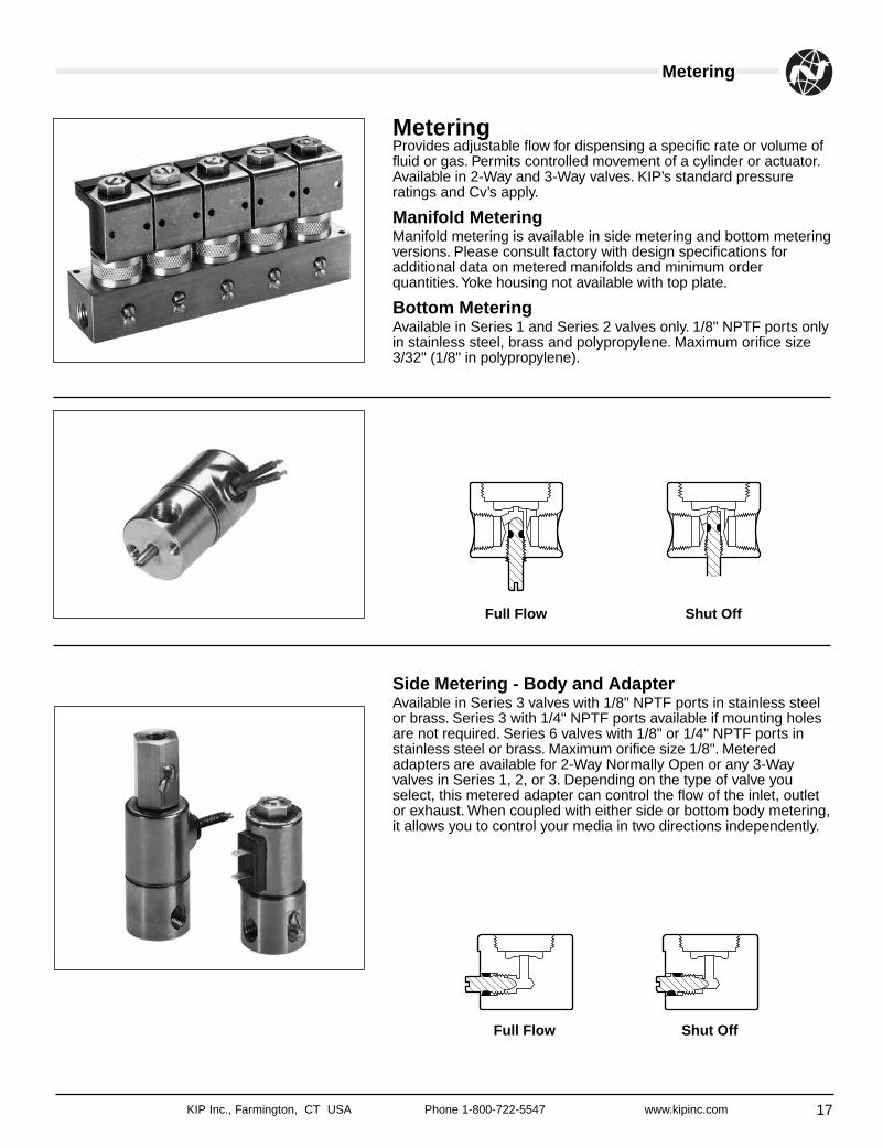
MeteringProvides adjustable flow for dispensing a specific rate or volume offluid or gas. Permits controlled movement of a cylinder or actuator.Available in 2-Way and 3-Way valves. KIP’s standard pressureratings and Cv’s apply.
Manifold Metering Manifold metering is available in side metering and bottom meteringversions. Please consult factory with design specifications foradditional data on metered manifolds and minimum orderquantities.Yoke housing not available with top plate.
Bottom Metering Available in Series 1 and Series 2 valves only. 1/8" NPTF ports onlyin stainless steel, brass and polypropylene. Maximum orifice size3/32" (1/8" in polypropylene).
Side Metering - Body and Adapter Available in Series 3 valves with 1/8" NPTF ports in stainless steelor brass. Series 3 with 1/4" NPTF ports available if mounting holesare not required. Series 6 valves with 1/8" or 1/4" NPTF ports instainless steel or brass. Maximum orifice size 1/8". Meteredadapters are available for 2-Way Normally Open or any 3-Wayvalves in Series 1, 2, or 3. Depending on the type of valve youselect, this metered adapter can control the flow of the inlet, outletor exhaust. When coupled with either side or bottom body metering,it allows you to control your media in two directions independently.
Full Flow Shut Off
Full Flow Shut Off
Fittings and Filters
18 KIP Inc., Farmington, CT USA Phone 1-800-722-5547 www.kipinc.com
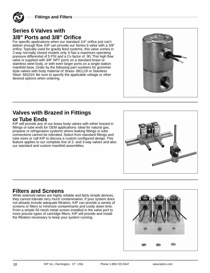
Series 6 Valves with 3/8" Ports and 3/8" OrificeFor specific applications when our standard 1/4" orifice just can’tdeliver enough flow, KIP can provide our Series 6 valve with a 3/8"orifice. Typically used for gravity feed systems, this valve comes in2-way normally closed models only. It has a maximum operatingpressure differential of 5 PSI and a Cv factor of .90. This high flowvalve is supplied with 3/8" NPT ports on a standard brass orstainless steel body, or with even larger ports on a single stationmanifold base. Order by the following part numbers for grommetstyle valves with body material of: Brass- 681119 or StainlessSteel- 681019. Be sure to specify the applicable voltage or otherdesired options when ordering.
Valves with Brazed in Fittings or Tube EndsKIP will provide any of our brass body valves with either brazed infittings or tube ends for OEM applications. Ideal for natural gas,propane or refrigeration systems where leaking fittings or tubeconnections cannot be tolerated. Select from standard fittings andtube sizes or call KIP to discuss a custom configured design. Thisfeature applies to our complete line of 2- and 3-way valves and alsoour standard and custom manifold assemblies.
Filters and ScreensWhile solenoid valves are highly reliable and fairly simple devices,they cannot tolerate very much contamination. If your system doesnot already include adequate filtration, KIP can provide a variety ofscreens or filters to minimize contaminants and costly down time.From a simple 50 mesh metal screen installed in the valve port tomore precise types of cartridge filters, KIP will provide and installthe filtration necessary to keep your system running.
KIP Jr. Series
19KIP Inc., Farmington, CT USA Phone 1-800-722-5547 www.kipinc.com
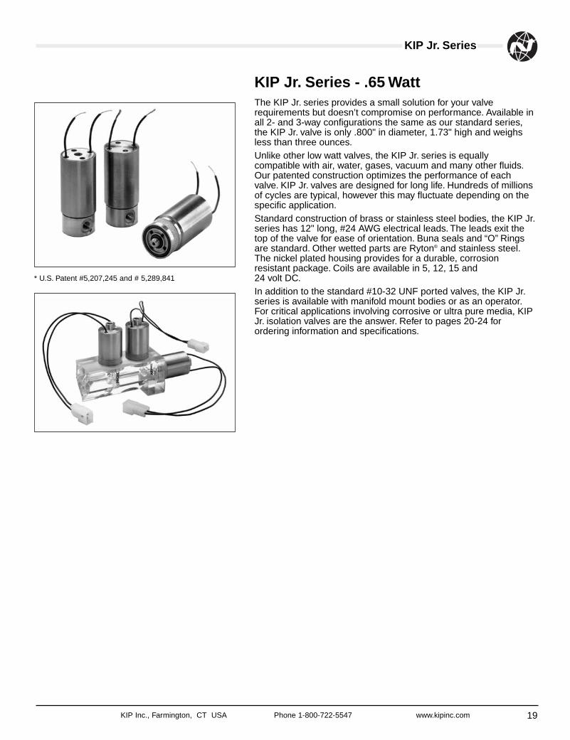
KIP Jr. Series - .65 WattThe KIP Jr. series provides a small solution for your valverequirements but doesn’t compromise on performance. Available inall 2- and 3-way configurations the same as our standard series,the KIP Jr. valve is only .800" in diameter, 1.73" high and weighsless than three ounces.Unlike other low watt valves, the KIP Jr. series is equallycompatible with air, water, gases, vacuum and many other fluids.Our patented construction optimizes the performance of eachvalve. KIP Jr. valves are designed for long life. Hundreds of millionsof cycles are typical, however this may fluctuate depending on thespecific application.Standard construction of brass or stainless steel bodies, the KIP Jr.series has 12" long, #24 AWG electrical leads. The leads exit thetop of the valve for ease of orientation. Buna seals and “O” Ringsare standard. Other wetted parts are Ryton® and stainless steel.The nickel plated housing provides for a durable, corrosionresistant package. Coils are available in 5, 12, 15 and 24 volt DC.In addition to the standard #10-32 UNF ported valves, the KIP Jr.series is available with manifold mount bodies or as an operator.For critical applications involving corrosive or ultra pure media, KIPJr. isolation valves are the answer. Refer to pages 20-24 forordering information and specifications.
* U.S. Patent #5,207,245 and # 5,289,841
KIP Jr. Ordering
20 KIP Inc., Farmington, CT USA Phone 1-800-722-5547 www.kipinc.com
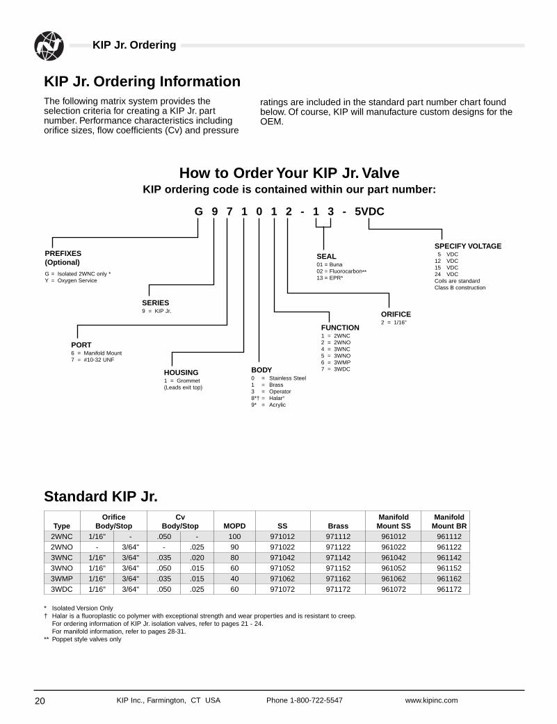
The following matrix system provides theselection criteria for creating a KIP Jr. partnumber. Performance characteristics includingorifice sizes, flow coefficients (Cv) and pressure
KIP Jr. Ordering Information
How to Order Your KIP Jr. ValveKIP ordering code is contained within our part number:
Standard KIP Jr.
* Isolated Version Only† Halar is a fluoroplastic co polymer with exceptional strength and wear properties and is resistant to creep.
For ordering information of KIP Jr. isolation valves, refer to pages 21 - 24.For manifold information, refer to pages 28-31.
** Poppet style valves only
PREFIXES(Optional)G = Isolated 2WNC only *Y = Oxygen Service
SERIES9 = KIP Jr.
PORT6 = Manifold Mount7 = #10-32 UNF
HOUSING1 = Grommet(Leads exit top)
BODY0 = Stainless Steel1 = Brass3 = Operator8*† = Halar®
9* = Acrylic
FUNCTION1 = 2WNC2 = 2WNO4 = 3WNC5 = 3WNO6 = 3WMP7 = 3WDC
ORIFICE2 = 1/16"
SPECIFY VOLTAGE5 VDC
12 VDC15 VDC24 VDCCoils are standardClass B construction
SEAL01 = Buna02 = Fluorocarbon**13 = EPR*
G 9 7 1 0 1 2 - 1 3 - 5VDC
Orifice Cv Manifold ManifoldType Body/Stop Body/Stop MOPD SS Brass Mount SS Mount BR
2WNC 1/16" - .050 - 100 971012 971112 961012 9611122WNO - 3/64" - .025 90 971022 971122 961022 9611223WNC 1/16" 3/64" .035 .020 80 971042 971142 961042 9611423WNO 1/16" 3/64" .050 .015 60 971052 971152 961052 9611523WMP 1/16" 3/64" .035 .015 40 971062 971162 961062 9611623WDC 1/16" 3/64" .050 .025 60 971072 971172 961072 961172
ratings are included in the standard part number chart foundbelow. Of course, KIP will manufacture custom designs for theOEM.
KIP Inc., Farmington, CT USA Phone 1-800-722-5547 www.kipinc.com
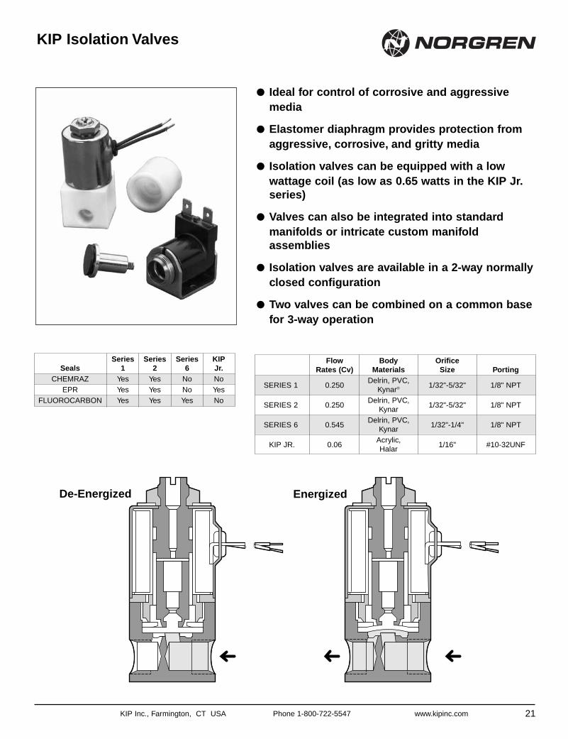
● Ideal for control of corrosive and aggressivemedia
● Elastomer diaphragm provides protection fromaggressive, corrosive, and gritty media
● Isolation valves can be equipped with a lowwattage coil (as low as 0.65 watts in the KIP Jr.series)
● Valves can also be integrated into standardmanifolds or intricate custom manifoldassemblies
● Isolation valves are available in a 2-way normallyclosed configuration
● Two valves can be combined on a common basefor 3-way operation
KIP Isolation Valves
21
Flow Body OrificeRates (Cv) Materials Size Porting
SERIES 1 0.250Delrin, PVC,
1/32"-5/32" 1/8" NPTKynar®
SERIES 2 0.250Delrin, PVC,
1/32"-5/32" 1/8" NPTKynar
SERIES 6 0.545Delrin, PVC,
1/32"-1/4" 1/8" NPTKynar
KIP JR. 0.06Acrylic,
1/16" #10-32UNFHalar
Series Series Series KIP Seals 1 2 6 Jr.
CHEMRAZ Yes Yes No NoEPR Yes Yes No Yes
FLUOROCARBON Yes Yes Yes No
De-Energized Energized
Isolation Valves
22 KIP Inc., Farmington, CT USA Phone 1-800-722-5547 www.kipinc.com
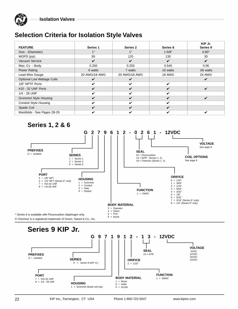
Selection Criteria for Isolation Style ValvesKIP Jr.
FEATURE Series 1 Series 2 Series 6 Series 9Size - (Diameter) 1" 1" 1-5/8" 0.80"MOPD (psi) 95 120 130 30Vacuum Service ✔ ✔ ✔ ✔
Max. Cv - Body 0.250 0.250 0.545 0.06Power Rating 6 watts 7 watts 10 watts .65 wattsLead Wire Gauge 20 AWG/18 AWG 20 AWG/18 AWG 18 AWG 24 AWGOptional Low Wattage Coils ✔ ✔ ✔
1/8" NPTF Ports ✔ ✔ ✔
#10 - 32 UNF Ports ✔ ✔ ✔ ✔
1/4 - 28 UNF ✔ ✔ ✔
Grommet Style Housing ✔ ✔ ✔ ✔
Conduit Style Housing ✔ ✔ ✔
Spade Coil ✔ ✔ ✔
Manifolds - See Pages 28-29 ✔ ✔ ✔ ✔
PREFIXESG = Isolated SERIES
1 = Series 12 = Series 26 = Series 6
PORT4 = 1/8" NPT5 = 1/4" NPT (Series 6* only)7 = #10-32 UNF8 = 1/4-28 UNF
HOUSING1 = Grommet2 = Conduit3 = Yoke9 = Slotted
BODY MATERIAL3 = Operator4 = Delrin5 = PVC6 = Kynar
FUNCTION1 = 2WNC
ORIFICE0 = 1/32"1 = 3/64"2 = 1/16"3 = 5/64"4 = 3/32"5 = 1/8"6 = 5/32"7 = 3/16" (Series 6* only)8 = 1/4" (Series 6* only)
VOLTAGESee page 8
SEAL02 = Fluorocarbon13 = EPR* (Series 1, 2)16 = Chemraz (Series 1, 2)
COIL OPTIONSSee page 8
G 2 7 9 6 1 2 - 0 2 6 1 - 12VDCSeries 1, 2 & 6
PREFIXESG = Isolated SERIES
9 = Series 9 (KIP Jr.)
PORT7 = #10-32 UNF8 = 1/4 - 28 UNF HOUSING
1 = Grommet (leads exit top)
BODY MATERIAL1 = Brass8 = Halar9 = Acrylic
FUNCTION1 = 2WNC
ORIFICE2 = 1/16"
VOLTAGE5VDC
12VDC15VDC24VDC
SEAL13 = EPR
G 9 7 1 9 1 2 - 1 3 - 12VDCSeries 9 KIP Jr.
* Series 6 is available with Fluorocarbon diaphragm only.
® Chemraz is a registered trademark of Green, Tweed & Co., Inc.
KIP Inc., Farmington, CT USA Phone 1-800-722-5547 www.kipinc.com
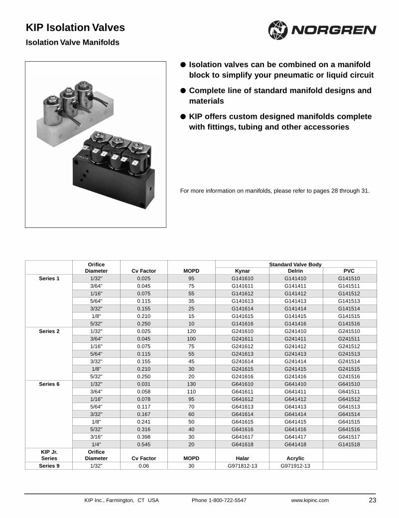
● Isolation valves can be combined on a manifoldblock to simplify your pneumatic or liquid circuit
● Complete line of standard manifold designs andmaterials
● KIP offers custom designed manifolds completewith fittings, tubing and other accessories
For more information on manifolds, please refer to pages 28 through 31.
KIP Isolation ValvesIsolation Valve Manifolds
23
Orifice Standard Valve BodyDiameter Cv Factor MOPD Kynar Delrin PVC
Series 1 1/32" 0.025 95 G141610 G141410 G1415103/64" 0.045 75 G141611 G141411 G1415111/16" 0.075 55 G141612 G141412 G1415125/64" 0.115 35 G141613 G141413 G1415133/32" 0.155 25 G141614 G141414 G1415141/8" 0.210 15 G141615 G141415 G1415155/32" 0.250 10 G141616 G141416 G141516
Series 2 1/32" 0.025 120 G241610 G241410 G2415103/64" 0.045 100 G241611 G241411 G2415111/16" 0.075 75 G241612 G241412 G2415125/64" 0.115 55 G241613 G241413 G2415133/32" 0.155 45 G241614 G241414 G2415141/8" 0.210 30 G241615 G241415 G2415155/32" 0.250 20 G241616 G241416 G241516
Series 6 1/32" 0.031 130 G641610 G641410 G6415103/64" 0.058 110 G641611 G641411 G6415111/16" 0.078 95 G641612 G641412 G6415125/64" 0.117 70 G641613 G641413 G6415133/32" 0.167 60 G641614 G641414 G6415141/8" 0.241 50 G641615 G641415 G6415155/32" 0.316 40 G641616 G641416 G6415163/16" 0.398 30 G641617 G641417 G6415171/4" 0.545 20 G641618 G641418 G141518
KIP Jr. OrificeSeries Diameter Cv Factor MOPD Halar Acrylic
Series 9 1/32" 0.06 30 G971812-13 G971912-13
Back Pressure
24 KIP Inc., Farmington, CT USA Phone 1-800-722-5547 www.kipinc.com
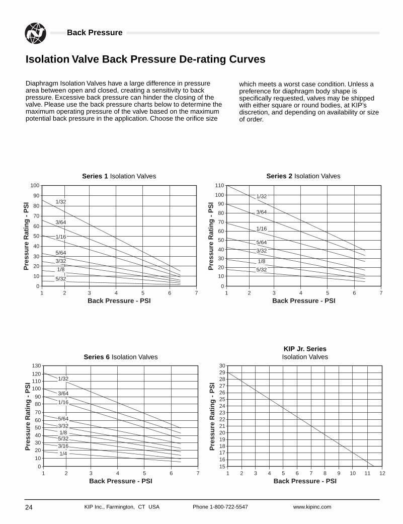
Diaphragm Isolation Valves have a large difference in pressurearea between open and closed, creating a sensitivity to backpressure. Excessive back pressure can hinder the closing of thevalve. Please use the back pressure charts below to determine themaximum operating pressure of the valve based on the maximumpotential back pressure in the application. Choose the orifice size
Isolation Valve Back Pressure De-rating Curves
1
100
2 3 4 5 6 7
90
80
70
60
50
40
30
20
10
0
Back Pressure - PSI
Pre
ssu
re R
atin
g -
PS
I
1
110
2 3 4 5 6 7
120
130
100
9080
70
6050403020
10
0
Back Pressure - PSI
Pre
ssu
re R
atin
g -
PS
I
1 2 3 4 5 6 7 8 9 10 11 12
192021222324252627282930
18171615
Back Pressure - PSI
Pre
ssu
re R
atin
g -
PS
I
5/32
1/8
3/32
1/16
3/64
1
110
2 3 4 5 6 7
100
90
80
70
60
50
40
30
20
10
0
Back Pressure - PSI
Pre
ssu
re R
atin
g -
PS
I1/32
5/64
1/32
3/64
1/16
5/64
3/32
5/32
1/8
1/32
3/64
1/16
5/643/321/85/323/161/4
Series 1 Isolation Valves Series 2 Isolation Valves
Series 6 Isolation ValvesKIP Jr. SeriesIsolation Valves
which meets a worst case condition. Unless apreference for diaphragm body shape isspecifically requested, valves may be shippedwith either square or round bodies, at KIP’sdiscretion, and depending on availability or sizeof order.
KIP Inc., Farmington, CT USA Phone 1-800-722-5547 www.kipinc.com
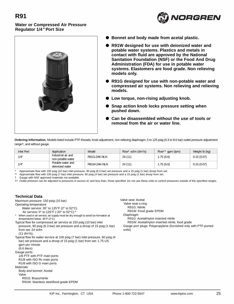
● Bonnet and body made from acetal plastic.
● R91W designed for use with deionized water andpotable water systems. Plastics and metals incontact with fluid are approved by the NationalSanitation Foundation (NSF) or the Food And DrugAdministration (FDA) for use in potable watersystems. Elastomers are food grade. Non relievingmodels only.
● R91G designed for use with non-potable water andcompressed air systems. Non relieving and relievingmodels.
● Low torque, non-rising adjusting knob.
● Snap action knob locks pressure setting whenpushed down.
● Can be disassembled without the use of tools orremoval from the air or water line.
R91Water or Compressed Air PressureRegulator 1/4" Port Size
25
Technical DataMaximum pressure: 150 psig (10 bar)Operating temperature
Water service: 35° to 125°F (2° to 52°C) Air service: 0° to 125°F (-20° to 52°C) *
* When used in air service, air supply must be dry enough to avoid ice formation attemperatures below 35°F (2°C).
Typical flow for compressed air service at 150 psig (10 bar) inletpressure, 90 psig (6.3 bar) set pressure and a droop of 15 psig (1 bar)from set: 24 scfm (11 dm3/s).
Typical flow for water service at 100 psig (7 bar) inlet pressure, 60 psig (4bar) set pressure and a droop of 15 psig (1 bar) from set: 1.75 USgpm per minute (6.6 liters)
Gauge ports:1/8 PTF with PTF main portsR1/8 with ISO Rc main portsR1/8 with ISO G main ports
MaterialsBody and bonnet: AcetalValve
R91G: Brass/nitrileR91W: Stainless steel/food grade EPDM
Valve seat: AcetalValve seat o-ring
R91G: NitrileR91W: Food grade EPDM
DiaphragmR91G: Acetal/nylon inserted nitrileR91W: Acetal/nylon inserted nitrile, food grade
Gauge port plugs: Polypropylene (furnished only with PTF-portedunits)
Ordering Information. Models listed include PTF threads, knob adjustment, non relieving diaphragm, 5 to 125 psig (0.3 to 8.6 bar) outlet pressure adjustmentrange†, and without gauge.
Inlet Port Application Model Flow* scfm (dm3/s) Flow** gpm (lpm) Weight lb (kg)
1/4" Industrial air and R91G-2AK-NLN 24 (11) 1.75 (6.6) 0.15 (0.07)non-potable water
1/4" Potable water and R91W-2AK-NLN 24 (11) 1.75 (6.6) 0.15 (0.07)deionized water
* Approximate flow with 150 psig (10 bar) inlet pressure, 90 psig (6.3 bar) set pressure and a 15 psig (1 bar) droop from set.** Approximate flow with 100 psig (7 bar) inlet pressure, 60 psig (4 bar) set pressure and a 15 psig (1 bar) droop from set.† Gauge with NSF approved materials not available.†† Outlet pressure can be adjusted to pressures in excess of, and less than, those specified. Do not use these units to control pressures outside of the specified ranges.
26
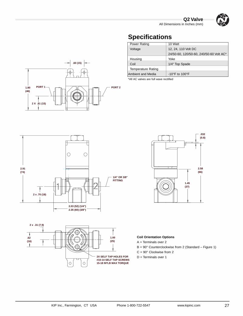
Q2 Valve
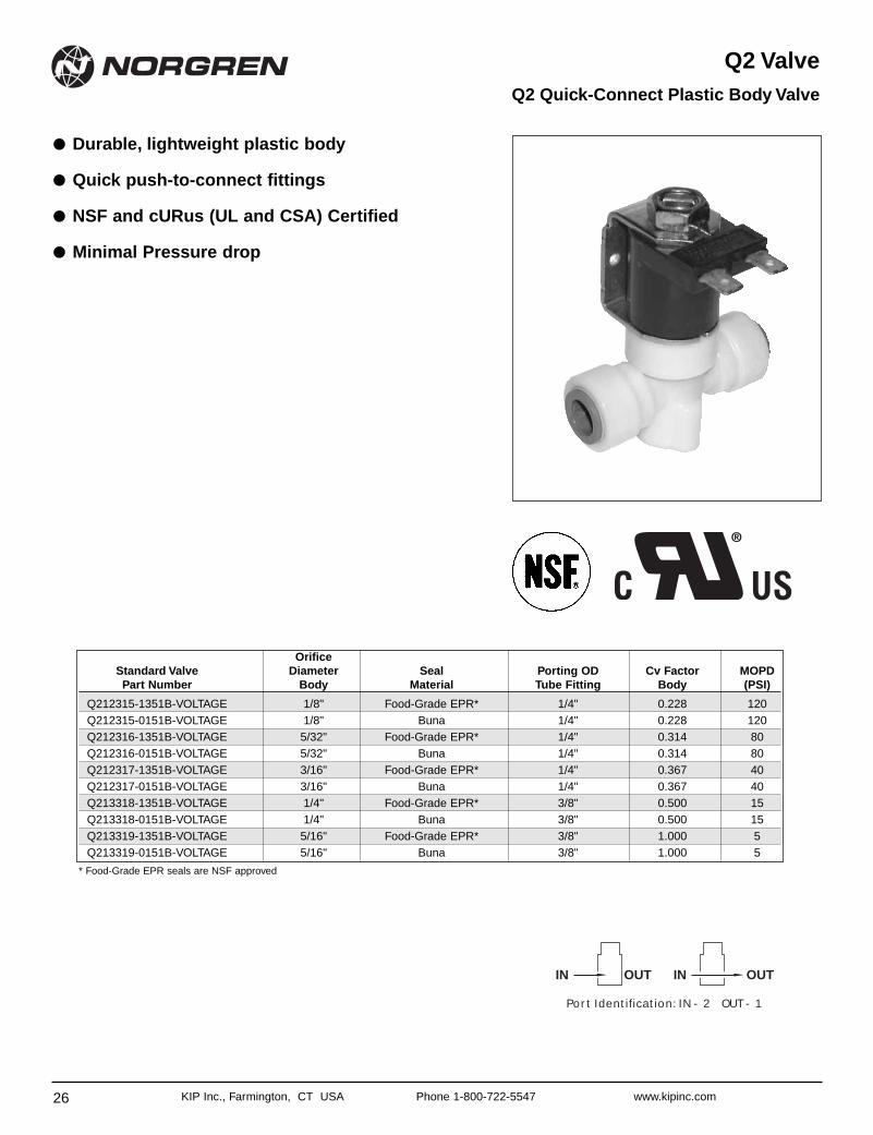
● Durable, lightweight plastic body
● Quick push-to-connect fittings
● NSF and cURus (UL and CSA) Certified
● Minimal Pressure drop
Q2 Quick-Connect Plastic Body Valve
KIP Inc., Farmington, CT USA Phone 1-800-722-5547 www.kipinc.com
OrificeStandard Valve Diameter Seal Porting OD Cv Factor MOPDPart Number Body Material Tube Fitting Body (PSI)
Q212315-1351B-VOLTAGE 1/8" Food-Grade EPR* 1/4" 0.228 120Q212315-0151B-VOLTAGE 1/8" Buna 1/4" 0.228 120Q212316-1351B-VOLTAGE 5/32" Food-Grade EPR* 1/4" 0.314 80Q212316-0151B-VOLTAGE 5/32" Buna 1/4" 0.314 80Q212317-1351B-VOLTAGE 3/16" Food-Grade EPR* 1/4" 0.367 40Q212317-0151B-VOLTAGE 3/16" Buna 1/4" 0.367 40Q213318-1351B-VOLTAGE 1/4" Food-Grade EPR* 3/8" 0.500 15Q213318-0151B-VOLTAGE 1/4" Buna 3/8" 0.500 15Q213319-1351B-VOLTAGE 5/16" Food-Grade EPR* 3/8" 1.000 5Q213319-0151B-VOLTAGE 5/16" Buna 3/8" 1.000 5
OUTINOUTIN
Port Identification: IN - 2 OUT - 1
* Food-Grade EPR seals are NSF approved
Q2 Valve
27
All Dimensions in Inches (mm)
KIP Inc., Farmington, CT USA Phone 1-800-722-5547 www.kipinc.com
0.72
2 x .31 (7.9)
2 X .61 (15)
PORT 2PORT 1
1.00(25)
2.03 (52) (1/4")2.35 (60) (3/8")
.62(16)
2X SELF TAP HOLES FOR#10-14 SELF TAP SCREWS15-18 IN*LB MAX TORQUE
2.91(74)
2 x .70 (18)
1/4" OR 3/8" FITTING
2.58(66)
.60 (15)
1.80(46)
.032(0.8)
1.45(37)
Power Rating 10 Watt
Voltage 12, 24, 110 Volt DC
24/50-60, 120/50-60, 240/50-60 Volt AC*
Housing Yoke
Coil 1/4" Top Spade
Temperature Rating
Ambient and Media -10°F to 100°F
Coil Orientation Options
A = Terminals over 2
B = 90° Counterclockwise from 2 (Standard – Figure 1)
C = 90° Clockwise from 2
D = Terminals over 1
*All AC valves are full wave rectified
Specifications
28 KIP Inc., Farmington, CT USA Phone 1-800-722-5547 www.kipinc.com
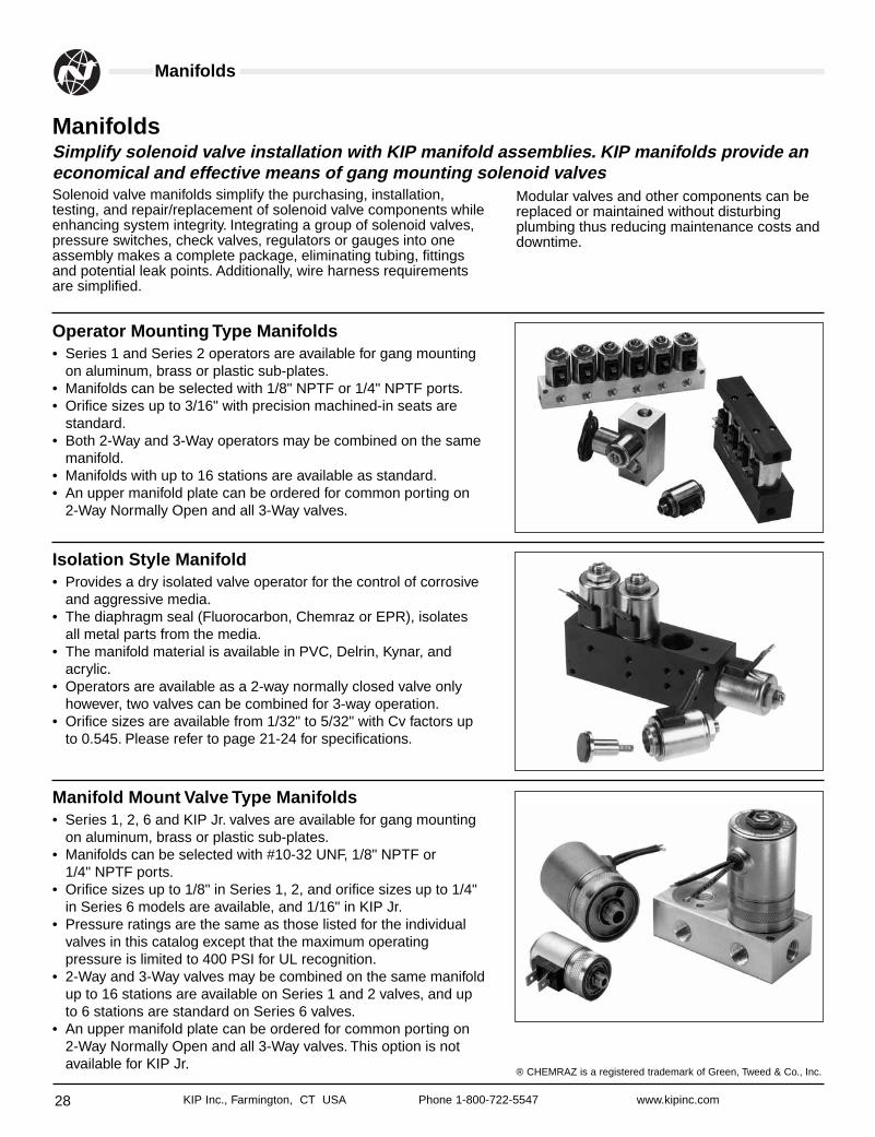
Manifolds
Operator Mounting Type Manifolds• Series 1 and Series 2 operators are available for gang mounting
on aluminum, brass or plastic sub-plates.• Manifolds can be selected with 1/8" NPTF or 1/4" NPTF ports.• Orifice sizes up to 3/16" with precision machined-in seats are
standard.• Both 2-Way and 3-Way operators may be combined on the same
manifold.• Manifolds with up to 16 stations are available as standard.• An upper manifold plate can be ordered for common porting on
2-Way Normally Open and all 3-Way valves.
Isolation Style Manifold• Provides a dry isolated valve operator for the control of corrosive
and aggressive media.• The diaphragm seal (Fluorocarbon, Chemraz or EPR), isolates
all metal parts from the media.• The manifold material is available in PVC, Delrin, Kynar, and
acrylic.• Operators are available as a 2-way normally closed valve only
however, two valves can be combined for 3-way operation.• Orifice sizes are available from 1/32" to 5/32" with Cv factors up
to 0.545. Please refer to page 21-24 for specifications.
Manifold Mount Valve Type Manifolds• Series 1, 2, 6 and KIP Jr. valves are available for gang mounting
on aluminum, brass or plastic sub-plates.• Manifolds can be selected with #10-32 UNF, 1/8" NPTF or
1/4" NPTF ports.• Orifice sizes up to 1/8" in Series 1, 2, and orifice sizes up to 1/4"
in Series 6 models are available, and 1/16" in KIP Jr.• Pressure ratings are the same as those listed for the individual
valves in this catalog except that the maximum operatingpressure is limited to 400 PSI for UL recognition.
• 2-Way and 3-Way valves may be combined on the same manifoldup to 16 stations are available on Series 1 and 2 valves, and upto 6 stations are standard on Series 6 valves.
• An upper manifold plate can be ordered for common porting on2-Way Normally Open and all 3-Way valves. This option is notavailable for KIP Jr.
Solenoid valve manifolds simplify the purchasing, installation,testing, and repair/replacement of solenoid valve components whileenhancing system integrity. Integrating a group of solenoid valves,pressure switches, check valves, regulators or gauges into oneassembly makes a complete package, eliminating tubing, fittingsand potential leak points. Additionally, wire harness requirementsare simplified.
ManifoldsSimplify solenoid valve installation with KIP manifold assemblies. KIP manifolds provide aneconomical and effective means of gang mounting solenoid valves
Modular valves and other components can bereplaced or maintained without disturbingplumbing thus reducing maintenance costs anddowntime.
® CHEMRAZ is a registered trademark of Green, Tweed & Co., Inc.
29KIP Inc., Farmington, CT USA Phone 1-800-722-5547 www.kipinc.com
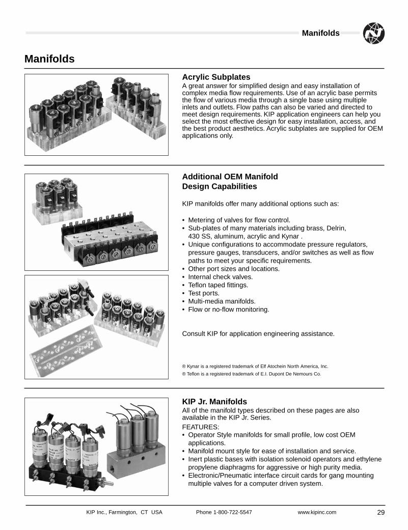
Manifolds
Acrylic SubplatesA great answer for simplified design and easy installation ofcomplex media flow requirements. Use of an acrylic base permitsthe flow of various media through a single base using multipleinlets and outlets. Flow paths can also be varied and directed tomeet design requirements. KIP application engineers can help youselect the most effective design for easy installation, access, andthe best product aesthetics. Acrylic subplates are supplied for OEMapplications only.
Additional OEM ManifoldDesign Capabilities
KIP manifolds offer many additional options such as:
• Metering of valves for flow control.• Sub-plates of many materials including brass, Delrin,
430 SS, aluminum, acrylic and Kynar .• Unique configurations to accommodate pressure regulators,
pressure gauges, transducers, and/or switches as well as flowpaths to meet your specific requirements.
• Other port sizes and locations.• Internal check valves.• Teflon taped fittings.• Test ports.• Multi-media manifolds.• Flow or no-flow monitoring.
Consult KIP for application engineering assistance.
® Kynar is a registered trademark of Elf Atochein North America, Inc.
® Teflon is a registered trademark of E.I. Dupont De Nemours Co.
KIP Jr. ManifoldsAll of the manifold types described on these pages are alsoavailable in the KIP Jr. Series.FEATURES:• Operator Style manifolds for small profile, low cost OEM
applications.• Manifold mount style for ease of installation and service.• Inert plastic bases with isolation solenoid operators and ethylene
propylene diaphragms for aggressive or high purity media.• Electronic/Pneumatic interface circuit cards for gang mounting
multiple valves for a computer driven system.
Manifolds
30 KIP Inc., Farmington, CT USA Phone 1-800-722-5547 www.kipinc.com
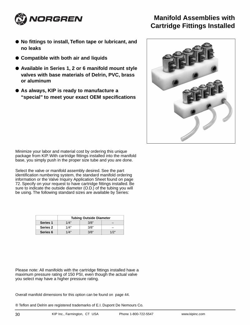
Manifold Assemblies withCartridge Fittings Installed
● No fittings to install, Teflon tape or lubricant, andno leaks
● Compatible with both air and liquids
● Available in Series 1, 2 or 6 manifold mount stylevalves with base materials of Delrin, PVC, brassor aluminum
● As always, KIP is ready to manufacture a“special” to meet your exact OEM specifications
Tubing Outside DiameterSeries 1 1/4" 3/8" –Series 2 1/4" 3/8" –Series 6 1/4" 3/8" 1/2"
Please note: All manifolds with the cartridge fittings installed have amaximum pressure rating of 150 PSI, even though the actual valveyou select may have a higher pressure rating.
Overall manifold dimensions for this option can be found on page 44.
® Teflon and Delrin are registered trademarks of E.I. Dupont De Nemours Co.
Minimize your labor and material cost by ordering this uniquepackage from KIP. With cartridge fittings installed into the manifoldbase, you simply push in the proper size tube and you are done.
Select the valve or manifold assembly desired. See the partidentification numbering system, the standard manifold orderinginformation or the Valve Inquiry Application Sheet found on page72. Specify on your request to have cartridge fittings installed. Besure to indicate the outside diameter (O.D.) of the tubing you willbe using. The following standard sizes are available by Series:
31KIP Inc., Farmington, CT USA Phone 1-800-722-5547 www.kipinc.comKIP Inc., Farmington, CT USA Phone 1-800-722-5547 www.kipinc.com
Manifolds
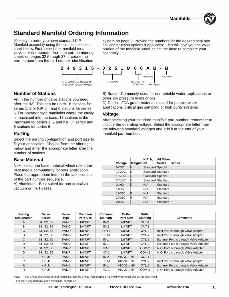
It’s easy to order your own standard KIPManifold assembly using the simple selectionchart below. First, select the manifold mountvalve or valve operator from the part numberingcharts on pages 32 through 37 or create thepart number from the part number identification
Number of StationsFill in the number of valve stations you needafter the “M”. This can be up to 16 stations forseries 1, 2 or KIP Jr., and 6 stations for series6. For operator style manifolds where the cavityis machined into the base, 16 stations is themaximum for series 1, 2 and KIP Jr. series and6 stations for series 6.
PortingSelect the porting configuration and port size tofit your application. Choose from the offeringsbelow and enter the appropriate letter after thenumber of stations.
Base Material Next, select the base material which offers thebest media compatibility for your application.Place the appropriate letter in the last positionof the part number sequence.A) Aluminum - Best suited for non-critical air,vacuum or inert gases.
Standard Manifold Ordering Information
STD. MANIFOLD MOUNT OROPERATOR VALVE NUMBER
OPTIONAL NUMBER OFSTATIONS
PORTING VOLTAGE
MATERIAL
2 4 9 3 1 5 - 0 2 5 1 M 0 6 A B - B
Porting Valve Valve Common Common Outlet OutletDesignation Series Type Port Size Marking Port Size Marking Comments
A S1, S2, S6 2WNC 1/8"NPT IN-2 1/8"NPT OUT-1B S1, S2, S6 2WNC 1/4"NPT IN-2 1/4"NPT OUT-1C S1, S2, S6 3WNO 1/8"NPT EXH-1 1/8"NPT CYL-2 Inlet Port is through Valve AdapterD S1, S2, S6 3WNO 1/4"NPT EXH-1 1/4"NPT CYL-2 Inlet Port is through Valve AdapterC S1, S2, S6 3WNC 1/8"NPT IN-1 1/8"NPT CYL-2 Exhaust Port is through Valve AdapterD S1, S2, S6 3WNC 1/4"NPT IN-1 1/4"NPT CYL-2 Exhaust Port is through Valve AdapterC S1, S2, S6 3WMP 1/8"NPT NC-1 1/8"NPT COM-2 N.O. Port is through Valve AdapterD S1, S2, S6 3WMP 1/4"NPT NC-1 1/4"NPT COM-2 N.O. Port is through Valve AdapterJ KIP Jr. 2WNC 1/8"NPT IN-2 #10-32 UNF OUT-1R KIP Jr. 3WNO 1/8"NPT EXH-1 #10-32 UNF CYL-2 Inlet Port is through Valve AdapterR KIP Jr. 3WNC 1/8"NPT IN-1 #10-32 UNF CYL-2 Exhaust Port is through Valve AdapterR KIP Jr. 3WMP 1/8"NPT NC-1 #10-32 UNF COM-2 N.O. Port is through Valve Adapter
Note: For 3-way directional control manifolds, use the 3-way multi-purpose manifold which most closely fits your need.
For the 2-way normally open manifolds, consult KIP.
system on page 9. Provide the numbers for the desired seal andcoil construction options if applicable. This will give you the valveportion of the manifold. Now, select the base to complete yourassembly.
B) Brass - Commonly used for non-potable water applications orother low pressure fluids or oils.D) Delrin - FDA grade material is used for potable waterapplications, critical gas sampling or high purity systems.
VoltageAfter selecting your standard manifold part number, remember toinclude the operating voltage. Select the appropriate letter fromthe following standard voltages and add it at the end of yourmanifold part number:
KIP Jr. All OtherVoltage Designation Series Series5VDC A Standard Special12VDC B Standard Standard15VDC C Standard Special24VDC D Standard Standard24/60 E N/A Standard110/50 F N/A Standard120/60 G N/A Standard220/50 H N/A Standard240/60 I N/A Standard
32 KIP Inc., Farmington, CT USA Phone 1-800-722-5547 www.kipinc.com
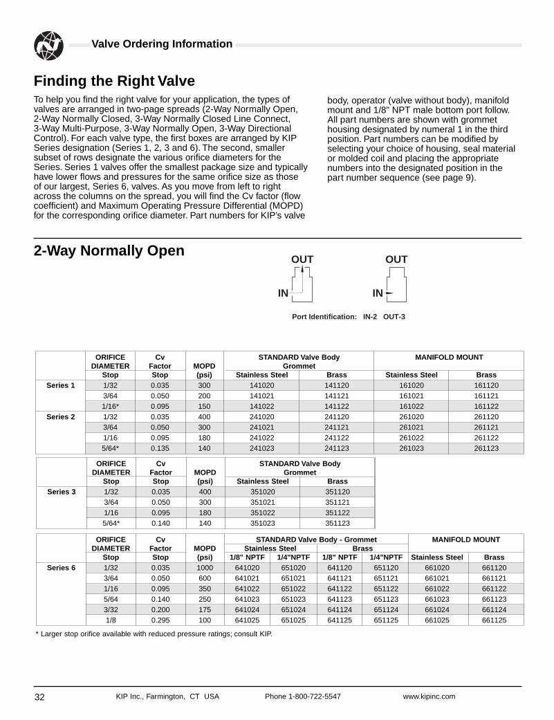
Valve Ordering Information
To help you find the right valve for your application, the types ofvalves are arranged in two-page spreads (2-Way Normally Open,2-Way Normally Closed, 3-Way Normally Closed Line Connect, 3-Way Multi-Purpose, 3-Way Normally Open, 3-Way DirectionalControl). For each valve type, the first boxes are arranged by KIPSeries designation (Series 1, 2, 3 and 6). The second, smallersubset of rows designate the various orifice diameters for theSeries. Series 1 valves offer the smallest package size and typicallyhave lower flows and pressures for the same orifice size as thoseof our largest, Series 6, valves. As you move from left to rightacross the columns on the spread, you will find the Cv factor (flowcoefficient) and Maximum Operating Pressure Differential (MOPD)for the corresponding orifice diameter. Part numbers for KIP’s valve
Finding the Right Valve
2-Way Normally OpenOUT OUT
Port Identification: IN-2 OUT-3
IN IN
body, operator (valve without body), manifoldmount and 1/8" NPT male bottom port follow.All part numbers are shown with grommethousing designated by numeral 1 in the thirdposition. Part numbers can be modified byselecting your choice of housing, seal materialor molded coil and placing the appropriatenumbers into the designated position in thepart number sequence (see page 9).
ORIFICE Cv STANDARD Valve Body MANIFOLD MOUNTDIAMETER Factor MOPD Grommet
Stop Stop (psi) Stainless Steel Brass Stainless Steel BrassSeries 1 1/32 0.035 300 141020 141120 161020 161120
3/64 0.050 200 141021 141121 161021 1611211/16* 0.095 150 141022 141122 161022 161122
Series 2 1/32 0.035 400 241020 241120 261020 2611203/64 0.050 300 241021 241121 261021 2611211/16 0.095 180 241022 241122 261022 2611225/64* 0.135 140 241023 241123 261023 261123
ORIFICE Cv STANDARD Valve BodyDIAMETER Factor MOPD Grommet
Stop Stop (psi) Stainless Steel BrassSeries 3 1/32 0.035 400 351020 351120
3/64 0.050 300 351021 3511211/16 0.095 180 351022 3511225/64* 0.140 140 351023 351123
ORIFICE Cv STANDARD Valve Body - Grommet MANIFOLD MOUNTDIAMETER Factor MOPD Stainless Steel Brass
Stop Stop (psi) 1/8" NPTF 1/4"NPTF 1/8" NPTF 1/4"NPTF Stainless Steel BrassSeries 6 1/32 0.035 1000 641020 651020 641120 651120 661020 661120
3/64 0.050 600 641021 651021 641121 651121 661021 6611211/16 0.095 350 641022 651022 641122 651122 661022 6611225/64 0.140 250 641023 651023 641123 651123 661023 6611233/32 0.200 175 641024 651024 641124 651124 661024 6611241/8 0.295 100 641025 651025 641125 651125 661025 661125
* Larger stop orifice available with reduced pressure ratings; consult KIP.
33KIP Inc., Farmington, CT USA Phone 1-800-722-5547 www.kipinc.com
Valve Ordering Information
ORIFICE Cv STANDARD Valve LOW WATT SpecificationsDIAMETER Factor MOPD Body - Grommet Cv Factor 1.5 Watt 2.0 Watt 2.5 Watt 3.0 Watt
Body Body (psi) SS Brass Body A B C DSeries 3 1/32 0.035 1000 351010 351110 0.030 300 540 780 1000
3/64 0.050 600 351011 351111 0.050 50 125 240 3401/16 0.095 400 351012 351112 0.085 15 60 100 1605/64 0.140 300 351013 351113 0.125 5 30 55 953/32 0.185 250 351014 351114 0.180 3 20 40 551/8 0.265 150 351015 351115 0.225 - 12 25 355/32 0.330 100 351016 351116 0.280 - 7 14 203/16 0.385 40 351017 351117 - - - - -1/4 0.450 15 351018 351118 - - - - -
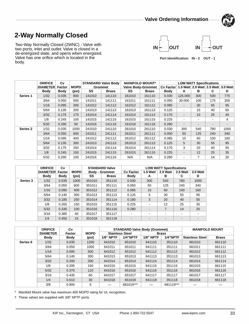
Two-Way Normally Closed (2WNC) - Valve withtwo ports, inlet and outlet. Valve is closed in ade-energized state, and opens when energized.Valve has one orifice which is located in thebody.
2-Way Normally Closed
OUTINOUTIN
Port Identification: IN - 2 OUT - 1
ORIFICE Cv STANDARD Valve Body MANIFOLD MOUNT* LOW WATT SpecificationsDIAMETER Factor MOPD Grommet Valve Body-Grommet Cv Factor 1.5 Watt 2.0 Watt 2.5 Watt 3.0 Watt
Body Body (psi) SS Brass SS Brass Body A B C DSeries 1 1/32 0.035 800 141010 141110 161010 161110 0.030 125.000 300 500 775
3/64 0.050 500 141011 141111 161011 161111 0.050 30.000 100 175 3001/16 0.095 300 141012 141112 161012 161112 0.085 - 30 65 955/64 0.135 200 141013 141113 161013 161113 0.125 - 15 40 653/32 0.175 175 141014 141114 161014 161114 0.170 - 10 25 401/8 0.245 100 141015 141115 161015 161115 0.225 - - - 45/32 0.290 50 141016 141116 161016 161116 0.280 - - - -
Series 2 1/32 0.035 1000 241010 241110 261010 261110 0.030 300 540 780 10003/64 0.050 600 241011 241111 261011 261111 0.050 50 125 240 3401/16 0.095 400 241012 241112 261012 261112 0.085 15 60 100 1605/64 0.135 300 241013 241113 261013 261113 0.125 5 30 55 953/32 0.175 250 241014 241114 261014 261114 0.170 3 20 40 551/8 0.245 150 241015 241115 261015 261115 0.225 - 12 25 355/32 0.290 100 241016 241116 N/A N/A 0.280 - 7 14 20
* Manifold Mount valve has maximum 400 MOPD rating for UL recognition.
† These valves are supplied with 3/8" NPTF ports.
ORIFICE Cv STANDARD Valve Body (Grommet) MANIFOLD MOUNTDIAMETER Factor MOPD Stainless Steel Brass
Body Body (psi) 1/8" NPTF 1/4"NPTF 1/8" NPTF 1/4"NPTF Stainless Steel BrassSeries 6 1/32 0.035 1200 641010 651010 641110 351110 661010 661110
3/64 0.050 1000 641011 651011 641111 351111 661011 6611111/16 0.095 500 641012 651012 641112 351112 661012 6611125/64 0.140 300 641013 651013 641113 351113 661013 6611133/32 0.200 200 641014 651014 641114 351114 661014 6611141/8 0.295 150 641015 651015 641115 351115 661015 6611155/32 0.370 110 641016 651016 641116 351116 661016 6611163/16 0.435 60 641017 651017 641117 351117 661017 6611171/4 0.610 30 641018 651018 641118 351118 661018 6611183/8 0.900 5 — 681019*** — 681119*** — —
34 KIP Inc., Farmington, CT USA Phone 1-800-722-5547 www.kipinc.com
Valve Ordering Information
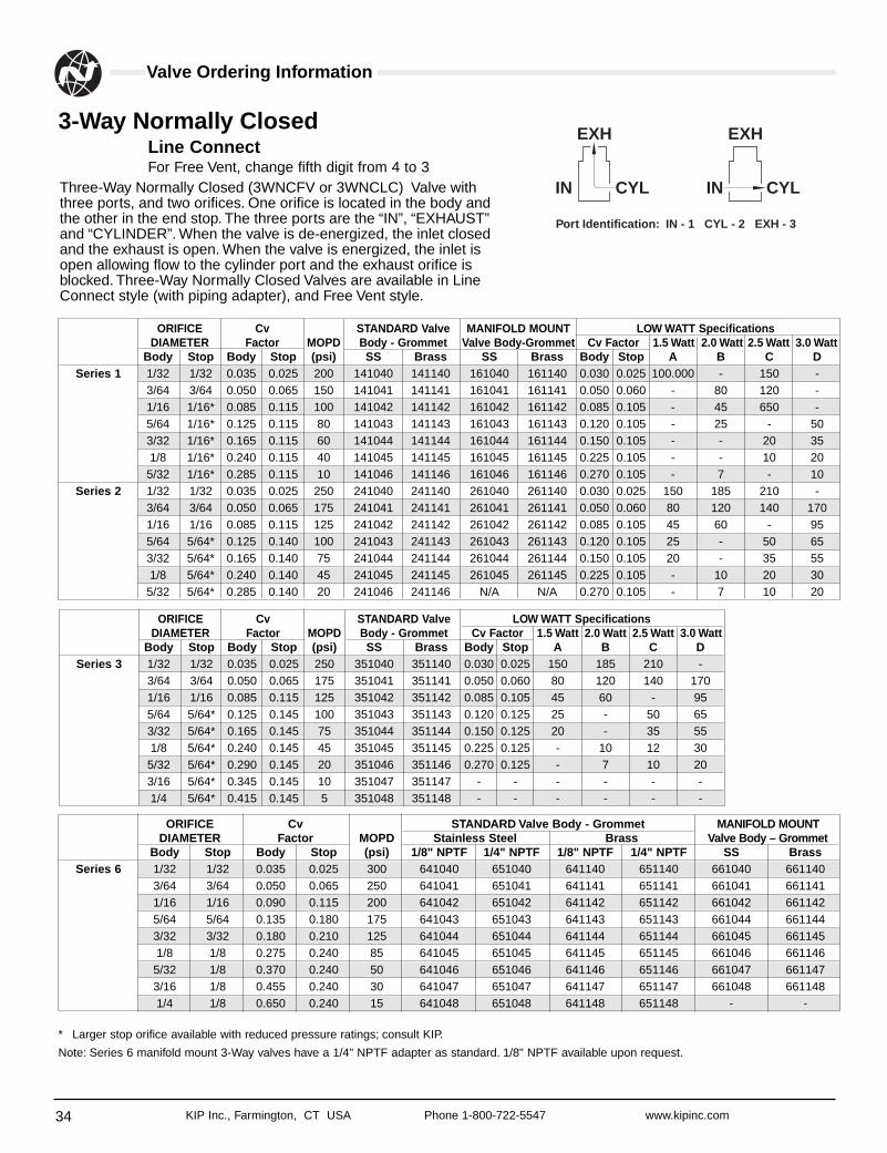
Three-Way Normally Closed (3WNCFV or 3WNCLC) Valve withthree ports, and two orifices. One orifice is located in the body andthe other in the end stop. The three ports are the “IN”, “EXHAUST”and “CYLINDER”. When the valve is de-energized, the inlet closedand the exhaust is open. When the valve is energized, the inlet isopen allowing flow to the cylinder port and the exhaust orifice isblocked. Three-Way Normally Closed Valves are available in LineConnect style (with piping adapter), and Free Vent style.
3-Way Normally ClosedLine ConnectFor Free Vent, change fifth digit from 4 to 3
EXH
IN CYL
EXH
IN CYL
Port Identification: IN - 1 CYL - 2 EXH - 3
ORIFICE Cv STANDARD Valve MANIFOLD MOUNT LOW WATT SpecificationsDIAMETER Factor MOPD Body - Grommet Valve Body-Grommet Cv Factor 1.5 Watt 2.0 Watt 2.5 Watt 3.0 Watt
Body Stop Body Stop (psi) SS Brass SS Brass Body Stop A B C DSeries 1 1/32 1/32 0.035 0.025 200 141040 141140 161040 161140 0.030 0.025 100.000 - 150 -
3/64 3/64 0.050 0.065 150 141041 141141 161041 161141 0.050 0.060 - 80 120 -1/16 1/16* 0.085 0.115 100 141042 141142 161042 161142 0.085 0.105 - 45 650 -5/64 1/16* 0.125 0.115 80 141043 141143 161043 161143 0.120 0.105 - 25 - 503/32 1/16* 0.165 0.115 60 141044 141144 161044 161144 0.150 0.105 - - 20 351/8 1/16* 0.240 0.115 40 141045 141145 161045 161145 0.225 0.105 - - 10 205/32 1/16* 0.285 0.115 10 141046 141146 161046 161146 0.270 0.105 - 7 - 10
Series 2 1/32 1/32 0.035 0.025 250 241040 241140 261040 261140 0.030 0.025 150 185 210 -3/64 3/64 0.050 0.065 175 241041 241141 261041 261141 0.050 0.060 80 120 140 1701/16 1/16 0.085 0.115 125 241042 241142 261042 261142 0.085 0.105 45 60 - 955/64 5/64* 0.125 0.140 100 241043 241143 261043 261143 0.120 0.105 25 - 50 653/32 5/64* 0.165 0.140 75 241044 241144 261044 261144 0.150 0.105 20 - 35 551/8 5/64* 0.240 0.140 45 241045 241145 261045 261145 0.225 0.105 - 10 20 305/32 5/64* 0.285 0.140 20 241046 241146 N/A N/A 0.270 0.105 - 7 10 20
ORIFICE Cv STANDARD Valve LOW WATT SpecificationsDIAMETER Factor MOPD Body - Grommet Cv Factor 1.5 Watt 2.0 Watt 2.5 Watt 3.0 Watt
Body Stop Body Stop (psi) SS Brass Body Stop A B C DSeries 3 1/32 1/32 0.035 0.025 250 351040 351140 0.030 0.025 150 185 210 -
3/64 3/64 0.050 0.065 175 351041 351141 0.050 0.060 80 120 140 1701/16 1/16 0.085 0.115 125 351042 351142 0.085 0.105 45 60 - 955/64 5/64* 0.125 0.145 100 351043 351143 0.120 0.125 25 - 50 653/32 5/64* 0.165 0.145 75 351044 351144 0.150 0.125 20 - 35 551/8 5/64* 0.240 0.145 45 351045 351145 0.225 0.125 - 10 12 305/32 5/64* 0.290 0.145 20 351046 351146 0.270 0.125 - 7 10 203/16 5/64* 0.345 0.145 10 351047 351147 - - - - - -1/4 5/64* 0.415 0.145 5 351048 351148 - - - - - -
ORIFICE Cv STANDARD Valve Body - Grommet MANIFOLD MOUNTDIAMETER Factor MOPD Stainless Steel Brass Valve Body – Grommet
Body Stop Body Stop (psi) 1/8" NPTF 1/4" NPTF 1/8" NPTF 1/4" NPTF SS BrassSeries 6 1/32 1/32 0.035 0.025 300 641040 651040 641140 651140 661040 661140
3/64 3/64 0.050 0.065 250 641041 651041 641141 651141 661041 6611411/16 1/16 0.090 0.115 200 641042 651042 641142 651142 661042 6611425/64 5/64 0.135 0.180 175 641043 651043 641143 651143 661044 6611443/32 3/32 0.180 0.210 125 641044 651044 641144 651144 661045 6611451/8 1/8 0.275 0.240 85 641045 651045 641145 651145 661046 6611465/32 1/8 0.370 0.240 50 641046 651046 641146 651146 661047 6611473/16 1/8 0.455 0.240 30 641047 651047 641147 651147 661048 6611481/4 1/8 0.650 0.240 15 641048 651048 641148 651148 - -
* Larger stop orifice available with reduced pressure ratings; consult KIP.
Note: Series 6 manifold mount 3-Way valves have a 1/4" NPTF adapter as standard. 1/8" NPTF available upon request.
35KIP Inc., Farmington, CT USA Phone 1-800-722-5547 www.kipinc.com
Valve Ordering Information
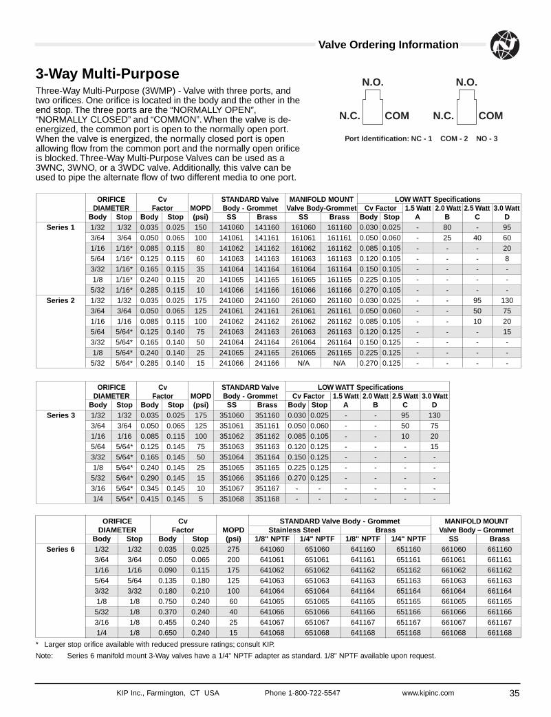
Three-Way Multi-Purpose (3WMP) - Valve with three ports, andtwo orifices. One orifice is located in the body and the other in theend stop. The three ports are the “NORMALLY OPEN”,“NORMALLY CLOSED” and “COMMON”. When the valve is de-energized, the common port is open to the normally open port.When the valve is energized, the normally closed port is openallowing flow from the common port and the normally open orificeis blocked. Three-Way Multi-Purpose Valves can be used as a3WNC, 3WNO, or a 3WDC valve. Additionally, this valve can beused to pipe the alternate flow of two different media to one port.
3-Way Multi-PurposeN.O.
N.C. COM
N.O.
N.C. COM
Port Identification: NC - 1 COM - 2 NO - 3
* Larger stop orifice available with reduced pressure ratings; consult KIP.
Note: Series 6 manifold mount 3-Way valves have a 1/4" NPTF adapter as standard. 1/8" NPTF available upon request.
ORIFICE Cv STANDARD Valve MANIFOLD MOUNT LOW WATT SpecificationsDIAMETER Factor MOPD Body - Grommet Valve Body-Grommet Cv Factor 1.5 Watt 2.0 Watt 2.5 Watt 3.0 Watt
Body Stop Body Stop (psi) SS Brass SS Brass Body Stop A B C DSeries 1 1/32 1/32 0.035 0.025 150 141060 141160 161060 161160 0.030 0.025 - 80 - 95
3/64 3/64 0.050 0.065 100 141061 141161 161061 161161 0.050 0.060 - 25 40 601/16 1/16* 0.085 0.115 80 141062 141162 161062 161162 0.085 0.105 - - - 205/64 1/16* 0.125 0.115 60 141063 141163 161063 161163 0.120 0.105 - - - 83/32 1/16* 0.165 0.115 35 141064 141164 161064 161164 0.150 0.105 - - - -1/8 1/16* 0.240 0.115 20 141065 141165 161065 161165 0.225 0.105 - - - -5/32 1/16* 0.285 0.115 10 141066 141166 161066 161166 0.270 0.105 - - - -
Series 2 1/32 1/32 0.035 0.025 175 241060 241160 261060 261160 0.030 0.025 - - 95 1303/64 3/64 0.050 0.065 125 241061 241161 261061 261161 0.050 0.060 - - 50 751/16 1/16 0.085 0.115 100 241062 241162 261062 261162 0.085 0.105 - - 10 205/64 5/64* 0.125 0.140 75 241063 241163 261063 261163 0.120 0.125 - - - 153/32 5/64* 0.165 0.140 50 241064 241164 261064 261164 0.150 0.125 - - - -1/8 5/64* 0.240 0.140 25 241065 241165 261065 261165 0.225 0.125 - - - -5/32 5/64* 0.285 0.140 15 241066 241166 N/A N/A 0.270 0.125 - - - -
ORIFICE Cv STANDARD Valve LOW WATT SpecificationsDIAMETER Factor MOPD Body - Grommet Cv Factor 1.5 Watt 2.0 Watt 2.5 Watt 3.0 Watt
Body Stop Body Stop (psi) SS Brass Body Stop A B C DSeries 3 1/32 1/32 0.035 0.025 175 351060 351160 0.030 0.025 - - 95 130
3/64 3/64 0.050 0.065 125 351061 351161 0.050 0.060 - - 50 751/16 1/16 0.085 0.115 100 351062 351162 0.085 0.105 - - 10 205/64 5/64* 0.125 0.145 75 351063 351163 0.120 0.125 - - - 153/32 5/64* 0.165 0.145 50 351064 351164 0.150 0.125 - - - -1/8 5/64* 0.240 0.145 25 351065 351165 0.225 0.125 - - - -5/32 5/64* 0.290 0.145 15 351066 351166 0.270 0.125 - - - -3/16 5/64* 0.345 0.145 10 351067 351167 - - - - - -1/4 5/64* 0.415 0.145 5 351068 351168 - - - - - -
ORIFICE Cv STANDARD Valve Body - Grommet MANIFOLD MOUNTDIAMETER Factor MOPD Stainless Steel Brass Valve Body – Grommet
Body Stop Body Stop (psi) 1/8" NPTF 1/4" NPTF 1/8" NPTF 1/4" NPTF SS BrassSeries 6 1/32 1/32 0.035 0.025 275 641060 651060 641160 651160 661060 661160
3/64 3/64 0.050 0.065 200 641061 651061 641161 651161 661061 6611611/16 1/16 0.090 0.115 175 641062 651062 641162 651162 661062 6611625/64 5/64 0.135 0.180 125 641063 651063 641163 651163 661063 6611633/32 3/32 0.180 0.210 100 641064 651064 641164 651164 661064 6611641/8 1/8 0.750 0.240 60 641065 651065 641165 651165 661065 6611655/32 1/8 0.370 0.240 40 641066 651066 641166 651166 661066 6611663/16 1/8 0.455 0.240 25 641067 651067 641167 651167 661067 6611671/4 1/8 0.650 0.240 15 641068 651068 641168 651168 661068 661168
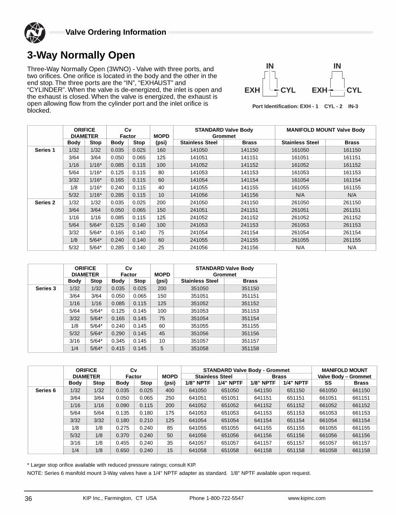
36 KIP Inc., Farmington, CT USA Phone 1-800-722-5547 www.kipinc.com
Valve Ordering Information
Three-Way Normally Open (3WNO) - Valve with three ports, andtwo orifices. One orifice is located in the body and the other in theend stop. The three ports are the “IN”, “EXHAUST” and“CYLINDER”. When the valve is de-energized, the inlet is open andthe exhaust is closed. When the valve is energized, the exhaust isopen allowing flow from the cylinder port and the inlet orifice isblocked.
3-Way Normally OpenIN
EXH CYL
IN
EXH CYL
Port Identification: EXH - 1 CYL - 2 IN-3
ORIFICE Cv STANDARD Valve Body MANIFOLD MOUNT Valve BodyDIAMETER Factor MOPD Grommet
Body Stop Body Stop (psi) Stainless Steel Brass Stainless Steel BrassSeries 1 1/32 1/32 0.035 0.025 160 141050 141150 161050 161150
3/64 3/64 0.050 0.065 125 141051 141151 161051 1611511/16 1/16* 0.085 0.115 100 141052 141152 161052 1611525/64 1/16* 0.125 0.115 80 141053 141153 161053 1611533/32 1/16* 0.165 0.115 60 141054 141154 161054 1611541/8 1/16* 0.240 0.115 40 141055 141155 161055 1611555/32 1/16* 0.285 0.115 10 141056 141156 N/A N/A
Series 2 1/32 1/32 0.035 0.025 200 241050 241150 261050 2611503/64 3/64 0.050 0.065 150 241051 241151 261051 2611511/16 1/16 0.085 0.115 125 241052 241152 261052 2611525/64 5/64* 0.125 0.140 100 241053 241153 261053 2611533/32 5/64* 0.165 0.140 75 241054 241154 261054 2611541/8 5/64* 0.240 0.140 60 241055 241155 261055 2611555/32 5/64* 0.285 0.140 25 241056 241156 N/A N/A
ORIFICE Cv STANDARD Valve BodyDIAMETER Factor MOPD Grommet
Body Stop Body Stop (psi) Stainless Steel BrassSeries 3 1/32 1/32 0.035 0.025 200 351050 351150
3/64 3/64 0.050 0.065 150 351051 3511511/16 1/16 0.085 0.115 125 351052 3511525/64 5/64* 0.125 0.145 100 351053 3511533/32 5/64* 0.165 0.145 75 351054 3511541/8 5/64* 0.240 0.145 60 351055 3511555/32 5/64* 0.290 0.145 45 351056 3511563/16 5/64* 0.345 0.145 10 351057 3511571/4 5/64* 0.415 0.145 5 351058 351158
* Larger stop orifice available with reduced pressure ratings; consult KIP.
NOTE: Series 6 manifold mount 3-Way valves have a 1/4" NPTF adapter as standard. 1/8" NPTF available upon request.
ORIFICE Cv STANDARD Valve Body - Grommet MANIFOLD MOUNTDIAMETER Factor MOPD Stainless Steel Brass Valve Body – Grommet
Body Stop Body Stop (psi) 1/8" NPTF 1/4" NPTF 1/8" NPTF 1/4" NPTF SS BrassSeries 6 1/32 1/32 0.035 0.025 400 641050 651050 641150 651150 661050 661150
3/64 3/64 0.050 0.065 250 641051 651051 641151 651151 661051 6611511/16 1/16 0.090 0.115 200 641052 651052 641152 651152 661052 6611525/64 5/64 0.135 0.180 175 641053 651053 641153 651153 661053 6611533/32 3/32 0.180 0.210 125 641054 651054 641154 651154 661054 6611541/8 1/8 0.275 0.240 85 641055 651055 641155 651155 661055 6611555/32 1/8 0.370 0.240 50 641056 651056 641156 651156 661056 6611563/16 1/8 0.455 0.240 35 641057 651057 641157 651157 661057 6611571/4 1/8 0.650 0.240 15 641058 651058 641158 651158 661058 661158
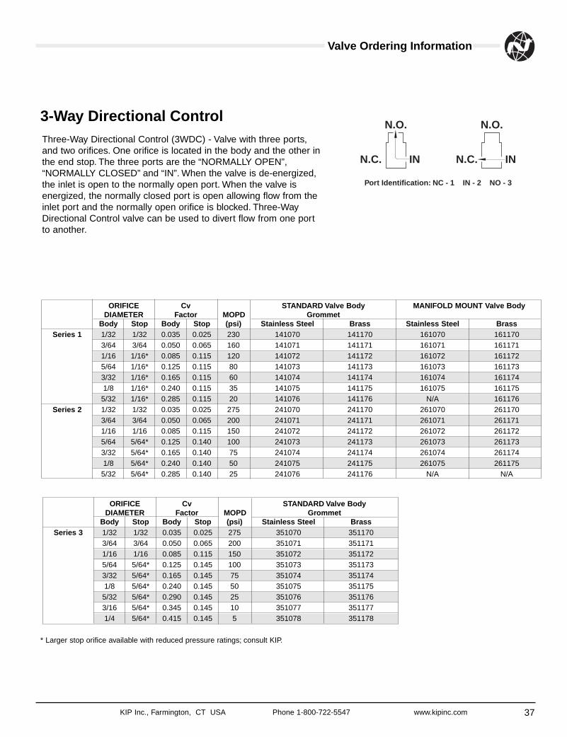
37KIP Inc., Farmington, CT USA Phone 1-800-722-5547 www.kipinc.com
Valve Ordering Information
Three-Way Directional Control (3WDC) - Valve with three ports,and two orifices. One orifice is located in the body and the other inthe end stop. The three ports are the “NORMALLY OPEN”,“NORMALLY CLOSED” and “IN”. When the valve is de-energized,the inlet is open to the normally open port. When the valve isenergized, the normally closed port is open allowing flow from theinlet port and the normally open orifice is blocked. Three-WayDirectional Control valve can be used to divert flow from one portto another.
3-Way Directional ControlN.O.
N.C. IN
N.O.
N.C. IN
Port Identification: NC - 1 IN - 2 NO - 3
* Larger stop orifice available with reduced pressure ratings; consult KIP.
ORIFICE Cv STANDARD Valve Body MANIFOLD MOUNT Valve BodyDIAMETER Factor MOPD Grommet
Body Stop Body Stop (psi) Stainless Steel Brass Stainless Steel BrassSeries 1 1/32 1/32 0.035 0.025 230 141070 141170 161070 161170
3/64 3/64 0.050 0.065 160 141071 141171 161071 1611711/16 1/16* 0.085 0.115 120 141072 141172 161072 1611725/64 1/16* 0.125 0.115 80 141073 141173 161073 1611733/32 1/16* 0.165 0.115 60 141074 141174 161074 1611741/8 1/16* 0.240 0.115 35 141075 141175 161075 1611755/32 1/16* 0.285 0.115 20 141076 141176 N/A 161176
Series 2 1/32 1/32 0.035 0.025 275 241070 241170 261070 2611703/64 3/64 0.050 0.065 200 241071 241171 261071 2611711/16 1/16 0.085 0.115 150 241072 241172 261072 2611725/64 5/64* 0.125 0.140 100 241073 241173 261073 2611733/32 5/64* 0.165 0.140 75 241074 241174 261074 2611741/8 5/64* 0.240 0.140 50 241075 241175 261075 2611755/32 5/64* 0.285 0.140 25 241076 241176 N/A N/A
ORIFICE Cv STANDARD Valve BodyDIAMETER Factor MOPD Grommet
Body Stop Body Stop (psi) Stainless Steel BrassSeries 3 1/32 1/32 0.035 0.025 275 351070 351170
3/64 3/64 0.050 0.065 200 351071 3511711/16 1/16 0.085 0.115 150 351072 3511725/64 5/64* 0.125 0.145 100 351073 3511733/32 5/64* 0.165 0.145 75 351074 3511741/8 5/64* 0.240 0.145 50 351075 3511755/32 5/64* 0.290 0.145 25 351076 3511763/16 5/64* 0.345 0.145 10 351077 3511771/4 5/64* 0.415 0.145 5 351078 351178
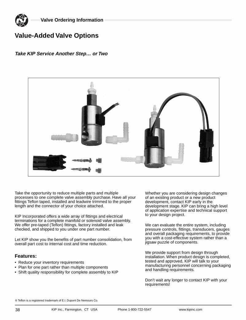
38 KIP Inc., Farmington, CT USA Phone 1-800-722-5547 www.kipinc.com
Valve Ordering Information
Take the opportunity to reduce multiple parts and multipleprocesses to one complete valve assembly purchase. Have all yourfittings Teflon taped, installed and leadwire trimmed to the properlength and the connector of your choice attached.
KIP Incorporated offers a wide array of fittings and electricalterminations for a complete manifold or solenoid valve assembly.We offer pre-taped (Teflon) fittings, factory installed and leakchecked, and shipped to you under one part number.
Let KIP show you the benefits of part number consolidation, fromoverall part cost to internal cost and time reduction.
Features:• Reduce your inventory requirements• Plan for one part rather than multiple components• Shift quality responsibility for complete assembly to KIP
Value-Added Valve Options
Take KIP Service Another Step… or Two
Whether you are considering design changesof an existing product or a new productdevelopment, contact KIP early in thedevelopment stage. KIP can bring a high levelof application expertise and technical supportto your design project.
We can evaluate the entire system, includingpressure controls, fittings, transducers, gaugesand overall packaging requirements, to provideyou with a cost-effective system rather than ajigsaw puzzle of components.
We provide support from design throughinstallation. When product design is completed,tested and approved, KIP will talk to yourmanufacturing personnel concerning packagingand handling requirements.
Don’t wait any longer to contact KIP with yourrequirements!
® Teflon is a registered trademark of E.I. Dupont De Nemours Co.
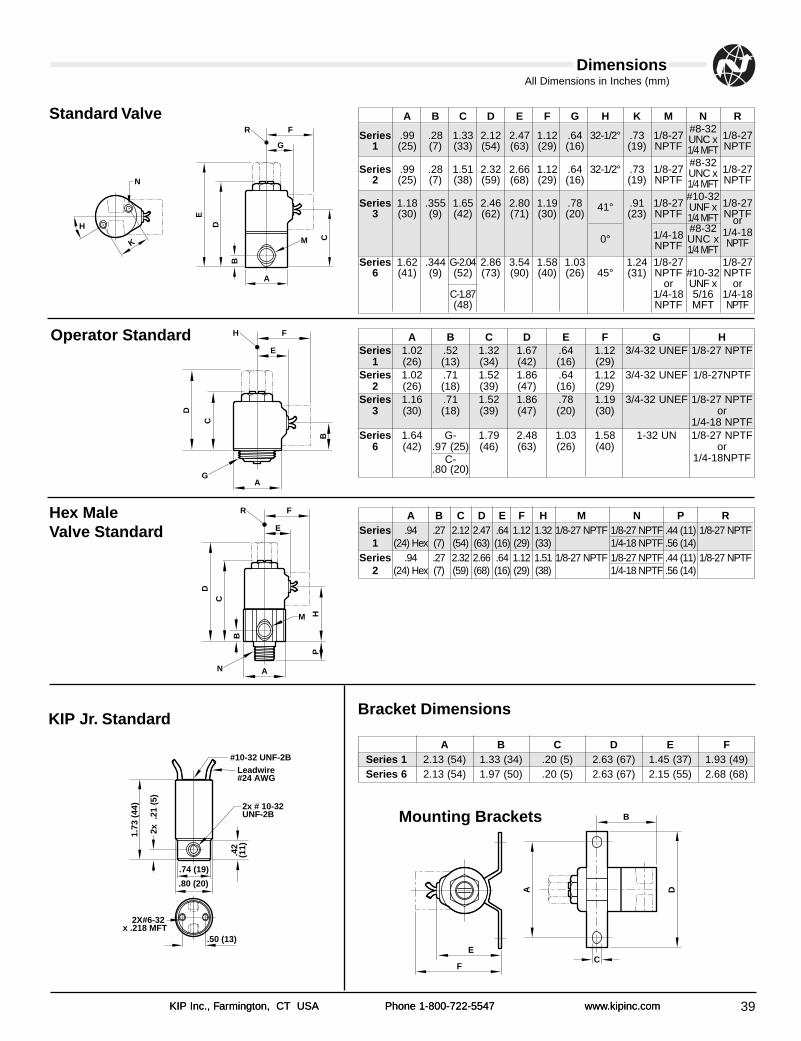
39
All Dimensions in Inches (mm)
KIP Inc., Farmington, CT USA Phone 1-800-722-5547 www.kipinc.comKIP Inc., Farmington, CT USA Phone 1-800-722-5547 www.kipinc.com
Dimensions
Standard Valve
N
H
K
E
D
C
B
FR
A
M
G
D
C
BFH
G
E
A
A B C D E F G H K M N R
Series .99 .28 1.33 2.12 2.47 1.12 .64 32-1/2° .73 1/8-27#8-32
1/8-271 (25) (7) (33) (54) (63) (29) (16) (19) NPTF
UNC xNPTF1/4 MFT
Series .99 .28 1.51 2.32 2.66 1.12 .64 32-1/2° .73 1/8-27#8-32
1/8-272 (25) (7) (38) (59) (68) (29) (16) (19) NPTF
UNC xNPTF1/4 MFT
Series 1.18 .355 1.65 2.46 2.80 1.19 .78 .91 1/8-27#10-32
1/8-273 (30) (9) (42) (62) (71) (30) (20)
41°(23) NPTF
UNF xNPTF1/4 MFT
1/4-18#8-32
or
0°NPTF
UNC x1/4-18
1/4 MFTNPTF
Series 1.62 .344 G-2.04 2.86 3.54 1.58 1.03 1.24 1/8-27 1/8-276 (41) (9) (52) (73) (90) (40) (26) 45° (31) NPTF #10-32 NPTF
or UNF x orC-1.87 1/4-18 5/16 1/4-18(48) NPTF MFT NPTF
A B C D E F H M N P RSeries .94 .27 2.12 2.47 .64 1.12 1.32 1/8-27 NPTF 1/8-27 NPTF .44 (11) 1/8-27 NPTF
1 (24) Hex (7) (54) (63) (16) (29) (33) 1/4-18 NPTF .56 (14)Series .94 .27 2.32 2.66 .64 1.12 1.51 1/8-27 NPTF 1/8-27 NPTF .44 (11) 1/8-27 NPTF
2 (24) Hex (7) (59) (68) (16) (29) (38) 1/4-18 NPTF .56 (14)
A B C D E FSeries 1 2.13 (54) 1.33 (34) .20 (5) 2.63 (67) 1.45 (37) 1.93 (49)Series 6 2.13 (54) 1.97 (50) .20 (5) 2.63 (67) 2.15 (55) 2.68 (68)
1.73
(44
)
2x .
21 (
5)
.50 (13)
2X#6-32 x .218 MFT
.42
(11)
2x # 10-32UNF-2B
Leadwire#24 AWG
#10-32 UNF-2B
.74 (19)
.80 (20)
D
C
B
HP
FR
N
E
A
M
Bracket Dimensions
Hex Male Valve Standard
Mounting Brackets
E
F
A D
C
B
Operator Standard A B C D E F G HSeries 1.02 .52 1.32 1.67 .64 1.12 3/4-32 UNEF 1/8-27 NPTF
1 (26) (13) (34) (42) (16) (29)Series 1.02 .71 1.52 1.86 .64 1.12 3/4-32 UNEF 1/8-27NPTF
2 (26) (18) (39) (47) (16) (29)Series 1.16 .71 1.52 1.86 .78 1.19 3/4-32 UNEF 1/8-27 NPTF
3 (30) (18) (39) (47) (20) (30) or1/4-18 NPTF
Series 1.64 G- 1.79 2.48 1.03 1.58 1-32 UN 1/8-27 NPTF6 (42) .97 (25) (46) (63) (26) (40) or
C- 1/4-18NPTF.80 (20)
KIP Jr. Standard
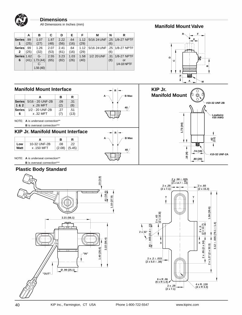
40
All Dimensions in Inches (mm)
KIP Inc., Farmington, CT USA Phone 1-800-722-5547 www.kipinc.com
DimensionsManifold Mount Valve
KIP Jr.Manifold Mount
Manifold Mount Interface
Plastic Body StandardD
C
N
B
FR
M
E
A
1.73
(44
)
.42
(11)
Leadwire#30 AWG
#10-32 UNF-2A.74 (19)
.80 (20)
#10-32 UNF-2B
.16
(4)
A B C D E F M N RSeries .99 1.07 1.87 2.22 .64 1.12 5/16 24UNF .25 1/8-27 NPTF
1 (25) (27) (48) (56) (16) (29) (6)Series .99 1.26 2.07 2.41 .64 1.12 5/16 24UNF .25 1/8-27 NPTF
2 (25) (32) (53) (61) (16) (29) (6)Series 1.62 G- 2.55 3.23 1.03 1.58 1/2 20UNF .31 1/8-27 NPTF
6 (41) 1.73 (44) (65) (82) (26) (40) (8) orC- 1/4-18 NPTF
1.56 (40)
A B RSeries 5/16 - 20 UNF-2B .09 .311 & 2 x .26 MFT (2) (8)
Series 1/2 - 20 UNF-2B .27 .516 x .32 MFT (7) (13)
A B Max
R
40
KIP Jr. Manifold Mount Interface
A B RLow 10-32 UNF-2B .08 .22Watt x .150 MFT (2.08) (5.45)
A B Max
R
40
NOTE: A is underseat connection**
B is overseat connection***
NOTE: A is underseat connection**
B is overseat connection***
1.40
(35
.6)
.15
(3.8
)
2.22
(56
.4)
.61
(15.
5)
1.10
(27
.9)
2.21 (56.1)
Ø .99 (25.1)
"IN"
"OUT"
2 x
.5
(2 x
12.
7)
.85
± .0
05 (2
1.6
± .1
3)
2 x
.43
(2 x
10.
8)
2 x
.95
(2 x
24)
1.56
(39
.6)
3.12
± .0
05 (
79.1
± 1
.4)
2 x
1.27
(2
x 32
.3)
2 x .58 ± .005(2 x 14.7 ± .13)
2 x .29 (2 x 7.1)
2 x .2 ± .015(2 x 5.0 ± .38)
6 x R .06(6 x R 1.4)
4 x R .130 (4 x R 3.3)
Y Y
2 x .29 (2 x 7.1)
2 x .60(2 x 15.3)
X X
2 x 32°
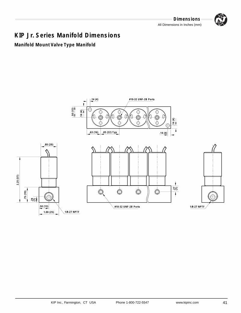
41
All Dimensions in Inches (mm)
KIP Inc., Farmington, CT USA Phone 1-800-722-5547 www.kipinc.com
Dimensions
KIP Jr. Series Manifold DimensionsManifold Mount Valve Type Manifold
.50
(13)
.14
(4)
.14 (4) #10-32 UNF-2B Ports
.63 (16) .85 (22) Typ
.14
(4)
.14 (4)
.27
(7)
2.25
(57
)
.75
(19)
.29
(7)
#10-32 UNF-2B Ports 1/8-27 NPTF
1/8-27 NPTF1.00 (25)
.80 (20)
.50 (13)
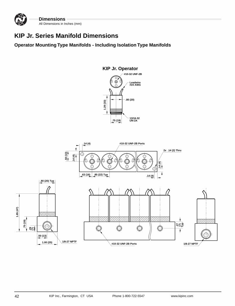
42
All Dimensions in Inches (mm)
KIP Inc., Farmington, CT USA Phone 1-800-722-5547 www.kipinc.com
Dimensions
KIP Jr. Series Manifold DimensionsOperator Mounting Type Manifolds - Including Isolation Type Manifolds
.50
(13)
.14
(4)
.14 (4) #10-32 UNF-2B Ports
2x .14 (2) Thru
.63 (16) .85 (22) Typ
.14
(4)
.14 (4).2
7(7
)T
yp
1.85
(47
)
.75
(19)
.29
(7)
#10-32 UNF-2B Ports 1/8-27 NPTF1/8-27 NPTF1.00 (25)
.80 (20) Typ
.50 (13)
13/16-32UN-2A
Leadwire#24 AWG
#10-32 UNF-2B
1.29
(33
)
.75 (19)
.80 (20)
KIP Jr. Operator
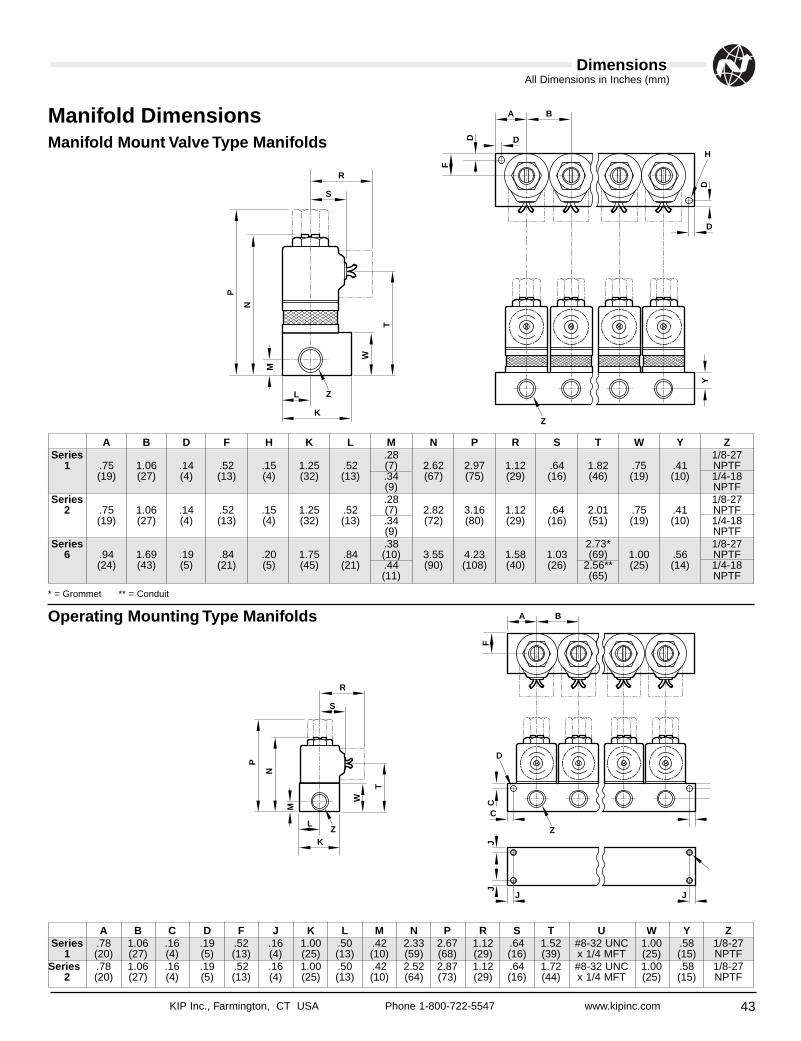
43
All Dimensions in Inches (mm)
KIP Inc., Farmington, CT USA Phone 1-800-722-5547 www.kipinc.com
Dimensions
Manifold DimensionsManifold Mount Valve Type Manifolds
Operating Mounting Type Manifolds
P
N
M
W
T
R
Z
Z
S
K
L
YD
D
H
D D
F
A B
P
N
M
W
T
R
Z
S
KZ
C
C
J J
J
D
F
A B
L
J
A B D F H K L M N P R S T W Y ZSeries .28 1/8-27
1 .75 1.06 .14 .52 .15 1.25 .52 (7) 2.62 2.97 1.12 .64 1.82 .75 .41 NPTF(19) (27) (4) (13) (4) (32) (13) .34 (67) (75) (29) (16) (46) (19) (10) 1/4-18
(9) NPTFSeries .28 1/8-27
2 .75 1.06 .14 .52 .15 1.25 .52 (7) 2.82 3.16 1.12 .64 2.01 .75 .41 NPTF(19) (27) (4) (13) (4) (32) (13) .34 (72) (80) (29) (16) (51) (19) (10) 1/4-18
(9) NPTFSeries .38 2.73* 1/8-27
6 .94 1.69 .19 .84 .20 1.75 .84 (10) 3.55 4.23 1.58 1.03 (69) 1.00 .56 NPTF(24) (43) (5) (21) (5) (45) (21) .44 (90) (108) (40) (26) 2.56** (25) (14) 1/4-18
(11) (65) NPTF
A B C D F J K L M N P R S T U W Y ZSeries .78 1.06 .16 .19 .52 .16 1.00 .50 .42 2.33 2.67 1.12 .64 1.52 #8-32 UNC 1.00 .58 1/8-27
1 (20) (27) (4) (5) (13) (4) (25) (13) (10) (59) (68) (29) (16) (39) x 1/4 MFT (25) (15) NPTFSeries .78 1.06 .16 .19 .52 .16 1.00 .50 .42 2.52 2.87 1.12 .64 1.72 #8-32 UNC 1.00 .58 1/8-27
2 (20) (27) (4) (5) (13) (4) (25) (13) (10) (64) (73) (29) (16) (44) x 1/4 MFT (25) (15) NPTF
* = Grommet ** = Conduit
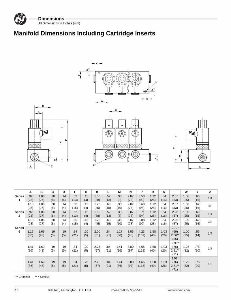
44
All Dimensions in Inches (mm)
KIP Inc., Farmington, CT USA Phone 1-800-722-5547 www.kipinc.com
Dimensions
Manifold Dimensions Including Cartridge Inserts
M
N
P
R
S
L Z Z
W
T
Y
K
F
D
C
A
B
D
C
H
A B C D F H K L M N P R S T W Y ZSeries .92 1.06 .30 .14 .52 .15 1.50 .52 .33 2.87 3.53 1.12 .64 2.07 1.00 .60
1/41 (23) (27) (8) (4) (13) (4) (38) (13) (8) (73) (90) (28) (16) (53) (25) (15)1.10 1.06 .30 .14 .60 .15 1.75 .60 .38 2.87 3.69 1.12 .64 2.07 1.00 .62
3/8(28) (27) (8) (4) (15) (4) (45) (15) (10) (73) (94) (28) (16) (53) (25) (16)Series .92 1.06 .30 .14 .52 .15 1.50 .52 .33 3.07 3.71 1.12 .64 2.26 1.00 .60
1/42 (23) (27) (8) (4) (13) (4) (38) (13) (8) (78) (94) (28) (16) (57) (25) (15)1.10 1.06 .30 .14 .60 .15 1.75 .60 .38 3.07 3.88 1.12 .64 2.26 1.00 .62
3/8(28) (27) (8) (4) (15) (4) (45) (15) (10) (78) (99) (28) (16) (57) (25) (16)Series 2.73*
6 1.17 1.69 .19 .19 .84 .20 2.00 .84 1.17 3.55 4.23 1.58 1.03 (69) 1.00 .551/4(30) (43) (5) (5) (21) (5) (51) (21) (30) (90) (107) (40) (26) 2.56** (25) (14)
(65)2.98*
1.41 1.69 .19 .19 .84 .20 2.25 .84 1.41 3.80 4.65 1.58 1.03 (76) 1.25 .783/8(36) (43) (5) (5) (21) (5) (57) (21) (36) (97) (118) (40) (26) 2.81** (32) (20)
(71)2.98*
1.41 1.69 .19 .19 .84 .20 2.25 .84 1.41 3.80 4.65 1.58 1.03 (76) 1.25 .781/2(36) (43) (5) (5) (21) (5) (57) (21) (36) (97) (118) (40) (26) 2.81** (32) (20)
(71)
* = Grommet ** = Conduit
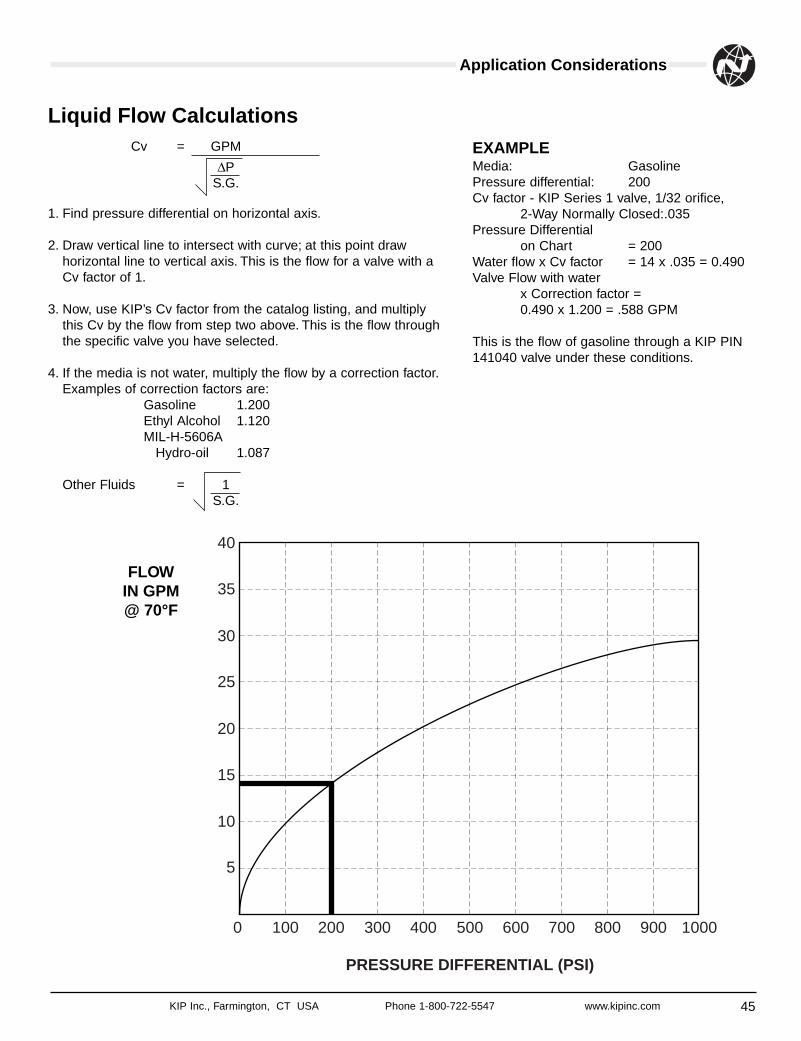
45KIP Inc., Farmington, CT USA Phone 1-800-722-5547 www.kipinc.com
Application Considerations
Cv = GPM
∆PS.G.
1. Find pressure differential on horizontal axis.
2. Draw vertical line to intersect with curve; at this point drawhorizontal line to vertical axis. This is the flow for a valve with aCv factor of 1.
3. Now, use KIP’s Cv factor from the catalog listing, and multiplythis Cv by the flow from step two above. This is the flow throughthe specific valve you have selected.
4. If the media is not water, multiply the flow by a correction factor.Examples of correction factors are:
Gasoline 1.200Ethyl Alcohol 1.120MIL-H-5606A
Hydro-oil 1.087
Other Fluids = 1S.G.
0
5
10
15
20
25
30
35
40
100 200 300 400 500
PRESSURE DIFFERENTIAL (PSI)
600 700 800 900 1000
FLOWIN GPM@ 70°F
Liquid Flow CalculationsEXAMPLEMedia: GasolinePressure differential: 200Cv factor - KIP Series 1 valve, 1/32 orifice,
2-Way Normally Closed:.035Pressure Differential
on Chart = 200Water flow x Cv factor = 14 x .035 = 0.490Valve Flow with water
x Correction factor = 0.490 x 1.200 = .588 GPM
This is the flow of gasoline through a KIP PIN141040 valve under these conditions.
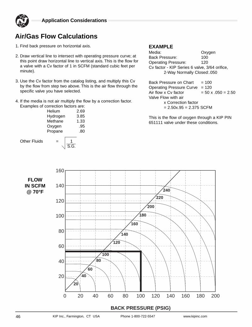
46 KIP Inc., Farmington, CT USA Phone 1-800-722-5547 www.kipinc.com
Application Considerations
Air/Gas Flow Calculations1. Find back pressure on horizontal axis.
2. Draw vertical line to intersect with operating pressure curve; atthis point draw horizontal line to vertical axis. This is the flow fora valve with a Cv factor of 1 in SCFM (standard cubic feet perminute).
3. Use the Cv factor from the catalog listing, and multiply this Cvby the flow from step two above. This is the air flow through thespecific valve you have selected.
4. If the media is not air multiply the flow by a correction factor.Examples of correction factors are:
Helium 2.69Hydrogen 3.85Methane 1.33Oxygen .95Propane .80
Other Fluids = 1S.G.
0
20
40
60
80
100
120
140
160
20
20
40
60
80100
120
140
160
180
200
220
240
40 60 80 100
BACK PRESSURE (PSIG)
120 140 160 180 200
FLOWIN SCFM@ 70°F
EXAMPLEMedia: OxygenBack Pressure: 100Operating Pressure: 120Cv factor - KIP Series 6 valve, 3/64 orifice,
2-Way Normally Closed:.050
Back Pressure on Chart = 100Operating Pressure Curve = 120Air flow x Cv factor = 50 x .050 = 2.50Valve Flow with air
x Correction factor = 2.50x.95 = 2.375 SCFM
This is the flow of oxygen through a KIP PIN651111 valve under these conditions.
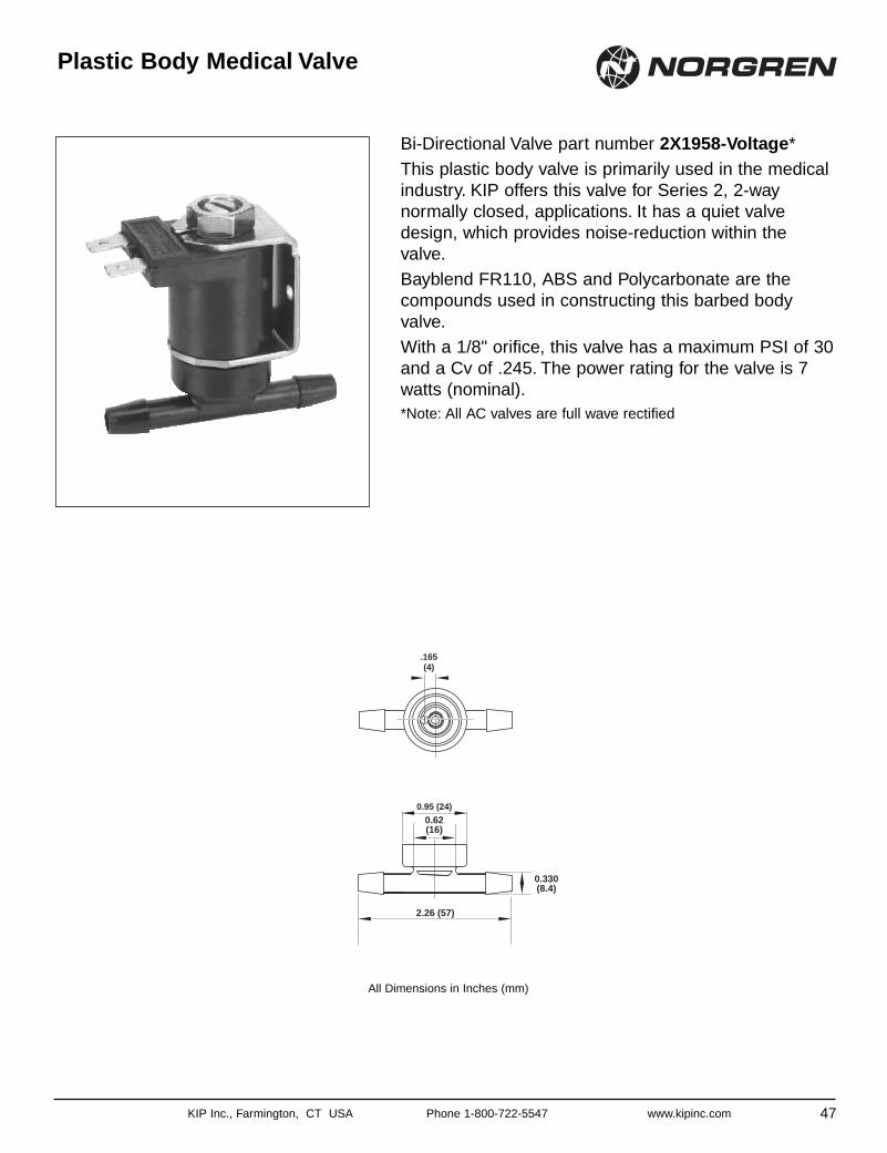
KIP Inc., Farmington, CT USA Phone 1-800-722-5547 www.kipinc.com
Bi-Directional Valve part number 2X1958-Voltage*This plastic body valve is primarily used in the medicalindustry. KIP offers this valve for Series 2, 2-waynormally closed, applications. It has a quiet valvedesign, which provides noise-reduction within thevalve.Bayblend FR110, ABS and Polycarbonate are thecompounds used in constructing this barbed bodyvalve.With a 1/8" orifice, this valve has a maximum PSI of 30and a Cv of .245. The power rating for the valve is 7watts (nominal).*Note: All AC valves are full wave rectified
Plastic Body Medical Valve
47
.165(4)
0.95 (24)
0.62(16)
2.26 (57)
0.330(8.4)
All Dimensions in Inches (mm)
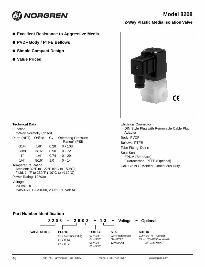
48 KIP Inc., Farmington, CT USA Phone 1-800-722-5547 www.kipinc.com
Model 8208
● Excellent Resistance to Aggressive Media
● PVDF Body / PTFE Bellows
● Simple Compact Design
● Value Priced
2-Way Plastic Media Isolation Valve
Technical DataFunction:
2-Way Normally ClosedPorts (NPT) Orifice Cv Operating Pressure
Range* (PSI)G1/4 1/8" 0.28 0 - 100G3/8 3/16" 0.50 0 - 72
1" 1/4" 0.74 0 - 291/4" 5/16" 1.0 0 - 14
Temperature RatingAmbient: 32°F to 122°F (0°C to +50°C)Fluid: 14°F to 230°F (-10°C to +110°C)
Power Rating: 12 Watt
Voltage:24 Volt DC24/50-60, 120/50-60, 230/50-60 Volt AC
Electrical Connector:DIN Style Plug with Removable Cable PlugAdapter
Body: PVDF
Bellows: PTFE
Tube Fitting: Delrin
Seat Seal:EPDM (Standard)Fluorocarbon, PTFE (Optional)
Coil: Class F, Molded, Continuous Duty
ORIFICE02 = 1/8"04 = 3/16"05 = 1/4"06 = 5/16"
PORTS95 = 1/4" Tube Fitting
25 = G 1/4
27 = G 3/8
Part Number Identification
8 2 0 8
SEAL02 = Fluorocarbon08 = PTFE 13 = EPDM
SUFFIXCO = 1/2" NPT ConduitCL = 1/2" NPT Conduit with
24" Lead Wires
VALVE SERIES
Voltage Optional2 5 0 2 1 3– – – –
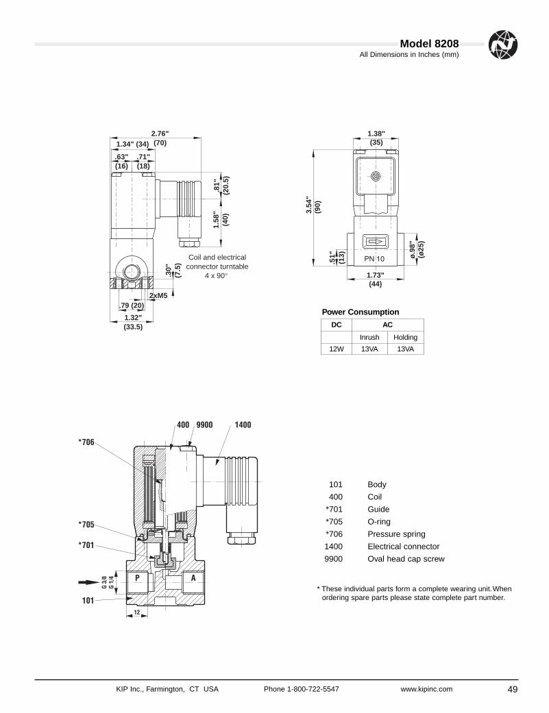
49
All Dimensions in Inches (mm)
KIP Inc., Farmington, CT USA Phone 1-800-722-5547 www.kipinc.com
Model 8208
1.38"(35)
3.54
"(9
0)
.51"
(13)
1.73"(44)
ø.9
8"(ø
25)
2.76"(70)
.63"(16)
.71"(18)
1.34" (34)
.30"
(7.5
)
1.32"(33.5)
.79 (20)2xM5
1.58
"(4
0).8
1"(2
0.5)
Coil and electricalconnector turntable
4 x 90°
101 Body
400 Coil
*701 Guide
*705 O-ring
*706 Pressure spring
1400 Electrical connector
9900 Oval head cap screw
* These individual parts form a complete wearing unit.Whenordering spare parts please state complete part number.
DC AC
Inrush Holding
12W 13VA 13VA
Power Consumption
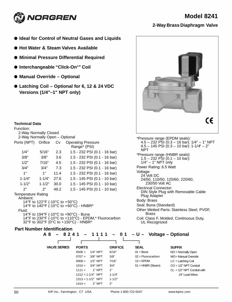
50 KIP Inc., Farmington, CT USA Phone 1-800-722-5547 www.kipinc.com
Model 8241
● Ideal for Control of Neutral Gases and Liquids
● Hot Water & Steam Valves Available
● Minimal Pressure Differential Required
● Interchangeable “Click-On®” Coil
● Manual Override – Optional
● Latching Coil – Optional for 6, 12 & 24 VDCVersions (1/4"–1" NPT only)
2-Way Brass Diaphragm Valve
Technical DataFunction:
2-Way Normally Closed2-Way Normally Open – Optional
Ports (NPT) Orifice Cv Operating PressureRange* (PSI)
1/4" 5/16" 2.3 1.5 - 232 PSI (0.1 - 16 bar)3/8" 3/8" 3.6 1.5 - 232 PSI (0.1 - 16 bar)1/2" 7/16" 4.5 1.5 - 232 PSI (0.1 - 16 bar)3/4" 3/4" 7.3 1.5 - 232 PSI (0.1 - 16 bar)1" 1" 11.4 1.5 - 232 PSI (0.1 - 16 bar)
1-1/4" 1-1/4" 27.6 1.5 - 145 PSI (0.1 - 10 bar)1-1/2" 1-1/2" 30.0 1.5 - 145 PSI (0.1 - 10 bar)
2" 2" 49.2 1.5 - 145 PSI (0.1 - 10 bar)Temperature Rating
Ambient:14°F to 122°F (-10°C to +50°C)14°F to 140°F (-10°C to +60°C) - HNBR*
Fluid:14°F to 194°F (-10°C to +90°C) - Buna14°F to 230°F (-10°C to +110°C) - EPDM,* Fluorocarbon32°F to 302°F (0°C to +150°C) - HNBR*
*Pressure range (EPDM seals):4.5 – 232 PSI (0.3 – 16 bar): 1/4" – 1" NPT4.5 – 145 PSI (0.3 – 10 bar): 1-1/4" – 2"NPT
*Pressure range (HNBR seals):1.5 – 232 PSI (0.1 – 10 bar):1/4" – 1" NPT only
Power Rating: 6.5 Watt Voltage:
24 Volt DC24/50, 110/50, 120/60, 220/60,
230/50 Volt ACElectrical Connector:
DIN Style Plug with Removable Cable Plug Adapter
Body: Brass Seal: Buna (Standard) Other Wetted Parts: Stainless Steel, PVDF,
Brass Coil: Class F, Molded, Continuous Duty,
UL Recognized
ORIFICE5/16"
3/8"
7/16"
3/4"
1"
1-1/4"
1-1/2"
2"
PORTS0506 = 1/4" NPT
0707 = 3/8" NPT
0908 = 1/2" NPT
1010 = 3/4" NPT
1111 = 1" NPT
1212 = 1-1/4" NPT
1313 = 1-1/2" NPT
1414 = 2" NPT
SEAL01 = Buna
02 = Fluorocarbon
13 = EPDM
51 = HNBR (Steam)
SUFFIXNO = Normally Open
MO= Manual Override
LC = Latching Coil
CO = 1/2" NPT Conduit
CL = 1/2" NPT Conduit with
24" Lead Wires
VALVE SERIES
A 8 – 8 2 4 1 – 1 1 1 1 – 0 1 – U – Voltage – OptionalPart Number Identification
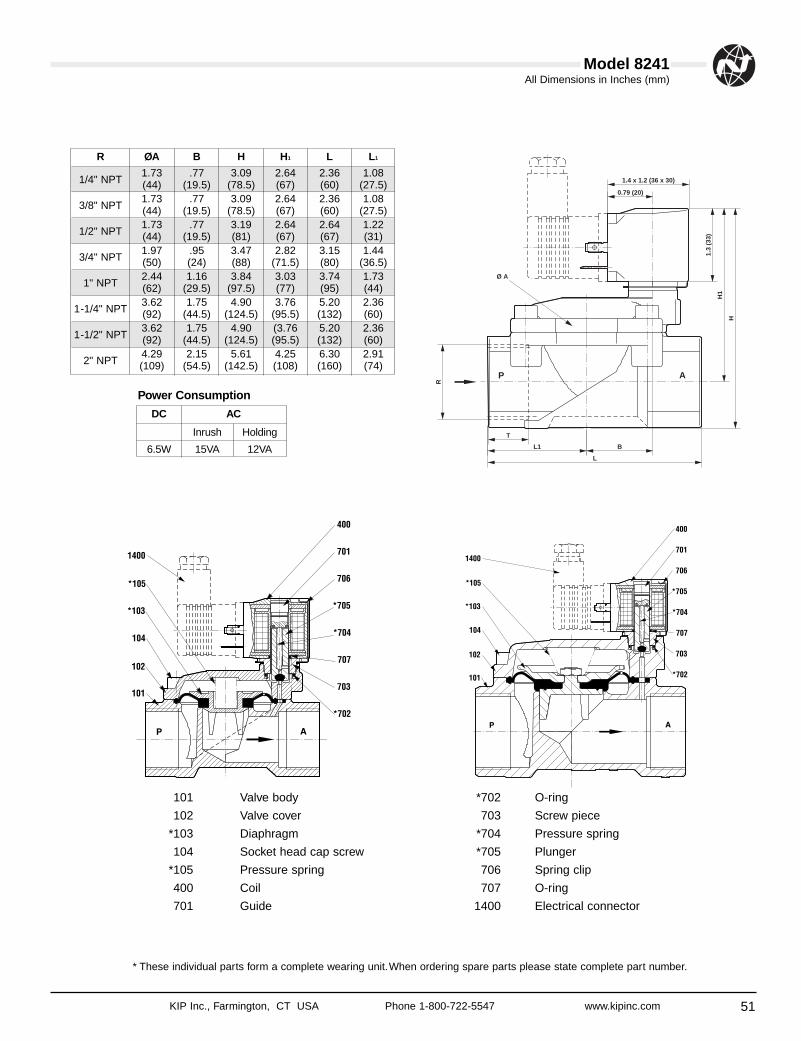
51
All Dimensions in Inches (mm)
KIP Inc., Farmington, CT USA Phone 1-800-722-5547 www.kipinc.com
Model 8241
R ØA B H H1 L L1
1/4" NPT1.73 .77 3.09 2.64 2.36 1.08(44) (19.5) (78.5) (67) (60) (27.5)
3/8" NPT1.73 .77 3.09 2.64 2.36 1.08(44) (19.5) (78.5) (67) (60) (27.5)
1/2" NPT1.73 .77 3.19 2.64 2.64 1.22(44) (19.5) (81) (67) (67) (31)
3/4" NPT1.97 .95 3.47 2.82 3.15 1.44(50) (24) (88) (71.5) (80) (36.5)
1" NPT2.44 1.16 3.84 3.03 3.74 1.73(62) (29.5) (97.5) (77) (95) (44)
1-1/4" NPT3.62 1.75 4.90 3.76 5.20 2.36(92) (44.5) (124.5) (95.5) (132) (60)
1-1/2" NPT3.62 1.75 4.90 (3.76 5.20 2.36(92) (44.5) (124.5) (95.5) (132) (60)
2" NPT4.29 2.15 5.61 4.25 6.30 2.91(109) (54.5) (142.5) (108) (160) (74)
101 Valve body
102 Valve cover
*103 Diaphragm
104 Socket head cap screw
*105 Pressure spring
400 Coil
701 Guide
*702 O-ring
703 Screw piece
*704 Pressure spring
*705 Plunger
706 Spring clip
707 O-ring
1400 Electrical connector
* These individual parts form a complete wearing unit.When ordering spare parts please state complete part number.
DC AC
Inrush Holding
6.5W 15VA 12VA
Power Consumption
T
BL1
L
1.4 x 1.2 (36 x 30)
0.79 (20)
R
H
H1
1.3
(33)
P A
Ø A
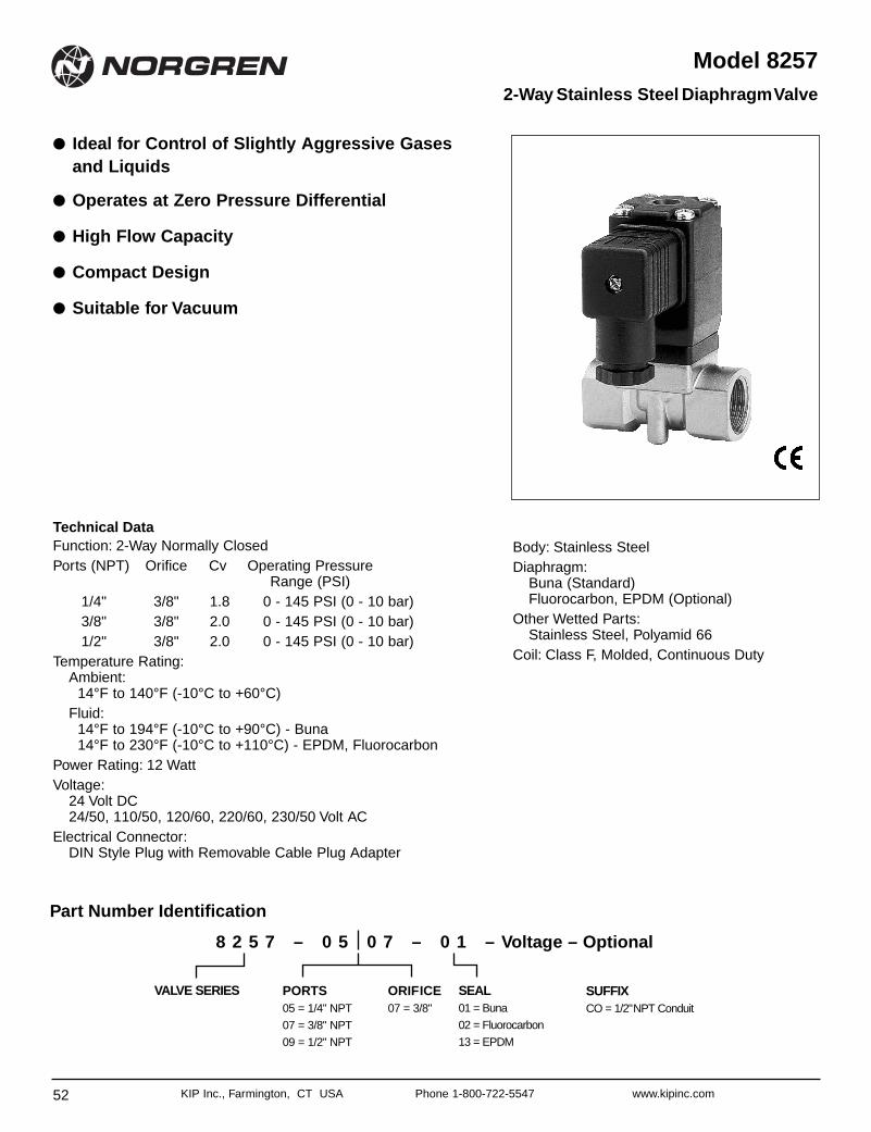
52 KIP Inc., Farmington, CT USA Phone 1-800-722-5547 www.kipinc.com
Model 8257
● Ideal for Control of Slightly Aggressive Gasesand Liquids
● Operates at Zero Pressure Differential
● High Flow Capacity
● Compact Design
● Suitable for Vacuum
2-Way Stainless Steel DiaphragmValve
Technical DataFunction: 2-Way Normally ClosedPorts (NPT) Orifice Cv Operating Pressure
Range (PSI)1/4" 3/8" 1.8 0 - 145 PSI (0 - 10 bar)3/8" 3/8" 2.0 0 - 145 PSI (0 - 10 bar)1/2" 3/8" 2.0 0 - 145 PSI (0 - 10 bar)
Temperature Rating:Ambient:
14°F to 140°F (-10°C to +60°C)Fluid:
14°F to 194°F (-10°C to +90°C) - Buna 14°F to 230°F (-10°C to +110°C) - EPDM, Fluorocarbon
Power Rating: 12 Watt Voltage:
24 Volt DC24/50, 110/50, 120/60, 220/60, 230/50 Volt AC
Electrical Connector:DIN Style Plug with Removable Cable Plug Adapter
Body: Stainless SteelDiaphragm:
Buna (Standard)Fluorocarbon, EPDM (Optional)
Other Wetted Parts:Stainless Steel, Polyamid 66
Coil: Class F, Molded, Continuous Duty
ORIFICE07 = 3/8"
PORTS05 = 1/4" NPT
07 = 3/8" NPT
09 = 1/2" NPT
SEAL01 = Buna
02 = Fluorocarbon
13 = EPDM
SUFFIXCO = 1/2"NPT Conduit
VALVE SERIES
8 2 5 7 – 0 5 0 7 – 0 1 – Voltage – Optional
Part Number Identification
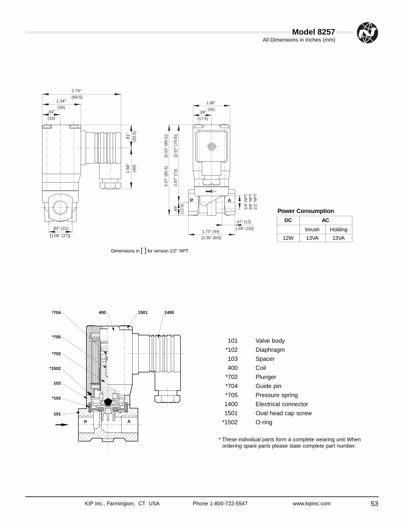
53
All Dimensions in Inches (mm)
KIP Inc., Farmington, CT USA Phone 1-800-722-5547 www.kipinc.com
Model 8257
.69"
(17.5)
1.38"
(35)
1/4"
NP
T3/
8" N
PT
1/2"
NP
T
[2.9
7" (
75.5
)]2.
87"
(73)
3.37
" (8
5.5)
[3.5
2" (
89.5
)]
.49"
(12.
5)
.47" (12)
[.59" (15)]1.73" (44)
[2.36" (60)]
P A
.83" (21)
1.58
"
(40)
.81"
(20.
5)
.63"
(16)
1.34"
(34)
2.74"
(69.5)
[1.06" (27)]
103
*702
*705
*704
*102
101
14001501400
*1502
P A
101 Valve body
*102 Diaphragm
103 Spacer
400 Coil
*702 Plunger
*704 Guide pin
*705 Pressure spring
1400 Electrical connector
1501 Oval head cap screw
*1502 O-ring
* These individual parts form a complete wearing unit.Whenordering spare parts please state complete part number.
Dimensions in [ ] for version 1/2" NPT.
DC AC
Inrush Holding
12W 13VA 13VA
Power Consumption
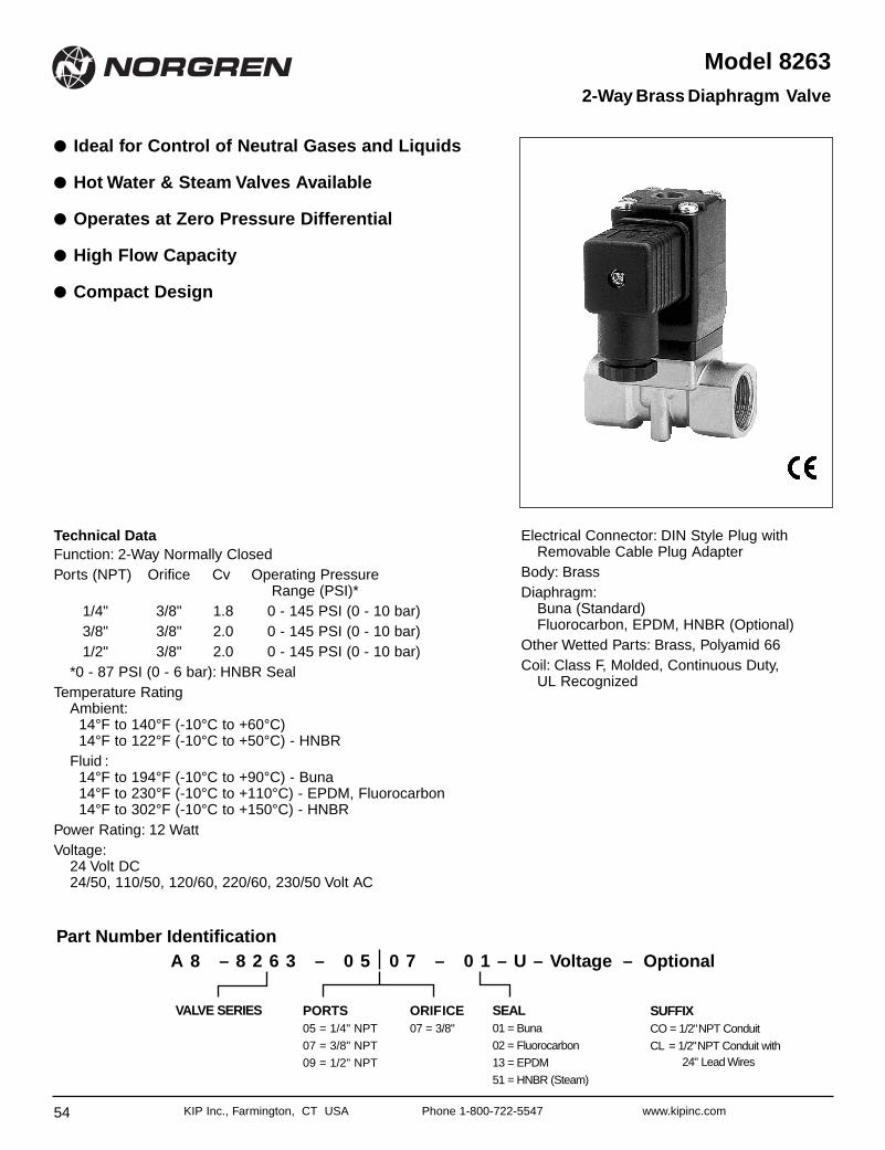
54 KIP Inc., Farmington, CT USA Phone 1-800-722-5547 www.kipinc.com
Model 8263
● Ideal for Control of Neutral Gases and Liquids
● Hot Water & Steam Valves Available
● Operates at Zero Pressure Differential
● High Flow Capacity
● Compact Design
2-Way Brass Diaphragm Valve
Technical DataFunction: 2-Way Normally ClosedPorts (NPT) Orifice Cv Operating Pressure
Range (PSI)*1/4" 3/8" 1.8 0 - 145 PSI (0 - 10 bar)3/8" 3/8" 2.0 0 - 145 PSI (0 - 10 bar)1/2" 3/8" 2.0 0 - 145 PSI (0 - 10 bar)
*0 - 87 PSI (0 - 6 bar): HNBR SealTemperature Rating
Ambient:14°F to 140°F (-10°C to +60°C) 14°F to 122°F (-10°C to +50°C) - HNBR
Fluid :14°F to 194°F (-10°C to +90°C) - Buna 14°F to 230°F (-10°C to +110°C) - EPDM, Fluorocarbon14°F to 302°F (-10°C to +150°C) - HNBR
Power Rating: 12 Watt Voltage:
24 Volt DC24/50, 110/50, 120/60, 220/60, 230/50 Volt AC
Electrical Connector: DIN Style Plug withRemovable Cable Plug Adapter
Body: BrassDiaphragm:
Buna (Standard)Fluorocarbon, EPDM, HNBR (Optional)
Other Wetted Parts: Brass, Polyamid 66Coil: Class F, Molded, Continuous Duty,
UL Recognized
Part Number Identification
ORIFICE07 = 3/8"
PORTS05 = 1/4" NPT
07 = 3/8" NPT
09 = 1/2" NPT
SEAL01 = Buna
02 = Fluorocarbon
13 = EPDM
51 = HNBR (Steam)
SUFFIXCO = 1/2"NPT Conduit
CL = 1/2"NPT Conduit with24" Lead Wires
VALVE SERIES
A 8 – 8 2 6 3 – 0 5 0 7 – 0 1 – U – Voltage – Optional
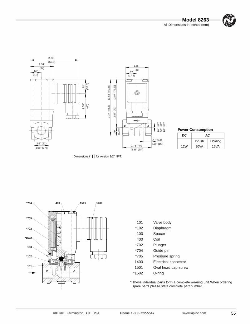
55
All Dimensions in Inches (mm)
KIP Inc., Farmington, CT USA Phone 1-800-722-5547 www.kipinc.com
Model 8263
.69"
(17.5)
1.38"
(35)
1/4"
NP
T3/
8" N
PT
1/2"
NP
T
[2.9
7" (
75.5
)]2.
87"
(73)
3.37
" (8
5.5)
[3.5
2" (
89.5
)]
.49"
(12.
5)
.47" (12)
[.59" (15)]1.73" (44)
[2.36" (60)]
P A
.83" (21)
1.58
"
(40)
.81"
(20.
5)
.63"
(16)
1.34"
(34)
2.74"
(69.5)
[1.06" (27)]
103
*702
*705
*704
*102
101
14001501400
*1502
P A
101 Valve body
*102 Diaphragm
103 Spacer
400 Coil
*702 Plunger
*704 Guide pin
*705 Pressure spring
1400 Electrical connector
1501 Oval head cap screw
*1502 O-ring
* These individual parts form a complete wearing unit.When orderingspare parts please state complete part number.
Dimensions in [ ] for version 1/2" NPT.
DC AC
Inrush Holding
12W 20VA 16VA
Power Consumption
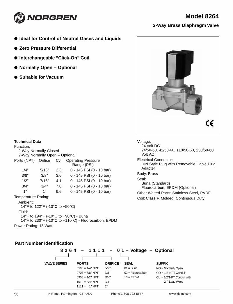
56 KIP Inc., Farmington, CT USA Phone 1-800-722-5547 www.kipinc.com
Model 8264
● Ideal for Control of Neutral Gases and Liquids
● Zero Pressure Differential
● Interchangeable “Click-On” Coil
● Normally Open – Optional
● Suitable for Vacuum
2-Way Brass Diaphragm Valve
Technical DataFunction:
2-Way Normally Closed2-Way Normally Open – Optional
Ports (NPT) Orifice Cv Operating PressureRange (PSI)
1/4" 5/16" 2.3 0 - 145 PSI (0 - 10 bar)3/8" 3/8" 3.6 0 - 145 PSI (0 - 10 bar)1/2" 7/16" 4.1 0 - 145 PSI (0 - 10 bar)3/4" 3/4" 7.0 0 - 145 PSI (0 - 10 bar)1" 1" 9.6 0 - 145 PSI (0 - 10 bar)
Temperature Rating:Ambient:
14°F to 122°F (-10°C to +50°C)Fluid:
14°F to 194°F (-10°C to +90°C) - Buna14°F to 230°F (-10°C to +110°C) - Fluorocarbon, EPDM
Power Rating: 18 Watt
Voltage:24 Volt DC24/50-60, 42/50-60, 110/50-60, 230/50-60Volt AC
Electrical Connector:DIN Style Plug with Removable Cable PlugAdapter
Body: Brass Seal:
Buna (Standard)Fluorocarbon, EPDM (Optional)
Other Wetted Parts: Stainless Steel, PVDFCoil: Class F, Molded, Continuous Duty
ORIFICE5/16"
3/8"
7/16"
3/4"
1"
PORTS0506 = 1/4" NPT
0707 = 3/8" NPT
0908 = 1/2" NPT
1010 = 3/4" NPT
1111 = 1" NPT
SEAL01 = Buna
02 = Fluorocarbon
13 = EPDM
SUFFIXNO = Normally Open
CO = 1/2"NPT Conduit
CL = 1/2"NPT Conduit with24" Lead Wires
VALVE SERIES
8 2 6 4 – 1 1 1 1 – 0 1 – Voltage – Optional
Part Number Identification
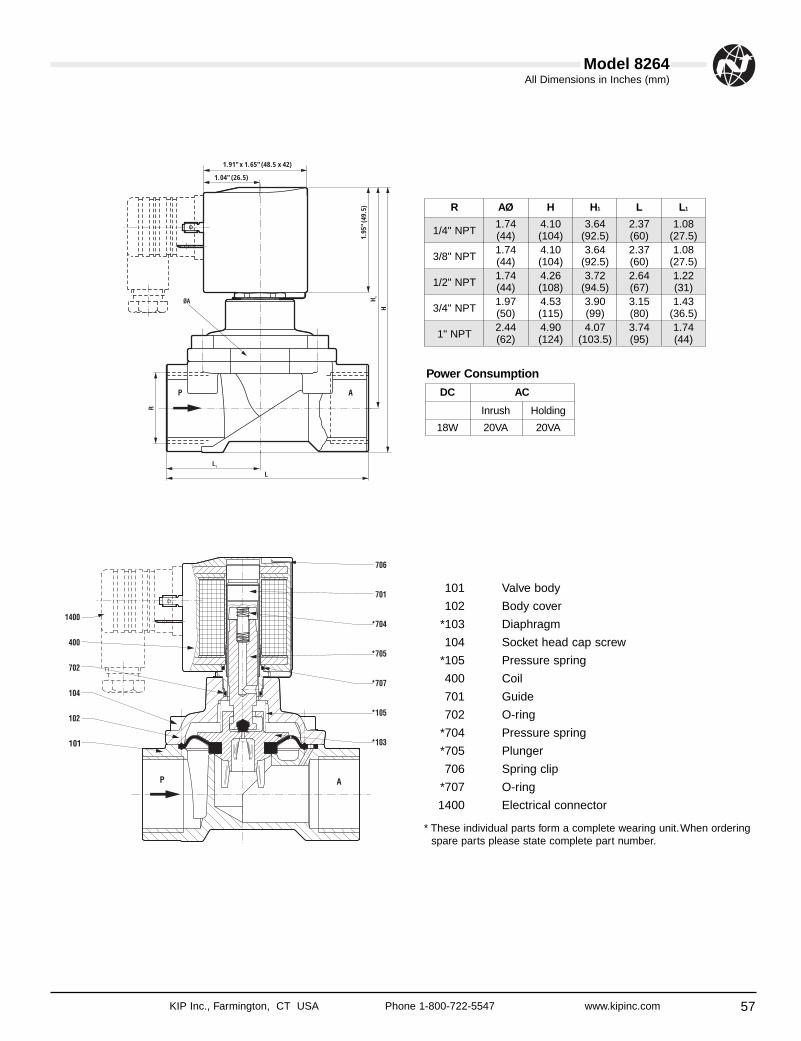
57
All Dimensions in Inches (mm)
KIP Inc., Farmington, CT USA Phone 1-800-722-5547 www.kipinc.com
Model 8264
1.91" x 1.65" (48.5 x 42)
1.04" (26.5)
1.95
" (49
.5)
101 Valve body
102 Body cover
*103 Diaphragm
104 Socket head cap screw
*105 Pressure spring
400 Coil
701 Guide
702 O-ring
*704 Pressure spring
*705 Plunger
706 Spring clip
*707 O-ring
1400 Electrical connector
* These individual parts form a complete wearing unit.When orderingspare parts please state complete part number.
R AØ H H1 L L1
1/4" NPT1.74 4.10 3.64 2.37 1.08(44) (104) (92.5) (60) (27.5)
3/8" NPT1.74 4.10 3.64 2.37 1.08(44) (104) (92.5) (60) (27.5)
1/2" NPT1.74 4.26 3.72 2.64 1.22(44) (108) (94.5) (67) (31)
3/4" NPT1.97 4.53 3.90 3.15 1.43(50) (115) (99) (80) (36.5)
1" NPT2.44 4.90 4.07 3.74 1.74(62) (124) (103.5) (95) (44)
DC AC
Inrush Holding
18W 20VA 20VA
Power Consumption
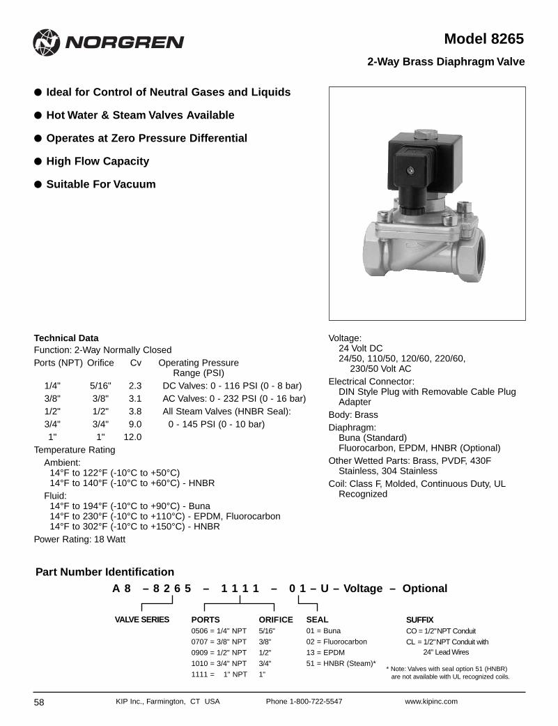
58 KIP Inc., Farmington, CT USA Phone 1-800-722-5547 www.kipinc.com
Model 8265
● Ideal for Control of Neutral Gases and Liquids
● Hot Water & Steam Valves Available
● Operates at Zero Pressure Differential
● High Flow Capacity
● Suitable For Vacuum
2-Way Brass Diaphragm Valve
Technical DataFunction: 2-Way Normally ClosedPorts (NPT) Orifice Cv Operating Pressure
Range (PSI)1/4" 5/16" 2.3 DC Valves: 0 - 116 PSI (0 - 8 bar)3/8" 3/8" 3.1 AC Valves: 0 - 232 PSI (0 - 16 bar)1/2" 1/2" 3.8 All Steam Valves (HNBR Seal):3/4" 3/4" 9.0 0 - 145 PSI (0 - 10 bar)1" 1" 12.0
Temperature RatingAmbient:
14°F to 122°F (-10°C to +50°C)14°F to 140°F (-10°C to +60°C) - HNBR
Fluid:14°F to 194°F (-10°C to +90°C) - Buna14°F to 230°F (-10°C to +110°C) - EPDM, Fluorocarbon14°F to 302°F (-10°C to +150°C) - HNBR
Power Rating: 18 Watt
Voltage:24 Volt DC24/50, 110/50, 120/60, 220/60,
230/50 Volt ACElectrical Connector:
DIN Style Plug with Removable Cable PlugAdapter
Body: Brass Diaphragm:
Buna (Standard)Fluorocarbon, EPDM, HNBR (Optional)
Other Wetted Parts: Brass, PVDF, 430FStainless, 304 Stainless
Coil: Class F, Molded, Continuous Duty, ULRecognized
* Note: Valves with seal option 51 (HNBR) are not available with UL recognized coils.
ORIFICE5/16"
3/8"
1/2"
3/4"
1"
PORTS0506 = 1/4" NPT
0707 = 3/8" NPT
0909 = 1/2" NPT
1010 = 3/4" NPT
1111 = 1" NPT
SEAL01 = Buna
02 = Fluorocarbon
13 = EPDM
51 = HNBR (Steam)*
SUFFIXCO = 1/2"NPT Conduit
CL = 1/2"NPT Conduit with24" Lead Wires
VALVE SERIES
A 8 – 8 2 6 5 – 1 1 1 1 – 0 1 – U – Voltage – OptionalPart Number Identification
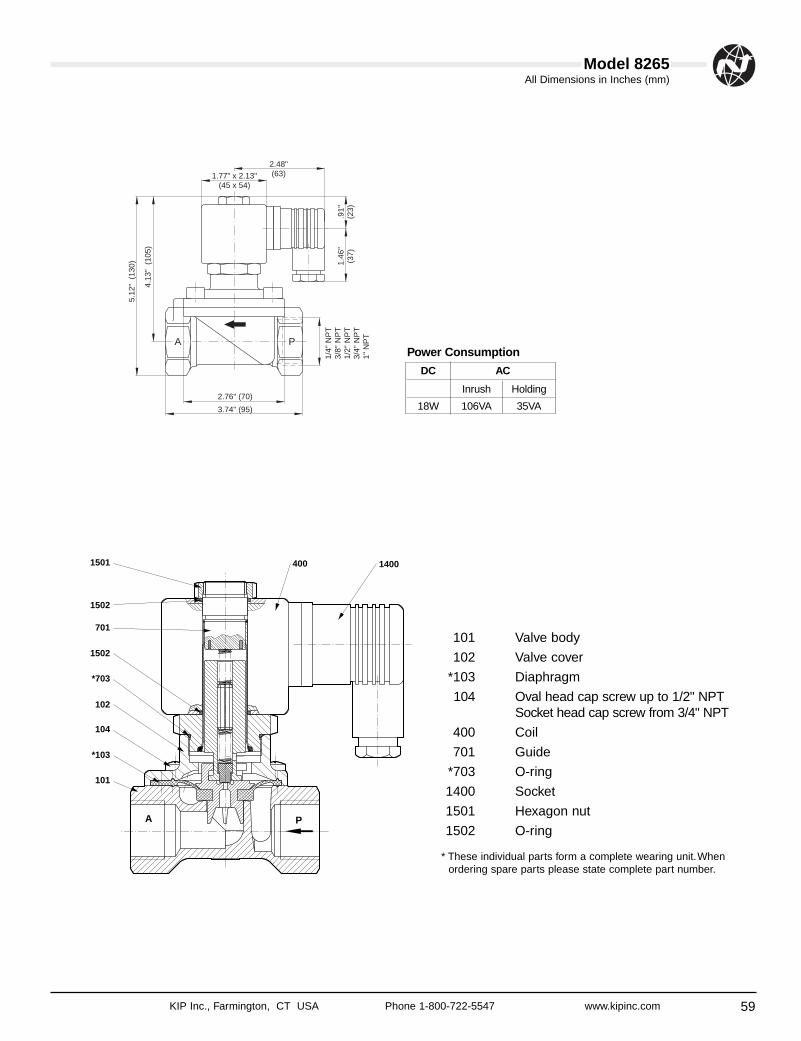
59
All Dimensions in Inches (mm)
KIP Inc., Farmington, CT USA Phone 1-800-722-5547 www.kipinc.com
Model 8265
A P
5.12
" (
130)
4.13
" (
105)
1.77" x 2.13"(45 x 54)
2.48"(63)
2.76" (70)
3.74" (95)
3/4"
NP
T1"
NP
T
1/4"
NP
T3/
8" N
PT
1/2"
NP
T1.
46"
(37)
.91"
(23)
A P
101
*103
104
102
701
*703
1502
1501
1502
1400400
101 Valve body
102 Valve cover
*103 Diaphragm
104 Oval head cap screw up to 1/2" NPTSocket head cap screw from 3/4" NPT
400 Coil
701 Guide
*703 O-ring
1400 Socket
1501 Hexagon nut
1502 O-ring
* These individual parts form a complete wearing unit.Whenordering spare parts please state complete part number.
DC AC
Inrush Holding
18W 106VA 35VA
Power Consumption
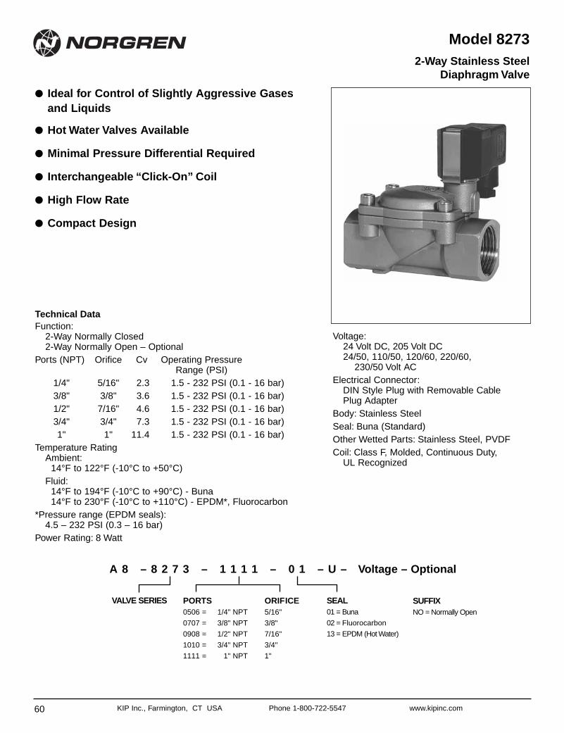
60 KIP Inc., Farmington, CT USA Phone 1-800-722-5547 www.kipinc.com
2-Way Stainless SteelDiaphragm Valve
Model 8273
● Ideal for Control of Slightly Aggressive Gasesand Liquids
● Hot Water Valves Available
● Minimal Pressure Differential Required
● Interchangeable “Click-On” Coil
● High Flow Rate
● Compact Design
Technical DataFunction:
2-Way Normally Closed2-Way Normally Open – Optional
Ports (NPT) Orifice Cv Operating PressureRange (PSI)
1/4" 5/16" 2.3 1.5 - 232 PSI (0.1 - 16 bar)3/8" 3/8" 3.6 1.5 - 232 PSI (0.1 - 16 bar)1/2" 7/16" 4.6 1.5 - 232 PSI (0.1 - 16 bar)3/4" 3/4" 7.3 1.5 - 232 PSI (0.1 - 16 bar)1" 1" 11.4 1.5 - 232 PSI (0.1 - 16 bar)
Temperature RatingAmbient:
14°F to 122°F (-10°C to +50°C)Fluid:
14°F to 194°F (-10°C to +90°C) - Buna14°F to 230°F (-10°C to +110°C) - EPDM*, Fluorocarbon
*Pressure range (EPDM seals):4.5 – 232 PSI (0.3 – 16 bar)
Power Rating: 8 Watt
Voltage:24 Volt DC, 205 Volt DC24/50, 110/50, 120/60, 220/60,
230/50 Volt ACElectrical Connector:
DIN Style Plug with Removable Cable Plug Adapter
Body: Stainless Steel Seal: Buna (Standard) Other Wetted Parts: Stainless Steel, PVDFCoil: Class F, Molded, Continuous Duty,
UL Recognized
ORIFICE5/16"
3/8"
7/16"
3/4"
1"
PORTS0506 = 1/4" NPT
0707 = 3/8" NPT
0908 = 1/2" NPT
1010 = 3/4" NPT
1111 = 1" NPT
SEAL01 = Buna
02 = Fluorocarbon
13 = EPDM (Hot Water)
SUFFIXNO = Normally Open
VALVE SERIES
A 8 – 8 2 7 3 – 1 1 1 1 – 0 1 – U – Voltage – Optional
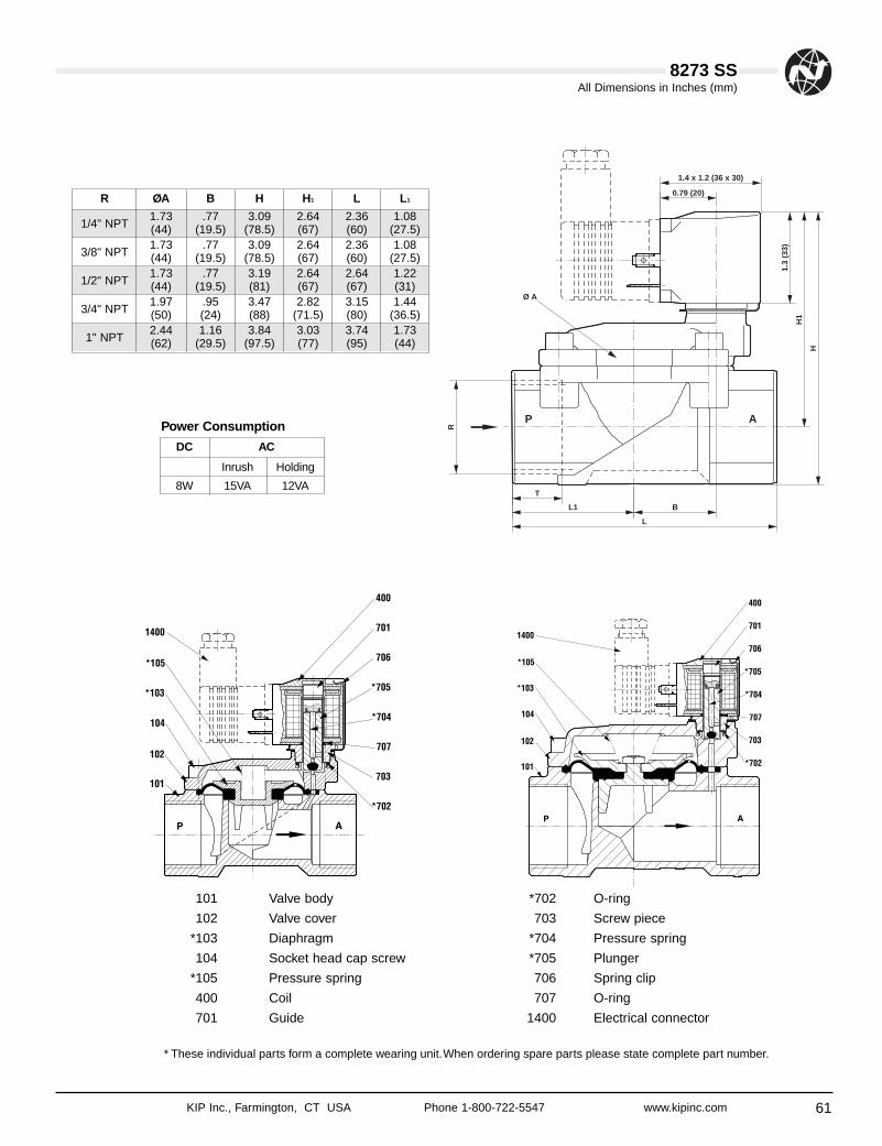
61
All Dimensions in Inches (mm)
KIP Inc., Farmington, CT USA Phone 1-800-722-5547 www.kipinc.com
8273 SS
R ØA B H H1 L L1
1/4" NPT1.73 .77 3.09 2.64 2.36 1.08(44) (19.5) (78.5) (67) (60) (27.5)
3/8" NPT1.73 .77 3.09 2.64 2.36 1.08(44) (19.5) (78.5) (67) (60) (27.5)
1/2" NPT1.73 .77 3.19 2.64 2.64 1.22(44) (19.5) (81) (67) (67) (31)
3/4" NPT1.97 .95 3.47 2.82 3.15 1.44(50) (24) (88) (71.5) (80) (36.5)
1" NPT2.44 1.16 3.84 3.03 3.74 1.73(62) (29.5) (97.5) (77) (95) (44)
101 Valve body
102 Valve cover
*103 Diaphragm
104 Socket head cap screw
*105 Pressure spring
400 Coil
701 Guide
*702 O-ring
703 Screw piece
*704 Pressure spring
*705 Plunger
706 Spring clip
707 O-ring
1400 Electrical connector
* These individual parts form a complete wearing unit.When ordering spare parts please state complete part number.
DC AC
Inrush Holding
8W 15VA 12VA
Power Consumption
T
BL1
L
1.4 x 1.2 (36 x 30)
0.79 (20)
R
H
H1
1.3
(33)
P A
Ø A
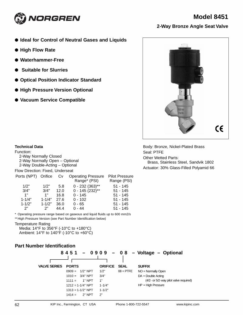
62 KIP Inc., Farmington, CT USA Phone 1-800-722-5547 www.kipinc.com
Model 8451
● Ideal for Control of Neutral Gases and Liquids
● High Flow Rate
● Waterhammer-Free
● Suitable for Slurries
● Optical Position Indicator Standard
● High Pressure Version Optional
● Vacuum Service Compatible
2-Way Bronze Angle Seat Valve
Technical DataFunction:
2-Way Normally Closed2-Way Normally Open – Optional2-Way Double-Acting – Optional
Flow Direction: Fixed, UnderseatPorts (NPT) Orifice Cv Operating Pressure Pilot Pressure
Range* (PSI) Range (PSI)1/2" 1/2" 5.8 0 - 232 (363)** 51 - 1453/4" 3/4" 12.0 0 - 145 (232)** 51 - 1451" 1" 16.8 0 - 145 51 - 145
1-1/4" 1-1/4" 27.6 0 - 102 51 - 1451-1/2" 1-1/2" 36.0 0 - 65 51 - 145
2" 2" 44.4 0 - 44 51 - 145* Operating pressure range based on gaseous and liquid fluids up to 600 mm2/s**High Pressure Version (see Part Number Identification below)
Temperature RatingMedia: 14°F to 356°F (-10°C to +180°C)Ambient: 14°F to 140°F (-10°C to +60°C)
Body: Bronze, Nickel-Plated BrassSeal: PTFEOther Wetted Parts:
Brass, Stainless Steel, Sandvik 1802Actuator: 30% Glass-Filled Polyamid 66
ORIFICE1/2"
3/4"
1"
1-1/4"
1-1/2"
2"
PORTS0909 = 1/2" NPT
1010 = 3/4" NPT
1111 = 1" NPT
1212 = 1-1/4" NPT
1313 = 1-1/2" NPT
1414 = 2" NPT
SEAL08 = PTFE
SUFFIXNO = Normally Open
DA = Double Acting(4/2- or 5/2-way pilot valve required)
HP = High Pressure
VALVE SERIES
8 4 5 1 – 0 9 0 9 – 0 8 – Voltage – OptionalPart Number Identification
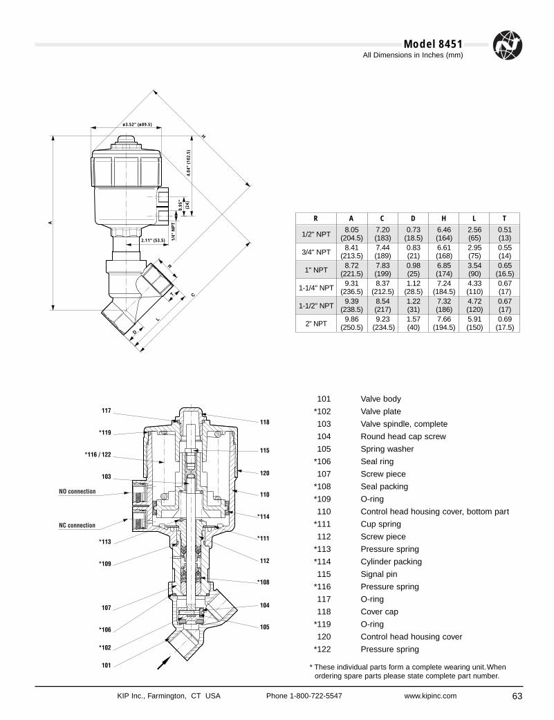
63
All Dimensions in Inches (mm)
KIP Inc., Farmington, CT USA Phone 1-800-722-5547 www.kipinc.com
Model 8451
ø3.52" (ø89.5)
2.11" (53.5)
4.04
" (1
02.5
)
0.95
"
(24)
101 Valve body
*102 Valve plate
103 Valve spindle, complete
104 Round head cap screw
105 Spring washer
*106 Seal ring
107 Screw piece
*108 Seal packing
*109 O-ring
110 Control head housing cover, bottom part
*111 Cup spring
112 Screw piece
*113 Pressure spring
*114 Cylinder packing
115 Signal pin
*116 Pressure spring
117 O-ring
118 Cover cap
*119 O-ring
120 Control head housing cover
*122 Pressure spring
* These individual parts form a complete wearing unit.Whenordering spare parts please state complete part number.
R A C D H L T
1/2" NPT8.05 7.20 0.73 6.46 2.56 0.51
(204.5) (183) (18.5) (164) (65) (13)
3/4" NPT8.41 7.44 0.83 6.61 2.95 0.55
(213.5) (189) (21) (168) (75) (14)
1" NPT8.72 7.83 0.98 6.85 3.54 0.65
(221.5) (199) (25) (174) (90) (16.5)
1-1/4" NPT9.31 8.37 1.12 7.24 4.33 0.67
(236.5) (212.5) (28.5) (184.5) (110) (17)
1-1/2" NPT9.39 8.54 1.22 7.32 4.72 0.67
(238.5) (217) (31) (186) (120) (17)
2" NPT9.86 9.23 1.57 7.66 5.91 0.69
(250.5) (234.5) (40) (194.5) (150) (17.5)
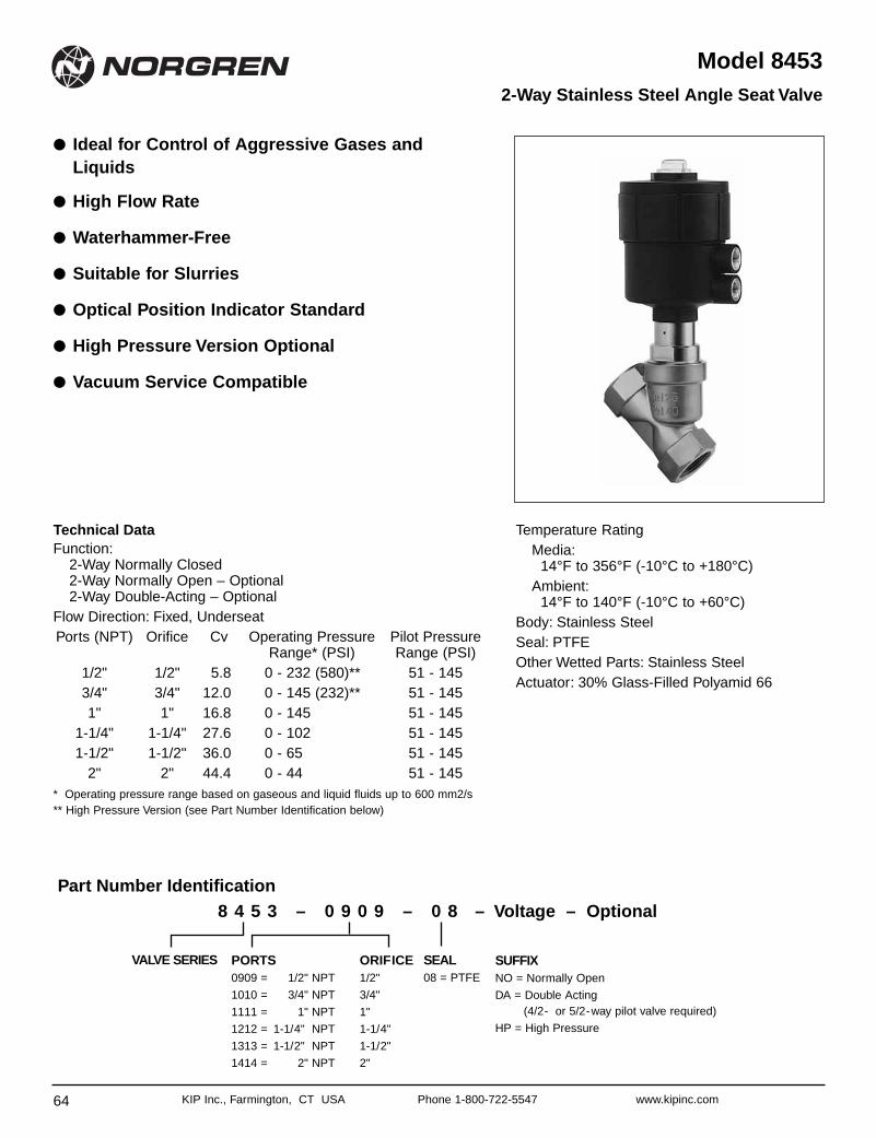
64 KIP Inc., Farmington, CT USA Phone 1-800-722-5547 www.kipinc.com
Model 8453
● Ideal for Control of Aggressive Gases andLiquids
● High Flow Rate
● Waterhammer-Free
● Suitable for Slurries
● Optical Position Indicator Standard
● High Pressure Version Optional
● Vacuum Service Compatible
2-Way Stainless Steel Angle Seat Valve
Technical DataFunction:
2-Way Normally Closed2-Way Normally Open – Optional2-Way Double-Acting – Optional
Flow Direction: Fixed, UnderseatPorts (NPT) Orifice Cv Operating Pressure Pilot Pressure
Range* (PSI) Range (PSI)1/2" 1/2" 5.8 0 - 232 (580)** 51 - 1453/4" 3/4" 12.0 0 - 145 (232)** 51 - 1451" 1" 16.8 0 - 145 51 - 145
1-1/4" 1-1/4" 27.6 0 - 102 51 - 1451-1/2" 1-1/2" 36.0 0 - 65 51 - 145
2" 2" 44.4 0 - 44 51 - 145* Operating pressure range based on gaseous and liquid fluids up to 600 mm2/s** High Pressure Version (see Part Number Identification below)
Temperature RatingMedia:
14°F to 356°F (-10°C to +180°C)Ambient:
14°F to 140°F (-10°C to +60°C)Body: Stainless SteelSeal: PTFEOther Wetted Parts: Stainless SteelActuator: 30% Glass-Filled Polyamid 66
ORIFICE1/2"
3/4"
1"
1-1/4"
1-1/2"
2"
PORTS0909 = 1/2" NPT
1010 = 3/4" NPT
1111 = 1" NPT
1212 = 1-1/4" NPT
1313 = 1-1/2" NPT
1414 = 2" NPT
SEAL08 = PTFE
SUFFIXNO = Normally Open
DA = Double Acting(4/2- or 5/2-way pilot valve required)
HP = High Pressure
VALVE SERIES
8 4 5 3 – 0 9 0 9 – 0 8 – Voltage – OptionalPart Number Identification
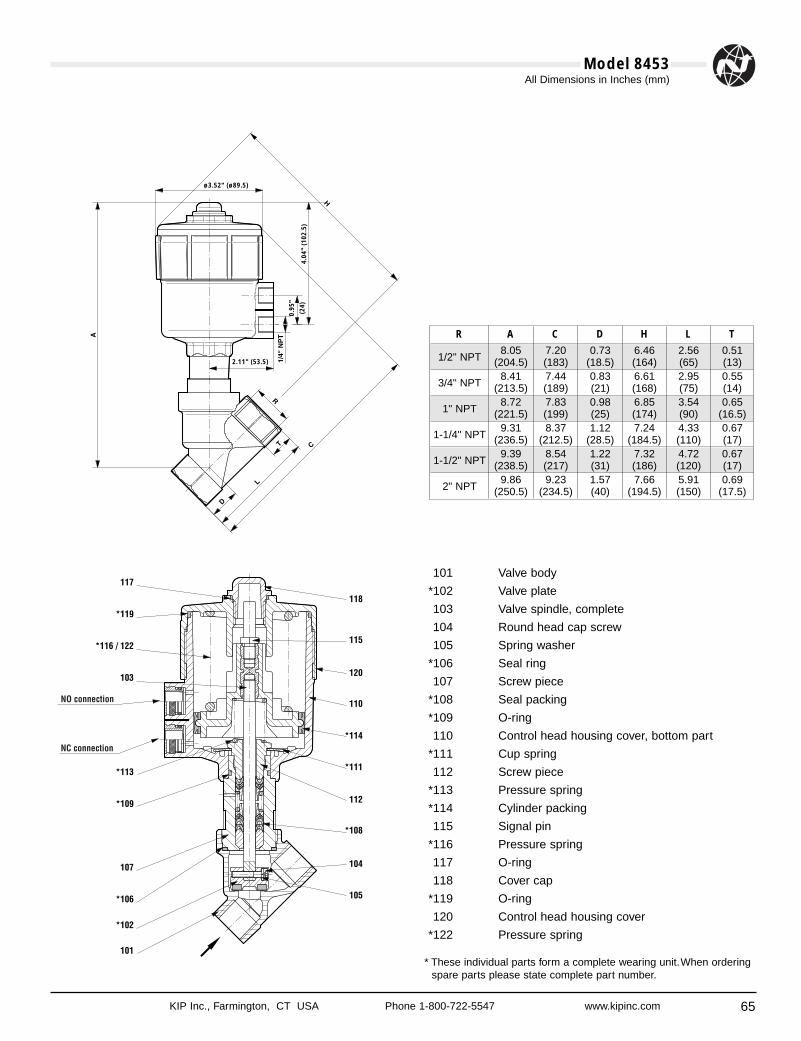
65
All Dimensions in Inches (mm)
KIP Inc., Farmington, CT USA Phone 1-800-722-5547 www.kipinc.com
Model 8453
101 Valve body
*102 Valve plate
103 Valve spindle, complete
104 Round head cap screw
105 Spring washer
*106 Seal ring
107 Screw piece
*108 Seal packing
*109 O-ring
110 Control head housing cover, bottom part
*111 Cup spring
112 Screw piece
*113 Pressure spring
*114 Cylinder packing
115 Signal pin
*116 Pressure spring
117 O-ring
118 Cover cap
*119 O-ring
120 Control head housing cover
*122 Pressure spring
* These individual parts form a complete wearing unit.When orderingspare parts please state complete part number.
ø3.52" (ø89.5)
2.11" (53.5)
4.04
" (1
02.5
)
0.95
"
(24)
R A C D H L T
1/2" NPT8.05 7.20 0.73 6.46 2.56 0.51
(204.5) (183) (18.5) (164) (65) (13)
3/4" NPT8.41 7.44 0.83 6.61 2.95 0.55
(213.5) (189) (21) (168) (75) (14)
1" NPT8.72 7.83 0.98 6.85 3.54 0.65
(221.5) (199) (25) (174) (90) (16.5)
1-1/4" NPT9.31 8.37 1.12 7.24 4.33 0.67
(236.5) (212.5) (28.5) (184.5) (110) (17)
1-1/2" NPT9.39 8.54 1.22 7.32 4.72 0.67
(238.5) (217) (31) (186) (120) (17)
2" NPT9.86 9.23 1.57 7.66 5.91 0.69
(250.5) (234.5) (40) (194.5) (150) (17.5)
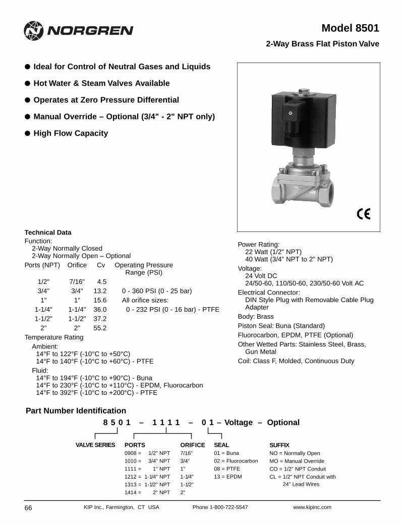
66 KIP Inc., Farmington, CT USA Phone 1-800-722-5547 www.kipinc.com
Model 8501
● Ideal for Control of Neutral Gases and Liquids
● Hot Water & Steam Valves Available
● Operates at Zero Pressure Differential
● Manual Override – Optional (3/4" - 2" NPT only)
● High Flow Capacity
2-Way Brass Flat Piston Valve
Technical DataFunction:
2-Way Normally Closed2-Way Normally Open – Optional
Ports (NPT) Orifice Cv Operating PressureRange (PSI)
1/2" 7/16" 4.53/4" 3/4" 13.2 0 - 360 PSI (0 - 25 bar)1" 1" 15.6 All orifice sizes:
1-1/4" 1-1/4" 36.0 0 - 232 PSI (0 - 16 bar) - PTFE1-1/2" 1-1/2" 37.2
2" 2" 55.2Temperature Rating
Ambient:14°F to 122°F (-10°C to +50°C)14°F to 140°F (-10°C to +60°C) - PTFE
Fluid:14°F to 194°F (-10°C to +90°C) - Buna14°F to 230°F (-10°C to +110°C) - EPDM, Fluorocarbon14°F to 392°F (-10°C to +200°C) - PTFE
Power Rating:22 Watt (1/2" NPT)40 Watt (3/4" NPT to 2" NPT)
Voltage:24 Volt DC24/50-60, 110/50-60, 230/50-60 Volt AC
Electrical Connector:DIN Style Plug with Removable Cable PlugAdapter
Body: Brass Piston Seal: Buna (Standard) Fluorocarbon, EPDM, PTFE (Optional)Other Wetted Parts: Stainless Steel, Brass,
Gun MetalCoil: Class F, Molded, Continuous Duty
ORIFICE7/16"
3/4"
1"
1-1/4"
1-1/2"
2"
PORTS0908 = 1/2" NPT
1010 = 3/4" NPT
1111 = 1" NPT
1212 = 1-1/4" NPT
1313 = 1-1/2" NPT
1414 = 2" NPT
SEAL01 = Buna
02 = Fluorocarbon
08 = PTFE
13 = EPDM
SUFFIXNO = Normally Open
MO = Manual Override
CO = 1/2" NPT Conduit
CL = 1/2" NPT Conduit with 24" Lead Wires
VALVE SERIES
8 5 0 1 – 1 1 1 1 – 0 1 – Voltage – OptionalPart Number Identification
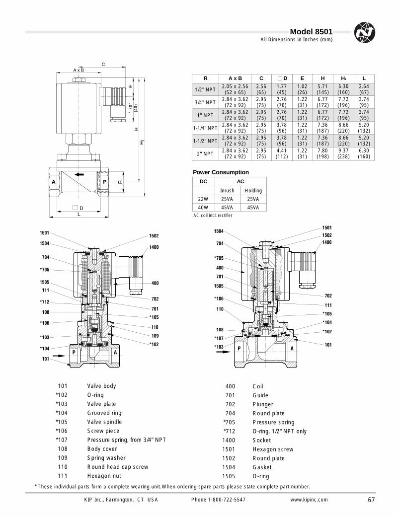
67
All Dimensions in Inches (mm)
KIP Inc., Farmington, CT USA Phone 1-800-722-5547 www.kipinc.com
Model 8501
1.58
"(4
0)
101 Valve body
*102 O-ring
*103 Valve plate
*104 Grooved ring
*105 Valve spindle
*106 Screw piece
*107 Pressure spring, from 3/4" NPT
108 Body cover
109 Spring washer
110 Round head cap screw
111 Hexagon nut
400 Coil
701 Guide
702 Plunger
704 Round plate
*705 Pressure spring
*712 O-ring, 1/2" NPT only
1400 Socket
1501 Hexagon screw
1502 Round plate
1504 Gasket
1505 O-ring
* These individual parts form a complete wearing unit.When ordering spare parts please state complete part number.
AC coil incl. rectifier
DC AC
Inrush Holding
22W 25VA 25VA
40W 45VA 45VA
Power Consumption
R A x B C ■■ D E H H1 L
1/2" NPT2.05 x 2.56 2.56 1.77 1.02 5.71 6.30 2.64(52 x 65) (65) (45) (26) (145) (160) (67)
3/4" NPT2.84 x 3.62 2.95 2.76 1.22 6.77 7.72 3.74(72 x 92) (75) (70) (31) (172) (196) (95)
1" NPT2.84 x 3.62 2.95 2.76 1.22 6.77 7.72 3.74(72 x 92) (75) (70) (31) (172) (196) (95)
1-1/4" NPT2.84 x 3.62 2.95 3.78 1.22 7.36 8.66 5.20(72 x 92) (75) (96) (31) (187) (220) (132)
1-1/2" NPT2.84 x 3.62 2.95 3.78 1.22 7.36 8.66 5.20(72 x 92) (75) (96) (31) (187) (220) (132)
2" NPT2.84 x 3.62 2.95 4.41 1.22 7.80 9.37 6.30(72 x 92) (75) (112) (31) (198) (238) (160)
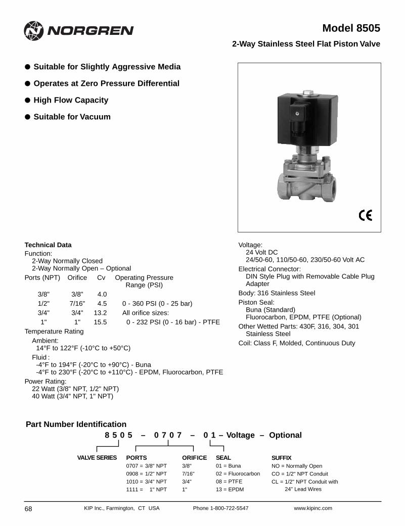
68 KIP Inc., Farmington, CT USA Phone 1-800-722-5547 www.kipinc.com
Model 8505
● Suitable for Slightly Aggressive Media
● Operates at Zero Pressure Differential
● High Flow Capacity
● Suitable for Vacuum
2-Way Stainless Steel Flat Piston Valve
Technical DataFunction:
2-Way Normally Closed2-Way Normally Open – Optional
Ports (NPT) Orifice Cv Operating PressureRange (PSI)
3/8" 3/8" 4.01/2" 7/16" 4.5 0 - 360 PSI (0 - 25 bar)3/4" 3/4" 13.2 All orifice sizes:1" 1" 15.5 0 - 232 PSI (0 - 16 bar) - PTFE
Temperature RatingAmbient:
14°F to 122°F (-10°C to +50°C)Fluid :
-4°F to 194°F (-20°C to +90°C) - Buna-4°F to 230°F (-20°C to +110°C) - EPDM, Fluorocarbon, PTFE
Power Rating:22 Watt (3/8" NPT, 1/2" NPT) 40 Watt (3/4" NPT, 1" NPT)
Voltage:24 Volt DC24/50-60, 110/50-60, 230/50-60 Volt AC
Electrical Connector:DIN Style Plug with Removable Cable PlugAdapter
Body: 316 Stainless Steel Piston Seal:
Buna (Standard)Fluorocarbon, EPDM, PTFE (Optional)
Other Wetted Parts: 430F, 316, 304, 301Stainless Steel
Coil: Class F, Molded, Continuous Duty
ORIFICE3/8"
7/16"
3/4"
1"
PORTS0707 = 3/8" NPT
0908 = 1/2" NPT
1010 = 3/4" NPT
1111 = 1" NPT
SEAL01 = Buna
02 = Fluorocarbon
08 = PTFE
13 = EPDM
SUFFIXNO = Normally Open
CO = 1/2" NPT Conduit
CL = 1/2" NPT Conduit with24" Lead Wires
VALVE SERIES
8 5 0 5 – 0 7 0 7 – 0 1 – Voltage – OptionalPart Number Identification
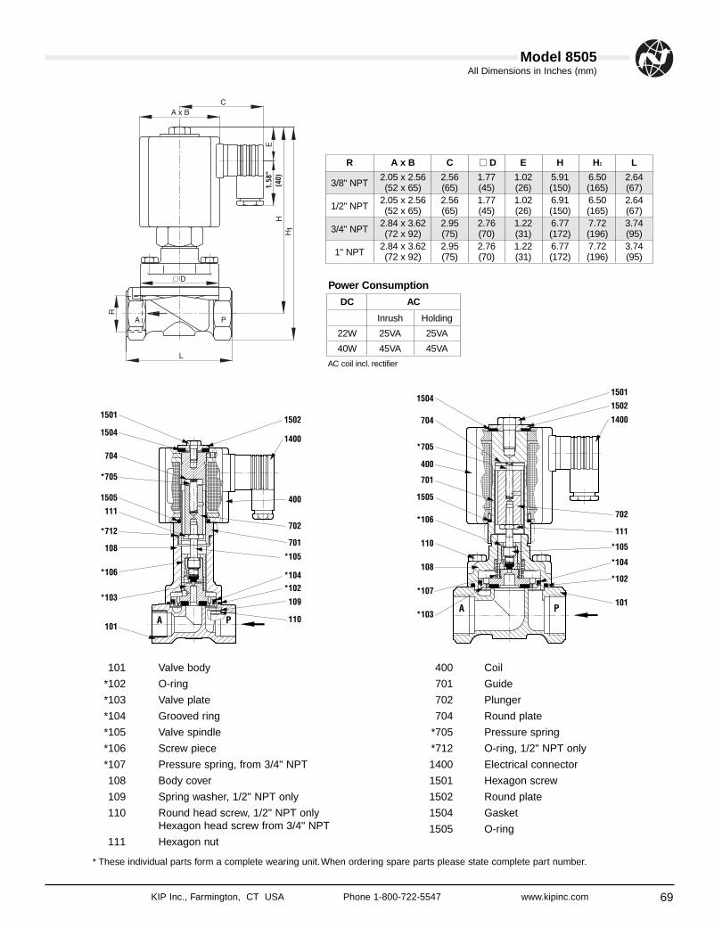
69
All Dimensions in Inches (mm)
KIP Inc., Farmington, CT USA Phone 1-800-722-5547 www.kipinc.com
Model 8505
101 Valve body
*102 O-ring
*103 Valve plate
*104 Grooved ring
*105 Valve spindle
*106 Screw piece
*107 Pressure spring, from 3/4" NPT
108 Body cover
109 Spring washer, 1/2" NPT only
110 Round head screw, 1/2" NPT onlyHexagon head screw from 3/4" NPT
111 Hexagon nut
400 Coil
701 Guide
702 Plunger
704 Round plate
*705 Pressure spring
*712 O-ring, 1/2" NPT only
1400 Electrical connector
1501 Hexagon screw
1502 Round plate
1504 Gasket
1505 O-ring
* These individual parts form a complete wearing unit.When ordering spare parts please state complete part number.
1.58
"(4
0)
AC coil incl. rectifier
DC AC
Inrush Holding
22W 25VA 25VA
40W 45VA 45VA
Power Consumption
R A x B C ■■ D E H H1 L
3/8" NPT2.05 x 2.56 2.56 1.77 1.02 5.91 6.50 2.64(52 x 65) (65) (45) (26) (150) (165) (67)
1/2" NPT2.05 x 2.56 2.56 1.77 1.02 6.91 6.50 2.64(52 x 65) (65) (45) (26) (150) (165) (67)
3/4" NPT2.84 x 3.62 2.95 2.76 1.22 6.77 7.72 3.74(72 x 92) (75) (70) (31) (172) (196) (95)
1" NPT2.84 x 3.62 2.95 2.76 1.22 6.77 7.72 3.74(72 x 92) (75) (70) (31) (172) (196) (95)
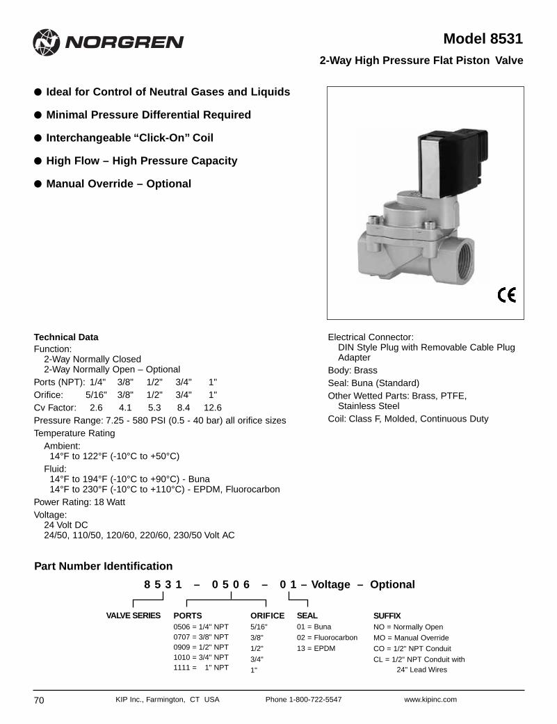
70 KIP Inc., Farmington, CT USA Phone 1-800-722-5547 www.kipinc.com
Model 8531
● Ideal for Control of Neutral Gases and Liquids
● Minimal Pressure Differential Required
● Interchangeable “Click-On” Coil
● High Flow – High Pressure Capacity
● Manual Override – Optional
2-Way High Pressure Flat Piston Valve
Technical DataFunction:
2-Way Normally Closed2-Way Normally Open – Optional
Ports (NPT): 1/4" 3/8" 1/2" 3/4" 1"Orifice: 5/16" 3/8" 1/2" 3/4" 1"Cv Factor: 2.6 4.1 5.3 8.4 12.6Pressure Range: 7.25 - 580 PSI (0.5 - 40 bar) all orifice sizesTemperature Rating
Ambient:14°F to 122°F (-10°C to +50°C)
Fluid:14°F to 194°F (-10°C to +90°C) - Buna 14°F to 230°F (-10°C to +110°C) - EPDM, Fluorocarbon
Power Rating: 18 WattVoltage:
24 Volt DC24/50, 110/50, 120/60, 220/60, 230/50 Volt AC
Electrical Connector:DIN Style Plug with Removable Cable PlugAdapter
Body: BrassSeal: Buna (Standard)Other Wetted Parts: Brass, PTFE,
Stainless SteelCoil: Class F, Molded, Continuous Duty
ORIFICE5/16"
3/8"
1/2"
3/4"
1"
PORTS0506 = 1/4" NPT0707 = 3/8" NPT0909 = 1/2" NPT1010 = 3/4" NPT1111 = 1" NPT
SEAL01 = Buna
02 = Fluorocarbon
13 = EPDM
SUFFIXNO = Normally Open
MO = Manual Override
CO = 1/2" NPT Conduit
CL = 1/2" NPT Conduit with24" Lead Wires
VALVE SERIES
8 5 3 1 – 0 5 0 6 – 0 1 – Voltage – Optional
Part Number Identification
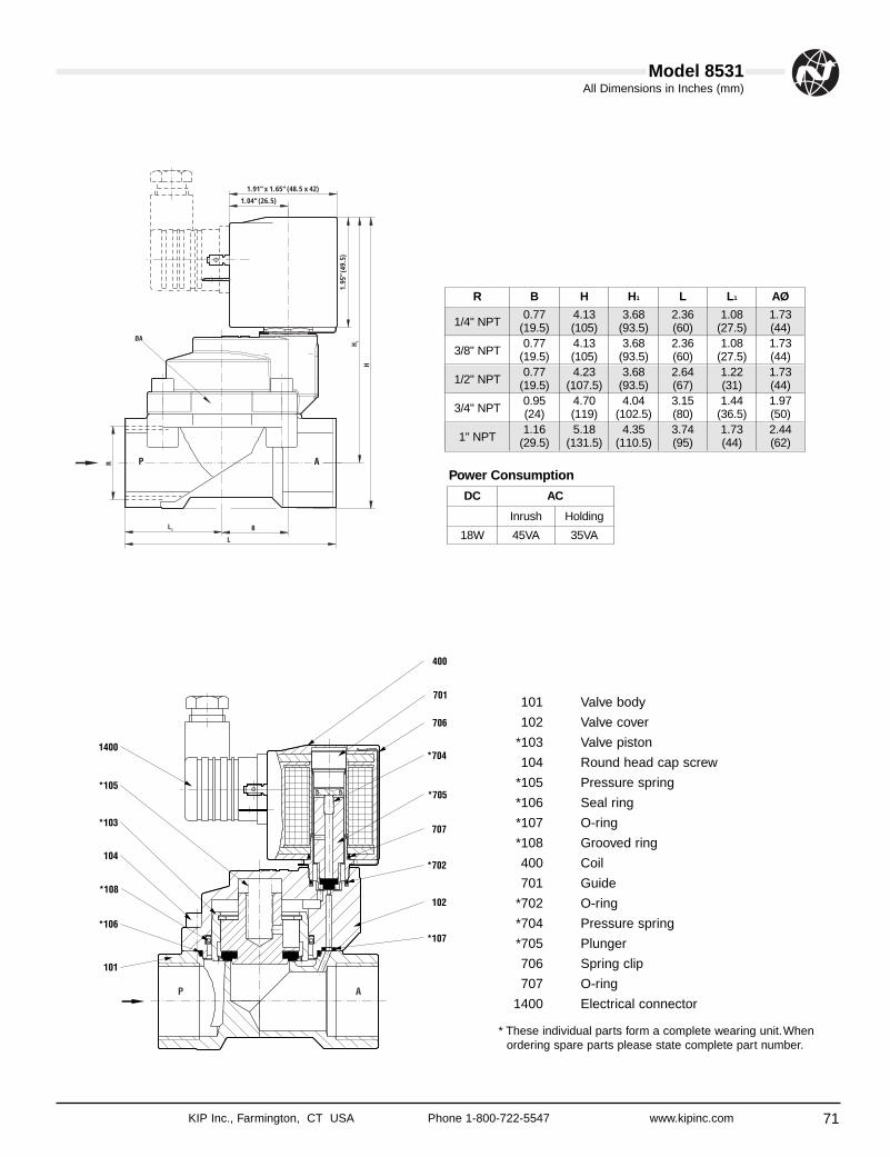
71
All Dimensions in Inches (mm)
KIP Inc., Farmington, CT USA Phone 1-800-722-5547 www.kipinc.com
Model 8531
1.91" x 1.65" (48.5 x 42)
1.04" (26.5)
1.95
" (49
.5)
101 Valve body
102 Valve cover
*103 Valve piston
104 Round head cap screw
*105 Pressure spring
*106 Seal ring
*107 O-ring
*108 Grooved ring
400 Coil
701 Guide
*702 O-ring
*704 Pressure spring
*705 Plunger
706 Spring clip
707 O-ring
1400 Electrical connector
* These individual parts form a complete wearing unit.Whenordering spare parts please state complete part number.
R B H H1 L L1 AØ
1/4" NPT0.77 4.13 3.68 2.36 1.08 1.73
(19.5) (105) (93.5) (60) (27.5) (44)
3/8" NPT0.77 4.13 3.68 2.36 1.08 1.73
(19.5) (105) (93.5) (60) (27.5) (44)
1/2" NPT0.77 4.23 3.68 2.64 1.22 1.73
(19.5) (107.5) (93.5) (67) (31) (44)
3/4" NPT0.95 4.70 4.04 3.15 1.44 1.97(24) (119) (102.5) (80) (36.5) (50)
1" NPT1.16 5.18 4.35 3.74 1.73 2.44
(29.5) (131.5) (110.5) (95) (44) (62)
DC AC
Inrush Holding
18W 45VA 35VA
Power Consumption
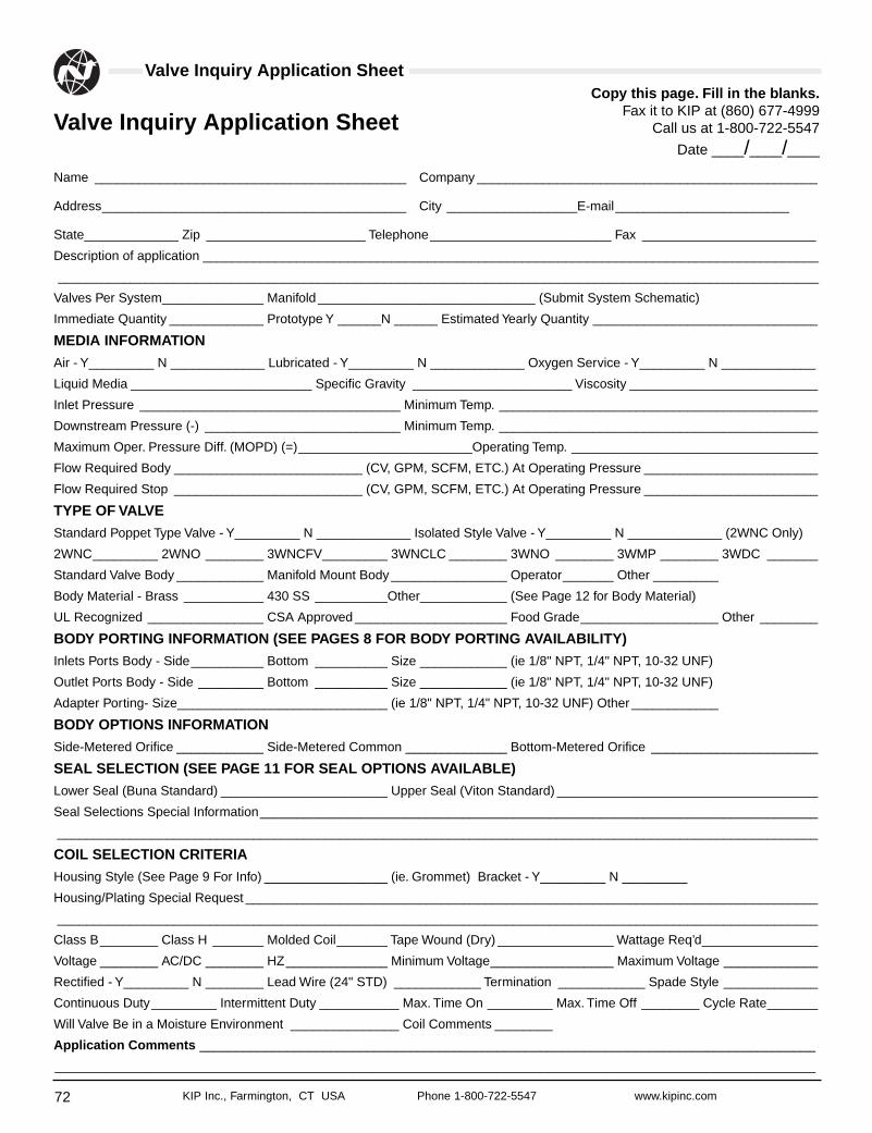
Single Point Levels
72 KIP Inc., Farmington, CT USA Phone 1-800-722-5547 www.kipinc.com
Single Point LevelsSingle Point LevelsValve Inquiry Application Sheet
Valve Inquiry Application Sheet
Name ___________________________________________ Company _______________________________________________
Address__________________________________________ City __________________E-mail________________________
State_____________ Zip ______________________ Telephone_________________________ Fax ________________________
Description of application _____________________________________________________________________________________
_________________________________________________________________________________________________________
Valves Per System______________ Manifold ______________________________ (Submit System Schematic)
Immediate Quantity _____________ Prototype Y ______N ______ Estimated Yearly Quantity _______________________________
MEDIA INFORMATION
Air - Y_________ N _____________ Lubricated - Y_________ N _____________ Oxygen Service - Y_________ N _____________
Liquid Media _________________________ Specific Gravity ______________________ Viscosity __________________________
Inlet Pressure ____________________________________ Minimum Temp. ____________________________________________
Downstream Pressure (-) ___________________________ Minimum Temp. ____________________________________________
Maximum Oper. Pressure Diff. (MOPD) (=)________________________Operating Temp. __________________________________
Flow Required Body __________________________ (CV, GPM, SCFM, ETC.) At Operating Pressure ________________________
Flow Required Stop __________________________ (CV, GPM, SCFM, ETC.) At Operating Pressure ________________________
TYPE OF VALVE
Standard Poppet Type Valve - Y_________ N _____________ Isolated Style Valve - Y_________ N _____________ (2WNC Only)
2WNC_________ 2WNO ________ 3WNCFV_________ 3WNCLC ________ 3WNO ________ 3WMP ________ 3WDC _______
Standard Valve Body ____________ Manifold Mount Body ________________ Operator_______ Other _________
Body Material - Brass ___________ 430 SS __________Other____________ (See Page 12 for Body Material)
UL Recognized ________________ CSA Approved _____________________ Food Grade___________________ Other ________
BODY PORTING INFORMATION (SEE PAGES 8 FOR BODY PORTING AVAILABILITY)
Inlets Ports Body - Side__________ Bottom __________ Size ____________ (ie 1/8" NPT, 1/4" NPT, 10-32 UNF)
Outlet Ports Body - Side _________ Bottom __________ Size ____________ (ie 1/8" NPT, 1/4" NPT, 10-32 UNF)
Adapter Porting- Size_____________________________ (ie 1/8" NPT, 1/4" NPT, 10-32 UNF) Other ____________
BODY OPTIONS INFORMATION
Side-Metered Orifice ____________ Side-Metered Common ______________ Bottom-Metered Orifice _______________________
SEAL SELECTION (SEE PAGE 11 FOR SEAL OPTIONS AVAILABLE)
Lower Seal (Buna Standard) _______________________ Upper Seal (Viton Standard) ____________________________________
Seal Selections Special Information_____________________________________________________________________________
_________________________________________________________________________________________________________
COIL SELECTION CRITERIA
Housing Style (See Page 9 For Info) _________________ (ie. Grommet) Bracket - Y_________ N _________
Housing/Plating Special Request _______________________________________________________________________________
_________________________________________________________________________________________________________
Class B________ Class H _______ Molded Coil_______ Tape Wound (Dry) ________________ Wattage Req’d________________
Voltage ________ AC/DC ________ HZ______________ Minimum Voltage_________________ Maximum Voltage _____________
Rectified - Y_________ N ________ Lead Wire (24" STD) ____________ Termination ____________ Spade Style _____________
Continuous Duty_________ Intermittent Duty ___________ Max. Time On _________ Max. Time Off ________ Cycle Rate_______
Will Valve Be in a Moisture Environment _______________ Coil Comments ________
Application Comments _____________________________________________________________________________________
_________________________________________________________________________________________________________
Copy this page. Fill in the blanks.Fax it to KIP at (860) 677-4999
Call us at 1-800-722-5547
Date ____/____/____
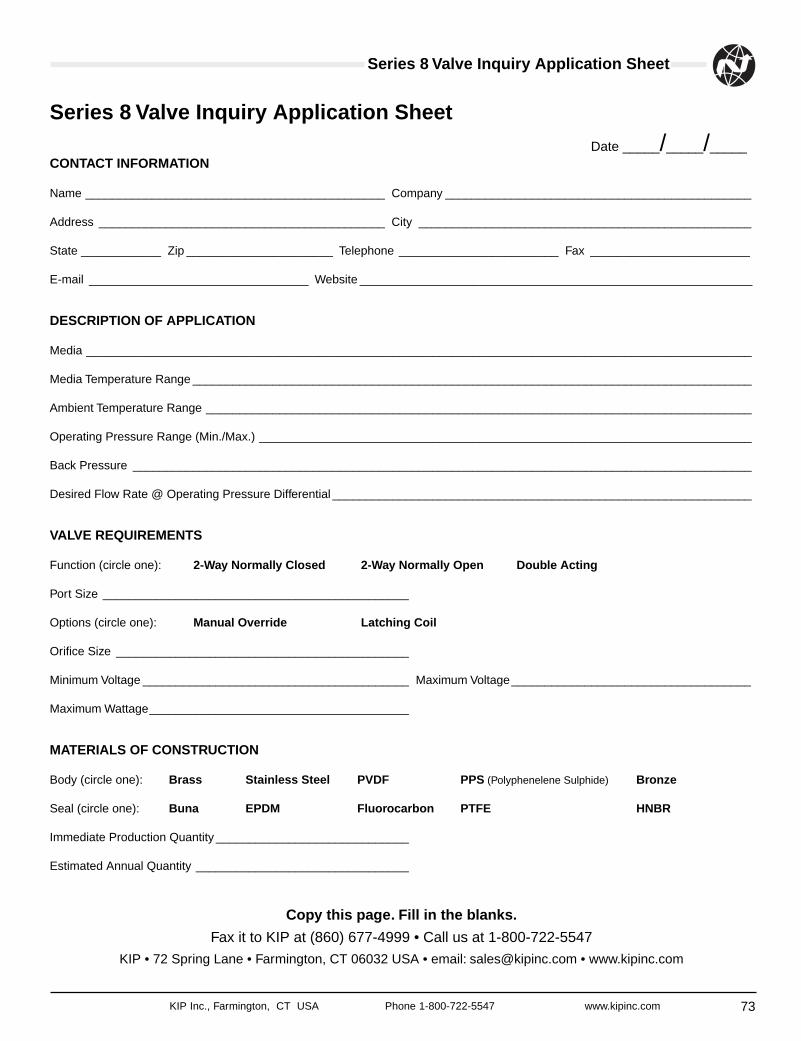
Series 8 Valve Inquiry Application Sheet
73KIP Inc., Farmington, CT USA Phone 1-800-722-5547 www.kipinc.com
Series 8 Valve Inquiry Application Sheet
CONTACT INFORMATION
Name _____________________________________________ Company ______________________________________________
Address ___________________________________________ City __________________________________________________
State ____________ Zip ______________________ Telephone ________________________ Fax ________________________
E-mail _________________________________ Website ___________________________________________________________
DESCRIPTION OF APPLICATION
Media ____________________________________________________________________________________________________
Media Temperature Range ____________________________________________________________________________________
Ambient Temperature Range __________________________________________________________________________________
Operating Pressure Range (Min./Max.) __________________________________________________________________________
Back Pressure _____________________________________________________________________________________________
Desired Flow Rate @ Operating Pressure Differential _______________________________________________________________
VALVE REQUIREMENTS
Function (circle one): 2-Way Normally Closed 2-Way Normally Open Double Acting
Port Size ______________________________________________
Options (circle one): Manual Override Latching Coil
Orifice Size ____________________________________________
Minimum Voltage ________________________________________ Maximum Voltage____________________________________
Maximum Wattage_______________________________________
MATERIALS OF CONSTRUCTION
Body (circle one): Brass Stainless Steel PVDF PPS (Polyphenelene Sulphide) Bronze
Seal (circle one): Buna EPDM Fluorocarbon PTFE HNBR
Immediate Production Quantity _____________________________
Estimated Annual Quantity ________________________________
Copy this page. Fill in the blanks.
Fax it to KIP at (860) 677-4999 • Call us at 1-800-722-5547
KIP • 72 Spring Lane • Farmington, CT 06032 USA • email: [email protected] • www.kipinc.com
Date _____/_____/_____
Warning/Warranty
74 KIP Inc., Farmington, CT USA Phone 1-800-722-5547 www.kipinc.com
Warning
These products are intended to use inindustrial compressed air systems only. Do notuse these products where pressures andtemperatures can exceed those listed underSpecifications.
Before using these products with fluids otherthan those specified, for non-industrialapplications, life-support systems, or otherapplications not within published specifications,consult Norgren.
Through misuse, age, or malfunction,components used in fluid power systems canfail in various modes. The system designer iswarned to consider the failure modes of allcomponent parts used in fluid power systemsand to provide adequate safeguards to preventpersonal injury or damage to equipment in theevent of such failure modes. System designersmust provide a warning to end users in thesystem instructional manual if protectionagainst a failure mode cannot be adequatelyprovided.
System designers and end users arecautioned to review specific warnings found ininstruction sheets packed and shipped withthese products. System designers should alsoprovide for all OSHA requirements including Title29 CFR 1910.147 Lockout/Tagout.
It should be recognized that warnings arevalid for any product, regardless ofmanufacturer, and are not restricted to productsmanufactured by Norgren. Norgren’s reputationfor product quality and performance is wellestablished. We feel we have the additionalobligation to provide information or warnings tocustomers to assist them in applying ourproducts in a reasonable and safe manner.
WarrantyLimited Warranty, Disclaimer and Limitationof Remedies
Items sold by Norgren are warranted to befree from defects in materials and workmanshipfor a period of one year from the datemanufacture, provided said items are usedaccording to Norgren’s recommended usagesand within Norgren’s specifications. Norgren’sliability is limited to the repair of, or replacementin kind of, at Norgren’s sole option, any itemsproved defective, provided these items arereturned to Norgren prepaid. To confirm date ofpurchase, invoice date or invoice number mustbe furnished; otherwise, date code on productwill be used to determine eligibility for warrantycoverage. The warranties expressed above arein lieu of and exclusive of all other warranties.
There are no other warranties, expressedor implied, except as stated herein. There areno implied warranties of merchantability orfitness for a particular purpose, which arespecifically disclaimed. Norgren’s liability forbreach of warranty as herein stated in theexclusive remedy, and in no event shallNorgren be liable or responsible forincidental or consequential damages, even ifthe possibility of such incidental orconsequential damages has been madeknown to Norgren.
Norgren reserves the right to discontinuemanufacture of any product or change productmaterials, design, or specifications withoutnotice.