Embed Size (px)
Citation preview

ROYAL s,YEDISH
GEOTECHNICAL INSTITUTE
PROCEEDINGS
No. 7
SOME SIDE-INTAKE
SOIL SAMPLERS FOR SAND
i-\ND GRAVEL
By
TORSTEN KALLSTENIUS
STOCKHOLM 1953


ROYAL S\VEDISH
GEOTECHNICAL INSTITUTE
PROCEEDI N GS
N o. 7
SOME SIDE-INTAKE
SOIL SAMPLERS FOR SAND
AND GRAVEL
By
TOR STEN KALLSTE N I U S
STOCKIIOLi\I 19 53

I var Hceggstroms
BOK'fll\"CKERI AB. STOCK II OLM 195 3 631593
Contents
Preface . . . . . . . . . . . . . . . . . . . . . . . . . . . . . . . . . . . . . . . . . . . . . . . . . . . . . . . . . . . . 5
§ I. General Considerations . . . . . . . . . . . . . . . . . . . . . . . . . . . . . . . . . . . . . . . . . . 7
§ 2. P enetration Ability of Samplers . . . . . . . . . . . . . . . . . . . . . . . . . . . . . . . . . . 7
§ 2 a. Pushing Rod Down in Loose Sand or Gravel . . . . . . . . . . . . . . . . . . 8
§ 2 b. Screwing Rod Down in Loose Sand or Gravcl . . . . . . . . . . . . . . . . . 9
§ 2 c. Ramming Rod Down in Loose Sand or Gravel . . . . . . . . . . . . . . . . 10
§ 2 d. Conditions in Dense Sand or Gravel . . . . . . . . . . . . . . . . . . . . . . . . . 11
§ 2 e. Conditions in Stony Sand or Gravel . . . . . . . . . . . . . . . . . . . . . . . . . 11
§ 2 f. Penetration Ability of Sampler Compared with That of Rod . . . . 11
§ 3. Sampler Withdrawn after Taking Each Sample . . . . . . . . . . . . . . . . . . . . J1
§ 3 a. Model I 12
§ 3 b. Model II 1-t
§ 4. Sampler, Part of which is Withdrawn after Taking Each Sample . . . . . . 14
§ 4 a. Model A 16
§ 4 b. J\Iodel B 16
§ 4 c. Model C 18
§ 5. Sampler Withdrawn Only Once after Sinking Each Bore Hole . . . . . . 20
§ 5 a. Wager's Sampler . . . . . . . . . . . . . . . . . . . . . . . . . . . . . . . . . . . . . . . . . . 20
§ 5 a I. Principle . . . . . . . . . . . . . . . . . . . . . . . . . . . . . . . . . . . . . . . . . 20
§ 5 a 2. Details . . . . . . . . . . . . . . . . . . . . . . . . . . . . . . . . . . . . . . . . . . . 20
§ 5 a 3. Evaluation of Samples . . . . . . . . . . . . . . . . . . . . . . . . . . . . . 22
§ 5 a 4. Additional Device . . . . . . . . . . . . . . . . . . . . . . . . . . . . . . . . . 24
§ 5 a 5. Sampler in Practice . . . . . . . . . . . . . . . . . . . . . . . . . . . . . . . . 24
3

§ 5 b. Kallstenius's Sampler . . . . . . . . . . . . . . . . . . . . . . . . . . . . . . . . . . . . . 24
§ 5 b 1. Principle . . . . . . . . . . . . . . . . . . . . . . . . . . . . . . . . . . . . . . . . . 24
§ 5 b 2. Details of Sampler Proper . . . . . . . . . . . . . . . . . . . . . . . . . . 28
§ 5 b 3. Handling . . . . . . . . . . . . . . . . . . . . . . . . . . . . . . . . . . . . . . . . . 31
§ 5 b 4. Evaluation of Samples . . . . . . . . . . . . . . . . . . . . . . . . . . . . . 32
§ 5 b 5. Sampler in Practice . . . . . . . . . . . . . . . . . . . . . . . . . . . . . . 34
§ Q. Prospective Development of Side-Intake Samplers . . . . . . . . . . . . . . . . . . 34
§ 7. Summary . . . . . . . . . . . . . . . . . . . . . . . . . . . . . . . . . . . . . . . . . . . . . . . . . . . . . . 34
Bibliography . . . . . . . . . . . . . . . . . . . . . . . . . . . . . . . . . . . . . . . . . . . . . . . . . . . . . . . . 3.5
4

Preface
The soil samplers described in this report were developed by the Geotechnical
Section of the Royal Swedish Board of Roads and Waterways and by its successor
since 1944, the undersigned Institute.
Mr. Y. Liljedahl, Research Department Engineer, was in charge of the design
and experimental work until August 1945, when this task was taken over by l\Ir.
T. Kallstenius, Head of the Mechanical Department. Other members of the staff
of the Section and the Institute who have contributed to this development are
mentioned under the separate samplers.
The report was prepared by Mr. Kallstenius.
Stockholm, June, 1953
RoYAL SwE01su GEOTECHNICAL INSTITUTE
5

§ 1. General Considerations.
When samples are to be taken from layers of cohesionless soil, special means must normally be used to prevent the samples from falling out when the sampler is withdrawn. A simple way to achieve this is to use a sampler that has a fixed bottom. Such a design has also the advantage that the point of the sampler can be made in one piece. It can therefore be made robust and suited for penetration of coarse material. With this type of design, the soil must enter the sampler through an opening in its side-wall. The samples obtained by means of such a side-intake sampler are disturbed. In most cases this does not matter, because sand and gravel are normally investigated only in respect of grain size distribution and mineralogical composition. In other cases it is an inconvenience, but this is partly outweighed by the speed and safety of side-intake samplers.
The intake must be kept closed, while the sampler is driven down, lest the soils from different levels mix in the sampler. When the intended depth has been reached, the intake is opened to let in the sample. It is preferable, though not quite necessary, to shut the intake after that, in order to prevent the entering of additional soil during the withdrawal of the sampler. Unfortunately, the closing devices are easily blocked, and it is difficult to make them work quite reliably.
Even sand and gravel are usually cohesive to a certain degree. Therefore, they do not always enter the sampler all by themselves, when the intake is opened. For this reason, all side-intake samplers should be furnished with some kind of feeder that forces the soil into the sampler.
In soft ground, rapid, reliable side-intake samplers have been used for a long time. Their prototype was designed by the Geotechnical Committee of the Swedish State Railways (I, p. 30-32)1. For sand and gravel, however, good side-intake samplers have not existed until lately.
All samplers described below are of the side-intake type and are intended for use on sites where casing and jetting are not economical either because only few bore holes are needed or for the reason that the ground is very permeable or stony. Therefore, these samplers are simply screwed or rammed into the ground. The object of our work was to develop devices for cheap sampling, and this requires simple transport and rapid sampling, especially under Swedish conditions.
§ 2. Penetration Ability of Samplers.
When a sampler is driven down in sand or gravel without jetting, the soil resistance gradually becomes very great as the depth increases.
1 The numbers in parentheses refer to the bibliography at the end of this report.
7
§ 2 a. Pushing Rod Down in Loose Sand or Gravel.
A solid rod is pushed down in a loose homogenous soil consisting of sand or gravel, with the ground water table at the ground surface. The soil has a unit weight in water of I.o t / m 3, an angle of internal friction of 35 °, and an angle of friction against t he rod of 25°. The weight of the rod is disregarded. The diameter of the points is 20 % larger than the diameter d cm of the rod proper, and we assume that this re<luces the earth pressure on the mantle of the rod to the active pressure computed in the ordinary way.1 The point resistance per square centimetre is generally considered to be proportional to the unit weight and to the driving depth h m, and according to Huizinga (3), the coefficient of proportionality is 33* when the angle of internal friction is 35°. If the compression stress in the rod at the ground surface is a kg/ cm2
, we get
n d2 I.a h2 • ( 35) n d n 1.44 d2 I.a h
<J~=-- tg· 45- - - -1000tg25 + -- 33-4- 104 2 2 100
or h2
<J = 2.52d + 4.75 h =Om+ <Jp
where Om is due to the skin resistance and 0 11 is due to the point resistance.
Compression stress 0 500 I 000 1500 kg/cni
0 ...------,--------.----------,
10 .c a.
CL> D
O' C
> ·.:::20 Cl
30
I I I I
- - - O"p= Stress from point resistance (independent of diameter)
--- o- = Total stress
m
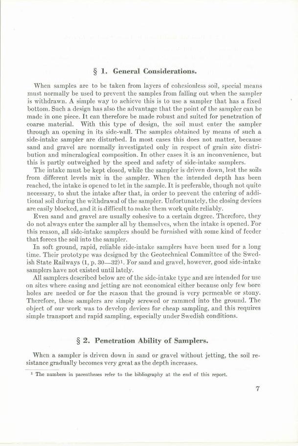
Fig. 1. Compression stress in rod pushed down in sand as a function of diameter and depth.
1 This assumption is very bold, as very little is known about the earth pressure. It may very possibly be much lower than here assumed, see (2, p. 67) .
* Properly speaking, this Yalue is applicable only if there is no skin resistance, and even then it can merely be a rough estimate.
8
Pushing force 5 10 15 t
.r: 10 L--'----'---'---------<.________, +a. QJ
"O
0, C
> ·c 0 20 1-----'~-----1------'-------1--------l
30 ,_____....,,__.._______~_____......,
m
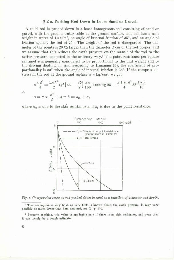
Fig. 2. Requisite pushing force as a function of cliameter ancl clepth.
In Fig. 1 we have plotted a,, and a against h for cl= 2 cm and d = 6 cm, i.e . the practical limits of d, down to h = 30 m, which may be regarded as the practical limit of h. Though the diagram is of course very approximate, just as the preceding computation, it is seen that the skin resistance is predominant. Thus, it is only the upper part of t he rod that is exposed to a great stress. This stress is not excessive, not even in ordinary st eel.
On the basis of Fig. 1 we have computed the requisite pushing force for d = = 2 cm and d = 6 cm and plotted it in Fig. 2 against the driving depth. We see that, even at moderate depth, the requisite driving force becomes so great that pushing would be unpracticable if one demanded, as we do, that the equipment should be easily portable.
§ 2 b. Screwing Rod Down in Loose Sand or Gravel.
If the rod considered in § 2 a is turned, and not pushed, the maximum shearing stress in the rod occurs at the soil surface, and this stress is computed from
n 3 l.o h2 2 ( n d d35)
16 d 1: = -2- tg 45 - 100 1 000 tg 252 2 Thus
h2 'r: = 5.05 d
In Fig. 3 we have plotted. against h ford= 2 cm and d = 6 cm.
9
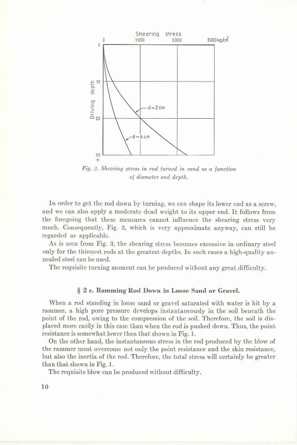
Shearing stress o 1000 2000 3000ko/4rJ0----------------
£_ 10 a. QJ -0
O> C:
> ·c o 20 1--~~----'1.---------al----~
30 '-----_.__-'-----~-~--~ m
Fig. 3. Shearing stress in rod turned in sand as a function
of diameter and depth.
In order to get the rod down by turning, we can shape its lower end as a screw, and we can also apply a moderate dead weight to its upper end. It follows from the foregoing that these measures cannot influence the shearing stress very much. Consequently, Fig. 3, which is very approximate anyway, can still be regarded as applicable.
As is seen from Fig. 3, the shearing stress becomes excessive in ordinary steel only for the thinnest rods at the greatest depths. In such cases a high-quality annealed steel can be used.
The requisite turning moment can be produced without any great difficulty.
§ 2 c. Ramming Rod Down in Loose Sand or Gravel.
When a rod standing in loose sand or gravel saturated with water is hit by a rammer, a high pore pressure develops instantaneously in the soil beneath the point of the rod, owing to the compression of the soil. Therefore, the soil is displaced more easily in this case than when the rod is pushed down . Thus, the point resistance is somewhat lower than that shown in Fig. 1.
On the other hand, the instantaneous stress in the rod produced by the blow of the ramrner must overcome not only the point resistance and the skin resistance, but also the inertia of the rod. Therefore, the total stress will certainly be greater than that shown in Fig. 1.
The requisite blow can be produced without difficulty.
10
§ 2 d. Conditions in Dense Sand or Gravel.
The driving resistance in dense sand or gravel is of a higher order of magnitude than that shown in Figs. 1 to 3. Ramming is the only possible method, and the rod should be made of high-quality annealed steel.
The blow of the rammer produces an instantaneous pressure decrease in the pore water beneath the point. This decrease is caused by the tendency of the compact soil to expand when disturbed. On account of this phenomenon, the point resistance is greater than otherwise.
On the other hand, the blow of the rammer initiates a compression wave, which travels downwards to the point, is partially reflected upwards, etc. If the soil is very dense this elastic movement is of the same order of magnitude as the penet ration of the rod per blow. Then the skin resistance does not act simult aneously along the whole rod. On account of this phenomenon, the average skin resistance is smaller than otherwise.
Fortunately, natural layers of sand or gravel are seldom dense.
§ 2 e. Conditions in Stony Sand or Gravel.
If the soil is loose, the rod can displace small stones and deviate from large ones. Therefore, a thick rod should be used if most stones are small, and a thin rod should be employed if they are large. In both cases a high-quality annealed or hardened steel should be used.
If the soil is dense, even small stones will cause difficulties. In this case it will be very helpful to shape the point so as to enable it to split stones.
§ 2 f. Penetration Ability of Sampler Compared with That of Rod.
§§ 2 a to 2 e referred to a solid rod. The conditions in the case of a sampler will be somewhat different.
Firstly, every joint implies a weakness. This is a serious drawback, particularly in consideration of the bending of the sampler rod in stony ground. The weakness can be limited by using special joints whose parts are made of steel of very high quality.
Secondly, a cross section through the chamber of a sampler is normally comparatively weak, particularly in the uppermost chamber of a sampler containing many chambers. The only remedy is to use steel of very high quality.
§ 3. Sampler Withdrawn after Taking Each Sample.
The sounding device, 19 mm in diameter, designed by the Geotechnical Committee of the Swedish State Railways (1, p. 25-29), is a handy tool having a good penetration ability in soft or loose soils. Therefore, it is used by the Institute on nearly all boring sites. In 1939 we conceived the idea of a small sampler that could
11
be coupled to the lo,ver end of this sounding rod, immediately above its screw point, and could be driven down together with the rod in the ordinary way by means of applied dead-weights and by turning clockwise. As the sounding rod cannot withstand turning counter-clockwise, samplers similar to that designed by the Geotechnical Committee (see § 1) cannot be used in this way.
Several models were made of a side-intake sampler that could be coupled to the sounding rod and would be capable of taking one small disturbed sample each time it was driven into the ground.
§ 3 a. Model 11.
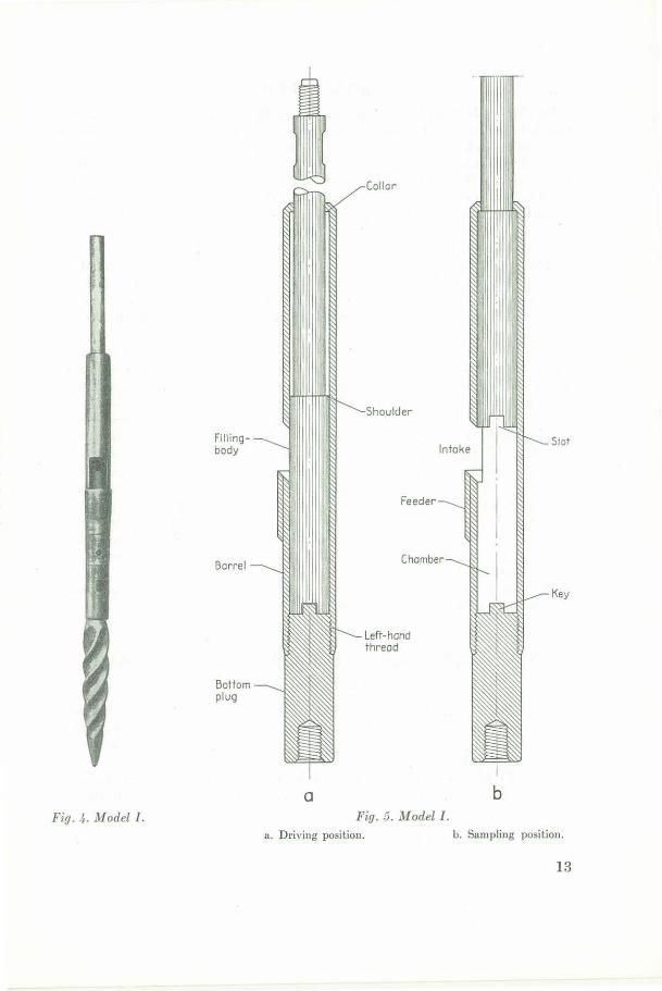
The Model I Sampler is shown in Figs. 4 and 5. It consists of a barrel, 25 mm in inner diameter, a threaded bottom plug, and a filling-body, which can be moved inside the barrel. The barrel has a side-intake and, below this intake, a feeder in the shape of a protruding lip.
When the sounding rod, with the sampler inserted immediately above the screwpoint, is driven down into the ground, the filling-body is in its lowest position in relation to the barrel (see Fig. 5 a), and no soil can enter the sampler. The torsion is transmitted through the sampler by means of a slot in the lower end of the filling-body engaging a key in the bottom plug.
After the desired depth has been reached, the rod, and hence the whole sampler, are turned a little, so that the lip is removed from the channel in the soil that it may have formed, when the sampler was driven down. Then the rod, and hence the filling-body, are lifted a short distance, the barrel being kept in its position by the surrounding soil. When the filling-body has been raised so high that its shoulder abuts against the collar at the upper encl of the barrel, the intake is free, and the chamber formed in the lower part of the barrel is ready to receive the sa,mple (sec Fig. 5 b). When the rod is now lifted higher, the whole sampler follows this motion, and the lip feeds soil into the chamber, until the latter is filled.
The sampler is then pulled out of the ground. Thanks to the shape of the chamber there is no danger of the sample being washed out during this operation. Soils from different levels may enter and mix in the uppermost part of the chamber. But it is quite certain that the lower part of the sample originates from the greatest depth to which the intake was driven . The sampler is emptied by unscrewing the bottom plug.
When sampling close to the soil surface, a larger lip is sometimes necessary . Therefore, an additional lip can be attached by screws on the outside of the lip shown in Fig. 5.
The sampler is still occasionally used by the Institute, particularly in those cases where only a few samples are wanted from each bore hole. For instance, it is used for taking samples from a thin layer of sand below a thick clay deposit. For loose sand, it has proved quite suitable. In silt it may be blocked by grains entering the space between the barrel and the filling-body.
1 Designed in 1939 by Mr. S. Odenstad, now head of the Consulting Department of the Institute.
12
a
Collar
Shoulder
Fillingbody lntoke
Feeder
ChomberBorre!
left-hand thread
Bollom plug
Slot
Key
b Fig. 4. Model I . Fig. 3. Model I .
a. Dri ving posilion. b. Sampling position.
13
§ 3 b. Model 111.
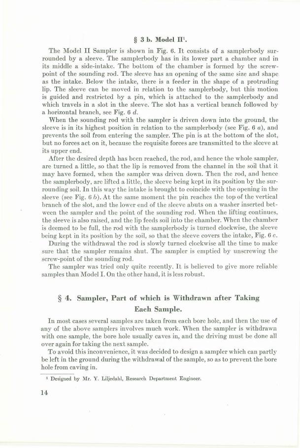
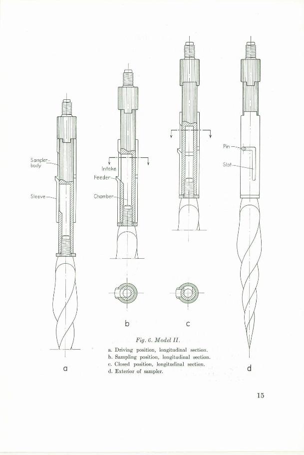
The )fodel II Sampler is shown in Fig. 6. It consists of a samplerbody surrounded by a sleeve. The samplerbody has in its lower part a chamber and in its middle a side-intake. The bottom of the chamber is formed by the screwpoint of the sounding rod. The sleeve has an opening of the same size and shape as the intake. Below the intake, there is a feeder in the shape of a protruding lip. The sleeve can be moved in relation to the samplerbody, but this motion is guided and restricted by a pin, which is attached to the samplerbody and which travels in a slot in the sleeve. The slot has a vertical branch followed by a horizontal branch, see Fig. 6 d.
When the sounding rod with the sampler is driven down into the ground, the sleeve is in its highest position in relation to the samplerbody (see Fig. 6 a), and prevents the soil from entering the sampler. The pin is at the bottom of the slot, but no forces act on it, because the requisite forces are transmitted to the sleeve at its upper end.
After the desired depth has been reached, the rod, and hence the whole sampler, are turned a little, so that the lip is removed from the channel in the soil that it may have formed, when the sampler was driven down. Then the rod, and hence the samplerbody, are lifted a little, the sleeve being kept in its position by the surrounding soil. In this way the intake is brought to coincide with the opening in the sleeve (sec Fig. 6 b) . At the same moment the pin reaches the top of the vertical branch of the slot, and the lower end of the sleeve abuts on a washer inserted between the sampler and the point of the sou nding rod. When the lifting continues, the sleeve is also raised, and the lip feeds soil into the chamber. When the chamber is deemed to be full, the rod with the samplerbody is turned clockwise, the sleeve being kept in its position by the soil, so that the sleeve covers the intake, Fig. 6 c.
During the withdrawal the rod is slowly turned clockwise all the time to make sure that the sampler remains shut. The sampler is emptied by unscrewing the screw-point of the sounding rod.
The sampler was tried only quite recently. It is believed to give more reliable samples than Model I. On the other hand, it is less robust.
§ 4,. Sampler, Part of which is Withdrawn afte1· Taking
Each Sample.
In most cases several samples are taken from each bore hole, and then the use of an;v of the above samplers involves much work. When the sampler is withdrawn with one sample, the bore hole usually caves in, and the driving must be done all over again for taking the next sample.
To avoid this inconvenience, it was decided to design a sampler which can partly be left in the ground during the withdrawal of the sample, so as to prevent the bore hole from caving in.
1 Designed by Mr. Y. Liljedahl, Research Department Engineer.
14
Samplerbody
Sleeve
+
•I •b C
Fig. 6. Model II.
a . Driving position, longitudinal section. b. Sampling position, longitudinal section. c. Closed position, longitudinal section.
a dd. Exterior of sampler.
15
§ 4 a. Model A1 •
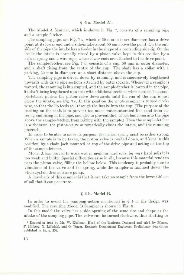
The :i\fodel A Sampler, which is shown in Fig. 7, consists of a sampling pipe and a sample-fetcher.
The sampling pipe, see Fig. 7 a, which is 50 mm in inner diameter, has a drive point at its lower end and a side-intake about 50 cm above the point. On the outside of the pipe the intake has a feeder in the shape of a protruding side-lip. On the inside the intake is normally closed by a piston-valve kept in this position by a helical spring and a wire-rope, whose lower ends are attached to the drive point.
The sample-fetcher, sec Fig. 7 b, consists of a cup, 50 mm in outer diameter, and a shaft rising from the centre of the cup. The shaft has a collar with a packing, 50 mm in diameter, at a short distance above the cup.
The sampling pipe is driven down by ramming, and is successively lengthened upwards with drive pipe sections attached by outer sockets. Whenever a sample is wanted, the ramming is interrupted, and the sample-fetcher is lowered in the pipe, its shaft being lengthened upwards with additional sections when needed. The sample-fetcher pushes the piston-valve downwards until the rim of the cup is just below the intake, see Fig. 7 c. In this position the whole sampler is turned clockwise, so that the lip feeds soil through the intake into the cup. (The purpose of the packing on the shaft is to prevent too much water-saturated fine sand from entering and rising in the pipe, and also to prevent dirt, which has come into the pipe above the sample-fetcher, from mixing with the sample.) Then the sample-fetcher is withdrawn, the piston-valve automatically closes the intake, and the ramming proceeds.
In order to be able to serve its purpose, the helical spring must be rather strong. When a sample is to be taken, the piston valve is pushed down, and kept in this position, by a chain jack mounted on top of the drive pipe and acting on the top of the sample-fetcher.
Model A has proved to work well in medium-hard soils; for very hard soils it is too weak and bulky. Special difficulties arise in silt, because this material tends to pass the piston-valve, filling the hollow below. This tendency is probably due to vibrations of the valve and the spring, while the sampler is rammed down; the whole system then acts as a pump.
A drawback of this sampler is that it can take no sample from the lowest 50 cm of soil that it can penetrate.
§ 4 h. Model B.
In order to avoid the pumping action mentioned in § 4 a, the design was modified. The resulting Model B Sampler is shown in Fig. 8.
In this model the valve has a side opening of the same size and shape as the intake of the sampling pipe. The valve can be turned clockwise, thus shutting or
1 Devised in 1943 by Mr. W. Kjellman, Read of the Institute. Designed and tried by Messrs. F. Hillberg, Y . Liljedahl, and 0. Wager, Research Department Engineers. Preliminary description published in (4, p . 25) .
JG
Feeder
Pi:;ton-volve
Spring
Wire-rope
Pocking
Shaft
Cup
a b C
Fig. 7. Model A.
a. Sampling pipe in driving position. b. Sample-fetcher. c. Sampler in sampling position.
17
Feeder
Pi5tonvalve
Pocking
Shaft
Key Cup
Point
Intake
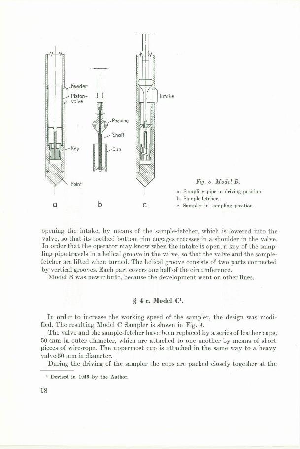
Fig. 8. Model B.
a. Sampling pipe in driving position. b. Sample-fetcher.
a b C c. Sampler in sampling position.
opening the intake, by means of the sample-fet cher, which is lowered into the valve, so that its toothed bottom rim engages recesses in a shoulder in the valve. In order that the operator may know when the intake is open, a key of the sampling pipe travels in a helical groove in the valve, so that the valve and the samplefetcher are lifted when turned. The helical groove consist s of two parts connected by vertical grooves. Each part covers one half of the circumference.
Model B was newer built, because the development went on other lines.
§ 4 c. Model C1•
In order to increase the working speed of the sampler, the design was modified. The resulting Model C Sampler is shown in Fig. 9.
The valve and the sample-fetcher have been replaced by a series of leather cups, 50 imm in outer diameter, which are attached to one another by means of short pieces of wire-rope. The uppermost cup is attached in the same way to a heavy valve 50 mm in diameter.
During the driving of the sampler the cups are packed closely together at the
1 Devised in 1946 by the Author.
18
Drive pipe
Valve
Cups
Point
Feeder
Wire-rope
Intake
Wire-rope
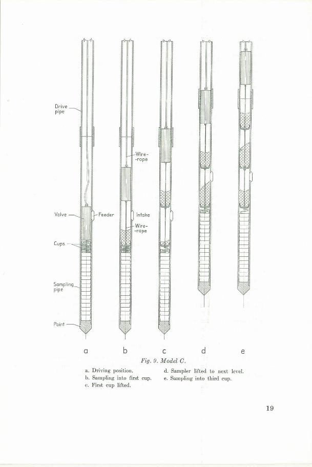
a b C d e Fig. 9. Model C.
a . DriYing position. d. Sampler lifted to next b·el. b. Sampling into first cup. e. Sampling into third cup. c. First cup lifted.
19
bottom of the drive pipe, the valve covering the intake, sec F ig. 9 a. At t he desired depth the valve is lifted a little by means of a wire-rope extending above the ground surface, and the sampler is turned, so that soil is fed into the first cup, see Fig. 9 b. Then this cup is raised above the intake (Fig. 9 c), and the whole sampler is lifted to the next sampling level (Fig. 9 d) . The soil that enters during this operation is collected in the second cup. Now this cup is lifted above the intake, and the third cup is filled by turning, see Fig. 9 e. In this way sampling can continue as far as the number of cups permits. Every second cup contains a correct sample from a certain definite level, and the other cups carry a mixture of the layers bet ween two levels,
One sampler of this kind was built and tried. It worked as intended, though the placing of the cups at the bottom of the drive pipe proved troublesome. After a short time the sampler was lost at a great depth. It was not replaced because new samplers had been devised in the meantime.
§ 5. Sampler Withdrawn Only Once after Sinking
Each Bore Hole.
In 1946 a long core of clay had for the first time been taken in one operation by means of the foil sampler (2) . This success encouraged us to devise a side-intake sampler capable of taking in one operation a very long sample, or a series of samples, in sand or gravel. Two types of sampler which resulted from this development are described below.
§ 5 a. Wager's1 Sampler.
§ 5 a 1. Principle.
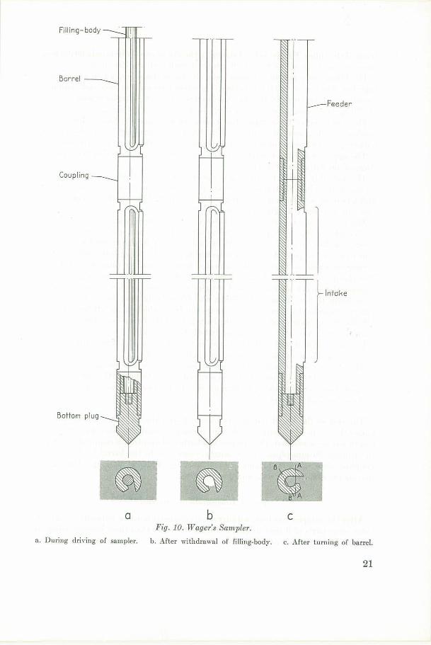
Wager's Sampler consist s in principle of a barrel and a filling-body, see Fig. 10. The barrel has a side-intake in the shape of a longitudinal slot and a feeder in the shape of a longitudinal protruding lip.
During the driving of the sampler the filling-body prevents soil from entering, see Fig. 10 a. When the greatest depth from which samples are wanted has been reached, the filling-body is withdrawn, see Fig. 10 b, so that a chamber is formed. Then the sampler is turned clockwise, and the lip feeds soil into the chamber, see Fig. 10 c . Finally, the barrel is withdrawn.
§ 5 a f2 . Details.
The barrel consists of steel tubes 1 m in length, 45 mm in outer diameter, and 20 mm in inner diameter. They are connected by means of outer couplings made of high-quality steel. The outside and the inside of the couplings are flush with
1 Designed in 1946 by Mr. 0. Wager, Research Department Engineer, in cooperation with the Author. Preliminary description published in (5).
20
Filling-body
l Barrel
Feeder
Coupling
J.
r Intake
Bottom plug
a b C Fig. 10. Wager's Sampler.
a. During dri,·ing of sampler. b . After withdrawal of filling-body. c. After turning of barrel.
21
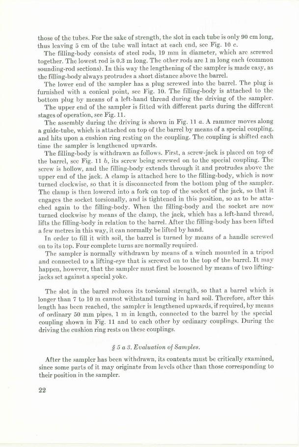
those of the tubes. For the sake of strength, the slot in each tube is only 90 cm long, thus leaving 5 cm of the tube wall intact at each end, see Fig. 10 c.
The filling-body consists of steel rods, 19 mm in diameter, which are screwed together. The lowest rod is 0.3 m long. The other rods are 1 m long each (common sounding-rod sections). In this way the lengthening of the sampler is made easy, as the filling-body always protrudes a short distance above the barrel.
The lower end of the sampler has a plug screwed into the barrel. The plug is furnished with a conical point, sec Fig. 10. The filling-body is attached to the bottom plug by means of a left-hand t hread during the driving of the sampler.
The upper end of the sampler is fitted with different parts during the different stages of operation, see Fig. 11.
The assembly during the driving is shown in Fig. 11 a. A rammer moves along a guide-tube, which is attached on top of the barrel by means of a special coupling, and hits upon a cushion ring resting on the coupling. The coupling is shifted each time the sampler is lengthened upwards.
The filling-body is withdrawn as follows. First, a screw-jack is placed on top of the barrel, see F ig. 11 b, its screw being screwed on to the special coupling. The screw is hollow, and the filling-body extends through it and protrudes above the upper end of the jack. A clamp is attached here to the filling-body, which is now turned clockwise, so that it is disconnected from the bottom plug of the sampler. The clamp is then lowered into a fork on top of the socket of the jack, so that it engages the socket torsionally, and is tightened in this position, so as to be attached again to the filling-body. When the filling-body and the socket are now turned clockwise by means of the clamp, the jack, which has a left-hand thread, lifts the filling-body in relation to the barrel. After the filling-body has been lifted a few metres in this way, it can normally be lifted by hand.
In order toi fill it with soil, the barrel is turned by means of a handle screwed on to its top. Four complete turns are normally required.
The sampler is normally withdrawn by means of a winch mounted in a tripod and connected to a lifting-eye that is screwed on to the top of the barrel. It may happen, however, that the sampler must first be loosened by means of two liftingjacks set against a special yoke.
The slot in the barrel reduces its torsional strength, so that a barrel which is longer than 7 t o 10 m cannot withstand turning in hard soil. Therefore, after this length has been reached, the sampler is lengthened upwards, if required, by means of ordinary 50 mm pipes, 1 m in length, connected to the barrel by the special coupling shown in Fig. 11 and to each other by ordinary couplings. During the driving the cushion ring rests on these couplings.
§ 5 a 3. Evaluation of Samples.
After the sampler has been withdrawn, its contents must be critically examined, since some parts of it may originate from levels other than those corresponding to their position in the sampler.
22
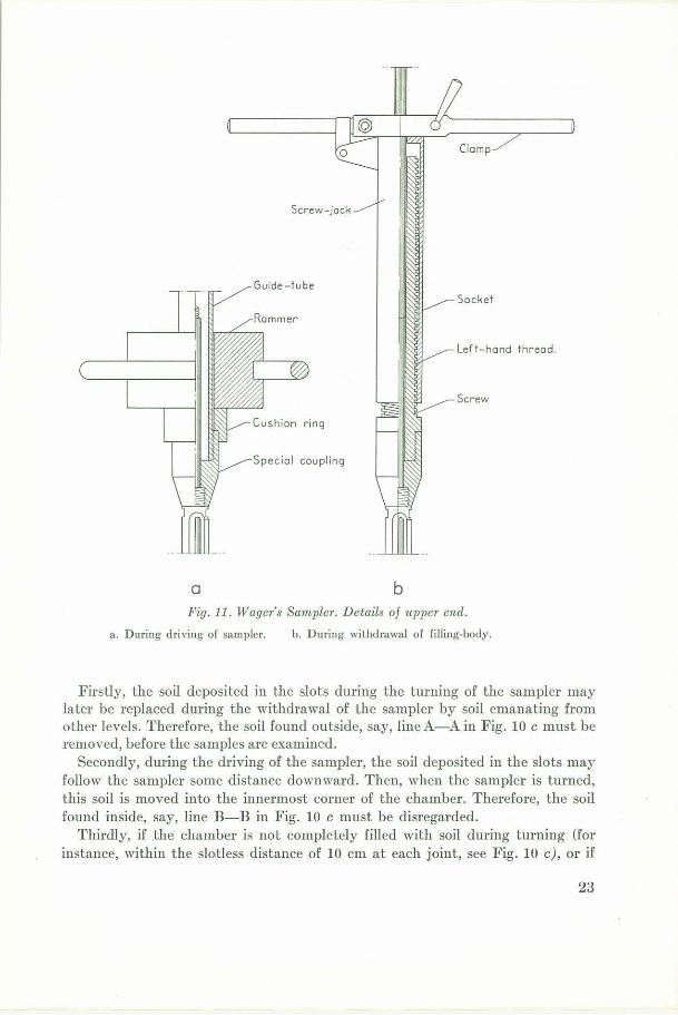
Guide-tube
Clomp
Screw-jock
Socket
Left-hand thread.
a b Fig.11. Wager's Sampler. Details of upper encl.
a. During dri,· ing of sampler. b. During wilhdrawal of filling-body.
Firstly, the soil deposited in the slots during the turning of the sampler may later be replaced during the withdrawal of the sampler by soil emanating from other levels. Therefore, the soil found outside, say, line A-A in Fig. 10 c must be removed, before the samples are examined.
Secondly, during the driving of the sampler, the soil deposited in the slots may follow the sampler some distance downward. Then, when the sampler is turned, this soil is moved into the innermost corner of the chamber. Therefore, the soil found inside, say, line B-B in Fig. 10 c must be disregarded.
Thirdly, if the chamber is not completely filled with soil during turning (for instance, within the slotless distance of 10 cm at each joint, see Fig. 10 c), or if
23
part of the soil is washed out during the withdrawal, the samples may moYe axially inside the sampler during its subsequent withdrawal, and the cavities may even be filled with soil from higher levels. For these reasons, not even that part of sample which is found between lines A-A and B-B in Fig. 10 c is always quite reliable.
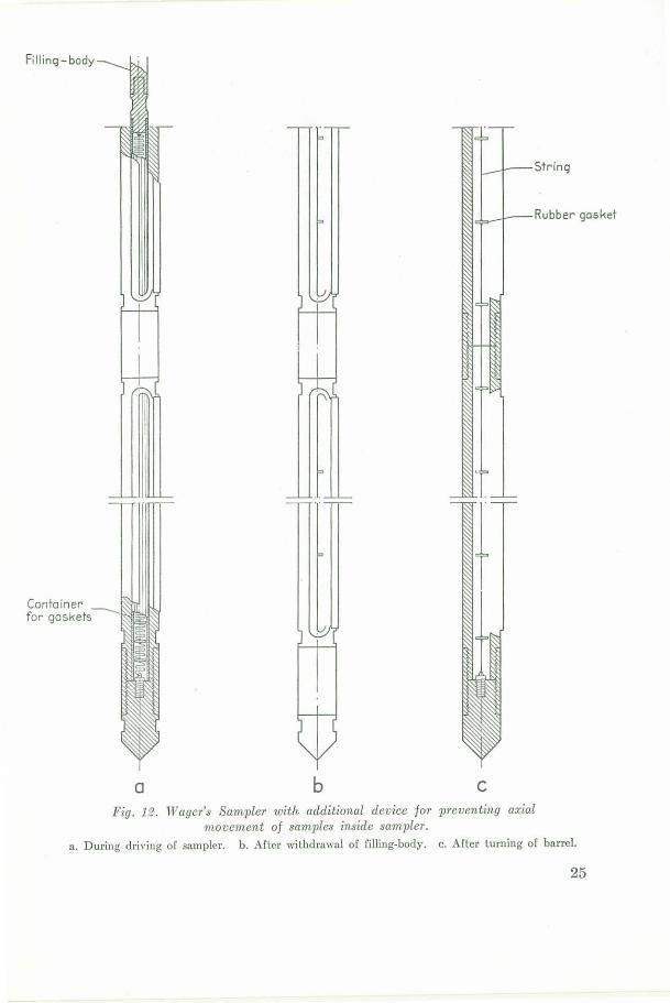
§ 5 a 4. Additi:onal Device.
The main imperfection of the sampler, namely, the axial movement of the samples in relation to the sampler, can be eliminated by means of the additional deYice shown in Fig. 12. It consists of a series of rubber gaskets attached at definite intervals to a string, whose lower end is fastened to the bottom plug of the sampler. During the driving of the sampler the gaskets are packed closely together in a tightfitting container forming the lower part of the filling-body. After the desired depth has been reached, the filling-body, together with the container, is ,Yithdrawn, leaving the gaskets consecutively as the string gets tight, sec Fig. 12 b.
§ 5 a 5. Sampler in Practice.
Wager's Sampler is comparatively light, and it works rapidly and cheaply in loose to medium-dense soils. Its average life is 150 to 200 working-days in mediumdense sand or gravel.
The device shown in Fig. 12 has been tested and found to work as intended. However, it proved cumbersome, when t he sampler had to be cleaned.
Wager's Sampler was frequently used by the Institute in 1947 to 1951. It is still occasionally employed.
§ 5 b. Kallstenius's1 Sampler.
In order to eliminate the sources of error mentioned in § 5 a 3 and to improYe the penetration ability, a new sampler was developed.
§ 5 b 1. Principle.
The main part of the sampler, the samplerbody, is made of a heavy steel rod provided with closely-spaced transverse holes. The holes form small chambers with unidirectional side-intakes, see Fig. 13. All intakes can be covered by a shutter which runs longitudinally at the side of the samplerbody, its edges being guided by two grooves in the latter.
During the driving of the sampler the intakes are covered by a shutter consisting of a strip of sheet-steel, see Fig. 13 a. After the desired depth has been reached, this sheet shutter is withdrawn, leaving the chambers open. Then another shutter is rammed down. It consists of a series of steel plates, the lowest of which
1 Devised by the Author in 1949. Designed by Mr. R. Riper, :Mechanical Department Engineer. Field experiments made Mr. I. Bellhester, of the Consulting Department.
24
Filling-body
String
Rubber gasket
Container for gaskets
a b C
Fig. lfd . Wager's Sampler with additional device for preventing axial movement of samples inside sampler.
a. During driving or sampler. b. After withdrnwal of filling-body. c. After turning of barrel.
25
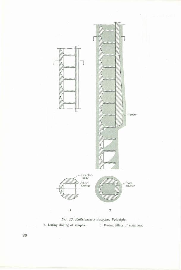
Feeder
Samplerbody
~fL-«==!:f" ~Sheet Plate shutter st,utter
a b
Fig. 13. Kallsteni1ts's Sampler. Principle.
a. During driving of sampler. b. During filling of chambers.
26
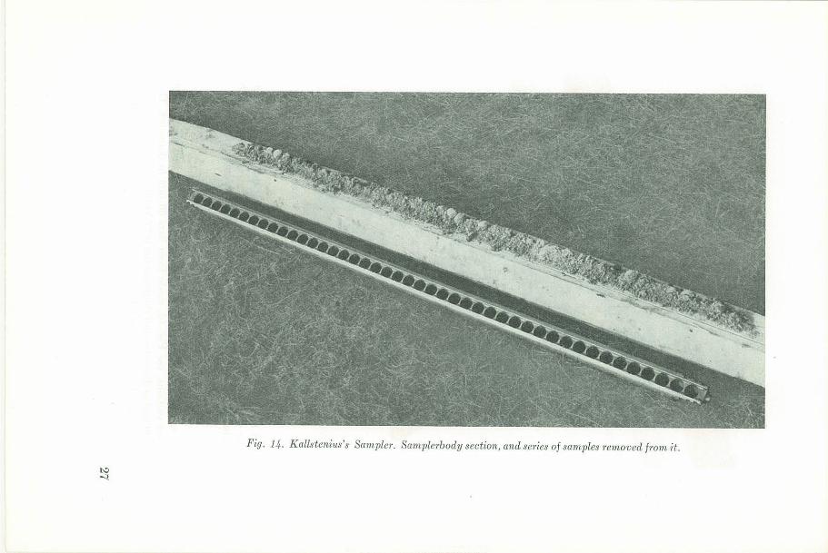
Fig. 14. Kallstcnius's Sam7Jler. Samplerbody sect-ion, and series of samples removed frorn it.
1:-.:> ~
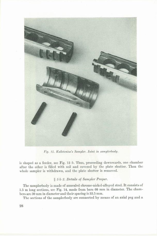
Fig. 15. Kallstenius's Sampler. Joint in samplerbody .
is shaped as a feeder, see Fig. 13 b. Thus, proceeding downwards, one chamber after the other is filled with soil and covered by the plate shutter. Then the whole sampler is withdrawn, and the plate shutter is removed.
§ 5 b f2 . D etails of Sampler Proper.
The samplerbody is made of annealed chrome-nickel-alloyed steel. It consists of 1.5 m long sections, see Fig. 14, made from bars 60 mm in diameter. The chambers are 30 mm in diameter and their spacing is 33.5 mm.
The sections of the samplerbody are connected by means of an axial peg and a
28
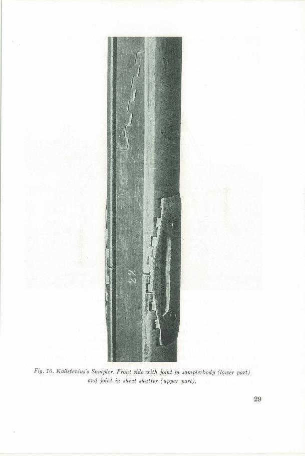
Fig. 16. Kallsteniu~·s Sarnpler. Front side with joint in sarnplerbody (lower part)
and joint in sheet shutter (upper part).
29
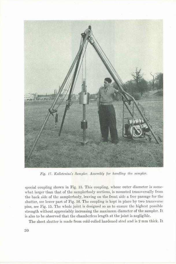
Fig. 17. Kallstenius's Sampler. Assembly for handling the sampler.
special coupling shown in Fig. 15. This coupling, whose outer diamet er is somewhat larger than that of the samplerbody sections, is mounted transversally from the back side of the samplerbody, leaving on the front side a free passage for the shutter, see lower part of Fig. 16. The coupling is kept in place by two transverse pins, see Fig. 15. The whole joint is designed so as to ensure the highest possible strength without appreciably increasing the maximum diameter of the sampler. It is also to be observed that the chamberless length at the joint is negligible.
The sheet shutter is made from cold-rolled hardened steel and is 2 mm thick. It
30
consists of sections 1.5 m in length with a very simple joint which can withstand pulling, see upper part of Fig. 16.
The plate shutter is made from cold-rolled hardened steel and consists of sections 0.2 min length which simply abut against each other. All sections are 10 mm thick except the lowest one, i.e. the feeder. According to the soil conditions, four different feeders are used. Their lower ends are 15, 20, 25, and 30 mm thick, respectively. The inclination of the lower end surface shown in Fig. 13 b was found to be suitable, since it prevents the feeder from being torn out of the guiding grooves and helps stones to escape when they are too large to ent er the chambers. A stone which has partially entered a chamber is cut between the edge of the feeder and that of the lower wall of the hole.
The lower end of the sampler is furnished with a point made from hardened steel. It is attached to the lowest section of the samplerbody by means of a thick axial peg and a transverse pin. The shape of the point has been tried out. A small-angle cone together with a chisel-shaped end were found to be best.
§ 5 b 3. [fondling.
The sampler is handled by means of the assemblyl shown in Fig. 17. An internal-combustion engine of 5 H.P. mounted on a frame which forms part of a threelegged derrick drives a capstan. An endless wire-rope is loosely slung from this capstan over a sheave at the top of the derrick. This sheave can be adjusted by means of a lever so as to tighten the wire-rope on the capstan. This wire-rope is connected by means of a yoke to two other wire-ropes, which run over sheaves at the top of the derrick and whose ends are attached to an 80 kg rammer. When the operator pulls the lever, the rammer is lifted, and when he pushes it, the rammer falls.
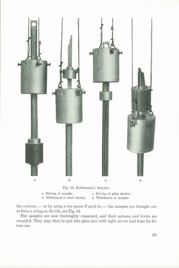
During the driYing of the sampler, see Fig. 18 a, the rammcr is directed by a guide-rod mounted on top of the samplerbody by means of a coupling, whose outside is flush with that of the samplerbody. The rammer forces down the heads of two wedges inserted between the samplerbody and a heavy outer ring2 . These wedges cover the whole circumference of the samplerbody, and protrude above and below the ring. The sheet shutter follows the downward motion of the samplerbody on account of a smaller wedge inside the two large ones. When the wedges approach the ground surface, a fork is placed on the top of the ring, so that the blow of the rammer is transferred to the outer ring instead of hitting the wedges. If the wedges do not loosen at once, they loosen a little later, when their lower ends hit upon a steel slab placed on the ground surface. Then the wedges and the ring are set on a higher level, and the ramming proceeds, until the desired depth has been reached.
For the withdrawal of the sheet shutter, see Fig. 18 b, two wedges are inserted with their heads upwards between the sheet shutter and an outer ring. The rammer moves upwards and hits upon the ring. After a withdrawal of a few metres, the
1 Designed and built by Barros A.B., Stockholm, in partial cooperation with the Institute. 2 The lock formed by the two wedges and the ring was devised and patented by Barros A.B.
31
shutter can normally be completely extracted simply by pulling with the aid of the motor and the winch, whose wire-rope is then attached to the ring.
During the driving of the plate shutter, see Fig. 18 c, the rammer is directed b_y the above-mentioned guide--rod mounted on top of the samplerbody. The rammer hits upon a heavy ring, from which the blow is transmitted to the top of the shutter by a nose-shaped steel piece. Now and then the rammer and the ring with its »nose» are lifted, and a new shutter section is inserted sidewards into a groove in the guide-rod and moved downwards into the grooves of the samplerbody. This procedure1 is repeated until all those shutter sections which were beforehand considered to be necessary for reaching the bottom of the sampler have been driven down. (Otherwise it would be difficult to know whether one has reached the bottom of the sampler or merely a stone.)
During the withdrawal of the sampler, see Fig. 18 d, use is made of the same wedges and ring as during the driving of the sampler, but they are applied upside down. The rammer forces the heads of the wedges upwards. As soon as the sampler has loosened sufficiently, the withdrawal is continued by simple lifting with the aid of the winch, whose wire-rope is th en attached to a lifting-eye at the upper end of the guide-rod.
§ 5 b 4- Eval·uation of Samples.
Owing to the funn el-shaped hole around the sampler that may develop down to a depth of a few metres during the driving of the sampler, soil may fall down some distance in this hole and enter the sampler on a false level. Therefore, if a funnel is formed, it is better to discard the samples found in the upper 2 m of the sampler and make a separate sampling down to a depth of 2 m.
Normall?, the feeder does not push soil downwards any appreciable distance before feeding it into the chambers. It has happened, however, that the feeder -particularly the largest one - has pushed hard clay a few centimetres down in an underlying fine sand, before feeding it into the chambers.
During the driving of the sampler, small quantities of silt and fine sand may enter through the joints in the shee t shutter and at its edges. We have found, ho,Yever, that this fine material normally settles down firmly in the lowest part of each chamber, where it can easily be distinguished from the sample proper.
Comparisons with bore holes made in ather ways and with test-pits have confirmed that, apart from the small errors mentioned above, the samples actually originate from levels corresponding to their positions in the sampler.
When the samples are to be examined, the plate shutter is removed - with a hammer if need be. Then the samplerbody sections are placed horizontally with the intakes downwards on a tile. By knocking lightly with a hammer on the back of
1 Owing to the vibrations during the driving of the sampler, a funnel-shaped hole may ha,·e formed around its upper part. Therefore, the upper part of the samplerbody should be pressed forward during the driving of the first 10 or 20 sections of the plate shutter, in order that the feeder may be able to fill the chambers with soil.
32
a b C d
Fig. 18. Kallsteni11s's Sampler.
a . Driving of sampler. c. Driving of plate shutter. b. Withdrawal of sheet shutter. d. ,vithdrawal of sampler.
the sections - or by using a tea-spoon if need be - the samples are brought out to form a string on the tile, see Fig. 14.
The samples are now tho·roughly examined, and their natures and levels are recorded. They may then be put into glass-jars with tight covers and kept for future use.
33
§ 5 b 5. Sampler in Practice.
The penetration ability of the sampler in hard stony ground has proved to be better than that of any other portable sampler tried by us, and is probably better than that of any other portable sampler known to us. Since it hardly ever happens that some chambers are found to be empty or that a whole bore hole fails, the sampling efficiency is high. The working speed is on an average about 15 m of samples per 8 hours.
Of course, the different parts of the sampler differ in life. The sheet shutter and the couplings must be replaced after about 100 working-days, but the samplerbody sections and the handling device can be used a much longer time. The necessary current repairs of the sampler are moderate.1
The sampler is very expensive in construction owing to the high price of the requisite steel and the difficulty of machining this steel, and also owing to the fact that so much machining is needed. In hard soils, however, it is cheaper in use than other samplers, because it works safely and rapidly.
At the end of 1952 samplers of this type had been used by the Institute for about 400 working-days - generally for jobs lasting only a few clays each.
§ 6. Prospective Development of Side-Intake Samplers.
The samplers mentioned in the previous sections may of course be improved or altered to suit other conditions.
At present a modified t ype of Model II Sampler is in process of design. There will be a permanent demand for a cheap sampler suitable for use as a supplementary part which is always at hand when sounding.
A probable development of the samplers described in § 4 is a heavy sampler t o be hammered into stony gravel by means of ordinary pile-driving equipment. Such a sampler would permit the taking of large samples.
The design of a special type of Kallstenius's Sampler will soon be completed. This type is intended for rapid sampling in loose ground. It will be cheaper to make than the existing type but the sa mpling safety will be the same.
§ 7. Summary.
The development of portable side-intake samplers at the Royal Swedish Geotechnical Institute has resulted in three types of samplers designed for different fields of application:
a) Supplementary parts of the sounding device. They have a feeder in the shape of a pushing lip and only one chamber, which is fixed. They are cheap to make.
1 It pays to use the best steel a \'ailable for the sampler. Tests on a sampler made from carbonsteel (C = 0.50 %) resulted in a much shorter life and in much more repairs.
34
Their penetration ability and sampling safety are not so high as those of the other types.
b) Samplers, part of which is "·ithdrawn after taking each sample. They have a feeder in the shape of a turning lip and have one or seYeral separately movable chambers. They are comparatively bulky and their penetration ability is not so high as in the next group. On the other hand, they permit the taking of the biggest samples. They are cheaper in construction but more expensive in use than the next type.
c) Samplers for taking very many samples in one operation. These samplers have the best penetration ability and permit rapid "·ork. This type of sampler takes fairly small samples but permits a complete survey of the soil stratification in a way that is not possible with any other knom1 type of side-intake samplers. Kallstcnius's sampler is particularly expensive in manufacture, but cheap in use.
Bibliography.
1. Statens jarnvagar: Gcotekniska kommissionen 1914-1922. Slutbctankande. Stockholm 1922. (Stat. Janw. Geot. Medel. Nr 2).
2. KJELLl\IAN, W., KALLSTE:'.'l"ICS, T., and WAGER, 0., Soil Sampler with :.\Ietal Foils. Stockholm Hl50. (R. Swed. Geot. Inst. Proc. No. 1).
3. HUIZINGA, T. K., Application of Results of Deep Penetration Tests to Foundation Piles. Build. Res. Congr. 1931 Div. I p. 173-179.
4. Kortfattat kompendium i geoteknik 1946. Stockholm 1946. (Stat. Geot. Inst. lVIedd. Nr 1).
5. WAGER, 0 ., Extractor for Taking Disturbed Samples in Hard Ground. Proc. 2. internat. Conf. Soil 1\Iech. a. Found. Engng. 1948 Vol. 1 p. 249.
35


LIST OF PUBLICATIONS
J?ROM THE ROYAL SWEDISH GEOTECHNICAL
INSTITUTE
Proceedings
No. 1. Soil Sampler with Metal Foils. Device for Taking Undisturbed
Samples of Very Great Length. W. Kjellman, T. Kallstenius, and
0. Wager ............ . ........... . . . .. . ......... .. .. . ...... 1950
2. The Vane Borer. An Apparatus for Determining the Shear Strength
of Clay Soils Directly in the Ground. Lyman Cadling and Sten
0denstad . . . . . . . . . . . . . . . . . . . . . . . . . . . . . . . . . . . . . . . . . . . . . . . . . . . 1950
3. Device and Procedure for Loading Tests on Piles. W. Kjellman
and Y. Liljedahl . . . . . . . . . . . . . . . . . . . . . . . . . . . . . . . . . . . . . . . . . . . 1951
4. The Landslide at Skottorp on the Lidan River, February 2, 1946.
Sten Odenstad . . . . . . . . . . . . . . . . . . . . . . . . . . . . . . . . . . . . . . . . . . . . . . 1951
5. The Landslide at Surte on the Gota River, September 29, 1950.
Bernt Jalcobson ... . ...................... .. ............ .. ... 1952
6. A New Geotechnical Classification System. W. Kjellman, L. Cad-
ling, and N. Flodin ..... . ........ ... . ... ........ . ............ 1953
7. Some Side-Intake Soil Samplers for Sand and Gravel. Torsten
Kallstenius . . . . . . . . . . . . . . . . . . . . . . . . . . . . . . . . . . . . . . . . . . . . . . . . . . 1953
M eddelanden
No. I. Kortfattat kompendium i geoteknik 1946 1946
2. Redogorelse for Statens geotekniska instituts verksamhet under
aren 1944---1948 . ....................... ... ........ .. ....... 1949
3. »Bra borrat - bii.ttre byggb. Meddelande utgivet till institutets
deltagande i utstii.llningen »Bygg bii.ttre», Nordisk Byggnadsdag V 1950


![[Flip-Side] 4. Intake, Exhaust, Cylinder Flow](https://img.pdfslide.net/doc/110x75/56d6c06d1a28ab30169a58c8/flip-side-4-intake-exhaust-cylinder-flow.jpg)