Embed Size (px)
DESCRIPTION
service manual s500
Citation preview
Revision HistoryRevision History
How to useAcrobat Reader
How to useAcrobat Reader
Internal memoryON BOARD
Internal memoryON BOARD
SERVICE MANUAL
LinkLink
Sony EMCS Co.DSC-S500
SERVICE NOTE
SPECIFICATIONS
BLOCK DIAGRAMS
DISASSEMBLY REPAIR PARTS LIST
Ver. 1.3 2007.08
DIGITAL STILL CAMERA
2007H0800-1 © 2007.08
Published by Kohda TEC9-852-124-12
US ModelCanadian Model
AEP ModelUK Model
E ModelAustralian Model
Hong Kong ModelKorea Model
The components identified bymark 0 or dotted line withmark 0 are critical for safety.Replace only with part num-ber specified.
Les composants identifiés par unemarque 0 sont critiques pour lasécurité.Ne les remplacer que par une pièceportant le numéro spécifié.
DSC-S500
In case of the lens assembly, main board, or main frame assembly failure,contact your local Sony Service Headquarter for the measures.
— 2 —DSC-S500
SPECIFICATIONS
[System]Image device
7.17 mm (1/2.5 type) color CCD, Primarycolor filter
Total pixel number of cameraApprox. 6 183 000 pixels
Effective pixel number of cameraApprox. 6 003 000 pixels
Lens3× zoom lensf = 5.4 - 16.2 mm (32 - 96 mm whenconverted to a 35 mm still camera)F2.8 - 4.8
Exposure controlAutomatic exposure, Scene Selection (6modes)
White balanceAutomatic, Daylight, Cloudy, Fluorescent,Incandescent
File format (DCF compliant)Still images: Exif Ver. 2.21JPEG compliant, DPOF compatibleMovies: AVI (Motion JPEG)
Recording mediaInternal Memory (Approx. 25 MB)“Memory Stick Duo” (with MagicGate/without MagicGate)“Memory Stick PRO Duo”“MagicGate Memory Stick Duo”
Flash rangeWhen ISO set to Auto: approx. 0.5 m to2.5 m (19 3/4 inches to 98 1/2 inches) (W)/approx. 0.5 m to 2.0 m (19 3/4 inches to 783/4 inches) (T)
[Input and Output connectors]A/V OUT jack
Mini-jackVideo signal: 1 Vp-p, 75 Ω (ohms),unbalanced, sync negativeAudio signal: 2 V (at load impedance morethan 47 kΩ (kilohms))Output impedance with less than 2.2 kΩ(kilohms)
USB jackmini-B
USB communicationFull-Speed USB (USB 2.0 compliant)
[LCD screen]LCD panel
6.0 cm (2.4 type) TFT driveTotal number of dots
110 000 (480 × 234) dots
[Power, general]Power
LR6 (size AA) Alkaline batteries (2), 3 VHR15/51:HR6 (size AA) Nickel-MetalHydride batteries (2) (not supplied), 2.4 VZR6 (size AA) Oxy Nickel Primary Battery(2) (not supplied), 3 VAC-LS5K AC Adaptor (not supplied), 4.2 V
Power consumption(during shooting with the LCD screen on)
1.6 WOperating temperature
0 to 40°C (32 to 104°F)Storage temperature
–20 to +60°C (–4 to +140°F)Dimensions
92 × 62 × 31 mm(3 3/4 inches × 2 1/2 inches × 1 1/4 inches)(W/H/D, excluding protrusions)
MassApprox. 198 g (7.0 oz) (including twobatteries and wrist strap, etc.)
MicrophoneElectret condenser microphone
BuzzerPiezo-electric buzzer
Exif PrintCompatible
PRINT Image Matching IIICompatible
PictBridgeCompatible
Design and specifications are subject to changewithout notice.
— 3 —DSC-S500
SAFETY-RELATED COMPONENT WARNING!!
COMPONENTS IDENTIFIED BY MARK 0 OR DOTTED LINE WITHMARK 0 ON THE SCHEMATIC DIAGRAMS AND IN THE PARTSLIST ARE CRITICAL TO SAFE OPERATION. REPLACE THESECOMPONENTS WITH SONY PARTS WHOSE PART NUMBERSAPPEAR AS SHOWN IN THIS MANUAL OR IN SUPPLEMENTSPUBLISHED BY SONY.
ATTENTION AU COMPOSANT AYANT RAPPORTÀ LA SÉCURITÉ!
LES COMPOSANTS IDENTIFÉS PAR UNE MARQUE 0 SUR LESDIAGRAMMES SCHÉMATIQUES ET LA LISTE DES PIÈCES SONTCRITIQUES POUR LA SÉCURITÉ DE FONCTIONNEMENT. NEREMPLACER CES COMPOSANTS QUE PAR DES PIÈSES SONYDONT LES NUMÉROS SONT DONNÉS DANS CE MANUEL OUDANS LES SUPPÉMENTS PUBLIÉS PAR SONY.
1. Check the area of your repair for unsoldered or poorly-solderedconnections. Check the entire board surface for solder splashesand bridges.
2. Check the interboard wiring to ensure that no wires are"pinched" or contact high-wattage resistors.
3. Look for unauthorized replacement parts, particularlytransistors, that were installed during a previous repair. Pointthem out to the customer and recommend their replacement.
4. Look for parts which, through functioning, show obvious signsof deterioration. Point them out to the customer andrecommend their replacement.
5. Check the B+ voltage to see it is at the values specified.6. FLEXIBLE Circuit Board Repairing
• Keep the temperature of the soldering iron around 270°Cduring repairing.
• Do not touch the soldering iron on the same conductor of thecircuit board (within 3 times).
• Be careful not to apply force on the conductor when solderingor unsoldering.
Unleaded solderBoards requiring use of unleaded solder are printed with the lead-free mark (LF) indicating the solder contains no lead.(Caution: Some printed circuit boards may not come printed withthe lead free mark due to their particular size.)
: LEAD FREE MARKUnleaded solder has the following characteristics.• Unleaded solder melts at a temperature about 40°C higher than
ordinary solder.Ordinary soldering irons can be used but the iron tip has to beapplied to the solder joint for a slightly longer time.Soldering irons using a temperature regulator should be set toabout 350°C.Caution: The printed pattern (copper foil) may peel away if theheated tip is applied for too long, so be careful!
• Strong viscosityUnleaded solder is more viscous (sticky, less prone to flow) thanordinary solder so use caution not to let solder bridges occur suchas on IC pins, etc.
• Usable with ordinary solderIt is best to use only unleaded solder but unleaded solder mayalso be added to ordinary solder.
SAFETY CHECK-OUT
After correcting the original service problem, perform the following
safety checks before releasing the set to the customer.
CAUTIONDanger of explosion if battery is incorrectly replaced.Replace only with the same or equivalent type.
— 4 —DSC-S500
TABLE OF CONTENTS
1. SERVICE NOTE1-1. Process After Fixing Flash Error ·····································1-11-2. Method for Copying or Erasing the Data in Internal
Memory ··········································································· 1-1
2. DISASSEMBLY2-1. Disassembly ·····································································2-1
3. BLOCK DIAGRAMS3-1. Overall Block Diagram ··················································· 3-13-2. Power Block Diagram ·····················································3-2
4. REPAIR PARTS LIST4-1. Exploded Views ······························································· 4-14-1-1. Overall Section ······························································ 4-14-1-2. Front Block ··································································· 4-24-1-3. Main Frame Block ························································4-34-2. Accessories ······································································ 4-4
Section Title Page
1-1DSC-S500
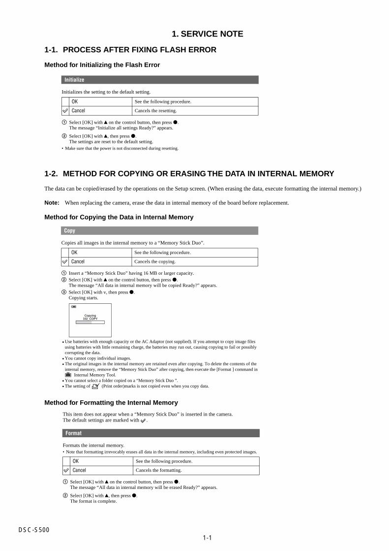
1. SERVICE NOTE
1-1. PROCESS AFTER FIXING FLASH ERROR
Method for Initializing the Flash Error
Initializes the setting to the default setting.
1 Select [OK] with v on the control button, then press z.The message “Initialize all settings Ready?” appears.
2 Select [OK] with v, then press z.The settings are reset to the default setting.
• Make sure that the power is not disconnected during resetting.
Initialize
OK See the following procedure.
Cancel Cancels the resetting.
Copies all images in the internal memory to a “Memory Stick Duo”.
1 Insert a “Memory Stick Duo” having 16 MB or larger capacity.2 Select [OK] with v on the control button, then press z.
The message “All data in internal memory will be copied Ready?” appears.
3 Select [OK] with v, then press z.Copying starts.
Copy
OK See the following procedure.
Cancel Cancels the copying.
Copying102_COPY
Use batteries with enough capacity or the AC Adaptor (not supplied). If you attempt to copy image filesusing batteries with little remaining charge, the batteries may run out, causing copying to fail or possiblycorrupting the data.You cannot copy individual images.The original images in the internal memory are retained even after copying. To delete the contents of theinternal memory, remove the “Memory Stick Duo” after copying, then execute the [Format ] command in Internal Memory Tool.You cannot select a folder copied on a “Memory Stick Duo ”.The setting of (Print order)marks is not copied even when you copy data.
•
••
••
1-2. METHOD FOR COPYING OR ERASING THE DATA IN INTERNAL MEMORY
The data can be copied/erased by the operations on the Setup screen. (When erasing the data, execute formatting the internal memory.)
Note: When replacing the camera, erase the data in internal memory of the board before replacement.
Method for Copying the Data in Internal Memory
Method for Formatting the Internal Memory
This item does not appear when a “Memory Stick Duo” is inserted in the camera.The default settings are marked with .
Formats the internal memory.• Note that formatting irrevocably erases all data in the internal memory, including even protected images.
1 Select [OK] with v on the control button, then press z.The message “All data in internal memory will be erased Ready?” appears.
2 Select [OK] with v, then press z.The format is complete.
Format
OK See the following procedure.
Cancel Cancels the formatting.
2-1DSC-S500
1
2
3
1
1
1
1
2
3
2
4
1
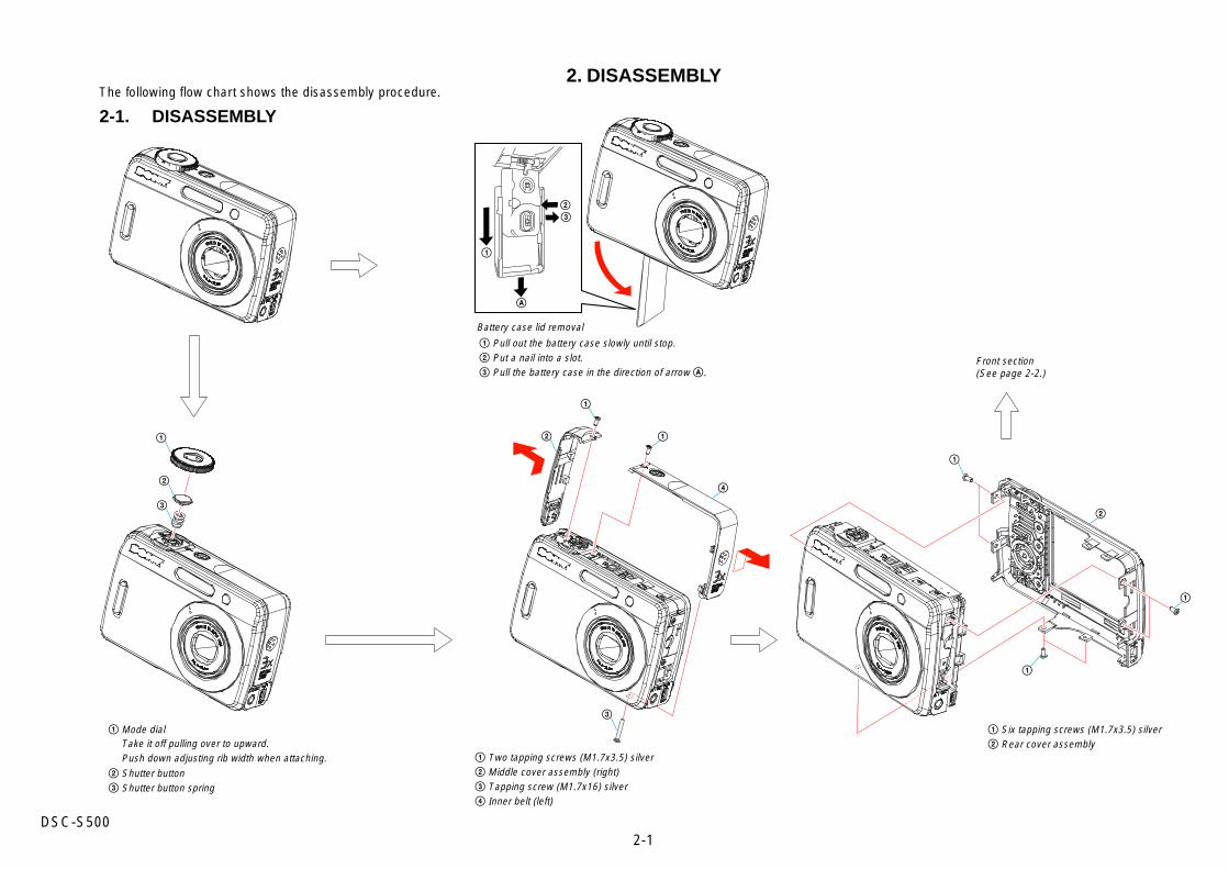
1 Two tapping screws (M1.7x3.5) silver2 Middle cover assembly (right)3 Tapping screw (M1.7x16) silver4 Inner belt (left)
Front section(See page 2-2.)
1 Mode dial
2 Shutter button3 Shutter button spring
1 Six tapping screws (M1.7x3.5) silver2 Rear cover assemblyTake it off pulling over to upward.
Push down adjusting rib width when attaching.
Battery case lid removal
1 Pull out the battery case slowly until stop.2 Put a nail into a slot.3 Pull the battery case in the direction of arrow A.
A
1
23
2. DISASSEMBLY
2-1. DISASSEMBLYThe following flow chart shows the disassembly procedure.
2-2DSC-S500
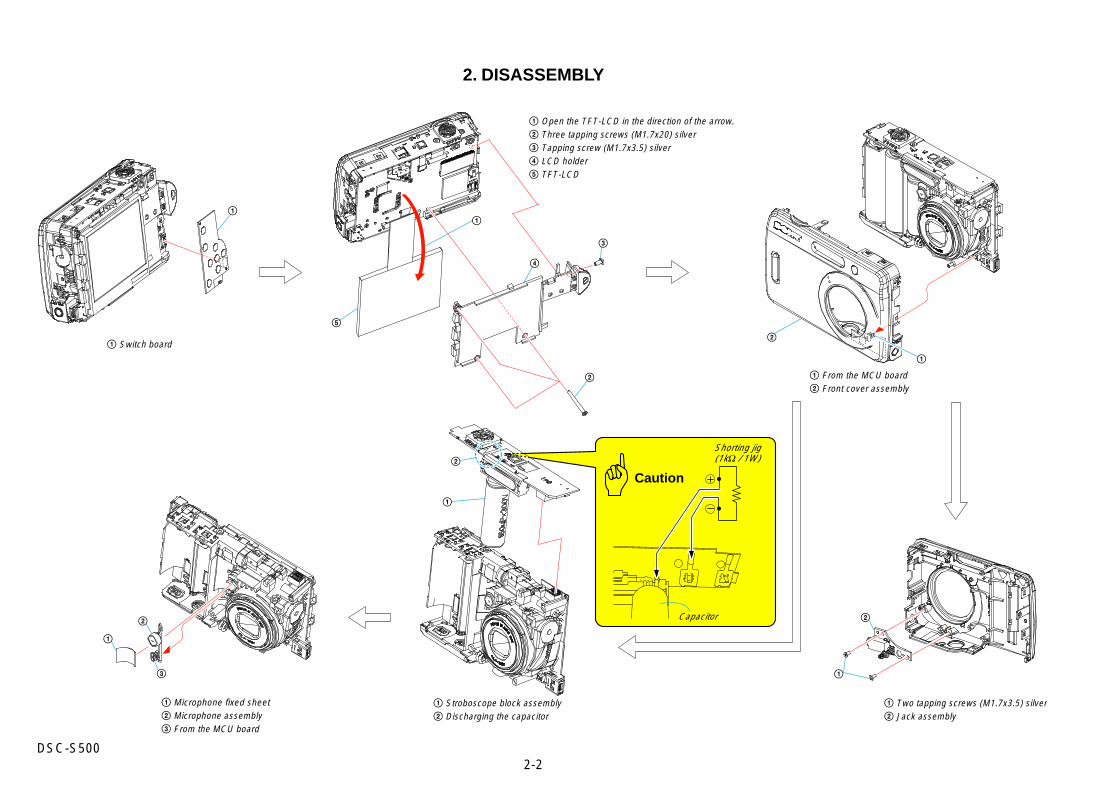
2. DISASSEMBLY
Capacitor
Caution
Shorting jig(1kΩ / 1W)
1 Microphone fixed sheet2 Microphone assembly3 From the MCU board
1 Open the TFT-LCD in the direction of the arrow.2 Three tapping screws (M1.7x20) silver3 Tapping screw (M1.7x3.5) silver4 LCD holder5 TFT-LCD
1 From the MCU board2 Front cover assembly
1 Two tapping screws (M1.7x3.5) silver2 Jack assembly
1 Stroboscope block assembly2 Discharging the capacitor
1 Switch board
1
5
4
2
1
2
3
1
2
1
1
2
3
1
2
3-1DSC-S500
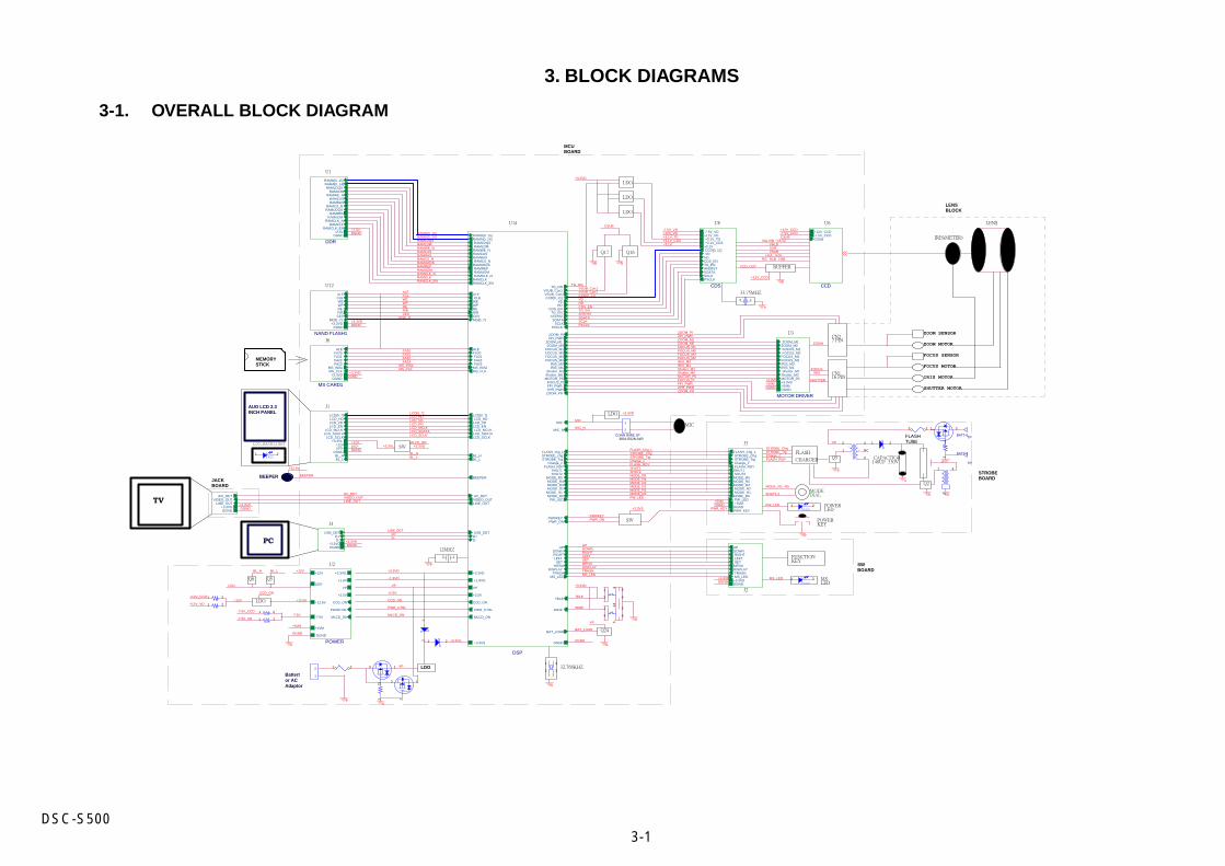
3. BLOCK DIAGRAMS
3-1. OVERALL BLOCK DIAGRAM
CN2
ZOOM MOTOR
FOCUS MOTOR
IRIS MOTOR
SHUTTER MOTOR
CN1
FOCUS SENSOR
ZOOM SENSOR
BUFFER
Q17 Q16
LENS
IRIS(METER)
16 PIN
7 PIN
J1
BEEPER
LCD_BACKLIGHT
12MHZ
32.768KHZ
AUO LCD 2.3 INCH PANEL
TV
PC
MODEDIAL
STROBEBOARD
SWBOARD
CAPACITOR140UF 330V
LDO
LDO
33.75MHZ
Q24
LDO
FLASHTUBE
SW
MIC
LDO
POWERKEY
MEMORYSTICK
U1
U12
J6
SW
Q5Q6
U2
U8 U6
U3
LENSBLOCK
POWERLED
MSLED
FUNCTIONKEY
MCUBOARD
LDO
LDO
JACKBOARD
U14
J4
J3
J2
FLASH
CHARGER Q5
Q2
Battertor ACAdaptor
MS CARD1
MS_INS#
FA20FA21
MS_CLK
FA22FA23
ALE
+3.3VDDGND
POWER
+2.5V
+1.8V
CCD_ON
PWRCTRL
LED-
+5VM
+3.3VD
VP
+12V
DGND
-7.5V MLCD_ON
+12.5V
MODE_R5MODE_R4MODE_R3MODE_R2MODE_R1
MODE_R0
SHUT1SHUT2
FLASH_Chg_LSTROBE_Chg
Charge_cSTROBE_Trg
PW_LED
FLASH_RDY
PWR_KEY
+5VMDGND
VIDEO_OUTA/V_DET
LINE_OUT+3.3VDDGND
DDR
RAMD[0..15]RAMA[0..14]
RAMLDMRAMWE_N
RAMCASRAMRAS
RAMCS_N
RAMLDQS
RAMUDQS
RAMUDMRAMCLK_N
RAMCLKRAMCLK_EN
RAMREF
DGND+2.5V
NAND FLASH1
CLEWEWP
ALE
CE0
RER/B
MD[0..7]+3.3VD
DGND
DSP
RAMD[0..15]RAMA[0..14]
RAMCS_NRAMUDQS
ALECLE
WE
REWP
BAT_LOAD
CE0R/B
CCD[0..11]VDHD
CDS_ENTG_EN
RAMREF
RAMLDM
RAMCASRAMWE_N
RAMRAS
RAMUDM
FOCUS_PI
ZOOM_PR
SHUT1
ZOOM_PI
STROBE_Trg
FOCUS_M0FOCUS_M1
FOCUS_M2FOCUS_M3
ZOOM_M0ZOOM_M1
LCD_HDLCD_VD
VIDEO_OUT
MOTOR_PS
Shutter_M1Shutter_M0
IRIS_M1IRIS_M0
BEEPER
LCD_MCLK
LCD[0..7]
ZPI_PWR
PWR_CTRL
D-D+
DGND
+3.3VD
+1.8VD
LCD_EN
MD[0..7]
SHUT2
VP
LCD_SCLKLCD_SDATA
CCD_ON
Charge_c
ZPR_PWRFPI_PWR
RAMCLK_NRAMCLKRAMCLK_EN
RAMLDQS
FLASH_RDY
MLCD_ON
MODE_R0MODE_R1MODE_R2MODE_R3
LINE_OUT
+2.5V
FLASH_chg_L
AFERST
STROBE_chg
WIDE
MODE_R4MODE_R5
MS_INS#
AV_DET
MS_CLK
TELE
USB_DET
FA20FA21FA22FA23
DOWN
PW_LED
BL_H
TRASH
LEFTRIGHT
PXCLK
BL_L
DISPLAY
UP
SETMENU
SCLK
VSUB_Con1VSUB_Con2
SDATA
MS_LED
+3.3VS
TG_ON
PWRKEYPWR_ON
MIC
MIC_N
ALE
CDS
CCD[0..11]VD
HD
SCLKPXCLK
AFERSTSDATA
CDS_ENTG_EN
+3.1V+3.1V_CDS+3.1V_TG
-7.5V_VD+12V_VD
MOTOR DRIVER
MOTOR_PS
ZOOM_M1ZOOM_M0FOCUS_M1FOCUS_M0
FOCUS_M3FOCUS_M2IRIS_M0IRIS_M1Shutter_M1
Shutter_M0
+5VMDGND
+3.3VD
LEFTRIGHT
UPDOWN
MENUDISPLAYTRASH
SET
MS_LED+3.3VDDGND
CCD
CSUB-7.5V_CCD+12V_CCD
LCD_ENLCD_MCLK
LCD_HD
LCD_SCLKLCD_SDATA
LCD_VD
LCD[0..7]
+3.3VL
LED-DGND
+12V
BL_HBL_L
D+USB_DET
D-+3.3VDDGND
MLCD_ON
MODE_R3
STROBE_Chg
+12.5V
-7.5V
STROBE_Trg
HDVDCCD[0..11]
SDATA
FOCUS_M1
FOCUS_M2
FOCUS_M0
IRIS_M0
FOCUS_M3
ZOOM_M0
IRIS_M1Shutter_M1
LCD[0..7]
+5VM
Charge_cFLASH_RDYSHUT1
MODE_R5
DGND
+12V
ZOOM
FOCUSIRIS
SHUTTER
ZPR_PWRZOOM_PR
ZOOM_PIZPI_PWR
RAMLDM
RAMCAS
RAMA[0..14]
RAMWE_N
RAMUDQSRAMREF
RAMCS_NRAMRAS
RAMUDMRAMCLK_N
RAMCLK_ENRAMCLK
RAMLDQS
PXCLKSCLK
VSUB_Con2
CDS_ENTG_ENAFERST
VIA,VIB ~V4,V2VHLD
VSUBH1A H2A
H1B H2BRG
CCD_OUT
VSUB_Con1ALE
R/B
CLEWE
CE0
RE
FA21FA22FA23
FPI_PWRFOCUS_PI
RAMD[0..15]
LINE_OUT
AV_DET
BEEPER
VIDEO_OUT
PW_LED
MODE_R0 ~R5
SHUT1,2
RIGHT
UP
LEFTSETMENUDISPLAYTRASHMS_LED
DOWN
D+D-
FD[0..7]+3.3VDDGND
+2.5V
+12V
BL_LBL_H
+12V_CCD
+12V_VD
CCD_ON
+12.5V
PWR_CTRL
CCD_ON
+2.5V
+5VMDGND
+3.3VDDGND
+3.3VDDGND
ZOOM_M1
+5VMDGND
+3.3VD
+3.3VD
+3.1V_TG+3.1V_CDS
+12V_CCD
+1.8VD
TELE
WIDE
+3.3VD
VP
DGND
BAT_LOAD
+3.3VS
PWR_ON
MIC
MIC_N
+3.3VD
+3.3VD
DGND
MS_CLK
FA20
+3.3VD
MS_INS#
LCD_HDLCD_VDLCD_ENLCD_MCLK
LCD_SCLKLCD_SDATA
+3.3VL +3.3VDMLCD_ON
DGND
+12VLED-
BL_LBL_H
WP
+3.3VDDGND
-7.5V_CCD
-7.5V_VD
+3.3VS
VP
VPLED-
USB_DET
TG_ON
+12V_VD-7.5V_VD
CSUB
SUB
+12V_CCD-7.5V_CCDCSUB
+3.1V
Shutter_M0MOTOR_PS
MS_LED
PWRKEY
PWR_KEY
SHUT2
PW_LED
MODE_R4
MODE_R2MODE_R1MODE_R0
FLASH_Chg_L STROBE_ChgSTROBE_TrgCharge_cFLASH_RDY
VP
DGND
OFFPAGELEFT-R
3
14
25
6
SP1,P2
1
42
3
NC
RED1 2
1 2
1 2
1 2
1 2
12
12
1
2
2
13
3
1
42
5
6
12
12
1 2
1 3
2
1 2
1 2
GREEN
1 2
41
32
GREEN
1 2
2
13
2
1 3
CONN WIRE 2P3801-E02N-01R
1
2
12
BATT+1TP
BATT-1
TP
12
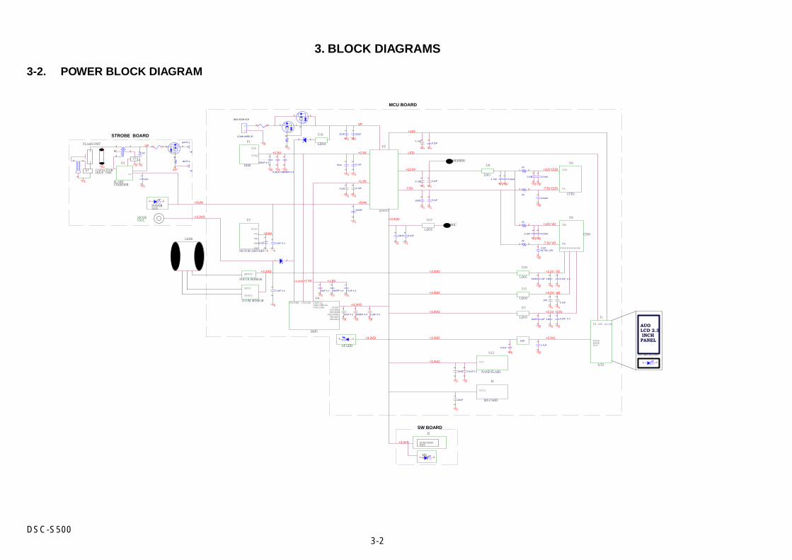
3-2DSC-S500
3. BLOCK DIAGRAMS
3-2. POWER BLOCK DIAGRAM
MIC
STROBE BOARD
BEBBER
VDDPLLVDDUSBPLLVDDCORE
VDDDDR
J2
VDDPVDDDACVDDUSB
VDDSPKRVDDADCVDDAUO
AUOLCD 2.3 INCHPANEL
LCD_BACKLIGHT
PVDDAVDDVCC
FB LED anode
FUNCTIONKEY
AF LED
U8
U2
U12
U2
VDDPWR
U1
Q2
Q5
J6
J1
CAPACITOR140UF 330V
U16
VH
MODEDIAL
VL
ZPIV
AFPIV
ZPRCO
LENS
SW BOARD
PVDD DVDD
FLASHCHARGER
MSLED
U10
U3
FLASH UNIT
PVCC
VCC
VM1
VM2
VM3 AVDD
VDD
VL
VDD
VDDQ
VCC
U11
MCU BOARD
U17
U7
POWERLED
U9
VCC2
U6
U4
VCC
LDO5
DSP1
SW
power1
NAND FLASH
LDO
LCD
CDS1
MS CARD
LDO2
LDO1
LDO3
CCD1
DDR
LDO4
ZOOM SENSOR
FOCUS SENSOR
MOTOR DRIVER1
+12V VD
-7.5V CCD
-7.5V VD
+3.3VD
+3.3VS
+12.5V
+3.3VD
+3.3VD
+3.3VD
+3.3VD
+3.3VD
+2.5V
+3.1V TG
+3.3VD
VP
+12V CCD
+3.3VD
+12V
+3.3VD
+2.5V
+5VM
+3.3VD
+5VM
+3.1V CDS
+3.3VD
+3.1V VD
LED-+2.5V
+1.8V
+5VM
+1.8V
-7.5V
+3.3VL
VP
10UF X 2
12
0.1UF X 5
12
100UF X 4
12
BULE1 2
#01 2
0.1UF
12
1000PF X 4
12
1UF
12
10UF X 2
12
0.1UF X 4
12
22UF
12
47UF12
0.1UF
12
0.01UK
12
#0
1 2
10UF
12
#01 2
12
2.2UK
12
#01 2
2.2UK
12
22UF
12
13
2
0.1UF
12
22UF
12
0.01UK
12
C107#4.7UK_25V
12
CONN WIRE 2P
3801-E02N-01R
1
2
2
131 2
12
0.1UF
12
4.7UK
12
4.7UF
12
0.1UF
12 4.7UK
12
0.01UK
12
RED1 2
22UF
12
0.1UF
12
12
2
1 3
BATT-2
TP
BATT+2
TP
12
2
13
1UF
12
BULE12
22UF
12
0.1UF
12
10UF
12
0.1UF X 2
12
1UF X 3
12
0.1UF X 4
12
10UF
12
0.01UK
12
4.7UK 12
0.1UF
12
+ 100UF
12
SP1,P2
1
4 2
3
NC
0.1UF X 4
12
10UF
12
1 2
BULE1 2
0.01UF X 7
12
10UF
12
1UF X 3
12
0.1UF X 4
12
0.1UF X 4
12
+47UF
12
1000PF X 3
12
1000PF X 5
12
4-1DSC-S500
Ref. No. Part No. Description Ref. No. Part No. Description
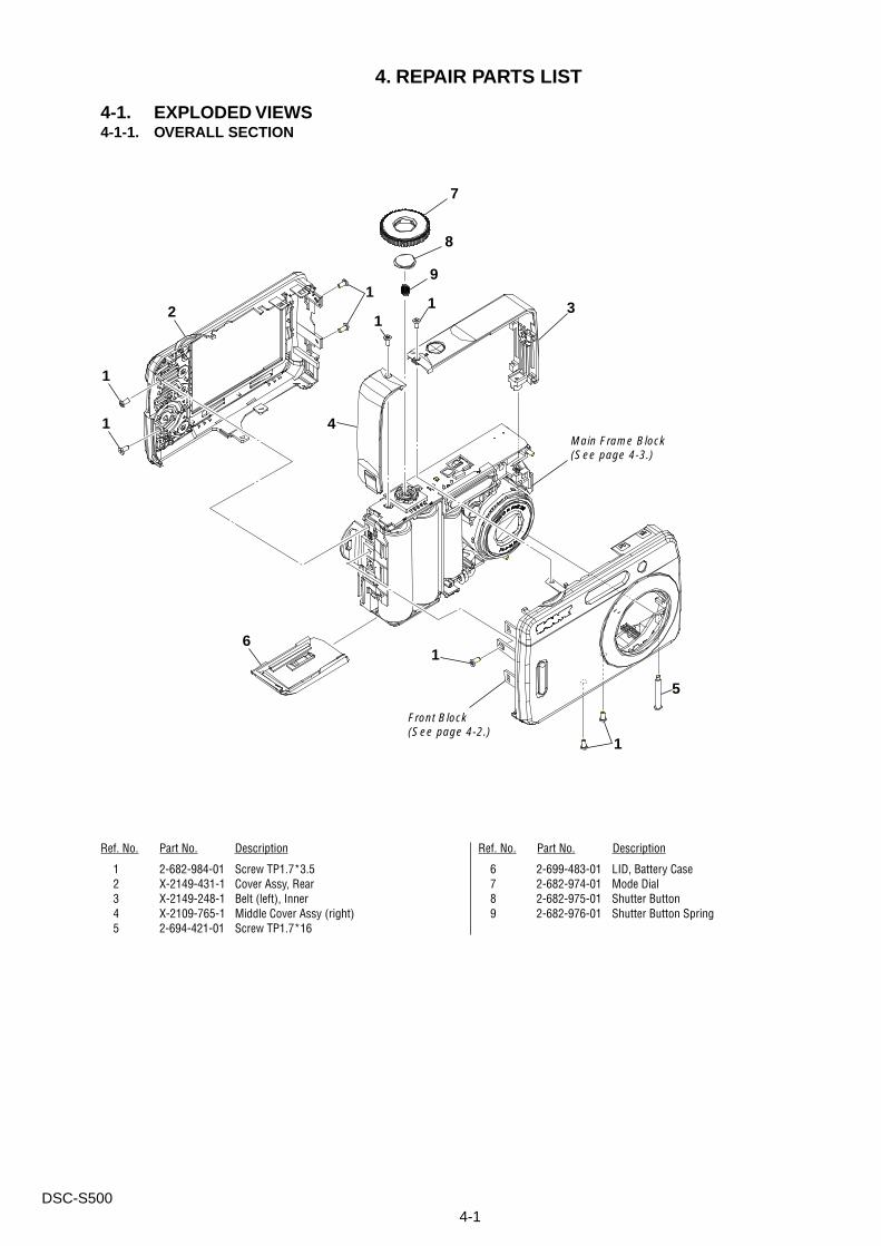
1 2-682-984-01 Screw TP1.7*3.52 X-2149-431-1 Cover Assy, Rear3 X-2149-248-1 Belt (left), Inner4 X-2109-765-1 Middle Cover Assy (right)5 2-694-421-01 Screw TP1.7*16
6 2-699-483-01 LID, Battery Case7 2-682-974-01 Mode Dial8 2-682-975-01 Shutter Button9 2-682-976-01 Shutter Button Spring
4. REPAIR PARTS LIST
4-1. EXPLODED VIEWS4-1-1. OVERALL SECTION
2
1
1
1
6
3
1
11
9
8
7
4
Front Block(See page 4-2.)
1
5
Main Frame Block(See page 4-3.)
4-2DSC-S500
Ref. No. Part No. Description
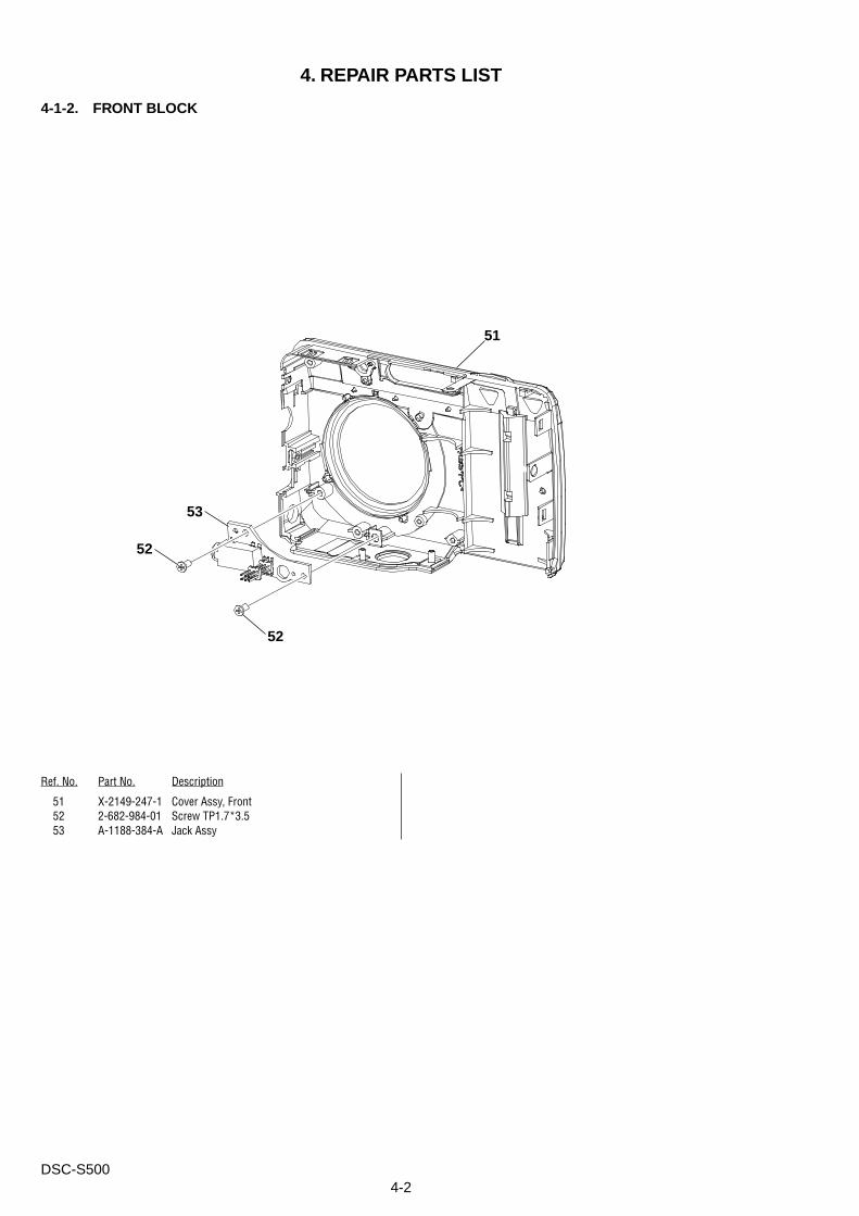
4-1-2. FRONT BLOCK
51 X-2149-247-1 Cover Assy, Front52 2-682-984-01 Screw TP1.7*3.553 A-1188-384-A Jack Assy
4. REPAIR PARTS LIST
51
52
52
53
4-3DSC-S500
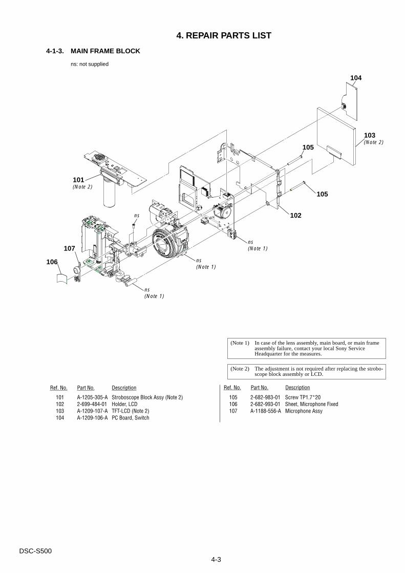
105 2-682-983-01 Screw TP1.7*20106 2-682-993-01 Sheet, Microphone Fixed107 A-1188-556-A Microphone Assy
4-1-3. MAIN FRAME BLOCK
(Note 1) In case of the lens assembly, main board, or main frameassembly failure, contact your local Sony ServiceHeadquarter for the measures.
4. REPAIR PARTS LIST
Ref. No. Part No. Description Ref. No. Part No. Description
101 A-1205-305-A Stroboscope Block Assy (Note 2)102 2-699-484-01 Holder, LCD103 A-1209-107-A TFT-LCD (Note 2)104 A-1209-106-A PC Board, Switch
ns: not supplied
(Note 2) The adjustment is not required after replacing the strobo-scope block assembly or LCD.
105
102
104
103(Note 2)
ns
ns(Note 1)
101(Note 2)
105
106
107
ns(Note 1)
ns(Note 1)
4-4DSC-S500
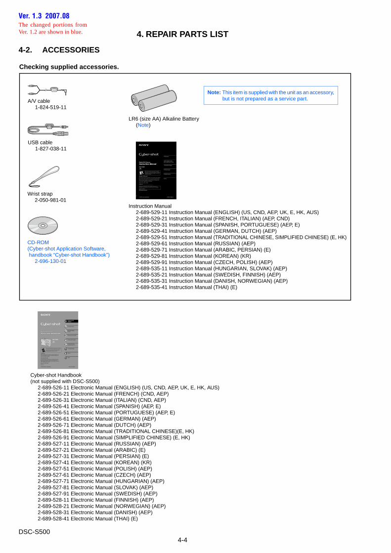
4-2. ACCESSORIES
4. REPAIR PARTS LIST
Checking supplied accessories.
A/V cable 1-824-519-11
Wrist strap 2-050-981-01
CD-ROM(Cyber-shot Application Software, handbook “Cyber-shot Handbook”) 2-696-130-01
USB cable 1-827-038-11
LR6 (size AA) Alkaline Battery (Note)
Instruction Manual 2-689-529-11 Instruction Manual (ENGLISH) (US, CND, AEP, UK, E, HK, AUS) 2-689-529-21 Instruction Manual (FRENCH, ITALIAN) (AEP, CND) 2-689-529-31 Instruction Manual (SPANISH, PORTUGUESE) (AEP, E) 2-689-529-41 Instruction Manual (GERMAN, DUTCH) (AEP) 2-689-529-51 Instruction Manual (TRADITIONAL CHINESE, SIMPLIFIED CHINESE) (E, HK) 2-689-529-61 Instruction Manual (RUSSIAN) (AEP) 2-689-529-71 Instruction Manual (ARABIC, PERSIAN) (E) 2-689-529-81 Instruction Manual (KOREAN) (KR) 2-689-529-91 Instruction Manual (CZECH, POLISH) (AEP) 2-689-535-11 Instruction Manual (HUNGARIAN, SLOVAK) (AEP) 2-689-535-21 Instruction Manual (SWEDISH, FINNISH) (AEP) 2-689-535-31 Instruction Manual (DANISH, NORWEGIAN) (AEP) 2-689-535-41 Instruction Manual (THAI) (E)
Cyber-shot Handbook(not supplied with DSC-S500) 2-689-526-11 Electronic Manual (ENGLISH) (US, CND, AEP, UK, E, HK, AUS) 2-689-526-21 Electronic Manual (FRENCH) (CND, AEP) 2-689-526-31 Electronic Manual (ITALIAN) (CND, AEP) 2-689-526-41 Electronic Manual (SPANISH) (AEP, E) 2-689-526-51 Electronic Manual (PORTUGUESE) (AEP, E) 2-689-526-61 Electronic Manual (GERMAN) (AEP) 2-689-526-71 Electronic Manual (DUTCH) (AEP) 2-689-526-81 Electronic Manual (TRADITIONAL CHINESE)(E, HK) 2-689-526-91 Electronic Manual (SIMPLIFIED CHINESE) (E, HK) 2-689-527-11 Electronic Manual (RUSSIAN) (AEP) 2-689-527-21 Electronic Manual (ARABIC) (E) 2-689-527-31 Electronic Manual (PERSIAN) (E) 2-689-527-41 Electronic Manual (KOREAN) (KR) 2-689-527-51 Electronic Manual (POLISH) (AEP) 2-689-527-61 Electronic Manual (CZECH) (AEP) 2-689-527-71 Electronic Manual (HUNGARIAN) (AEP) 2-689-527-81 Electronic Manual (SLOVAK) (AEP) 2-689-527-91 Electronic Manual (SWEDISH) (AEP) 2-689-528-11 Electronic Manual (FINNISH) (AEP) 2-689-528-21 Electronic Manual (NORWEGIAN) (AEP) 2-689-528-31 Electronic Manual (DANISH) (AEP) 2-689-528-41 Electronic Manual (THAI) (E)
2-689-529-11(1)© 2006 Sony Corporation
Digital Still Camera
Instruction Manual
Owner’s RecordThe model and serial numbers are located on the bottom.Record the serial number in the space provided below.Refer to these numbers whenever you call upon your Sony dealer regarding this product.
Model No. DSC-S500
Serial No. ___________________
http://www.sony.net/
Before operating the unit, please read this manual and “Cyber-shot Handbook” (PDF) on CD-ROM (supplied) thoroughly, and retain it for future reference.
Additional information on this product and answers to
frequently asked questions can be found at our Customer
Support Website.
DSC-S500
Preparation
Shoot images easily (Auto adjustment mode)
View/delete images
Printing images
Troubleshooting
Others
2-689-526-11(1)© 2006 Sony Corporation
Digital Still Camera
Cyber-shot HandbookDigital Still Camera
Cyber-shot Handbook
DSC-S500
ìInstruction Manualî (separate volume)
Explains the set-up and basic operations for shooting/playback with your camera.
Digital Still Camera
HandbookBefore operating the unit, please read this handbook and ìI nstruction Manualî ( separate volume) thoroughly, and retain it for future reference.
Ownerís RecordThe model and serial numbers are located on the bottom. Record the serial number in the space provided below. Refer to these numbers whenever you call upon your Sony dealer regarding this product.
Model No. DSC-S500
Serial No. ___________________________
Enjoying the camera
Using the menu
Using the Setup screen
Using your computer
Printing still images
Connecting your camera to your TV
Troubleshooting
Others
Index
Note: This item is supplied with the unit as an accessory,but is not prepared as a service part.
Ver. 1.3 2007.08The changed portions fromVer. 1.2 are shown in blue.
L4C57
U16
C18
D4
D5
C189
J8
R164
Q24
R163
C163
C47
R141
Q7 R49
R47
C197
Q29
C402F1
C401
J7
C7 C6 C15
C8 C5 R6
C4
R38
R10
4
R14
3
R41
1R
142
C19
8
C15
8
C98
C9
U17
R41
2
C40
5
R10
5
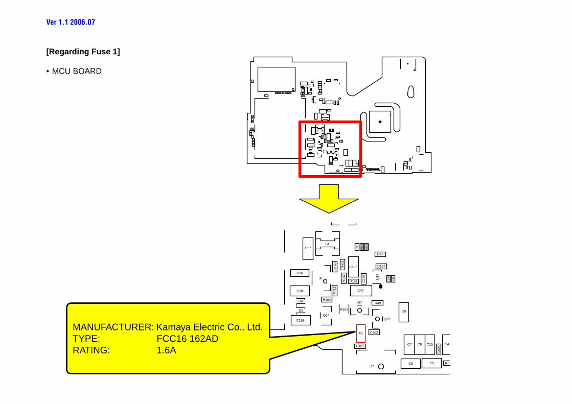
MANUFACTURER: Kamaya Electric Co., Ltd.TYPE: FCC16 162ADRATING: 1.6A
[Regarding Fuse 1]
• MCU BOARD
Ver 1.1 2006.07
SW2
Q3F1
TP5Q4
SW1
R15
R13
LED
1
TP1
SW2
Q3F1
TP5
Q4SW1
R15
R13
LED
1TP1
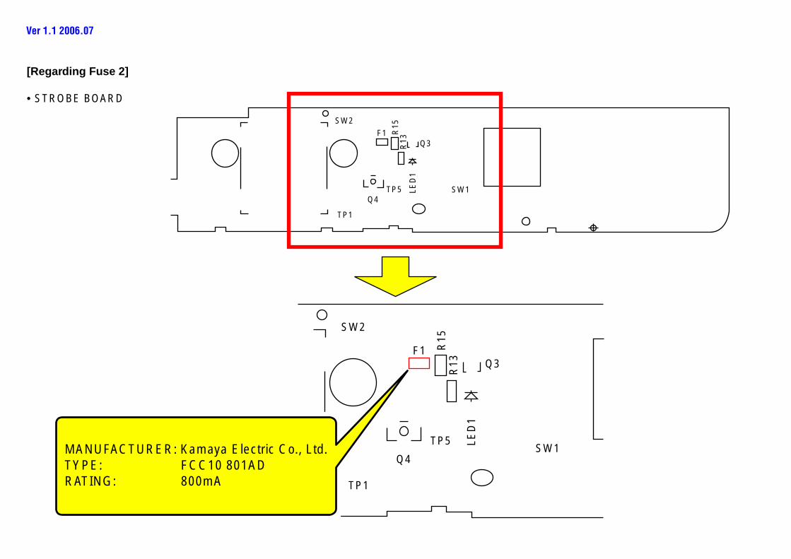
MANUFACTURER: Kamaya Electric Co., Ltd.TYPE: FCC10 801ADRATING: 800mA
[Regarding Fuse 2]
• STROBE BOARD
Ver 1.1 2006.07
SERVICE MANUAL
DSC-S500Sony EMCS Co.
Ver. 1.3 2007.08
SUPPLEMENT-2File this supplement with the service manual.
(DI07-052)
• Addition of Repair Parts• Revision of Accessories
US ModelCanadian Model
AEP ModelUK Model
E ModelAustralian Model
Hong Kong ModelKorea Model
DSC-S500
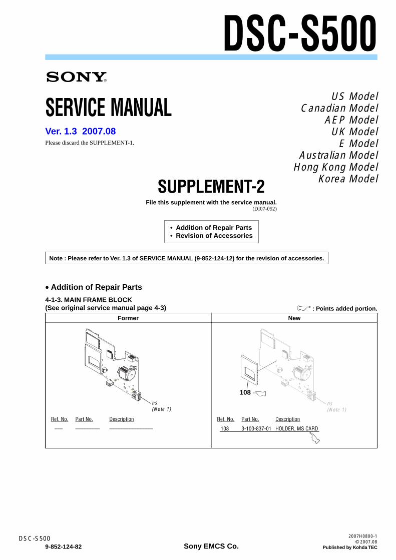
• Addition of Repair Parts
4-1-3. MAIN FRAME BLOCK(See original service manual page 4-3)
Former New
ns(Note 1)
108
ns(Note 1)
––– ––––––––– ––––––––––––––––
Ref. No. Part No. Description
108 3-100-837-01 HOLDER, MS CARD
Ref. No. Part No. Description
)
& : Points added portion.
Please discard the SUPPLEMENT-1.
Note : Please refer to Ver. 1.3 of SERVICE MANUAL (9-852-124-12) for the revision of accessories.
9-852-124-82
2007H0800-1© 2007.08
Published by Kohda TEC
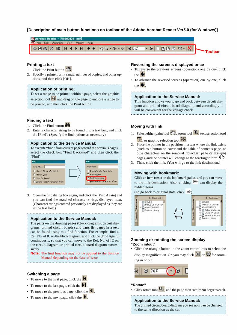
[Description of main button functions on toolbar of the Adobe Acrobat Reader Ver5.0 (for Windows)]
Printing a text1. Click the Print button .2. Specify a printer, print range, number of copies, and other op-
tions, and then click [OK].
Application of printing:To set a range to be printed within a page, select the graphic
selection tool and drag on the page to enclose a range tobe printed, and then click the Print button.
Finding a text1. Click the Find button .2. Enter a character string to be found into a text box, and click
the [Find]. (Specify the find options as necessary)
Application to the Service Manual:To execute “find” from current page toward the previous pages,select the check box “Find Backward” and then click the“Find”.
3. Open the find dialog box again, and click the [Find Again] andyou can find the matched character strings displayed next.(Character strings entered previously are displayed as they arein the text box.)
Application to the Service Manual:The parts on the drawing pages (block diagrams, circuit dia-grams, printed circuit boards) and parts list pages in a textcan be found using this find function. For example, find aRef. No. of IC on the block diagram, and click the [Find Again]continuously, so that you can move to the Ref. No. of IC onthe circuit diagram or printed circuit board diagram succes-sively.Note: The find function may not be applied to the Service
Manual depending on the date of issue.
Switching a page• To move to the first page, click the .
• To move to the last page, click the .
• To move to the previous page, click the .
• To move to the next page, click the .
Reversing the screens displayed once• To reverse the previous screens (operation) one by one, click
the .
• To advance the reversed screens (operation) one by one, click
the .
Application to the Service Manual:This function allows you to go and back between circuit dia-gram and printed circuit board diagram, and accordingly itwill be convenient for the voltage check.
Moving with link
1. Select either palm tool , zoom tool , text selection tool
, or graphic selection tool .2. Place the pointer in the position in a text where the link exists
(such as a button on cover and the table of contents page, orblue characters on the removal flowchart page or drawingpage), and the pointer will change to the forefinger form .
3. Then, click the link. (You will go to the link destination.)
Moving with bookmark:Click an item (text) on the bookmark pallet, and you can moveto the link destination. Also, clicking can display thehidden items.(To go back to original state, click )
Zooming or rotating the screen display“Zoom in/out”• Click the triangle button in the zoom control box to select the
display magnification. Or, you may click or for zoom-
ing in or out.
“Rotate”• Click rotate tool , and the page then rotates 90 degrees each.
Application to the Service Manual:The printed circuit board diagram you see now can be changedto the same direction as the set.
Toolbar
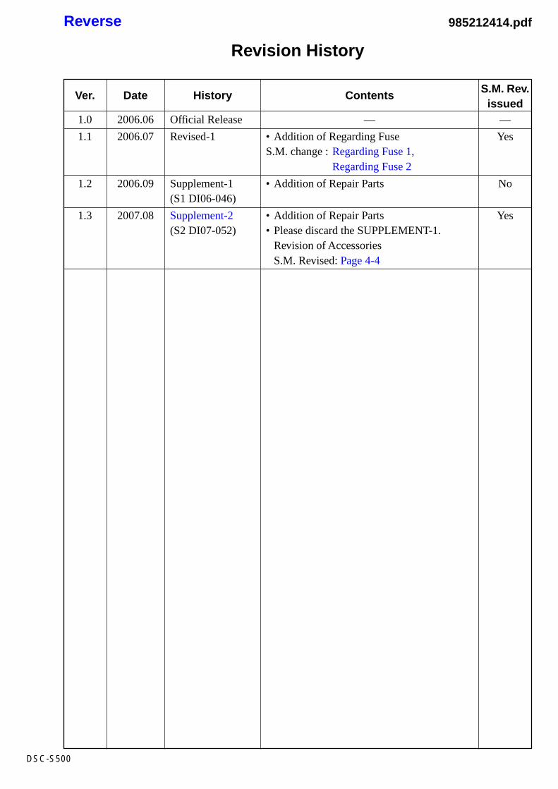
Revision History
Reverse
DSC-S500
Ver.
1.0
1.1
1.2
1.3
Date
2006.06
2006.07
2006.09
2007.08
History
Official Release
Revised-1
Supplement-1(S1 DI06-046)
Supplement-2(S2 DI07-052)
Contents
—
• Addition of Regarding FuseS.M. change : Regarding Fuse 1,
Regarding Fuse 2
• Addition of Repair Parts
• Addition of Repair Parts• Please discard the SUPPLEMENT-1.
Revision of AccessoriesS.M. Revised: Page 4-4
S.M. Rev.issued
—
Yes
No
Yes
985212414.pdf