Embed Size (px)
Citation preview
Aur 0001 : General Mechanical Requirements
© Copyright – Aurecon South Africa (Pty) Ltd Page 1
SPECIFICATION: Aur 0001
GENERAL MECHANICAL REQUIREMENTS
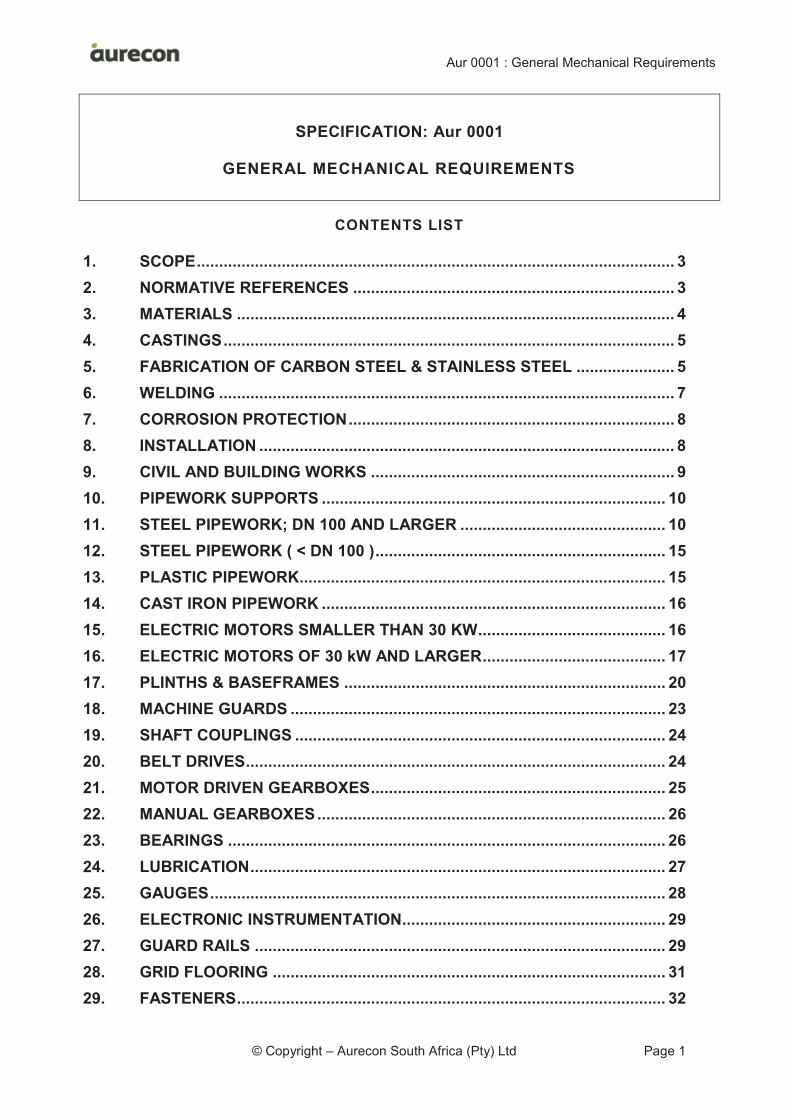
CONTENTS LIST
SCOPE ........................................................................................................... 3 1.
NORMATIVE REFERENCES ........................................................................ 3 2.
MATERIALS .................................................................................................. 4 3.
CASTINGS ..................................................................................................... 5 4.
FABRICATION OF CARBON STEEL & STAINLESS STEEL ...................... 5 5.
WELDING ...................................................................................................... 7 6.
CORROSION PROTECTION ......................................................................... 8 7.
INSTALLATION ............................................................................................. 8 8.
CIVIL AND BUILDING WORKS .................................................................... 9 9.
PIPEWORK SUPPORTS ............................................................................. 10 10.
STEEL PIPEWORK; DN 100 AND LARGER .............................................. 10 11.
STEEL PIPEWORK ( < DN 100 ) ................................................................. 15 12.
PLASTIC PIPEWORK .................................................................................. 15 13.
CAST IRON PIPEWORK ............................................................................. 16 14.
ELECTRIC MOTORS SMALLER THAN 30 KW .......................................... 16 15.
ELECTRIC MOTORS OF 30 kW AND LARGER ......................................... 17 16.
PLINTHS & BASEFRAMES ........................................................................ 20 17.
MACHINE GUARDS .................................................................................... 23 18.
SHAFT COUPLINGS ................................................................................... 24 19.
BELT DRIVES .............................................................................................. 24 20.
MOTOR DRIVEN GEARBOXES .................................................................. 25 21.
MANUAL GEARBOXES .............................................................................. 26 22.
BEARINGS .................................................................................................. 26 23.
LUBRICATION ............................................................................................. 27 24.
GAUGES ...................................................................................................... 28 25.
ELECTRONIC INSTRUMENTATION........................................................... 29 26.
GUARD RAILS ............................................................................................ 29 27.
GRID FLOORING ........................................................................................ 31 28.
FASTENERS ................................................................................................ 32 29.
Aur 0001 : General Mechanical Requirements
© Copyright – Aurecon South Africa (Pty) Ltd Page 2
MACHINE VIBRATION ................................................................................ 33 30.
NOISE CONTROL........................................................................................ 34 31.
THERMAL LAGGING .................................................................................. 34 32.
SPARES ....................................................................................................... 35 33.
SIGNAGE ..................................................................................................... 35 34.
Aur 0001 : General Mechanical Requirements
© Copyright – Aurecon South Africa (Pty) Ltd Page 3
SCOPE 1.
Aur 0001 specifies general technical requirements for mechanical engineering projects in which
the Contractor is responsible for the detailed design.
NORMATIVE REFERENCES 2.
Where this specification is required for a project, the following documents shall, inter alia, form
part of the Contract Document:
a) Amendments, Additions and Detailed Requirements (Aur 0001).
b) Aur 0003: General Corrosion Protection for Pipelines, Water and Waste Water Works.
c) Aur 7001: Design and Manufacture of Medium Pressure Steel Specials.
d) Aur 7024: Pipe Supports.
Equipment, materials and operational methods shall comply with the latest edition of relevant
national and/or international standards.
The following South African National Standards are referred to in this specification:
· SANS 200
· SANS 936/7
· SANS 989/992
· SANS 1034
· SANS 1062
· SANS 1123
· SANS 1186
· SANS 1200H
· SANS 1465
· SANS 1700
· SANS 1804
· SANS 10044
· SANS 10104
· SANS 10160
· SANS 10108
· SANS 15874
· SANS 50025
· SANS 60034-5
· SANS 61241
· SANS/ISO 4427
The following British Standards are referred to in this specification:
· BS 970
· BS 1400
· BS 1452
· BS 1490
Aur 0001 : General Mechanical Requirements
© Copyright – Aurecon South Africa (Pty) Ltd Page 4
· BS 2035
· BS 2789
· BS 3100
· BS 3790
· BS 4515
· BS 4872
· BS 7854
· BS EN 681
· BS EN 1092
· BS EN ISO 23936
The following ISO standards are referred to in this specification:
· ISO 4184
· ISO 10816
MATERIALS 3.
3.1 GENERALLY
All materials used in the manufacture and construction of plant and equipment shall be new,
unused and shall be the best of their respective kinds. The Contractor shall ensure that the
materials are selected in accordance with the best engineering practice to suit the working
conditions and the extremely corrosive environment.
3.2 STEEL
Structural steel shall comply with the requirements of SANS 50025 for grade S 355 JR or for
grade S 355 JO and shall be legibly marked with the maker's name or trade mark and
identification marks.
3.3 STAINLESS STEEL
The grade of stainless steel to be used shall be as specified. Unless otherwise specified, rolled
material shall be supplied with a matt, annealed and pickled or otherwise de-scaled surface
finish. For wrought steels, the equivalent BS 970 grade may in each case be used.
A manufacturer's test certificate shall be provided for each batch of stainless steel giving details
of the material analysis and any mechanical tests carried out on the material. Each stainless
steel item supplied shall be clearly and permanently marked with the grade of stainless steel
and cross referenced to the applicable test certificate.
Where grades EN Grade 1.4401 (316) and EN Grade 1.4301 (304) are specified, these shall be
taken synonymously with the low carbon grades for welding.
3.4 3CR12
This is the titanium stabilised, 12 % chrome steel as produced by Columbus Stainless, South
Africa.
3CR12 shall always be supplied with an annealed and pickled finish. 3CR12, in cases where it
is to be coated, shall be suitably abrasive blasted to ensure adherence of the prime coat.
Aur 0001 : General Mechanical Requirements
© Copyright – Aurecon South Africa (Pty) Ltd Page 5
3.5 PLASTICS
Thermoplastics and fibre reinforced polymers shall be UV resistant, have adequate tensile
strength and high impact strength and generally suit the application.
PVC is regarded as too brittle and shall not be used unless called for in this Specification or
approved in writing by the Engineer before supply.
CASTINGS 4.
Castings shall comply with the relevant South African or international standard for the material
used, including the following:
Grey Cast Iron SANS 1034; BS 1452
S. G. Iron SANS 936/7; BS 2789
Steel (General Purpose) SANS 1465; BS 3100
Aluminium SANS 989/992; BS 1490
Stainless Steel DIN 17 445
Copper and Copper Alloy SANS 200; BS 1400
Castings shall be clean and sound and shall be neatly fettled and dressed. Surfaces shall be
smooth and irregularities caused by mould washaways, and the presence of porosity, inclusions
and sharp edges will not be tolerated. Areas under bolt heads, nuts and washers, shall be
machined or spot faced to ensure a flat and smooth pressure bearing area, and sufficient space
shall be provided for the use of ring or socket spanners.
All pressure retaining castings shall be hydrostatically tested to not less than 1,5 times the
maximum working pressure after machining and shall be pressure tight.
No repairs shall be undertaken to castings without the written permission of the Engineer. Cast
iron castings shall not be welded.
Castings shall be heat treated to provide optimum corrosion resistance and toughness
combined with reasonable machinability. In particular stainless steel castings shall be heat
treated so as to ensure that all carbides are in solution, to ensure optimum grain size, and to
provide maximum corrosion resistance.
The Contractor shall provide a test certificate for each casting or batch of castings, except for
those made of grey cast iron, giving details of the material analysis, the heat treatment and any
mechanical tests carried out.
FABRICATION OF CARBON STEEL & STAINLESS STEEL 5.
5.1 GENERAL
Steelwork shall generally be constructed, fabricated and erected in accordance with the
applicable requirements of SANS 1200 H.
Welding shall comply with the clause “Welding”.
Aur 0001 : General Mechanical Requirements
© Copyright – Aurecon South Africa (Pty) Ltd Page 6
Sharp edges, pits, inclusions, weld spatter, undercuts, indentations or other surface defects are
not acceptable.
Edges shall be rounded to a radius of at least 2 mm.
Designs shall avoid inaccessible pockets and hollows.
Sharp edges on items fabricated from thin sheets will not be acceptable and sharp edges shall
preferably be avoided by good design.
Inspection of fabrications shall generally be done after fabrication is complete.
5.2 CARBON STEELS
Structural steelwork shall be of grade S 355 JR or of grade S 355 JO in accordance with
SANS 50025.
The requirements of the Hot Dip Galvaniser’s Association of South Africa shall be complied with
if the item is to be hot-dip galvanised. Designs shall provide proper access for safe and
complete entry of the molten zinc into open spaces so that subsequent drilling at the
galvaniser’s yard is avoided.
Surfaces to be coated shall be accessible by blast and spray equipment. Inaccessible pockets,
such as bad weld profile as well as hollow structures, are unacceptable and the angle of impact
of blast material and sprayed coatings shall not be less than 45 degrees. Edges shall be
rounded for safety reasons and also to be suitable for the coating system to be applied.
5.3 AUSTENITIC STAINLESS STEELS
Fabrication of austenitic stainless steels shall comply with the recommendations in "The
Stainless Steel User Manual" issued by Columbus Stainless. Compliance with publications from
equivalent authorities will be acceptable.
Stainless steel fabricators shall use permanently dedicated storage and fabrication areas and
shall use machines, tools and handling equipment which are suited and permanently dedicated
to this type of material.
Fabrications shall be pickled and passivated over their full surface to achieve an even colour. If
grinding is required before pickling, the final grinding shall be done with a fine disc in order to
remove coarse grinding marks.
5.4 3CR12
Fabrication of 3CR12 shall comply with the requirements for austenitic stainless steels except
that the recommendations in "The 3CR12 Fabrication Guide" issued by Columbus Stainless
shall be used. Compliance with publications from equivalent authorities will be acceptable.
5.5 DUPLEX AND HIGHLY ALLOYED STAINLESS STEELS
Fabrication of duplex, super austenitic and other highly alloyed stainless steels shall follow the
metal producer’s own guidelines.
Welding of duplex stainless steel pipework shall be in accordance with BS 4515 Part 2 or
equivalent.
Aur 0001 : General Mechanical Requirements
© Copyright – Aurecon South Africa (Pty) Ltd Page 7
WELDING 6.
6.1 STANDARDS
Standards complying with good modern practice, and acceptable to the Engineer, shall be
adopted and the recommendations of the SAIW are acceptable in this respect.
Welders shall be experienced artisans approved in accordance with BS 4872 or equivalent.
6.2 CONTINUOUS WELDING AND ELIMINATION OF CREVICES
Welding shall be continuous on all sides of any joint. Designs which do not allow this shall be
re-designed.
Crevices, including those arising from welding on one side only, shall be eliminated. This
requirement applies to the welding of all metals and welding procedure shall be designed to
prevent unacceptable deformation.
Welds which are only accessible from one side shall be prepared so that the root run provides
an acceptable profile and prevents the formation of crevices. Pipework shall be designed so
that such welds can be inspected and, where applicable, pickled and passivated.
In special cases only, non-continuous welding might be approved in writing by the Engineer.
The resulting crevices shall be sealed with a two part solvent free epoxy which can be applied at
thicknesses of up to 600 μm and above such as Sigmaline 523 or Corrocoat Zip E or
Sigmacover 1000 or equivalent.
6.3 WELD APPEARANCE
Welding shall be free of blowholes, projections, pinholes, splatter and undercuts and all welding
flux, weld spatter and other sharp imperfections shall be removed. Weld beads with a surface
irregularity exceeding 3 mm or with sharp crests having a radius under 2 mm shall be ground.
6.4 SITE WELDING
Site welding shall be kept to a minimum and shall only be undertaken with the approval of the
Engineer.
6.5 WELDING OF STAINLESS STEEL AND 3CR12 – ADDITIONAL REQUIREMENTS
Fabrication of austenitic stainless steels and 3CR12 shall comply with the recommendations in
"The Stainless Steel User Manual", "The 3CR12 Fabrication Guide" and the general welding
requirements in “Pocket Guide – Stainless Steels” issued by Columbus Stainless. Compliance
with publications from equivalent authorities will be acceptable.
Stainless steels to be welded shall be of the low carbon grade; e.g. 1.4306 rather than 1.4301
and 1.4404 rather than 1.4401.
The welding rods used shall be the most suitable for the metal and purpose.
Only welders experienced with welding stainless materials shall be used.
Welds which are accessible from only one side shall be executed in a manner to prevent heat
tint or shall be post-weld treated in order to remove all traces of heat tint.
Type 309 stainless steel welding rods shall be used for welding 3CR12 unless otherwise
approved in writing. 3CR12 shall be welded as recommended in "The 3CR12 Fabrication
Guide" issued by Columbus Stainless.
Aur 0001 : General Mechanical Requirements
© Copyright – Aurecon South Africa (Pty) Ltd Page 8
All possible steps shall be taken to ensure maximum corrosion resistance and strength of the
welds and welded material. Special care shall be taken to avoid prolonged heating. Welds shall
be passivated. Discolouration and steel contamination must be removed by pickling or electro
cleaning as approved by the Engineer but should rather be avoided by taking the appropriate
measures.
6.6 INSPECTIONS
The Contractor shall arrange for all fabrications to be inspected by the Engineer prior to
transport from the fabrication workshop.
CORROSION PROTECTION 7.
7.1 GENERAL
Corrosion protection shall comply with Aur 0003.
7.2 SYSTEMS
The Contractor shall propose corrosion protection systems to the Engineer for review.
The preferred system for structural steelwork and gantries is hot-dip galvanised carbon steel.
The preferred system for cranes is hot metal zinc spray and seal.
The preferred system for pipework internals is a solids containing barrier coating with a dry film
thickness of not less than 800 microns.
The preferred system for guard rails, grid flooring, trench covers, stairways and ladders is
hot-dip galvanised carbon steel (unless stainless steel is called for in the project specifications).
The preferred system for clarifier bridges and other carbon steel structures above water bodies
is epoxy coated 3CR12 or hot-dip galvanised and painted carbon steel or hot metal zinc sprayed
and sealed carbon steel.
7.3 STAINLESS STEEL
Stainless steel pipework which is in contact with pipework or valve of other materials shall be
provided with an internal coat in order to provide an electrical barrier between the stainless steel
and the fluid such as 70 microns of Sigmacover 280 or equivalent. This requirement applies to
puddle pipes which are cast into concrete.
The coat shall extend over flange faces.
Stainless steel valves, strainers and other items of equipment shall be similarly coated.
INSTALLATION 8.
8.1 GENERAL
The Works shall comply with the following:
Aur 0001 : General Mechanical Requirements
© Copyright – Aurecon South Africa (Pty) Ltd Page 9
a) When erected and installed, the plant and equipment shall be of neat and workmanlike appearance, solidly and evenly supported, true to line, level, plumb and in proper working order.
b) The Contractor shall provide all foundation bolts, supports, hangers, brackets, etc. required for the support and fixing of equipment.
c) The Contractor is responsible for grouting work associated with the equipment and pipework to be provided in terms of the Contract.
d) The use of more than three shims in the alignment of equipment will not be permitted. Machined spacers shall be prepared where necessary. Shims and spacers shall be of a corrosion resistant material such as stainless steel.
e) Corrosion protection requirements shall be carefully attended to and the requirements of Aur 0003 must be noted. All mating faces must be coated before and sealed after assembly.
f) A small amount of a nickel based, anti-seize compound shall be applied along the full length of fastener threads before the nut is applied.
g) Crevices which are formed between two metal surfaces shall, prior to final fastening, be filled with a suitable formable packing, Denso tape or equivalent, or with a suitable mastic or sealant.
8.2 ALIGNMENT OF SHAFTS
Shafts for drives with an output above 150 kW shall be aligned to the driven shaft as follows:
a) Final alignment shall be done after installation and before commissioning and shall be checked in the presence of and to the approval of the Engineer. Alignment shall be sufficiently accurate to ensure that no initial pre-load is placed on the shaft coupling.
b) Each motor shall be aligned to its pump by alignment specialists using laser aligning equipment with real time computer display.
c) The use of pourable epoxy resin chocks (Epocast 36, Chockfast or equivalent) shall be acceptable. If pourable chocks are used, the baseframe feet do not have to be machined but each machine foot shall be provided with a screw for vertical alignment. The chock thickness shall not be less than 20 mm.
CIVIL AND BUILDING WORKS 9.
9.1 GENERAL DUTIES
The Contractor shall be responsible for grouting pipework required to pass through walls, for all
equipment grouting work, anchoring of equipment and closing of apertures associated with
equipment to be provided in terms of this Contract.
The Contractor’s Documents shall indicate the civil and building details required to
accommodate the equipment installation; subject to and in accordance with any details shown
on the drawings provided by the Employer. These details shall include plinths, foundation
blocks, rebates, pockets, sleeve ducts, holes, thrust blocks, anchor fasteners and
openings/box-outs for pipework passing through walls.
The Contractor shall inspect and check the related structures constructed by others for accuracy
and suitability of construction and for conformance with the Contractor's documents before
commencing installation and construction. No payments shall be allowed for additional costs to
the Contractor resulting from a failure to check such works timeously or a failure to provide the
related information in Contractor’s Documents timeously.
Aur 0001 : General Mechanical Requirements
© Copyright – Aurecon South Africa (Pty) Ltd Page 10
9.2 CIVIL CONTRACTOR’S WORK
The main civil and building works will be completed by others and will be mostly completed
when the Contractor is granted access to the Site.
9.3 PUDDLE PIPES
The Contractor shall install puddle pipes required by the design into concrete structures unless
otherwise specified. For this purpose, the Contractor shall provide the details of box-outs
required in the structure to the Engineer. Puddle flanges shall be of the same dimensions as
standard flanges and the box-out shall be designed accordingly and with allowance for civil
tolerances of + 40 mm.
The structure will be constructed by others and, if required, it will be tested for water tightness by
the Engineer before handover to the Contractor by temporary closure of the box-outs.
Upon receiving access to the Site, the Contractor shall install the pipework and shall grout the
puddle pipes into the structure using a suitable non-shrink grout to the approval of the Engineer.
The Contractor shall provide a water tight installation and shall be responsible for rectifying any
leakage at the puddle pipe.
9.4 BASEFRAMES, PIPE SUPPORTS, ETC.
The design requirements for baseframes and pipework supports are specified elsewhere in
Aur 0001.
The Contractor shall be responsible for grouting of baseframes, pipe supports, plinths, etc.
required for installation of the equipment and this includes any metallic structure which is
mounted onto a concrete surface.
The method proposed for anchoring baseframes, pipe supports, etc. to concrete shall be
submitted to the Engineer for approval and shall incorporate the details of the grout proposed.
The material used for grouting shall be a non-shrink, cementitious grout such as ABE
Duragrout 1000, or equivalent. ABE Epidermix 324, or equivalent, is acceptable if an epoxy
grout is required.
The design and grouting shall eliminate collection points for water or dirt.
If called for by the Engineer, the initial grouting shall be overseen by the grout supplier's
technical representative.
Grout shall be applied only after each anchor fastener has been tested for integrity.
PIPEWORK SUPPORTS 10.
Supports for steel pipework and for plastic pipework shall comply with Aur 7024.
STEEL PIPEWORK; DN 100 AND LARGER 11.
11.1 GENERAL
This clause applies to carbon steel pipework and to stainless steel pipework.
Aur 0001 : General Mechanical Requirements
© Copyright – Aurecon South Africa (Pty) Ltd Page 11
Steel pipework which is DN 100 or larger shall comply generally with Aur 7001: Design and
Manufacture of Medium Pressure Steel Specials.
The remainder of this clause specifies additional requirements for pipework associated with
equipment installations.
11.2 PIPEWORK CONSTRUCTION AND CONFIGURATION
Pipework shall be joined using bolted flanges.
Stainless steel and 3CR12 pipes shall be to ASTM A312, ANSI B36.19 or ANSI B36.10 or
equivalent.
Pipes and fittings shall be neatly installed, straight to line and level and adequately supported.
Pipework shall be supported above floor level on supports, racks or wall mounted and shall not
be installed directly on the floor.
Pipework shall be configured and shall be provided with couplings and/or bends to allow easy
dismantling and disassembly of all pipework without damage to the pipework or pipe supports.
Provision shall be made for draining all sections of pipework.
Provision shall be made for venting high points of pipework.
Valves shall be mounted in horizontal pipework unless this is not feasible.
Pipework shall be correctly anchored to withstand thrust.
If the physical configuration does not provide axial restraint of pipework couplings, then these
couplings shall be provided with thrust restraints.
Bends shall preferably be of the long radius type. 90 degree “lobster back bends” shall have a
minimum of five segments. Each flange shall be perpendicular to the segment to which it is
welded.
Convergences shall preferably be of swept tee formation rather than tee pieces.
11.3 PUMP SUCTION PIPEWORK
Two mechanical couplings or one rubber tyre type coupling shall be provided on each pump’s
suction pipework.
Pump suction pipework shall comply with good hydraulic design.
The suction manifold/pump leg bifurcation shall be of swept tee formation if the speed of flow
within the leg at that point is one metres per second or higher. If this flow speed within the leg at
that point is lower than one metre per second, the bifurcation may be of a normal tee formation.
The pipework on the suction side of pumps shall be sized to ensure that the flow speed is no
higher than 1,5 m/s.
High points shall be avoided in positions where the flow speed is below one metres per second.
Suction pipework shall be level or shall slope upwards toward the pump.
Air leaks shall be prevented.
Flow straighteners shall not be used if there is a probability that the straightener will capture
solids.
Aur 0001 : General Mechanical Requirements
© Copyright – Aurecon South Africa (Pty) Ltd Page 12
11.4 PUMP DISCHARGE PIPEWORK
Two mechanical couplings or one rubber tyre type coupling shall be provided on each pump’s
discharge pipework.
11.5 REDUCERS
Reducers shall have a maximum angle of divergence of 10º unless otherwise shown on the
drawings.
Reducers shall not have more than two longitudinal weld seams.
The taper shall not be welded directly to the flange; i.e. a short cylindrical length of pipe shall be
provided between the taper and each flange.
11.6 NOZZLES/SOCKETS
Nozzles shall be provided for the installation of gauges, transmitters, drain pipes, cooling water
take offs, air release valves, etc. These shall be designed so that the pipework corrosion
prevention system can be applied to all wetted surfaces without compromise. Nozzles shall
consist of a flanged, welded tee off of at least 100 mm diameter, coated internally and provided
with a non-corrosive blank flange, e.g. EN Grade 1.4401 (316) stainless steel. The blank flange
shall be provided with tapped holes, or similar, suitable for the installation.
Carbon steel pipework may alternately be provided with small diameter, EN Grade 1.4401
(316) stainless steel sockets which are welded into the pipework. These shall be designed so
that the pipework corrosion prevention system can be applied correctly to the carbon steel
surfaces and the stainless steel surfaces; i.e. all wetted surfaces shall be coated.
Nozzles and sockets on the suction side of pumps shall be designed and positioned to provide
minimum interference with the flow path.
11.7 SLUDGE PIPEWORK
Sludge pipework shall be provided with a rodding eye or similar arrangement at each bend in
order to provide access to the inside of the pipe without dismantling the pipework.
11.8 PIPEWORK FLANGES
Flanges shall comply with SANS 1123 or BS EN 1092 unless required to match existing flanges.
Raised face flanges shall be provided for pipework of PN 25 and higher.
Flange drilling shall be "off centre" unless required to match an existing flange which is drilled
otherwise.
The jointing material used on flange joints shall be of a suitable rubber or compressed mineral
fibre at least 3 mm thick complying respectively with BS EN 681 or BS EN ISO 23936, as
applicable. Gaskets shall be full face. Properly designed O-ring seals are also acceptable.
Carbon steel flanges shall be chamfered on their outside edges, on their inside edges and on
both sides of each bolt hole in order to provide a suitable surface for the coating to be applied.
Stainless steel flanges shall be chamfered on their outside edges.
11.9 PUDDLE PIPEWORK
Puddle pipes to be permanently cast into concrete shall be of EN Grade 1.4401 (316), or of EN
Grade 1.4462 (2205 duplex), or of cast iron.
Aur 0001 : General Mechanical Requirements
© Copyright – Aurecon South Africa (Pty) Ltd Page 13
Puddle pipes shall be a straight length, flanged both ends and with a puddle flange. Adequate
clearance shall be provided between the wall surface and the flanges for inserting flange bolts
and for the handwheel/actuator of the isolation valve but the length shall be kept as short as
feasible.
The puddle flange shall be of the same diameter of a normal flange and shall be positioned in
the central plane of the wall. It shall be of the same material as the pipe unless otherwise
specified. Puddle flanges shall have a plate thickness of at least half the thickness of the
standard flange.
The surfaces not directly protected by encasement in concrete shall receive the full corrosion
protection system. The coating shall extend about 50 mm into the concrete but the area in
contact with the concrete shall otherwise be uncoated. The uncoated area shall be abrasive
blasted to promote bonding.
Puddle pipes shall be cast into structures only after the Engineer has approved the Contractor’s
proposed method statement for the grouting process.
Refer, also, to the clause “Civil and Building Works”.
11.10 PIPE COUPLINGS, ALIGNMENT AND FLEXIBILITY
Pipe couplings shall be provided where misalignment or dismantling must be allowed for and
also for possible pipe movement from settlement or other cause. The coupling shall have the
same or a higher pressure rating than the pipework in which it is installed.
Where the type of coupling is not indicated on the drawing, pipe couplings may be of the
mechanical type (VJ coupling or flange adaptor), of the stainless steel bellows type or of the
rubber bellows type.
Mechanical couplings shall be of the rubber ring compression type (i.e. VJ type flange
adaptors or VJ type couplings) and shall be provided in pairs in order to accommodate axial
misalignment and/or settlement. Where a restraint is required, this shall incorporate three tie
bars or more. Stainless steel and 3CR12 pipework shall be provided with stainless steel
couplings or, where approved by the Engineer, cast iron couplings protected with fusion bonded
epoxy. Carbon steel pipework shall be provided with carbon steel or cast iron couplings
protected by fusion bonded epoxy. All fasteners, including the studs welded to flanges of flange
adaptors, shall be of stainless steel.
Suitably rated rubber bellows type couplings with metal backing flanges are acceptable for
pipe diameters of DN 300 and below. The bellows shall be provided with two backing flanges
drilled to match their mating flanges. Bellows for low carbon steel pipework shall be provided
with hot-dip galvanised flanges (i.e. not zinc plated). Bellows for 3CR12 or stainless steel
pipework shall be provided with matching flange material.
Stainless steel bellows type pipe couplings shall be of EN Grade 1.4401 (316), or better, and
shall incorporate stainless steel fasteners. Flanges shall be of stainless steel.
11.11 PIPEWORK FOR FLOW METER CHAMBER
A flange adaptor shall be provided on the upstream flange of a flow meter and a flange adaptor
shall be provided on the downstream flange.
The pipework shall also make allowance for one isolation valve downstream of the flow meter.
Aur 0001 : General Mechanical Requirements
© Copyright – Aurecon South Africa (Pty) Ltd Page 14
11.12 PUMP SUCTION BELL-MOUTHS
Pump suction pipework which draws from open sumps shall be provided with bell mouth inlets.
The bell mouth shall have an integral flange and shall be bolted to a flange on the suction
pipework.
The bell mouth shall be provided with an elliptical (i.e. not segmented) profile.
The bell mouth may be of glass reinforced plastic, EN Grade 1.4401 (316) stainless steel or of
cast iron.
11.13 FABRICATION OF PIPEWORK
Fabrication shall comply with the clauses “Fabrication of Carbon Steel and Stainless Steel” and
“Welding”. Welding shall achieve full penetration without crevices and both internal and external
weld surfaces shall have a neat profile. An internal root run shall be provided where required to
achieve a neat profile.
The internal surface of pipework shall be accessible for inspection and this might require that
bends, tees and bifurcations shall be short and shall not be welded to a straight pipe rather than
being flanged.
11.14 FABRICATION OF DUPLEX STAINLESS STEEL PIPES
Duplex stainless steel pipes shall be fabricated in an automated production pipe facility using
mechanised welding procedures; i.e. they shall not be fabricated by the Contractor (or the
Contractor’s sub-contractor) from plate.
11.15 CORROSION PROTECTION OF PIPEWORK
Corrosion protection shall comply with Aur 0003.
11.16 SITE WORKS
In accordance with FIDIC General Condition 4.7, the Contractor shall make allowance for the
misalignment of other pipework to which the Contractor’s pipework is to be connected.
11.17 INSPECTION AND TESTING REQUIREMENTS
Where dispute arises regarding acceptance of welds, the requirements of SANS 10044 Part 3
shall be complied with.
The Contractor shall make all arrangements and carry transport and accommodation costs for
the Engineer to inspect the pipework after fabrication but before any corrosion protection.
The Contractor shall perform the following (in the presence of the Engineer unless otherwise
agreed):
a) Pre-manufacturing approval of quality control documentation.
b) 100 % dye penetrant testing of all welds.
c) 10 % of welds to be X-rayed (this percentage will reduce if welds are found to be in order during initial testing). On discovery of defective welds the Engineer may call for radiographic examination until it is shown that the necessary standard is being maintained. Repairs of welded joints will be permitted and the repair procedure and performance of repairs shall be in accordance with Section 10 of API Specification 5L.
d) Visual inspection of pipework.
e) Paint thickness measurements.
Aur 0001 : General Mechanical Requirements
© Copyright – Aurecon South Africa (Pty) Ltd Page 15
f) Pipelines which are not fully visible and/or below ground shall be pressure tested to 1,5 times maximum working pressure for at least 15 minutes without pressure loss. This shall be done before covering up the pipeline and shall be witnessed by the Engineer.
g) Provide inspection reports.
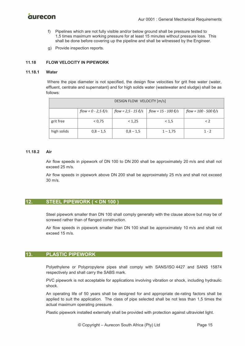
11.18 FLOW VELOCITY IN PIPEWORK
11.18.1 Water
Where the pipe diameter is not specified, the design flow velocities for grit free water (water,
effluent, centrate and supernatant) and for high solids water (wastewater and sludge) shall be as
follows:
DESIGN FLOW VELOCITY [m/s]
flow = 0 - 2,5 ℓ/s flow = 2,5 - 15 ℓ/s flow = 15 - 100 ℓ/s flow = 100 - 500 ℓ/s
grit free < 0,75 < 1,25 < 1,5 < 2
high solids 0,8 – 1,5 0,8 – 1,5 1 – 1,75 1 - 2
11.18.2 Air
Air flow speeds in pipework of DN 100 to DN 200 shall be approximately 20 m/s and shall not
exceed 25 m/s.
Air flow speeds in pipework above DN 200 shall be approximately 25 m/s and shall not exceed
30 m/s.
STEEL PIPEWORK ( < DN 100 ) 12.
Steel pipework smaller than DN 100 shall comply generally with the clause above but may be of
screwed rather than of flanged construction.
Air flow speeds in pipework smaller than DN 100 shall be approximately 10 m/s and shall not
exceed 15 m/s.
PLASTIC PIPEWORK 13.
Polyethylene or Polypropylene pipes shall comply with SANS/ISO 4427 and SANS 15874
respectively and shall carry the SABS mark.
PVC pipework is not acceptable for applications involving vibration or shock, including hydraulic
shock.
An operating life of 50 years shall be designed for and appropriate de-rating factors shall be
applied to suit the application. The class of pipe selected shall be not less than 1,5 times the
actual maximum operating pressure.
Plastic pipework installed externally shall be provided with protection against ultraviolet light.
Aur 0001 : General Mechanical Requirements
© Copyright – Aurecon South Africa (Pty) Ltd Page 16
Tappings, for example for gauges, shall be provided with welded, external doubler plates. The
plates shall have a thickness at least equal to the wall thickness of the pipe.
CAST IRON PIPEWORK 14.
Cast iron pipes and fittings shall comply with BS 2035 (Class D) and shall be pressure tested in
accordance with Clause 12 of that Standard. The requirements of the Standard's Clause 6
regarding freedom from defects and casting appearance and Clauses 8, 9 and 10 regarding
casting accuracy will be strictly applied.
Cast iron pipework shall comply with the requirements of the clause “Castings".
ELECTRIC MOTORS SMALLER THAN 30 KW 15.
15.1 GENERAL
Cage induction motors below 30 kW shall be rated for operation on a 3-phase, 4-wire,
400/230 Volt, 50 Hz, AC supply.
Motors shall be standard squirrel cage motors with IC 0141 cooling, shall be suitable for a damp
environment and shall comply with SANS 1804.
Bearings shall be of the oil or grease lubricated roller and/or ball type. Re-greasable bearings
shall be provided with grease nipples (with extension tubes where access is restricted) and
sealed to suit external use but with relief from over-greasing. L-10 design life shall not be less
than 100 000 hours.
Terminal boxes shall be top mounted wherever possible and arranged for cable entry from either
side. The two ends of each stator winding shall be "brought out" to the terminal box.
A stainless steel rating plate shall be secured to the frame. This shall include the lubrication
details.
Motors above 30 kg shall be provided with lifting eyes or lugs.
Motors may have nominal speeds above 1 500 rpm.
Ingress protection shall be to at least IP 55.
15.2 PERFORMANCE REQUIREMENTS
Motors shall provide rated power output at an ambient temperature of up to 40 ºC and at an
altitude of at least 1 500 masl.
The rated power of the motor shall be selected to be not less than 20 % in excess of the
designed power requirement of the driven equipment. The Engineer might waive this
requirement if the motor forms part of a factory packaged unit or another technical reason.
15.3 OPERATION AND CONTROL
Protection against both starting overload and running overload shall be designed and provided
so that it is specific to the application.
Aur 0001 : General Mechanical Requirements
© Copyright – Aurecon South Africa (Pty) Ltd Page 17
15.4 HAZARDOUS LOCATIONS
When required to suit a hazardous location in terms of SANS 10108 or in terms of this
Specification, suitable motors complying with SANS 60034-5 or SANS 61241, as appropriate, shall
be supplied. The relevant SANS certificates, clearly indicating the location classification in which
the machine may be operated, shall be submitted to the Engineer before delivery of the motors.
Each motor shall be clearly and permanently marked with the applicable certificate number.
15.5 VFD DRIVEN MOTORS
Unless of the submersible or immersible type, VFD driven motors shall be cooled by a separate,
50 Hz motor driven "piggy-back" fan (this requirement will be waived if the Contractor can
provide documentation to confirm that the drive and motor design can operate in the application,
with conventional shaft-mounted fan, without overheating).
Motors shall incorporate protection against damage to the bearings from induced currents.
15.6 CORROSION PROTECTION
Motors shall be provided with the motor manufacturer’s highest grade of corrosion protection
coating available.
Fan cowls shall be of cast iron, stainless steel or plastic; i.e. shall not be of carbon steel.
15.7 SAFETY
Rotating parts shall be guarded as required by legislation.
ELECTRIC MOTORS OF 30 KW AND LARGER 16.
16.1 GENERAL REQUIREMENTS
Cage and slipring induction motors of 30 kW and above shall comply with this clause.
400 Volt motors shall be tefc with an ingress protection of at least IP 55 and with rolling element
bearings.
Motors with a rating above 1 000 kW shall be of CACA configuration with oil lubricated sleeve
bearings.
Motors shall be suitable for both "continuous running duty", Duty Class S1, and "intermittent
periodic duty", Duty Class S3. Windings shall be insulated with Class F material (100 ºC rise
capability) with Class B temperature rise (80 ºC). The motors shall be suitable for 6 starts per hour,
two of which shall be consecutive.
The type of motor (and starter if applicable) to be supplied is determined by the requirements of the
application specified and by any starting limitations specified. In the absence of such specifications,
a standard squirrel cage motor shall be provided.
Wound rotor motors shall have a separate enclosure for the slip-ring assembly to ensure that dust
does not enter the motor. The rings shall preferably be of stainless steel. The enclosure shall have
the same ingress protection as the main motor enclosure but shall have covers for direct access to
the assembly.
If a special motor is required to obtain special starting characteristics and/or variable speed, a full
technical specification of the motor must be supplied and such specification shall be for equipment
Aur 0001 : General Mechanical Requirements
© Copyright – Aurecon South Africa (Pty) Ltd Page 18
to a standard at least equal to this specification and shall incorporate all aspects of electrical
protection.
Motors shall be structurally suitable for DOL starting. This includes motors which are VFD driven.
Motors shall be provided with lifting eyes or lugs.
An earth terminal shall be provided on the frame. Access shall be provided to the winding neutral
point.
Protection against both starting and running overload shall be designed and provided so that it is
specific to the application.
All monitored motor parameters; e.g. bearing temperature, winding temperature, current, etc.; shall
be indicated and shall be provided on the SCADA or HMI mimics, if applicable.
Motors shall be of the reduced noise level type unless otherwise specified.
Motors shall be adequately protected against corrosive environments and shall be provided with
the motor manufacturer’s highest grade of coating available.
Motors of size 75 kW and above shall be fitted with "pocket" heaters. The heater shall be
mounted at the bottom of the motor frame and shall be replaceable without dismantling the
motor. These shall be arranged to switch on when the motor stops operating and switch off
when it starts operating.
A stainless steel rating plate shall be secured to the frame. This shall include the lubrication
details.
Measured vibration severity shall meet the requirements of Zone A or Zone B of ISO 10816.
When motors are transported, care shall be taken to prevent damage to bearing elements. The
shaft shall either be secured against relative movement and/or the motor base shall be mounted
on suitable anti-vibration mounts during transport.
16.2 PERFORMANCE REQUIREMENTS
Motors shall be provided and shall perform in accordance with the requirements of the specified
mechanical equipment.
Motors shall provide rated power output at an ambient temperature of up to 40 ºC and at an
altitude of at least 1 500 masl.
The rated power of the motor shall be selected to be not less than 15 % in excess of the designed
power requirement of the driven equipment (the Engineer might override this requirement if the
motor forms part of a factory packaged unit or another technical reason).
Motors shall reach full operating speed within 5 seconds unless driven by electronic soft start or
variable speed drive.
16.3 400 VOLT MOTORS
Motors shall be rated for operation on a 3-phase, 4-wire, 400/230 volt, 50 Hz, AC supply and shall
comply with SANS 1804.
Except as otherwise specified or as required by the design of the installation, motors shall be
standard squirrel cage or slip-ring motors with IP55 enclosure and IC 0141 cooling and shall be
suitable for a damp environment.
Motor frames shall be of the totally enclosed fan cooled type with cast iron stator frames and cast
iron end covers. The frame and end covers shall be properly machined and each cover shall locate
on a spigotted register to ensure concentricity and parallelism.
Aur 0001 : General Mechanical Requirements
© Copyright – Aurecon South Africa (Pty) Ltd Page 19
Terminal boxes shall be top mounted wherever possible and arranged for cable entry from either
side.
16.4 3,3 KV, 6,6 KV, 11 KV AND 15 KV MOTORS
Motors shall be rated for operation on a 3-phase, 4-wire, 50 Hz, AC supply.
16.5 TEFC MOTORS
The fan cowl shall be of cast iron, plastic or stainless steel; i.e. carbon steel cowls are not
acceptable.
An internal cooling circuit fan shall be provided for frame sizes 355 and larger.
If it is required that the motor shall produce low sound output, the fan cowl shall be provided with
internal damping.
16.6 CACA MOTORS
CACA motors shall have IP 55 ingress protection rating unless otherwise specified.
The heat exchanger shall be provided with lifting eyes or lugs.
Fans shall have cooling air inlet silencers and shall have outlet silencers.
Rotors shall be dynamically balanced.
The drive end bearing shall be earthed to prevent shaft currents.
Ports shall be provided for air gap measurement at the drive end and at the non-drive end.
Vertical jacking shall be provided at each holding down point.
At least one internal cooling circuit fan shall be provided for frame sizes 355 and larger.
16.7 HAZARDOUS LOCATIONS
When required to suit a hazardous location in terms of SANS 10108 or in terms of this
Specification, suitable motors complying with SANS 60034-5 or SANS 61241, as appropriate, shall
be supplied.
The relevant SANS certificates, clearly indicating the location classification in which the machine
may be operated, shall be submitted to the Engineer before delivery of the motors.
Each motor shall be clearly and permanently marked with the applicable certificate number.
16.8 ELECTRONIC VARIABLE SPEED DRIVE
Motors which will be driven by electronic variable speed drives shall be designed for the
application and their design shall be submitted to the Engineer for approval. The design shall
consider and deal with harmonic currents and with protection against bearing damage.
Unless of the submersible or immersible type, VFD driven motors shall be cooled by a separate,
50 Hz motor driven "piggy-back" fan.
Motors shall incorporate an insulated bearing and shall incorporate an earthing brush at the
drive end.
16.9 BEARINGS
Bearings shall comply with the clause “Bearings”.
Aur 0001 : General Mechanical Requirements
© Copyright – Aurecon South Africa (Pty) Ltd Page 20
Each bearing shall be mounted in a cartridge housing which is securely attached to the end covers.
Grease lubricated rolling element bearings shall be re-greasable during motor operation. They
shall be provided with stainless steel grease nipples (with stainless steel extension tubes where
access is restricted) and shall be suited for external applications. A port for relief against
over-greasing shall be provided.
Bearings on the non-drive end shall be insulated. Drive end bearings shall preferably be
earthed.
Bearings for motors of 300 kW and above shall be provided with temperature measurement,
indication and alarm.
Bearings for motors in belt drive applications shall be of the rolling element type; i.e. shall not be
plain bearings.
16.10 MOTOR SPEED
(This sub clause does not apply to high speed motors with special bearings)
For motors with ratings between 30 kW and 132 kW (both inclusive), preference shall be given
to nominal speeds of 1 500 rpm or lower.
Motors with ratings above 132 kW shall have a nominal speed of 1 500 rpm or below.
16.11 INSTRUMENTATION
Motors of 30 kW and up to (but not including) 150 kW shall be provided with thermistors embedded
in the windings of each phase. The thermistor tails shall be "brought out" to separate terminals
mounted near the motor winding terminal block.
Motors rated at 150 kW and above, both fixed and variable speed, shall be provided with PT 100
type RTDs. Two RTDs shall be provided per phase winding. All six shall be incorporated into
the control system; three to provide monitoring and three to provide high temperature trip
functions.
16.12 SAFETY
Rotating parts shall be guarded as required by legislation.
PLINTHS & BASEFRAMES 17.
17.1 GENERAL
The Contractor shall provide the baseframe, anchor fasteners and chemical anchor, or
equivalent, for securing the fasteners.
Equipment and drivers shall be mounted on either a baseframe or on soleplates and shall not be
mounted directly onto the plinth.
Driven equipment up to 1 000 kW and their drivers shall be mounted on common cast iron or
fabricated steel baseframes of rigid construction. This requirement applies to both direct
coupled and belt driven machines.
Separate baseframes or sole plates may be used for equipment above 1 000 kW. Base frames
(or sole plates) for units of this size shall be grouted within concrete plinths.

Aur 0001 : General Mechanical Requirements
© Copyright – Aurecon South Africa (Pty) Ltd Page 21
The Contractor shall construct the concrete plinths unless this requirement is overridden by the
project specification.
17.2 PLINTHS
Plinths for machinery above 75 kW shall be isolated from the surrounding floor and other
machinery plinths. This requirement does not apply to machinery which is mounted on
proprietary anti-vibration mounts for acoustic and vibration isolation from the building.
The Contractor shall design the reinforced concrete plinth and shall submit the design
calculations to the Engineer for acceptance.
The calculations shall confirm that the equipment’s enforcing vibration will cause no damaging
resonant condition. If the plinth rests directly on soil, the calculations shall also demonstrate that
the design is suitable for the ground conditions without undue settlement.
The design shall ensure that all forces, including the motor breakdown torque (or equivalent
force if the driver is not a motor) will be accommodated.
Plinths shall, nevertheless, comply with the following minimum requirements:
· Plinth mass shall be greater than five times the total mass of the equipment.
· Width of plinth shall be greater than the height between the shaft centreline and the bottom of the plinth.
· Height of plinth shall be greater than one fifth of the width.
· Height of plinth shall be greater than one tenth of the length.
17.3 BASEFRAMES
17.3.1 General
The Contractor shall anchor the baseframe to the plinth and shall provide the baseframe
grouting, anchor fasteners and chemical anchor for securing the fasteners.
17.3.2 Design
The Contractor shall submit the baseframe fabrication drawing to the Engineer for acceptance.
Baseframes shall have dimensions which comply with the following minimum requirements:
· The longitudinal member shall have a height of at least 0,09 times the length of the baseframe.
· The longitudinal member shall have a height of at least 0,18 times the width of the baseframe.
Baseframes fabricated from cold formed plate shall also comply with the following:
· The plate thickness shall have a thickness greater than 0.004 times the length of the baseframe (but with a minimum of 4,5 mm).
Baseframes shall prevent pooling of water and shall be grout filled or shall be provided with
drain holes in all side members.
The baseframe shall incorporate machined mounting pads for each equipment foot. Machining
shall be done after fabrication, stress relieving and hot-dip galvanizing are complete. The
thickness of the mounting pads shall be not less than 1,25 times the diameter of the holding
down bolts. The pads shall be drilled for inserting through-bolts (i.e. not machine screws in
threaded holes) and adequate provision shall made for reaching the nut. In the period between
machining and installation of the equipment, the machined surface shall be protected against
corrosion by a removable coating. After installation, a non-hardening compound, Tectyl or
Aur 0001 : General Mechanical Requirements
© Copyright – Aurecon South Africa (Pty) Ltd Page 22
equivalent, shall be applied to exposed machined surfaces and to the crevices formed at the
foot of the equipment.
Holes for mounting of conduits, etc. are acceptable on condition that these are provided prior to
galvanising and are positioned on the neutral axis. Drilling after galvanising will be a cause for
rejection
17.3.3 Jacking Points
In the case of belt-driven units, at least two diagonally opposed jacking screws shall be provided
for belt tensioning.
Direct coupled motors above 10 kW shall be provided with jacking screws for horizontal
alignment and direct coupled motors above 150 kW shall also be provided with jacking screws
for vertical alignment.
Jacking screws shall be of hot-dip galvanised steel or of EN Grade 1.4401 (316), or better.
The jacking point shall consist of a suitable hot rolled steel section welded to the baseframe and
with a captured machine nut to accept the jacking screw. Drilled and tapped flat plate is not
acceptable for jacking points.
17.3.4 Fabrication
Fabrication of baseframes shall comply with the clause “Fabrication of Carbon Steel and
Stainless Steel” and welding shall comply with the clause “Welding”.
If the Engineer agrees to an organic coating system rather than hot-dip galvanising, practical
requirements for providing accessibility for surface preparation and coating shall be taken into
consideration. Hidden surfaces are not acceptable. Inaccessible pockets and hollow spaces
which cannot be accessed by blast and spray equipment shall be avoided or shall be welded
closed.
17.3.5 Materials
Baseframes shall be fabricated from steels complying with SANS 50025 for grade S 355 JR or
for grade S 355 JO.
Manufacturer’s standard stainless steel baseframes will be acceptable.
17.3.6 Corrosion Protection
Steel baseframes shall be hot-dip galvanized in accordance with Aur 0003.
Designs shall provide proper access for safe and complete entry of the zinc.
17.3.7 Anchor Fasteners
Anchor fasteners shall be of EN Grade 1.4401 (316), or better. Fasteners shall comply with the
clause “Fasteners”.
Anchor fasteners shall be provided with both a lock washer and a flat washer.
A minimum of six anchors shall be provided for pumps with an inlet of DN 150 and smaller. Eight or
more anchors shall be provided for pumps with an inlet larger than DN 150. Anchor fastener size
shall be in accordance with the table below.
Pump Inlet Fastener Size (Minimum)
Aur 0001 : General Mechanical Requirements
© Copyright – Aurecon South Africa (Pty) Ltd Page 23
DN 50 M10
DN 100 M12
DN 200 M12
DN 300 M16
DN 400 M20
DN 500 M24
DN 600 and larger M30
17.3.8 Installation
Not more than three shims may be used at any point and these shall be of a corrosion resistant
material.
Concrete surfaces under baseframes shall be scabbled before the baseframe is placed and
shall be blown clean using compressed air immediately before grouting.
Baseframes shall be designed and grouted to eliminate collection points for water or dirt.
Unless otherwise approved by the Engineer, baseframes on concrete plinths shall be fully
grouted in. Grouting holes must be provided on baseframes having a continuous top plate.
Tapped holes and fixing setscrew protrusions shall be suitably protected. The material used for
grouting shall be a non-shrink, cementitious grout (ABE Duragrout 1000, or equivalent).
ABE Epidermix 324, or equivalent, is acceptable if an epoxy grout is required. The first unit
grouted shall be overseen by the grout supplier's technical representative.
Preliminary alignment of equipment mounted on baseframes shall be done at the factory to
ensure that the baseframe has been correctly manufactured but final alignment shall always be
done on Site after installation and grouting has been completed.
Alignment shall be accurate and to the approval of the Engineer and a final alignment check
witnessed by the Engineer must be carried out by the Contractor prior to start up.
17.3.9 Inspections
The Contractor shall arrange for the Engineer to inspect the fabrication of the baseframe (before
hot-dip galvanising where applicable).
MACHINE GUARDS 18.
Guards shall comply in all respects with the Occupational Health and Safety Act of 1993 as
amended.
Guards are required to cover all moving or revolving components of machinery and shall prevent
a person from touching any moving protrusion. Guards which do not adequately cover moving
Aur 0001 : General Mechanical Requirements
© Copyright – Aurecon South Africa (Pty) Ltd Page 24
protrusions such as keys, lock nuts, lock washers, setscrews, etc., or irregularities such as
keyways, will under no circumstances be accepted.
Guards shall be neatly and rigidly constructed and fixed and shall not vibrate or cause noise
during operation.
Where expanded metal or similar mesh is used, the mesh opening shall not permit a circular
object 10 mm or larger to penetrate. Mesh shall not be used for chain guards but on belt drives
the side of the guard most conveniently sited for inspection shall be constructed of expanded
metal or similar. Mesh should similarly be used in other situations where inspection or
ventilation is required.
Allowance must be made for adjustment where adjustment will be required such as on belt
guards.
It shall be possible to remove guards easily for maintenance purposes.
Guards shall preferably be fabricated of EN Grade 1.4401 (316) stainless steel (uncoated) but
may also be hot-dip galvanized, hot metal zinc-sprayed or hot metal aluminium-sprayed carbon
steel, coated to Specification in all these cases. Fasteners shall be M10 or larger and shall be
of EN Grade 1.4401 (316) stainless steel.
SHAFT COUPLINGS 19.
Shaft couplings shall be selected to reduce transmission of misalignment forces and of torsional
oscillations between the driving and the driven machine. Couplings shall, wherever practical, be
of the rubber tyre or rubber compression type, keyed to the shafts.
Elastomeric elements shall be urethane based. Flexible metallic elements shall be of stainless
steel. Couplings shall not require lubrication.
Spacer couplings shall be used where required for disassembly of the equipment. It shall be
possible to dismantle the coupling without having to move either the driver or the driven
equipment.
Coupling guards shall comply with the requirements of the OHS Act and shall be to the approval
of the Engineer.
After installation, the alignment of all couplings shall be checked by the Contractor in the
presence of the Engineer or a person delegated by him. Alignment shall be accurate and to the
approval of the Engineer.
BELT DRIVES 20.
Belt drives shall be designed to suit the power rating of the motor using service factors
appropriate to the driving and driven machinery. Drives shall be designed, manufactured and
installed in accordance with BS 3790 and ISO 4184 or equivalent, utilizing taperlock pulleys with
taperlocks keyed to the shaft.
Where alternative pulley diameters can be selected, preference must be given to the larger
pulley diameters to minimize the belt loading on bearings.
Aur 0001 : General Mechanical Requirements
© Copyright – Aurecon South Africa (Pty) Ltd Page 25
The bearing arrangements of driving and driven machinery shall be designed to cope with the
loads imposed by belt drives. Rolling element bearings shall be designed for an L-10 life
exceeding 100 000 hours.
Belt drives shall incorporate lay shafts where necessary. Lay shafts shall be supported by
bearings mounted in bearing housings which are adequately sealed and fitted with grease
nipples. Bearing units incorporating open, shielded bearings are not acceptable.
Belt driven machinery shall be equipped with rolling element bearings; i.e. shall not be equipped
with plain bearings.
MOTOR DRIVEN GEARBOXES 21.
21.1 GENERAL
Gearboxes shall be supplied with environmental protection to IP 55 or higher.
Gearboxes shall have an efficiency of not less than 96 % on two stage reduction and 95 % on
three stage reduction.
21.2 SERVICE FACTOR
21.2.1 Motor Driven Gearboxes
The service factor to be used for the design of gearboxes in uniform load duty shall be at
least 1,25 for electric motor driven applications. A minimum service factor of 1,5 shall be used
for moderate shock applications and a minimum service factor of 2 shall be used for heavy
shock applications.
21.2.2 Engine driven gearboxes
The service factor to be used for engine driven gearboxes shall not be less than 2.
21.3 DESIGN REQUIREMENTS
Gears shall be case hardened, profile ground and lapped, helical and spiral bevel gears.
The gearbox housing shall be of rigid cast construction preferably split in the horizontal plane.
Unless close coupled, each gearbox shall be mounted on machined sole plates fitted with
jacking screws to assist with alignment.
Rolling element bearings shall be designed for an L-10 life in excess of 100 000 hours.
A breather designed to prevent moisture from entering shall be fitted.
21.4 LUBRICATION
Oil-bath gearboxes shall have suitable oil level indicators or dipsticks which indicate the
allowable levels. Inaccessible oil drain points shall be provided with extensions so that the oil
can be easily drained. The drain line shall be of EN Grade 1.4401 (316) stainless steel and
shall be fitted with a ball valve and square head plug.
Grease lubrication points shall be easily accessible. Grease nipples shall be of stainless steel.
Aur 0001 : General Mechanical Requirements
© Copyright – Aurecon South Africa (Pty) Ltd Page 26
21.5 OIL CHANGE
The Contractor shall drain and replace oil in all gearboxes during the Defects Notification Period.
MANUAL GEARBOXES 22.
An over-torque limiting device shall be incorporated.
Grease lubrication points shall be easily accessible. Grease nipples shall be of stainless steel.
A breather designed to prevent moisture from entering shall be fitted.
BEARINGS 23.
23.1 BEARING CHOICE
Bearing design shall suit the requirements of the equipment and the installation.
Greased lubricated bearings are acceptable for units with power ratings up to 100 kW but oil
lubricated bearings are preferred for larger machines.
Units with power ratings above 1 000 kW shall be provided with plain bearings (oil film type).
Plain bearings are also preferred for units with high speed shafts and for high temperature
applications.
23.2 OPERATIONAL REQUIREMENTS
Bearing designs shall ensure safe shut down without damage following electrical supply failure.
Bearing designs for variable speed drive applications shall be suitable for the full expected
speed range.
23.3 ROLLING ELEMENT BEARINGS
For shaft sizes above 50 mm, the bearing shall be selected for an L-10 bearing life of at least
100 000 hours. This may be reduced if the equipment is expected to operate for less than
3 000 hours in a normal year.
Grease lubricated rolling element bearings shall be provided with relief against over greasing.
Oil lubricated rolling element bearings shall be provided with an oil ring.
23.4 PLAIN BEARINGS
Plain bearings (“slide bearings”, “oil-film bearings” or “sleeve bearings”) which are oil lubricated
shall have lubrication by oil ring, by rotating dish or by pumped feed or by a combination of
these. Lubrication shall be active during normal run down and during power failure and shall
cause no damage to the bearing.
Small diameter bushes shall preferably be self-lubricated sintered metal or of engineering
polymer with suitable lubrication.
Aur 0001 : General Mechanical Requirements
© Copyright – Aurecon South Africa (Pty) Ltd Page 27
23.5 THERMAL ALARMS
Thermal alarms on bearing systems shall be set in accordance with the equipment
manufacturer’s instructions.
Alarm settings done on Site shall be set after at least 24 hours of operation have occurred.
If high temperature protection is specified for a bearing, the Contractor shall note the equilibrium
temperature reached after 30 minutes of normal operation and shall also note the ambient
temperature. The high level trip temperature shall then be calculated as follows:
Ttrip = Tequilibrium + (40ºC -Tambient) + 10ºC.
(This assumes that the bearing is operating correctly.)
23.6 BELT DRIVEN EQUIPMENT
Belt driven machinery and belt drive motors shall be equipped with rolling element bearings;
i.e. shall not be equipped with plain bearings.
LUBRICATION 24.
24.1 TYPE
Grease lubrication is generally acceptable where design parameters are not severe. Oil
lubrication shall be provided where the design parameters are more severe.
Lubrication systems shall be designed to exclude dirt and moisture. Air vents on the oil
reservoir shall incorporate filters. Drain facilities shall always be provided.
24.2 GREASE LUBRICATION
Where a grease point is not easily accessible, a grease line shall be piped to an easily
accessible position for manual greasing. Each grease point shall be provided with its own
grease point and pipework.
A distributor shall be provided where motorised lubrication is provided to more than one
destination. The distributor shall be a positive displacement device which ensures equal,
successive lubrication to all destinations. Only one distributor shall be used for each lubrication
pump; i.e. distributors shall not be cascaded.
Pipework for grease distribution shall be of stainless steel.
24.3 OIL LUBRICATION
Where oil lubrication is provided, the Contractor is responsible for the initial oil fill and the first oil
change, including flushing, draining and filling, after an initial run in period not exceeding
3 months
Oil level indicators shall be provided for visual checking. Drain valves, including
EN Grade 1.4401 (316) fittings where necessary to permit convenient draining, and plugged at
the end, shall be provided for oil reservoirs exceeding 1,5 litre capacity. Drains shall be from the
lowest point and syphon type drains are unacceptable.
Aur 0001 : General Mechanical Requirements
© Copyright – Aurecon South Africa (Pty) Ltd Page 28
24.4 SUBMERGED BEARING HOUSINGS
Submerged bearing housings;; shall be grease lubricated by motorised lubrication. The seals
shall be arranged to avoid overgreasing of the bearing. These requirements apply to the bottom
bearings of equipment such as Archimedes screw pumps but do not apply to equipment such as
submersible pumps in which the bearing housing is contained within the pumpset housing
GAUGES 25.
25.1 CONSTRUCTION
Gauges shall be of industrial construction. The case and bezel shall be of stainless steel unless
this material is unsuitable for the application.
Pressure, vacuum or compound gauges shall comply with SANS 1062 and shall bear the
Standards mark. Gauges shall be of Accuracy class 1.6 and Durability grade A unless
otherwise specified.
The gauge reading shall indicate gauge pressure unless absolute pressure measurement has
been called for.
Gauges shall have a scale diameter of not less than 100 mm.
Calibration shall be in mWC (metres Water Column) unless otherwise specified. The units of
measurement shall be clearly marked on the dial.
The scale shall be chosen so that the expected pressure is not less than half full scale reading
but the full scale reading for a gauge on the discharge leg of a centrifugal pump shall be higher
than the pump shut off head.
Wherever applicable, gauges shall be clearly strip marked in green to indicate the normal
operating range and in red to indicate the non-permissible range of values.
Gauges shall be suitable for continuous operation and shall be glycerine filled on all pump
applications and where fluctuations in pressure may cause damage.
Scale markings shall be radial, plain, straight, black lines on a white background and shall be
spaced so that one scale division represents approximately 1,5 % of the maximum scale value
in values of 1, 2 or 5 multiplied by any power of 10 to suit the maximum operating rating. On
circular gauges the scale shall be concentric and the maximum and minimum scale values shall
be near the bottom of the gauge, with the scale symmetrically disposed about the vertical centre
line of the gauge. The tip of the pointer shall be of the knife edge type extending across the
scale divisions and shall be as close as practical to the dial.
25.2 INSTALLATION
Gauges shall not be mounted directly on equipment subject to vibration.
Gauges for pipework larger than DN 250 shall be remotely mounted and isolating valves shall
be provided at each end of the connecting pipework.
Gauges shall be mounted vertically and in such a position that they can be easily read from floor
level.
Nozzles/sockets for gauges shall be provided in accordance with the clause “Steel Pipework;
DN 100 and Larger”.
Aur 0001 : General Mechanical Requirements
© Copyright – Aurecon South Africa (Pty) Ltd Page 29
Pressure gauges shall be fitted with an isolating and an air bleed valve. Valves shall be
stainless steel ball valves with stainless steel operating levers.
Gauges for sludges and other liquids which contain solids shall have their nozzles on the side of
the parent pipe. The configuration shall allow easy cleaning of the passageways.
Gauges used on wastewater, sludge, chemical, solids conveying or other applications where
blockage or corrosion of the gauge is possible shall be fitted with a diaphragm type chemical
seal, both being liquid filled. The portion of the seal in contact with the process liquid shall be of
a suitable non-corroding material.
When used on steam lines a siphon shall be fitted between the steam line and the gauge which
shall be filled with water before it is put into service.
ELECTRONIC INSTRUMENTATION 26.
Environmental protection of electronic instrumentation shall be as follows:
a) Instrumentation and associated displays and transmitters which are either located inside
or located outside and above ground level shall have IP 55, or higher, rating.
b) Instrumentation and associated displays and transmitters which are located in
underground chambers shall have IP 68 environmental protection. The instrument shall
be mounted in an enclosure which shall provide physical protection and shall be
self-draining.
c) Instruments and associated displays and transmitters which are located outside
buildings shall be mounted in enclosures. Enclosures shall be of polycarbonate
construction with transparent front, Fibox EK or equivalent. The complete enclosure
installation shall have an IP 55 rating or higher. The enclosure size shall be chosen to
provide a clearance of at least 100 mm all around the instrument.
Instruments and their cabling shall be protected so that electromagnetic interference does not
affect their operation and signal transmission.
Instruments shall have permanently affixed nameplates.
Calibration certificates shall be included in the Manual.
GUARD RAILS 27.
27.1 GENERAL
Legislated requirements call for guard railing to be provided in positions where the vertical
change in level is 1 000 mm or greater.
Guard railing shall comply with SANS 10104 and shall be designed for access for maintenance
purposes.
27.2 OPERATIONAL REQUIREMENTS
Guard railing shall be designed to resist, without any damage and without excessive deflection,
the loadings in Category E in Table 7 in Clause 9.4 of SANS 10160 2:2011, Edition 1.1, namely:
a) a force of 1 000 Newtons in any direction (concentrated over a length of 100 mm).
b) a distributed horizontal force of 1 000 Newtons per metre applied along the top rail.
Aur 0001 : General Mechanical Requirements
© Copyright – Aurecon South Africa (Pty) Ltd Page 30
27.3 DESIGN REQUIREMENTS
Guard railing shall be designed to resist the loadings set out in SANS 10160.
Hand and knee rails shall have an outside diameter of not less than 33 mm and a wall thickness
of not less than 2,5 mm and a maximum span of 1 500 mm (greater spans will be acceptable if
heavier tube dimensions are used).
Tubular stanchions shall have a wall thickness of at least 3,0 mm.
On platforms, walkways, landings or around dangerous areas the vertical height, measured from
the top of the hand rail to the floor or surface, shall be at least 1 000 mm.
On stairways and fixed ladders the rails shall be parallel to the strings, and the vertical height,
measured from the top of the hand rail to the nosing of the tread, shall be at least 900 mm.
No opening between rails shall allow the passage of a ball of diameter 600 mm.
Stanchions and rails shall be smoothly finished and free from sharp corners, edges and
projections which may injure persons or damage clothing. Stanchion bases shall have the
corners rounded or sheared off.
Welded guard rail installations are preferred. Installations which incorporate bolted sections
shall be secure and tight under loading. “Pop” rivetted installations will not be acceptable.
Joints shall be smoothly finished, without shoulders.
Railings shall be ended off with positively fixed closure bends. At corners, short radius bends
with stanchions on both ends shall be employed or, alternatively, stanchions specifically
designed for such a position shall be employed. No sharp ends will be permitted.
Stanchions shall generally be base-mounted to suit the arrangement requirements and shall be
of solid or welded construction.
Stanchions which are hollow shall be self-draining.
Stanchion feet which are attached to metallic surfaces shall have minimum dimensions of
150 mm X 60 mm X 8 mm. Two fasteners, of minimum size M16, shall be used to secure each
foot. Neatly fitting packing, Denso tape or equivalent, shall be fitted under stanchion feet to
prevent the formation of crevices.
Stanchion feet which are attached to non-metallic surfaces shall have minimum dimensions of
150 mm X 150 mm X 10 mm. In instances where the horizontal surface to which the foot is to
be fastened is less than 150 mm wide, the foot shall be designed to be seated on at least two
surfaces. Four fasteners, of minimum size M16, shall be used to anchor the foot. Non-shrink,
cementitious grout shall be applied under the foot just prior to final tightening of nuts.
Where kickplates are required by legislation, these shall extend to 150 mm above the walkway
level.
27.4 ADDITIONAL DESIGN REQUIREMENTS FOR GUARD RAILING IN PUBLIC PLACES
The requirements for guard railing at equipment installations shall also apply for guard railing for
public places. The following specific requirements shall also be complied with:
a) The structural design shall be done in accordance with the requirements of
SANS 10104.
b) No opening in guard railing installed in public places shall allow the passage of a ball of
100 mm diameter.
Aur 0001 : General Mechanical Requirements
© Copyright – Aurecon South Africa (Pty) Ltd Page 31
27.5 CARBON STEEL GUARD RAILS
Fabrication and welding shall comply with the clauses “Fabrication of Carbon Steel and
Stainless Steel” and “Welding”.
The guard rails shall be hot-dip galvanised. Designs shall provide proper access for safe and
complete entry of the zinc into open spaces so that subsequent drilling at the galvaniser’s yard
is avoided.
If the guard rails are welded or cut after hot-dip galvanising, they shall be returned to the
galvaniser for re-galvanising.
27.6 STAINLESS STEEL AND 3CR12 GUARD RAILS
Fabrication and welding shall comply with the clauses “Fabrication of Carbon Steel and
Stainless Steel” and “Welding”.
27.7 FASTENERS
All anchor fasteners, including nuts and washers shall be of EN Grade 1.4401 (316) stainless
steel.
Fastener diameter shall not be less than M12.
GRID FLOORING 28.
The depth of bearer bars in metal grid flooring shall not be less than 30 mm with a bearer bar
pitch of not greater than 40 mm.
The bearer bars shall be across the shorter span.
Panels shall be set level and fixed to angle frames to prevent rocking.
Cut-outs in grid flooring for pipes, valve spindles, etc. are to be fully banded. The edges of
removable grid access covers must also be fully banded. Corrosion protection shall only be
done after welding of banding has been completed.
Unless another material such as stainless steel is specified, grid flooring and frames shall be of
carbon steel, hot-dip galvanized after fabrication. If hot-dip galvanising is not suitable, a glass
flake resin, such as Power Blast’s Vitaglass or equivalent which is applied by dipping the flooring
in catalysed resin, is acceptable. Painted coatings are not acceptable as corrosion protection.
Where grid flooring rests on painted surfaces, strips of rubber insertion material shall be secured
under the grid to protect the paint.
The fixing clip set (saddle clamp and locking plate) shall be of hot-dip galvanised steel or
stainless steel. Fasteners shall be of EN Grade 1.4401 (316), or better.
GRP grid flooring is not acceptable.
Aur 0001 : General Mechanical Requirements
© Copyright – Aurecon South Africa (Pty) Ltd Page 32
FASTENERS 29.
29.1 STANDARDS
Bolts and nuts shall be hexagon head type complying with SANS 1700 with threads of the
coarse pitch series.
29.2 MATERIALS
M12 fasteners and smaller shall be of EN Grade 1.4401 (316) or better.
Fasteners in corrosive areas shall be of EN Grade 1.4401 (316) or better. Corrosive areas shall
be taken to include any moist or wet area such as in and above settling tanks, in or in the vicinity
of open channels, where a continuous spray can be expected and all areas in the vicinity of a
wastewater treatment works or wastewater sump.
Fasteners larger than M12 which are in non-corrosive areas shall, except when specified
otherwise, be hot-dip galvanized.
Plated fasteners are not acceptable.
29.3 HIGH TENSILE BOLTS
Where high tensile bolts are required by the design, they shall be hot-dip galvanized and
painted. The bolt holes and crevices shall be filled and sealed prior to painting.
29.4 ANCHOR FASTENERS
Anchor fasteners shall be of EN Grade 1.4401 (316), or better.
Anchor fasteners for water retaining structures and for brickwork shall be of the chemical anchor
fastening type. Other anchors may be of the expanding type or chemical anchor type.
Where hook bolts are used, these shall be supplied and grouted by the Contractor into pockets
which will be provided in the concrete structure in accordance with the information to be
supplied by the Contractor. The grouting products shall be used strictly in accordance with the
manufacturer's instructions.
Where machinery is anchored by studs or bolts which extend through the supporting structure
and is therefore fastened down with the use of nuts from both sides, the studs or bolts, together
with associated washers and brackets, shall also be of EN Grade 1.4401 (316), or better.
Submerged anchors shall be secured with chemical anchor designed for submersion.
29.5 MATERIAL COMPATIBILITY
Fastener material shall always be of equal or better corrosion resistance than the items being
fastened, e.g. EN Grade 1.4401 (316) bolts must be used to fasten together EN Grade 1.4401
stainless steel flanges and fabrications.
29.6 WASHERS
Flat washers shall be provided under nuts and setscrew heads.
Flat washers shall be provided under bolt heads on painted surfaces.
Flat washers shall be provided under bolt heads where the bolt is positioned in a slot.
Aur 0001 : General Mechanical Requirements
© Copyright – Aurecon South Africa (Pty) Ltd Page 33
Spring washers shall be used on fasteners subject to vibration (other approved locking
arrangements will also be acceptable on proprietary equipment).
Anchor bolts for machinery shall each be provided with a flat washer and a spring washer (other
locking arrangements are not acceptable).
Washers shall be of the same material as the fasteners.
Flat washers exhibiting visual deformation shall be replaced by thicker washers.
29.7 ANTI-SEIZE COMPOUND
Before assembly, stainless steel threads shall be treated with a nickel-based,
anti-seize/corrosion protection compound such as Chesterton 725 : Nickel Anti-Seize
Compound, or equivalent. Copper based compounds are not acceptable.
A small amount of the compound shall be applied along the full length of the exposed thread
before fastening. Excessive compound visible on the thread after the nut has been applied shall
be cleaned off.
29.8 THREAD PROJECTION
Bolt threads shall project no less than 1 thread and no more than 8 threads from the head of the
nuts when fixed. Longer projections will only be allowed if the Contractor can show that bolts of
a more suitable length are not manufactured.
29.9 CORROSION PROTECTION
After installation, the exposed surfaces of fasteners not of stainless steel shall be coated as for
the items being fastened.
If the use of Allen head or similar fasteners has been approved by the Engineer, the recessed
heads shall be filled with a suitable non-hardening sealing compound.
MACHINE VIBRATION 30.
The mechanical vibration of machines measured at all important points such as bearings shall
be lower than that specified as "good" for that class of machine in BS 7854 (ISO 10816).
Reciprocating machines shall be designed and installed so that the machine vibrations are
isolated from the floor structure. Vibration isolation mountings which will eliminate not less than
90 % of the vibrations transmitted by the equipment shall be provided between the baseframe
and the concrete plinth. When mounted on the vibration isolators, distortion of the baseframe
shall be negligible in comparison with the permissible and acceptable misalignment of the
equipment mounted thereon.
Shafts shall be designed so that the critical speed is outside the operating speed range.
Aur 0001 : General Mechanical Requirements
© Copyright – Aurecon South Africa (Pty) Ltd Page 34
NOISE CONTROL 31.
31.1 GENERAL
Noise emitted by equipment shall be kept to a minimum and shall not exceed the noise levels
specified in these documents.
31.2 NOISE LEVELS
The sound power of any equipment shall not exceed 89 dB(A) (referred to 10-12
Watts) unless
specifically approved by the Engineer. This is approximately equivalent to a sound pressure
level of 81 dB(A) at a radius of one metre from the acoustical centre assuming uniform
hemispherical propagation in a free field on a hard floor. In certain instances, a lower noise
level may be called for.
Where the Contractor is unable to restrict the noise level of the machines to the maximum
specified by the appropriate selection of suitable equipment; e.g. by selecting slow speed or
silent type machines, quiet type cooling fans, suitable silencers, etc.; the Contractor shall inform
the Engineer so that appropriate steps can be taken to counteract the effects of noise.
31.3 ACOUSTIC TREATMENT
Standard acoustic enclosures shall be provided where called for.
Acoustic treatment of high noise sources shall be provided where this can be done without
greatly interfering with operation or maintenance.
If acoustic lagging of pipework or ducting is specified, this shall consist of pre-formed rockwool
encapsulated in stainless steel sheet metal. Alternatively, a 100 mm thick layer of rockwool
having a density of 60 kg/m3, suitably fixed in place and reinforced to prevent collapse, and
covered with 25 mm thick asbestos free plaster having a density of 1 000 kg/m3 (I.P. Insultex
AF720, or equivalent). The outer surface shall be finished off with scrim cloth before being
painted.
It is not normally necessary to lag flow meters and cast iron valves on acoustically lagged
pipelines.
Components which can move, such as those associated with expansion bellows or mechanical
couplings, shall be enclosed by an effective acoustic enclosure designed to prevent sound
transmission but able to cope with movement without damage.
31.4 MEASUREMENT
Noise levels will be verified by taking impulse weighted Leq readings in dBA over ten minutes at
the specified positions. Readings so achieved shall not exceed the specified level by more than
2 dBA. Should the noise exceed the specified level or should the level be in dispute, the
Contractor will be responsible for obtaining certified sound pressure levels across the full octave
band mid-frequency range in order to establish the precise A weighted level.
THERMAL LAGGING 32.
Thermal insulation shall only be carried out after successful pressure testing of the equipment.
The efficiency of the insulation system shall exceed 90 % and the insulation cold face
temperature shall not exceed 40 ºC.
Aur 0001 : General Mechanical Requirements
© Copyright – Aurecon South Africa (Pty) Ltd Page 35
Pipe insulation shall consist of pre formed insulation material having a thermal conductivity of
approximately 0,040 W/m ºK at 60 ºC. The insulation material shall not have any corrosive
effect on the pipework and, in particular, it must be noted that fibreglass may not be used on
stainless steel.
Inside buildings, or in other protected areas, pipe insulation shall be supplied with a canvas
covering having a 50 mm lap at one end and along the longitudinal seam. The laps shall be
sealed using a suitable lagging adhesive. On bends the insulation material shall be neatly
mitred and covered with canvas. At all flanges the insulation shall be closed off. Flanges,
couplings, tees and valves shall be insulated using a removable canvas blanket or jacket
fastened in place with brass hooks and eyes.
All insulation shall be coated with a suitable sealer and then painted in accordance with the
colour code. The manufacturer shall advise regarding the paint types and system to be used.
Outside buildings or in other exposed areas pipe insulation shall be fixed in position using three
bands per section or a suitable adhesive and then clad with aluminium. All longitudinal and
circumferential joints shall incorporate a 50 mm lap with each edge grooved. The longitudinal
joints shall be positioned in the "twenty past" position with the lap and groove downwards. All
ends next to couplings or flanges shall be closed off and sealed before fitting muff type
insulation and cladding over the couplings and flanges. All bends, tees and other fittings shall
also be insulated and clad but valves need not be insulated. All joints shall be primed and
sealed using a silicone or other appropriate sealer and the contractor shall generally ensure that
the lagging is weatherproof with particular attention being paid to all joints and pipework support
or anchor points.
With large exposed items such as vessels mounted outside, a suitable system incorporating a
20 mm thick, smooth layer of weatherproof, reinforced plaster covered with a scrim cloth and
overcoated with at least two coats of fibre reinforced resin sealer shall be acceptable.
SPARES 33.
Spares which are specified as part of the Works shall be packed individually in wooden boxes
with the lids unattached. Each box shall be labelled with the Contract number, manufacturer,
contents, relevant part/model numbers and the supplier’s address. The boxes shall be brought
to Site and the lids shall be secured to the boxes immediately after the Engineer has approved
the spares and the packaging.
SIGNAGE 34.
34.1 GENERAL
All signs as specified below shall be installed prior to commissioning.
34.2 OPERATING INSTRUCTIONS
Operating instructions shall be framed and shall be attached to the wall in the control room using
brass screws. The frame shall be of wood or aluminium with a glass front and hardboard
backing. They shall include the following:
Aur 0001 : General Mechanical Requirements
© Copyright – Aurecon South Africa (Pty) Ltd Page 36
a) Start up, Shut down and Operating instructions shall be comprehensive and shall indicate actions to be taken in the case of all alarm conditions. These shall be written from the point of view of the plant operator.
b) A layout drawing of the equipment installation.
c) A process flow diagram.
d) A P&ID.
34.3 SAFETY
Safety signs shall be suitably framed or encapsulated. Symbolic signs shall comply with
SANS 1186. The wording of the signs shall be approved by the Engineer prior to final printing.
They shall be provided by the Contractor in appropriate places on the walls of the plant room
and shall include the following:
a) All statutory and special safety warning instructions.
b) Course of action during/after electrical shock.
c) Any operating restrictions for equipment.
d) Operating instructions in cases of plant trip and electrical supply failure.
e) Spares list.
SPECIFICATION: AUR 0003
General Corrosion Protection for Pipelines,
Water and Waste Water Works
Version: August 2014 Page i of iv © Copyright – Aurecon South Africa (Pty) Ltd
TABLE OF CONTENTS
PAGE
1 SCOPE ......................................................................................................................................1
2 NORMATIVE REFERENCES ...................................................................................................1
2.1 SUPPORTING SPECIFICATIONS ...........................................................................................1
3 DEFINITIONS AND ABBREVIATIONS ....................................................................................1
3.1 DEFINITIONS............................................................................................................................1
3.2 ABBREVIATIONS .....................................................................................................................3
4 REQUIREMENTS .....................................................................................................................3
4.1 CONTRACTOR’S OBLIGATION ...............................................................................................3
4.2 MANUFACTURER’S INSTRUCTIONS .....................................................................................4
4.3 ENVIRONMENTAL CONDITIONS............................................................................................4
4.4 WORKMANSHIP .......................................................................................................................5
4.5 COMPATIBILITY OF MATERIALS ...........................................................................................5 Design Precautions ..................................................................................................5 Galvanic Corrosion Prevention ................................................................................5
4.6 HANDLING OF CLEAN ITEMS .................................................................................................5
4.7 MACHINED AND MATCHING SURFACES .............................................................................5
4.8 SPECIAL AREAS ......................................................................................................................5
4.9 SUPPORTS ...............................................................................................................................6
4.10 WATER RETENTION AREAS ..................................................................................................6
4.11 STRIPE COATS AND CREVICES ............................................................................................6
4.12 REPAIR OF DAMAGED COATS ..............................................................................................6
Repair Methods for Minor Defects ............................................................................6 Repair Methods for Major Defects ...........................................................................7
4.13 QUALITY CONTROL ................................................................................................................7 Submission for approval ...........................................................................................7
4.14 HEALTH & SAFETY REQUIREMENTS ....................................................................................8
SPECIFICATION: AUR 0003 (Version: August 2014)
General Corrosion Protection for Pipelines, Water and Waste Water Works
SPECIFICATION: AUR 0003
General Corrosion Protection for Pipelines,
Water and Waste Water Works
Version: August 2014 Page ii of iv © Copyright – Aurecon South Africa (Pty) Ltd
Control of Major Classes of Risk ..............................................................................8 General Aspects of Explosion Hazards ...................................................................8 General Aspects of Toxic Hazard ............................................................................8
4.15 SPECIFIC REQUIREMENTS FOR PIPES AND SPECIALS ....................................................8 Cut Back of Coated Pipes ........................................................................................8 Pipe Ends .................................................................................................................9 Field Joints ...............................................................................................................9 Supports ...................................................................................................................9 Sealing .................................................................................................................. 10 Spare Pipes ........................................................................................................... 10
5 MATERIALS .......................................................................................................................... 11
5.1 GENERAL .............................................................................................................................. 11
5.2 TOXICITY OF LINING MATERIAL ......................................................................................... 11
5.3 STORAGE .............................................................................................................................. 11
6 CONTRACTOR’S EQUIPMENT ............................................................................................ 12
6.1 HANDLING AND TRANSPORTATION .................................................................................. 12
6.2 SURFACE PREPARATION EQUIPMENT ............................................................................. 12
6.3 COMPRESSOR ..................................................................................................................... 12
6.4 APPLICATION EQUIPMENT ................................................................................................. 12
6.5 INSPECTION OF EQUIPMENT ............................................................................................. 12
6.6 INSPECTION EQUIPMENT ................................................................................................... 12
7 PREPARATION OF SURFACES TO BE COATED .............................................................. 13
7.1 STANDARDS ......................................................................................................................... 13
7.2 SURFACE CONDITION ......................................................................................................... 13
7.3 PREPARATION OF ITEMS ................................................................................................... 14
7.4 CLEANING OF ITEMS ........................................................................................................... 14 Degreasing ............................................................................................................ 14 Blast Cleaning ....................................................................................................... 15 Mechanical Surface Preparation ........................................................................... 15
7.5 PICKLING AND PASSIVATION ............................................................................................. 15
8 SURFACE PREPARATION METHODS................................................................................ 16
8.1 MILD STEEL .......................................................................................................................... 16
8.2 CAST IRON AND CAST ALLOYS ......................................................................................... 16
8.3 STAINLESS AND CORROSION-RESISTANT STEEL.......................................................... 16
8.4 ALUMINIUM ........................................................................................................................... 17
8.5 HOT-DIP GALVANIZED SURFACES .................................................................................... 17
8.6 PAINTED SURFACES ........................................................................................................... 17 Primer Only ........................................................................................................... 17
Recoatable Materials............................................................................................ 17Fully Cured Non-Recoatable Materials ................................................................ 17
Two Component Paints within their Overcoating Time ......................................... 17
8.7 PLASTIC SURFACES SUCH AS PVC AND GRP ................................................................. 17
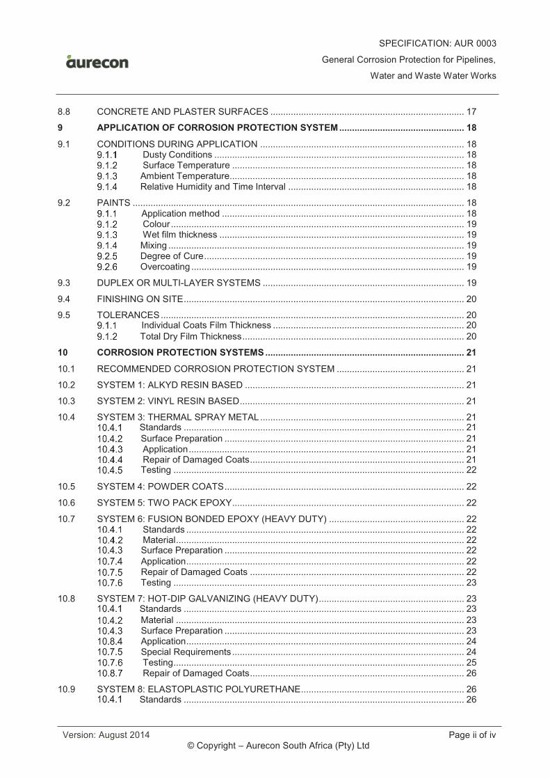
SPECIFICATION: AUR 0003
General Corrosion Protection for Pipelines,
Water and Waste Water Works
Version: August 2014 Page ii of iv © Copyright – Aurecon South Africa (Pty) Ltd
8.8 CONCRETE AND PLASTER SURFACES ............................................................................ 17
9 APPLICATION OF CORROSION PROTECTION SYSTEM ................................................. 18
9.1 CONDITIONS DURING APPLICATION ................................................................................ 18Dusty Conditions .................................................................................................. 18Surface Temperature ........................................................................................... 18
Ambient Temperature............................................................................................ 18 Relative Humidity and Time Interval ..................................................................... 18
9.2 PAINTS .................................................................................................................................. 18 Application method ............................................................................................... 18
Colour ................................................................................................................... 19Wet film thickness ................................................................................................ 19
Mixing .................................................................................................................... 19 Degree of Cure ...................................................................................................... 19 Overcoating ........................................................................................................... 19
9.3 DUPLEX OR MULTI-LAYER SYSTEMS ............................................................................... 19
9.4 FINISHING ON SITE .............................................................................................................. 20
9.5 TOLERANCES ....................................................................................................................... 20 Individual Coats Film Thickness ........................................................................... 20
Total Dry Film Thickness ....................................................................................... 20
10 CORROSION PROTECTION SYSTEMS .............................................................................. 21
10.1 RECOMMENDED CORROSION PROTECTION SYSTEM .................................................. 21
10.2 SYSTEM 1: ALKYD RESIN BASED ...................................................................................... 21
10.3 SYSTEM 2: VINYL RESIN BASED ........................................................................................ 21
10.4 SYSTEM 3: THERMAL SPRAY METAL ................................................................................ 21 Standards .............................................................................................................. 21
Surface Preparation .............................................................................................. 21Application ............................................................................................................ 21Repair of Damaged Coats .................................................................................... 21
Testing .................................................................................................................. 22
10.5 SYSTEM 4: POWDER COATS .............................................................................................. 22
10.6 SYSTEM 5: TWO PACK EPOXY ........................................................................................... 22
10.7 SYSTEM 6: FUSION BONDED EPOXY (HEAVY DUTY) ..................................................... 22Standards ............................................................................................................. 22Material ................................................................................................................. 22
Surface Preparation .............................................................................................. 22
Application ............................................................................................................. 22 Repair of Damaged Coats .................................................................................... 22 Testing .................................................................................................................. 23
10.8 SYSTEM 7: HOT-DIP GALVANIZING (HEAVY DUTY) ......................................................... 23 Standards .............................................................................................................. 23
Material ................................................................................................................. 23 Surface Preparation .............................................................................................. 23 Application ............................................................................................................. 24 Special Requirements ........................................................................................... 24
Testing .................................................................................................................. 25Repair of Damaged Coats .................................................................................... 26
10.9 SYSTEM 8: ELASTOPLASTIC POLYURETHANE ................................................................ 26 Standards .............................................................................................................. 26
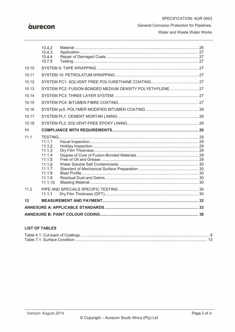
SPECIFICATION: AUR 0003
General Corrosion Protection for Pipelines,
Water and Waste Water Works
Version: August 2014 Page ii of iv © Copyright – Aurecon South Africa (Pty) Ltd
Material ................................................................................................................. 26 Application ............................................................................................................. 27 Repair of Damaged Coats .................................................................................... 27 Testing .................................................................................................................. 27
10.10 SYSTEM 9: TAPE WRAPPING ............................................................................................. 27
10.11 SYSTEM 10: PETROLATUM WRAPPING ............................................................................ 27
10.12 SYSTEM PC1: SOLVENT FREE POLYURETHANE COATING ........................................... 27
10.13 SYSTEM PC2: FUSION-BONDED MEDIUM DENSITY POLYETHYLENE .......................... 27
10.14 SYSTEM PC3: THREE LAYER SYSTEM ............................................................................. 27
10.15 SYSTEM PC4: BITUMEN FIBRE COATING ......................................................................... 27
10.16 SYSTEM pc5: POLYMER MODIFIED BITUMEN COATING ................................................ 28
10.17 SYSTEM PL1: CEMENT MORTAR LINING .......................................................................... 28
10.18 SYSTEM PL2: SOLVENT-FREE EPOXY LINING ................................................................. 28
11 COMPLIANCE WITH REQUIREMENTS ............................................................................... 29
11.1 TESTING ................................................................................................................................ 29 Visual Inspection.................................................................................................... 29 Holiday Inspection ................................................................................................. 29 Dry Film Thickness ................................................................................................ 29
Degree of Cure of Fusion-Bonded Materials ........................................................ 29 Free of Oil and Grease ......................................................................................... 29
Water Soluble Salt Contaminants ......................................................................... 30 Standard of Mechanical Surface Preparation ....................................................... 30 Blast Profile ........................................................................................................... 30
Residual Dust and Debris ..................................................................................... 30 Blasting Material ................................................................................................... 30
11.2 PIPE AND SPECIALS SPECIFIC TESTING ......................................................................... 30 Dry Film Thickness (DFT) ...................................................................................... 30
12 MEASUREMENT AND PAYMENT ........................................................................................ 32
ANNEXURE A: APPLICABLE STANDARDS ...................................................................................... 33
ANNEXURE B: PAINT COLOUR CODING .......................................................................................... 38
LIST OF TABLES
Table 4.1: Cut-back of Coatings ...................................................................................................................... 8 Table 7.1: Surface Condition ......................................................................................................................... 13
SPECIFICATION: AUR 0003
General Corrosion Protection for Pipelines,
Water and Waste Water Works
Page 1 of 40 © Copyright – Aurecon South Africa (Pty) Ltd
1 SCOPE
This Specification covers the painting and corrosion protection of plant, equipment in pump stations and water and wastewater treatment works and pipelines exposed to environments with variable corrosive tendencies.
Interpretations and variations of this Specification are set out in the Amendments of this Specification.
2 NORMATIVE REFERENCES
2.1 SUPPORTING SPECIFICATIONS
Where this Specification is required for a project, the following specifications shall, inter alia, form part of the Contract Document:
a) Amendments to this Specification;
Equipment, materials and operational methods shall comply with the latest edition of the relevant SANS, ISO,AS, BS, DIN or equivalent American Standard as shown in Annexure A.
3 DEFINITIONS AND ABBREVIATIONS
3.1 DEFINITIONS
In this Specification the following shall have the meaning given:
a) Coat: A single uniform film of corrosion protection material applied to a substrate for corrosion
protection purposes.
b) Layer: A uniform protective film of corrosion protection material applied to plant, equipment and piping
in a specified manner consisting out of multiple coats.
c) System: A corrosion protection coating or lining consisting of multiple coats and/or layers, the type of coat, the number of coats and their thickness, the method of application and the requirements of the complete system.
d) Coating: A system on the outside of plant, equipment and pipework. However, certain international
specifications referred to in this specification (e.g. AWWA specifications) use the term ‘coating’ to refer also to internal pipe protection and where these specifications are being referred to their terminology is used.
e) Lining: A system on the inside of plant, equipment and piping.
f) Dis-bonded area: An area of coating or lining that initially did adhere to the steel substrate after
application, but which subsequently became loose from the substrate as a result of mechanical, chemical or other action.
g) Un-bonded area: An area of coating or lining which at no stage adhered to the steel substrate.
h) Water path: The shortest distance along the surface of an object embedded in concrete but exposed
to water measured along the concrete interface.
i) Holiday: A discontinuity in a coating or lining which exhibits electrical conductivity when exposed to a specific voltage.
j) Abrasive blast cleaning: The process of projecting a stream of abrasive particles at high velocity towards a surface for the purpose of removing contaminants from that surface and to produce a textured surface which will increase the surface area and thus increase adhesion of the coating.
k) Dry film thickness (DFT): The thickness of a coating or lining after it is hard dry.
SPECIFICATION: AUR 0003
General Corrosion Protection for Pipelines,
Water and Waste Water Works
Page 2 of 40 © Copyright – Aurecon South Africa (Pty) Ltd
l) Electrical insulation defect (EID): Defects in a coating or lining that impair the protective
properties of the coating or lining and that are detected instrumentally by either:
i) a low-voltage, wet-sponge detector, or
ii) a high-voltage, sparking detector,
operated in each case within the parameters specified.
Note: EID's include such defects as steel projections from the substrate, conductive particles
embedded in the coatings or linings, voids and those defects commonly known as pinholes and holidays.
m) Fusion bonded epoxy (FBE): A thermoset epoxy powder coat. (The powder is normally applied by electrostatic spray to a preheated surface. The powder normally melts, fuses and cures at a temperature of 220ºC to 250ºC.)
n) Inspector: A person authorised by the Engineer to act as his representative in examining the work
and materials and drawing such samples and carrying out such tests as may be necessary to ensure compliance with the specification.
o) Lot: A number of similar or related items submitted for inspection at one time by the Contractor and of such size that the inspector can reasonably be expected to examine adequately in not more than one working day.
p) Paint: A liquid material that, when applied as a thin film to a suitably prepared surface by an
appropriate method, undergoes a physical or chemical change (or both) that converts it to a solid coating or lining bonded to the surface to which it is applied.
q) Pinhole: An electric insulation defect detected by the use of a wet sponge detector (see EID).
r) Pot life: The period, after the contents of the packs of a two-pack paint have been mixed together, during which the paint remains suitable for use without the addition of further solvent.
s) Powder coat: A material in the form of a dry, free flowing powder that, when applied to a suitably prepared steel surface by an appropriate method, can be fused by application of heat and subsequent cooling to form a continuous coating or lining that is bonded to the surface. A powder coat is classified as thermoplastic when the applied coat may be re-melted by heating, or as thermoset when it cannot be re-melted by heat. Low or medium density polyethylene powder is thermoplastic whilst FBE is a thermoset material.
t) Significant surface: The part of the article covered or to be covered by the coating or lining and for
which the coating or lining is essential for serviceability and/or appearance.
u) Steel: This term embraces carbon steels, 3CR12 and all grades of stainless steels.
v) Water break free: A surface which, when wetted all over with plain potable water, maintains a continuously wet surface and the water does not break up into islands surrounded by unwetted surfaces.
w) Wet film thickness (WFT): The thickness of a coating or lining immediately after application and
before any volatile matter has evaporated.
x) Quality control: The operational techniques and activities that are employed by the Contractor to sustain the required quality of a product, process or service.
y) SAHDGA: South African Hot Dip Galvanisers Association.
z) Sa: Followed by a number refers to a photographic illustration of the standard of blast cleaning
required, as shown in ISO 8501-1
aa) St: Followed by a number refers to a photographic illustration of the standard of mechanical cleaning
required, as shown in ISO 8501-1.
SPECIFICATION: AUR 0003
General Corrosion Protection for Pipelines,
Water and Waste Water Works
Page 3 of 40 © Copyright – Aurecon South Africa (Pty) Ltd
3.2 ABBREVIATIONS
The following abbreviations shall have the meaning assigned to them:
µm : Micrometre
3CR12 : A 12% chromium-containing corrosion resistant steel
3LPE : Three layer high density polyethylene
ABS : Acrylnitrile-butadiene-styrene
Al : Aluminium
CI : Cast iron
CS : Cast steel
DCA : Die cast aluminium
DFT : Dry film thickness
EID : Electrical insulation defect
FBE : Fusion-bonded Epoxy
FBP : Fusion-bonded Polyester
FBPE : Fusion-bonded Polyethylene
GRP : Glass fibre reinforced Polyester
HDG : Hot-dip galvanized
HDPE : High Density Polyethylene
MIO : Micaceous Iron Oxide
MS : Mild steel
PC : Polycarbonate
PVC : Polyvinylchloride
QCP : Quality Control Plan
SG : Spheroidal graphite cast iron
SS : Stainless steel – grades 304, 304L, 316 and 316L
UV : Ultra Violet
WFT : Wet film thickness
4 REQUIREMENTS
4.1 CONTRACTOR’S OBLIGATION
The requirements, material, surface preparation and corrosion protection systems prescribed in this Specification is regarded as a minimum requirement for the specific application. No deviation from this Specification shall be allowed without the written approval of the Engineer.
The Contractor is responsible for the design of the corrosion protection system and shall submit to the Engineer details of the material selection, surface preparation method and corrosion protection system he
SPECIFICATION: AUR 0003
General Corrosion Protection for Pipelines,
Water and Waste Water Works
Page 4 of 40 © Copyright – Aurecon South Africa (Pty) Ltd
intends using as part of his design, including the Manufacturer's Instructions for each product and shall only proceed with the purchase of the corrosion protection materials/paints upon receipt of conformation from the Engineer.
The Contractor shall obtain a written evidence from the chosen material manufacturer/supplier that the proposed materials, surface preparation method and corrosion protection system comply with the specified requirements and are suitable for the intended purposes under the specified Environmental Conditions (refer to Clause 4.3). The Contractor shall also obtain the Manufacturer’s Instructions (refer to Clause 4.2). The written evidence and Manufacturer’s Instructions shall be submitted to the Engineer for comment before commencement of the work.
In the event that no corrosion protection is specified for any Plant, equipment or pipes within the Specifications or Drawings, this Specification shall be used as a basis to agree on a corrosion protection system for the specific application.
4.2 MANUFACTURER’S INSTRUCTIONS
The manufacturer’s instructions shall be regarded as the recommendations supplied by the manufacturer in the form of the latest edition of printed data sheets, or given in writing on the manufacturer’s letterhead.
The following details shall be made available to the Engineer and the applicator:
· Brand and type of corrosion protection material;
· Mixing and thinning instructions;
· Recommended type and quantity of solvent required for thinning during application;
· Pot life of mixed product;
· Minimum and maximum recommended dry film thickness per coat;
· Minimum and maximum recommended dry film thickness per layer;
· Recommended time intervals between coats;
· Recommended minimum and maximum steel surface temperatures during application;
· Time for complete drying and curing on applicable surfaces;
· Substrate surface preparation requirements;
· Recommended primers for substrate;
· Recommended method of coating and lining application;
· Repair procedures for damaged coatings and/or linings and field joints on pipelines;
· Toxicity if in contact with water, and
· All relevant information the Supplier wishes to submit on his product.
Verbal instructions by the manufacturer’s representative will not be accepted unless confirmed in writing by the Contractor.
4.3 ENVIRONMENTAL CONDITIONS
Environmental conditions shall be classified according to SANS 10120-3 HC. The corrosion protection system design and applied by the Contractor shall be suitable for the Environmental Conditions specified.
Unless otherwise specified in the Amendment of this Specification the Environmental Conditions shall be classified as follows:
· Mildly-corrosive: Dry, indoor/internal, above ground and ventilated conditions, not within 5km from the coastline or polluted industrial area. Relative humidity below 70%.
· Severely corrosive: Submerged, splash-zone, underground, very moist conditions, or within 5km from coastline or polluted industrial area, or in waste water works, or close to electrical power lines. Relative humidity above 85%.
SPECIFICATION: AUR 0003
General Corrosion Protection for Pipelines,
Water and Waste Water Works
Page 5 of 40 © Copyright – Aurecon South Africa (Pty) Ltd
· Medium Corrosive: All other conditions not included in the abovementioned definitions.
Notwithstanding the abovementioned information the Contractor shall satisfy himself of the environmentalconditions on Site and design the final corrosion protection systems accordingly.
4.4 WORKMANSHIP
A high standard of workmanship is required. Only experienced personnel shall be used to carry out corrosionprotection work. All work shall be carried out under the constant supervision of a qualified supervisor.
Similarly all repair work at Site shall be done by competent personnel under the supervision of a qualified supervisor.
4.5 COMPATIBILITY OF MATERIALS
Design Precautions
All equipment shall be designed to suppress corrosion in an exposed environment with special reference to galvanic corrosion.
The Contractor shall ensure that dissimilar metals or alloys alongside each other are compatible or are adequately protected if, in the galvanic series, there is more than a 0,3 volt difference in the galvanic potential.
Galvanic Corrosion Prevention
The Contractor shall ensure that the following steps are taken to minimise corrosion:
(1) If dissimilar metals are used: Coat all surfaces of the whole assembly including the more noble member of the galvanic series.
(2) If the noble member of the assembly cannot be entirely covered:
(a) Keep the anode/cathode ratio as large as possible in the particular component.
(b) Use electrical insulators between two metals. Insulation must be complete, a bolt requires a sleeve as well as washers of an insulating material.
(3) Joints and crevices between metals shall be sealed.
(4) Where fastening is unavoidable, the fasteners shall be more noble (cathodic) than the base material. Fasteners shall be coated where possible and/or adequately electrically insulated between fasteners and the base material.
4.6 HANDLING OF CLEAN ITEMS
After cleaning, surface shall not be contaminated in any way. Operators shall wear clean gloves and all surfaces shall be clean and free from oil, grease, grit, dirt and other contamination.
4.7 MACHINED AND MATCHING SURFACES
Mating surfaces of joints shall be coated with primer (where specified) or first coat only. The coating or lining shall be uniform in thickness and shall not interfere with the mechanical tolerances. After assembly the outside surface of the joints shall be fully coated.
4.8 SPECIAL AREAS
Areas that are inaccessible after assembly shall be prepared and fully coated with the specified system to the specified requirements before assembly. The coats shall be fully cured before assembly.
Steel edges to be welded after coating shall not be coated for a distance of 50 mm from the welding edge. The unlined strip of grit blasted surface shall be temporarily protected with a coat of (red or a different colour to the lining/coating) weldable primer between coating and/or lining application and installation.
SPECIFICATION: AUR 0003
General Corrosion Protection for Pipelines,
Water and Waste Water Works
Page 6 of 40 © Copyright – Aurecon South Africa (Pty) Ltd
Friction grip areas shall be left un-coated unless otherwise specified.
4.9 SUPPORTS
During coating and/or lining application, the items shall be so supported to prevent damage to the wet coatings or linings until the coatings or linings have hardened adequately. Items shall remain supported during curing, storing and handling.
4.10 WATER RETENTION AREAS
Pockets, recesses and crevices in which water and dirt may collect shall be avoided. Water retention areas shall be properly drained by holes as large as possible.
Surfaces of corrodible metals, such as the insides of tanks or hollow Specifications that cannot be protected by any method (e.g. painting or dipping), shall be avoided, or where not possible, be fully sealed against ingress of air and moisture.
4.11 STRIPE COATS AND CREVICES
All complex surfaces including metal edges, up stands, welds, bolts and nuts shall be adequately coated to ensure complete corrosion protection. Additional stripe coats shall be applied after initial priming, if required or ordered by the Engineer.
Special attention shall be given to crevices and edges to ensure complete coverage and uniform paint thickness.
4.12 REPAIR OF DAMAGED COATS
Repair procedures shall be approved by the Engineer and repairs will be subject to inspections as set out in Clause 11.2. Where the damage is extensive the particular remedial procedures for each such instance shall be agreed with the Engineer in writing.
All repairs shall comply with the requirements of the repair-product Manufacturer’s Instructions. The Engineer may at his discretion request that repaired areas undergo adhesion tests.
Any damage occurring during transit from the Contractor’s premises to the Site shall be the responsibility of the Contractor. The Contractor shall repair any damage occurring on Site during handling, assembly, storage, transport and erection.
A repaired area shall be tested in accordance with Sub-Clauses 5.4 and 5.9 of SANS 1217 for compliance with the relevant requirements for thickness and electrical insulation defects respectively.
Any item showing electrical insulation defects exceeding an average of five per square metre (a cluster of pinholes within a radius of 25 mm being regarded as a single defective area), or flaking or other signs of loss of adhesion, shall not be repaired. The item shall be blast cleaned and re-coated in accordance with the relevant requirements of this Specification.
Paint surfaces which become streaky because paint has run, will be rejected.
Touching up of damage to the final paint coat will NOT be permitted. If final paint coat is damaged the item shall completely repainted with the finishing coat in accordance with the specifications.
Repair Methods for Minor Defects
The repair of areas showing electrical insulation defects or low film thickness shall, if approved by the Engineer, be carried out as follows:
· Degrease in accordance with Clause 7.4.1.
· Thoroughly abrade the area, including an adjacent surrounding area of at least 25 mm wide, with a medium grade 220 abrasive paper.
SPECIFICATION: AUR 0003
General Corrosion Protection for Pipelines,
Water and Waste Water Works
Page 7 of 40 © Copyright – Aurecon South Africa (Pty) Ltd
· Vacuum-clean the surface to remove dust and debris in accordance with Clause 7.2 to achieve a dust quantity rating 1 and a dust size class 0 in terms of ISO 8502-3.
· Wipe the abraded paint surface with methyl ethyl ketone and allow to dry.
· Apply as many coats of repair material as necessary to achieve the specified electrical insulation thickness and finish as to conform to the adjoining corrosion protection system’s requirements.
· Apply a final top coat over the repaired area to achieve a pleasing, uniform finish of the item.
Repair Methods for Major Defects
The repair of areas showing damage down to the steel surface shall, if approved by the Engineer, be carried out as follows:
· Degrease in accordance with Clause 7.4.1.
· Blast-clean area to Sa 3 (ISO 8501-1).
· Feather the surrounding paint for a distance of 25 mm beyond the damaged areas with a medium grade 220 abrasive paper.
· Vacuum-clean the surface to remove dust and debris in accordance with Clause to achieve a dustquantity rating 1 and a dust size class 0 in terms of ISO 8502-3.
· Wipe only the abraded paint surface with methyl ethyl ketone and allow to dry.
· Apply as many coats of repair material as necessary to conform to the specified adjoining corrosion protection system’s requirements.
· Apply a final top coat over the repaired area to achieve a pleasing, uniform finish of the item.
4.13 QUALITY CONTROL
This clause and its sub-clauses shall be read in conjunction with Specification AUR 0005 - Quality Control.
Submission for approval
The Contractor shall submit the following to the Engineer, including data sheets where applicable, forapproval:
Corrosion Protection
· A programme;
· The Quality Control Plan (QCP) for corrosion protection indicating hold points;
· Process Method Statement;
· Blast material;
· Proposed corrosion protection systems; and
· Proposed pickling and passivating products.
Manufacture and Corrosion Protection Programmes
The manufacture and corrosion protection programmes shall state the time and place when the following will be conducted:
· Inspection of material;
· Hydrostatic testing of uncoated castings, pipes and fittings;
· Manufacture of components;
· Fettling or dressing;
· Degreasing;
SPECIFICATION: AUR 0003
General Corrosion Protection for Pipelines,
Water and Waste Water Works
Page 8 of 40 © Copyright – Aurecon South Africa (Pty) Ltd
· Water soluble salts test;
· Blast cleaning and application of the first coat;
· Application of intermediate and final coats; and
· The commencement of Site repairs.
4.14 HEALTH & SAFETY REQUIREMENTS
Control of Major Classes of Risk
(1) Health risks, these include:
(a) Gases/vapours;
(b) Volatile liquids in the paint; and
(c) Powders/dust.
(2) Fire or explosion risks, these include:
(a) Fire risk during storage/transport; and
(b) Explosion hazard during application.
General Aspects of Explosion Hazards
The essential precaution to be taken is, inter alia that sufficient ventilation air shall be provided to maintain the ratio of vapour/air to no more than 10% of the lower explosive limit.
General Aspects of Toxic Hazard
Measures shall be taken by the Contractor to ensure that the following are prevented:
· Inhalation of dust/fumes;
· Skin contact with paint;
· Ingestion of paint; and
· Eye contact/penetration of paint.
Operators shall be provided with the necessary Personal Protective Equipment (PPE), such as masks/hoods, barrier creams and protective clothing to minimize the chances of the above occurring.
Emergency procedure shall be in place and First Aid kit provided to deal adequately with any of the above occurrences.
The Contractor shall ensure that in terms of Clause 6(2) of the Construction Regulations of the OH&S Act 85 of 1993, an assistant construction supervisor is specifically appointed for the application or repairs of linings inside enclosed or semi-enclosed areas e.g. pipe linings, prior to the execution of any such work.
4.15 SPECIFIC REQUIREMENTS FOR PIPES AND SPECIALS
Cut Back of Coated Pipes
The blast cleaned surface shall be stopped off or cut back by suitable masking which shall not contaminate the cleaned surface. Cut-backs shall comply with the requirements as set out in Table 4.1 below:
Table 4.1: Cut-back of Coatings
PIPE END CUT-BACK
(mm)
COMMENT
SPECIFICATION: AUR 0003
General Corrosion Protection for Pipelines,
Water and Waste Water Works
Page 9 of 40 © Copyright – Aurecon South Africa (Pty) Ltd
Pipe ends prepared for field butt welding
100 All coatings to be mitred or feathered to prevent air entrapment in the joint coating system
Pipe ends prepared for flexible joint couplings
Various The coating shall be cut back a sufficient distance to accommodate a standard coupling for the particular diameter of pipe
“Bell and spigot” pipe ends prepared for first welding
100 The cut back shall be measured from either side of the (field) external fillet weld position when the spigot is fully inserted into the “bell”
Protection of Pipe Ends on Pipes with Cut-Back
Before delivery cut backs of each pipe for field welds shall be coated with an approved rust inhibitor. This inhibitor shall provide corrosion protection for up to 6 months and shall enable good cutting and welding properties (Sigmaweld 120, Plascon etching primer or equivalent approved). Plain ended pipes (to be joined by flexible couplings) are to be coated with an approved rust inhibitor for a distance of 100mm from the pipe ends on the inside and the outside of each pipe. Careful attention must be paid to ensuring the pipe ends are also completely covered. The inhibitor used must be compatible with both the lining and the coating.
Pipe Ends
Extension of Lining
For flanged pipes or specials and pipes or specials intended for joining with flexible couplings or for Site welding by means of double sleeve weld-on couplings, the lining shall extend to the ends of pipes and specials including edges and shall overlap by at least 300 mm on the outside of the pipe. Coatings shall overlap surfaces on the outside by at least 25 mm.
Butt Weld Edges
For pipes and specials intended for Site butt-welding, lining and coating shall extend up to a distance of 50 mm from pipe ends. The unlined circumferential strip of grit blasted surface shall be temporarily protected between the Works and Site with a coat of weldable primer (of a different colour to the lining/coating).
Field Joints
No welding whatsoever shall be performed on any pipe or special on which the lining or coating has been completed, unless otherwise approved by the Engineer in writing.
The materials used for the repairs to field joints, linings and coatings shall be the same as that used for the pipes, unless otherwise approved by the Engineer in writing.
The linings and coatings of butt welded steel pipes or continuously welded steel cylinder type prestressed concrete pipes, shall be made continuous over joints as soon as possible after approval and acceptance by the Engineer of the welded joint. At no time shall field joints, lining and coating repairs/remedial work lag more than 250 metres behind the last pipe laid.
Flexible couplings shall be provided with external protection as soon as the pipeline has been hydrostatically tested and electrically bonded, where applicable.
Supports
When pipes are installed or mounted on concrete supports, rubber insertion shall be used to insulate the pipe from the support. The thickness of the rubber insertion shall not be less than 10 mm and protrude not less than 20 mm all round.
SPECIFICATION: AUR 0003
General Corrosion Protection for Pipelines,
Water and Waste Water Works
Page 10 of 40 © Copyright – Aurecon South Africa (Pty) Ltd
Sealing
Pipes that enter or exit concrete shall be sealed on their circumference with a continuous polyurethane or polysulphide flexible sealer, in a 25 mm square recess.
Spare Pipes
Corrosion protection of spare pipes shall where applicable be supplied with a top coat of Re-coatable Polyurethane to a DFT of 30 – 50 µm, colour white or silver, for storage and above ground installation.
SPECIFICATION: AUR 0003
General Corrosion Protection for Pipelines,
Water and Waste Water Works
Page 11 of 40 © Copyright – Aurecon South Africa (Pty) Ltd
5 MATERIALS
The material requirements for each corrosion protections system is specified in the relevant clauses of Clause 10 and shall be read in conjunction with this clause.
5.1 GENERAL
All materials in a corrosion protection system shall be purchased from the same manufacturer unless approved by the Engineer.
Materials offered and subsequently approved shall not be changed without written approval of the Engineer.
All corrosion protection materials shall be delivered in the manufacturer’s original containers clearly marked with the following:
· Manufacturer’s name;
· Product Brand and Reference Number;
· Batch Number which may incorporate the date of manufacture;
· Abbreviated instructions for storage and use of material, which shall include mixing ratios of the components of multi-component materials, minimum and maximum temperature of application andthe method of application; and
· The SANS mark where applicable.
Any conflict between the manufacturer's data sheet and the specification shall be referred to the Engineer for adjudication.
5.2 TOXICITY OF LINING MATERIAL
Materials used for the lining of equipment that will be in contact with water shall be non-toxic and shall notimpart any odour, taste, or colour to the water.
5.3 STORAGE
All corrosion protection materials shall be kept in an approved dry and enclosed store. The temperature shall not drop below 0°C nor exceed 40°C.
Usage of materials shall be on a first in, first out basis and no materials shall be used that have exceeded the shelf life recommended by the manufacturer.
SPECIFICATION: AUR 0003
General Corrosion Protection for Pipelines,
Water and Waste Water Works
Page 12 of 40 © Copyright – Aurecon South Africa (Pty) Ltd
6 CONTR ACTOR’S EQUIPMENT
6.1 HANDLING AND TRANSPORTATION
The plant and equipment used by the Contractor for handling of pipes, valves, pumps and other equipment, for the purpose of corrosion protection shall be such that no pipe shell, valve or pump casing or any other piece of equipment is over stressed during any operations covered by this Specification.
6.2 SURFACE PREPARATION EQUIPMENT
The Contractor shall provide all the equipment required for abrasive blast cleaning, preparation and cleaning of all surfaces to be coated.
6.3 COMPRESSOR
Compressors used for abrasive blast cleaning shall be fitted with an after cooler and oil and water traps such that the air delivered at the nozzle is completely free from oil and water. The volume displacement of the compressors shall be adequate for the number and bore of blast nozzles, the spray equipment and flame spray equipment that may be necessary to carry out the specified coating operations.
6.4 APPLICATION EQUIPMENT
The Contractor shall provide all the equipment required for airless spray painting, two component hot airless spray painting, electrostatic powder coating, fluidised bed powder coating, or any other approved method of applying the corrosion protection system in the shop or required for site application and repairs to coats. All equipment shall be thoroughly cleaned on completion of each day's work and maintained in clean working order.
6.5 INSPECTION OF EQUIPMENT
All facilities and equipment shall be subject to inspection by the Engineer or the independent inspectorate and defects in the equipment shall be rectified when so required.
6.6 INSPECTION EQUIPMENT
The Contractor shall supply all facilities and equipment for inspecting and testing the specified preparation and corrosion protection of all items supplied under the Contract. Recent calibration certificates shall be available for all equipment requiring calibration. This equipment shall be made available to the Engineer or his independent inspectorate for the purpose of testing the specified corrosion protection systems and verifying the accuracy of the test equipment.
SPECIFICATION: AUR 0003
General Corrosion Protection for Pipelines,
Water and Waste Water Works
Page 13 of 40 © Copyright – Aurecon South Africa (Pty) Ltd
7 PREPARATION OF SURFACES TO BE COATED
The surfaces of all items to be coated and/or lined, irrespective of the corrosion protection system used, shall be prepared in accordance with the relevant following requirements.
7.1 STANDARDS
Reference is made to the latest issues of the following Standards:
SANS 1344 Medium duty solvent detergent.
SANS 10064 The preparation of steel surfaces for coating.
ISO 8501-1 Preparation of steel substrates before application of paints and related products – Visual assessment of surface cleanliness – Part 1: Rust grades and preparation grades of un- coated steel substrates and of steel substrates after overall removal of previous coatings.
ISO 8502-3 Preparation of steel substrates before application of paint and related products - Tests for the assessment of surface cleanliness Part 3: Assessment of dust on steel surfaces prepared for painting (pressure-sensitive tape method)
ISO 8504-2 Preparation of steel substrates before application of paints and related products – Surface
preparation methods – Part 2: Abrasive blast cleaning.
SANS 5770 Cleanliness of blast-cleaned steel surfaces for painting (freedom of soluble salts).
SANS 5772 Profile of blast-cleaned steel surfaces for painting (profile gauge).
ISO 11125 Preparation of steel substrates before application of paints – Metallic blast-cleaning
abrasives.
ISO 11127 Preparation of steel substrates before application of paints – Non-metallic blast–cleaning abrasives.
7.2 SURFACE CONDITION
Before surface preparation all items to receive a coating or lining shall be in rust condition A to C of ISO 8501- 1. Items in rust condition D will be rejected.
Prepared surfaces shall conform to Table 7.1 below. If only surface cleanliness to ISO 8501-1 is specified in the Specifications then the corresponding values of Table 7.1 for degreasing, surface profile and soluble salts shall apply.
Table 7.1: Surface Condition
Cleanliness to ISO 8501-1 (min) Sa 3 Sa 2½ St 2
Residual dust quantity rating and size class (ISO 8502-3)
1 / 0 1 / 1 1 / 1
Oil, grease and perspiration Nil Nil Nil
Surface Profile(min)
Layers up to 200 µm (max)
30 µm
50 µm
30 µm
50 µm
n/a
Surface Profile (min) 50 µm 50 µm n/a
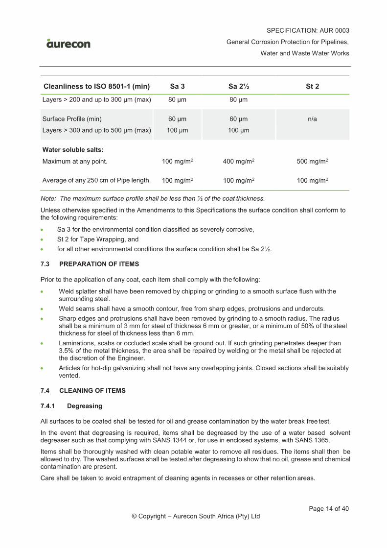
SPECIFICATION: AUR 0003
General Corrosion Protection for Pipelines,
Water and Waste Water Works
Page 14 of 40 © Copyright – Aurecon South Africa (Pty) Ltd
Cleanliness to ISO 8501-1 (min)
Sa 3
Sa 2½
St 2
Layers > 200 and up to 300 µm (max) 80 µm 80 µm
Surface Profile (min)
Layers > 300 and up to 500 µm (max)
60 µm
100 µm
60 µm
100 µm
n/a
Water soluble salts:
Maximum at any point.
Average of any 250 cm of Pipe length.
100 mg/m2
100 mg/m2
400 mg/m2
100 mg/m2
500 mg/m2
100 mg/m2
Note: The maximum surface profile shall be less than ⅓ of the coat thickness.
Unless otherwise specified in the Amendments to this Specifications the surface condition shall conform to the following requirements:
· Sa 3 for the environmental condition classified as severely corrosive,
· St 2 for Tape Wrapping, and
· for all other environmental conditions the surface condition shall be Sa 2½.
7.3 PREPARATION OF ITEMS
Prior to the application of any coat, each item shall comply with the following:
· Weld splatter shall have been removed by chipping or grinding to a smooth surface flush with the surrounding steel.
· Weld seams shall have a smooth contour, free from sharp edges, protrusions and undercuts.
· Sharp edges and protrusions shall have been removed by grinding to a smooth radius. The radius shall be a minimum of 3 mm for steel of thickness 6 mm or greater, or a minimum of 50% of the steel thickness for steel of thickness less than 6 mm.
· Laminations, scabs or occluded scale shall be ground out. If such grinding penetrates deeper than 3.5% of the metal thickness, the area shall be repaired by welding or the metal shall be rejected at the discretion of the Engineer.
· Articles for hot-dip galvanizing shall not have any overlapping joints. Closed sections shall be suitably vented.
7.4 CLEANING OF ITEMS
Degreasing
All surfaces to be coated shall be tested for oil and grease contamination by the water break free test.
In the event that degreasing is required, items shall be degreased by the use of a water based solvent degreaser such as that complying with SANS 1344 or, for use in enclosed systems, with SANS 1365.
Items shall be thoroughly washed with clean potable water to remove all residues. The items shall then be allowed to dry. The washed surfaces shall be tested after degreasing to show that no oil, grease and chemical contamination are present.
Care shall be taken to avoid entrapment of cleaning agents in recesses or other retention areas.
SPECIFICATION: AUR 0003
General Corrosion Protection for Pipelines,
Water and Waste Water Works
Page 15 of 40 © Copyright – Aurecon South Africa (Pty) Ltd
Blast Cleaning
Blast-cleaning shall be done in accordance with the code of practice SANS 10064. Any abrasive used for blast cleaning shall composed of clean, non-recycled, sound hard particles free from foreign substances such as dirt, oil, grease, toxic substances, organic matter, water soluble salts and foreign metals.
The surface of the items to be coated or lined shall be blast cleaned by centrifugal or air blast cleaning methods, then vacuum cleaned or blown off to achieve the following requirements:
· The surface condition shall be in accordance with ISO 8501-1 as stipulated in Clause 4.2 and specified in the Amendments and Additions of the Specification, when tested in accordance with SANS 5772.
· Any laminations revealed by blast cleaning shall be ground out and re-blast cleaned to meet the above requirements. If grinding penetrates the steel to a depth greater than 3.5% of the nominal wall thickness, the item will be rejected.
· The time interval between abrasive blast cleaning and paint application shall not exceed those given in Clause 9.2.6.2.
Mechanical Surface Preparation
Cleaning by hand or by means of power tools (e.g. wire brushing) shall be carried out in accordance with the methods described in SANS 10064 to the standards specified in the Amendments of this Specifications and as shown in ISO 8501-1 and Clause 7.2.
7.5 PICKLING AND PASSIVATION
Where specified the following areas shall be pickled and passivated:
· All un-coated areas;
· Ground and sheared edges; and
· Heat affected zones caused by welding or cutting.
Where possible, pickling and passivation shall be done by the dipping process.
Proprietary pickling and passivation chemicals (as supplied by approved suppliers) shall only be used in accordance with the manufacturer's recommendations. Pickling formulations made up of 15 to 20% nitric acid (HNO3) and 1 to 2% hydrofluoric acid (HF) by volume with potable water are considered suitable. Care shall be taken not to exceed the maximum contact time recommended.
After pickling and passivation, surfaces shall be very thoroughly washed with clean potable water to remove all traces of acid. Repeat the process, if necessary to remove all discolouration. Surfaces shall be allowed to dry, then polished where necessary, using polishing compounds recommended by the stainless steel manufacturer.
SPECIFICATION: AUR 0003
General Corrosion Protection for Pipelines,
Water and Waste Water Works
Page 16 of 40 © Copyright – Aurecon South Africa (Pty) Ltd
8 SURFACE PREPARATION METHODS
The requirements as specified below shall be read in conjunction with the requirements of Clause 7: Preparation of Surfaces to be Coated. Each preparation method specified below shall also conform to the relevant requirements of Clause 7 and its sub-clauses. Where in in conflict with Clause 7 and its sub-clauses the requirements hereunder shall take precedence.
Unless otherwise specified in the Amendments of this Specifications and subject to the approval of the Engineer, the surfaces of all items to be coated and/or lined shall be prepared in accordance with one or more of the following methods.
8.1 MILD STEEL
Components manufactured from mild steel shall be degreased and blast clean before the corrosion protection system is applied. Oil and grease contamination, when present, shall be removed to a water break free surface by degreasing (Refer to Clause 7.4.1) before blast cleaning (refer to Clause 7.4.2).
Steel items less than 2 mm thick may distort when blast cleaned. Sheet steel items less than 2 mm in thickness shall be degreased, acid pickled and phosphated with an approved proprietary 7 or 9 stage process to produce a fine grain zinc phosphate surface complying with SANS 10064 Table 1 Lightweight or by a proprietary process approved by the Engineer for the standard of cleaning specified.
All surfaces of steel 2 mm or more in thickness shall be abrasive blast cleaned in accordance with SANS 10064 Section 5.3 and cleaned to achieve the requirements given in Table 4.1 for the standard of abrasive blast cleaning specified.
8.2 CAST IRON AND CAST ALLOYS
Cast iron shall be abrasive blast cleaned until all sand particles, residual burnt-on sand and casting skin have been completely removed. Cast iron surfaces shall be abrasive blast cleaned in accordance with SANS 10064 Section 5.3 to achieve the requirements given in Clause 7.2 for the standard of abrasive blast cleaning specified.
Blowholes and omegas in cast surfaces shall be opened up where necessary and filled with a two component solvent free epoxy filler. When the filler has set hard, the surface shall be abraded to be flush with the surrounding metal.
8.3 STAINLESS AND CORROSION-RESISTANT STEEL
Components manufactured from stainless or corrosion-resistant steel shall be supplied in the fully passivated condition. Sheared edges, welds or surfaces subjected to any form of heat treatment or contamination with iron or mild steel, shall be pickled and passivated in terms of Clause 7.5.
Surfaces shall thereafter be thoroughly degreased in terms of Clause 7.4.1, then rinsed with potable water to obtain a water-break-free surface.
When it is required to paint stainless steel exceeding 2 mm thickness, the surface shall be blast cleaned in accordance with the parameters given in Clause 7.2, using non-metallic abrasives such as iron slag, copper slag or platinum slag. The use of steel shot, steel grit or cast-iron grit is strictly prohibited. Any contamination with iron or mild steel is prohibited.
Where blasting is impractical, the surface shall be cleaned with detergent solution and roughened manually by the use of non-metallic abrasive pads, followed by washing with clean potable water to a water-break-free surface. If a water-break-free surface is not obtained, detergent cleaning shall be repeated until the surface is water-break-free. Allow the surface to dry before coating.
SPECIFICATION: AUR 0003
General Corrosion Protection for Pipelines,
Water and Waste Water Works
Page 17 of 40 © Copyright – Aurecon South Africa (Pty) Ltd
8.4 ALUMINIUM
Not Used.
8.5 HOT-DIP GALVANIZED SURFACES
Hot-dip galvanized surfaces shall be thoroughly degreased by scrubbing with water rinsable solvent degreaser, followed by thorough washing with clean, potable water. If the water breaks up into islands of non-wetted surface, the degreasing shall be repeated until a water break free surface is obtained. Small areas may be abraded with a non-metallic abrasive paper prior to painting. Large surfaces may be sweep blast cleaned, using ultra-fine abrasive (particle size 0,2 to 0,8 mm) and a nozzle pressure not exceeding 300 kPa. A uniform matt surface shall be obtained. Loss of zinc thickness shall not exceed 10 µm. Cracking and flaking of the galvanized layer is indicative of excessive blast cleaning by using too coarse abrasive or too high blast pressure. Such surfaces will be rejected. The article shall then be stripped and re-galvanized.
8.6 PAINTED SURFACES
Primer Only
Where the surface has been contaminated it shall be washed and dried to remove dust and deposits before overcoating.
The succeeding coats shall be compatible with the primer. Where the type of primer is unknown, a test patch shall be applied. There shall be not loss of adhesion or other defects of the primer or between primer and undercoat. If defects or adhesion loss occur, the primer shall be completely removed, feather blasted and replaced by a primer which is compatible with the specified system.
Recoatable Materials
Surfaces painted with recoatable paints shall be abraded with abrasive paper grade 220 to a uniform matt finish, washed and dried to remove dust and deposits before overcoating.
Fully Cured Non-Recoatable Materials
Surfaces painted with fully cured non-recoatable paints that have exceeded their overcoating time shall be thoroughly abraded with abrasive paper grade 220 to a uniform matt finish, washed and dried before overcoating. The edges of any damage shall be smoothly feathered into the sound paint. Repairs to damaged areas shall extend 25 mm beyond the damage.
Two Component Paints within their Overcoating Time
Surfaces painted with two component paints where the paint is still within the overcoating time specified by the manufacturer shall be recoated without special surface preparation. Where the surface has become contaminated, it shall be cleaned.
8.7 PLASTIC SURFACES SUCH AS PVC AND GRP
Where the surface has been contaminated it shall be washed and dried to remove dust and deposits before overcoating.
8.8 CONCRETE AND PLASTER SURFACES
Not Used.
SPECIFICATION: AUR 0003
General Corrosion Protection for Pipelines,
Water and Waste Water Works
Page 18 of 40 © Copyright – Aurecon South Africa (Pty) Ltd
9 APPLICATION OF CORROSION PROTECTION SYSTEM
All coatings and/or linings, irrespective of the surface preparation method or corrosion protection system used, shall be applied in accordance with the relevant following requirements.
9.1 CONDITIONS DURING APPLICATION
If in the opinion of the Engineer adverse weather conditions are such as to interfere with the successful application of an efficient corrosion protective system, he shall order a stoppage of work. The Contractor will be deemed to have accepted this risk and made provision for it in his rates.
Dusty Conditions
Coats shall not be applied in dusty or contaminated conditions.
Surface Temperature
Coats shall not be applied if the surface temperature of the base metal is less than 3°C above dew point oroutside the range 5 - 40°C, unless otherwise recommended in the manufacturer’s instructions.
Ambient Temperature
Coats shall not be applied when the ambient temperature is less than the minimum or greater than the maximum recommended by the manufacturer’s instructions of the corrosion protection material.
Relative Humidity and Time Interval
The time interval between abrasive blast cleaning and paint application shall not exceed those given in Table 9.1
Table 9.1 - Maximum time interval - Between blast cleaning and coating
Ambient Relative Humidity Maximum Time (hours)
Below 50%
50% - 70%
70% - 85%
Over 85%
6
4
2
Coating not permitted -
Reblast and coat when
rel. humidity below 85%
Should immediate lining/coating not be possible, or should any atmospheric oxidisation take place between the completion of blast cleaning and commencement of lining/coating, such oxidisation shall be removed by flash blasting to restore the specified surface finish.
9.2 PAINTS
Application method
The recommendations of the paint manufacturer as per the manufacturer’s instruction (refer to Clause 4.2) as shown on his data sheets or given in writing shall be followed.
Apart from touch up, all liquid paints applied in the shop shall be applied by means of airless spray machines. Before use all paints shall be thoroughly stirred so as to be completely homogeneous. Two component paints shall be thoroughly mixed in the correct proportions as specified in the manufacturer's data sheet.
SPECIFICATION: AUR 0003
General Corrosion Protection for Pipelines,
Water and Waste Water Works
Page 19 of 40 © Copyright – Aurecon South Africa (Pty) Ltd
Painting on site shall be carried out to the Engineer's written approval. Significant surfaces to be painted on site shall be those specified in the Specification or shown on the drawings. Site application methods shall comply with the paint manufacturer's recommendations.
Colour
Successive coats shall have distinctively different shades to facilitate coverage of each coat. Unless otherwise specified in the Amendments to this Specification, or directed by the Engineer, the final paint colour shall be that given in Appendix B of this specification and shall be a commercial match to the appropriate colour in SANS 1091 - National Colour Standards for Paint.
Wet film thickness
The Contractor shall regularly and frequently monitor wet film thickness and shall calculate the dry film thickness from the volume solids of the paint.
Mixing
All paint components, particularly two- or multi-component materials, shall be thoroughly mixed until a homogeneous mixture is achieved.
Degree of Cure
The degree of cure of paint will vary with time, temperature and ventilation and shall be assessed by solvent wiping in accordance with the method given in SANS 1217 (Methyl Ethyl Ketone Resistance Test).
Overcoating
Compatibility of Coats
All primer, intermediate, finishing coats and layers shall be mutually compatible and recoatable paints shall be used where applicable. There shall be not loss of adhesion between the consecutive coats or other defects.
Overcoating intervals
The minimum and maximum overcoating intervals provided in the manufacturer's data instructions shall be strictly observed. Times and dates of application shall be recorded for each separate item and coat in the quality control records.
Since overcoating times are frequently quoted at 20 °C or 25 °C, longer overcoating times shall be allowed at lower temperatures. As a rough guide, increase time by 50% for a 5° decrease (or by 100% for a 10° decrease) in the ambient temperature below the temperature quoted in the data sheet.
Thickness of Consecutive Coats
Generally a corrosion protection system will be build-up with multiple coats. The thickness of all coats, primer, intermediate or finish coats shall be strictly according to the manufacturer’s instructions. For solvent-base paints it is imperative that the applicator does not exceed the maximum film thickness per coat applied in order to prevent entrapment of the solvent and the formation of pinholes.
9.3 DUPLEX OR MULTI-LAYER SYSTEMS
Duplex or Multi-layer systems consist of more than one corrosion protection system applied consecutively e.g. a Hot-Dip Galvanizing and Polyurethane system
SPECIFICATION: AUR 0003
General Corrosion Protection for Pipelines,
Water and Waste Water Works
Page 20 of 40 © Copyright – Aurecon South Africa (Pty) Ltd
The specifications for each of the corrosion protection systems shall be strictly followed. Special attention shall be given to adhesion between the systems.
9.4 FINISHING ON SITE
Repairs, finish painting and cleaning on the site are regarded as inherent parts of the installation. On completion of erection, all pipework, control gear and indicating gear shall be thoroughly cleaned.
After erection, paint work shall be washed down, using nylon brushes and detergent to remove all adhering contamination. It shall then be washed with clean water to remove all traces of detergent and allowed to dry. The finishing coat shall then be applied as specified in the Amendments to this Specification.
All surfaces which cannot be painted after erection shall be painted as specified before erection. The painting system so applied shall be allowed to become fully hard dry (for at least two weeks for epoxy type paints) before erection.
For coatings such as epoxies, having a limited overcoating interval as specified in the manufacturer's data sheets, the surface shall be washed and thoroughly abraded to a matt finish before application of the finishing coats in accordance with the manufacturer's instructions.
9.5 TOLERANCES
Individual Coats Film Thickness
At least 90% of all thicknesses measured shall comply with the minimum thickness of the system specification. Up to 10% of all readings may be below the specific minimum thickness, but no reading shall be less than 70% of the specified minimum thickness.
Total Dry Film Thickness
Not more than 10% of readings shall be less than the minimum specified and no reading shall be less than 90% of the specified minimum. For severely corrosive conditions no reading shall exceed the specified thickness by greater than 60% of the minimum.
SPECIFICATION: AUR 0003
General Corrosion Protection for Pipelines,
Water and Waste Water Works
Page 21 of 40 © Copyright – Aurecon South Africa (Pty) Ltd
10 CORROSION PROTECTION SYSTEMS
The requirements as specified below shall be read in conjunction with the requirements of Clause 9: Application of Corrosion Protection Systems. Each system specified below shall also conform to the relevant requirements of Clause 9 and its sub-clauses. Where the requirements of this clause is in conflict with Clause 9 and its sub-clauses the requirements hereunder shall take precedence.
10.1 RECOMMENDED CORROSION PROTECTION SYSTEM
Unless otherwise specified in the Amendments to this Specification and subject to the approval by the Engineer, Plant, equipment and pipework in pump stations and water and wastewater treatment works and pipelines shall be corrosion protected with one or more of the corrosion protection systems described in the following paragraphs of this Specification.
10.2 SYSTEM 1: ALKYD RESIN BASED
Not Used.
10.3 SYSTEM 2: VINYL RESIN BASED
Not Used.
10.4 SYSTEM 3: THERMAL SPRAY METAL
Thermally sprayed metal coatings shall consist of the metal spray plus the application of a suitable sealantand a suitable coating.
Standards
Reference is made to the latest issues of the following Standard Specifications:
SANS 2063: Thermal spraying - Metallic and other inorganic coatings - Zinc, aluminium and their alloys
Surface Preparation
The substrate surface preparation shall conform to the Manufacturer’s Instructions or as specified in the Amendments of this Specification as approved by the Engineer. In the event of it being omitted the surface preparation shall confirm to the requirements Sa 2½ (ISO 8501-1) and the corresponding requirements as specified in Table 7.1.
Application
Thermally sprayed metal coatings shall consist of the metal spray plus the application of a suitable sealant and a suitable coating.
The minimum coating thickness for both aluminium and zinc shall be 150 µm. Greater thicknesses may bespecified for particular applications.
Termal spray metal paints shall be continuously agitated in a pressure pot to ensure dispersion of the zinc particles in the liquid components.
The time between surface preparation and coating shall be shortened from 4 hours to 2 hours at any application area closer than 10 km from the coast.
Repair of Damaged Coats
The requirements of Clause 10 shall apply.
SPECIFICATION: AUR 0003
General Corrosion Protection for Pipelines,
Water and Waste Water Works
Page 22 of 40 © Copyright – Aurecon South Africa (Pty) Ltd
Testing
The thickness shall be checked on every surface plane at points not more than 300 mm apart for small articles and 500 mm for large articles. Angles shall be checked along all 4 surfaces, channels along all 6 surfaces, pipes in 4 planes. The minus tolerance on thickness in isolated areas shall also not exceed –10 % and such low areas shall not be larger than 50 mm in diameter.
10.5 SYSTEM 4: POWDER COATS
Not Used.
10.6 SYSTEM 5: TWO PACK EPOXY
Not Used.
10.7 SYSTEM 6: FUSION BONDED EPOXY (HEAVY DUTY)
This corrosion protection system is suitable for large steel items subject to medium corrosive and severly corrosive environmental conditions such as valves, pipes, etc.
Standards
Reference is made to the latest issues of the following Standards:
SANS 1217: Internal and external organic coating protection for buried steel pipelines.
ISO 12944: Paints and varnishes – Corrosion protection of steel structures by protective paint systems.
Material
Material used shall conform to SANS 1217, Type 2, powder coating.
Surface Preparation
Unless otherwise specified in the Amendments of this Specification the surface preparation shall confirm to the requirements Clause 7.2.
Application
Dry Film Thicknesses
Dry film thicknesses shall be at least 250 µm unless otherwise specified in the Amendments of this Specification
Coat Application
Items shall be heated to a temperature of 200°C (only applicable to heavy items) and coated with Fusion- bonded Epoxy by means of an electrostatic powder gun.
The normal procedures pertaining to powder application shall apply.
On completion of the coating or lining, items shall be cured for 60 minutes at 200°C (mean temperature).
Repair of Damaged Coats
Repair procedures shall be approved by the Engineer and conform to the requirements of Clause 4.12. with an approved repair kit.
SPECIFICATION: AUR 0003
General Corrosion Protection for Pipelines,
Water and Waste Water Works
Page 23 of 40 © Copyright – Aurecon South Africa (Pty) Ltd
Testing
Testing shall conform to the requirements of Clause 11 and SANS 1217.
10.8 SYSTEM 7: HOT-DIP GALVANIZING (HEAVY DUTY)
This corrosion protection system is suitable for steel items subject to mildly corrosive and medium corrosive environmental conditions such as handrails, covers, small diameter pipework, etc.
Standards
Reference is made to the latest issues of the following Standards:
SANS 32: See EN 10240.
SANS 121: Hot-dip galvanized coatings on fabricated iron and steel articles.
SANS 1344: Medium duty solvent detergent.
SANS 2063: Thermal spraying - Metallic and other inorganic coatings - Zinc, aluminium and their alloys.
SANS 5772: Profile of blast-cleaned steel surfaces for painting.
ISO 752: Zinc ingots.
ISO 2808: Paints and varnishes - Determination of film thickness.
ISO 14713: Protection against corrosion of iron and steel in structures - Zinc and aluminium coatings - Guidelines.
EN 1179: Zinc and zinc alloys – primary zinc.
EN 10240: Internal and/or external protective coatings for steel tubes - Specification for hot dip galvanized coatings applied in automatic Plants
Material
Impurities in the molten zinc, as defined in ISO 752 and EN 1179, shall not exceed a total of 1.5%.
Steel to be hot-dip galvanized shall be as listed below. In both cases material certification shall be supplied:
· For aesthetic appearance:
- Aluminium killed steel, or
- Silicon-killed steel with a Silicon content not exceeding 0.04% and a Phosphorus content not exceeding 0.02%.
· For general corrosion protection:
- Aluminium killed steel, or
- Silicon killed steel with a Silicon content not exceeding 0.25% and a Phosphorus content not exceeding 0.02%.
The condition of articles to be hot-dip galvanized shall comply with Clause 7.3 of SANS 121.
The condition of tubes to be hot-dip galvanized on a continuous line shall comply with “Annexure A” of EN 10240.
Surface Preparation
Unless otherwise specified in the Amendments of this Specification the surface preparation shall confirm to the requirements Clause 7.2.
SPECIFICATION: AUR 0003
General Corrosion Protection for Pipelines,
Water and Waste Water Works
Page 24 of 40 © Copyright – Aurecon South Africa (Pty) Ltd
Application
Galvanizing shall only be done by members of the Hot Dip Galvanizers Association of Southern Africa (HDGASA) in accordance with SANS 121 and EN 10240.
The coating of lining thickness shall comply with the values specified for General Applications or Heavy Duty Applications as specified in this Specification.
Galvanized surfaces which are to be painted shall NOT be passivated by the galvanizer.
Special Requirements
Steel Specials
(1) Surface
Surfaces shall be free from nodules, blisters, roughness and sharp points. Un-coated areas, flux residues, lumps and zinc ash will not be permitted.
Notwithstanding Clause 6.1 of SANS 121, in the case of handrails etc. a high quality surface finish is required and a bright smooth surface shall be achieved. Double dipping shall not be allowed.
(2) Thickness
The thickness of hot-dip galvanizing shall comply with the requirements of the Table 10.1 below.
Table 10.1: System 7 - Minimum Coat Thickness on Items that are not Centrifuged
ARTICLES AND ITS THICKNESS
HEAVY DUTY LIGHT DUTY
Thickness µm (min)
Local Thickness µm (min)
Mean Thickness µm (min)
Steel ³ 6 mm 105 70 85
3.0 mm £ Steel < 6.0 mm 80 55 70
1.5 mm £ Steel < 3.0 mm 65 45 55
Steel < 1.5 mm 55 35 45
Castings ³ 6.0 mm 105 70 80
Castings < 6.0 mm - 60 70
Heavy duty coats are required except in the following cases:
· Where a high surface finish is required; and
· Where otherwise specified in the Amendments of this Specification.
Steel Tubes
Steel tubes shall be in accordance with Clause 7 of EN 10240.
(3) Surface
The surface of the coat shall be continuous, smooth and free from flux residues.
(4) Thickness
The thickness shall comply with the requirements of the coat quality A1, in accordance with Clause 8, Table 1 of EN 10240, as specified below.
SPECIFICATION: AUR 0003
General Corrosion Protection for Pipelines,
Water and Waste Water Works
Page 25 of 40 © Copyright – Aurecon South Africa (Pty) Ltd
Table 10.2: System 7 - Minimum Local Coat Thickness Requirements for Coat Quality A1
REQUIREMENTS QUALITY A1
Minimum local coat thickness on the inside surface except at the weld bead
55 µm
Minimum local coat thickness on the inside surface at the weld bead
28 µm
Minimum local coat thickness on the outside surface
55 µm
(5) Adhesion
The coat shall show no evidence of flaking or cracking when tested in accordance with
Clause 11.4 of EN 10240.
(6) Qualities
Coat qualities shall be A1 for water installations – see Sub-Clause 8.2 of EN 10240.
The surface of the coat on the inside shall be as smooth as can be achieved by steam blowing.
Testing
This clause and its sub-clauses shall be read in conjunction with Clause 4.13 and Clause 11.1 of this Specification.
Steel Items
(7) Visual Examination
Where a superior aesthetic appearance of hot-dip galvanizing is requested, a bright mirror surface finish shall be achieved by the galvanizer.
(8) Thickness
Thicknesses shall be in accordance with Clause 10.8.5 and shall be tested in accordance with Sub-Clause 6.2 of SANS 121.
Steel Tubes
(9) Visual Examination
Where a superior aesthetic appearance of hot-dip galvanizing is requested, a bright mirror surface finish shall be achieved by the galvanizer.
(10) Thickness
Shall be tested in accordance with Sub-Clause 11.3 of EN 10240 (SANS 32).
(11) Adhesion
Shall be tested in accordance with Sub-Clause 11.4 of EN 10240 (SANS 32).
Chemical Analysis
Items shall be tested in accordance with Sub-Clause 11.5 of EN 10240 (SANS 32).
SPECIFICATION: AUR 0003
General Corrosion Protection for Pipelines,
Water and Waste Water Works
Page 26 of 40 © Copyright – Aurecon South Africa (Pty) Ltd
Repair of Damaged Coats
General
Repairs to damaged galvanizing shall be carried out in accordance with the procedures specified in SANS 121 by hot metallic zinc spraying unless the use of an appropriate solder is approved. Conventional solder shall NOT be used. Solder composition shall have been approved in writing by the SANS (Metallurgy Division) or by the SAHDGA.
Steel Items
The total un-coated areas for renovation by the galvanizer shall not exceed 0.5% of the total surface area of a component. Each un-coated area for renovation shall not exceed 400 mm². If un-coated areas are larger, the item containing such areas shall be re-galvanized.
The repair method shall be approved by the Engineer before repairs are initiated.
Repairs shall be by zinc thermal spray in accordance with SANS 2063 or three component zinc solvent free Epoxy repair system. The repair shall include removal of any scale, cleaning and any necessary pre- treatment to ensure adhesion – refer to Clause 7
The coat thickness on the renovated areas shall be a minimum of 30 µm more than the local coat thickness specified in Clause 10.8.5 for the relevant hot-dip galvanized coat unless otherwise specified by the Engineer. The coat on the renovated areas shall be capable of giving sacrificial protection to the steel to which it is applied.
Steel Tubes
Repairs shall not be allowed on internal surfaces of tubes. Where repairs are required, tubes shall be re-galvanized. Repairs on external surfaces shall be in accordance with Clause 10.8.7.1.
10.9 SYSTEM 8: ELASTOPLASTIC POLYURETHANE
This part of the Specification applies to two component solvent free elastoplastic polyurethane. This system shall only be used in limited approved applications.
Standards
Reference is made to the latest issues of the following Standards:
SANS1217: Internal and external organic coating protection for buried steel pipelines.
Material
The paint material shall be a solvent free two-component polyurethane hybrid based on a polyester type polyol and aromatic isocyanate. The cured paint shall comply with the following requirements:
· Tensile strength at 3 mm thickness - ASTM D638 - not less than 15 MPa.
· Adhesion to primed steel - SANS Method 776 - not less than 10 MPa.
· Impact resistance (direct) - ASTM G14 - not less than 9 Joules.
· Dielectric Strength - not less than 10 kV/mm.
· Elongation at break - not less than 25%.
· Compressibility - not less than 25 MPa.
· Surface hardness of 5 mm thick sample - not less than 60 nor greater than 80 Shore 'D'.
· Water Vapour Permeability - not greater than 0.5 g/24 h/m²/mm².
SPECIFICATION: AUR 0003
General Corrosion Protection for Pipelines,
Water and Waste Water Works
Page 27 of 40 © Copyright – Aurecon South Africa (Pty) Ltd
· Cathodic disbonding - when tested in accordance with ASTM G8 Method A, for 60 days, the dis- bonded area shall not exceed 500 mm².
Adhesive
Adhesive shall be a two component polyurethane adhesive designed to maximise adhesion between used polyurethane and freshly mixed polyurethane.
Application
Dry Film Thicknesses
Dry film thicknesses shall be at least as follows unless otherwise specified in the Amendments of this Specification
· Overcoating as duplex system
- The dry film thickness shall be 40 µm minimum.
· For corrosive/abrasive environmental conditions:
- The dry film thickness shall be 1.0 mm minimum.
· For highly corrosive/abrasive environmental conditions:
- The dry film thickness shall be 3.0 mm minimum.
Repair of Damaged Coats
Repair procedures shall be approved by the Engineer and conform to the requirements of Clause 4.12.
Testing
Testing shall conform to the requirements of Clause 11 and SANS 1217.
10.10 SYSTEM 9: TAPE WRAPPING
Not Used.
10.11 SYSTEM 10: PETROLATUM WRAPPING
Not Used.
10.12 SYSTEM PC1: SOLVENT FREE POLYURETHANE COATING
Not Used.
10.13 SYSTEM PC2: FUSION-BONDED MEDIUM DENSITY POLYETHYLENE
Not Used.
10.14 SYSTEM PC3: THREE LAYER SYSTEM
Not Used.
10.15 SYSTEM PC4: BITUMEN FIBRE COATING
Not Used.
SPECIFICATION: AUR 0003
General Corrosion Protection for Pipelines,
Water and Waste Water Works
Page 28 of 40 © Copyright – Aurecon South Africa (Pty) Ltd
10.16 SYSTEM PC5: POLYMER MODIFIED BITUMEN COATING
Not Used.
10.17 SYSTEM PL1: CEMENT MORTAR LINING
Not Used.
10.18 SYSTEM PL2: SOLVENT-FREE EPOXY LINING
Not Used.
SPECIFICATION: AUR 0003
General Corrosion Protection for Pipelines,
Water and Waste Water Works
Page 29 of 40 © Copyright – Aurecon South Africa (Pty) Ltd
11 COMPLIANCE WITH REQUIREMENTS
11.1 TESTING
Tests, instruments, methods and criteria shall be as specified below or in the Amendments of this Specification.
The requirements of Clauses 4.13 shall apply.
Visual Inspection
All surfaces shall be inspected visually and shall be free from tears, runs, sags, wrinkles, blisters, change in colour or gloss, orange peel, dirt, visible pinholes, dust or fluff occlusions or any other visible defects.
Holiday Inspection
100% of all coated surfaces shall be tested and there shall be no electrical insulation defects on any area inspected.
For films exceeding 500 µm thickness, a high voltage, electrical insulation defects detector shall be used in accordance with SABS 1217.
Except on system containing conductive pigment (Zn, Al), low-voltage wet sponge electrical insulation defects inspection shall be carried out in accordance with SANS 1217 for coatings and linings of thickness not exceeding 500 µm.
For systems exceeding 500 µm thickness, the high voltage, sparking electrical insulation defects detector shall be used in accordance with SANS 1217.
During the inspection procedure the Contractor shall ensure that sufficient moisture is present at all times on the surfaces to be tested.
Dry Film Thickness
The dry film thickness (DFT) shall also conform to the requirements of Clause 9.5
(a) Measurements shall be taken in accordance with ISO 2808.
(b) 100% of all system thicknesses measured shall comply with the minimum requirements of this Specification.
(c) Film thickness in excess of the prescribed maxima shall not necessarily constitute reason for rejection if the system is demonstrated to be sound in all respects.
(d) The method used to measure film thickness, and the significance of the readings for each particular project, shall be agreed upon by all parties prior to commencement of the work.
Degree of Cure of Fusion-Bonded Materials
The degree of cure of corrosion protection material shall be assessed by solvent wiping in accordance with the method given in SABS 1217 (methyl ethyl ketone resistance test)
Free of Oil and Grease
Wetting with Water
All surfaces cleaned of oil and grease shall be tested using the “water-break-free” method. The surface shall be wetted with water and the entire surface shall be covered by an unbroken film.
SPECIFICATION: AUR 0003
General Corrosion Protection for Pipelines,
Water and Waste Water Works
Page 30 of 40 © Copyright – Aurecon South Africa (Pty) Ltd
Solvent-Wiping
Where water soluble lubricants may be present the surface shall be further tested by wiping with a clean cotton wool swab soaked in solvent. No stain shall be evident on the swab after solvent-wiping.
Water Soluble Salt Contaminants
Substrate surfaces shall be tested for the presence of water soluble salt contaminants in accordance with SANS 5770 or by means of the Weber Reilly Test.
Standard of Mechanical Surface Preparation
Mechanical surface preparation shall be visually compared to the standard shown in SABS ISO 8501-1.
Blast Profile
The blast profile of the substrate surfaces shall be determined in accordance with SANS 5772.
Residual Dust and Debris
Substrate surfaces shall be tested for the presence of residual dust and debris in accordance with ISO 8502- 3.
Blasting Material
All blasting-materials shall be approved by the Engineer.
Metallic Abrasive
Abrasive shall be tested in accordance with ISO 11125 for particle size, hardness, density, foreign matter and moisture.
Non-Metallic Abrasive
Abrasive shall be tested in accordance with ISO 11127 for particle size, hardness, density, moisture and water soluble contaminants.
11.2 PIPE AND SPECIALS SPECIFIC TESTING
Dry Film Thickness (DFT)
Measurements shall be taken in accordance with ISO 2808.
100% of all system thicknesses measured shall comply with the minimum requirements of this Specification.
In the case of coats applied after the erection of steel work on Site, the frequency at which measurements of the DFT are taken shall be at the discretion of the Engineer, and may be dictated by accessibility.
DFT in excess of the prescribed maxima shall not necessarily constitute reason for rejection if the paint film is demonstrated to be sound in all respects.
DFT shall be tested within 7 days of application.
The method used to measure DFT, and the significance of the readings for each particular item, shall be agreed upon by all parties prior to commencement of the coating work.
SPECIFICATION: AUR 0003
General Corrosion Protection for Pipelines,
Water and Waste Water Works
Page 31 of 40 © Copyright – Aurecon South Africa (Pty) Ltd
Automated Shop Applied Lining and Coating
The film thickness on the first pipe of a production run and thereafter on at least one pipe selected at random from every day's production, but not less than one pipe out of every ten pipes, shall be measured non- destructively by an approved eddy current instrument. At least four readings at equally spaced intervals around the circumference, approximately 300 mm from each end of the pipe, shall be taken. The first reading shall be over the weld bead. When practicable an additional four readings at equally spaced intervals around the circumference in the centre of the pipe shall be taken. The thickness shall not be less than the minimum specified over 100% of the area including weld beads. The Engineer may at his discretion supplement the above test by checking wet film thickness on any or all pipes during application of the coats.
Hand and In-situ Applied Lining and Coating
All the hand applied lining and coating thicknesses shall be tested by means of an approved eddy current or magnetic instrument. At least four readings shall be taken at equally spaced intervals around the pipe circumference at any test point. The first reading shall be over the weld bead. The thickness shall not be less than the minimum specified over 100% of the area including weld beads.