Embed Size (px)
Citation preview
Page 1
SPECIFICATION FOR TFT LCD MODULE
MODEL NO:FC-T28QHI01T1
CUSTOMER: ___________
(FC-T28QHI01T1) This module uses ROHS material
Customer Approval: □ Approve Specification Only □ Approve Specification and Sample
ISSUED DATE: 2012-4-15
PREPARED CHECKED LX APPROVED LX
APPROVED
DATE:
Page 2
Records of Revision
DATE REF.PAGE PARAGRAPH DRAWING No.
REVISED No.
SUMMARY REMARK
2012-4-15 ALL 00 FIRST ISSUE
Page 3
Contents
1 Introduction---------------------------------------------------------------------------------- 4
2 General specification-------------------------------------------------------------------- 5
3 Mechanical drawing---------------------------------------------------------------------- 6
4 Absolute maximum ratings------------------------------------------------------------- 7
5 Electrical characteristics----------------------------------------------------------------- 7
6 Touch Panel specifications ------------------------------------------------------------ 8
7 Optical characteristics ------------------------------------------------------------------ 9
8 Pin Assignment ----------------------------------------------------------------------------- 12
9 Block diagram ------------------------------------------------------------------------------ 13
10 LCM quality criteria------------------------------------------------------------------------ 14
11 Packing method---------------------------------------------------------------------------- 21
Page 4
1. Introduction
1.1 Scope of application This specification applies to the Negative type TFT transmissive dot matrix LCD module that is supplied FC OPTOELECTTRONICS. This LCD module should be designed for mobile phone use. LCD specification: Dots 240xRGBx320. As to basic specification of the driver IC, refer to the IC (ILI9341 ) specification and datasheet.
1.2 Structure:
Double display structure: TFT Module + FPC + Touch Panel +BL FULL 65k or 262k Color 2.8 inch TFT LCD size for main LCD; One bare chip with gold bump (COG) TECH; 16/8 BITS 80 parallel and RGB interface;
1.3 TFT features: Structure: TFT PANNEL+IC+FPC+BL+TP; Transmissive Type LCD 240 dot-source and 320 dot-gate outputs; 65k or 262k Color can be selected by software; White LED back light; 16/8 BITS 80 parallel interface;
1.4 Applications: Mobile phone
PSP PDA GPS Etc…
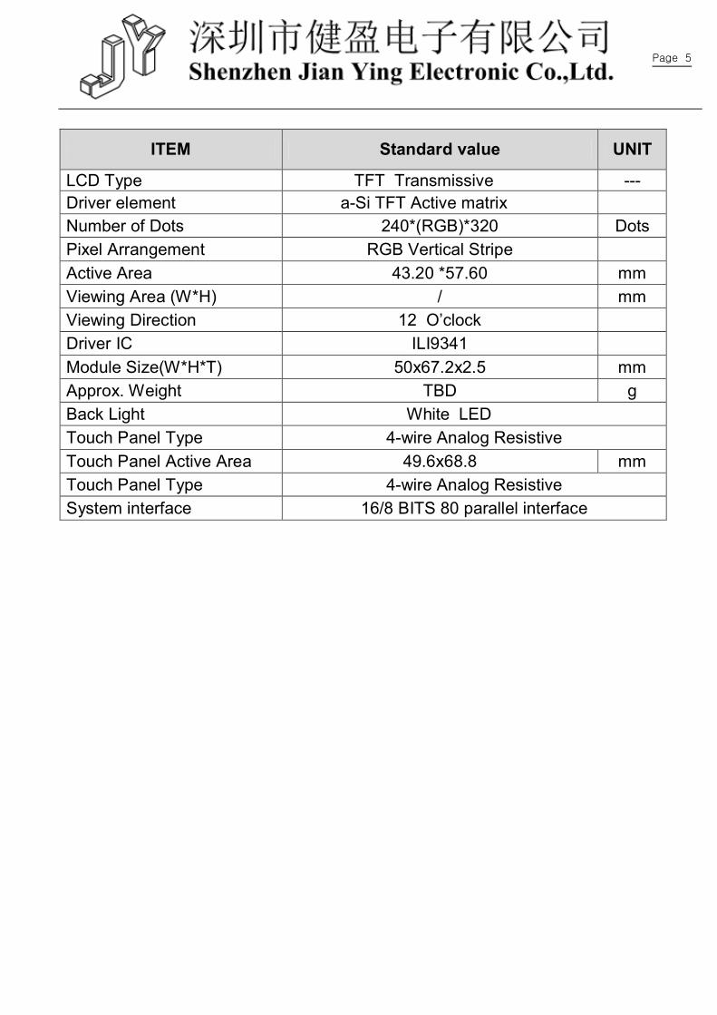
2. General specification
Page 5
ITEM Standard value UNIT
LCD Type TFT Transmissive --- Driver element a-Si TFT Active matrix Number of Dots 240*(RGB)*320 Dots Pixel Arrangement RGB Vertical Stripe Active Area 43.20 *57.60 mm Viewing Area (W*H) / mm Viewing Direction 12 O’clock Driver IC ILI9341 Module Size(W*H*T) 50x67.2x2.5 mm Approx. Weight TBD g Back Light White LED Touch Panel Type 4-wire Analog Resistive Touch Panel Active Area 49.6x68.8 mm Touch Panel Type 4-wire Analog Resistive System interface 16/8 BITS 80 parallel interface
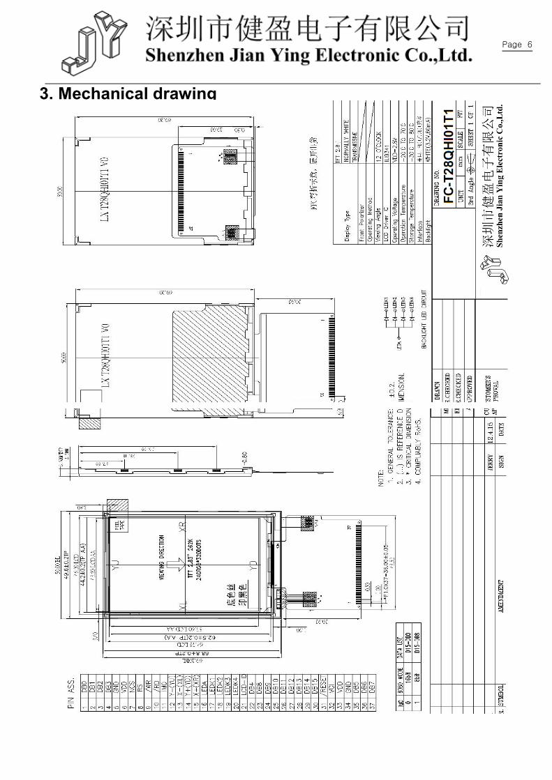
Page 6
3. Mechanical drawing
Page 7
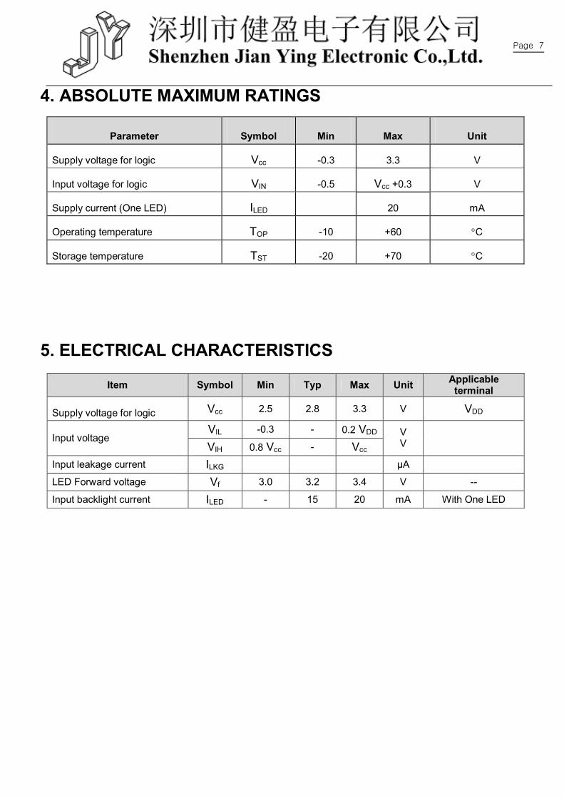
4. ABSOLUTE MAXIMUM RATINGS
Parameter Symbol Min Max Unit
Supply voltage for logic Vcc -0.3 3.3 V
Input voltage for logic VIN -0.5 Vcc +0.3 V
Supply current (One LED) ILED 20 mA
Operating temperature TOP -10 +60 C
Storage temperature TST -20 +70 C
5. ELECTRICAL CHARACTERISTICS
Item Symbol Min Typ Max Unit Applicable terminal
Supply voltage for logic Vcc 2.5 2.8 3.3 V VDD
VIL -0.3 - 0.2 VDD Input voltage
VIH 0.8 Vcc - Vcc V V
Input leakage current ILKG μA
LED Forward voltage Vf 3.0 3.2 3.4 V --
Input backlight current ILED - 15 20 mA With One LED
Page 8
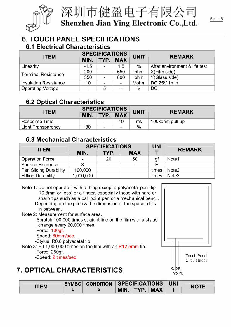
6. TOUCH PANEL SPECIFICATIONS 6.1 Electrical Characteristics
SPECIFICATIONS ITEM MIN. TYP. MAX UNIT REMARK Linearity -1.5 - 1.5 % After environment & life test
200 - 650 ohm X(Film side) Terminal Resistance 350 - 800 ohm Y(Glass side) Insulation Resistance 10 - - Mohm DC 25V 1min Operating Voltage - 5 - V DC
6.2 Optical Characteristics
SPECIFICATIONS ITEM MIN. TYP. MAX UNIT REMARK Response Time - - 10 ms 100kohm pull-up Light Transparency 80 - - %
6.3 Mechanical Characteristics SPECIFICATIONS ITEM MIN. TYP. MAX
UNIT REMARK
Operation Force - 20 50 gf Note1 Surface Hardness 3 - - H Pen Sliding Durability 100,000 times Note2 Hitting Durability 1,000,000 times Note3 Note 1: Do not operate it with a thing except a polyacetal pen (tip
R0.8mm or less) or a finger, especially those with hard or sharp tips such as a ball point pen or a mechanical pencil.
Depending on the pitch & the dimension of the spacer dots in between.
Note 2: Measurement for surface area. -Scratch 100,000 times straight line on the film with a stylus
change every 20,000 times. -Force: 100gf. -Speed: 60mm/sec. -Stylus: R0.8 polyacetal tip. Note 3: Hit 1,000,000 times on the film with an R12.5mm tip. -Force: 250gf. -Speed: 2 times/sec.
7. OPTICAL CHARACTERISTICS
SPECIFICATIONS ITEM SYMBOL
CONDITIONS MIN. TYP. MAX
UNIT NOTE
XL XRYD YU
Touch PanelCircuit Block
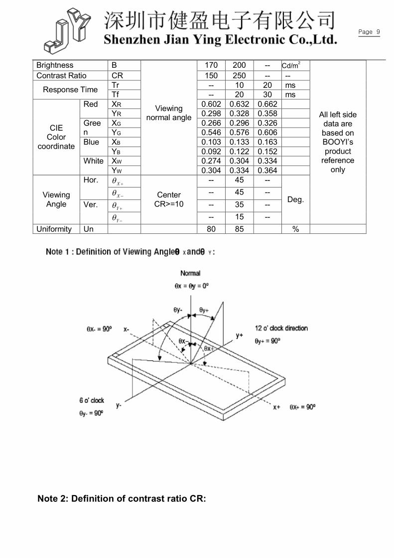
Page 9
Brightness B 170 200 -- Cd/m2
Contrast Ratio CR 150 250 -- --
Tr -- 10 20 ms Response Time Tf -- 20 30 ms XR 0.602 0.632 0.662 Red YR 0.298 0.328 0.358 XG 0.266 0.296 0.326 Gree
n YG 0.546 0.576 0.606 XB 0.103 0.133 0.163 Blue YB 0.092 0.122 0.152 XW 0.274 0.304 0.334
CIE Color
coordinate
White YW
Viewing normal angle
0.304 0.334 0.364 X -- 45 -- Hor.
X -- 45 --
Y -- 35 -- Viewing Angle Ver.
Y
Center CR>=10
-- 15 --
Deg.
All left side data are based on BOOYI’s product
reference only
Uniformity Un 80 85 %
Note 2: Definition of contrast ratio CR:
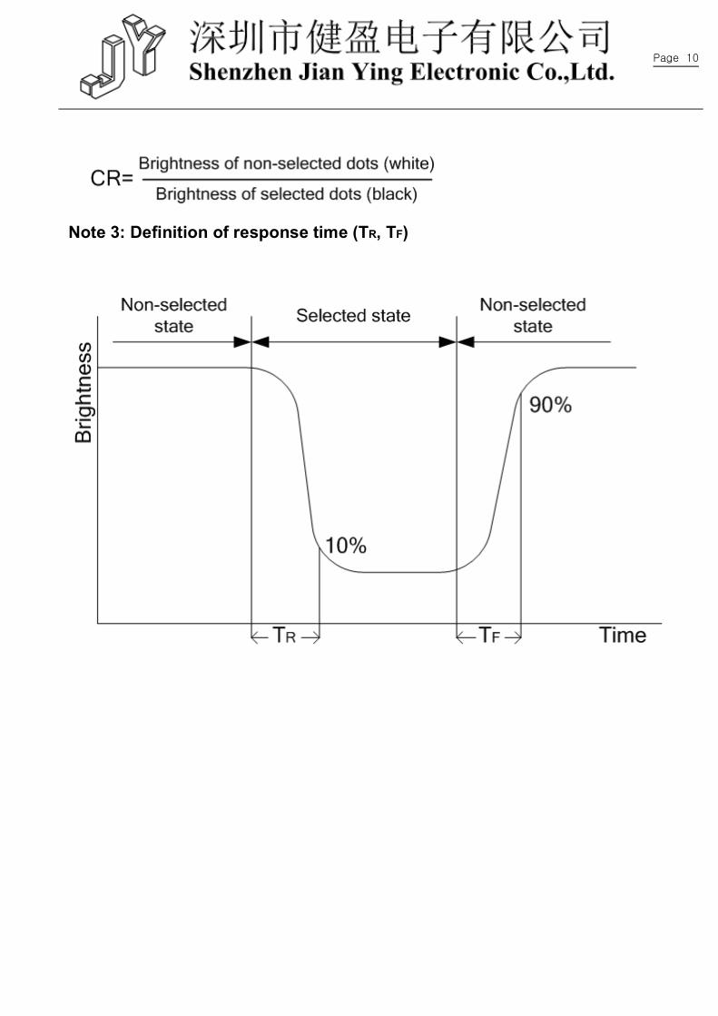
Page 10
Note 3: Definition of response time (TR, TF)
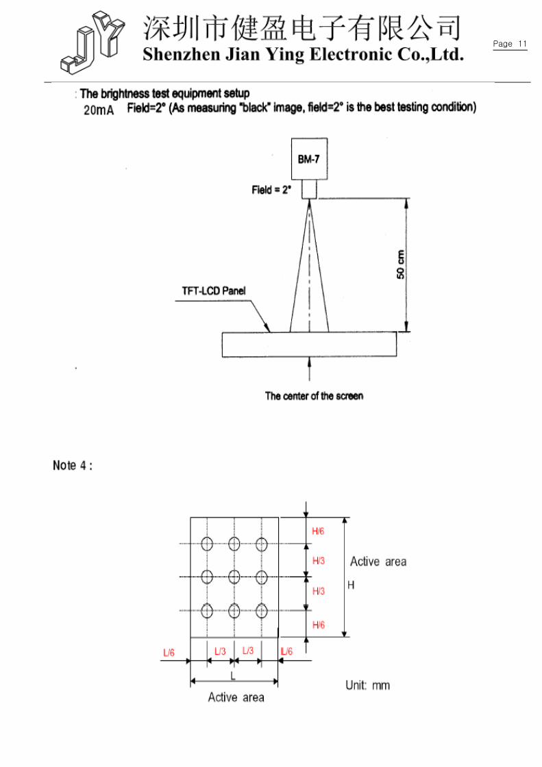
Page 11
Page 12
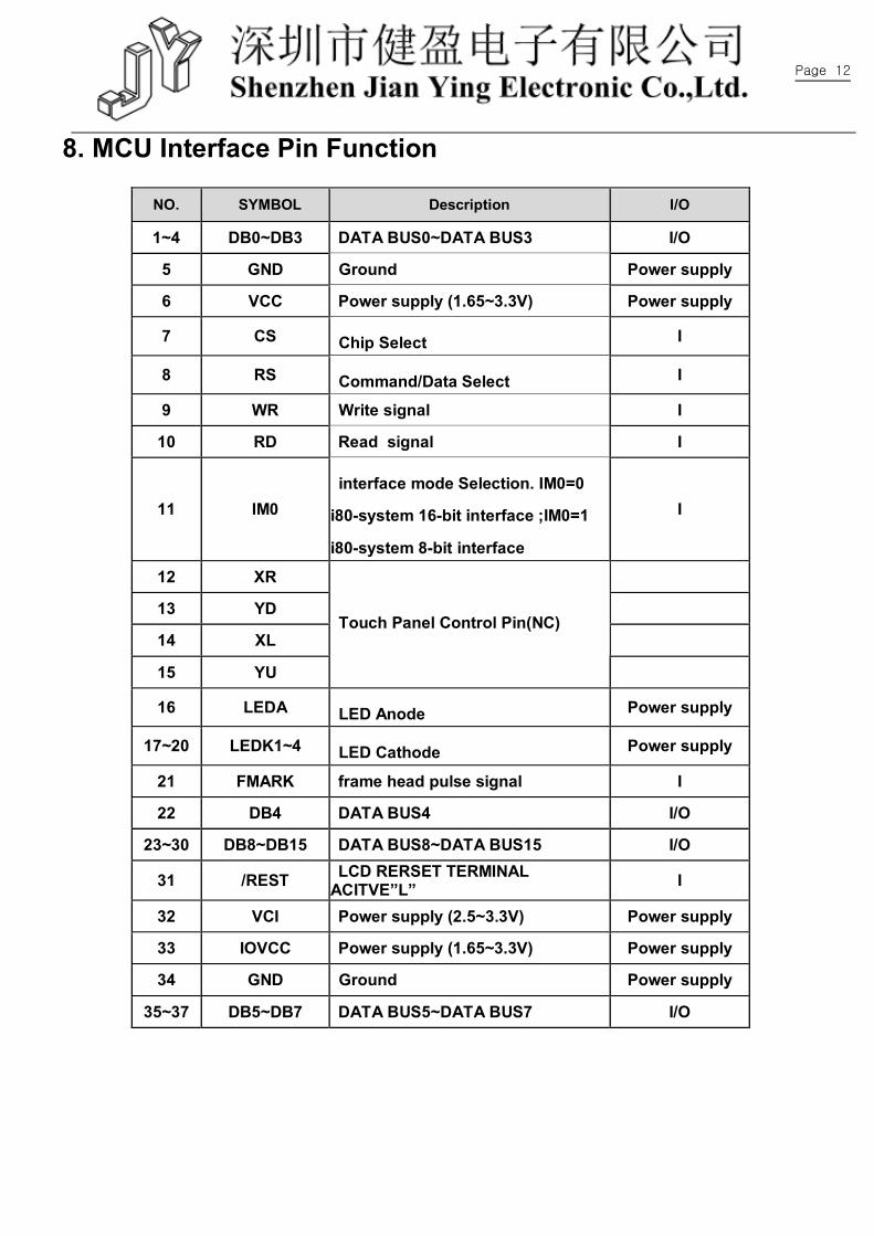
8. MCU Interface Pin Function
NO. SYMBOL Description I/O
1~4 DB0~DB3 DATA BUS0~DATA BUS3 I/O
5 GND Ground Power supply
6 VCC Power supply (1.65~3.3V) Power supply
7 CS Chip Select I
8 RS Command/Data Select I
9 WR Write signal I
10 RD Read signal I
11 IM0 interface mode Selection. IM0=0
i80-system 16-bit interface ;IM0=1
i80-system 8-bit interface
I
12 XR
13 YD
14 XL
15 YU
Touch Panel Control Pin(NC)
16 LEDA LED Anode Power supply
17~20 LEDK1~4 LED Cathode Power supply
21 FMARK frame head pulse signal I
22 DB4 DATA BUS4 I/O
23~30 DB8~DB15 DATA BUS8~DATA BUS15 I/O
31 /REST LCD RERSET TERMINAL ACITVE”L” I
32 VCI Power supply (2.5~3.3V) Power supply
33 IOVCC Power supply (1.65~3.3V) Power supply
34 GND Ground Power supply
35~37 DB5~DB7 DATA BUS5~DATA BUS7 I/O
Page 13
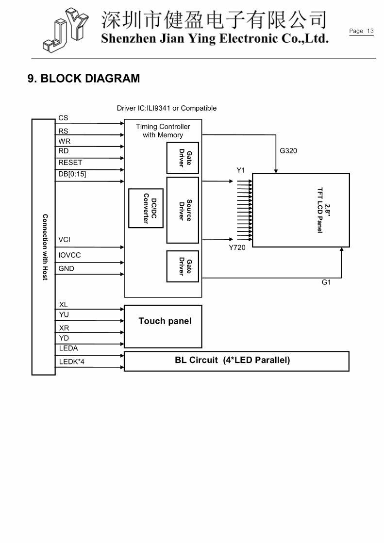
9. BLOCK DIAGRAM
Connection w
ith Host
Timing Controller with Memory
Driver IC:ILI9341 or Compatible
Gate
Driver
DC
/DC
C
onverter
Source D
river G
ate D
river
2.8” TFT LC
D Panel
CS
Y1
RS WR RD
DB[0:15] RESET
IOVCC
G320
Y720
G1
GND
VCI
BL Circuit (4*LED Parallel)
Touch panel
XL
XR
YU
YD LEDA
LEDK*4
Page 14
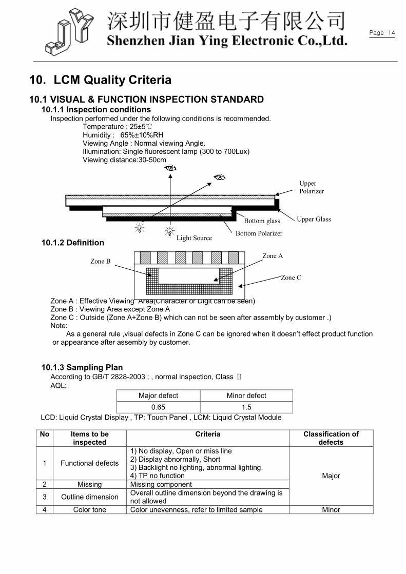
10. LCM Quality Criteria 10.1 VISUAL & FUNCTION INSPECTION STANDARD
10.1.1 Inspection conditions Inspection performed under the following conditions is recommended.
Temperature : 25±5℃ Humidity : 65%±10%RH Viewing Angle : Normal viewing Angle. Illumination: Single fluorescent lamp (300 to 700Lux) Viewing distance:30-50cm
10.1.2 Definition
Zone A : Effective Viewing Area(Character or Digit can be seen) Zone B : Viewing Area except Zone A Zone C : Outside (Zone A+Zone B) which can not be seen after assembly by customer .) Note: As a general rule ,visual defects in Zone C can be ignored when it doesn’t effect product function or appearance after assembly by customer.
10.1.3 Sampling Plan According to GB/T 2828-2003 ; , normal inspection, Class Ⅱ AQL:
Major defect Minor defect 0.65 1.5
LCD: Liquid Crystal Display , TP: Touch Panel , LCM: Liquid Crystal Module
No Items to be inspected
Criteria Classification of defects
1 Functional defects
1) No display, Open or miss line 2) Display abnormally, Short 3) Backlight no lighting, abnormal lighting. 4) TP no function
2 Missing Missing component
3 Outline dimension Overall outline dimension beyond the drawing is not allowed
Major
4 Color tone Color unevenness, refer to limited sample Minor
Upper Glass
Upper Polarizer
Bottom glass
Bottom Polarizer Light Source
Zone A Zone B
Zone C
Page 15
5 Soldering appearance
Good soldering , Peeling off is not allowed.
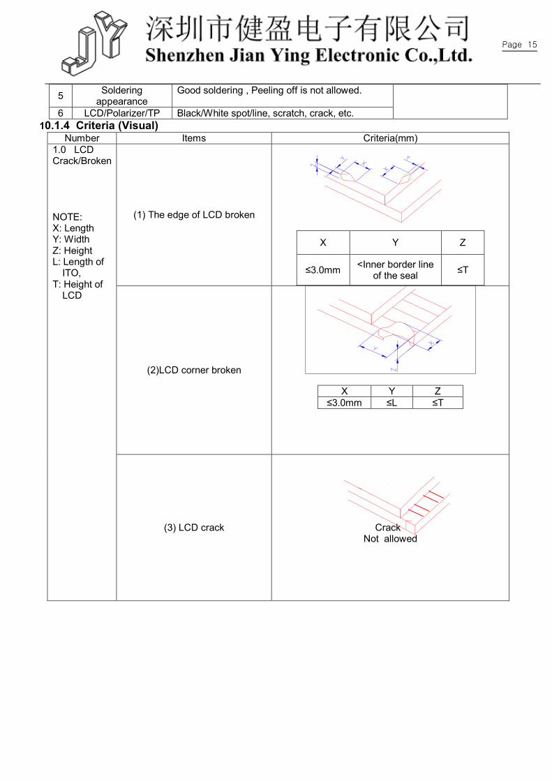
6 LCD/Polarizer/TP Black/White spot/line, scratch, crack, etc. 10.1.4 Criteria (Visual)
Number Items Criteria(mm)
(1) The edge of LCD broken
X Y Z
≤3.0mm <Inner border line of the seal ≤T
(2)LCD corner broken
X Y Z ≤3.0mm ≤L ≤T
1.0 LCD Crack/Broken NOTE: X: Length Y: Width Z: Height L: Length of
ITO, T: Height of
LCD
(3) LCD crack
Crack Not allowed
Page 16
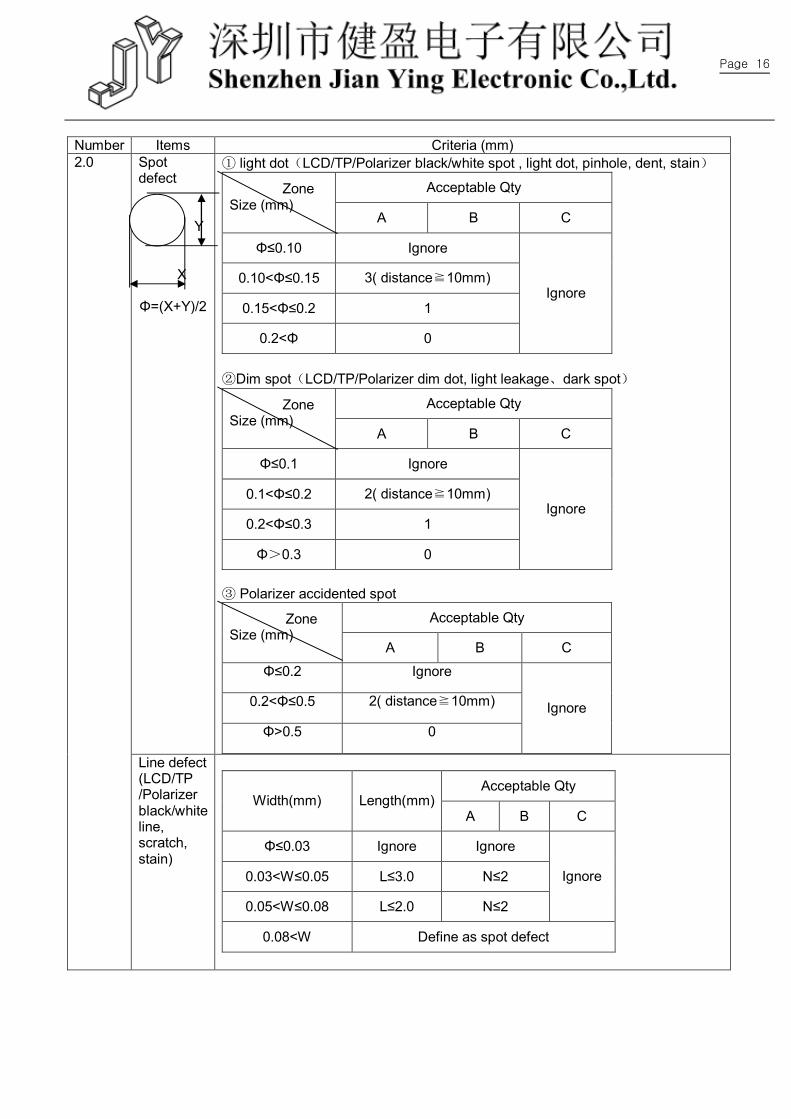
Number Items Criteria (mm)
Spot defect
Y X Φ=(X+Y)/2
① light dot(LCD/TP/Polarizer black/white spot , light dot, pinhole, dent, stain)
Acceptable Qty Zone Size (mm)
A B C
Φ≤0.10 Ignore
0.10<Φ≤0.15 3( distance≧10mm)
0.15<Φ≤0.2 1
0.2<Φ 0
Ignore
②Dim spot(LCD/TP/Polarizer dim dot, light leakage、dark spot)
Acceptable Qty Zone Size (mm)
A B C
Φ≤0.1 Ignore
0.1<Φ≤0.2 2( distance≧10mm)
0.2<Φ≤0.3 1
Φ>0.3 0
Ignore
③ Polarizer accidented spot
Acceptable Qty Zone Size (mm)
A B C
Φ≤0.2 Ignore
0.2<Φ≤0.5 2( distance≧10mm)
Φ>0.5 0
Ignore
2.0
Line defect (LCD/TP /Polarizer black/white line, scratch, stain)
Acceptable Qty
Width(mm) Length(mm) A B C
Φ≤0.03 Ignore Ignore
0.03<W≤0.05 L≤3.0 N≤2
0.05<W≤0.08 L≤2.0 N≤2
Ignore
0.08<W Define as spot defect
Page 17
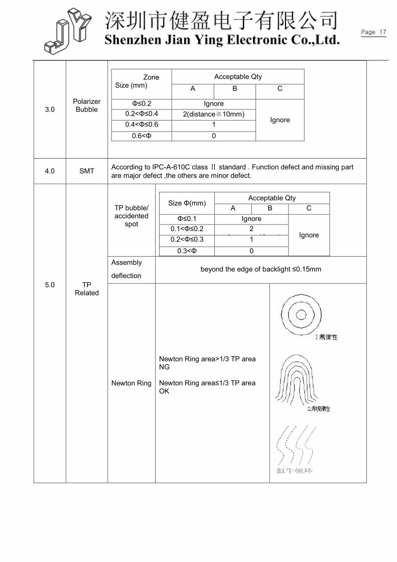
3.0 Polarizer Bubble
Acceptable Qty Zone
Size (mm) A B C
Φ≤0.2 Ignore 0.2<Φ≤0.4 2(distance≧10mm) 0.4<Φ≤0.6 1
0.6<Φ 0
Ignore
4.0 SMT According to IPC-A-610C class Ⅱ standard . Function defect and missing part are major defect ,the others are minor defect.
TP bubble/ accidented
spot
Acceptable Qty
Size Φ(mm) A B C
Φ≤0.1 Ignore 0.1<Φ≤0.2 2
(distance≧10mm) 0.2<Φ≤0.3 1 0.3<Φ 0
Ignore
Assembly
deflection beyond the edge of backlight ≤0.15mm
5.0
TP Related
Newton Ring
Newton Ring area>1/3 TP area NG
Newton Ring area≤1/3 TP area OK
Page 18
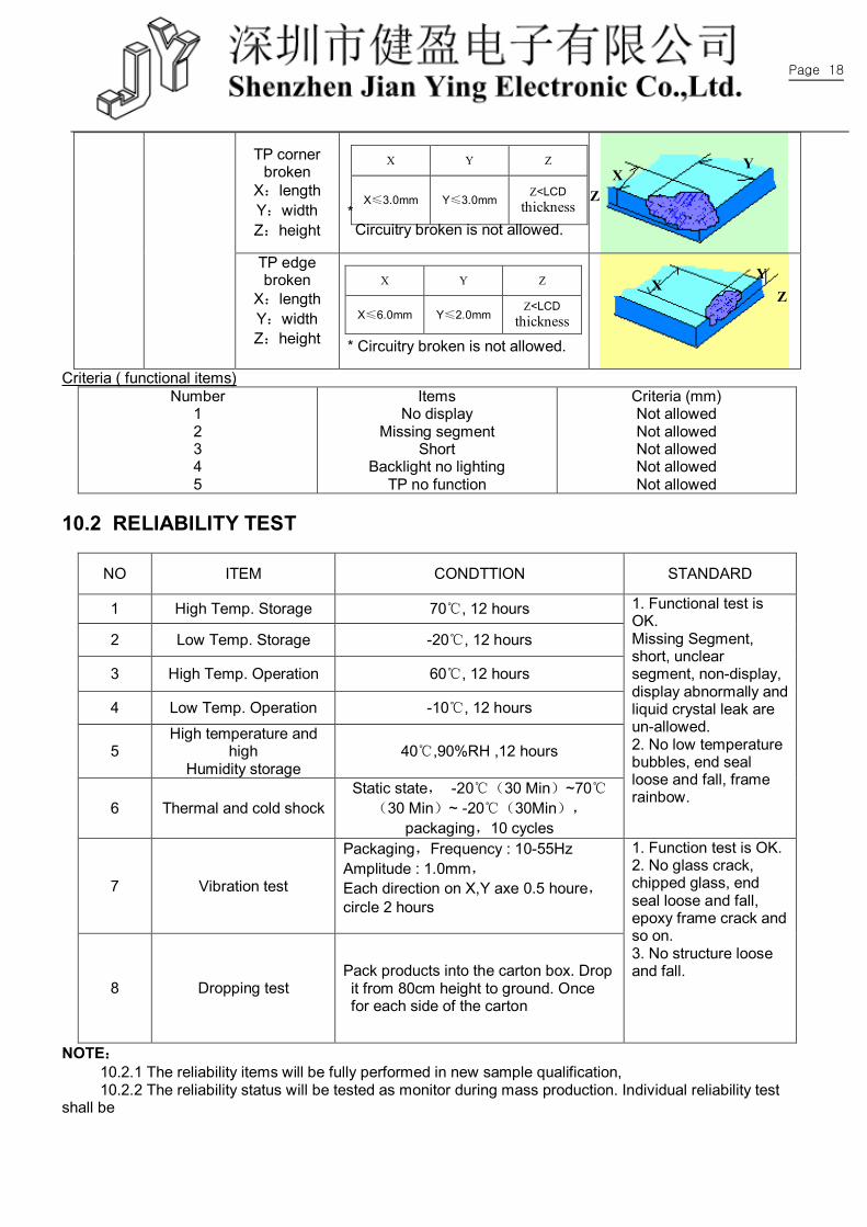
TP corner broken
X:length Y:width Z:height
* Circuitry broken is not allowed.
TP edge broken
X:length Y:width Z:height
* Circuitry broken is not allowed.
Criteria ( functional items)
Number 1 2 3 4 5
Items No display
Missing segment Short
Backlight no lighting TP no function
Criteria (mm) Not allowed Not allowed Not allowed Not allowed Not allowed
10.2 RELIABILITY TEST
NO ITEM CONDTTION STANDARD
1 High Temp. Storage 70℃, 12 hours
2 Low Temp. Storage -20℃, 12 hours
3 High Temp. Operation 60℃, 12 hours
4 Low Temp. Operation -10℃, 12 hours
5 High temperature and
high Humidity storage
40℃,90%RH ,12 hours
6 Thermal and cold shock Static state, -20℃(30 Min)~70℃
(30 Min)~ -20℃(30Min),
packaging,10 cycles
1. Functional test is OK. Missing Segment, short, unclear segment, non-display, display abnormally and liquid crystal leak are un-allowed. 2. No low temperature bubbles, end seal loose and fall, frame rainbow.
7 Vibration test
Packaging,Frequency : 10-55Hz Amplitude : 1.0mm, Each direction on X,Y axe 0.5 houre,circle 2 hours
8 Dropping test Pack products into the carton box. Drop it from 80cm height to ground. Once for each side of the carton
1. Function test is OK. 2. No glass crack, chipped glass, end seal loose and fall, epoxy frame crack and so on. 3. No structure loose and fall.
NOTE: 10.2.1 The reliability items will be fully performed in new sample qualification, 10.2.2 The reliability status will be tested as monitor during mass production. Individual reliability test
shall be
Z X
Y X Y Z
X≤3.0mm Y≤3.0mm Z<LCD
thickness
X Y Z
X≤6.0mm Y≤2.0mm Z<LCD
thickness
X Y
Z
Page 19
performed by lot , Moreover, the individual reliability item shall be decided according to reliability plan.
10.2.3 All samples are inspected after keeping in the room with normal temperature and humidity for 2 hours or above.
10.2.4 Vibration test: It is not necessary to test for those products without assembly frame , back light ,PCB and so on.
10.2.5 Dropping test : It is necessary for affirming new package. 10.2.6 For the high temperature and high humidity test, pure water of over 10 MΩ.cm should be used. 10.2.7 Each test item applies for test LCM only once .Then tested LCM cannot be used again in any
other test item. 10.2.8 The quantity of LCM examination for each test item is 5pcs to 10pcs.
10.3 Safetv instructions
10.3.1 If the LCD panel breaks, be careful not to get any liquid crystal substance in your mouth. 10.3.2 If the liquid crystal substance touches your skin or clothes, please wash it off immediately by using
soap and water. 10.4 Handling Precautions
10.4.1 Avoid static electricity damaging the LSI. 10.4.2 Do not remove the panel or frame from the module . 10.4.3 The polarizing plate of the display is very fragile . So, please handle it very carefully. 10.4.4 Do not wipe the polarizing plate with a dry cloth, as it may easily scratch the surface of the plate. 10.4.5 The color tone of display and background of LCM has the possibility to be changed in the storage
temperature range. 10.4.6 Pay attention to the working environment, as the element may be destroyed by static electricity.
--Be sure to ground human body and electric appliance during work. --Avoid working in a dry environment to minimize the generations of static electricity. --Static electricity may be generated when the protective film is fast peeled off.
10.4.7 When soldering the terminal of LCM, make certain the AC power source of soldering iron does not leak. 10.4.8 If the display surface becomes contaminated ,breathe on the surface and gently wipe it with a soft-
dry- clean cloth .If it is heavily contaminated ,moisten cloth with the following solvent(ex:Ethyl alcohol).Solvents other than those above-mentioned may damage the polarizer(Especially ,do not use them .ex: Warter / Ketone)
10.5 Operation instructions
10.5.1 It is recommended to drive the LCD within the specified voltage limits, try to adjust the operating voltage for the optimal contrast, the color and contrast of LCD panel will varies at different temperature.
10.5.2 Response time is greatly delayed at low operating temperature range. However, this does not mean the LCD will be out of the order, It will recover when it returns to the specified temperature range.
10.5.3 If the display area is pushed hard during operation, the display will become abnormal. 10.5.4 Do not operate the LCD at the environments over the specified conditions, this may cause damage
on the LCD and shorten the lifetime. 10.6 Storage instructions:
10.6.1 Store LCDs in a sealed polyethylene bag. 10.6.2 Store LCDs in a dark place, Do not expose to sunlight or fluorescent light. Keep the temperature
between 0℃and 35℃. 10.6.3 Avoid the polarizer touch any other object, ( It is recommended to store them in the container in
which they were shipped.) 10.7 Limited Warranty
Page 20
10.7.1 will replace or repair any of its LCD modules, which are found to be defective, when inspected in accordance with LCM acceptance standards ( copies available upon request ) for a period of 12 months from ink- print date on product
10.7.2 Any defects must be returned to within 60 days since ship-out. Confirmation of such date shall be based on freight documents. The warranty liability of wasam limited to repair and/or replacement on defects above (7.1,7.2)
10.7.3 No warranty can be granted if the precautions stated above have been disregarded. The typical samples are as below: -- LCD glass crack/break --PCB outlet is damaged or modified. --PCB conductors damaged. --Circuit modified with by grinding, engraving or painting varnish. --FPC crack
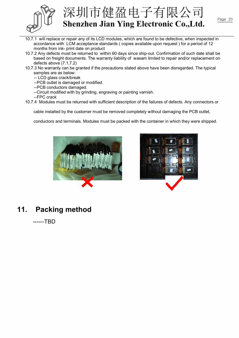
10.7.4 Modules must be returned with sufficient description of the failures of defects. Any connectors or
cable installed by the customer must be removed completely without damaging the PCB outlet,
conductors and terminals. Modules must be packed with the container in which they were shipped.
11. Packing method
------TBD