Embed Size (px)
Citation preview
Engineering Specification Signals Construction
Engi
neer
ing
Spec
ifica
tion
SPG 0714
COMPRESSED AIR SYSTEMS
Version 3.0
Issued March 2013
Owner: Chief Engineer Signals and Control Systems
Approved by: Warwick Allison Chief Engineer Signals and Control Systems
Authorised by:
David Nolan Principal Engineer Signal Equipment and Interfaces
Disclaimer This document was prepared for use on the RailCorp Network only. RailCorp makes no warranties, express or implied, that compliance with the contents of this document shall be sufficient to ensure safe systems or work or operation. It is the document user’s sole responsibility to ensure that the copy of the document it is viewing is the current version of the document as in use by RailCorp. RailCorp accepts no liability whatsoever in relation to the use of this document by any party, and RailCorp excludes any liability which arises in any manner by the use of this document. Copyright The information in this document is protected by Copyright and no part of this document may be reproduced, altered, stored or transmitted by any person without the prior consent of RailCorp.
UNCONTROLLED WHEN PRINTED Page 1 of 39
RailCorp Engineering Specification — Signals — Construction Compressed Air Systems SPG 0714
© RailCorp Page 2 of 39 Issued March 2013 UNCONTROLLED WHEN PRINTED Version 3.0
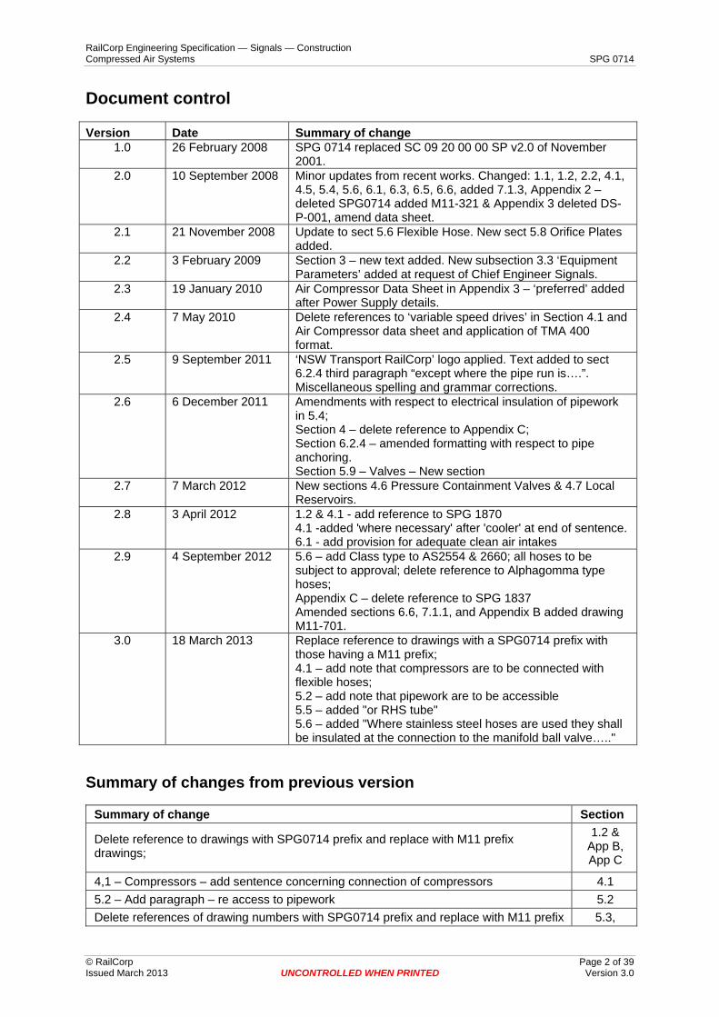
Document control
Version Date Summary of change 1.0 26 February 2008 SPG 0714 replaced SC 09 20 00 00 SP v2.0 of November
2001. 2.0 10 September 2008 Minor updates from recent works. Changed: 1.1, 1.2, 2.2, 4.1,
4.5, 5.4, 5.6, 6.1, 6.3, 6.5, 6.6, added 7.1.3, Appendix 2 – deleted SPG0714 added M11-321 & Appendix 3 deleted DS-P-001, amend data sheet.
2.1 21 November 2008 Update to sect 5.6 Flexible Hose. New sect 5.8 Orifice Plates added.
2.2 3 February 2009 Section 3 – new text added. New subsection 3.3 ‘Equipment Parameters’ added at request of Chief Engineer Signals.
2.3 19 January 2010 Air Compressor Data Sheet in Appendix 3 – ‘preferred’ added after Power Supply details.
2.4 7 May 2010 Delete references to ‘variable speed drives’ in Section 4.1 and Air Compressor data sheet and application of TMA 400 format.
2.5 9 September 2011 ‘NSW Transport RailCorp’ logo applied. Text added to sect 6.2.4 third paragraph “except where the pipe run is….”. Miscellaneous spelling and grammar corrections.
2.6 6 December 2011 Amendments with respect to electrical insulation of pipework in 5.4; Section 4 – delete reference to Appendix C; Section 6.2.4 – amended formatting with respect to pipe anchoring. Section 5.9 – Valves – New section
2.7 7 March 2012 New sections 4.6 Pressure Containment Valves & 4.7 Local Reservoirs.
2.8 3 April 2012 1.2 & 4.1 - add reference to SPG 1870 4.1 -added 'where necessary' after 'cooler' at end of sentence.6.1 - add provision for adequate clean air intakes
2.9 4 September 2012 5.6 – add Class type to AS2554 & 2660; all hoses to be subject to approval; delete reference to Alphagomma type hoses; Appendix C – delete reference to SPG 1837 Amended sections 6.6, 7.1.1, and Appendix B added drawing M11-701.
3.0 18 March 2013 Replace reference to drawings with a SPG0714 prefix with those having a M11 prefix; 4.1 – add note that compressors are to be connected with flexible hoses; 5.2 – add note that pipework are to be accessible 5.5 – added "or RHS tube" 5.6 – added "Where stainless steel hoses are used they shall be insulated at the connection to the manifold ball valve….."
Summary of changes from previous version
Summary of change Section
Delete reference to drawings with SPG0714 prefix and replace with M11 prefix drawings;
1.2 & App B, App C
4,1 – Compressors – add sentence concerning connection of compressors 4.1 5.2 – Add paragraph – re access to pipework 5.2 Delete references of drawing numbers with SPG0714 prefix and replace with M11 prefix 5.3,
RailCorp Engineering Specification — Signals — Construction Compressed Air Systems SPG 0714
© RailCorp Page 3 of 39 Issued March 2013 UNCONTROLLED WHEN PRINTED Version 3.0
drawings 6.2.4 5.5 – Add text. 5.5 5.6 – Add paragraph. 5.6 Drawings M11-349-1 and M11-349-2 updated to revision 'B' App B
RailCorp Engineering Specification — Signals — Construction Compressed Air Systems SPG 0714
© RailCorp Page 4 of 39 Issued March 2013 UNCONTROLLED WHEN PRINTED Version 3.0
Contents
1 Scope........................................................................................................................................6 1.1 Introduction ...............................................................................................................................6 1.2 Reference Documents, Standards and Codes .........................................................................6 1.3 Installer Supplied Data ..............................................................................................................7 2 Design ......................................................................................................................................7 2.1 Design Inputs ............................................................................................................................7 2.2 Design Documentation..............................................................................................................8 3 Fluid Parameters, Site Details and Equipment Parameters................................................8 3.1 Fluid Parameters.......................................................................................................................8 3.2 Environmental and Site Factors................................................................................................8 3.3 Equipment Parameters .............................................................................................................8
3.3.1 Points .........................................................................................................................8 3.3.2 Train Stops ................................................................................................................9
4 Equipment Supply...................................................................................................................9 4.1 Compressors.............................................................................................................................9 4.2 Receivers ..................................................................................................................................9 4.3 Dryers........................................................................................................................................9 4.4 Expansion Joints .......................................................................................................................9 4.5 Miscellaneous Equipment .........................................................................................................9 4.6 Pressure Containment Valves ..................................................................................................9 4.7 Local Reservoirs .....................................................................................................................10 5 Pipework ................................................................................................................................10 5.1 Piping Classes ........................................................................................................................10 5.2 Pipework Arrangement............................................................................................................10 5.3 Steel Piping .............................................................................................................................11 5.4 Insulation Joints ......................................................................................................................11 5.5 Manifolds.................................................................................................................................12 5.6 Flexible Hose ..........................................................................................................................12 5.7 Identification and Painting.......................................................................................................13 5.8 Orifice Plates...........................................................................................................................14 5.9 Valves......................................................................................................................................14 6 Installation .............................................................................................................................14 6.1 Equipment / Compressor Room..............................................................................................14 6.2 Pipework Installation ...............................................................................................................15
6.2.1 General ....................................................................................................................15 6.2.2 Access .....................................................................................................................15 6.2.3 Storage ....................................................................................................................16 6.2.4 Supports ..................................................................................................................16
6.3 Cleaning ..................................................................................................................................17 6.4 Safety Equipment....................................................................................................................17 6.5 Drainage & Ventilation ............................................................................................................17 6.6 Control & Maintainers System ................................................................................................17 7 Testing and Commissioning................................................................................................18

RailCorp Engineering Specification — Signals — Construction Compressed Air Systems SPG 0714
© RailCorp Page 5 of 39 Issued March 2013 UNCONTROLLED WHEN PRINTED Version 3.0
7.1 Testing.....................................................................................................................................18 7.1.1 Mechanical Equipment Testing ...............................................................................18 7.1.2 Pipework Testing .....................................................................................................18 7.1.3 System Testing ........................................................................................................19
7.2 Precommissioning...................................................................................................................19 7.3 Commissioning........................................................................................................................19 Appendix A Typical System Documentation ...........................................................................21 Appendix B Drawings.................................................................................................................23 Appendix C Data Sheets ............................................................................................................36
RailCorp Engineering Specification — Signals — Construction Compressed Air Systems SPG 0714
© RailCorp Page 6 of 39 Issued March 2013 UNCONTROLLED WHEN PRINTED Version 3.0
1 Scope
1.1 Introduction This specification details the design, fabrication, installation, testing and commissioning of compressed air systems for railway signalling use, and is to be used for both new and altered systems. The compressed air system includes, but is not limited to, air Compressor Rooms (consisting of air compressors, dryers, and controls), air receivers, pipe-work and associated piping components such as manifolds and valves. The compressed air systems will be used to operate track turnouts (points) and train stops, both of which are actuated by pneumatic cylinders.
1.2 Reference Documents, Standards and Codes The following reference documents form part of this specification.
M11-349-1 & 2 Standard Air System Drawing Symbols for Air Systems M11-351-1 & 2 Compressed Air Piping Arrangement M11-350 Connection Single Trainstop to Main M11-352 Anchor Points M11-353 Steel Air Main Bracket M11-355 Label Holder Installation, Part: Carrington Tang Clamp, 1/2” and ¾” M11-354 Label Holder Installation Example on General Manifold Arrangement SPG 1870 Air Compressors for Signalling Systems
M11-307 Air Hose, P.V.C. detail of Fittings Drawings produced from design phase DS-P-001 GMS01 Piping DS-P-002 MS01 Piping DS-P-003 SS01 Piping DS-P-004 Halogen Free Flexible Piping DS-EQ-001 Air Compressor DS-EQ-002 Compressed Air Dryer DS-EQ-003 Air Receiver SPG 0705 Construction of Cable Route and Associated Civil works ESG 100.25 Compressed Air Systems SPG 0703 Signalling Documentation and Drawings The following Australian Standards and statutory codes form part of this specification.
AS 1074 Steel Tubes and Tubulars for Ordinary Service AS 1210 Pressure Vessels AS 1345 Identification of the Contents of Piping, Conduits and Ducts AS/NZS 1477 PVC Pipes and Fittings For Pressure Applications AS/NZS 1518 External Extruded High-density Polyethylene Coating System for Pipes AS 2129 Flanges for Pipes, Valves and Fittings AS/NZS 2554 Hose and Hose Assemblies for Air AS 2660 Hose and Hose Assemblies – Air/water – For Underground Coal Mines AS 4041 Pressure Piping AS/NZS 4680 Hot-dip Galvanized (Zinc) Coatings on Fabricated Ferrous Articles
RailCorp Engineering Specification — Signals — Construction Compressed Air Systems SPG 0714
© RailCorp Page 7 of 39 Issued March 2013 UNCONTROLLED WHEN PRINTED Version 3.0
AS/NZS 4792 Hot-dip Galvanized (Zinc) Coatings on Ferrous Hollow Sections, Applied by a Continuous or a Specialized Process NSW Work, Health and Safety Act 2010. NSW Work, Health and Safety Regulations 2011 Rail Safety Act 2002
1.3 Installer Supplied Data Refer to Appendix A for Installer supplied data.
2 Design
2.1 Design Inputs The following data shall form part of the design inputs, along with other data listed in the Particular Specification (eg scope of work) and RailCorp Design Principles document:
Reference documents, standards and codes (refer Section 1.2);
Available information on the existing air reticulation system and pneumatic signalling equipment in the project area to which the new work is to be connected; and/or plans showing the proposed location of the new pneumatic signalling equipment;
Available information on the location of existing cable routes and any existing air reticulation system which is to be replaced by the new work;
Available information on the current noise, air and waste emission approval limits, including any information on any new limits which may apply to the works;
Fluid parameters (refer Section 3.1);
Environmental and site factors (refer Section 3.2);
Operating and control philosophy (refer to document ESG 100.25);
Design life of 25 years for equipment, and 50 years for pipework and structures;
Maximum thermal expansion of -10 °C to 60 °C, and maximum thermal movement of a manifold or cross tie branch to be +/- 25 mm;
The equipment and pipe work shall be designed and installed to provide maximum protection and safety for operating and maintenance personnel. Safety equipment shall include guards, access covers, inspection covers, emergency stop equipment, safety interlocks, and other devices required by the statutory authorities;
The pipework shall be designed to ensure all manually operated valves are in positions where the valve hand wheel can be comfortably reached and operated from an access platform, floor, walkway or stairway; and
Permanent lifting devices to be provided for operation and maintenance personnel, such that maximum manual lift weight is 16 kg. This limit may be lowered further in specific instances, based on the outcomes of a risk assessment (refer WH&S Act 2010).
All equipment proposed for the air system shall require type approval.
RailCorp Engineering Specification — Signals — Construction Compressed Air Systems SPG 0714
© RailCorp Page 8 of 39 Issued March 2013 UNCONTROLLED WHEN PRINTED Version 3.0
2.2 Design Documentation The following design documentation shall be generated, as a minimum, during the design process:
Process flow diagram, mass balance, and/or network hydraulic model, to document the capacity of the extended/new system;
Equipment, piping and instrument data sheets in sufficient detail to allow procurement of these items;
General arrangement, layout and detail drawings of the Compressor Room equipment and instrument installation;
Electrical power and control details, including protection scheme and interface list;
Schematic books, similar to current books, detailing the new pipework involved, connections to existing pipework, and corrections to existing schematics;
Specifications to cover fabrication, installation, and commissioning requirements; and
Functional description in sufficient detail to allow software coding to proceed.
Maintain VDU + Compressor PLC system design user manual, including all software & licences.
3 Fluid Parameters, Site Details and Equipment Parameters
3.1 Fluid Parameters Fluid parameters are:
Fluid is compressed air to quality class 2.4.2 of ISO 8573, downstream of dryer post-filter;
Temperature range 10ºC to 50ºC between compressors and receivers; and
Temperature range -10ºC to + 60ºC downstream of receiver.
3.2 Environmental and Site Factors Environmental and site factors are:
• Location is the Railcorp region within NSW; • Ambient temperature range –10 to +60ºC; • Rainfall range 600 mm to 2000 mm per annum; • Humidity range 40% RH to 100% RH; • Ground conditions may include induced currents from rail power supply; • Potential close proximity to noise sensitive areas; and • Other environmental factors are vibration (from rail traffic) and mechanical damage
(impacts from ballast during rail maintenance).
3.3 Equipment Parameters
3.3.1 Points An EP points motor with 125 mm bore and 180 mm stroke has a volumetric capacity of 0.0022 cu M.
RailCorp Engineering Specification — Signals — Construction Compressed Air Systems SPG 0714
© RailCorp Page 9 of 39 Issued March 2013 UNCONTROLLED WHEN PRINTED Version 3.0
3.3.2 Train Stops An electro-pneumatic trainstop having cylinder dimensions of 76 mm bore & 70 mm stroke has a volumetric capacity of 0.0003175 cu M.
4 Equipment Supply
4.1 Compressors Compressors shall be in accordance with SPG 1870 complete with integral oil separator and after cooler where necessary. The minimum size shall be 10 Litres/Second capacity. Units shall be delivered, handled and stored in a manner which maintains the “new” condition of the units.
Compressors shall be connected to the fixed pipework by flexible stainless steel hoses.
4.2 Receivers Receivers shall be horizontal or vertical cylindrical pressure vessels of carbon steel welded construction in accordance with AS 1210. Integration of the receiver into the compressor skid should be considered for smaller systems. Units shall be delivered, handled and stored in a manner which maintains the “new” condition of the units.
4.3 Dryers Dryers shall be refrigerated type units. Units shall be delivered, handled and stored in a manner which maintains the “new” condition of the units.
4.4 Expansion Joints Expansion joints shall be externally pressurised bellows type units, complete with drain port. Bellows shall be stainless steel, and other components shall be carbon steel. Flanges shall be AS 2129 Table E. Joints shall be designed and manufactured in accordance with Expansion Joint Manufacturers Association recommendations. An anchor point is to be provided mid point between expansion joints.
4.5 Miscellaneous Equipment Miscellaneous equipment will be as follows:
All air filters shall be fitted with differential pressure (dp) valves;
Lifting devices for compressors shall be monorails or gantry cranes, complete with wire rope hoist, electric raise/lower, electric travel and pendant control;
4.6 Pressure Containment Valves Each trainstop and manifold shall be fed through a non-return valve located after the main shut off valve. This valve is to prevent loss of air from the equipment in the event of an air main failure.
The pressure containment valve shall be of stainless steel construction with either metal-metal or metal/Teflon seats.
These valves shall be maintenance-free.
RailCorp Engineering Specification — Signals — Construction Compressed Air Systems SPG 0714
© RailCorp Page 10 of 39 Issued March 2013 UNCONTROLLED WHEN PRINTED Version 3.0
4.7 Local Reservoirs Local reservoirs shall be provided when required to even out airflow demand and to backup the air supply pressure where a number of equipment items are fed from the one manifold.
The local reservoir shall be of stainless steel construction with the air connection at the low point, small diameter and vertically mounted. They may require Workcover design registration, but not require any other ongoing registration or maintenance other than inspection. The units shall not exceed a PV of 100 MPaL, based on a design pressure of 720 kpa (approximately 135 L capacity maximum – Hazard Level D to AS4343).
If the design requires, more than one unit may be installed to provide a greater capacity. Usually they shall be installed at manifolds.
A point orifice plate shall be fitted at the manifold if connected via a PVC hose.
5 Pipework
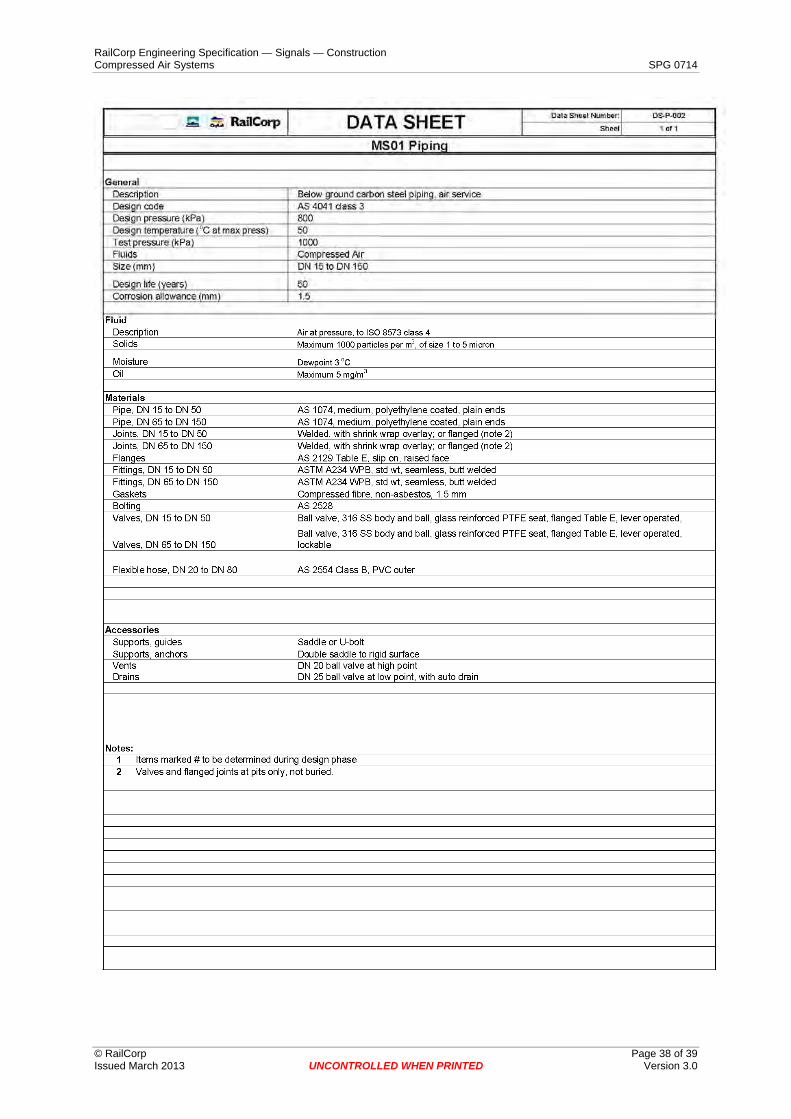
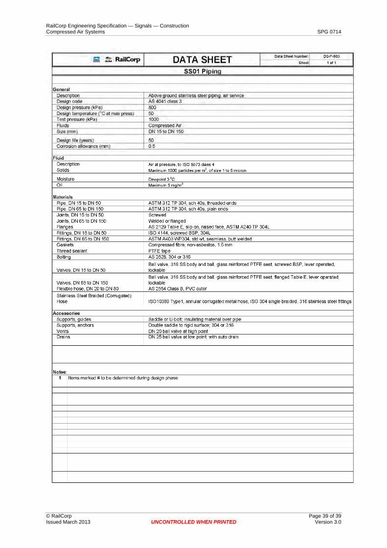
5.1 Piping Classes Piping classes are listed in the piping data sheets (refer Appendix C), and contain details of design pressures, temperatures, materials etc. All pipework shall be selected from these piping classes only, and shall comply with AS 4041.
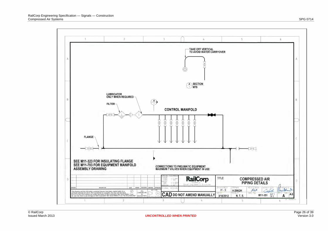
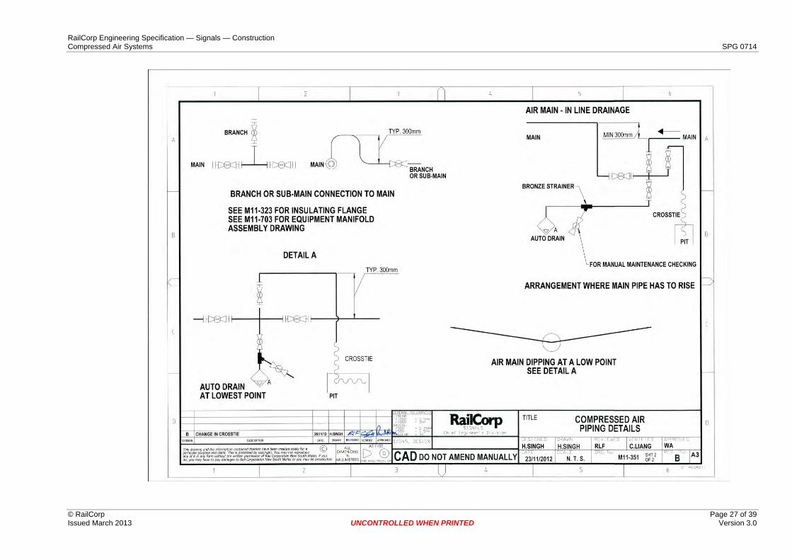
5.2 Pipework Arrangement Pipework design principles are shown in the reference drawings (refer Appendix B). These demonstrate preferred methods for manifolds, branches, drains, etc and shall be adhered to in the design of the new work.
Underground cross ties shall be flexible hose within PVC pressure pipe conduit or galvanised steel pipe with 450g/m2 coating. No joints shall be allowed in flexible hose.
A cross tie using flexible hose may be installed in a single conduit with up to two large radius bends at each end to avoid the need for a pit.
Pipework shall be designed to ensure that there is sufficient flexibility to absorb any expansion or contraction, without excessive stresses or loads on equipment, or cause leakage at joints. Expansion joints, expansion loops, anchor points, pipe bends and other items as necessary shall be considered for this purpose.
Compressed air lines shall slope downward in direction of flow, at 1:200. Condensate trap points shall be placed at the bottom of vertical risers. Inline drainage trap points for compressed air shall consist of a tee, drop leg, ball valve and auto drain. Waste water lines shall slope downward in direction of flow, at 1:40. Notwithstanding this valves and equipment shall not be located in pits. Valving arrangements shall facilitate the blowing out of water that may accumulate in low sections.
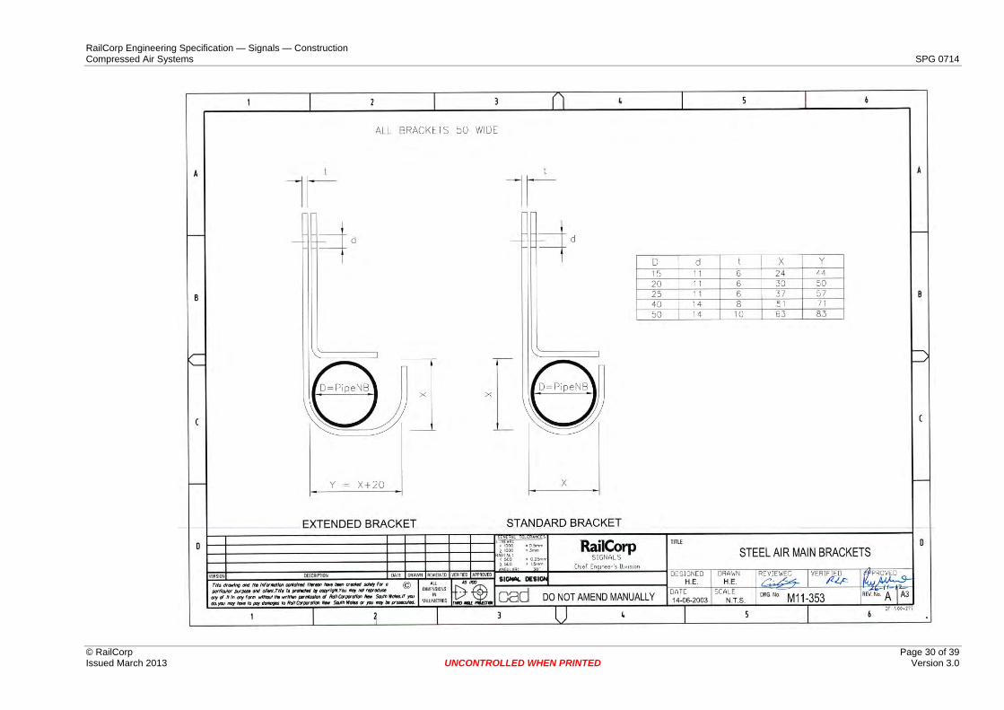
Except at anchor points, the brackets supporting the main shall allow axial freedom for expansion and contraction but shall not permit vertical or lateral movement exceeding 5mm (2mm either side of expansion joints).
The bracket shall be manufactured from hot dip galvanised steel except in tunnels where it shall be manufactured from stainless steel.
RailCorp Engineering Specification — Signals — Construction Compressed Air Systems SPG 0714
© RailCorp Page 11 of 39 Issued March 2013 UNCONTROLLED WHEN PRINTED Version 3.0
All pipework shall be easily accessible. Where pipe connections are unavoidably elevated, a union shall be provided at an accessible position to permit work on the piping without the necessity to access the elevated portions.
5.3 Steel Piping The compressed air lines shall generally be constructed from galvanised carbon steel pipe, or stainless steel pipe.
For carbon steel lines, joints shall generally be screwed or flanged, as required. Welding procedures to be used by the Installer shall be submitted for approval before commencing work. These shall include weld repair procedures. Welded pipe spools are to be hot dipped galvanised after fabrication.
For stainless steel lines, joints shall generally be screwed, welded or flanged. Weld filler metal shall have corrosion resistant properties similar to or better than the base metal. The welding procedure followed shall preserve corrosion resistance in the weld and heat affected zone to maintain optimum mechanical properties in the joint and minimise heat distortion. Fabrication shall be carried out with equipment made from stainless steel, free from contaminants and which has not previously been used on carbon steel or non ferrous material. Joint cleaning shall not use chlorinated solvent.
All joints shall be aligned with mechanical devices and shall be free of depressions and bumps. Heat shall not be used to obtain alignment.
Steel air mains must never be attached to overhead wiring structures or signal gantries (Except for cross ties addressed in Section 5.4). A minimum clearance of 75mm must be maintained between the air line and overhead wiring structure or signal gantry.
Wherever practical steel air main should be placed two metres from any overhead wiring structure or signal gantry.
5.4 Insulation Joints Insulation joints shall be rated for 2500V AC for one second.
Insulation joints shall be installed in the following locations:
• Between the main and the Compressor Room; • Where the main enters or leaves the ground or a pit; • Within 1 m of each end of any steel bridge; • Every 500 m in the steel mains; and • Coincident with steel troughing insulated joints, where both pipe and troughing
utilise the same support.
At least two insulated joints shall be provided between any two signalling locations.
Where the air line is within 2 m of an overhead wiring structure that is not fitted with a spark gap, the line is to be covered with an insulating sleeve (eg class 12 PVC pipe) for a distance of 2 m either side of the structure. Suitable clamps or clips are to be provided to prevent movement.
Where steel pipe is used for an overhead cross tie, it must be separated from the steel main by at least 2.0 metres of flexible PVC air hose.
Insulated joints shall not be located where they could be bypassed by a metal structure (e.g. a metal bridge).
RailCorp Engineering Specification — Signals — Construction Compressed Air Systems SPG 0714
© RailCorp Page 12 of 39 Issued March 2013 UNCONTROLLED WHEN PRINTED Version 3.0
5.5 Manifolds Manifolds shall be constructed from stainless steel pipe or stainless steel RHS tube, and comply with the requirements of the drawings listed in Appendix B.
Manifolds shall be placed adjacent to the equipment to which they are to be connected. Where it is physically impossible to place a manifold within 75 metres from the equipment it supplies the installer must seek additional approval.
Take offs from the main air lines shall preferably be vertically upwards. Where the manifolds are to be located below the main air line a low point & drain shall be provided below the take off points.
5.6 Flexible Hose All polymeric hoses not in tunnels shall be fabricated in accordance with AS/NZS 2554 Class B. All polymeric hoses in tunnels shall generally be in accordance with AS 2660 Class A, and must be ‘low smoke halogen free’ as required by cable specification RHG-3 of AS 4507. All hoses are to be subject to approval. Stainless steel hoses shall be fabricated in accordance with relevant ISO standards, and to be an approved type.
Flexible hose shall always be used for the connection between manifold and pneumatic equipment. All flexible air hoses shall be protected from sunlight by conduit. Hose connections to equipment within five metres of a manifold shall be run on the surface within a flexible orange coloured PVC conduit. If the equipment is more than five metres from the manifold, the hose and conduit shall be buried as per SPG 0705 “Construction of Cable Route and Associated Civil Works”. The flexible conduit is to be carried to within 100mm of the connection at each end of the hose whether buried or surface run.
Where stainless steel hoses are used, they shall be insulated at the connection to the manifold ball valve. Stainless steel hoses that run beneath the rails shall be enclosed in flexible orange coloured PVC conduit.
Where flexible air hose is used for the main air line, it shall be installed in a properly constructed cable route in accordance with SPG 0705.
Tails for flexible hoses shall be:
• For hoses less then 18 mm Nominal Bore (NB) a single non-serrated bulb tail with one single stainless steel Bandit Clamp or approved equivalent.
• For hoses 18 mm NB or greater a double non-serrated bulb tail with two stainless steel Bandit Clamp or approved equivalent.
Tails shall be of a type that does not damage the hose. Tail size shall be specifically assessed as the correct size for the hose type. Specifically the end of the tail shall be smooth and rounded to prevent damage to the pipe when flexed.
Bandit type clamps or approved equivalent shall only be applied using an approved tool which applies a pre set consistent application pressure. Clamps shall apply an even pressure around the entire circumference of the hose.
The female union nut shall be capable of rotating without twisting the hose.
Where a main flexible air hose is to be bent through a radius less than the manufacturers recommended minimum radius, a stainless steel elbow shall be installed.
Flexible hoses shall not be bent within a distance of (5 x Hose Outside Diameter) to the tail. Additional hose supports / clamps shall be provided where necessary to achieve this.
Flexible air hoses shall be buried in a separate conduit, in buried cable routes.
RailCorp Engineering Specification — Signals — Construction Compressed Air Systems SPG 0714
© RailCorp Page 13 of 39 Issued March 2013 UNCONTROLLED WHEN PRINTED Version 3.0
In GST and GLT installations the air hose must be laid on top of all cables to avoid compression of the air line.
The ends of all flexible air hoses shall be sealed during installation to prevent the ingress of dirt or water.
5.7 Identification and Painting Individual pipework items such as valves, manifolds, instruments, and expansion joints shall be fitted with permanent labels. The label shall be made of stainless steel, and fixed to the equipment using split rings or screws. Characters shall be a minimum of 4 mm high. Identification label inscriptions shall include the following information:
Valve/manifold/instrument/joint code (up to 8 characters);
Manufacturer's model number and size; and
Design rating.
Valve codes shall be as follows:
Air user control valves – ‘SY 456S TS’, ‘333 PTS’;
Stop valves on mains, cross ties, manifolds etc – ‘N.O.’ or ‘N.C.’;
Stop valves on sub-main feeds – ‘Sub-main 111 PTS, 113 PTS, 444 TS’; and
Stop valves on outlet of receivers/compressors feeding certain areas – ‘Down Main West’;
Manifold codes shall be determined during the design phase, in consultation with the Asset Owner and Asset Maintainer.
All pipeline contents shall be identified by self adhesive labels, in accordance with the methods given in AS 1345. The direction of flow shall be suitably indicated at each label. When the pipe size is very small, the strip is to be affixed by a suitable flag off the pipe in accordance with the standard. The following method of colour coding is to be used:
An identifying strip is to be fixed to the pipe at the intervals recommended by the standard. The identifying strip is to have coloured lettering on a white background. The coloured lettering is to be in accordance with the pipeline colour as shown in Table 1 below;
The arrow indicating the direction of flow shall be the same colour as the lettering on the identifying strip; and
Where necessary, warning flags are to be located at the ends of the identifying strip in accordance with the standard.
Pipe Contents Colour (to AS 2700 u.n.o.) Compressed Air B25 Aqua Waste Water Black
Table 1 - Pipe Colours
Letters shall be as follows:
• 25 mm Letters up to DN 80
RailCorp Engineering Specification — Signals — Construction Compressed Air Systems SPG 0714
© RailCorp Page 14 of 39 Issued March 2013 UNCONTROLLED WHEN PRINTED Version 3.0
• 50 mm Letters above DN 80
The location of identification labels shall be at intervals of not more than 8 m, adjacent to changes in direction, branches, junctions, valves, wall penetrations and control points. Labels shall be placed so that they are easily seen. Uninterrupted lengths of external services, visible along their length, shall have labels at 50 m maximum intervals.
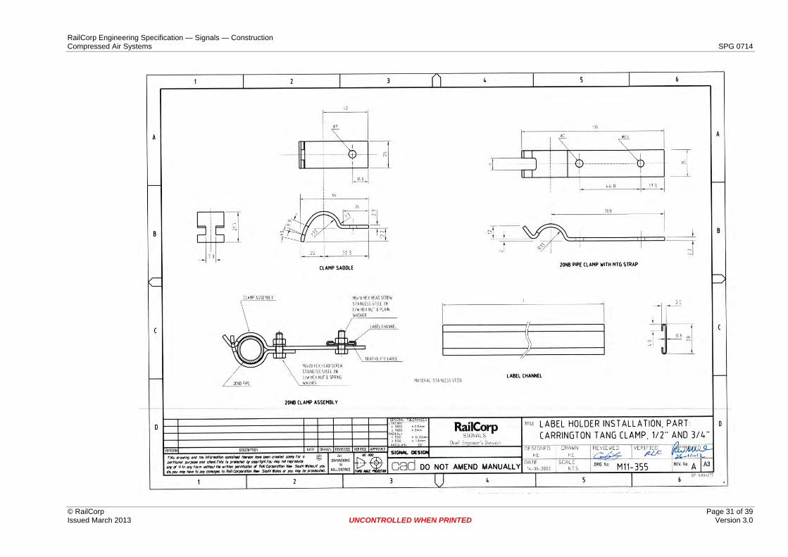
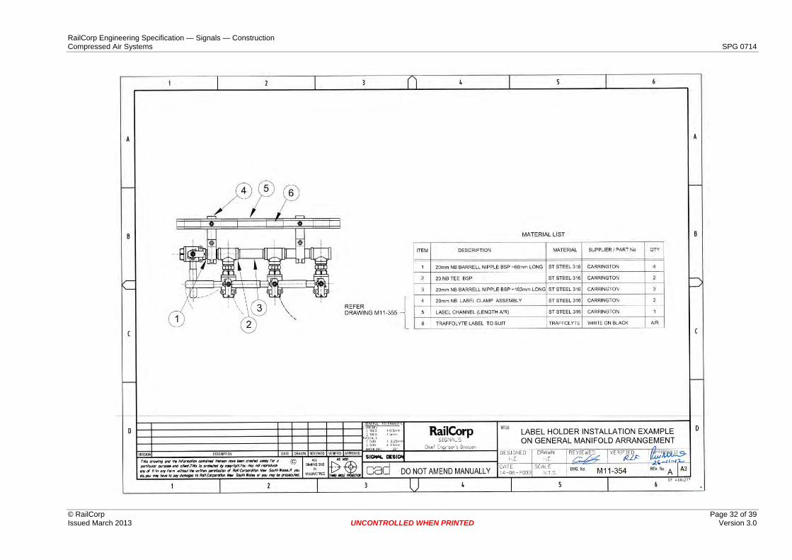
Manifold label holders shall be constructed from stainless steel, and incorporate traffolyte labels for manifold, valves, etc. The label holder installation shall be as shown in attached drawings M11-355 and M11-354.
Protective coatings are required for all ferrous pipework, pipe supports, and miscellaneous items. Equipment (compressors, dryers, receivers) will be supplied painted, in accordance with the manufacturers recommendations. Protective coatings shall be hot dipped galvanising to AS/NZS 4680 with 450g/m2 coating, unless noted otherwise. Damaged sections of galvanising shall be repaired in accordance with Galvanizers Association recommendations.
5.8 Orifice Plates Orifice plates shall be of nylon not less than 3.0 mm thick and shall be provided to protect against failure of flexible hoses.
Orifice sizes shall be:
• 1.6 mm for trainstops • 3.2 mm for points
Unless approved otherwise and shall be installed at manifolds. Orifice plates sizes in flexible mains hoses shall be determined in the design.
Orifice plates shall be securely installed between the flat faces of the nipples where inserted into the ball valves.
5.9 Valves Valves shall be full bore stainless steel, Teflon seat ball valve type to AS4796 with the following characteristics:
• Full bore ball valve. • Two piece body construction (small valves threaded together and larger valves
greater than 50mm bolted together) which allows for the replacement of seals. • Body made from stainless steel Grade 304 (needs to be Grade 316 in areas where
high levels of chlorine are present) • Female threaded connections to AS1722.1 (British Standard Whitworth parallel
form). • 90 degree operation between open and closed positions. • Whilst handle is attached, it can be locked in open or closed position.
6 Installation
6.1 Equipment / Compressor Room Equipment shall be installed on foundations or support structures. The Installer is responsible for supply of all materials needed (such as hold down bolts, grout, lubricants, etc) to complete the installation. The Installer shall follow all manufacturers’ instructions
RailCorp Engineering Specification — Signals — Construction Compressed Air Systems SPG 0714
© RailCorp Page 15 of 39 Issued March 2013 UNCONTROLLED WHEN PRINTED Version 3.0
for the installation of the equipment and shall recheck all drive alignments prior to testing of the equipment. The Installer shall check the dimensions on site of all interface points.
Where required, the Installer is to assemble equipment on site, in accordance with the manufacturers’ instructions.
Compressors shall be installed in their own room, with sufficiently large entrances to permit the equipment to be removed & maintained.
Adequate provision shall be provided for the supply of clean dry air for the compressor intakes in the quantity required to deliver the compressor outputs at their maximum demand.
In particular, humid moist areas shall not be used for drawing air.
Ventilation shall consider noise levels and be arranged so that the building itself reduces any noise in the direction of adjacent houses.
6.2 Pipework Installation
6.2.1 General All pipework installation and testing shall be in accordance with AS 4041, and shall include jointing, supporting, provision for flexibility, protection and anchoring.
The Installer shall submit tie-in procedures for approval prior to any tie-in work. The procedure shall detail method/direction of system isolation, in situ work and weld procedure, branch isolation, and method of system repressurisation.
Pipeline components must be fitted together in proper alignment and stress free before bolting or welding. Pipelines shall not be forced or sprung into line to be held with welding or bolting, unless cold pull is specified on the drawings.
During erection, all pipes shall be supported and lined up. Gaskets are to be centrally located on flanges, to ensure the gasket does not protrude into the pipe bore. It shall be the Installer's responsibility to allow closing lengths of pipework to be cut to suit site measurements and to make sure flanges are site welded.
The Installer shall ensure that the site run piping is sufficiently flexible to absorb any expansion or contraction without excessive stresses or loads on equipment or cause leakage at joints. The Installer shall install expansion joints, expansion loops, pipe bends and other items as necessary for this purpose.
The Installer shall follow all manufacturers’ instructions for the installation of the instrumentation, and is responsible for supply of all materials needed to complete the installation.
All joints shall be sealed with “Loctite Master Pipe Sealant” or approved equivalent, or taped with Teflon thread sealing tape.
Underground air systems shall never be directly buried, but shall be installed as per the requirements of SPG 0705 “Construction of Cable Route and Associated Civil Works”.
6.2.2 Access The Installer shall arrange piping to allow removal of connected or other plant items and access to plant items for maintenance and operating purposes. Where drawings issued for construction show piping and/or fittings interfering with access to or removal of plant
RailCorp Engineering Specification — Signals — Construction Compressed Air Systems SPG 0714
© RailCorp Page 16 of 39 Issued March 2013 UNCONTROLLED WHEN PRINTED Version 3.0
items, then the Installer shall report such interferences to the Asset Owner, who will decide on changes to the pipe routing.
Where the positions are not specified on the drawings or pipelines are site run, the Installer shall locate all manually operated valves in positions where the valve hand wheel can be comfortably reached and operated from an access platform, floor, walkway or stairway. The location of the pipe, valve and valve operator shall not impede accessways.
6.2.3 Storage Pipe, fittings and valves are to be protected from damage during transport, storage and installation. Pipework spools shall have their ends temporarily plugged or covered after fabrication to prevent ingress of foreign matter during transport and storage.
Pipework items shall be inspected and have all foreign matter removed prior to installation. Items such as valve stems shall be lubricated where necessary prior to installation.
6.2.4 Supports The Installer shall supply and install all necessary hangers, supports, brackets, anchors, and pipe support structural steelwork. Unless approved otherwise, supports shall be standard proprietary saddles.
Where necessary during erection and testing, the Installer shall provide and install adequate temporary supports to prevent overstressing of pipework or the equipment to which piping is connected.
Unless specified otherwise on the drawings, horizontal piping shall be supported at not more than the maximum spacings shown in AS 4041 except where the pipe run is a main run along the railway corridor where the maximum spacing shall be 3.0 m. Where mounted on GST posts at 2.0 m spacing, the pipe shall be supported at each post. Vertical pipes shall be supported at 2.0 m intervals unless noted otherwise.
Where a valve, line fitting or other item is installed in a pipeline, a support or hanger shall be located as near as practicable and within 0.5 m. Piping shall be supported not more than 0.5 m from any point where the piping changes direction, with the support or hanger located on the section having the longer span.
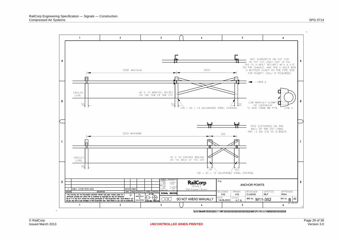
Pipe support steel posts shall be typically 100 mm x 50 mm x 10 mm channel, galvanised to AS/NZS 4680 with 450g/m2 coating. Air main brackets should be as per drawings M11-354 and M11-355.
The pipe shall be anchored:
• Every 300 metres on straight runs • Where the main enters/leaves a pit • Where a steel branch, sub main, or steel cross tie intersects with the main • To restrict the movement of any manifold to +/-25mm • Where there are larger offsets or changes of direction the line shall be anchored in
both directions as shown on drawing M11-352
An air main shall be considered to be straight where:
• Its curved to a horizontal or vertical radius greater than 250 metres. • There are minor offsets of 900 mm maximum around abutments or structures
Use of structures for anchor points shall be subject to approval.
RailCorp Engineering Specification — Signals — Construction Compressed Air Systems SPG 0714
© RailCorp Page 17 of 39 Issued March 2013 UNCONTROLLED WHEN PRINTED Version 3.0
6.3 Cleaning Prior to cleaning, all inlets to equipment that may get blocked during cleaning shall be protected using removable in-line strainers. These strainers shall be removed upon the completion of cleaning. The Installer must ensure that line mounted items likely to be damaged by the cleaning are removed. The Installer shall supply, install and remove any temporary closures required.
Cleaning shall consist of air blowing the pipework at a sufficient velocity to remove the dirt in the pipe. Such flow shall continue at least 5 minutes and until the pipeline is clean.
Only dry air shall be used for cleaning.
6.4 Safety Equipment The equipment and pipework shall be designed and installed to provide maximum protection and safety for operating and maintenance personnel. Safety equipment shall include signage, guards, access covers, inspection covers, emergency stop equipment, safety interlocks, and other devices as specified or implied or as required by any Statutory Authority having jurisdiction.
6.5 Drainage & Ventilation Pits shall be provided with adequate drainage to a waste water system, or other approved discharge points, to continuously remove stormwater and other liquids; and
Compressor Room shall be provided with adequate drainage to a waste water system, or other containment devices, to control contaminants such as oily water; and
Compressor Room shall be provided with adequate ventilation to maintain recommended compressor operating temperatures and room air balance – louvres, ridge vents and other building openings shall utilise acoustic louvres. Other noise attenuation devices shall also be supplied to comply with noise criteria.
EPA approvals shall be obtained for the proposed waste water arrangements.
6.6 Control & Maintainers System A system to permit the control and remote monitoring of the air system & its performance shall be developed & installed.
This system shall include:
• Analogue display of pressure. • Visual and audible alarms. • Schematic diagram VDU display showing all main elements of the system & their
status. • Power supply status. • Compressor and dryer status and alarms. • Logging of all events.
The indications shall be available in the compressor room, and at least one remote site through a TCP/IP interface. The system shall be expandable to permit other remote sites to be added.
A non interruptible power supply shall ensure the continued functioning of the control and maintainers system when the power is interrupted or failed.
RailCorp Engineering Specification — Signals — Construction Compressed Air Systems SPG 0714
© RailCorp Page 18 of 39 Issued March 2013 UNCONTROLLED WHEN PRINTED Version 3.0
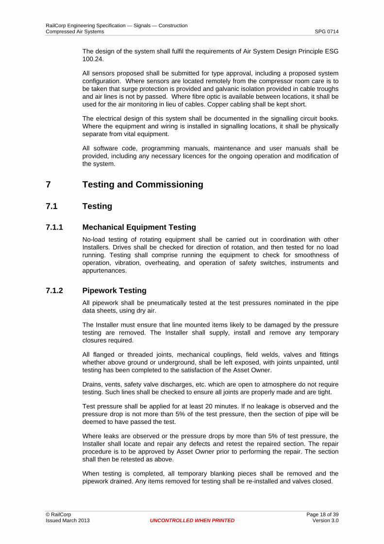
The design of the system shall fulfil the requirements of Air System Design Principle ESG 100.24.
All sensors proposed shall be submitted for type approval, including a proposed system configuration. Where sensors are located remotely from the compressor room care is to be taken that surge protection is provided and galvanic isolation provided in cable troughs and air lines is not by passed. Where fibre optic is available between locations, it shall be used for the air monitoring in lieu of cables. Copper cabling shall be kept short.
The electrical design of this system shall be documented in the signalling circuit books. Where the equipment and wiring is installed in signalling locations, it shall be physically separate from vital equipment.
All software code, programming manuals, maintenance and user manuals shall be provided, including any necessary licences for the ongoing operation and modification of the system.
7 Testing and Commissioning
7.1 Testing
7.1.1 Mechanical Equipment Testing No-load testing of rotating equipment shall be carried out in coordination with other Installers. Drives shall be checked for direction of rotation, and then tested for no load running. Testing shall comprise running the equipment to check for smoothness of operation, vibration, overheating, and operation of safety switches, instruments and appurtenances.
7.1.2 Pipework Testing All pipework shall be pneumatically tested at the test pressures nominated in the pipe data sheets, using dry air.
The Installer must ensure that line mounted items likely to be damaged by the pressure testing are removed. The Installer shall supply, install and remove any temporary closures required.
All flanged or threaded joints, mechanical couplings, field welds, valves and fittings whether above ground or underground, shall be left exposed, with joints unpainted, until testing has been completed to the satisfaction of the Asset Owner.
Drains, vents, safety valve discharges, etc. which are open to atmosphere do not require testing. Such lines shall be checked to ensure all joints are properly made and are tight.
Test pressure shall be applied for at least 20 minutes. If no leakage is observed and the pressure drop is not more than 5% of the test pressure, then the section of pipe will be deemed to have passed the test.
Where leaks are observed or the pressure drops by more than 5% of test pressure, the Installer shall locate and repair any defects and retest the repaired section. The repair procedure is to be approved by Asset Owner prior to performing the repair. The section shall then be retested as above.
When testing is completed, all temporary blanking pieces shall be removed and the pipework drained. Any items removed for testing shall be re-installed and valves closed.
RailCorp Engineering Specification — Signals — Construction Compressed Air Systems SPG 0714
© RailCorp Page 19 of 39 Issued March 2013 UNCONTROLLED WHEN PRINTED Version 3.0
Written records of all tests shall be retained and these and any test certificates shall be forwarded to the Asset Owner and shall in addition be included in the operation and maintenance manuals.
7.1.3 System Testing A System Testing Plan shall be provided to test that the design concepts have been achieved in the installed system. The Test Plan shall itemise each design criteria and the method of testing for each criteria.
Examples of the testing to be conducted include:
Time to reach working pressure from empty.
Line flow restrictors perform as expected.
All monitoring points are functional.
All compressor on / off controls are proved to function at the correct pressures.
All labelling is correct to design.
All electrical changeovers function as designed
The test plan shall be independently verified and submitted for approval.
Testing shall be conducted in the presence of the asset owner.
The results of all testing shall be recorded and submitted to the asset owner.
Testing shall include all functions remotely monitored by the Maintainers VDU. Where analogue monitoring is provided (such as pressure) the testing shall include calibration & correct correspondence through the pressure range between system limits.
Any tests that failed to meet the design criteria shall have the design reviewed and appropriate corrective action agreed with the asset owner.
7.2 Precommissioning The Installer shall precommission the equipment in all operation modes.
Precommissioning is the running of the plant and equipment and carrying out all necessary adjustments until it is ready and suitable for normal starting and running under service conditions.
Precommissioning shall be conducted in a logical sequence in accordance with the programme prepared by the Installer and approved by the Asset Owner. The Installer shall prepare schedules and record the results of the tests on the appropriate log sheets.
The Installer shall furnish the Asset Owner with a complete list of control instrument set points and alarm signal settings recommended by the Installer as a result of his precommissioning programme. These recommended settings may be supplied progressively during the precommissioning period but no later than at the end of the period.
7.3 Commissioning Commissioning is the running of the plant and equipment and carrying out all necessary adjustments until it runs under service condition from part to full load.
RailCorp Engineering Specification — Signals — Construction Compressed Air Systems SPG 0714
© RailCorp Page 20 of 39 Issued March 2013 UNCONTROLLED WHEN PRINTED Version 3.0
Commissioning shall include the tuning of interacting components of control loops to achieve the required control response.
Where equipment items or systems are duplicated in the design to provide “Running” and “Stand-by” facilities, all items of equipment and/or systems of both the “Running” and “Stand-by” facilities shall be fully tested and commissioned.
At completion of commissioning, acceptance certificate as per SPG 0711 is to be completed.
RailCorp Engineering Specification — Signals — Construction Compressed Air Systems SPG 0714
© RailCorp Page 21 of 39 Issued March 2013 UNCONTROLLED WHEN PRINTED Version 3.0
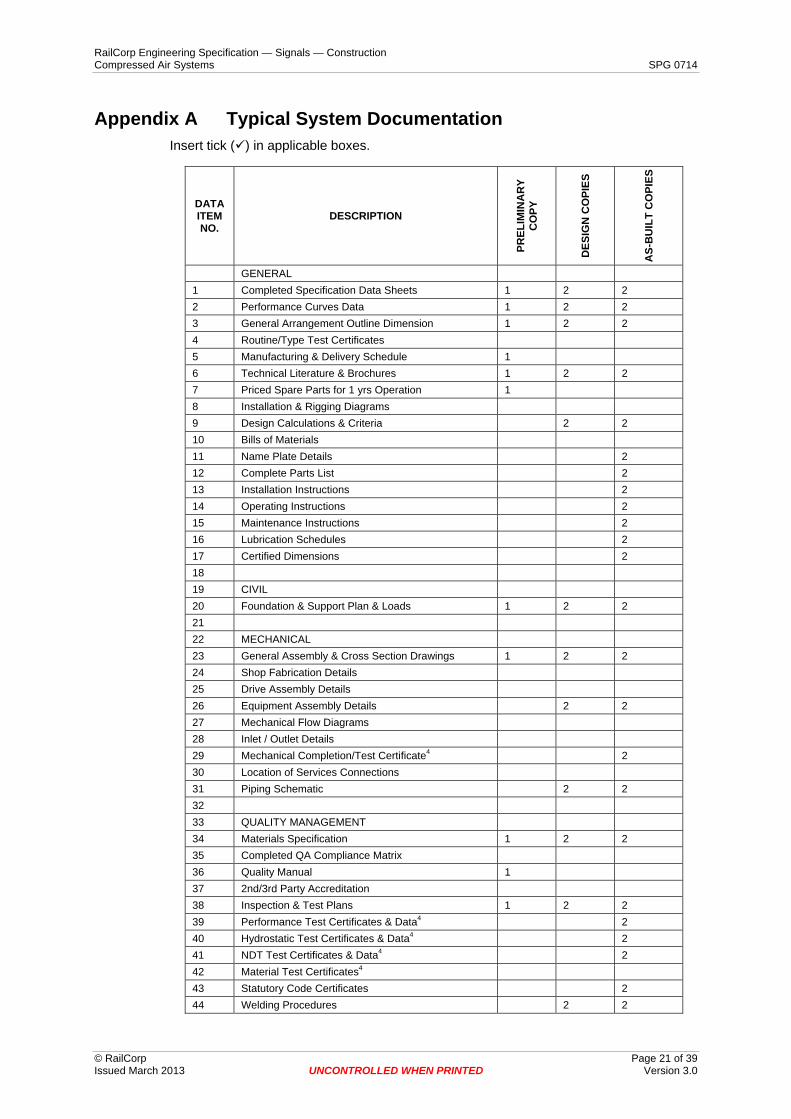
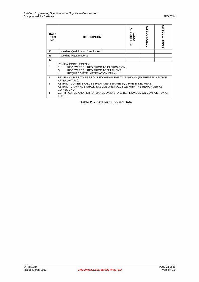
Appendix A Typical System Documentation Insert tick ( ) in applicable boxes.
DATA ITEM NO.
DESCRIPTION
PREL
IMIN
AR
Y C
OPY
DES
IGN
CO
PIES
AS-
BU
ILT
CO
PIES
GENERAL 1 Completed Specification Data Sheets 1 2 2 2 Performance Curves Data 1 2 2 3 General Arrangement Outline Dimension 1 2 2 4 Routine/Type Test Certificates 5 Manufacturing & Delivery Schedule 1 6 Technical Literature & Brochures 1 2 2 7 Priced Spare Parts for 1 yrs Operation 1 8 Installation & Rigging Diagrams 9 Design Calculations & Criteria 2 2 10 Bills of Materials 11 Name Plate Details 2 12 Complete Parts List 2 13 Installation Instructions 2 14 Operating Instructions 2 15 Maintenance Instructions 2 16 Lubrication Schedules 2 17 Certified Dimensions 2 18 19 CIVIL 20 Foundation & Support Plan & Loads 1 2 2 21 22 MECHANICAL 23 General Assembly & Cross Section Drawings 1 2 2 24 Shop Fabrication Details 25 Drive Assembly Details 26 Equipment Assembly Details 2 2 27 Mechanical Flow Diagrams 28 Inlet / Outlet Details 29 Mechanical Completion/Test Certificate4 2 30 Location of Services Connections 31 Piping Schematic 2 2 32 33 QUALITY MANAGEMENT 34 Materials Specification 1 2 2 35 Completed QA Compliance Matrix 36 Quality Manual 1 37 2nd/3rd Party Accreditation 38 Inspection & Test Plans 1 2 2 39 Performance Test Certificates & Data4 2 40 Hydrostatic Test Certificates & Data4 2 41 NDT Test Certificates & Data4 2 42 Material Test Certificates4 43 Statutory Code Certificates 2 44 Welding Procedures 2 2
RailCorp Engineering Specification — Signals — Construction Compressed Air Systems SPG 0714
© RailCorp Page 22 of 39 Issued March 2013 UNCONTROLLED WHEN PRINTED Version 3.0
AS-
BU
ILT
CO
PIES
DATA ITEM NO.
DESCRIPTION
PREL
IMIN
AR
Y C
OPY
DES
IGN
CO
PIES
45 Welders Qualification Certificates4 46 Welding Maps/Records 47 1 REVIEW CODE LEGEND: F: REVIEW REQUIRED PRIOR TO FABRICATION. S: REVIEW REQUIRED PRIOR TO SHIPMENT. I: REQUIRED FOR INFORMATION ONLY. 2 REVIEW COPIES TO BE PROVIDED WITHIN THE TIME SHOWN (EXPRESSED AS TIME
AFTER AWARD). 3 AS-BUILT COPIES SHALL BE PROVIDED BEFORE EQUIPMENT DELIVERY. AS-BUILT DRAWINGS SHALL INCLUDE ONE FULL SIZE WITH THE REMAINDER A3
COPIES UNO. 4 CERTIFICATES AND PERFORMANCE DATA SHALL BE PROVIDED ON COMPLETION OF
TESTS.
Table 2 - Installer Supplied Data
RailCorp Engineering Specification — Signals — Construction Compressed Air Systems SPG 0714
© RailCorp Page 23 of 39 Issued March 2013 3.0 UNCONTROLLED WHEN PRINTED Version
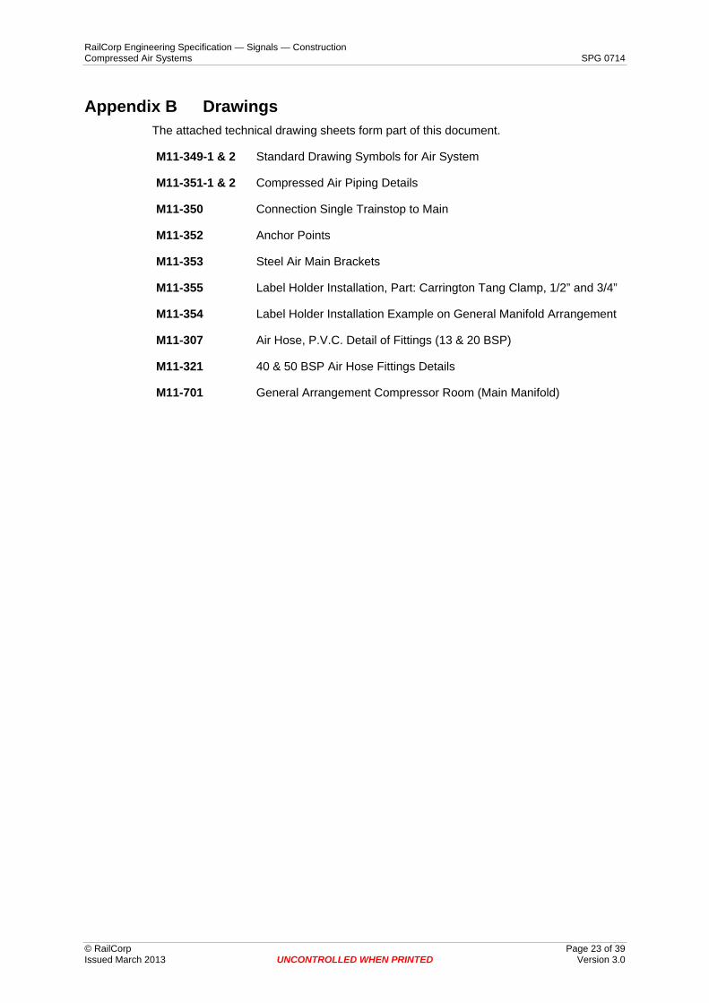
Appendix B Drawings The attached technical drawing sheets form part of this document.
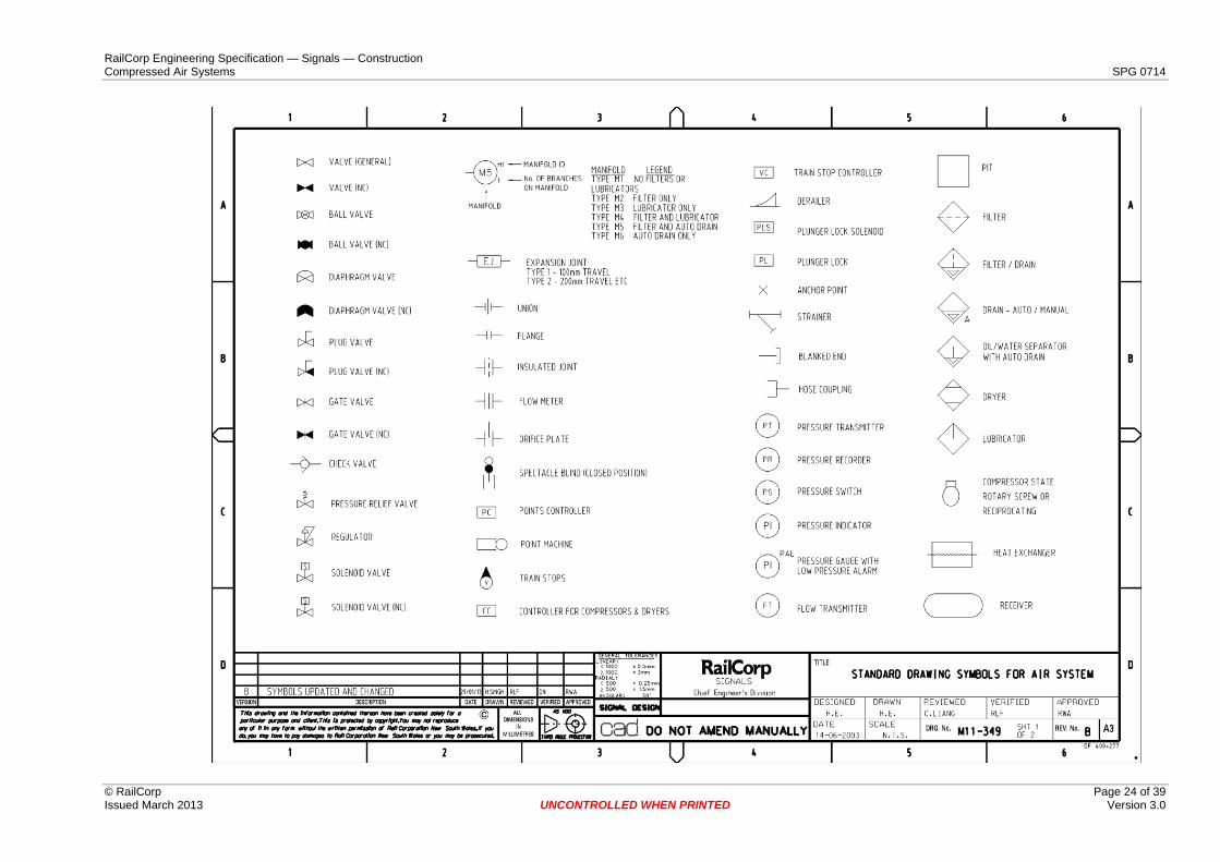
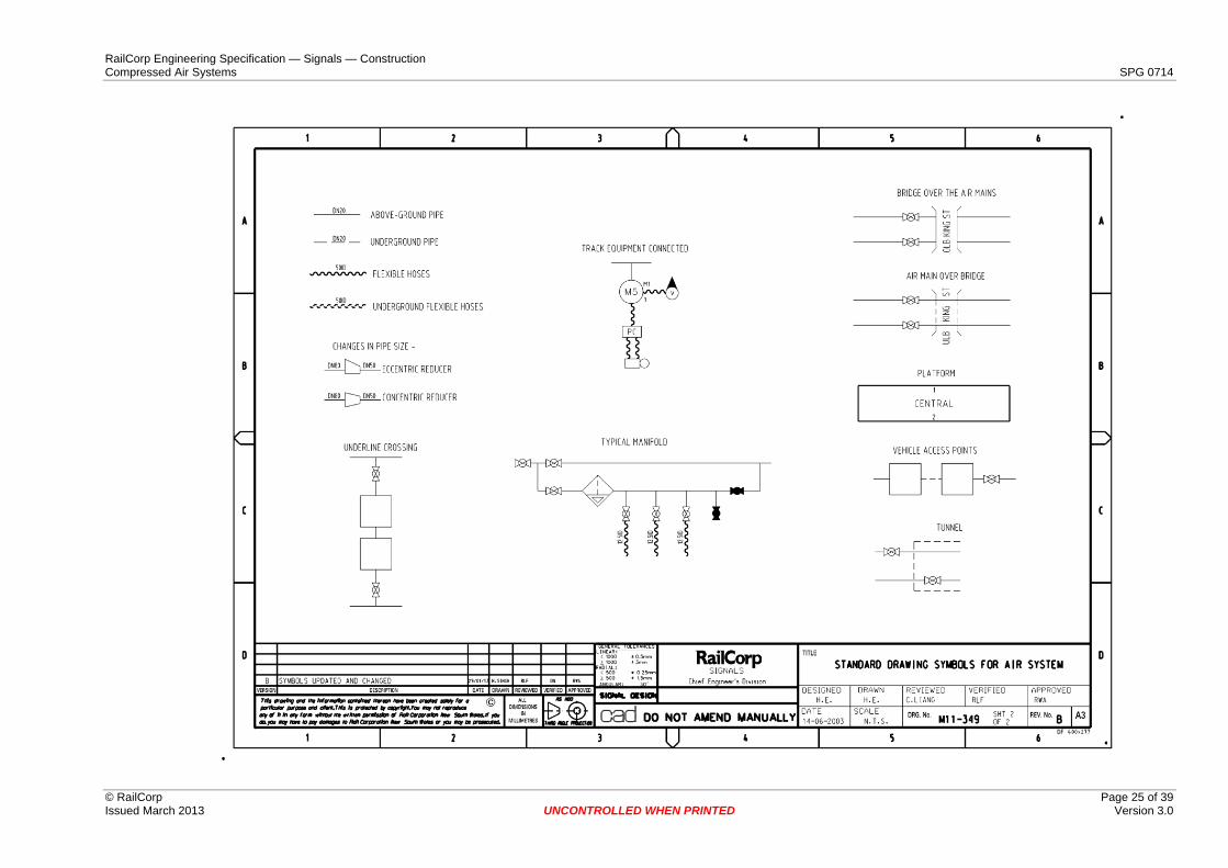
M11-349-1 & 2 Standard Drawing Symbols for Air System
M11-351-1 & 2 Compressed Air Piping Details
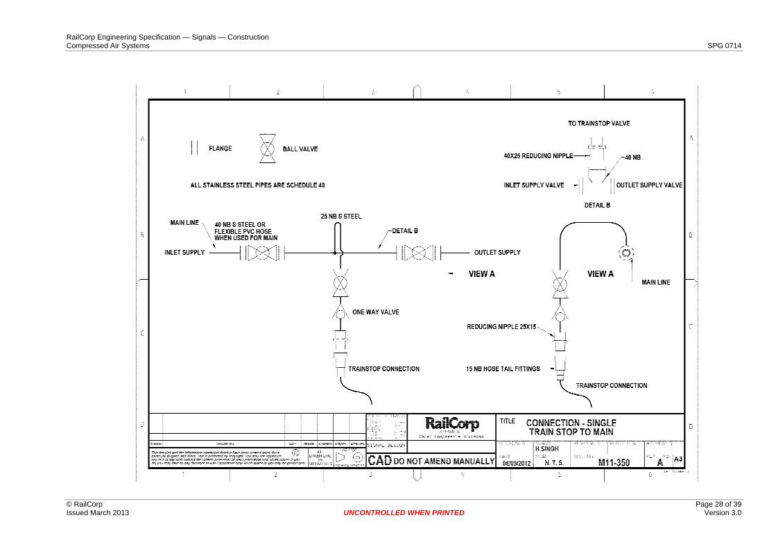
M11-350 Connection Single Trainstop to Main
M11-352 Anchor Points
M11-353 Steel Air Main Brackets
M11-355 Label Holder Installation, Part: Carrington Tang Clamp, 1/2” and 3/4”
M11-354 Label Holder Installation Example on General Manifold Arrangement
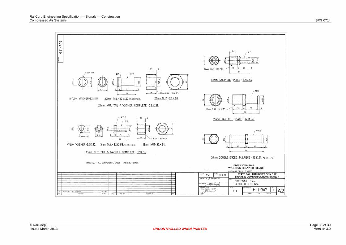
M11-307 Air Hose, P.V.C. Detail of Fittings (13 & 20 BSP)
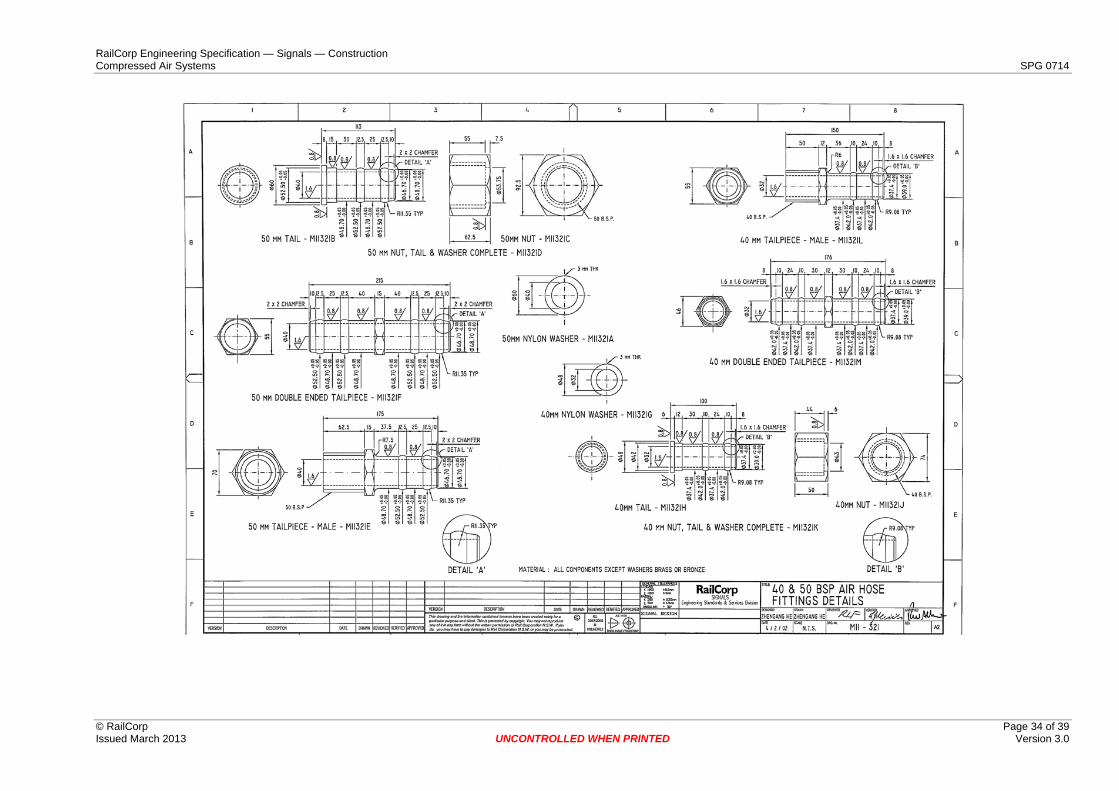
M11-321 40 & 50 BSP Air Hose Fittings Details
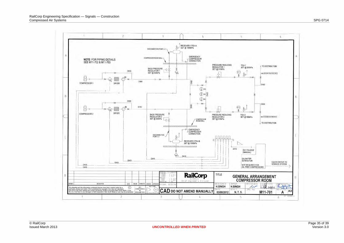
M11-701 General Arrangement Compressor Room (Main Manifold)
RailCorp Engineering Specification — Signals — Construction Compressed Air Systems SPG 0714
© RailCorp Page 24 of 39 Issued March 2013 UNCONTROLLED WHEN PRINTED Version 3.0
RailCorp Engineering Specification — Signals — Construction Compressed Air Systems SPG 0714
© RailCorp Page 25 of 39 Issued March 2013 UNCONTROLLED WHEN PRINTED Version 3.0
RailCorp Engineering Specification — Signals — Construction Compressed Air Systems SPG 0714
© RailCorp Page 26 of 39 Issued March 2013 UNCONTROLLED WHEN PRINTED Version 3.0
RailCorp Engineering Specification — Signals — Construction Compressed Air Systems SPG 0714
© RailCorp Page 27 of 39 Issued March 2013 UNCONTROLLED WHEN PRINTED Version 3.0
RailCorp Engineering Specification — Signals — Construction Compressed Air Systems SPG 0714
© RailCorp Page 28 of 39 Issued March 2013 UNCONTROLLED WHEN PRINTED Version 3.0
RailCorp Engineering Specification — Signals — Construction Compressed Air Systems SPG 0714
© RailCorp Page 29 of 39 Issued March 2013 UNCONTROLLED WHEN PRINTED Version 3.0
RailCorp Engineering Specification — Signals — Construction Compressed Air Systems SPG 0714
© RailCorp Page 30 of 39 Issued March 2013 UNCONTROLLED WHEN PRINTED Version 3.0
RailCorp Engineering Specification — Signals — Construction Compressed Air Systems SPG 0714
© RailCorp Page 31 of 39 Issued March 2013 UNCONTROLLED WHEN PRINTED Version 3.0
RailCorp Engineering Specification — Signals — Construction Compressed Air Systems SPG 0714
© RailCorp Page 32 of 39 Issued March 2013 UNCONTROLLED WHEN PRINTED Version 3.0
RailCorp Engineering Specification — Signals — Construction Compressed Air Systems SPG 0714
© RailCorp Page 33 of 39 Issued March 2013 UNCONTROLLED WHEN PRINTED Version 3.0
RailCorp Engineering Specification — Signals — Construction Compressed Air Systems SPG 0714
© RailCorp Page 34 of 39 Issued March 2013 UNCONTROLLED WHEN PRINTED Version 3.0
RailCorp Engineering Specification — Signals — Construction Compressed Air Systems SPG 0714
© RailCorp Page 35 of 39 Issued March 2013 Version 3.0
UNCONTROLLED WHEN PRINTED
RailCorp Engineering Specification — Signals — Construction Compressed Air Systems SPG 0714
© RailCorp Page 36 of 39 Issued March 2013 UNCONTROLLED WHEN PRINTED Version 3.0
Appendix C Data Sheets The attached data sheets form part of this document.
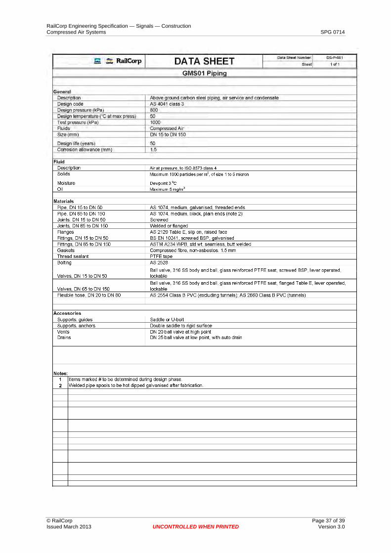
DS-P-001 GMS01 Piping
DS-P-002 MS01 Piping
DS-P-003 SS01 Piping
RailCorp Engineering Specification — Signals — Construction Compressed Air Systems SPG 0714
© RailCorp Page 37 of 39 Issued March 2013 UNCONTROLLED WHEN PRINTED Version 3.0
RailCorp Engineering Specification — Signals — Construction Compressed Air Systems SPG 0714
© RailCorp Page 38 of 39 Issued March 2013 UNCONTROLLED WHEN PRINTED Version 3.0
RailCorp Engineering Specification — Signals — Construction Compressed Air Systems SPG 0714
© RailCorp Page 39 of 39 Issued March 2013 UNCONTROLLED WHEN PRINTED Version 3.0