Embed Size (px)
Citation preview
Spirit Pro PC User Manual
M/N: 101
Version: 2.1 Revision:A
Date: July 2015
Givat Brenner, 60948, Israel.
Tel: +972-8-9443961 Fax: +972-8-9443357
E-mail: [email protected] Website: http://www.gavishcontrol.com

Introduction
Spirit Pro PC User Guide II
Copyright Notice
This publication contains proprietary information belonging to Gavish control systems LTD.,
a Jain irrigation company. This information is supplied only to assist explicitly and properly
authorized users of Gavish control systems LTD.
No part of this document may be used for any other purpose, disclosed to any person or
firm, or reproduced by any means, electronic and mechanical, without the express prior
written permission of Gavish control systems LTD.
The text and graphics are for illustration and reference only. The specifications on which
they are based are subject to change without notice.
No part of this publication is part of any contract or warranty unless specifically
incorporated by reference into such contract or warranty.
The information in this publication is only descriptive in nature, and is not a binding offer for
the sale of the product described herein.
Information in this publication is subject to change without notice. Corporate and individual
names and data used in examples herein are fictitious unless otherwise noted.
Gavish control systems LTD reserves the right to alter the equipment specifications and
descriptions in this publication without prior notice.
© 2015 Gavish control systems LTD., a Jain irrigation company. All rights reserved.
Introduction
Spirit Pro PC User Guide III
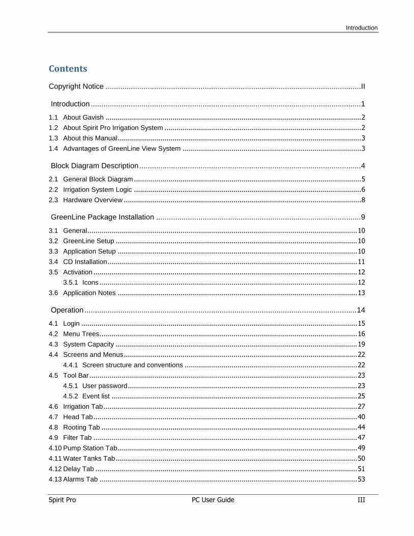
Contents
Copyright Notice ......................................................................................................................... II
Introduction ................................................................................................................................ 1
1.1 About Gavish .............................................................................................................................. 2
1.2 About Spirit Pro Irrigation System ................................................................................................. 2
1.3 About this Manual ........................................................................................................................ 3
1.4 Advantages of GreenLine View System ........................................................................................ 3
Block Diagram Description ......................................................................................................... 4
2.1 General Block Diagram ................................................................................................................ 5
2.2 Irrigation System Logic ................................................................................................................ 6
2.3 Hardware Overview ..................................................................................................................... 8
GreenLine Package Installation ................................................................................................. 9
3.1 General ..................................................................................................................................... 10
3.2 GreenLine Setup ....................................................................................................................... 10
3.3 Application Setup ...................................................................................................................... 10
3.4 CD Installation ........................................................................................................................... 11
3.5 Activation .................................................................................................................................. 12
3.5.1 Icons ............................................................................................................................... 12
3.6 Application Notes ...................................................................................................................... 13
Operation ................................................................................................................................. 14
4.1 Login ........................................................................................................................................ 15
4.2 Menu Trees ............................................................................................................................... 16
4.3 System Capacity ....................................................................................................................... 19
4.4 Screens and Menus ................................................................................................................... 22
4.4.1 Screen structure and conventions ..................................................................................... 22
4.5 Tool Bar .................................................................................................................................... 23
4.5.1 User password ................................................................................................................. 23
4.5.2 Event list ......................................................................................................................... 25
4.6 Irrigation Tab ............................................................................................................................. 27
4.7 Head Tab .................................................................................................................................. 40
4.8 Rooting Tab .............................................................................................................................. 44
4.9 Filter Tab .................................................................................................................................. 47
4.10 Pump Station Tab ...................................................................................................................... 49
4.11 Water Tanks Tab ....................................................................................................................... 50
4.12 Delay Tab ................................................................................................................................. 51
4.13 Alarms Tab ............................................................................................................................... 53
Introduction
Spirit Pro PC User Guide IV
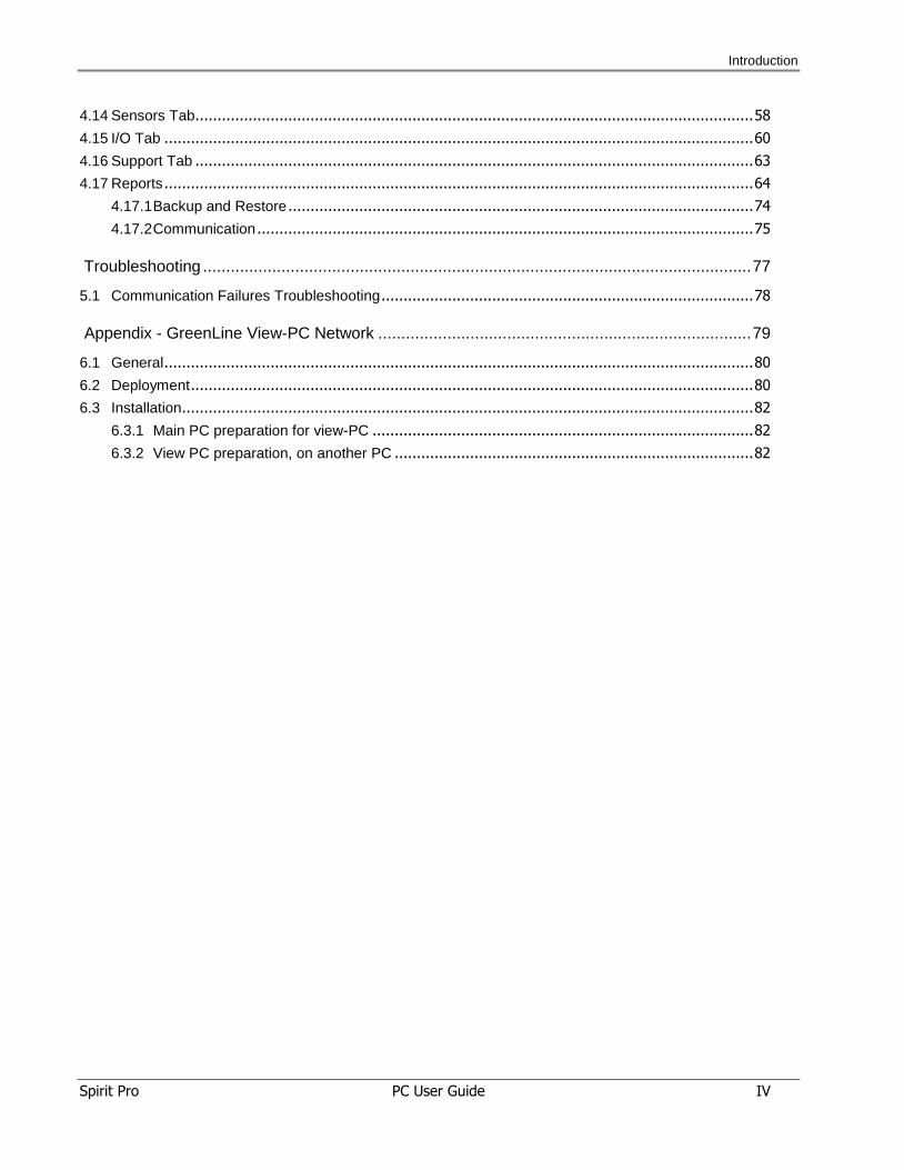
4.14 Sensors Tab .............................................................................................................................. 58
4.15 I/O Tab ..................................................................................................................................... 60
4.16 Support Tab .............................................................................................................................. 63
4.17 Reports ..................................................................................................................................... 64
4.17.1 Backup and Restore ......................................................................................................... 74
4.17.2 Communication ................................................................................................................ 75
Troubleshooting ....................................................................................................................... 77
5.1 Communication Failures Troubleshooting .................................................................................... 78
Appendix - GreenLine View-PC Network ................................................................................. 79
6.1 General ..................................................................................................................................... 80
6.2 Deployment ............................................................................................................................... 80
6.3 Installation................................................................................................................................. 82
6.3.1 Main PC preparation for view-PC ...................................................................................... 82
6.3.2 View PC preparation, on another PC ................................................................................. 82
Introduction
Spirit Pro PC User Guide V
List of Figures Figure 2-1: General System Block Diagram .............................................................................. 5 Figure 2-2: Irrigation System Overview ..................................................................................... 7 Figure 2-3: Hardware Structure of the Irrigation System ............................................................. 8 Figure 3-1: GreenLine Setup CD Window ................................................................................ 11 Figure 4-1: Irrigation Control Screen ....................................................................................... 15 Figure 4-2: Irrigation Tab Menu Tree ....................................................................................... 16 Figure 4-3: Head Tab Menu Tree ............................................................................................ 16 Figure 4-4: Rooting Tab Menu Tree ........................................................................................ 16 Figure 4-5: Filter Tab Menu Tree ............................................................................................ 16 Figure 4-6: Pump Station Tab Menu Tree ................................................................................ 17 Figure 4-7: Delay Tab Menu Tree ........................................................................................... 17 Figure 4-8: Alarms Tab Menu Tree ......................................................................................... 17 Figure 4-9: Sensors Tab Menu Tree ........................................................................................ 17 Figure 4-10: I/O Tab Menu Tree ............................................................................................. 18 Figure 4-11: Support Menu Tree ............................................................................................. 18 Figure 4-12: Screen Structure ................................................................................................ 22 Figure 4-13: User Password Window ...................................................................................... 23 Figure 4-14: User List Window................................................................................................ 24 Figure 4-15: Event List Window .............................................................................................. 25 Figure 4-16: Irrigation Heads Screen ....................................................................................... 27 Figure 4-17: Irrigation Consumption Screen ............................................................................. 28 Figure 4-18: Consumption Report Screen ................................................................................ 28 Figure 4-19: Programs Screen................................................................................................ 30 Figure 4-20: Fertilization Programs Screen .............................................................................. 34 Figure 4-21: Fert Level Screen ............................................................................................... 36 Figure 4-22: Flow Definitions Screen ....................................................................................... 36 Figure 4-23: General Screen .................................................................................................. 37 Figure 4-24: Tensiometer Screen ............................................................................................ 39 Figure 4-25: Irrigation Head Screen ........................................................................................ 40 Figure 4-26: Fert Level Screen ............................................................................................... 41 Figure 4-27: Flow Definitions Screen ....................................................................................... 42 Figure 4-28: Sensor Screen ................................................................................................... 43 Figure 4-29: Rooting Irrigation Definition Screen ...................................................................... 44 Figure 4-30: Rooting Time Period Screen ................................................................................ 46 Figure 4-31: Filters Screen ..................................................................................................... 47 Figure 4-32: Pump Station Screen .......................................................................................... 49 Figure 4-33: Tank Definitions.................................................................................................. 50 Figure 4-34: Delays Screen .................................................................................................... 51 Figure 4-35: Irrigation Alarms Screen ...................................................................................... 53 Figure 4-36: Alarms Screen.................................................................................................... 54 Figure 4-37: Alarms History Screen ........................................................................................ 55 Figure 4-38: SMS Screen ....................................................................................................... 56 Figure 4-39: Sensor Screen ................................................................................................... 58 Figure 4-40: Outputs Screen .................................................................................................. 60 Figure 4-41: Digital Input Screen ............................................................................................ 61 Figure 4-42: Analog Input Screen ........................................................................................... 61 Figure 4-43: I/O Card Interface ............................................................................................... 62 Figure 4-44: Technical Support Screen ................................................................................... 63 Figure 4-45: Graph List Window ............................................................................................. 64 Figure 4-46: EC/pH Graph Window ......................................................................................... 65
Introduction
Spirit Pro PC User Guide VI
Figure 4-47: Graph Definitions Window ................................................................................... 66 Figure 4-48: Variables List ..................................................................................................... 67 Figure 4-49: Subject/Equipment Tabs ..................................................................................... 67 Figure 4-50: Line Parameters Window .................................................................................... 68 Figure 4-51: Log Reports Window .......................................................................................... 70 Figure 4-52: Periodic Reports Window .................................................................................... 71 Figure 4-53: Application Messages Window ............................................................................ 72 Figure 4-54: Communication Messages Window ...................................................................... 73 Figure 4-55: Clean Window ................................................................................................... 73 Figure 4-56: Backup and Restore Window .............................................................................. 74 Figure 4-57: Communication Window ..................................................................................... 75 Figure 4-58: Communication Setup Window ............................................................................ 76 Figure 6-1: Single View Deployment ....................................................................................... 81 Figure 6-2: Multi View-PC Deployment ................................................................................... 81

Spirit Pro PC User Guide 1
1 IInnttrroodduuccttiioonn
Introduction
Spirit Pro PC User Guide 2
1.1 About Gavish
GAVISH control systems, a Jain irrigation company, is a leading manufacturer of control
systems for the agricultural market. We produce software and hardware to operate,
monitor and control many functions within greenhouses, dairy farms and fish farms.
GAVISH's three major product lines are: GreenLine, DairyLine and AquaLine.
Since 1980, GAVISH has developed and supplied computerized electronic systems to the
agricultural industry throughout the world. GAVISH's products are widely used in many
countries, including Australia, Japan, China, France, Ethiopia, Kenya, Mexico and other
countries.
GAVISH's control systems enhance efficiency and productivity of the farm.
Our products use advanced technology controlled by a user-friendly Human Machine
Interface (HMI) developed by GAVISH control systems. GAVISH's control systems are open
systems that you can easily install, integrate, operate and update.
Computerized fertigation and irrigation systems of GAVISH control systems improve crop
yields and maximize your revenue.
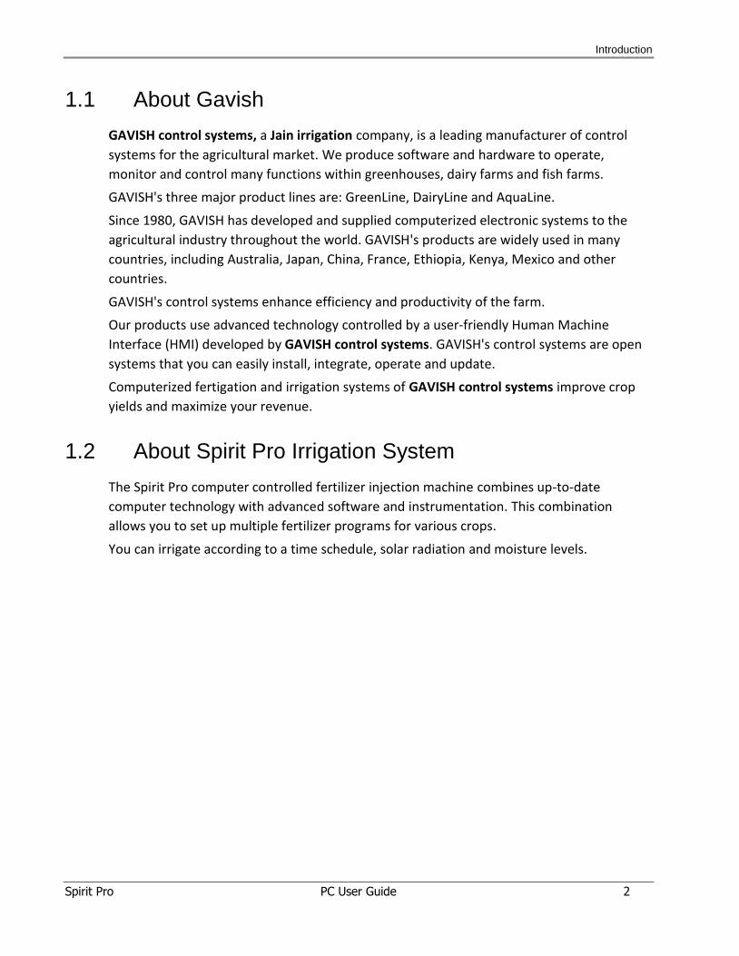
1.2 About Spirit Pro Irrigation System
The Spirit Pro computer controlled fertilizer injection machine combines up-to-date
computer technology with advanced software and instrumentation. This combination
allows you to set up multiple fertilizer programs for various crops.
You can irrigate according to a time schedule, solar radiation and moisture levels.
Introduction
Spirit Pro PC User Guide 3
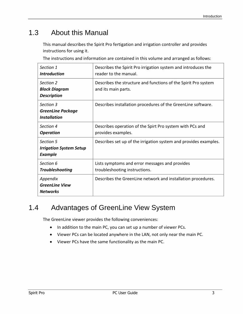
1.3 About this Manual
This manual describes the Spirit Pro fertigation and irrigation controller and provides
instructions for using it.
The instructions and information are contained in this volume and arranged as follows:
1.4 Advantages of GreenLine View System
The GreenLine viewer provides the following conveniences:
In addition to the main PC, you can set up a number of viewer PCs.
Viewer PCs can be located anywhere in the LAN, not only near the main PC.
Viewer PCs have the same functionality as the main PC.
Section 1
Introduction
Describes the Spirit Pro irrigation system and introduces the
reader to the manual.
Section 2
Block Diagram
Description
Describes the structure and functions of the Spirit Pro system
and its main parts.
Section 3
GreenLine Package
Installation
Describes installation procedures of the GreenLine software.
Section 4
Operation
Describes operation of the Spirt Pro system with PCs and
provides examples.
Section 5
Irrigation System Setup
Example
Describes set up of the irrigation system and provides examples.
Section 6
Troubleshooting
Lists symptoms and error messages and provides
troubleshooting instructions.
Appendix
GreenLine View
Networks
Describes the GreenLine network and installation procedures.
Block Diagram Description
Spirit Pro PC User Guide 4
2 BBlloocckk DDiiaaggrraamm DDeessccrriipptt iioonn
Block Diagram Description
Spirit Pro PC User Guide 5
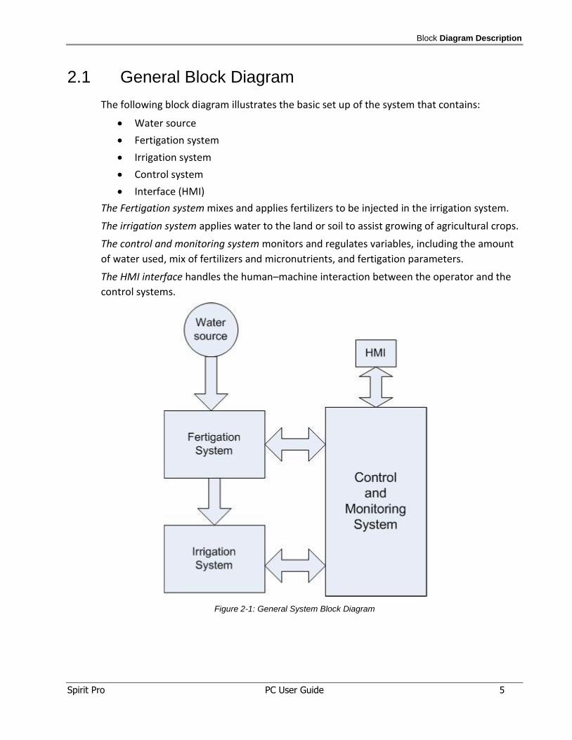
2.1 General Block Diagram
The following block diagram illustrates the basic set up of the system that contains:
Water source
Fertigation system
Irrigation system
Control system
Interface (HMI)
The Fertigation system mixes and applies fertilizers to be injected in the irrigation system.
The irrigation system applies water to the land or soil to assist growing of agricultural crops.
The control and monitoring system monitors and regulates variables, including the amount
of water used, mix of fertilizers and micronutrients, and fertigation parameters.
The HMI interface handles the human–machine interaction between the operator and the
control systems.
Figure 2-1: General System Block Diagram
Block Diagram Description
Spirit Pro PC User Guide 6
2.2 Irrigation System Logic
A multi-channel fertigation machine improves the efficiency and accuracy of water-nutrient
mixing. The hardware includes a programmable logic controller (PLC), a panel interface
system and multi-channel sensors.
A sectional forecast control algorithm based on the nutrient dilution model controls the
fertigation machine.
The irrigation program is based on one or more of the following variables:
Time and duration of watering
Quantity of irrigation water
Fertilization program
Weather conditions
Soil type and water potential
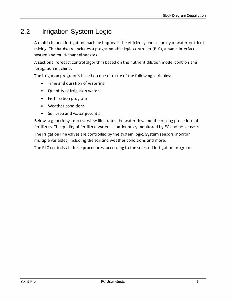
Below, a generic system overview illustrates the water flow and the mixing procedure of
fertilizers. The quality of fertilized water is continuously monitored by EC and pH sensors.
The irrigation line valves are controlled by the system logic. System sensors monitor
multiple variables, including the soil and weather conditions and more.
The PLC controls all these procedures, according to the selected fertigation program.
Block Diagram Description
Spirit Pro PC User Guide 7
Figure 2-2: Irrigation System Overview
Block Diagram Description
Spirit Pro PC User Guide 8
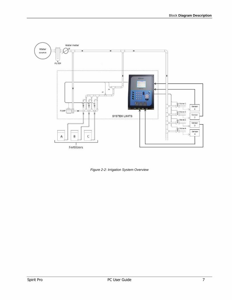
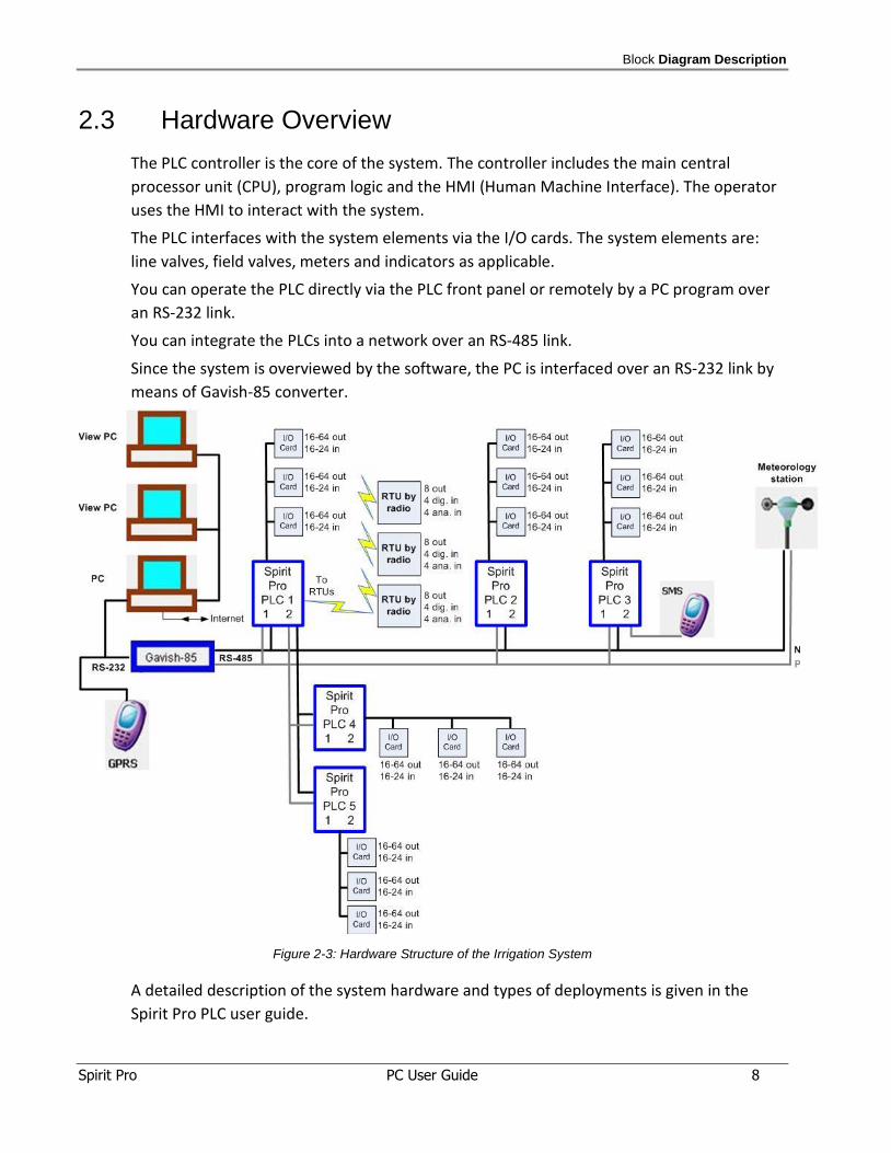
2.3 Hardware Overview
The PLC controller is the core of the system. The controller includes the main central
processor unit (CPU), program logic and the HMI (Human Machine Interface). The operator
uses the HMI to interact with the system.
The PLC interfaces with the system elements via the I/O cards. The system elements are:
line valves, field valves, meters and indicators as applicable.
You can operate the PLC directly via the PLC front panel or remotely by a PC program over
an RS-232 link.
You can integrate the PLCs into a network over an RS-485 link.
Since the system is overviewed by the software, the PC is interfaced over an RS-232 link by
means of Gavish-85 converter.
Figure 2-3: Hardware Structure of the Irrigation System
A detailed description of the system hardware and types of deployments is given in the
Spirit Pro PLC user guide.

GreenLine Package Installation
Spirit Pro PC User Guide 9
3 GGrreeeennLLiinnee PPaacckkaaggee IInnssttaall llaattiioonn
GreenLine Package Installation
Spirit Pro PC User Guide 10
3.1 General
This section provides information to install the GreenLine application.
Minimal PC requirement:
CPU: Intel i3, Ram: 2/4 Gb, Hard disk space: 40 Gb,
Operating system: Windows 7/8/XP 64/32 bit, 2 USB 2.0 ports,
Graphic display 1024x768, CD drive.
The GreenLine Package CD contains two programs:
GreenLine setup program
Application setup program
You may also download these programs from Gavish Web files site:
http://www.gavishcontrol.com
Enter to Support.
Enter to GreenLine folder for updated GreenLine setup.
Enter to Applic folder for application update.
3.2 GreenLine Setup
The GreenLine setup program actually installs the GreenLine package. Therefore, you must
install the GreenLine setup program on the site computer before you install the application
setup program. The GreenLine setup program contains the programs which allow the site
computer to run the application.
3.3 Application Setup
"Application" is a user program that performs specific tasks. "Application" includes specific
menus and displays, formulas, PLCs, graphs and reports.
Your particular application is hosted at a specific Web address. You receive access to this
address by Email from GAVISH control systems.
GreenLine Package Installation
Spirit Pro PC User Guide 11
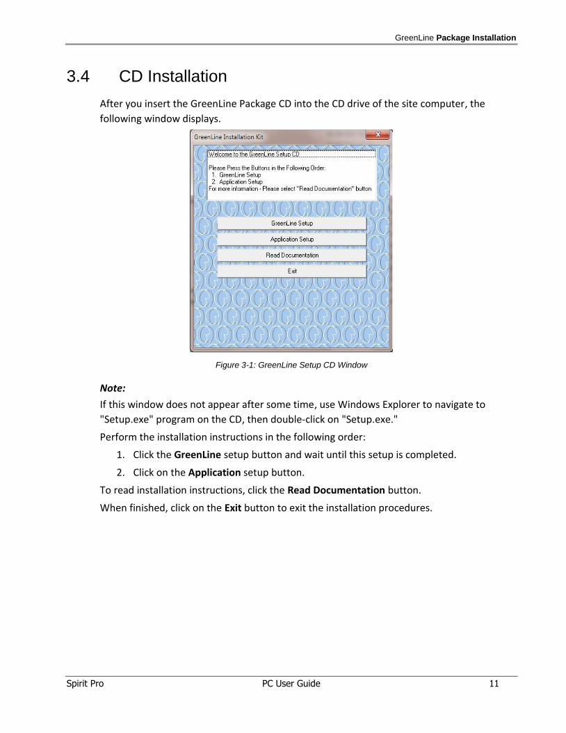
3.4 CD Installation
After you insert the GreenLine Package CD into the CD drive of the site computer, the
following window displays.
Figure 3-1: GreenLine Setup CD Window
Note:
If this window does not appear after some time, use Windows Explorer to navigate to
"Setup.exe" program on the CD, then double-click on "Setup.exe."
Perform the installation instructions in the following order:
1. Click the GreenLine setup button and wait until this setup is completed.
2. Click on the Application setup button.
To read installation instructions, click the Read Documentation button.
When finished, click on the Exit button to exit the installation procedures.
GreenLine Package Installation
Spirit Pro PC User Guide 12
3.5 Activation
To activate the application, double click the GreenLine Application icon on the desktop (or
reboot the computer).
During program initialization, the program startup picture and then the application itself will
appear on the screen.
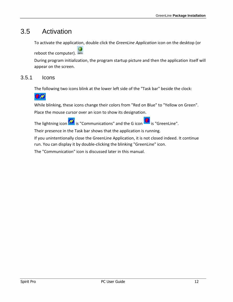
3.5.1 Icons
The following two icons blink at the lower left side of the "Task bar" beside the clock:
While blinking, these icons change their colors from "Red on Blue" to "Yellow on Green".
Place the mouse cursor over an icon to show its designation.
The lightning icon is "Communications" and the G icon is "GreenLine".
Their presence in the Task bar shows that the application is running.
If you unintentionally close the GreenLine Application, it is not closed indeed. It continue
run. You can display it by double-clicking the blinking "GreenLine" icon.
The "Communication" icon is discussed later in this manual.
GreenLine Package Installation
Spirit Pro PC User Guide 13
3.6 Application Notes
The GreenLine system contains two main control tools:
The PLCs
The PC (optional)
The "real" control operations are performed at the PLCs network. The PLCs read the
sensors, share information with other PLCs on the network, and activate relays according to
their programming.
The GreenLine Application is the user interface running on the PC. You use it for "Data
acquisition" purposes. It does not control the GreenLine system.
The PC reads the required data from the PLCs via a network method.
A word for Gavish dealers (only):
If you store several applications on the dealer computer, it is important to prevent mixing of
files between them.
We recommend for the dealer the following procedure:
Please note: The installation program installs all applications at the same "Applic" folder.
To store several customer applications on your computer without mixing their files –always
rename the "Applic" folder after the installation. If you want to update an existing
application, first delete the application folder with all of its content from your computer,
then install the updated application, and now rename the "Applic" folder to this name.
In order to activate an application, enter its folder, and double-click the icon named "1
GreenLine".
Operation
Spirit Pro PC User Guide 14
4 OOppeerraattiioonn
Operation
Spirit Pro PC User Guide 15
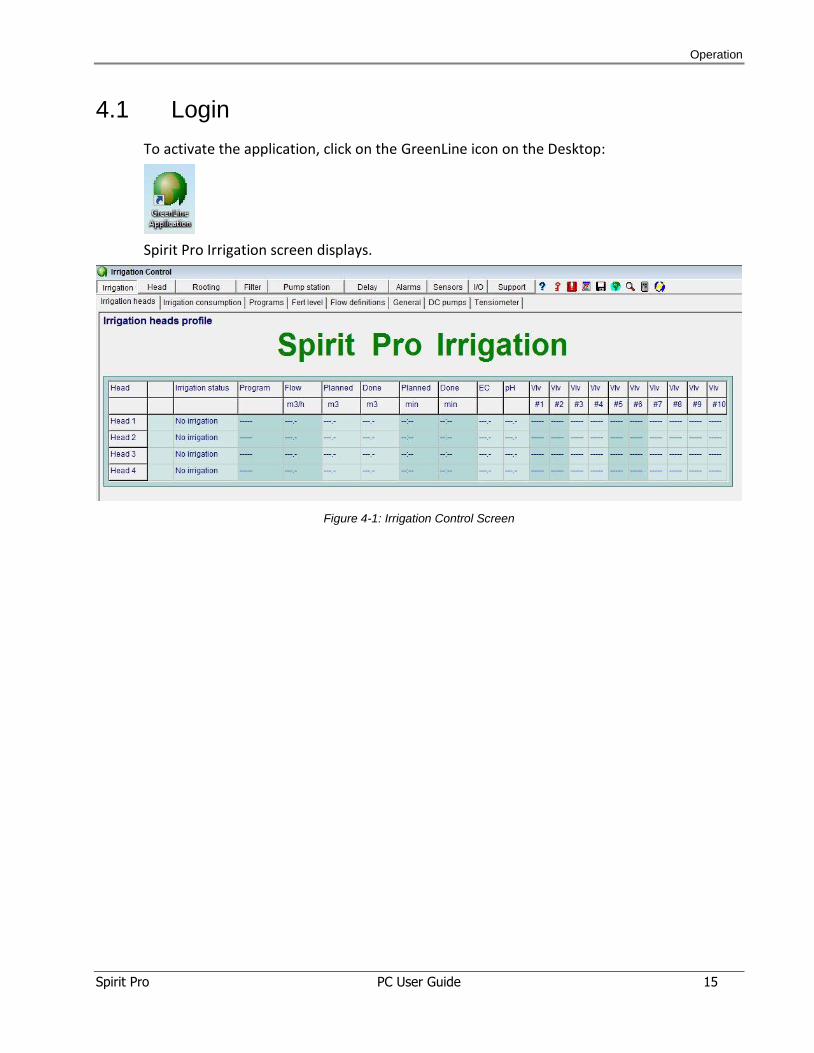
4.1 Login
To activate the application, click on the GreenLine icon on the Desktop:
Spirit Pro Irrigation screen displays.
Figure 4-1: Irrigation Control Screen
Operation
Spirit Pro PC User Guide 16
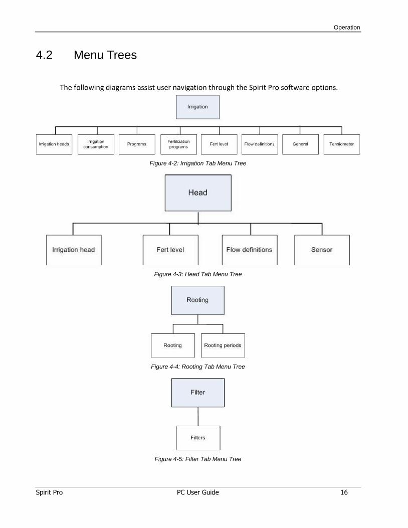
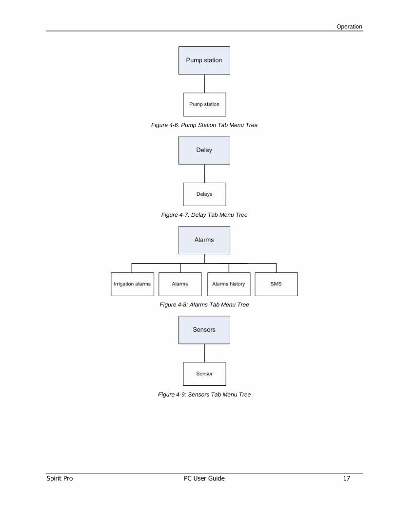
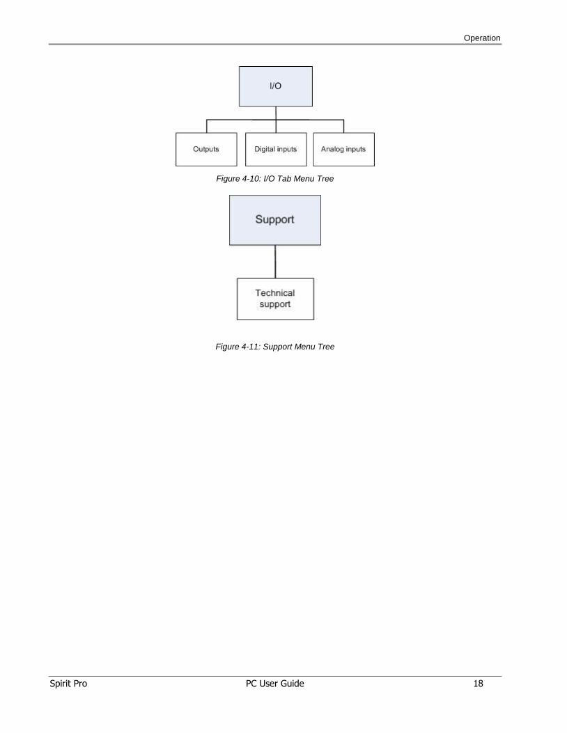
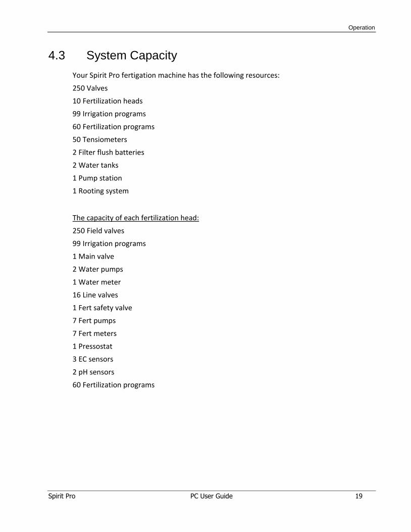
4.2 Menu Trees
The following diagrams assist user navigation through the Spirit Pro software options.
Figure 4-2: Irrigation Tab Menu Tree
Figure 4-3: Head Tab Menu Tree
Figure 4-4: Rooting Tab Menu Tree
Figure 4-5: Filter Tab Menu Tree
Operation
Spirit Pro PC User Guide 17
Figure 4-6: Pump Station Tab Menu Tree
Figure 4-7: Delay Tab Menu Tree
Figure 4-8: Alarms Tab Menu Tree
Figure 4-9: Sensors Tab Menu Tree
Operation
Spirit Pro PC User Guide 18
Figure 4-10: I/O Tab Menu Tree
Figure 4-11: Support Menu Tree
Operation
Spirit Pro PC User Guide 19
4.3 System Capacity
Your Spirit Pro fertigation machine has the following resources:
250 Valves
10 Fertilization heads
99 Irrigation programs
60 Fertilization programs
50 Tensiometers
2 Filter flush batteries
2 Water tanks
1 Pump station
1 Rooting system
The capacity of each fertilization head:
250 Field valves
99 Irrigation programs
1 Main valve
2 Water pumps
1 Water meter
16 Line valves
1 Fert safety valve
7 Fert pumps
7 Fert meters
1 Pressostat
3 EC sensors
2 pH sensors
60 Fertilization programs
Operation
Spirit Pro PC User Guide 20
The capacity of each Irrigation program:
10 Valves
5 Irrigation schedules
1 Tensiometer
In each filter battery:
10 Filters
1 Downstream Valve
1 DP sensor
In each tank:
1 High float
1 Low float
1 Water level sensor
Pump station includes:
5 Water pumps
1 Water meter
1 Pressostat
The capacity of a rooting system:
80 rooting valves
1 Main rooting valve
1 Water meter
1 Pressostat
1 Conditional contact
Operation
Spirit Pro PC User Guide 21
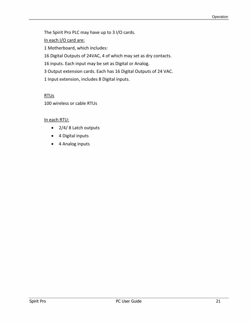
The Spirit Pro PLC may have up to 3 I/O cards.
In each I/O card are:
1 Motherboard, which includes:
16 Digital Outputs of 24VAC, 4 of which may set as dry contacts.
16 inputs. Each input may be set as Digital or Analog.
3 Output extension cards. Each has 16 Digital Outputs of 24 VAC.
1 Input extension, includes 8 Digital inputs.
RTUs
100 wireless or cable RTUs
In each RTU:
2/4/ 8 Latch outputs
4 Digital inputs
4 Analog inputs
Operation
Spirit Pro PC User Guide 22
4.4 Screens and Menus
4.4.1 Screen structure and conventions
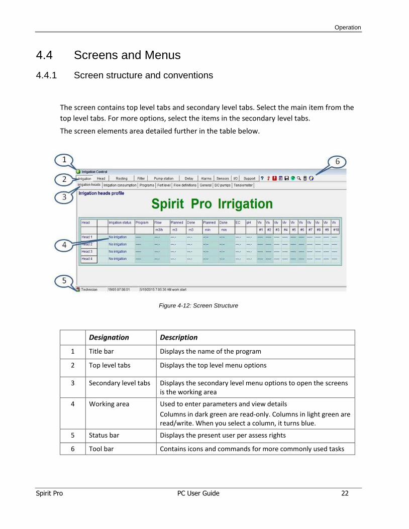
The screen contains top level tabs and secondary level tabs. Select the main item from the
top level tabs. For more options, select the items in the secondary level tabs.
The screen elements area detailed further in the table below.
Figure 4-12: Screen Structure
Designation Description
1 Title bar Displays the name of the program
2 Top level tabs Displays the top level menu options
3 Secondary level tabs Displays the secondary level menu options to open the screens is the working area
4 Working area Used to enter parameters and view details
Columns in dark green are read-only. Columns in light green are read/write. When you select a column, it turns blue.
5 Status bar Displays the present user per assess rights
6 Tool bar Contains icons and commands for more commonly used tasks
Operation
Spirit Pro PC User Guide 23
4.5 Tool Bar
The toolbar contains icons for commonly used tasks as detailed below.
Icon Designation Description
Help
User Password Click to access the system and enter the password. Manager may maintain the user list.
Event List Click to display events (further detailed below).
Reports Click to view graphs and reports (further detailed below).
Backup and restore Click to back up the Spirt Pro database or restore the database (further detailed below).
Language Click to select language version from the dropdown list.
Communication Click to set up communication parameters and view
communication data
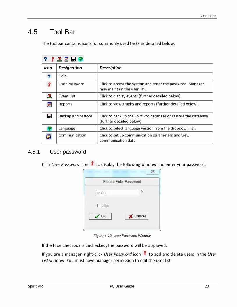
4.5.1 User password
Click User Password icon to display the following window and enter your password.
Figure 4-13: User Password Window
If the Hide checkbox is unchecked, the password will be displayed.
If you are a manager, right-click User Password icon to add and delete users in the User
List window. You must have manager permission to edit the user list.
Operation
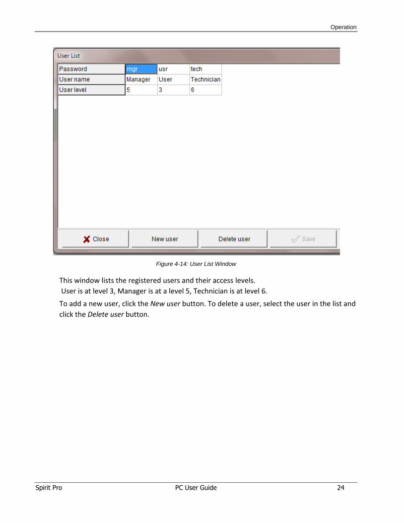
Spirit Pro PC User Guide 24
Figure 4-14: User List Window
This window lists the registered users and their access levels.
User is at level 3, Manager is at a level 5, Technician is at level 6.
To add a new user, click the New user button. To delete a user, select the user in the list and
click the Delete user button.
Operation
Spirit Pro PC User Guide 25
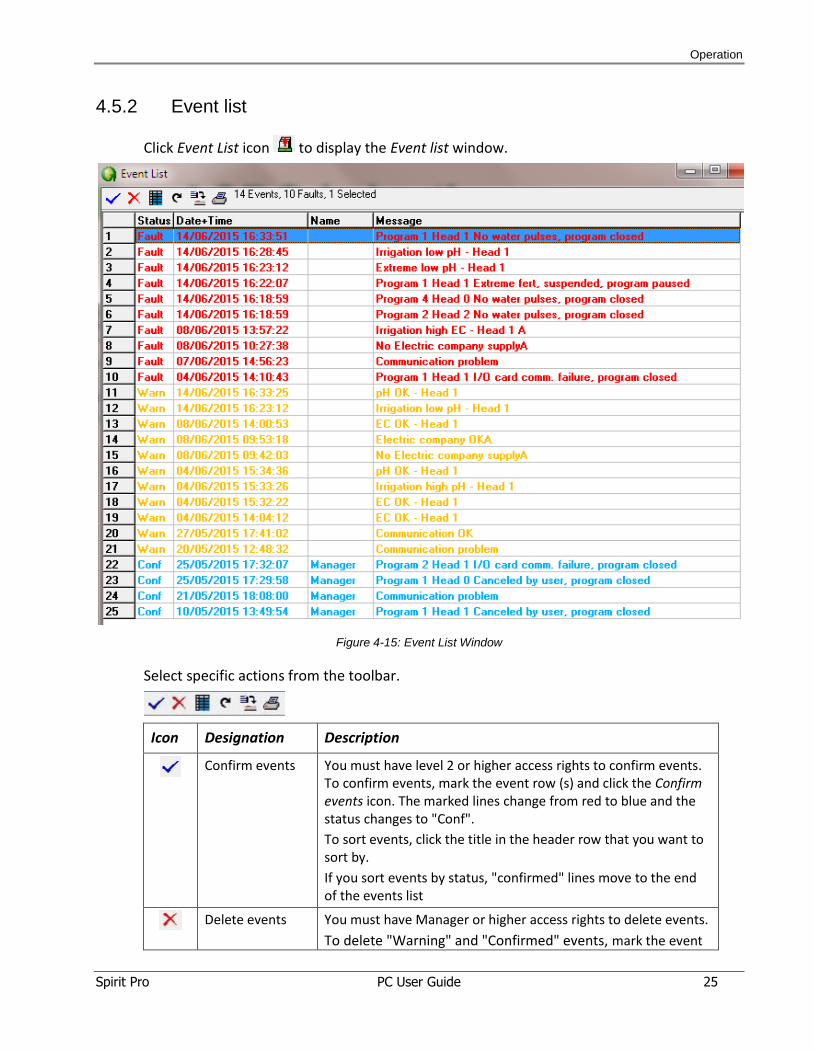
4.5.2 Event list
Click Event List icon to display the Event list window.
Figure 4-15: Event List Window
Select specific actions from the toolbar.
Icon Designation Description
Confirm events You must have level 2 or higher access rights to confirm events.
To confirm events, mark the event row (s) and click the Confirm events icon. The marked lines change from red to blue and the status changes to "Conf".
To sort events, click the title in the header row that you want to sort by.
If you sort events by status, "confirmed" lines move to the end of the events list
Delete events You must have Manager or higher access rights to delete events.
To delete "Warning" and "Confirmed" events, mark the event
Operation
Spirit Pro PC User Guide 26
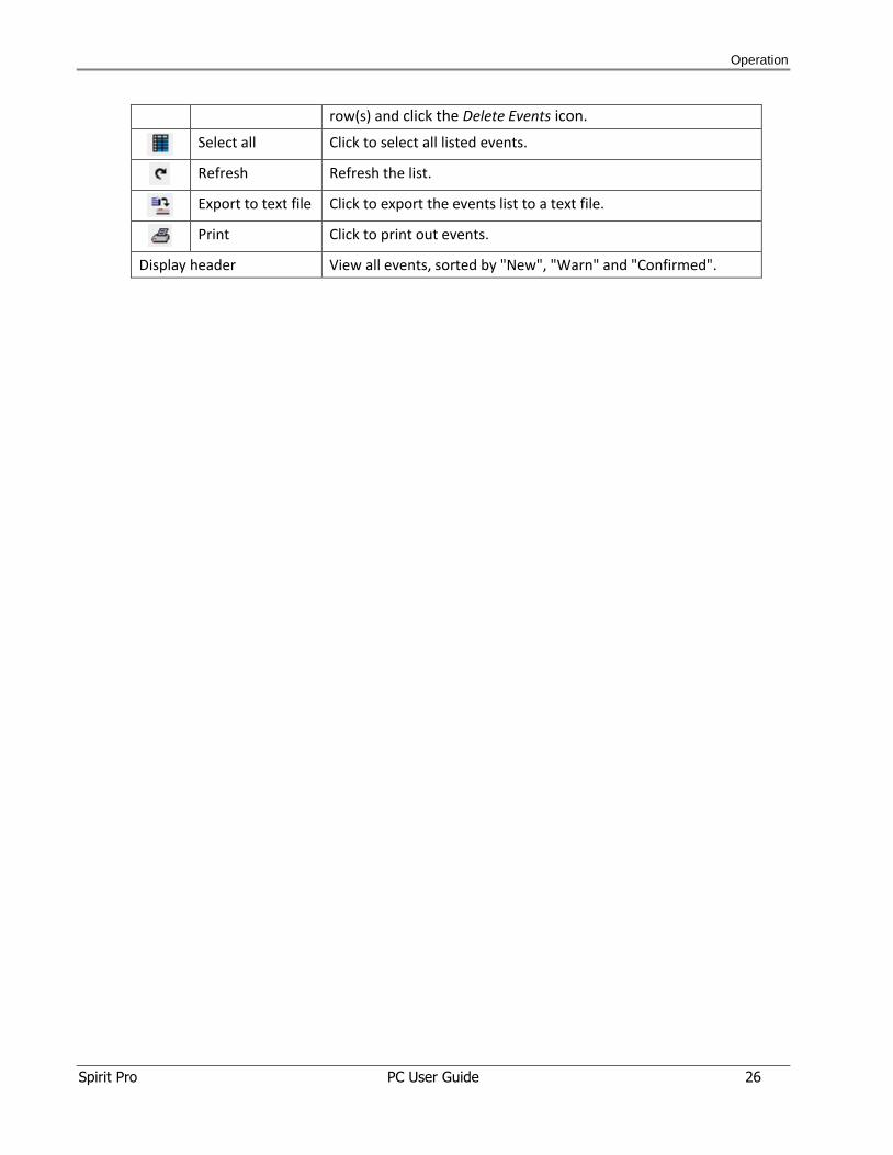
row(s) and click the Delete Events icon.
Select all Click to select all listed events.
Refresh Refresh the list.
Export to text file Click to export the events list to a text file.
Print Click to print out events.
Display header View all events, sorted by "New", "Warn" and "Confirmed".
Operation
Spirit Pro PC User Guide 27
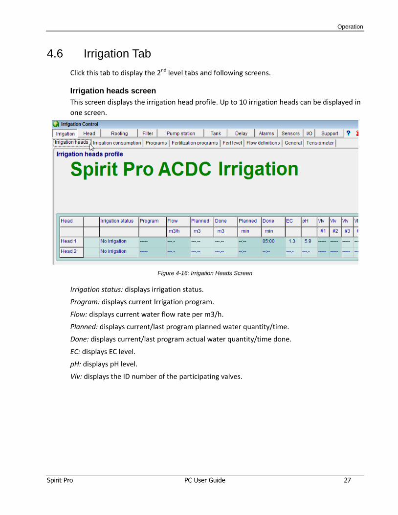
4.6 Irrigation Tab
Click this tab to display the 2nd level tabs and following screens.
Irrigation heads screen
This screen displays the irrigation head profile. Up to 10 irrigation heads can be displayed in
one screen.
Figure 4-16: Irrigation Heads Screen
Irrigation status: displays irrigation status.
Program: displays current Irrigation program.
Flow: displays current water flow rate per m3/h.
Planned: displays current/last program planned water quantity/time.
Done: displays current/last program actual water quantity/time done.
EC: displays EC level.
pH: displays pH level.
Vlv: displays the ID number of the participating valves.
Operation
Spirit Pro PC User Guide 28
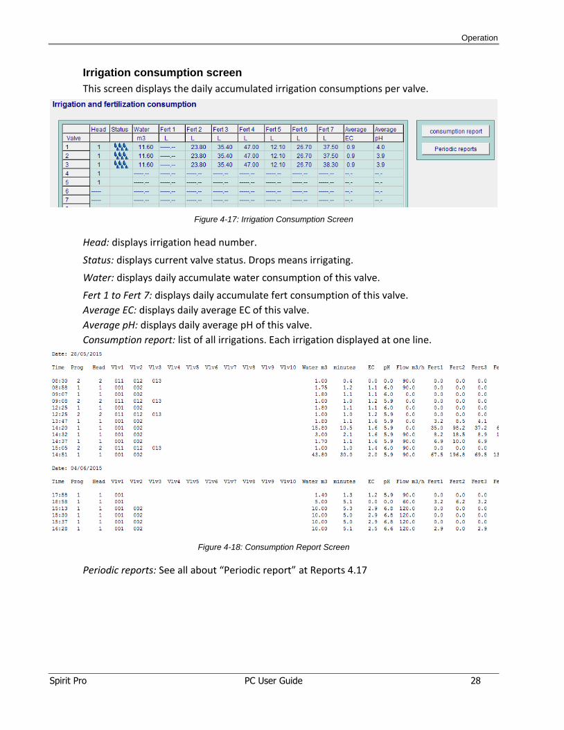
Irrigation consumption screen
This screen displays the daily accumulated irrigation consumptions per valve.
Figure 4-17: Irrigation Consumption Screen
Head: displays irrigation head number.
Status: displays current valve status. Drops means irrigating.
Water: displays daily accumulate water consumption of this valve.
Fert 1 to Fert 7: displays daily accumulate fert consumption of this valve.
Average EC: displays daily average EC of this valve.
Average pH: displays daily average pH of this valve.
Consumption report: list of all irrigations. Each irrigation displayed at one line.
Figure 4-18: Consumption Report Screen
Periodic reports: See all about “Periodic report” at Reports 4.17
Operation
Spirit Pro PC User Guide 29
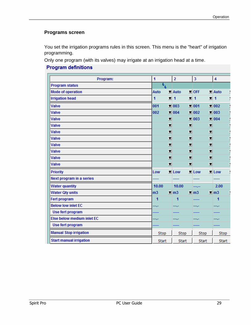
Programs screen
You set the irrigation programs rules in this screen. This menu is the "heart" of irrigation
programming.
Only one program (with its valves) may irrigate at an irrigation head at a time.
Operation
Spirit Pro PC User Guide 30
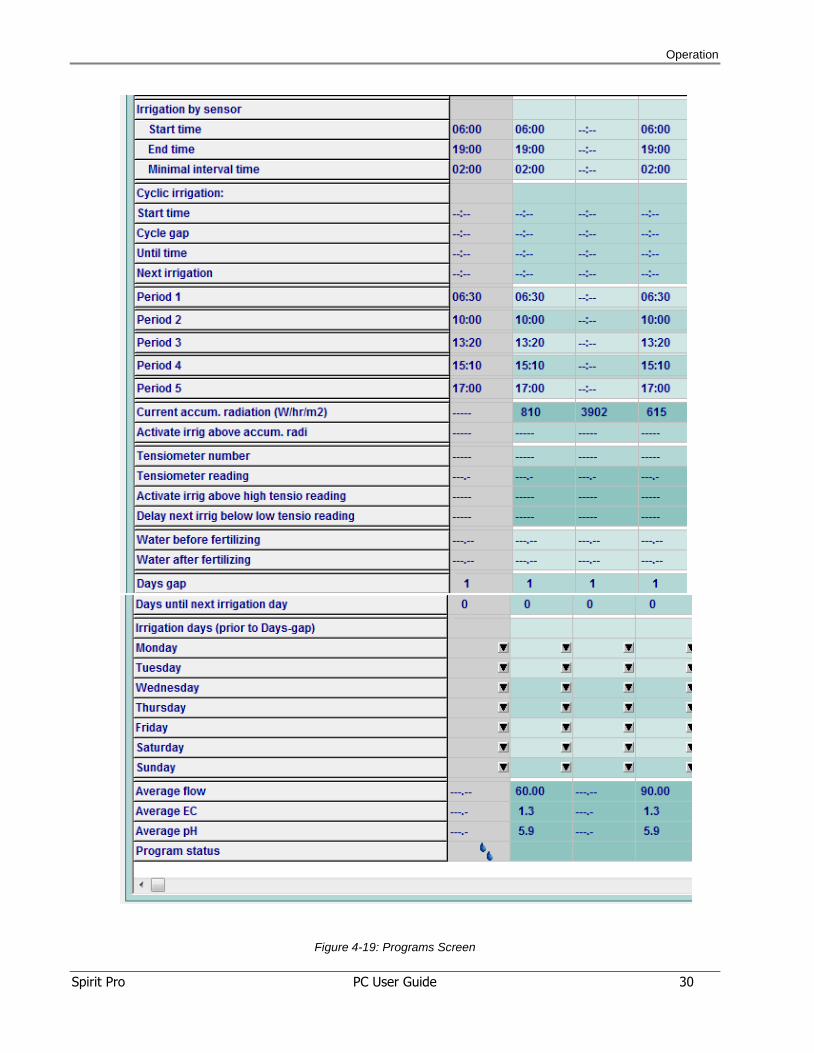
Figure 4-19: Programs Screen
Operation
Spirit Pro PC User Guide 31
Program: number of the irrigation program.
Program status: displays current status of the program:
: Program not irrigating now, and not waiting for its turn.
: Program waiting for its turn to start to irrigate.
: Program activated manually, waiting for its turn to start to irrigate
: Program irrigates now.
Mode of operation: Auto, Off, or Followed.
OFF: The program activates only by “Manual” command.
Auto: The program activates automatically, according to its definitions.
Followed: The program starts working only if activated by another program.
Irrigation head: irrigation head number.
Valve: these valves are activated together when the program is running. The program
divides water and fert quantities between valves, according to valves nominal flow ratio.
Right click to enter the valves list.
Priority: select Low, Medium or High. Right click to display the dropdown list
Priority defines which program in the queue – will be activated first.
If priority is equal for all programs, the program waiting longest starts first.
Medium priority program is prior to Low priority programs.
A High priority program suspends lower-priority programs. A High priority program does not suspend running High priority program.
When a suspended program resumes, it resumes from the point that it stopped.
Next program in series: when the irrigation program ends, other programs activate
automatically. Mark the next program as Followed under
Water quantity: enter water quantity for the irrigations.
If the quantity units are “m3”: 5.35 means 5 m3 + 350 L.
If the quantity units are “min”: 5.30 means 5 minutes + 30 seconds.
Water quantity units: enter a dropdown list to set quantity measurement units (m3, min)
for the irrigation.
Fert program: enter the number of the fertilizing program.
Below low inlet EC, Use fert program: At irrigation start, if the inlet EC level drops below the
entered threshold, use fert program as defined at Use fert. Program (at next line).
Else below medium inlet EC, Use fert program: if, at irrigation start, the inlet EC level drops
below the entered threshold, use fert program as defined at Use fert. Program (at next line).
Operation
Spirit Pro PC User Guide 32
Manual stop irrigation: click to stop current irrigation manually. It stops running or waiting
irrigation.
Start manual irrigation: click to start irrigation manually.
Irrigation by sensor: irrigation is controlled by sensor
Start time: from this time – irrigation starts when allowed by sensor
End time: from this time – irrigation starts if is not allowed by sensor.
Minimal interval time: Minimal time interval between -irrigation- program ends to next
start of irrigation program the by sensor.
Cyclic irrigation:
Start time: Set daily start time for cyclic irrigation. Start time = 0 means "no cyclic
irrigation".
Cycle gap: set the required time interval (hours and minutes) between irrigation cycles.
Until time: set end time to start a cyclic irrigation.
Next irrigation: displays calculated start time for next cyclic irrigation. This time may be
changed manually.
Schedule irrigations:
Period 1 .. Period 5: Set irrigation start times.
Irrigation by radiation:
Current accum. radiation (W-hr/m2): displays radiation accumulated since the last time this
program started.
Activate irrig above accum. radi: input of accumulated radiation level (since the last time
this program started) above which a cyclic irrigation is activated.
Irrigation by tensiometer:
Tensiometer number: enter the number of the Tensiometer that controls this program.
Next three fields are “read only”. You may set its value at “Tensiometers” screen.
Tensiometer reading: display tensiometer readout.
Activate irrig above high tension reading: display the high Tensiometer reading, above
which an irrigation is activated.
Delay next irrig below low tension reading: displays the low tensiometer reading, below
which the next irrigation is delayed.
Water before fertilizing: “Pre-wash” Water quantity (in terms of water Qty units defined
above) at irrigation start – without fertilizing.
Water after fertilizing: “After-wash” water quantity without fertilizing - towards irrigation
end.
Days gap: enter interval days required between irrigation days. For “every day” enter 1.
Operation
Spirit Pro PC User Guide 33
Days until next irrigation day: enter days until next irrigation day. “0” means: “an Irrigation
day”. This number reduced automatically by 1 - every midnight.
Days of the week: You may define few days of the week as “irrigation days”.
Note:
It is allowed to use both methods. The results will be as defined.
The last three lines (Average flow, Average EC, Average pH) are the average of the
current/last irrigation.
Program status: displays current program status. (equals to first line of this screen)
Operation
Spirit Pro PC User Guide 34
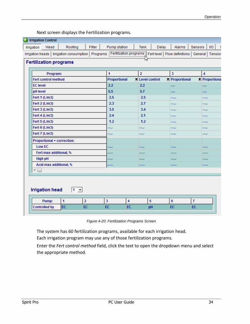
Next screen displays the Fertilization programs.
Figure 4-20: Fertilization Programs Screen
The system has 60 fertilization programs, available for each irrigation head.
Each irrigation program may use any of those fertilization programs.
Enter the Fert control method field, click the text to open the dropdown menu and select
the appropriate method.
Operation
Spirit Pro PC User Guide 35
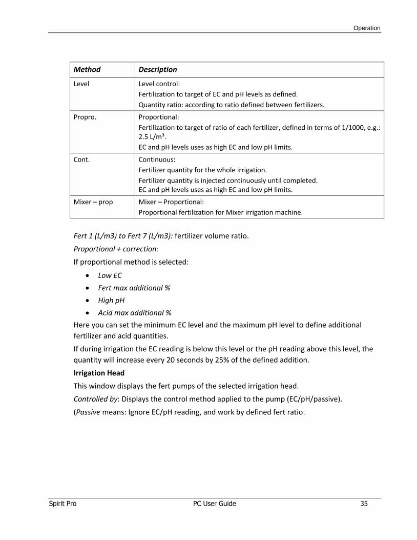
Method Description
Level Level control:
Fertilization to target of EC and pH levels as defined.
Quantity ratio: according to ratio defined between fertilizers.
Propro. Proportional:
Fertilization to target of ratio of each fertilizer, defined in terms of 1/1000, e.g.: 2.5 L/m³.
EC and pH levels uses as high EC and low pH limits.
Cont. Continuous:
Fertilizer quantity for the whole irrigation.
Fertilizer quantity is injected continuously until completed. EC and pH levels uses as high EC and low pH limits.
Mixer – prop Mixer – Proportional:
Proportional fertilization for Mixer irrigation machine.
Fert 1 (L/m3) to Fert 7 (L/m3): fertilizer volume ratio.
Proportional + correction:
If proportional method is selected:
Low EC
Fert max additional %
High pH
Acid max additional %
Here you can set the minimum EC level and the maximum pH level to define additional
fertilizer and acid quantities.
If during irrigation the EC reading is below this level or the pH reading above this level, the
quantity will increase every 20 seconds by 25% of the defined addition.
Irrigation Head
This window displays the fert pumps of the selected irrigation head.
Controlled by: Displays the control method applied to the pump (EC/pH/passive).
(Passive means: Ignore EC/pH reading, and work by defined fert ratio.
Operation
Spirit Pro PC User Guide 36
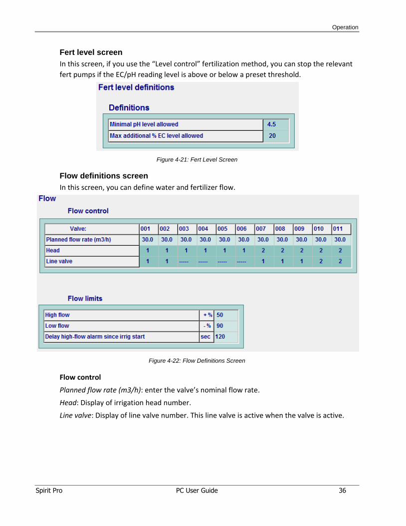
Fert level screen
In this screen, if you use the “Level control” fertilization method, you can stop the relevant
fert pumps if the EC/pH reading level is above or below a preset threshold.
Figure 4-21: Fert Level Screen
Flow definitions screen
In this screen, you can define water and fertilizer flow.
Figure 4-22: Flow Definitions Screen
Flow control
Planned flow rate (m3/h): enter the valve’s nominal flow rate.
Head: Display of irrigation head number.
Line valve: Display of line valve number. This line valve is active when the valve is active.

Operation
Spirit Pro PC User Guide 37
Flow limits
High Flow: enter the percentage increase above nominal flow rate that defines a "High
Flow" event.
"0" = "Do not check for high flow".
Low Flow: enter the percentage decrease below nominal flow that defines a "Low Flow"
event.
"0" = "Do not check for low flow".
General screen
The following screen enables you to define general parameters for irrigation.
Figure 4-23: General Screen
Announce if fert quantity is less by: define missing fert ratio that causes an alarm.
Delay change valve status: define the delay time (in seconds) before changing valve status
from Open to Close (or the opposite).
Operation
Spirit Pro PC User Guide 38
Wait for first water pulse, before fertilizing: set Yes or No to wait for the 1st water pulse (at
irrigation start) before fertilizer pumps start.
Max wait time for first pulse: maximal wait time for first water pulse. After this time the
irrigation stops, with alarm of “No first pulse”.
Pause irrigation during filter flush: select Yes or No to pause the irrigation when filter flush is
activated.
Activate additional pump above high flow: at irrigation head with two water pumps,
activate the second pump above this flow rate.
Stop additional pump below low flow: stop additional pump operation if flow is low.
Prevent vacuum pump below flow: stop vacuum pump operation if flow is below the preset
threshold.
Resume irrigation after failure, within __: enter delay time to resume irrigation after low
flow or no water failure.
Increase/decrease water quantity: enter a percentage that multiplies water quantity. Useful
for unusually hot or cold days.
Stop irrigation if extreme fert levels: define extreme fert event. Fert event is extreme when
a reading surpasses the threshold level for above the time defined.
Extreme high EC: extreme high EC level.
Extreme low EC: extreme low EC level.
Extreme high pH: extreme high pH level.
Extreme low pH: extreme low pH level.
For more than: activate only if the threshold level exceeds the set number of seconds.
Resume from extreme fert event, after: set delay time to automatically resume fertigation
during Extreme fert event.
Max reiterations of resume from extreme fert event: enter the maximum number of
automatic attempts to resume irrigation.
Operation
Spirit Pro PC User Guide 39
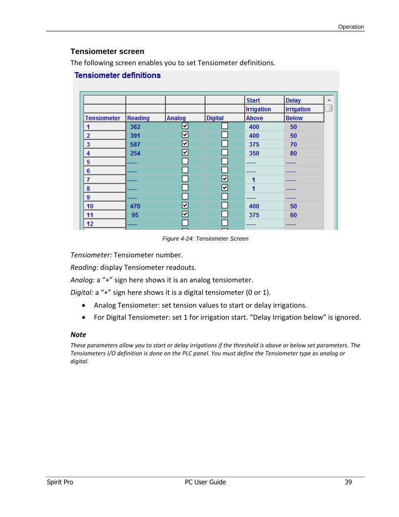
Tensiometer screen
The following screen enables you to set Tensiometer definitions.
Figure 4-24: Tensiometer Screen
Tensiometer: Tensiometer number.
Reading: display Tensiometer readouts.
Analog: a “+” sign here shows it is an analog tensiometer.
Digital: a “+” sign here shows it is a digital tensiometer (0 or 1).
Analog Tensiometer: set tension values to start or delay irrigations.
For Digital Tensiometer: set 1 for irrigation start. “Delay Irrigation below” is ignored.
Note
These parameters allow you to start or delay irrigations if the threshold is above or below set parameters. The Tensiometers I/O definition is done on the PLC panel. You must define the Tensiometer type as analog or digital.
Operation
Spirit Pro PC User Guide 40
4.7 Head Tab
Head tab is a visual display of subjects related to irrigation heads.
The following screens are displayed in the 2nd level tabs under Head.
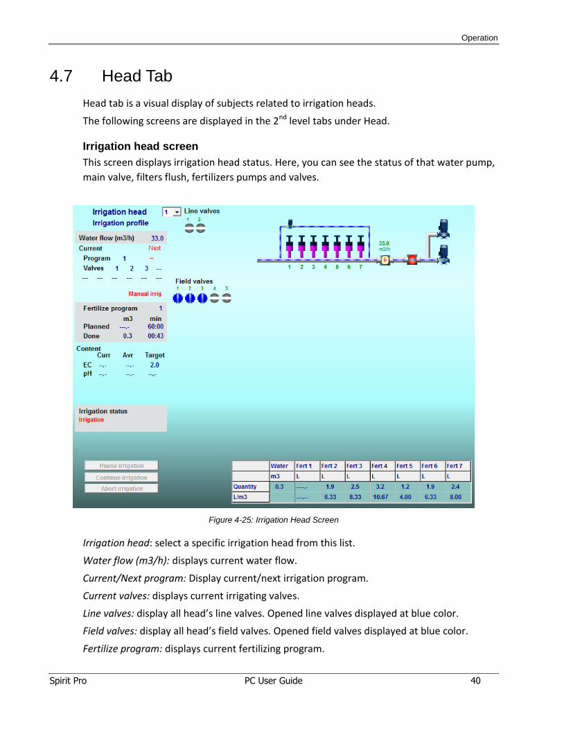
Irrigation head screen
This screen displays irrigation head status. Here, you can see the status of that water pump,
main valve, filters flush, fertilizers pumps and valves.
Figure 4-25: Irrigation Head Screen
Irrigation head: select a specific irrigation head from this list.
Water flow (m3/h): displays current water flow.
Current/Next program: Display current/next irrigation program.
Current valves: displays current irrigating valves.
Line valves: display all head’s line valves. Opened line valves displayed at blue color.
Field valves: display all head’s field valves. Opened field valves displayed at blue color.
Fertilize program: displays current fertilizing program.
Operation
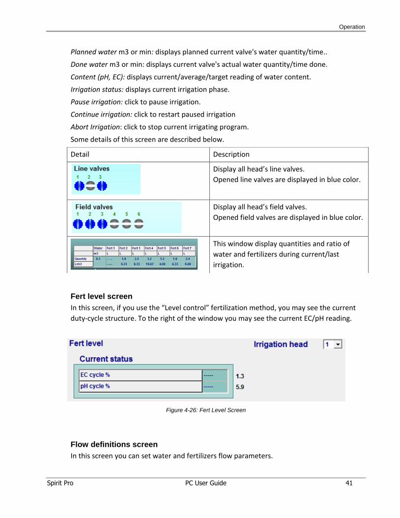
Spirit Pro PC User Guide 41
Planned water m3 or min: displays planned current valve's water quantity/time..
Done water m3 or min: displays current valve's actual water quantity/time done.
Content (pH, EC): displays current/average/target reading of water content.
Irrigation status: displays current irrigation phase.
Pause irrigation: click to pause irrigation.
Continue irrigation: click to restart paused irrigation
Abort Irrigation: click to stop current irrigating program.
Some details of this screen are described below.
Fert level screen
In this screen, if you use the “Level control” fertilization method, you may see the current
duty-cycle structure. To the right of the window you may see the current EC/pH reading.
Figure 4-26: Fert Level Screen
Flow definitions screen
In this screen you can set water and fertilizers flow parameters.
Detail Description
Display all head’s line valves.
Opened line valves are displayed in blue color.
Display all head’s field valves.
Opened field valves are displayed in blue color.
This window display quantities and ratio of
water and fertilizers during current/last
irrigation.
Operation
Spirit Pro PC User Guide 42
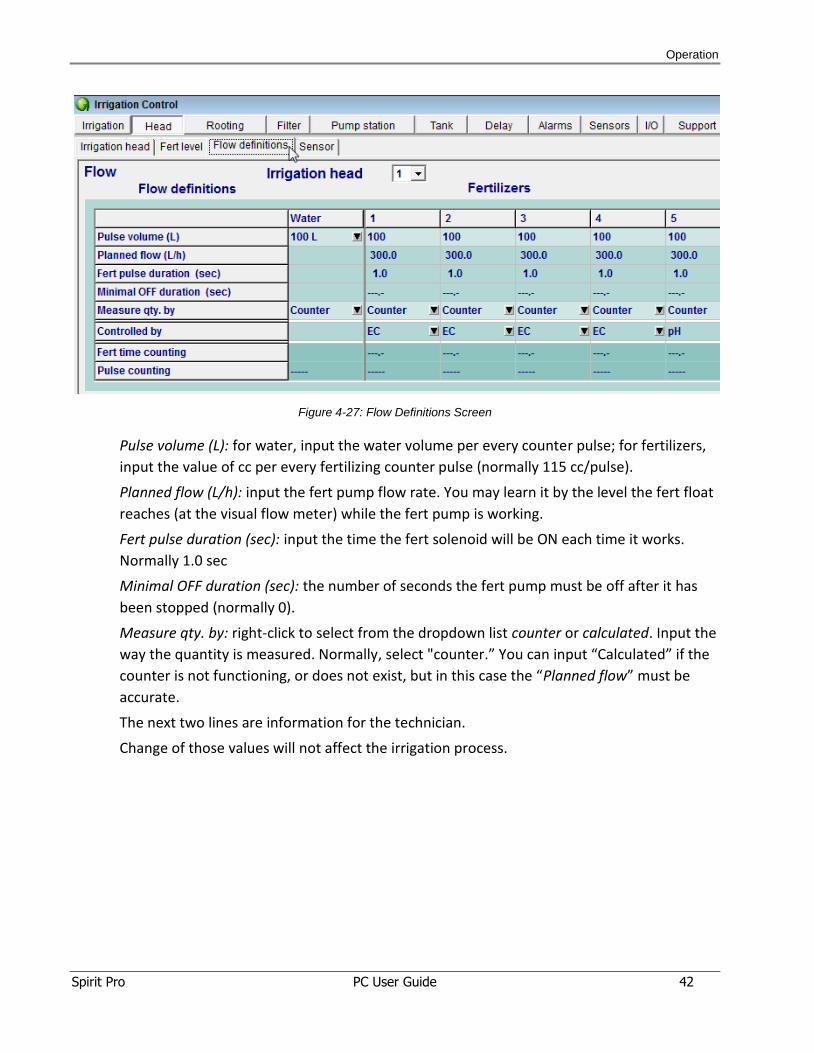
Figure 4-27: Flow Definitions Screen
Pulse volume (L): for water, input the water volume per every counter pulse; for fertilizers,
input the value of cc per every fertilizing counter pulse (normally 115 cc/pulse).
Planned flow (L/h): input the fert pump flow rate. You may learn it by the level the fert float
reaches (at the visual flow meter) while the fert pump is working.
Fert pulse duration (sec): input the time the fert solenoid will be ON each time it works.
Normally 1.0 sec
Minimal OFF duration (sec): the number of seconds the fert pump must be off after it has
been stopped (normally 0).
Measure qty. by: right-click to select from the dropdown list counter or calculated. Input the
way the quantity is measured. Normally, select "counter.” You can input “Calculated” if the
counter is not functioning, or does not exist, but in this case the “Planned flow” must be
accurate.
The next two lines are information for the technician.
Change of those values will not affect the irrigation process.
Operation
Spirit Pro PC User Guide 43
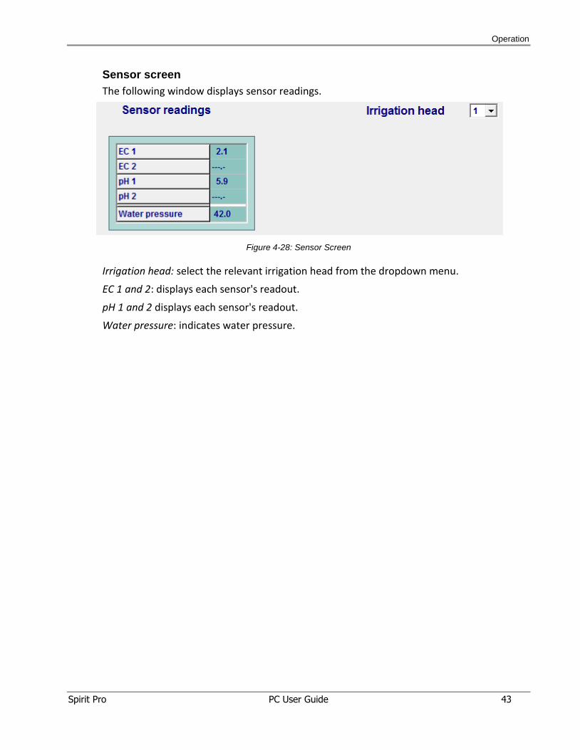
Sensor screen
The following window displays sensor readings.
Figure 4-28: Sensor Screen
Irrigation head: select the relevant irrigation head from the dropdown menu.
EC 1 and 2: displays each sensor's readout.
pH 1 and 2 displays each sensor's readout.
Water pressure: indicates water pressure.
Operation
Spirit Pro PC User Guide 44
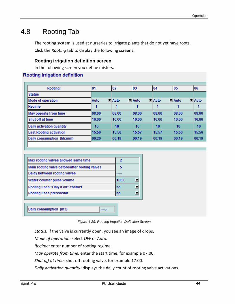
4.8 Rooting Tab
The rooting system is used at nurseries to irrigate plants that do not yet have roots.
Click the Rooting tab to display the following screens.
Rooting irrigation definition screen
In the following screen you define misters.
Figure 4-29: Rooting Irrigation Definition Screen
Status: if the valve is currently open, you see an image of drops.
Mode of operation: select OFF or Auto.
Regime: enter number of rooting regime.
May operate from time: enter the start time, for example 07:00.
Shut off at time: shut off rooting valve, for example 17:00.
Daily activation quantity: displays the daily count of rooting valve activations.
Operation
Spirit Pro PC User Guide 45
Last Rooting activation: displays the last time the rooting valve was open.
Daily consumption (hh:mm): displays daily water consumption by hours and minutes.
Max rooting valves allowed same time: enter maximum number of rooting valves open at
the same time.
Main rooting valve before/after rooting valves: enter open time of the main valve before
the first valve starts and after the last valve stops.
Delay between rooting valves: enter the delay time between activating valves, to allow
water pressure to build for the next valve.
Water counter pulse volume: open the dropdown list and select pulse volume: 1L, 10L, 100L,
1m3.
Rooting uses "Only if on" contact: open the dropdown list to define if the rooting system is
set to a contact. If "Yes,", the rooting system works only if the contact is ON.
Rooting uses pressostat: select Yes or No. If you select Yes, rooting irrigation is done only if
there is no signal of low-pressostat.
Daily consumption (m3): display the daily water consumption.
Operation
Spirit Pro PC User Guide 46
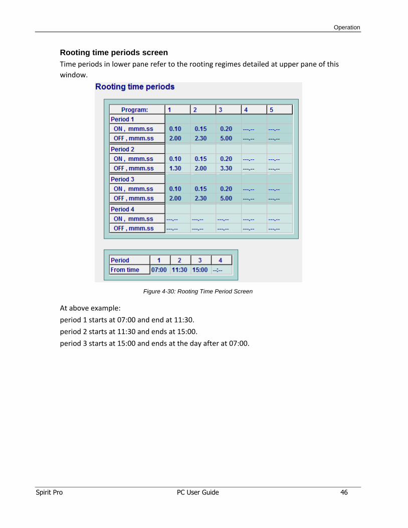
Rooting time periods screen
Time periods in lower pane refer to the rooting regimes detailed at upper pane of this
window.
Figure 4-30: Rooting Time Period Screen
At above example:
period 1 starts at 07:00 and end at 11:30.
period 2 starts at 11:30 and ends at 15:00.
period 3 starts at 15:00 and ends at the day after at 07:00.
Operation
Spirit Pro PC User Guide 47
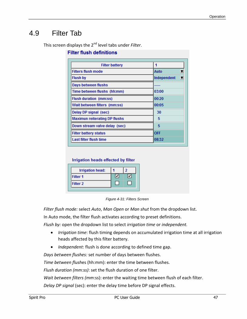
4.9 Filter Tab
This screen displays the 2nd level tabs under Filter.
Figure 4-31: Filters Screen
Filter flush mode: select Auto, Man Open or Man shut from the dropdown list.
In Auto mode, the filter flush activates according to preset definitions.
Flush by: open the dropdown list to select irrigation time or independent.
Irrigation time: flush timing depends on accumulated irrigation time at all irrigation
heads affected by this filter battery.
Independent: flush is done according to defined time gap.
Days between flushes: set number of days between flushes.
Time between flushes (hh:mm): enter the time between flushes.
Flush duration (mm:ss): set the flush duration of one filter.
Wait between filters (mm:ss): enter the waiting time between flush of each filter.
Delay DP signal (sec): enter the delay time before DP signal effects.
Operation
Spirit Pro PC User Guide 48
Maximum reiterating DP flushes: maximum number of repeating flushes by DP signal. After
this number of flushes, the filter ignores the DP signal.
Downstream valve delay (sec): Delay time after close of the downstream valve, to make
sure it is fully closed (optional).
Filter battery status: shows filter battery flush status as OFF or ON.
Last filter flush time: time of the last filter battery flush.
Irrigation heads affected by filter: select the irrigation heads that are affected by the filter
battery.
Operation
Spirit Pro PC User Guide 49
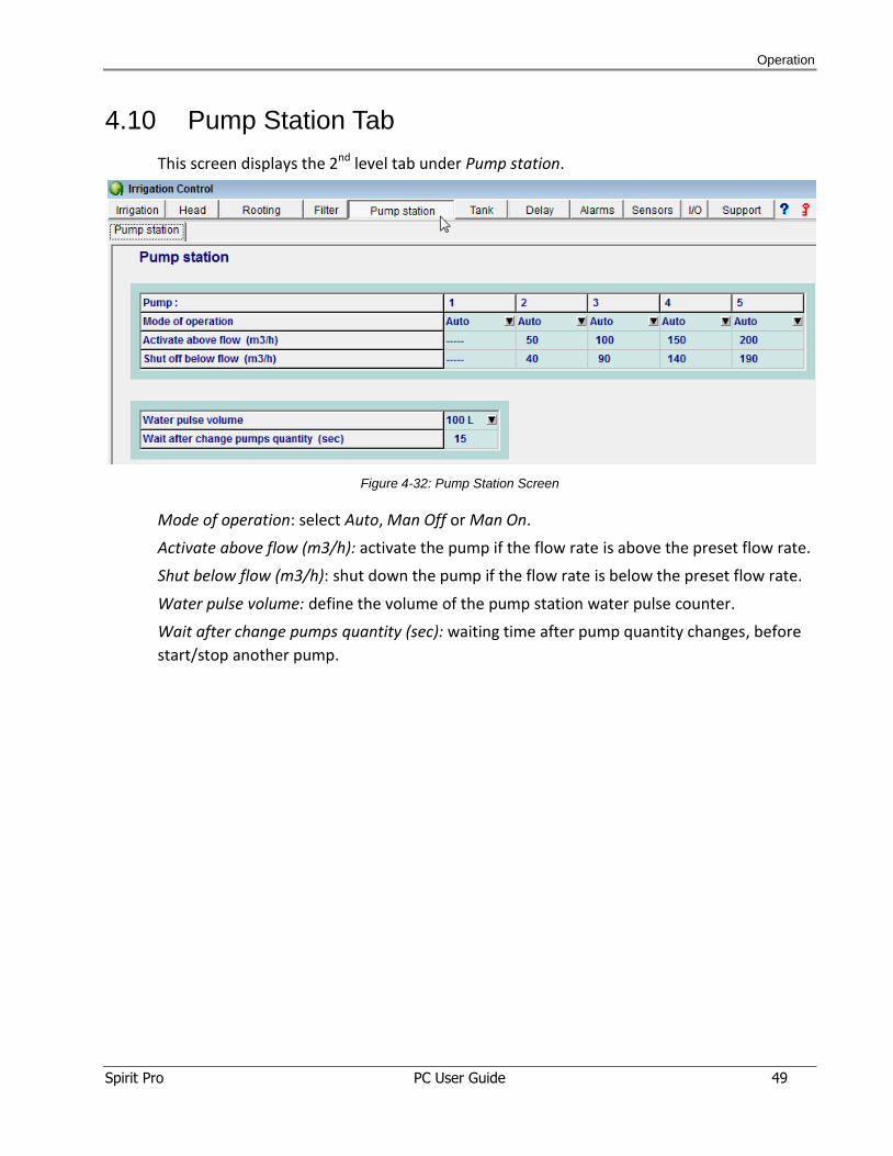
4.10 Pump Station Tab
This screen displays the 2nd level tab under Pump station.
Figure 4-32: Pump Station Screen
Mode of operation: select Auto, Man Off or Man On.
Activate above flow (m3/h): activate the pump if the flow rate is above the preset flow rate.
Shut below flow (m3/h): shut down the pump if the flow rate is below the preset flow rate.
Water pulse volume: define the volume of the pump station water pulse counter.
Wait after change pumps quantity (sec): waiting time after pump quantity changes, before
start/stop another pump.
Operation
Spirit Pro PC User Guide 50
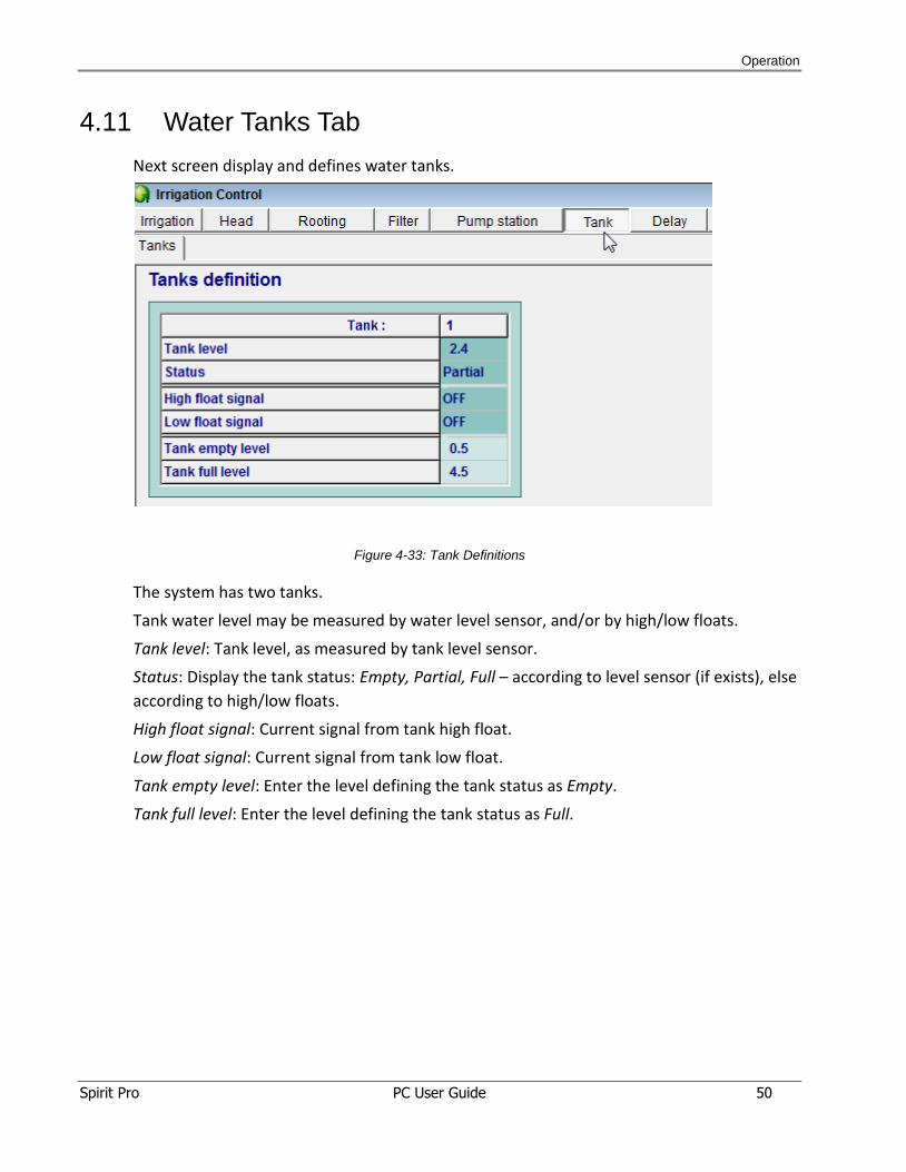
4.11 Water Tanks Tab
Next screen display and defines water tanks.
Figure 4-33: Tank Definitions
The system has two tanks.
Tank water level may be measured by water level sensor, and/or by high/low floats.
Tank level: Tank level, as measured by tank level sensor.
Status: Display the tank status: Empty, Partial, Full – according to level sensor (if exists), else
according to high/low floats.
High float signal: Current signal from tank high float.
Low float signal: Current signal from tank low float.
Tank empty level: Enter the level defining the tank status as Empty.
Tank full level: Enter the level defining the tank status as Full.
Operation
Spirit Pro PC User Guide 51
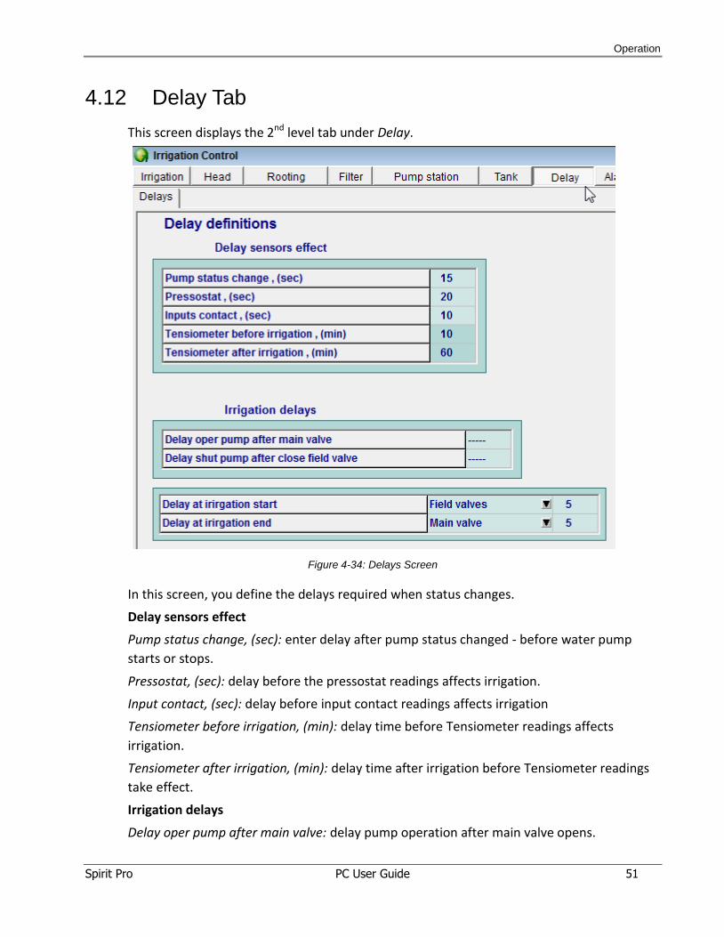
4.12 Delay Tab
This screen displays the 2nd level tab under Delay.
Figure 4-34: Delays Screen
In this screen, you define the delays required when status changes.
Delay sensors effect
Pump status change, (sec): enter delay after pump status changed - before water pump
starts or stops.
Pressostat, (sec): delay before the pressostat readings affects irrigation.
Input contact, (sec): delay before input contact readings affects irrigation
Tensiometer before irrigation, (min): delay time before Tensiometer readings affects
irrigation.
Tensiometer after irrigation, (min): delay time after irrigation before Tensiometer readings
take effect.
Irrigation delays
Delay oper pump after main valve: delay pump operation after main valve opens.
Operation
Spirit Pro PC User Guide 52
Delay shut pump after close field valve: delay time to shut pump after last field valve closes.
Delay at irrigation start: delay a device at irrigation start. Open the dropdown list and select
the device to delay.
Delay at irrigation end: delay a device at irrigation end. Open the dropdown list and select
the device to delay.
Operation
Spirit Pro PC User Guide 53
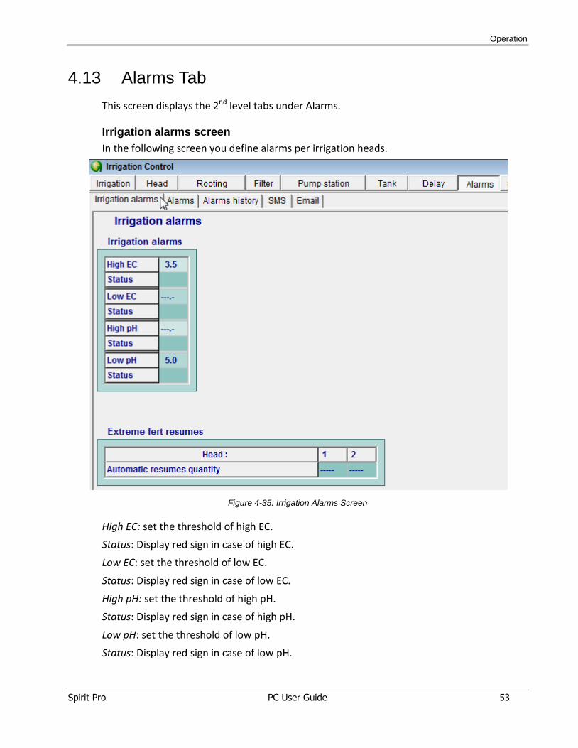
4.13 Alarms Tab
This screen displays the 2nd level tabs under Alarms.
Irrigation alarms screen
In the following screen you define alarms per irrigation heads.
Figure 4-35: Irrigation Alarms Screen
High EC: set the threshold of high EC.
Status: Display red sign in case of high EC.
Low EC: set the threshold of low EC.
Status: Display red sign in case of low EC.
High pH: set the threshold of high pH.
Status: Display red sign in case of high pH.
Low pH: set the threshold of low pH.
Status: Display red sign in case of low pH.
Operation
Spirit Pro PC User Guide 54
Extreme fert resumes
Automatic resumes quantity: number of times fertilization resumes automatically after an
extreme fert level event at a head.
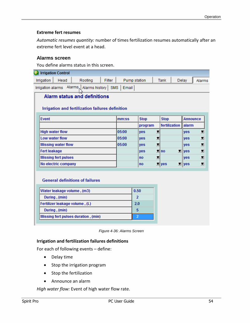
Alarms screen
You define alarms status in this screen.
Figure 4-36: Alarms Screen
Irrigation and fertilization failures definitions
For each of following events – define:
Delay time
Stop the irrigation program
Stop the fertilization
Announce an alarm
High water flow: Event of high water flow rate.
Operation
Spirit Pro PC User Guide 55
Low water flow: Event of low water flow rate..
Missing water flow: Event of no water pulses.
Fert leakage: Event of fert leakage.
Missing fert pulses: Event of missing fert pulses during fertilization.
No electric company: Event of “No electric company” signal.
General definitions of failures
Water leakage volume, (m3) during, (min): set the volume of the water leakage during the
set time.
Fertilizer leakage volume, (L) during, (min): set the volume of the fertilizer leakage (while no
fertilization expected) during the set time, to trigger an event.
Missing fert pulses duration, (min): set the waiting time of for fert pulse, to trigger “Missing
fert pulses” event.
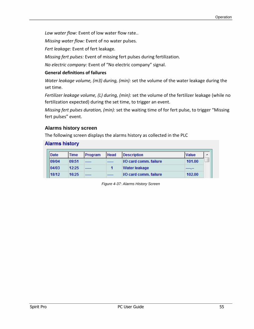
Alarms history screen
The following screen displays the alarms history as collected in the PLC
Figure 4-37: Alarms History Screen
Operation
Spirit Pro PC User Guide 56
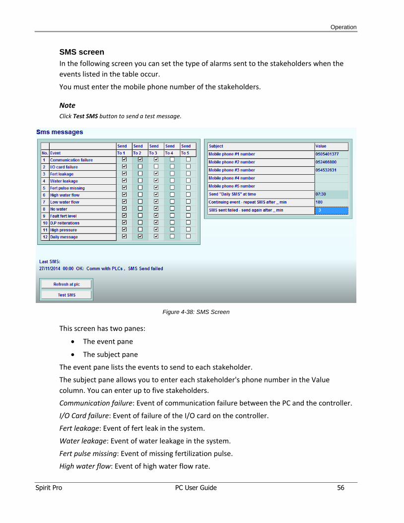
SMS screen
In the following screen you can set the type of alarms sent to the stakeholders when the
events listed in the table occur.
You must enter the mobile phone number of the stakeholders.
Note
Click Test SMS button to send a test message.
Figure 4-38: SMS Screen
This screen has two panes:
The event pane
The subject pane
The event pane lists the events to send to each stakeholder.
The subject pane allows you to enter each stakeholder's phone number in the Value
column. You can enter up to five stakeholders.
Communication failure: Event of communication failure between the PC and the controller.
I/O Card failure: Event of failure of the I/O card on the controller.
Fert leakage: Event of fert leak in the system.
Water leakage: Event of water leakage in the system.
Fert pulse missing: Event of missing fertilization pulse.
High water flow: Event of high water flow rate.
Operation
Spirit Pro PC User Guide 57
Low water flow: Event of low water flow rate.
No water: Event of no water from the main inlet or reservoir.
Fault fert level: Event of extreme fert level.
PD reiterations: Event of too many “Filter flush by DP” reiterations.
High pressure: Event of too high water pressure.
Daily message: Send a “Hello from GreenLine” message every day, to show that SMS system
is active.
Operation
Spirit Pro PC User Guide 58
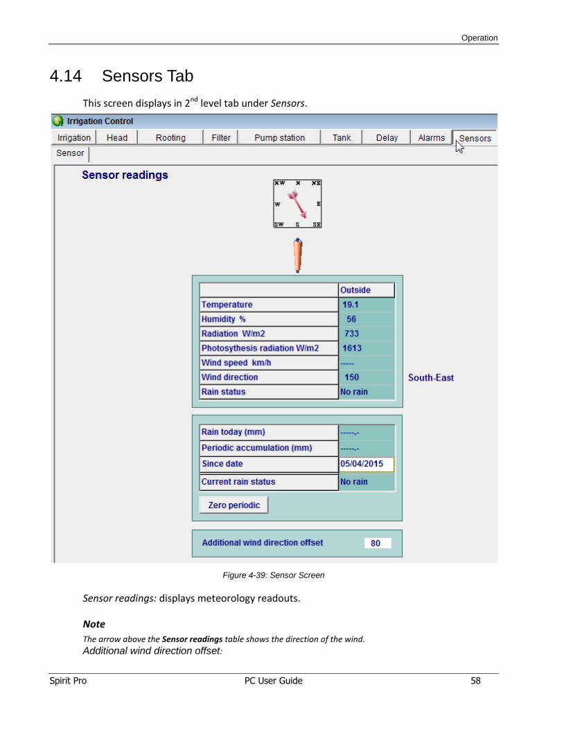
4.14 Sensors Tab
This screen displays in 2nd level tab under Sensors.
Figure 4-39: Sensor Screen
Sensor readings: displays meteorology readouts.
Note
The arrow above the Sensor readings table shows the direction of the wind.
Additional wind direction offset:
Operation
Spirit Pro PC User Guide 59
Fixes deviation between real wind direction – to the PC/PLC displayed wind direction:
Enter number degrees to be added to wind direction reading in order to compensate
deviation of the wind direction sensor.
The number is always added, not subtracted!
Note: Before change - first zero this number, and wait 20 seconds for new readings.
Examples:
a) The physical wind direction is bigger than PC displays:
If the physical wind blows from 270, and the PC displays 100, then write here 170 (to
bring the 100 to be 270).
The calculation here: 270 – 100 = 170.
b) The physical wind direction is less than then PC display:
If the physical wind blows from 30, and the PC displays 100, then write here 290 (to
bring the 100 to be 30).
The calculation here: 360 – 100 + 30 = 290.
Operation
Spirit Pro PC User Guide 60
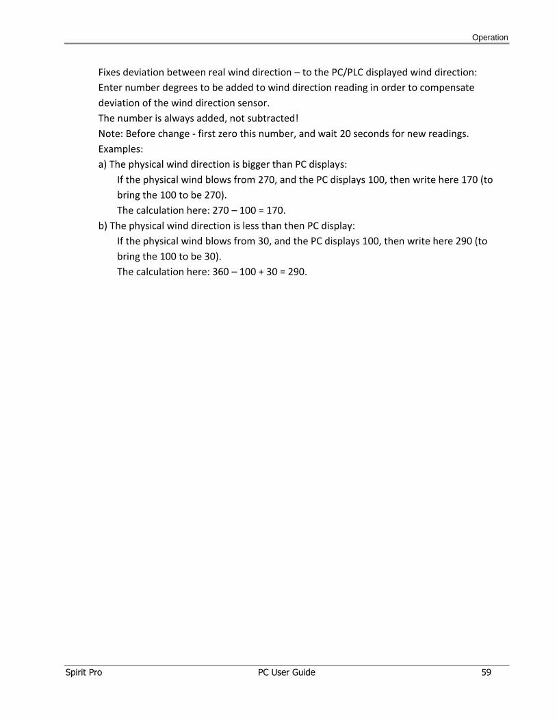
4.15 I/O Tab
The I/O tab displays 3 tabs on the 2nd level
Digital inputs
Analog inputs
Outputs
Figure 4-40: Outputs Screen
This screen displays outputs connected to the card by Output number, Subject, ID of the
subject, Output type, Output type ID.
Operation
Spirit Pro PC User Guide 61
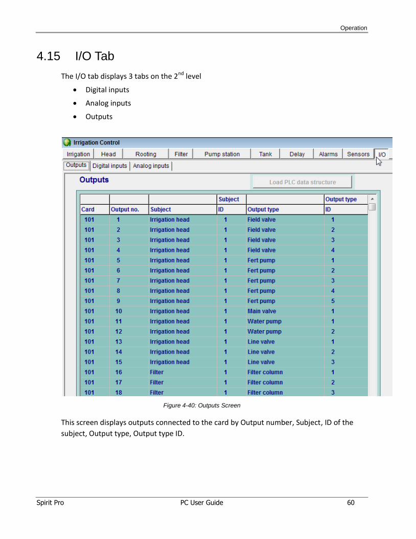
Figure 4-41: Digital Input Screen
This screen displays the digital inputs connected to the card by Input number, Subject ID of
the subject, Input type, Input type ID and Input for signal (ON/OFF).
Figure 4-42: Analog Input Screen
This screen displays the analog inputs connected to the card by Input number, Subject ID of
the subject, Input type, Input type ID, low scale, high scale, current reading.
Operation
Spirit Pro PC User Guide 62
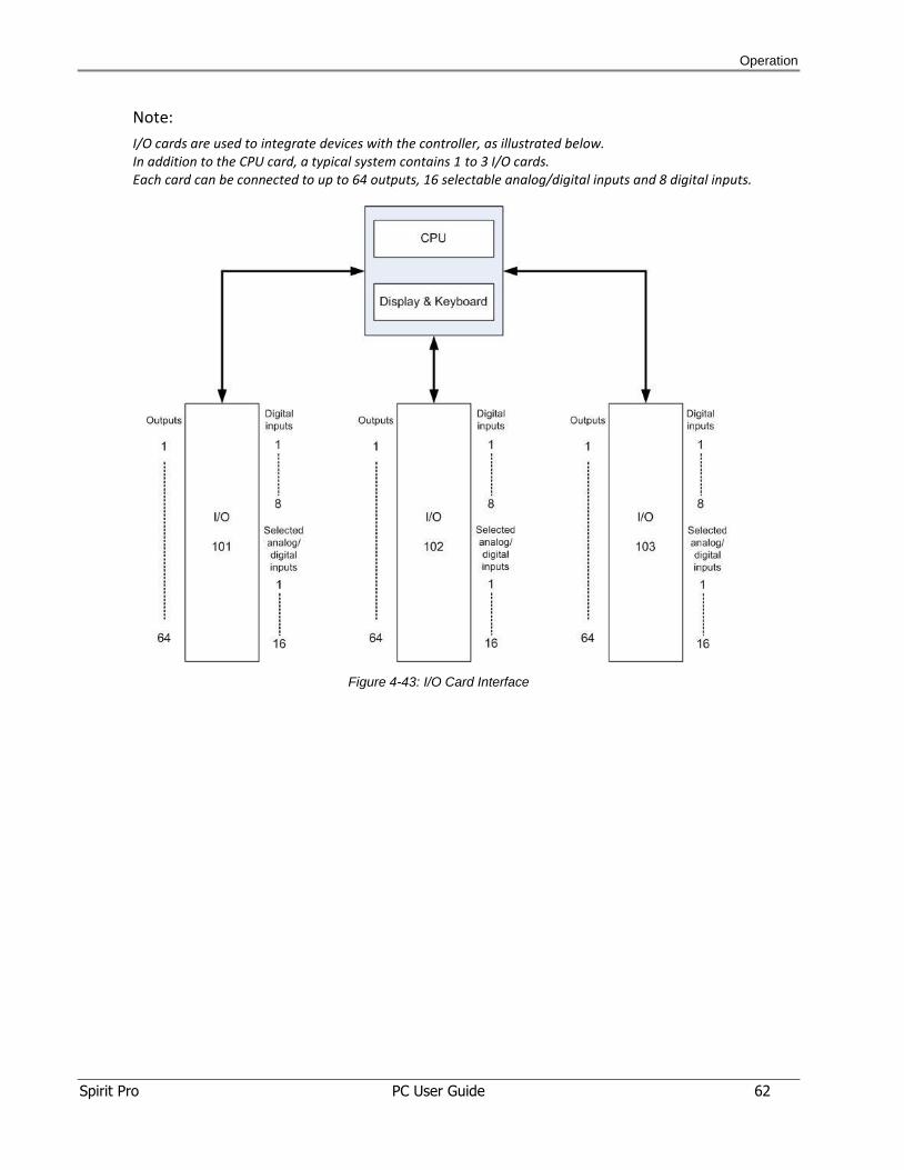
Note:
I/O cards are used to integrate devices with the controller, as illustrated below. In addition to the CPU card, a typical system contains 1 to 3 I/O cards. Each card can be connected to up to 64 outputs, 16 selectable analog/digital inputs and 8 digital inputs.
Figure 4-43: I/O Card Interface
Operation
Spirit Pro PC User Guide 63
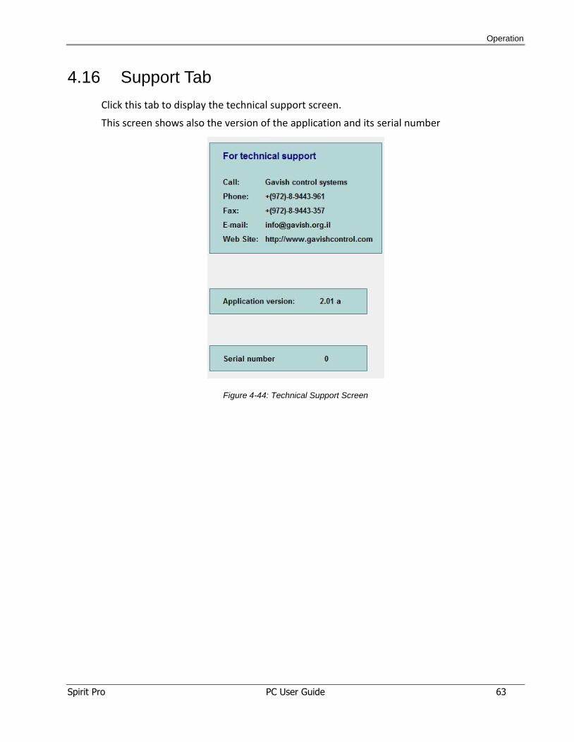
4.16 Support Tab
Click this tab to display the technical support screen.
This screen shows also the version of the application and its serial number
Figure 4-44: Technical Support Screen
Operation
Spirit Pro PC User Guide 64
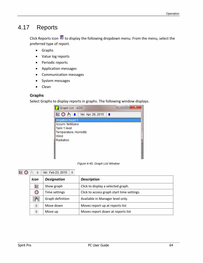
4.17 Reports
Click Reports icon to display the following dropdown menu. From the menu, select the
preferred type of report.
Graphs
Value log reports
Periodic reports
Application messages
Communication messages
System messages
Clean
Graphs
Select Graphs to display reports in graphs. The following window displays.
Figure 4-45: Graph List Window
Icon Designation Description
Show graph Click to display a selected graph.
Time settings Click to access graph start time settings.
Graph definition Available in Manager level only.
Move down Moves report up at reports list
Move up Moves report down at reports list
Operation
Spirit Pro PC User Guide 65
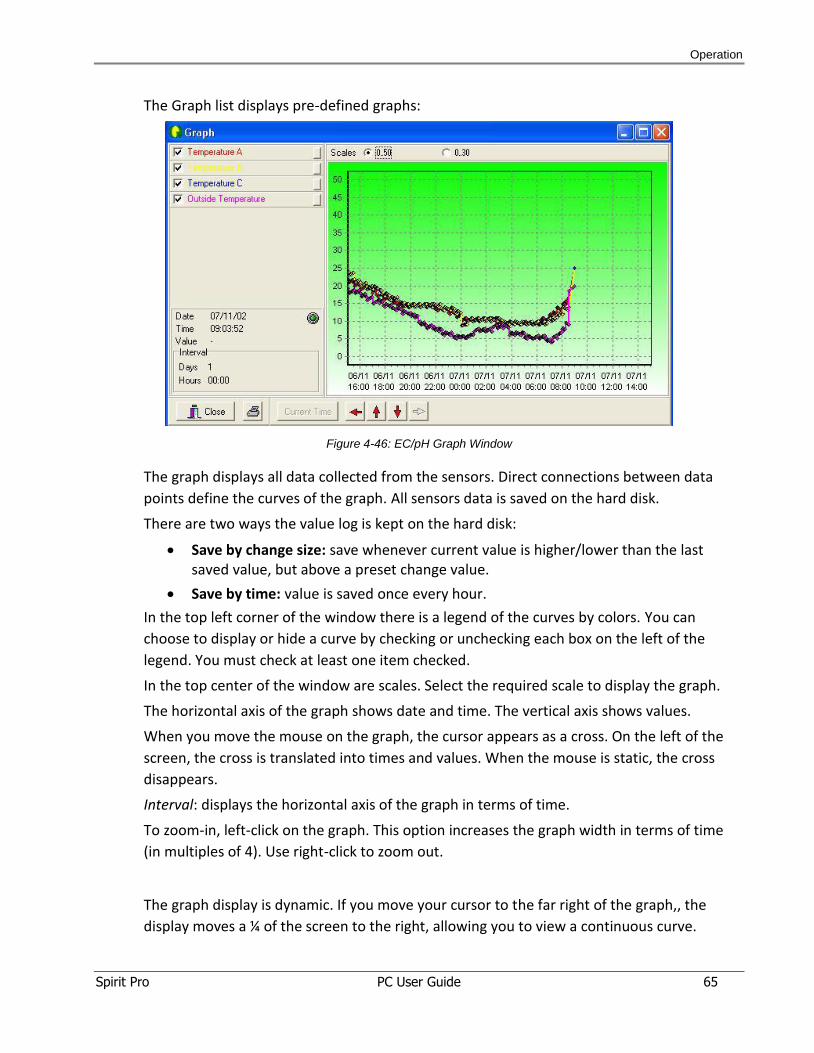
The Graph list displays pre-defined graphs:
Figure 4-46: EC/pH Graph Window
The graph displays all data collected from the sensors. Direct connections between data
points define the curves of the graph. All sensors data is saved on the hard disk.
There are two ways the value log is kept on the hard disk:
Save by change size: save whenever current value is higher/lower than the last saved value, but above a preset change value.
Save by time: value is saved once every hour.
In the top left corner of the window there is a legend of the curves by colors. You can
choose to display or hide a curve by checking or unchecking each box on the left of the
legend. You must check at least one item checked.
In the top center of the window are scales. Select the required scale to display the graph.
The horizontal axis of the graph shows date and time. The vertical axis shows values.
When you move the mouse on the graph, the cursor appears as a cross. On the left of the
screen, the cross is translated into times and values. When the mouse is static, the cross
disappears.
Interval: displays the horizontal axis of the graph in terms of time.
To zoom-in, left-click on the graph. This option increases the graph width in terms of time
(in multiples of 4). Use right-click to zoom out.
The graph display is dynamic. If you move your cursor to the far right of the graph,, the
display moves a ¼ of the screen to the right, allowing you to view a continuous curve.
Operation
Spirit Pro PC User Guide 66
Click the Current Time button to include current time data in the graph. When the display
contains current time data, the green indicator on the left side blinks. Otherwise, the green
indicator is off and the Current Time button is enabled.
The arrows under the graph enable you to move the graph in different directions.
To print the displayed graph, click the printer icon at the bottom of the window.
Time settings
In Graph List window, click the Time Settings icon to access time settings:
Here you can set the graph's start date, start time and window width (interval). You can use
this option to view a graph from any time in the past.
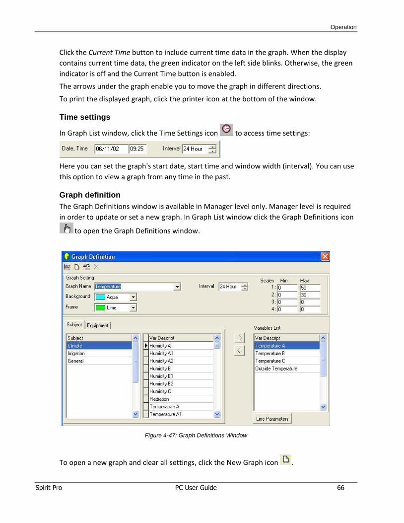
Graph definition
The Graph Definitions window is available in Manager level only. Manager level is required
in order to update or set a new graph. In Graph List window click the Graph Definitions icon
to open the Graph Definitions window.
Figure 4-47: Graph Definitions Window
To open a new graph and clear all settings, click the New Graph icon .
Operation
Spirit Pro PC User Guide 67
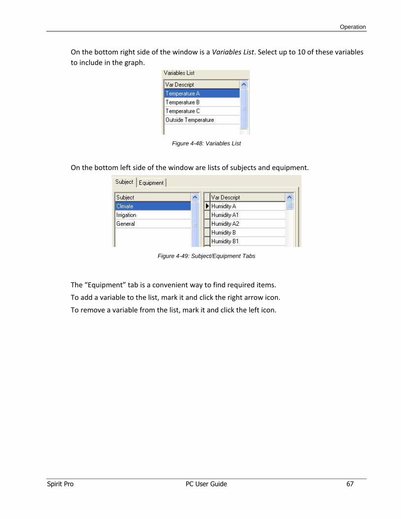
On the bottom right side of the window is a Variables List. Select up to 10 of these variables
to include in the graph.
Figure 4-48: Variables List
On the bottom left side of the window are lists of subjects and equipment.
Figure 4-49: Subject/Equipment Tabs
The “Equipment” tab is a convenient way to find required items.
To add a variable to the list, mark it and click the right arrow icon.
To remove a variable from the list, mark it and click the left icon.

Operation
Spirit Pro PC User Guide 68
You may define the line parameters for each selected variable in the graph.
Click Line Parameters button to open Line Parameters window and set the parameters of
the different curves in the graph.
Figure 4-50: Line Parameters Window
Graph Name: After defining all graph parameters, click the “Save” icon .
Then enter the name of the graph.
Background: set the graph's background color.
Frame: set the graph's frame color.
Interval: set the time interval for the horizontal axis (Y).
Values range: set the range of on the vertical axis (X). To display temperature readings, set it
between 10-50.
Color: select curve color.
Point Style: select style of points to display on the graph.
Line Width: select curve width (1 to 4).
Point Size: select point size (1 to 4).
Line Points Curve: useful for curves of continuous values, such as temperatures. Points are
connected with a continuous line.
Line Curve: displays a continuous line without points.
Line Stairs Curve: useful for curves of discreet values, such as "Irrigating valve number".
Area Stairs curve: display the area under the stairs curve.
To confirm the settings, click OK.
To delete a graph, click the Delete icon .
Operation
Spirit Pro PC User Guide 69
Note:
You can only delete user-defined graphs. You cannot delete graphs supplied by Gavish.
Value log reports
The values of the variables are being kept on the hard disk according to "change level" and
according to time change (normally every one hour).
In order to produce a report you have to set date and time range at the top of the window.
The available pre-prepared reports are listed on the left pane of the window. Mark the
required report and click on the "Show Report" icon. The "Full" report displays all logged
values.
At the bottom of the report you may view an information line presenting number of lines in
the report (updated only after clicking the "Show Report" icon).
Export to text file icon enables you to export the report to a text file, in order to transfer
data into other programs, such as Excel.
Send to printer icon sends the displayed report to the printer.
Select Value log reports from the Reports dropdown menu to display the following window.
Operation
Spirit Pro PC User Guide 70
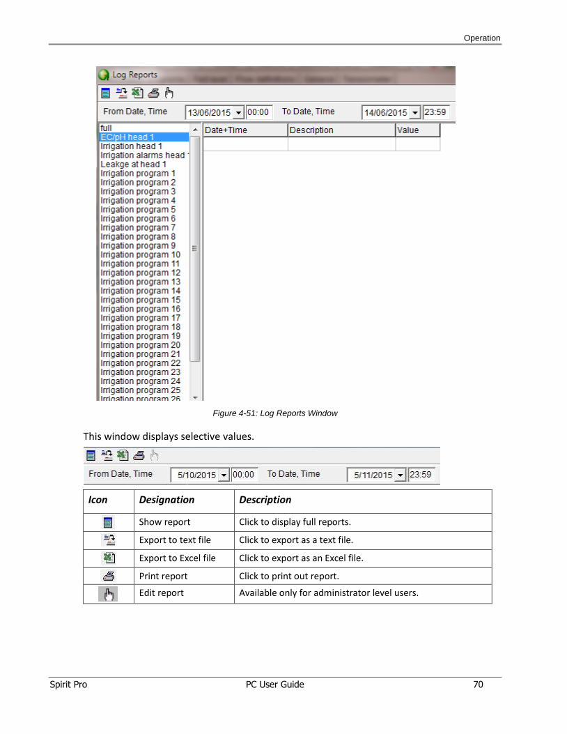
Figure 4-51: Log Reports Window
This window displays selective values.
Icon Designation Description
Show report Click to display full reports.
Export to text file Click to export as a text file.
Export to Excel file Click to export as an Excel file.
Print report Click to print out report.
Edit report Available only for administrator level users.
Operation
Spirit Pro PC User Guide 71
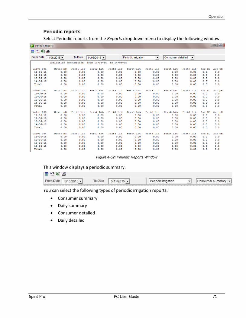
Periodic reports
Select Periodic reports from the Reports dropdown menu to display the following window.
Figure 4-52: Periodic Reports Window
This window displays a periodic summary.
You can select the following types of periodic irrigation reports:
Consumer summary
Daily summary
Consumer detailed
Daily detailed
Operation
Spirit Pro PC User Guide 72
Below is the Reports toolbar for:
System messages
Communication messages
Application messages
Icon Designation Description
Save and exit Click CTRL+W to save and exit.
Save Click CTRL+S to save the report.
Copy to find Click CTRL+E to copy to find.
Find first Click CTRL+F to show the first row.
Find next Click F3 to show the next row.
Go to line Click CTRL+G and set the row of interest.
Additional action menu Special tools for advanced user
Open with notepad Click to open with notepad
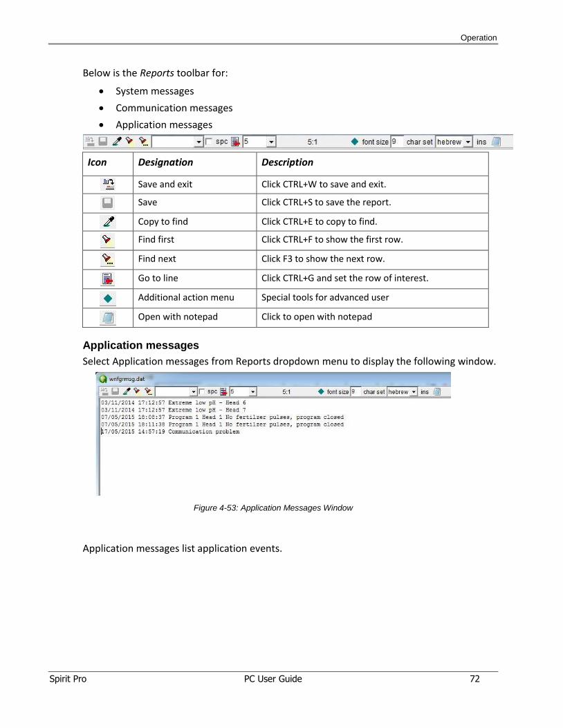
Application messages
Select Application messages from Reports dropdown menu to display the following window.
Figure 4-53: Application Messages Window
Application messages list application events.
Operation
Spirit Pro PC User Guide 73
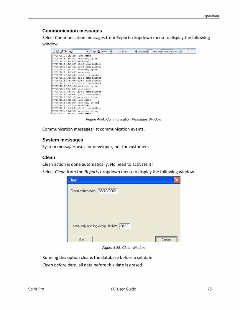
Communication messages
Select Communication messages from Reports dropdown menu to display the following
window.
Figure 4-54: Communication Messages Window
Communication messages list communication events.
System messages
System messages uses for developer, not for customers.
Clean
Clean action is done automatically. No need to activate it!
Select Clean from the Reports dropdown menu to display the following window.
Figure 4-55: Clean Window
Running this option cleans the database before a set date.
Clean before date: all data before this date is erased.
Operation
Spirit Pro PC User Guide 74
Leave only one log every HH:MM: logged data before the set date are cleaned except for
one log every HH:MM. For example, if you clean before 01/01/2015, but set the time to
00:60, you will delete all logs except for one log every 60 minutes.
Click Go! to perform the cleaning operation.
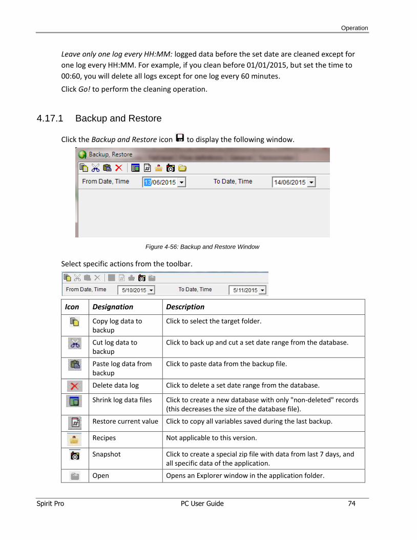
4.17.1 Backup and Restore
Click the Backup and Restore icon to display the following window.
Figure 4-56: Backup and Restore Window
Select specific actions from the toolbar.
Icon Designation Description
Copy log data to backup
Click to select the target folder.
Cut log data to backup
Click to back up and cut a set date range from the database.
Paste log data from backup
Click to paste data from the backup file.
Delete data log Click to delete a set date range from the database.
Shrink log data files Click to create a new database with only "non-deleted" records
(this decreases the size of the database file).
Restore current value Click to copy all variables saved during the last backup.
Recipes Not applicable to this version.
Snapshot Click to create a special zip file with data from last 7 days, and
all specific data of the application.
Open Opens an Explorer window in the application folder.
Operation
Spirit Pro PC User Guide 75
4.17.2 Communication
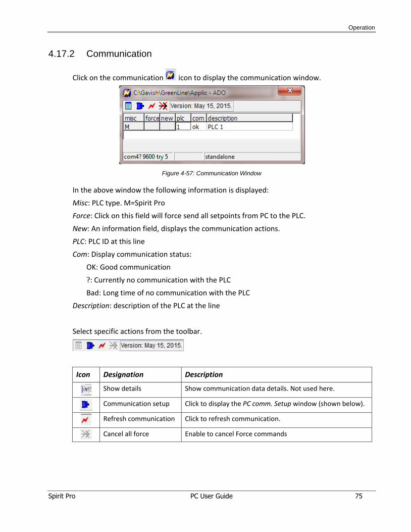
Click on the communication icon to display the communication window.
Figure 4-57: Communication Window
In the above window the following information is displayed:
Misc: PLC type. M=Spirit Pro
Force: Click on this field will force send all setpoints from PC to the PLC.
New: An information field, displays the communication actions.
PLC: PLC ID at this line
Com: Display communication status:
OK: Good communication
?: Currently no communication with the PLC
Bad: Long time of no communication with the PLC
Description: description of the PLC at the line
Select specific actions from the toolbar.
Icon Designation Description
Show details Show communication data details. Not used here.
Communication setup Click to display the PC comm. Setup window (shown below).
Refresh communication Click to refresh communication.
Cancel all force Enable to cancel Force commands
Operation
Spirit Pro PC User Guide 76
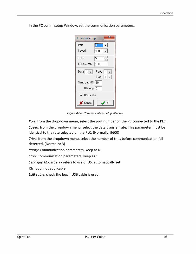
In the PC comm setup Window, set the communication parameters.
Figure 4-58: Communication Setup Window
Port: from the dropdown menu, select the port number on the PC connected to the PLC.
Speed: from the dropdown menu, select the data transfer rate. This parameter must be
identical to the rate selected on the PLC. (Normally: 9600)
Tries: from the dropdown menu, select the number of tries before communication fail
detected. (Normally: 3)
Parity: Communication parameters, keep as N.
Stop: Communication parameters, keep as 1.
Send gap MS: a delay refers to use of US, automatically set.
Rts loop: not applicable .
USB cable: check the box if USB cable is used.
Troubleshooting
Spirit Pro PC User Guide 77
5 TTrroouubblleesshhoooottiinngg
Troubleshooting
Spirit Pro PC User Guide 78
5.1 Communication Failures Troubleshooting
Perform the following steps to troubleshoot communication failures.
Action sequence for:
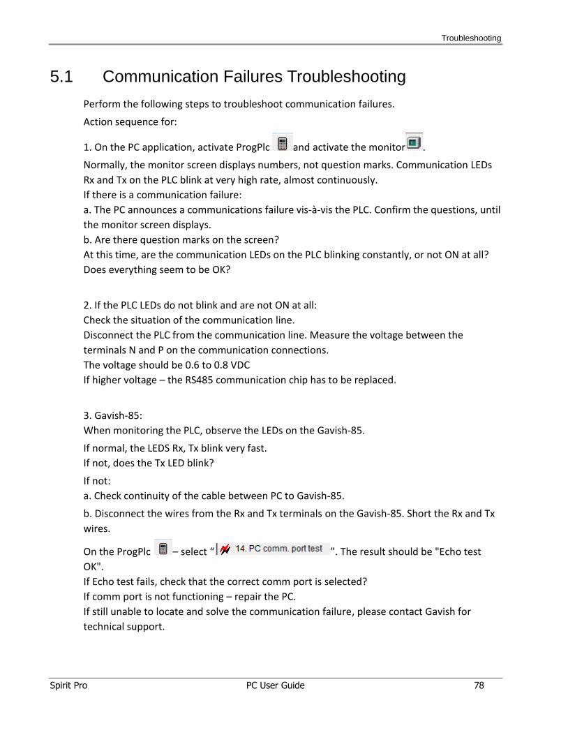
1. On the PC application, activate ProgPlc and activate the monitor .
Normally, the monitor screen displays numbers, not question marks. Communication LEDs
Rx and Tx on the PLC blink at very high rate, almost continuously.
If there is a communication failure:
a. The PC announces a communications failure vis-à-vis the PLC. Confirm the questions, until
the monitor screen displays.
b. Are there question marks on the screen?
At this time, are the communication LEDs on the PLC blinking constantly, or not ON at all?
Does everything seem to be OK?
2. If the PLC LEDs do not blink and are not ON at all:
Check the situation of the communication line.
Disconnect the PLC from the communication line. Measure the voltage between the
terminals N and P on the communication connections.
The voltage should be 0.6 to 0.8 VDC
If higher voltage – the RS485 communication chip has to be replaced.
3. Gavish-85:
When monitoring the PLC, observe the LEDs on the Gavish-85.
If normal, the LEDS Rx, Tx blink very fast.
If not, does the Tx LED blink?
If not:
a. Check continuity of the cable between PC to Gavish-85.
b. Disconnect the wires from the Rx and Tx terminals on the Gavish-85. Short the Rx and Tx
wires.
On the ProgPlc – select “ ”. The result should be "Echo test
OK".
If Echo test fails, check that the correct comm port is selected?
If comm port is not functioning – repair the PC.
If still unable to locate and solve the communication failure, please contact Gavish for
technical support.

Appendix - GreenLine View-PC Network
Spirit Pro PC User Guide 79
AAppppeennddiixx -- GGrreeeennLLiinnee VViieeww--PPCC NNeettwwoorrkk
Appendix - GreenLine View-PC Network
Spirit Pro PC User Guide 80
6.1 General
The network allows the PC to communicate with the programmable logic controller (PLC).
You can also connect more PCs to the main GreenLine PC, to share data, such as screens,
reports and graphs.
Simultaneous operation of multiple PCs with GreenLine does not interrupt the operation of
the main PC in the PLCs network.
6.2 Deployment
GreenLine View-PC system includes a main PC and view PCs connected through a local area
network (LAN).
The main PC must be powered on continuously to collect data through the RS-485 network
from the PLC. You can connect/disconnect view PCs to the Main PC at any time.
Data exchange between the main PC and view PCs is via client-server protocol.
You can connect the main PC and view PCs to a common LAN workgroup with an Ethernet
cable plugged into a hub or a switch. If there is only one view PC, you can connect it to the
main PC via a peer-to-peer cross-wired network cable. This situation does not require a LAN
and hub or switch.
LAN wiring is limited to about 100 – 150 meters. For longer distances, you must install fiber
optic cables and terminals.
Typical LAN deployments are illustrated below.
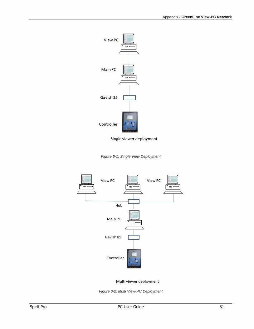
Appendix - GreenLine View-PC Network
Spirit Pro PC User Guide 81
Figure 6-1: Single View Deployment
Figure 6-2: Multi View-PC Deployment
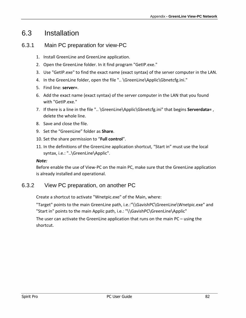
Appendix - GreenLine View-PC Network
Spirit Pro PC User Guide 82
6.3 Installation
6.3.1 Main PC preparation for view-PC
1. Install GreenLine and GreenLine application.
2. Open the GreenLine folder. In it find program "GetIP.exe."
3. Use "GetIP.exe" to find the exact name (exact syntax) of the server computer in the LAN.
4. In the GreenLine folder, open the file ".. \GreenLine\Applic\Gbnetcfg.ini."
5. Find line: server=.
6. Add the exact name (exact syntax) of the server computer in the LAN that you found
with "GetIP.exe."
7. If there is a line in the file ".. \GreenLine\Applic\Gbnetcfg.ini" that begins Serverdata= ,
delete the whole line.
8. Save and close the file.
9. Set the “GreenLine” folder as Share.
10. Set the share permission to “Full control”.
11. In the definitions of the GreenLine application shortcut, “Start in” must use the local
syntax, i.e.: "..\GreenLine\Applic".
Note:
Before enable the use of View-PC on the main PC, make sure that the GreenLine application
is already installed and operational.
6.3.2 View PC preparation, on another PC
Create a shortcut to activate "Wnetpic.exe" of the Main, where:
"Target" points to the main GreenLine path, i.e.:"\\GavishPC\GreenLine\Wnetpic.exe" and
"Start in" points to the main Applic path, i.e.: "\\GavishPC\GreenLine\Applic"
The user can activate the GreenLine application that runs on the main PC – using the
shortcut.

GAVISH CONTROL SYSTEMS LTD.
Givat Brenner, 60948, Israel. Tel: +972-8-9443961 Fax: +972-8-9443357
E-mail: [email protected] Website: http://www.gavishcontrol.com