Embed Size (px)
Citation preview
SERVICE MANUAL
CONTENTS1. TECHNICAL CHANGES ····································22. PART NAMES AND FUNCTIONS······················33. SPECIFICATION·················································54. NOISE CRITERIA CURVES·······························65. OUTLINES AND DIMENSIONS ·························76. WIRING DIAGRAM ············································87. REFRIGERANT SYSTEM DIAGRAM ················88. SERVICE FUNCTIONS ······································99. TROUBLESHOOTING······································10
10. DISASSEMBLY INSTRUCTIONS·····················2411. PARTS LIST······················································2712. OPTIONAL PARTS···········································30
Wireless typeModels
MSZ-GA22VA - (WH)
MSZ-GA25VA - (WH)
MSZ-GA35VA - (WH)E1
E1
E1
No. OB378
SPLIT-TYPE, HEAT PUMP AIR CONDITIONERS
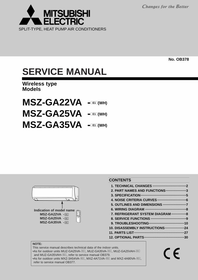
Indication of model nameMSZ-GA22VA -MSZ-GA25VA -MSZ-GA35VA - E1
E1
E1
NOTE:This service manual describes technical data of the indoor units.•As for outdoor units MUZ-GA25VA- , MUZ-GA35VA- , MUZ-GA25VAH-and MUZ-GA35VAH- , refer to service manual OB379.
•As for outdoor units MXZ-3A54VA- , MXZ-4A71VA- and MXZ-4A80VA- ,refer to service manual OB377.
E1E1E1
E1
E1E1E1
OB378_--1qxp 05.1.17 12:55 Page 1
2
1 TECHNICAL CHANGES
MSZ-A09YV - ➔ MSZ-GA22VA -MSZ-A09YV - ➔ MSZ-GA25VA -MSZ-A12YV - ➔ MSZ-GA35VA - E1E1
E1E1
E1E1
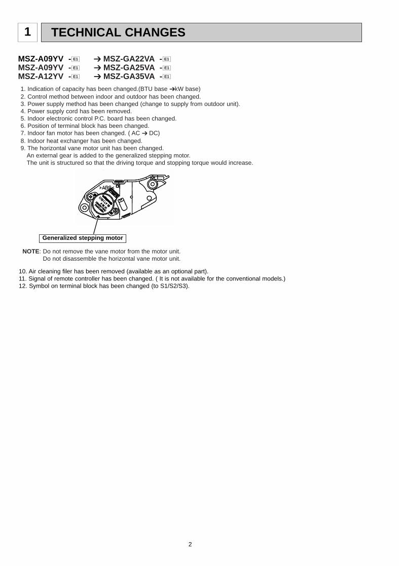
1. Indication of capacity has been changed.(BTU base ➔kW base)2. Control method between indoor and outdoor has been changed.3. Power supply method has been changed (change to supply from outdoor unit).4. Power supply cord has been removed.5. Indoor electronic control P.C. board has been changed.6. Position of terminal block has been changed.7. Indoor fan motor has been changed. ( AC ➔ DC)8. Indoor heat exchanger has been changed.9. The horizontal vane motor unit has been changed.
An external gear is added to the generalized stepping motor. The unit is structured so that the driving torque and stopping torque would increase.
NOTE: Do not remove the vane motor from the motor unit.Do not disassemble the horizontal vane motor unit.
Generalized stepping motor
10. Air cleaning filer has been removed (available as an optional part).11. Signal of remote controller has been changed. ( It is not available for the conventional models.)12. Symbol on terminal block has been changed (to S1/S2/S3).
OB378_--1qxp 05.1.17 12:55 Page 2
3
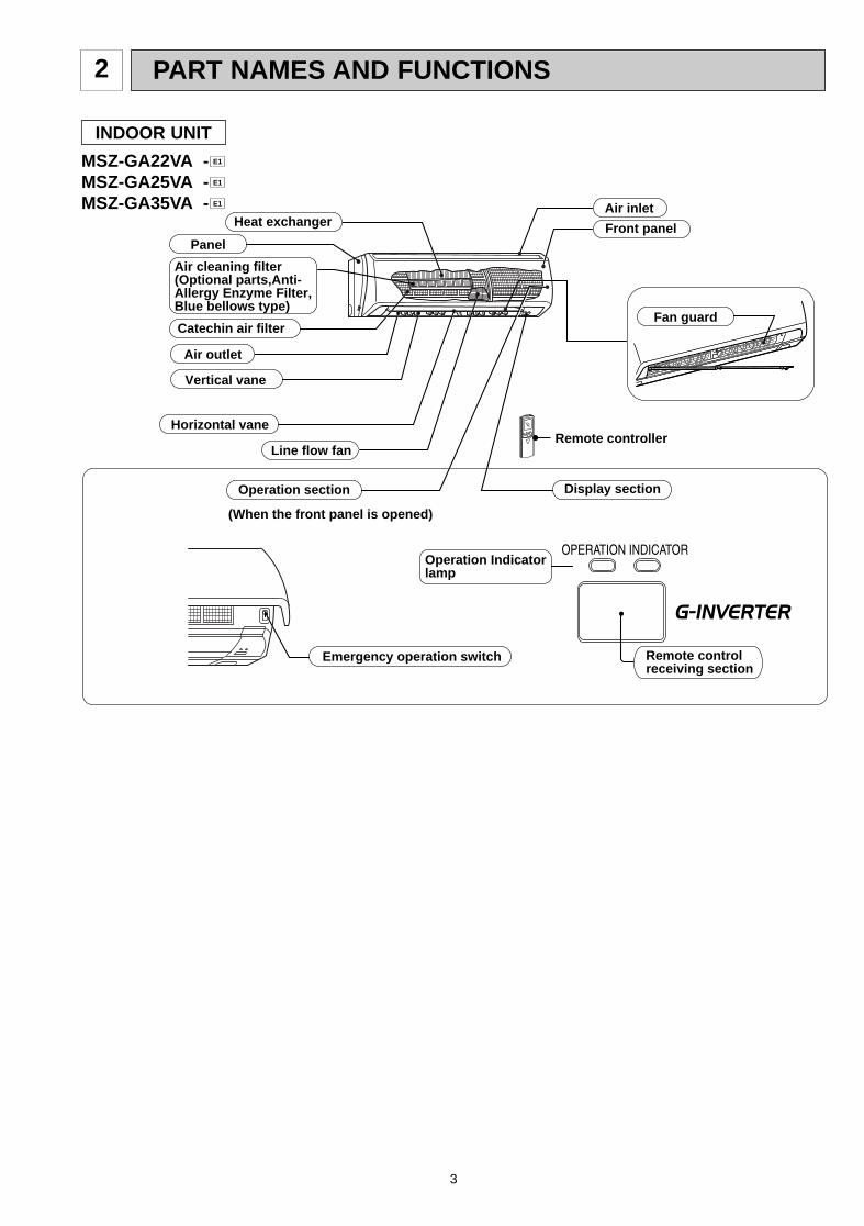
PART NAMES AND FUNCTIONS2
INDOOR UNIT
MSZ-GA22VA -MSZ-GA25VA -MSZ-GA35VA - E1
E1
E1
Line flow fan
Air outlet
Vertical vane
Air inlet
Display section
Front panelPanel
Heat exchanger
Horizontal vane
Operation section
(When the front panel is opened)
Remote controller
Remote controlreceiving section
Catechin air filter
Air cleaning filter(Optional parts,Anti-Allergy Enzyme Filter,Blue bellows type)
Emergency operation switch
Fan guard
Operation Indicatorlamp
OB378_--1qxp 05.1.17 12:55 Page 3
4
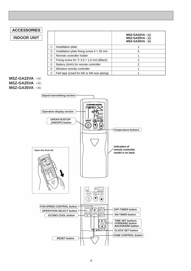
ACCESSORIES
1
2
3
4
5
6
7
Installation plate
Installation plate fixing screw 4 o 25 mm
Remote controller holder
Fixing screw for 3 3.5 o 1.6 mm (Black)
Battery (AAA) for remote controller
Wireless remote controller
Felt tape (Used for left or left-rear piping)
MSZ-GA22VA - E1
MSZ-GA25VA - E1
1
5
1
2
2
1
1
MSZ-GA35VA - E1
INDOOR UNIT
ON-TIMER button
CLOCK SET button
TIME SET buttonsFORWARD buttonBACKWARD button
OFF-TIMER button
(This diagram shows an overall view.)
Open the front lid.
RESET buttonVANE CONTROL button
Signal transmitting section
Operation display section
Temperature buttons
OPERATE/STOP (ON/OFF) button
FAN SPEED CONTROL button
OPERATION SELECT button
ECONO COOL button
Indication of remote controllermodel is on back
MSZ-GA22VA -MSZ-GA25VA -MSZ-GA35VA - E1
E1
E1
OB378_--1qxp 05.1.17 12:55 Page 4
5
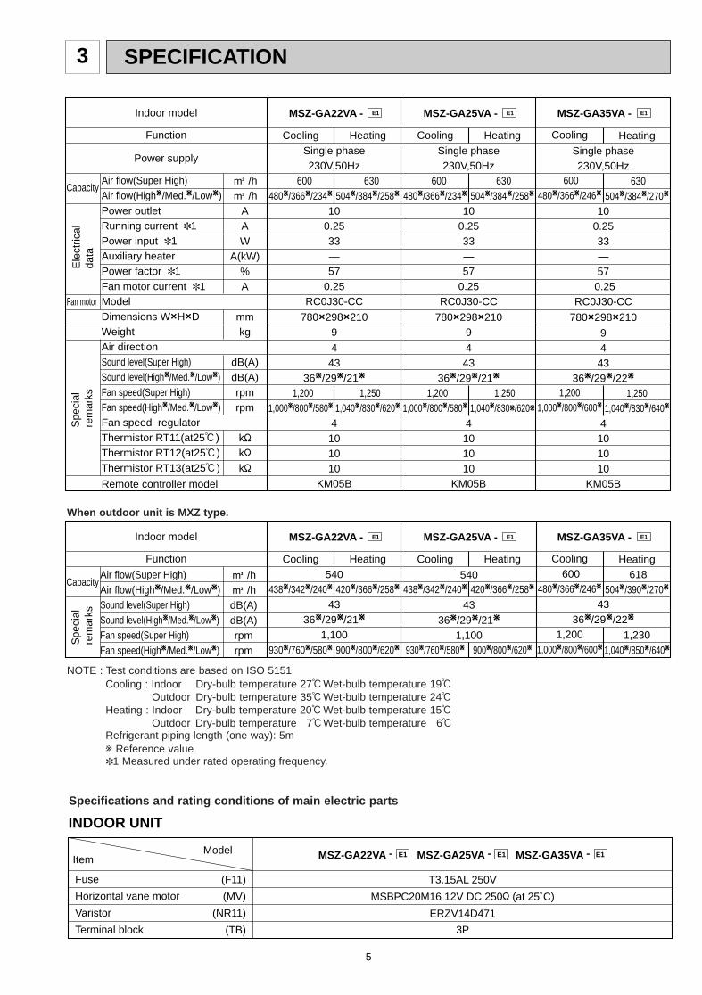
SPECIFICATION3
T3.15AL 250V
MSBPC20M16 12V DC 250" (at 25˚C)
ERZV14D471
3P
INDOOR UNIT
ItemModel
Fuse
Horizontal vane motor
Varistor
Terminal block
MSZ-GA22VA - E1 MSZ-GA25VA - E1 MSZ-GA35VA - E1
(F11)
(MV)
(NR11)
(TB)
Specifications and rating conditions of main electric parts
MSZ-GA25VA - E1 MSZ-GA22VA - E1 MSZ-GA35VA - E1 Indoor model
Function
Power supplySingle phase230V,50Hz
100.2533—57
0.25RC0J30-CC
780O298O2109
4 43
36W/29W/21W
4101010
KM05B
Single phase230V,50Hz
100.2533—57
0.25RC0J30-CC
780O298O2109
4 43
36W/29W/21W
4101010
KM05B
540
4336W/29W/21W
1,100
4336W/29W/22W
Cooling
600480W/366W/234W
1,2001,000W/800W/580W
Heating
630504W/384W/258W
1,2501,040W/830W/620W
Cooling
600480W/366W/234W
1,2001,000W/800W/580W
Heating
630504W/384W/258W
1,2501,040W/830W/620W
Single phase230V,50Hz
10 0.2533—57
0.25 RC0J30-CC
780O298O210
94
4336W/29W/22W
4101010
KM05B
Cooling
600480W/366W/246W
1,200
1,000W/800W/600W
Heating
630504W/384W/270W
1,250
1,040W/830W/640W
Air flow(Super High)Air flow(HighW/Med.W/LowW)Power outletRunning current ✽1Power input ✽1Auxiliary heaterPower factor ✽1Fan motor current ✽1ModelDimensions WOHODWeightAir directionSound level(Super High)Sound level(HighW/Med.W/LowW)Fan speed(Super High)Fan speed(HighW/Med.W/LowW)Fan speed regulatorThermistor RT11(at25:)Thermistor RT12(at25:)Thermistor RT13(at25:)
Remote controller model
K /hK /h
AAW
A(kW)%A
mmkg
dB(A)dB(A)rpmrpm
k"k"k"
Ele
ctric
alda
ta
Fan motor
Spe
cial
rem
arks
Capacity
MSZ-GA25VA - E1 MSZ-GA22VA - E1 MSZ-GA35VA - E1 Indoor model
Function Cooling
438W/342W/240W
930W/760W/580W
Heating
420W/366W/258W
900W/800W/620W
Cooling
438W/342W/240W
930W/760W/580W
Heating
420W/366W/258W
900W/800W/620W
Cooling 600
480W/366W/246W
1,2001,000W/800W/600W
Heating 618
504W/390W/270W
1,2301,040W/850W/640W
Air flow(Super High)Air flow(HighW/Med.W/LowW)Sound level(Super High)Sound level(HighW/Med.W/LowW)Fan speed(Super High)Fan speed(HighW/Med.W/LowW)
K /hK /hdB(A)dB(A)rpmrpm
Spe
cial
rem
arks
Capacity540
4336W/29W/21W
1,100
NOTE : Test conditions are based on ISO 5151Cooling : Indoor Dry-bulb temperature 27:Wet-bulb temperature 19:
Outdoor Dry-bulb temperature 35:Wet-bulb temperature 24:Heating : Indoor Dry-bulb temperature 20:Wet-bulb temperature 15:
Outdoor Dry-bulb temperature 7:Wet-bulb temperature 6:Refrigerant piping length (one way): 5mw Reference value✽1 Measured under rated operating frequency.
When outdoor unit is MXZ type.
OB378_--1qxp 05.1.17 12:55 Page 5
6
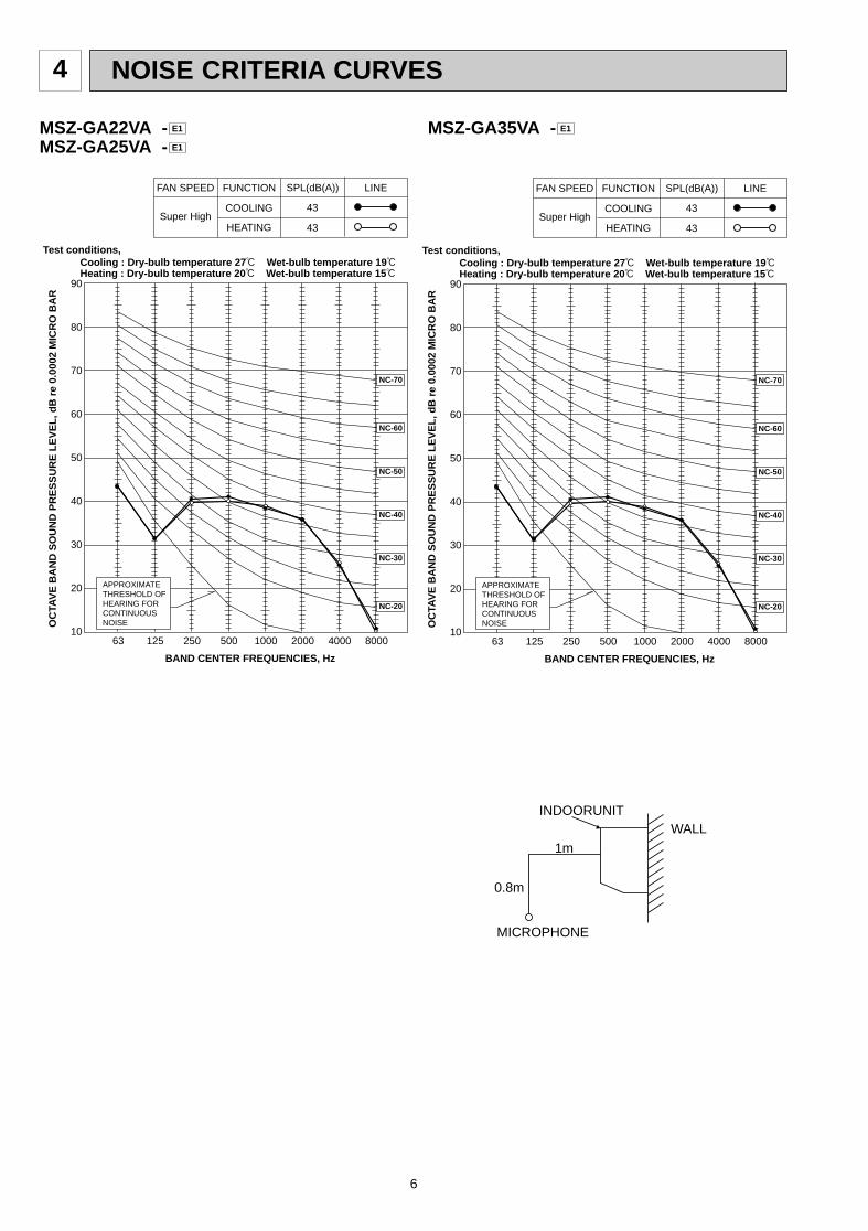
4 NOISE CRITERIA CURVES
90
80
70
60
50
40
30
20
1063 125 250 500 1000 2000 4000 8000
NC-60
NC-50
NC-40
NC-30
NC-20
NC-70
OC
TAV
E B
AN
D S
OU
ND
PR
ES
SU
RE
LE
VE
L, d
B r
e 0.
0002
MIC
RO
BA
R
BAND CENTER FREQUENCIES, Hz
Test conditions, Cooling : Dry-bulb temperature 27: Wet-bulb temperature 19:
APPROXIMATETHRESHOLD OF HEARING FORCONTINUOUSNOISE
COOLING
FUNCTION
43
43
SPL(dB(A)) LINE
Super High
FAN SPEED
HEATING
Heating : Dry-bulb temperature 20: Wet-bulb temperature 15:
MSZ-GA22VA -MSZ-GA25VA - E1
E1
INDOORUNITWALL
MICROPHONE
0.8m
1m
90
80
70
60
50
40
30
20
1063 125 250 500 1000 2000 4000 8000
NC-60
NC-50
NC-40
NC-30
NC-20
NC-70
OC
TAV
E B
AN
D S
OU
ND
PR
ES
SU
RE
LE
VE
L, d
B r
e 0.
0002
MIC
RO
BA
R
BAND CENTER FREQUENCIES, Hz
Test conditions, Cooling : Dry-bulb temperature 27: Wet-bulb temperature 19:
APPROXIMATETHRESHOLD OF HEARING FORCONTINUOUSNOISE
COOLING
FUNCTION
43
43
SPL(dB(A)) LINE
Super High
FAN SPEED
HEATING
Heating : Dry-bulb temperature 20: Wet-bulb temperature 15:
MSZ-GA35VA - E1
OB378_--1qxp 05.1.17 12:55 Page 6
7
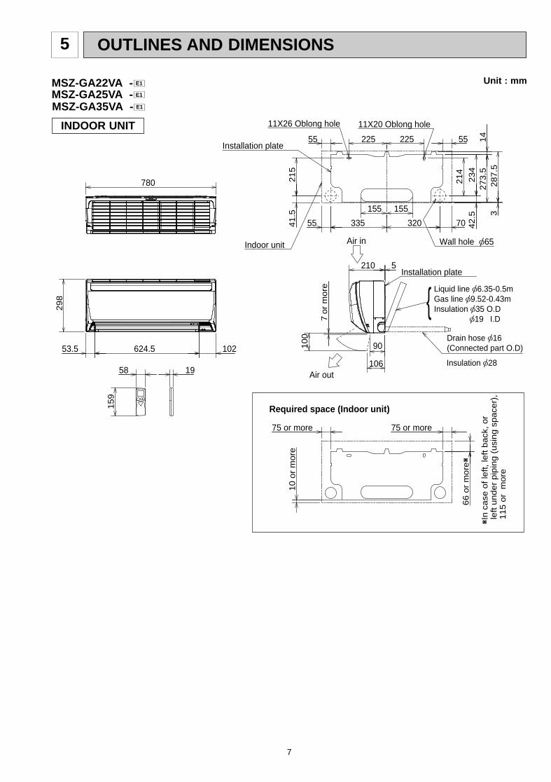
OUTLINES AND DIMENSIONS5
MSZ-GA25VA - E1
Unit : mm
INDOOR UNIT
155 155
335 32041
.52
15
42
.5
21
4
32
87
.5
7055
5555 225 225
or
mo
re7
10
0
90
106
29
8
102624.5
780
210 5
53.5
19
15
9
58
14
27
3.5
23
4
Air in
Air out
Wall hole [65Indoor unit
Installation plate
Installation plate
11X20 Oblong hole11X26 Oblong hole
10
or
mo
re
75 or more
66
or
mo
reW
75 or more
WIn
ca
se o
f le
ft,
left
ba
ck,
or
le
ft u
nd
er
pip
ing
(u
sin
g s
pa
cer)
,
11
5 o
r m
ore
Insulation [28
Drain hose [16(Connected part O.D)
Liquid line [6.35-0.5mGas line [9.52-0.43mInsulation [35 O.D [19 I.D
{
Required space (Indoor unit)
MSZ-GA35VA - E1
MSZ-GA22VA - E1
OB378_--1qxp 05.1.17 12:55 Page 7
8
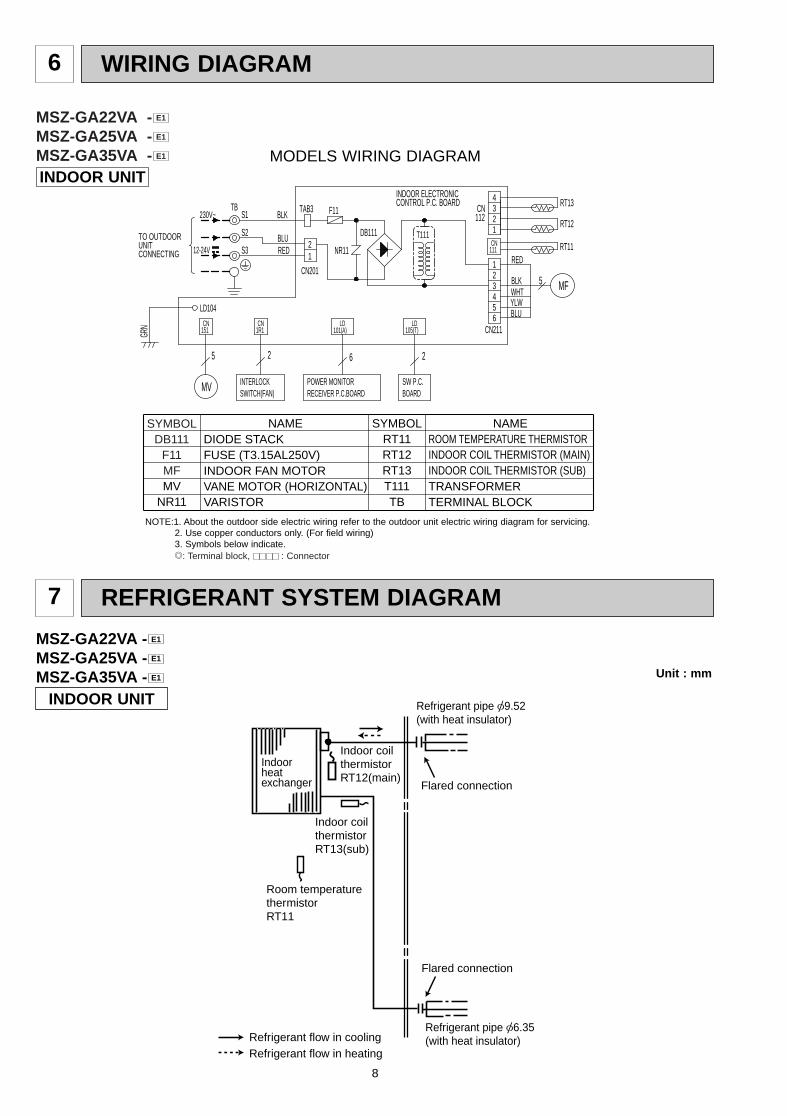
6 WIRING DIAGRAM
REFRIGERANT SYSTEM DIAGRAM7
MSZ-GA22VA -MSZ-GA25VA -MSZ-GA35VA - E1
E1
E1
Indoorheatexchanger Flared connection
Room temperaturethermistorRT11
Indoor coil thermistorRT13(sub)
Flared connection
Refrigerant flow in coolingRefrigerant flow in heating
Refrigerant pipe [9.52(with heat insulator)
Refrigerant pipe [6.35(with heat insulator)
Indoor coil thermistorRT12(main)
INDOOR UNIT
Unit : mm
INDOOR UNITMODELS WIRING DIAGRAM
SYMBOLDB111
F11MFMV
NR11
SYMBOLRT11RT12RT13T111TB
NAMEDIODE STACKFUSE (T3.15AL250V)INDOOR FAN MOTORVANE MOTOR (HORIZONTAL)VARISTOR
NAMEROOM TEMPERATURE THERMISTORINDOOR COIL THERMISTOR (MAIN)INDOOR COIL THERMISTOR (SUB)TRANSFORMERTERMINAL BLOCK
NOTE:1. About the outdoor side electric wiring refer to the outdoor unit electric wiring diagram for servicing.2. Use copper conductors only. (For field wiring)3. Symbols below indicate./: Terminal block, : Connector
MSZ-GA22VA -MSZ-GA25VA -MSZ-GA35VA - E1
E1
E1
4321S2
POWER MONITORRECEIVER P.C.BOARD
2 6
230V~
BLU
INDOOR ELECTRONIC CONTROL P.C. BOARD
SW P.C.BOARD
INTERLOCKSWITCH(FAN)
5
MV
TO OUTDOORUNITCONNECTING
BLK
REDS3
TB TAB3
DB111
NR11
F11
5
6
4
2
2
LD105(T)
LD101(A)
12-24V
RT13
1R1CN
GRN
LD104
CN201
21
151CN
T111
RED
WHT
111CN
CN112
CN211
BLUYLW
BLK MF
RT11
RT12
1
3
5
S1
OB378_--1qxp 05.1.17 12:55 Page 8
9
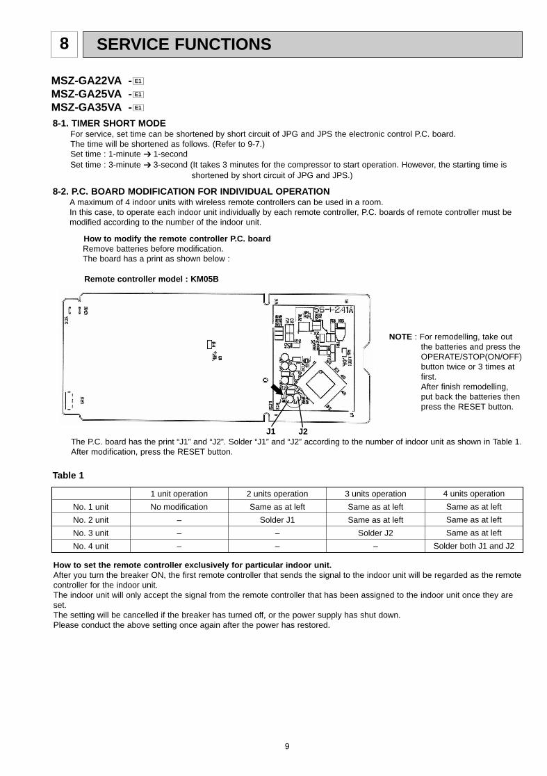
SERVICE FUNCTIONS8
8-2. P.C. BOARD MODIFICATION FOR INDIVIDUAL OPERATIONA maximum of 4 indoor units with wireless remote controllers can be used in a room.In this case, to operate each indoor unit individually by each remote controller, P.C. boards of remote controller must bemodified according to the number of the indoor unit.
8-1. TIMER SHORT MODEFor service, set time can be shortened by short circuit of JPG and JPS the electronic control P.C. board.The time will be shortened as follows. (Refer to 9-7.)Set time : 1-minute ➔ 1-secondSet time : 3-minute ➔ 3-second (It takes 3 minutes for the compressor to start operation. However, the starting time is
shortened by short circuit of JPG and JPS.)
No. 1 unit
No. 2 unit
No. 3 unit
No. 4 unit
1 unit operation
No modification
–
–
–
2 units operation
Same as at left
Solder J1
–
–
3 units operation
Same as at left
Same as at left
Solder J2
–
4 units operation
Same as at left
Same as at left
Same as at left
Solder both J1 and J2
Table 1
How to set the remote controller exclusively for particular indoor unit.After you turn the breaker ON, the first remote controller that sends the signal to the indoor unit will be regarded as the remotecontroller for the indoor unit.The indoor unit will only accept the signal from the remote controller that has been assigned to the indoor unit once they areset.The setting will be cancelled if the breaker has turned off, or the power supply has shut down.Please conduct the above setting once again after the power has restored.
How to modify the remote controller P .C. boardRemove batteries before modification.The board has a print as shown below :
The P.C. board has the print “J1” and “J2”. Solder “J1” and “J2” according to the number of indoor unit as shown in Table 1.After modification, press the RESET button.
NOTE : For remodelling, take outthe batteries and press theOPERATE/STOP(ON/OFF)button twice or 3 times atfirst.After finish remodelling,put back the batteries thenpress the RESET button.
Remote controller model : KM05B
J2J1
MSZ-GA22VA -MSZ-GA25VA -MSZ-GA35VA - E1
E1
E1
OB378_--1qxp 05.1.17 12:55 Page 9
TROUBLESHOOTING9
10
9-1. Cautions on troubleshooting1. Before troubleshooting, check the following:
1) Check the power supply voltage.2) Check the indoor/outdoor connecting wire for mis-wiring.
2. Take care the following during servicing.1) Before servicing the air conditioner, be sure to turn off the unit first with the remote controller, and then after
confirming the horizontal vane is closed, turn off the breaker and / or disconnect the power plug.2) Be sure to turn OFF the power supply before removing the front panel, the cabinet, the top panel, and the
electronic control P.C. board.3) When removing the electronic control P.C. board, hold the edge of the board with care NOT to apply stress on the
components.4) When connecting or disconnecting the connectors, hold the housing of the connector. DO NOT pull the lead wires.
Housing pointLead wiring
MSZ-GA22VA - MSZ-GA25VA - MSZ-GA35VA - E1E1E1
NOTE:• The operation settings are memorized when 10 seconds have passed after the indoor unit was operated with the
remote controller.• If main power is turned OFF or a power failure occurs while AUTO START/STOP timer is active, the timer setting is
cancelled.• If the unit has been off with the remote controller before power failure, the auto restart function does not work as the
power button of the remote controller is off.• To prevent breaker off due to the rush of starting current, systematize other home appliance not to turn on at the
same time.• When some air conditioners are connected to the same supply system, if they are operated before power failure,
the starting current of all the compressors may flow simultaneously at restart.Therefore, the special counter-measures are required to prevent the main voltage-drop or the rush of the startingcurrent by adding to the system that allows the units to start one by one.
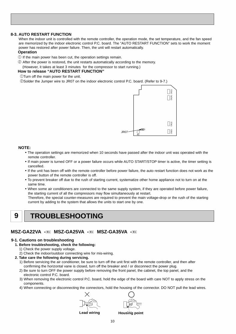
JR07 CN15
1CN
211
CN11
2CN
1R1
BZ
8-3. AUTO RESTART FUNCTIONWhen the indoor unit is controlled with the remote controller, the operation mode, the set temperature, and the fan speedare memorized by the indoor electronic control P.C. board. The “AUTO RESTART FUNCTION” sets to work the momentpower has restored after power failure. Then, the unit will restart automatically. Operation1 If the main power has been cut, the operation settings remain.2 After the power is restored, the unit restarts automatically according to the memory.
(However, it takes at least 3 minutes for the compressor to start running.)How to release “AUT O RESTART FUNCTION”1Turn off the main power for the unit.2Solder the Jumper wire to JR07 on the indoor electronic control P.C. board. (Refer to 9-7.)
OB378_--1qxp 05.1.17 12:55 Page 10
11
21 Stopper
Lock.
Left
Insert this end first.
3. Troubleshooting procedure1) First, check if the OPERATION INDICATOR lamp on the indoor unit is flashing on and off to indicate an abnormality.
To make sure, check how many times the abnormality indication is flashing on and off before starting service work.2) Before servicing check that the connector and terminal are connected properly.3) If the electronic control P.C. board is supposed to be defective, check the copper foil pattern for disconnection and the
components for bursting and discoloration.4) When troubleshooting, refer to 9-2., 9-3. and 9-4.
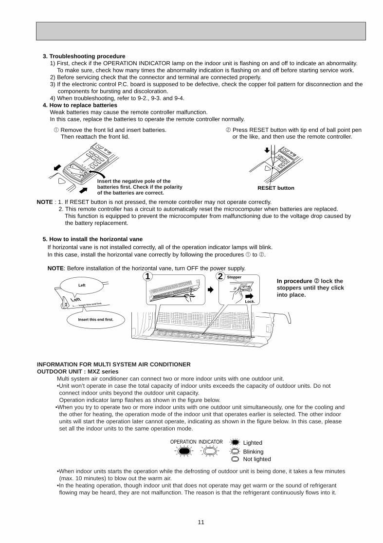
4. How to replace batteriesWeak batteries may cause the remote controller malfunction.In this case, replace the batteries to operate the remote controller normally.
RESET buttonInsert the negative pole of the batteries first. Check if the polarity of the batteries are correct.
NOTE : 1. If RESET button is not pressed, the remote controller may not operate correctly.2. This remote controller has a circuit to automatically reset the microcomputer when batteries are replaced.
This function is equipped to prevent the microcomputer from malfunctioning due to the voltage drop caused by the battery replacement.
2 Press RESET button with tip end of ball point penor the like, and then use the remote controller.
1 Remove the front lid and insert batteries.Then reattach the front lid.
If horizontal vane is not installed correctly, all of the operation indicator lamps will blink.In this case, install the horizontal vane correctly by following the procedures 1 to 2.
NOTE: Before installation of the horizontal vane, turn OFF the power supply.
5. How to install the horizontal vane
In procedure 22 lock thestoppers until they clickinto place.
INFORMATION FOR MULTI SYSTEM AIR CONDITIONER OUTDOOR UNIT : MXZ series
Multi system air conditioner can connect two or more indoor units with one outdoor unit. •Unit won’t operate in case the total capacity of indoor units exceeds the capacity of outdoor units. Do not connect indoor units beyond the outdoor unit capacity.Operation indicator lamp flashes as shown in the figure below.
•When you try to operate two or more indoor units with one outdoor unit simultaneously, one for the cooling andthe other for heating, the operation mode of the indoor unit that operates earlier is selected. The other indoor units will start the operation later cannot operate, indicating as shown in the figure below. In this case, please set all the indoor units to the same operation mode.
•When indoor units starts the operation while the defrosting of outdoor unit is being done, it takes a few minutes(max. 10 minutes) to blow out the warm air.
•In the heating operation, though indoor unit that does not operate may get warm or the sound of refrigerantflowing may be heard, they are not malfunction. The reason is that the refrigerant continuously flows into it.
OPERATION INDICATOR
Not lightedBlinking
Lighted
OB378_--1qxp 05.1.17 12:55 Page 11
12
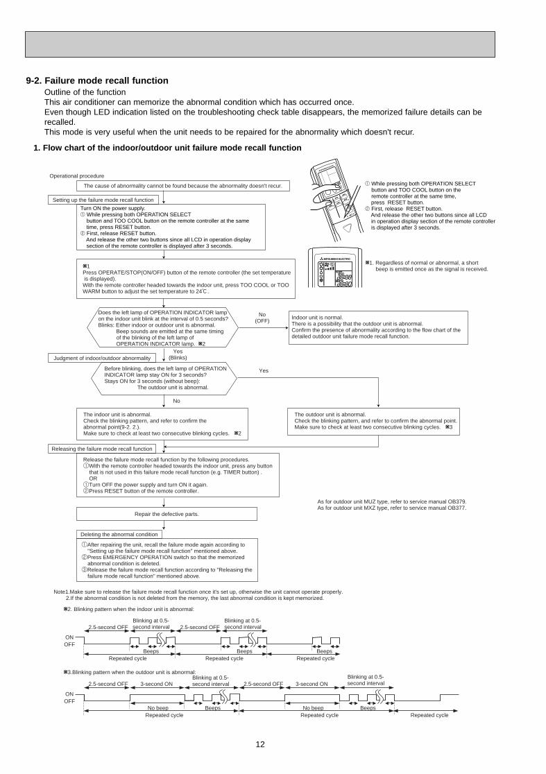
Outline of the functionThis air conditioner can memorize the abnormal condition which has occurred once.Even though LED indication listed on the troubleshooting check table disappears, the memorized failure details can berecalled.This mode is very useful when the unit needs to be repaired for the abnormality which doesn't recur.
9-2. Failure mode recall function
1. Flow chart of the indoor/outdoor unit failure mode recall function
Operational procedure
Yes(Blinks)
No(OFF)
Yes
No
Releasing the failure mode recall function
W1. Regardless of normal or abnormal, a short beep is emitted once as the signal is received.
Note1.Make sure to release the failure mode recall function once it's set up, otherwise the unit cannot operate properly. 2.If the abnormal condition is not deleted from the memory, the last abnormal condition is kept memorized.
W2. Blinking pattern when the indoor unit is abnormal:
W3.Blinking pattern when the outdoor unit is abnormal:
ONOFF
BeepsRepeated cycle Repeated cycle
ONOFF
No beep BeepsRepeated cycle
2.5-second OFFBlinking at 0.5-second interval
2.5-second OFF 3-second ONBlinking at 0.5-second interval
BeepsRepeated cycle
2.5-second OFFBlinking at 0.5-second interval
No beep BeepsRepeated cycle
2.5-second OFF 3-second ONBlinking at 0.5-second interval
Repeated cycle
Beeps
Does the left lamp of OPERATION INDICATOR lamp on the indoor unit blink at the interval of 0.5 seconds?Blinks: Either indoor or outdoor unit is abnormal. Beep sounds are emitted at the same timing of the blinking of the left lamp of OPERATION INDICATOR lamp. W2
The cause of abnormality cannot be found because the abnormality doesn't recur.
Setting up the failure mode recall function
Before blinking, does the left lamp of OPERATION INDICATOR lamp stay ON for 3 seconds?Stays ON for 3 seconds (without beep): The outdoor unit is abnormal.
The indoor unit is abnormal.Check the blinking pattern, and refer to confirm theabnormal point(9-2. 2.).Make sure to check at least two consecutive blinking cycles. W2
Turn ON the power supply.1 While pressing both OPERATION SELECT button and TOO COOL button on the remote controller at the same time, press RESET button.2 First, release RESET button. And release the other two buttons since all LCD in operation display section of the remote controller is displayed after 3 seconds.
Deleting the abnormal condition
1After repairing the unit, recall the failure mode again according to "Setting up the failure mode recall function" mentioned above.2Press EMERGENCY OPERATION switch so that the memorized abnormal condition is deleted.3Release the failure mode recall function according to "Releasing the failure mode recall function" mentioned above.
Repair the defective parts.
Release the failure mode recall function by the following procedures.1With the remote controller headed towards the indoor unit, press any button that is not used in this failure mode recall function (e.g. TIMER button) . OR1Turn OFF the power supply and turn ON it again.2Press RESET button of the remote controller.
Judgment of indoor/outdoor abnormality
W1Press OPERATE/STOP(ON/OFF) button of the remote controller (the set temperature is displayed).With the remote controller headed towards the indoor unit, press TOO COOL or TOOWARM button to adjust the set temperature to 24:.
Indoor unit is normal. There is a possibility that the outdoor unit is abnormal.Confirm the presence of abnormality according to the flow chart of the detailed outdoor unit failure mode recall function.
The outdoor unit is abnormal.Check the blinking pattern, and refer to confirm the abnormal point.Make sure to check at least two consecutive blinking cycles. W3
1 While pressing both OPERATION SELECT button and TOO COOL button on the
remote controller at the same time, press RESET button.2 First, release RESET button. And release the other two buttons since all LCD in operation display section of the remote controller is displayed after 3 seconds.
As for outdoor unit MUZ type, refer to service manual OB379.As for outdoor unit MXZ type, refer to service manual OB377.
OB378_--1qxp 05.1.17 12:55 Page 12
13
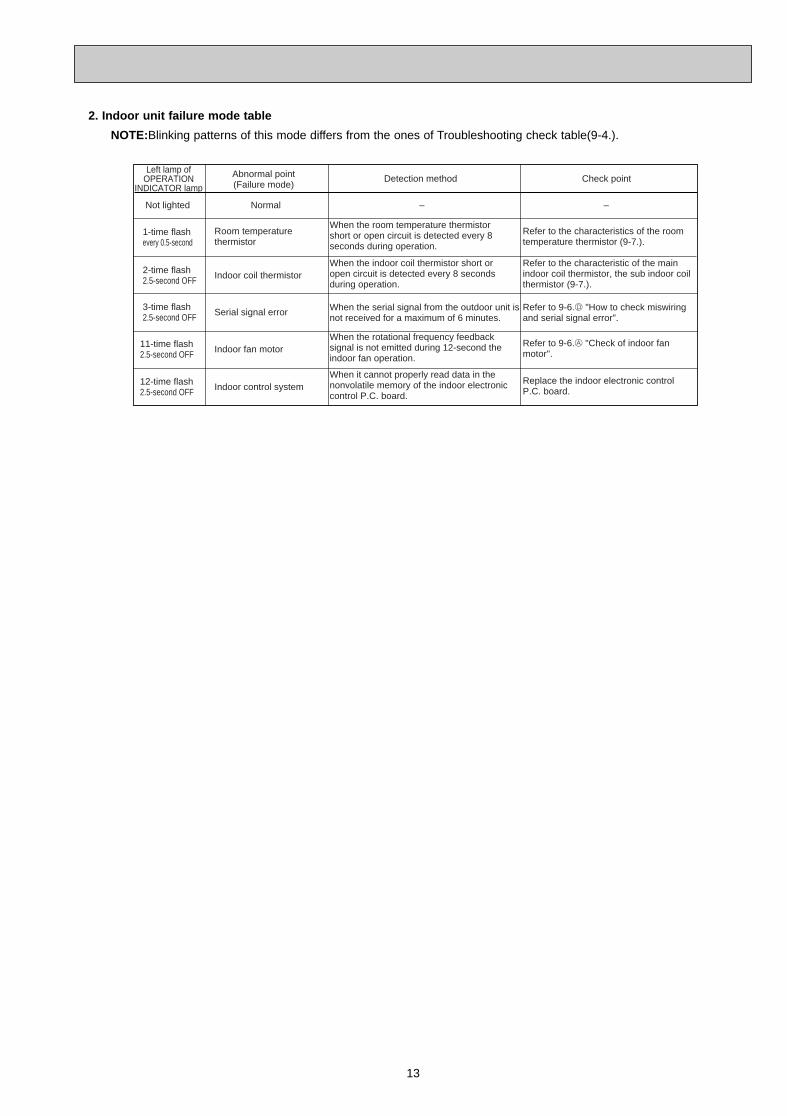
2. Indoor unit failure mode table
NOTE:Blinking patterns of this mode differs from the ones of Troubleshooting check table(9-4.).
12-time flash2.5-second OFF
Replace the indoor electronic controlP.C. board.Indoor control system
When it cannot properly read data in thenonvolatile memory of the indoor electroniccontrol P.C. board.
11-time flash2.5-second OFF
Refer to 9-6.A "Check of indoor fanmotor".Indoor fan motor
When the rotational frequency feedbacksignal is not emitted during 12-second the indoor fan operation.
2-time flash2.5-second OFF
Refer to the characteristic of the mainindoor coil thermistor, the sub indoor coilthermistor (9-7.).
Indoor coil thermistorWhen the indoor coil thermistor short or open circuit is detected every 8 secondsduring operation.
3-time flash2.5-second OFF
Refer to 9-6.D "How to check miswiringand serial signal error".
Serial signal error When the serial signal from the outdoor unit is not received for a maximum of 6 minutes.
1-time flashevery 0.5-second
Refer to the characteristics of the roomtemperature thermistor (9-7.).
Room temperaturethermistor
When the room temperature thermistor short or open circuit is detected every 8seconds during operation.
Not lighted –Normal –
Left lamp of OPERATION
INDICATOR lampCheck pointAbnormal point
(Failure mode)Detection method
OB378_--1qxp 05.1.17 12:55 Page 13
14
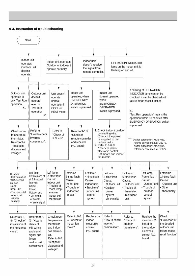
Start
Indoor unit operates.Outdoor unit doesn't operate.
Indoor unit doesn't receive the signal from remote controller.
OPERATION INDICATORlamp on the indoor unit is flashing on and off.
Outdoor unit operates in only Test Run operation. w1
Outdoor unit doesn't operate even in Test Run operation. w1
Indoor unit operates, when EMERGENCY OPERATION switch is pressed.
Indoor unit doesn't operate, when EMERGENCY OPERATION switch is pressed.
Check room temperature thermistor.Refer to 9-7. "Test point diagram and voltage".
Refer to"How to check inverter/compressor".
Refer to 9-6.B "Check of remote controller and receiver P.C. board".
1. Check indoor / outdoor connecting wire. (Check if the power is supplied to the indoor unit.)2. Refer to 9-6.C "Check of indoor electronic control P.C. board and indoor fan motor".
Unit doesn't operate normaloperation in COOL or HEAT mode.
Refer to "Check of R.V. coil".
Left lamp Flash on and offat 0.5-secondintervalsCause: Indoor/Outdoor unit• Mis-wiring or trouble of serial signal
Left lamp2-time flash Cause:Indoor unit• Trouble of room temp- erature/ indoor coil thermistor
Left lamp3-time flash Cause:Indoor unit• Trouble of indoor fan motor
Left lamp5-time flash Cause: Outdoor unit• Outdoor power system abnormality
Left lamp6-time flash Cause: Outdoor unit• Trouble of thermistor in outdoor unit
Left lamp7-time flash Cause: Outdoor unit• Trouble of outdoor control system
Refer to 9-6.D "How to check ofmis-wiringand serialsignal error (when outdoor unit doesn't work)".
All lamps Flash on and off at 0.5-second intervals Cause:Indoor unit• The horizontal vane is not installed correctly.
Refer to 9-6.E "Check of installation of the horizontalvane".
Check room temperature thermistor and indoor coil thermis-tor.Refer to 9-7."Test point diagram and voltage".
Refer to 9-6.A "Check of indoor fan motor".
Refer to "How to checkinverter/ compressor".
Refer to "Check of outdoor thermistors".
Replace the inverter P.C. board or the outdoor electronic control P.C. board.
Left lamp14-time flash Cause: Outdoor unit• Other abnormality
Check "Flow chart of the detailed outdoor unit failure mode recall function."
Left lamp 4-time flash Cause:Indoor unit• Trouble of indoor unit control system
Replace the indoor electronic control P.C. board.
As for outdoor unit MUZ type, refer to service manual OB379.
As for outdoor unit MXZ type, refer to service manual OB377.
Indoor unit operates.Outdoor unit doesn'toperate normally.
If blinking of OPERATION INDICATOR lamp cannot bechecked, it can be checked with failure mode recall function.
w1"Test Run operation" means the operation within 30 minutes afterEMERGNCY OPERATION switch is pressed.
9-3. Instruction of troubleshooting
OB378_--1qxp 05.1.17 12:55 Page 14
15
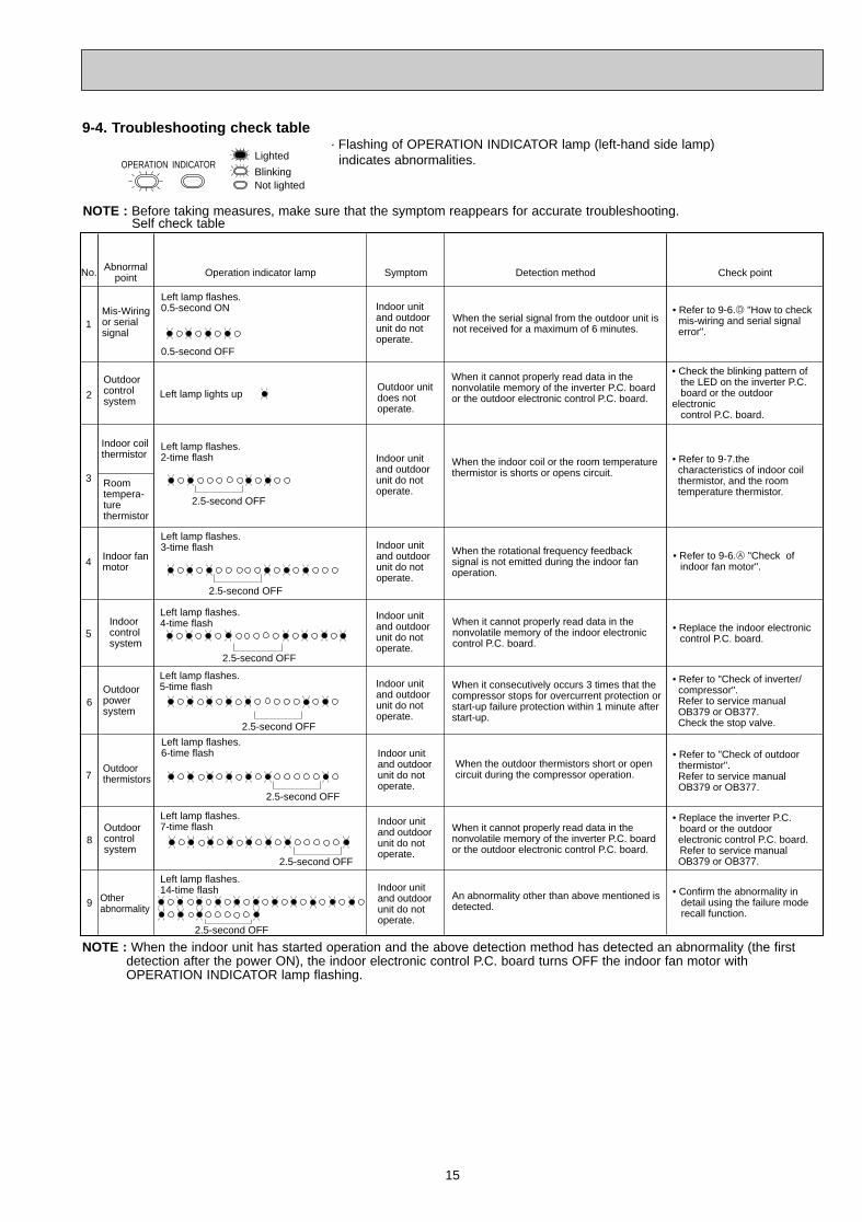
NOTE : When the indoor unit has started operation and the above detection method has detected an abnormality (the first detection after the power ON), the indoor electronic control P.C. board turns OFF the indoor fan motor with OPERATION INDICATOR lamp flashing.
No.
1
3
6
7
SymptomOperation indicator lamp Detection method Check point
Left lamp flashes.0.5-second ON
0.5-second OFF
Mis-Wiringor serial signal
Outdoor power system
Outdoor thermistors
Outdoor control system
Indoor coil thermistor
When the serial signal from the outdoor unit is not received for a maximum of 6 minutes.
When it consecutively occurs 3 times that the compressor stops for overcurrent protection or start-up failure protection within 1 minute after start-up.
When the outdoor thermistors short or open circuit during the compressor operation.
When it cannot properly read data in the nonvolatile memory of the inverter P.C. board or the outdoor electronic control P.C. board.
• Refer to "Check of outdoor thermistor".
Refer to service manual OB379 or OB377.
• Refer to "Check of inverter/compressor".
Refer to service manual OB379 or OB377. Check the stop valve.
• Replace the inverter P.C. board or the outdoor
electronic control P.C. board. Refer to service manual
OB379 or OB377.
• Refer to 9-6.D "How to check mis-wiring and serial signal
error".
4 Indoor fan motor
8
Abnormal point
Room tempera-ture thermistor
Left lamp flashes.2-time flash
2.5-second OFF
When the indoor coil or the room temperature thermistor is shorts or opens circuit.
• Refer to 9-7.the characteristics of indoor coil thermistor, and the room temperature thermistor.
Left lamp flashes.3-time flash
2.5-second OFF
When the rotational frequency feedback signal is not emitted during the indoor fan operation.
• Refer to 9-6.A "Check of indoor fan motor".
Indoor unit and outdoor unit do not operate.
Indoor unit and outdoor unit do not operate.
Left lamp flashes.5-time flash
2.5-second OFF
Left lamp flashes.6-time flash
2.5-second OFF
Indoor unit and outdoor unit do not operate.
Indoor unit and outdoor unit do not operate.
Indoor unit and outdoor unit do not operate.
Other abnormality
An abnormality other than above mentioned is detected.
• Confirm the abnormality in detail using the failure mode recall function.
Indoor unit and outdoor unit do not operate.
Indoor unit and outdoor unit do not operate.
9
5
Left lamp flashes.4-time flash
2.5-second OFF
Indoor control system
When it cannot properly read data in the nonvolatile memory of the indoor electronic control P.C. board.
Indoor unit and outdoor unit do not operate.
• Replace the indoor electronic control P.C. board.
Outdoor control system
When it cannot properly read data in the nonvolatile memory of the inverter P.C. board or the outdoor electronic control P.C. board.
• Check the blinking pattern of the LED on the inverter P.C. board or the outdoor electronic control P.C. board.
2Outdoor unit does not operate.
Left lamp lights up
Left lamp flashes.7-time flash
2.5-second OFF
Left lamp flashes.14-time flash
2.5-second OFF
9-4. Troubleshooting check table
NOTE : Before taking measures, make sure that the symptom reappears for accurate troubleshooting.Self check table
Not lightedBlinking
OPERATION INDICATORLighted
· Flashing of OPERATION INDICATOR lamp (left-hand side lamp)indicates abnormalities.
OB378_--1qxp 05.1.17 12:55 Page 15
16
OPERATION INDICATOR
Not lightedBlinking
Lighted
OPERATION INDICATOR
Not lightedBlinking
Lighted
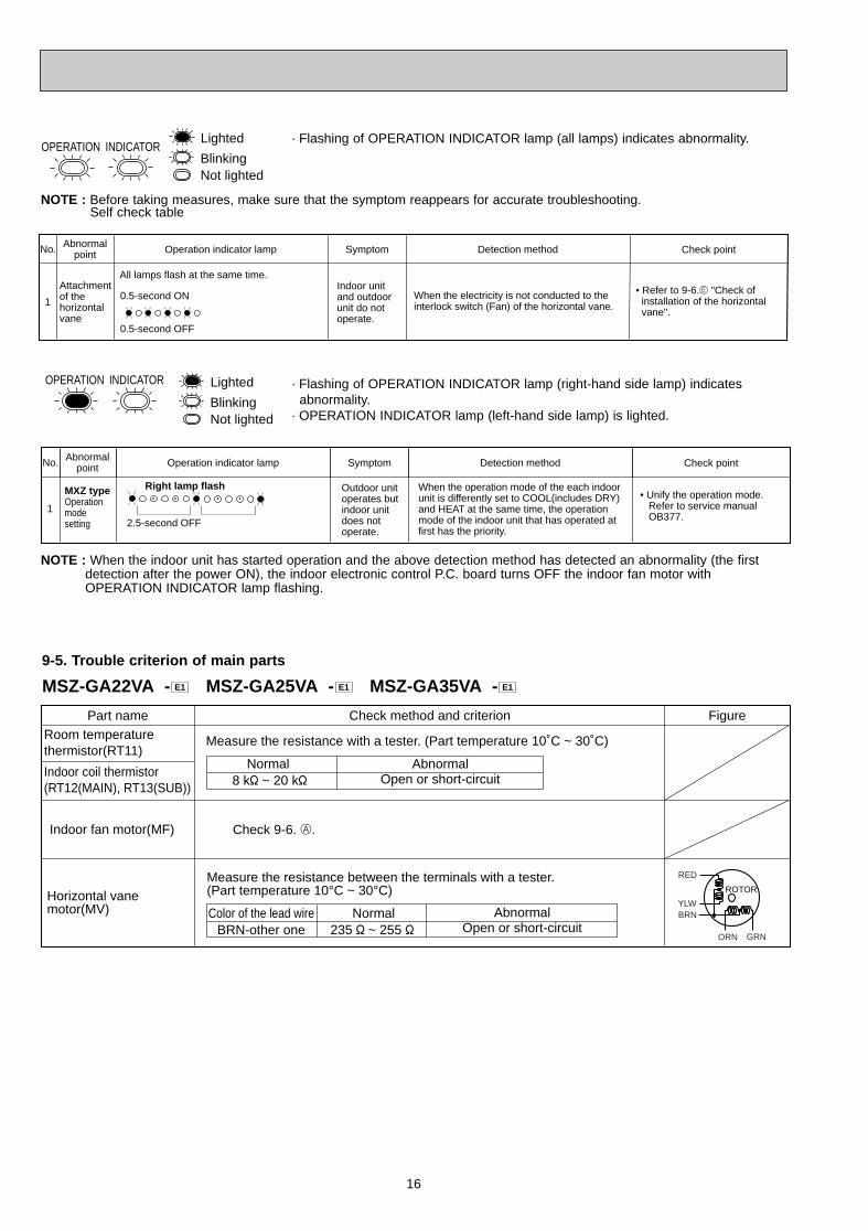
NOTE : When the indoor unit has started operation and the above detection method has detected an abnormality (the first detection after the power ON), the indoor electronic control P.C. board turns OFF the indoor fan motor with OPERATION INDICATOR lamp flashing.
No.
1
SymptomOperation indicator lamp Detection method Check pointAbnormal point
0.5-second ON
0.5-second OFF
When the electricity is not conducted to the interlock switch (Fan) of the horizontal vane.
• Refer to 9-6.E "Check of installation of the horizontal vane".
Indoor unit and outdoor unit do not operate.
Attachment of the horizontal vane
All lamps flash at the same time.
No. SymptomOperation indicator lamp Detection method Check pointAbnormal point
1
MXZ typeOperation mode setting
Outdoor unit operates but indoor unit does not operate.
When the operation mode of the each indoor unit is differently set to COOL(includes DRY) and HEAT at the same time, the operation mode of the indoor unit that has operated at first has the priority.
• Unify the operation mode. Refer to service manual OB377.
2.5-second OFF
Right lamp flash
· Flashing of OPERATION INDICATOR lamp (all lamps) indicates abnormality.
· Flashing of OPERATION INDICATOR lamp (right-hand side lamp) indicates abnormality.
· OPERATION INDICATOR lamp (left-hand side lamp) is lighted.
NOTE : Before taking measures, make sure that the symptom reappears for accurate troubleshooting.Self check table
9-5. Trouble criterion of main parts
MSZ-GA22VA - MSZ-GA25VA - MSZ-GA35VA - E1E1E1
Part name FigureCheck method and criterion
Indoor fan motor(MF)
Measure the resistance with a tester. (Part temperature 10˚C ~ 30˚C)
Normal8 k" ~ 20 k"
AbnormalOpen or short-circuit
Room temperaturethermistor(RT11)
Indoor coil thermistor(RT12(MAIN), RT13(SUB))
Horizontal vane motor(MV) Normal
BRN-other oneAbnormal
Open or short-circuit
Measure the resistance between the terminals with a tester.(Part temperature 10°C ~ 30°C)
235 " ~ 255 "Color of the lead wire
Check 9-6. A.
RED
YLWBRN
ORN GRN
ROTOR
OB378_--1qxp 05.1.17 12:55 Page 16
17
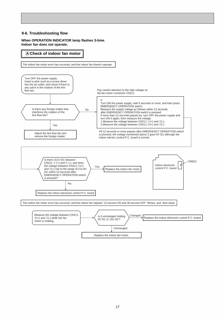
Check of indoor fan motorA
When OPERATION INDICATOR lamp flashes 3-time.Indoor fan does not operate.
wIf 12 seconds or more passes after EMERGENCY OPERATION switchis pressed, the voltage mentioned above 2 goes 0V DC although theindoor electric control P.C. board is normal.
Indoor electroniccontrol P.C. board
Pay careful attention to the high voltage onthe fan motor connector CN211.
Yes
No
No
Changed
Unchanged
Is there any foreign matter thatinterferes the rotation of theline flow fan?
Turn OFF the power supply.Insert a stick such as a screw driverinto the air outlet, and check if there isany catch in the rotation of the lineflow fan.
Adjust the line flow fan andremove the foreign matter.
wTurn ON the power supply, wait 5 seconds or more, and then pressEMERGENCY OPERATION switch.Measure the supply voltage as follows within 12 secondsafter EMERGENCY OPERATION switch is pressed.If more than 12 seconds passes by, turn OFF the power supply andturn ON it again, then measure the voltage.1.Measure the voltage between CN211 1(+) and 3(-).2.Measure the voltage between CN211 5(+) and 3(-).
Is there 311V DC betweenCN211 1 (+) and 3 (-), and does the voltage between CN211 5(+)and 3(-) rise to the range of 3 to 6VDC within 12 seconds after EMERGENCY OPERATION switch is pressed?
YesReplace the indoor fan motor.
CN211
Replace the indoor electronic control P.C. board.
The indoor fan motor error has occurred, and the indoor fan repeats "12-second ON and 30-second OFF" 3times, and then stops.
Measure the voltage between CN2116(+) and 3(-) while the fanmotor is rotating.
Is it unchanged holding0V DC or 15V DC?
Replace the indoor fan motor.
Replace the indoor electronic control P.C. board.
The indoor fan motor error has occurred, and the indoor fan doesn't operate.
9-6. Troubleshooting flow
OB378_--1qxp 05.1.17 12:55 Page 17
18
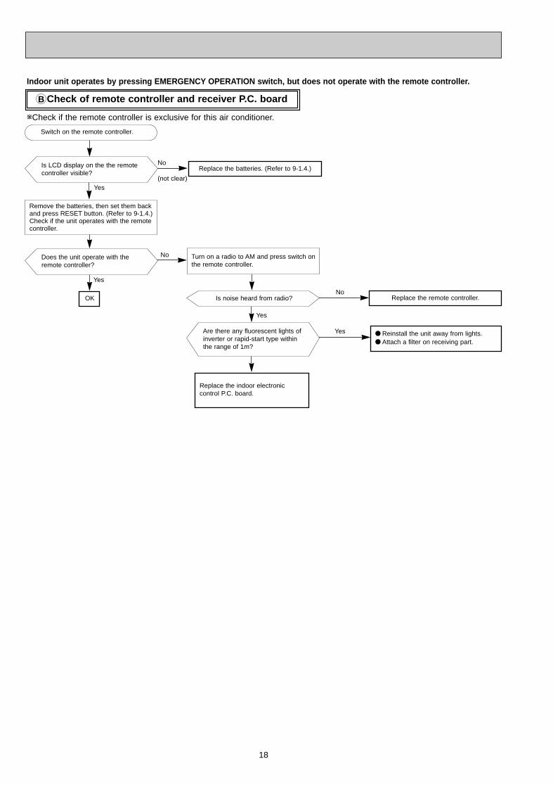
Check of remote controller and receiver P .C. board B
Indoor unit operates by pressing EMERGENCY OPERATION switch, but does not operate with the remote controller .
wCheck if the remote controller is exclusive for this air conditioner.
Yes
Replace the batteries. (Refer to 9-1.4.)
Turn on a radio to AM and press switch onthe remote controller.
Is noise heard from radio?
Are there any fluorescent lights ofinverter or rapid-start type withinthe range of 1m?
Replace the indoor electronic control P.C. board.
Replace the remote controller.
● Reinstall the unit away from lights.● Attach a filter on receiving part.
Switch on the remote controller.
Is LCD display on the the remotecontroller visible?
Remove the batteries, then set them backand press RESET button. (Refer to 9-1.4.)Check if the unit operates with the remotecontroller.
Yes
Does the unit operate with theremote controller?
Yes
OK
No
(not clear)
Yes
No
No
OB378_--1qxp 05.1.17 12:55 Page 18
19
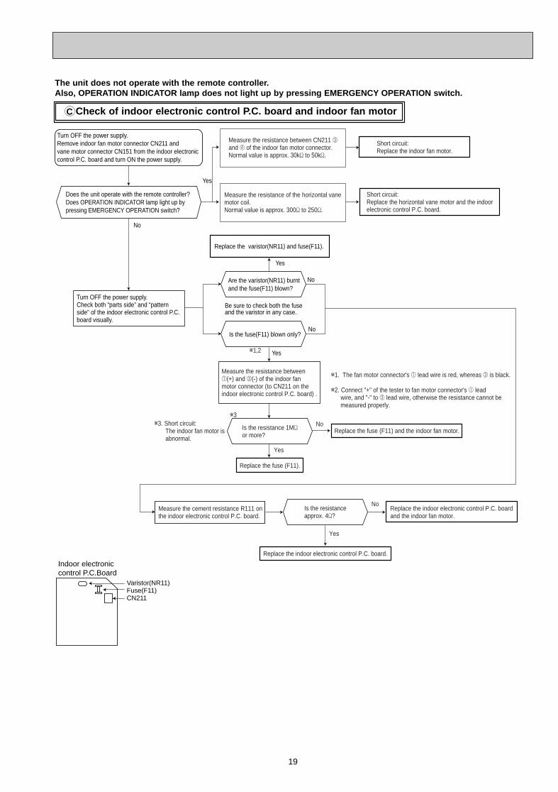
The unit does not operate with the remote controller .Also, OPERA TION INDICATOR lamp does not light up by pressing EMERGENCY OPERATION switch.
Check of indoor electronic control P .C. board and indoor fan motorC
Yes
No
w1. The fan motor connector's 1 lead wire is red, whereas 3 is black.
w2. Connect "+" of the tester to fan motor connector's 1 lead wire, and "-" to 3 lead wire, otherwise the resistance cannot be measured properly.
w3w3. Short circuit: The indoor fan motor is abnormal.
Yes
No
w1,2
Does the unit operate with the remote controller?Does OPERATION INDICATOR lamp light up by pressing EMERGENCY OPERATION switch?
Turn OFF the power supply.Remove indoor fan motor connector CN211 and vane motor connector CN151 from the indoor electronic control P.C. board and turn ON the power supply.
Measure the resistance of the horizontal vanemotor coil.Normal value is approx. 300' to 250'.
Measure the resistance between CN211 3and 4 of the indoor fan motor connector.Normal value is approx. 30k' to 50k'.
Short circuit:Replace the indoor fan motor.
Short circuit:Replace the horizontal vane motor and the indoorelectronic control P.C. board.
Turn OFF the power supply.Check both “parts side” and “pattern side” of the indoor electronic control P.C. board visually.
Replace the varistor(NR11) and fuse(F11).
Are the varistor(NR11) burntand the fuse(F11) blown?
Be sure to check both the fuse and the varistor in any case.
No
Yes
No
Is the fuse(F11) blown only?
Yes
No
Is the resistance 1M'or more?
Measure the resistance between1(+) and 3(-) of the indoor fanmotor connector (to CN211 on theindoor electronic control P.C. board) .
Replace the fuse (F11).
Replace the fuse (F11) and the indoor fan motor.
Is the resistanceapprox. 4'?
Measure the cement resistance R111 onthe indoor electronic control P.C. board.
Replace the indoor electronic control P.C. board.
Replace the indoor electronic control P.C. boardand the indoor fan motor.
Yes
CN211Fuse(F11)Varistor(NR11)
Indoor electroniccontrol P.C.Board
OB378_--1qxp 05.1.17 12:55 Page 19
20
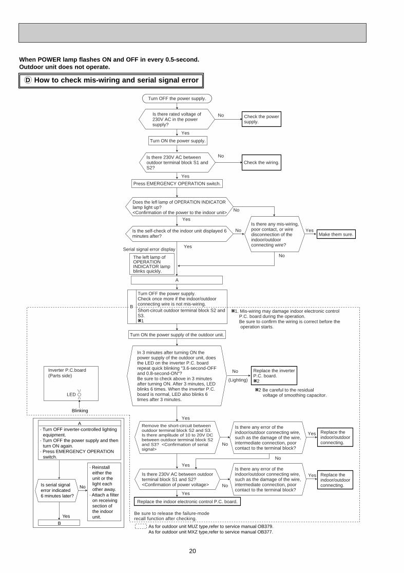
How to check mis-wiring and serial signal errorD
When POWER lamp flashes ON and OFF in every 0.5-second.Outdoor unit does not operate.
Is there rated voltage of230V AC in the powersupply?
In 3 minutes after turning ON thepower supply of the outdoor unit, doesthe LED on the inverter P.C. boardrepeat quick blinking "3.6-second-OFFand 0.8-second-ON"?Be sure to check above in 3 minutesafter turning ON. After 3 minutes, LEDblinks 6 times. When the inverter P.C.board is normal, LED also blinks 6times after 3 minutes.
Is there any mis-wiring, poor contact, or wire disconnection of the indoor/outdoor connecting wire?
W1. Mis-wiring may damage indoor electronic control P.C. board during the operation. Be sure to confirm the wiring is correct before the operation starts.
(Lighting)
No
Yes
No
Yes
Yes
No
Yes
No
Yes
No
W2 Be careful to the residual voltage of smoothing capacitor.
Be sure to release the failure-moderecall function after checking.
No
No
Yes
No
YesSerial signal error display
Yes
Yes
No
Yes
As for outdoor unit MUZ type,refer to service manual OB379.As for outdoor unit MXZ type,refer to service manual OB377.
Inverter P.C.board(Parts side)
LED
Blinking
Turn OFF the power supply.
Turn ON the power supply.
Is there 230V AC betweenoutdoor terminal block S1 andS2?
Does the lefl lamp of OPERATION INDICATOR lamp light up? <Confirmation of the power to the indoor unit>
Press EMERGENCY OPERATION switch.
Check the powersupply.
Is the self-check of the indoor unit displayed 6minutes after?
The left lamp of OPERATION INDICATOR lamp blinks quickly.
A
Turn OFF the power supply.Check once more if the indoor/outdoorconnecting wire is not mis-wiring.Short-circuit outdoor terminal block S2 andS3.W1
B
Turn ON the power supply of the outdoor unit.
Check the wiring.
Make them sure.
Remove the short-circuit betweenoutdoor terminal block S2 and S3.Is there amplitude of 10 to 20V DCbetween outdoor terminal block S2and S3? <Confirmation of serialsignal>
Is there 230V AC between outdoorterminal block S1 and S2?<Confirmation of power voltage>
Replace the indoor electronic control P.C. board.
Replace the inverterP.C. board.W2
Is there any error of theindoor/outdoor connecting wire,such as the damage of the wire,intermediate connection, poorcontact to the terminal block?
Is there any error of theindoor/outdoor connecting wire,such as the damage of the wire,intermediate connection, poorcontact to the terminal block?
Replace theindoor/outdoorconnecting.
Replace theindoor/outdoorconnecting.
Is serial signalerror indicated 6 minutes later?
Yes
No
· Turn OFF inverter-controlled lighting equipment.
· Turn OFF the power supply and then turn ON again.
· Press EMERGENCY OPERATION switch.
B
· Reinstall either the unit or the light each other away.
· Attach a filter on receiving section of the indoor unit.
A
OB378_--1qxp 05.1.17 12:55 Page 20
21
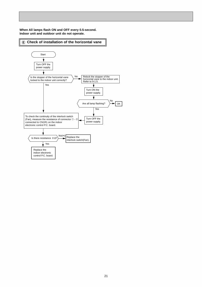
Check of installation of the horizontal vaneE
Start
Replace the indoor electronic control P.C. board.
Replace the interlock switch(Fan).
Is the stopper of the horizontal vane locked to the indoor unit correctly?
Yes
No
Is there resistance 0 "?
Relock the stopper of the horizontal vane to the indoor unit. Refer to 9-1.5.
Yes
Are all lamp flashing?
Yes
No(∞)
NoOK
Turn ON the power supply.
To check the continuity of the interlock switch(Fan), measure the resistance of connector 1 - 2 connected to CN1R1 on the indoor electronic control P.C. board.
Turn OFF the power supply.
Turn OFF the power supply.
When All lamps flash ON and OFF every 0.5-second. Indoor unit and outdoor unit do not operate.
OB378_--1qxp 05.1.17 12:55 Page 21
22
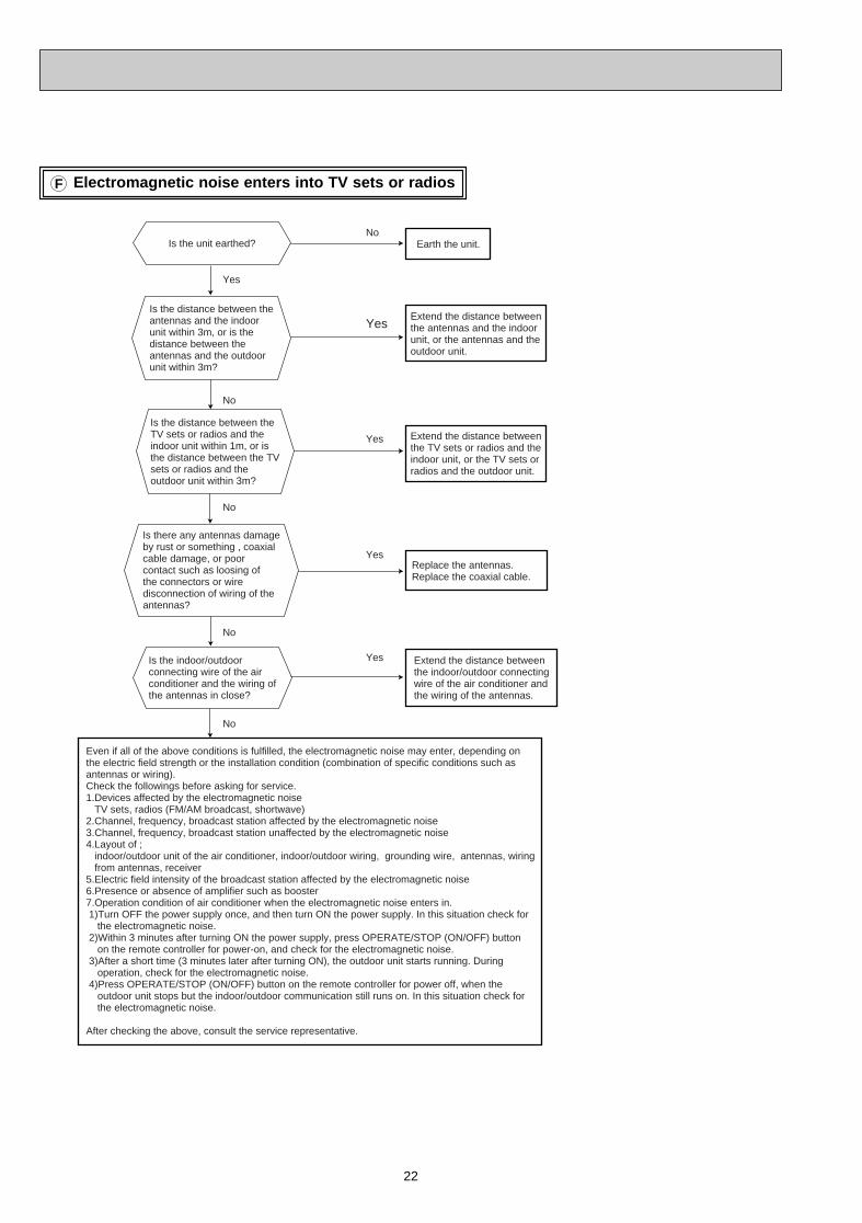
Electromagnetic noise enters into TV sets or radiosF
Replace the antennas.Replace the coaxial cable.
No
No
No
Yes
Yes
No
No
Yes
Yes
Yes
Is the distance between theantennas and the indoorunit within 3m, or is thedistance between theantennas and the outdoorunit within 3m?
Is the distance between theTV sets or radios and theindoor unit within 1m, or isthe distance between the TVsets or radios and theoutdoor unit within 3m?
Is there any antennas damageby rust or something , coaxialcable damage, or poorcontact such as loosing ofthe connectors or wiredisconnection of wiring of theantennas?
Is the indoor/outdoorconnecting wire of the airconditioner and the wiring ofthe antennas in close?
Even if all of the above conditions is fulfilled, the electromagnetic noise may enter, depending on the electric field strength or the installation condition (combination of specific conditions such as antennas or wiring).Check the followings before asking for service.1.Devices affected by the electromagnetic noise TV sets, radios (FM/AM broadcast, shortwave)2.Channel, frequency, broadcast station affected by the electromagnetic noise3.Channel, frequency, broadcast station unaffected by the electromagnetic noise4.Layout of ; indoor/outdoor unit of the air conditioner, indoor/outdoor wiring, grounding wire, antennas, wiring from antennas, receiver5.Electric field intensity of the broadcast station affected by the electromagnetic noise6.Presence or absence of amplifier such as booster7.Operation condition of air conditioner when the electromagnetic noise enters in. 1)Turn OFF the power supply once, and then turn ON the power supply. In this situation check for the electromagnetic noise. 2)Within 3 minutes after turning ON the power supply, press OPERATE/STOP (ON/OFF) button on the remote controller for power-on, and check for the electromagnetic noise. 3)After a short time (3 minutes later after turning ON), the outdoor unit starts running. During operation, check for the electromagnetic noise. 4)Press OPERATE/STOP (ON/OFF) button on the remote controller for power off, when the outdoor unit stops but the indoor/outdoor communication still runs on. In this situation check for the electromagnetic noise.
After checking the above, consult the service representative.
Is the unit earthed? Earth the unit.
Extend the distance betweenthe antennas and the indoorunit, or the antennas and theoutdoor unit.
Extend the distance betweenthe TV sets or radios and theindoor unit, or the TV sets orradios and the outdoor unit.
Extend the distance betweenthe indoor/outdoor connectingwire of the air conditioner andthe wiring of the antennas.
OB378_--1qxp 05.1.17 12:55 Page 22
23
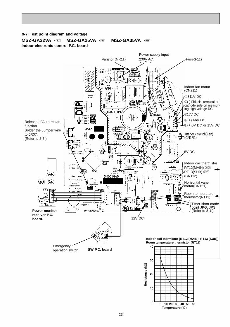
Indoor coil thermistor [RT12 (MAIN), RT13 (SUB)]Room temperature thermistor (RT11)
Temperature (:)
Res
ista
nce
(k"
)
MSZ-GA22VA - MSZ-GA25VA - MSZ-GA35VA -Indoor electronic control P .C. board
E1E1E1
Release of Auto restartfunctionSolder the Jumper wireto JR07.(Refer to 8-3.)
230V AC Fuse(F11)
Indoor coil thermistorRT12(MAIN) 12
RT13(SUB) 34
(CN112)
Horizontal vane motor(CN151)
9-7. Test point diagram and voltage
SW P.C. board
Power monitorreceiver P .C.board. 12V DC
5V DC
Interlock switch(Fan)(CN1R1)
Power supply input
Indoor fan motor(CN211)
}Varistor (NR11)
Room temperaturethermistor(RT11)
} Timer short modepoint JPG, JPS(Refer to 8-1.)
5(+)3-6V DC
415V DC
3(-) Fiducial terminal ofcathode side on measur-ing high-voltage DC
1311V DC
6(+)0V DC or 15V DC
Emergency operation switch
OB378_--1qxp 05.1.17 12:55 Page 23
24
DISASSEMBLY INSTRUCTIONS10
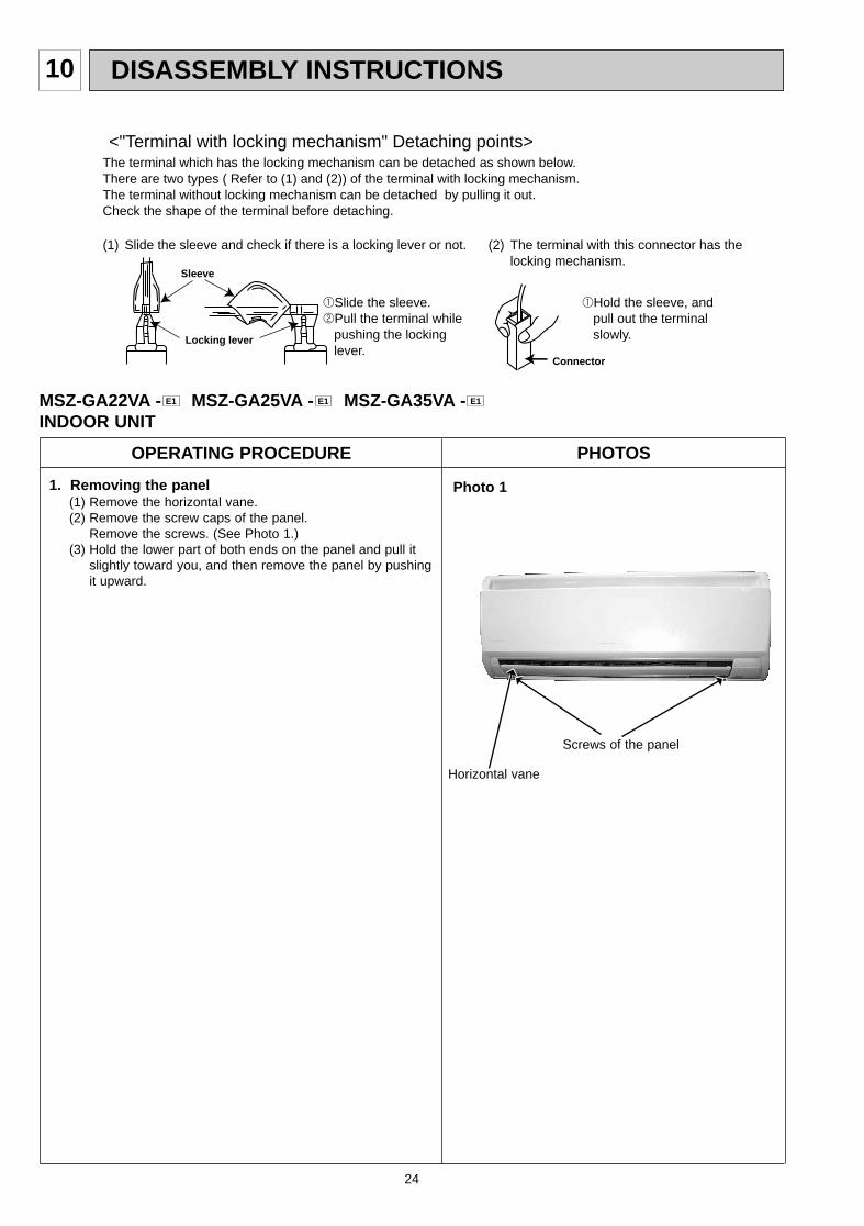
(1) Slide the sleeve and check if there is a locking lever or not. (2) The terminal with this connector has the locking mechanism.
1Slide the sleeve.2Pull the terminal while pushing the locking lever.
1Hold the sleeve, and pull out the terminal slowly.
The terminal which has the locking mechanism can be detached as shown below.There are two types ( Refer to (1) and (2)) of the terminal with locking mechanism.The terminal without locking mechanism can be detached by pulling it out.Check the shape of the terminal before detaching.
<"Terminal with locking mechanism" Detaching points>
Connector
Sleeve
Locking lever
MSZ-GA22VA - MSZ-GA25VA - MSZ-GA35VA -INDOOR UNIT
E1E1E1
OPERATING PROCEDURE PHOTOS
Photo 11. Removing the panel(1) Remove the horizontal vane. (2) Remove the screw caps of the panel.
Remove the screws. (See Photo 1.)(3) Hold the lower part of both ends on the panel and pull it
slightly toward you, and then remove the panel by pushing it upward.
Screws of the panel
Horizontal vane
OB378_--1qxp 05.1.17 12:55 Page 24
25
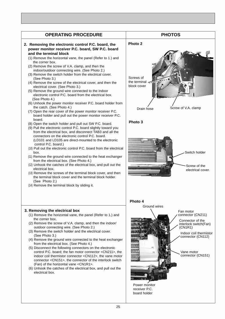
2. Removing the electronic control P .C. board, thepower monitor receiver P .C. board, SW P.C. boardand the terminal block(1) Remove the horizontal vane, the panel (Refer to 1.) and
the corner box. (2) Remove the screw of V.A. clamp, and then the
indoor/outdoor connecting wire. (See Photo 2.)(3) Remove the switch holder from the electrical cover.
(See Photo 3.)(4) Remove the screw of the electrical cover, and then the
electrical cover. (See Photo 3.)(5) Remove the ground wire connected to the indoor
electronic control P.C. board from the electrical box. (See Photo 4.)
(6) Unhook the power monitor receiver P.C. board holder from the catch. (See Photo 4.)
(7) Open the rear cover of the power monitor receiver P.C. board holder and pull out the power monitor receiver P.C. board.
(8) Open the switch holder and pull out SW P.C. board.(9) Pull the electronic control P.C. board slightly toward you
from the electrical box, and disconnect TAB3 and all the connectors on the electronic control P.C. board. (LD101 and LD105 are direct-mounted to the electronic control P.C. board.)
(10) Pull out the electronic control P.C. board from the electrical box.
(11) Remove the ground wire connected to the heat exchangerfrom the electrical box. (See Photo 4.)
(12) Unhook the catches of the electrical box, and pull out the electrical box.
(13) Remove the screws of the terminal block cover, and thenthe terminal block cover and the terminal block holder.(See Photo 2.)
(14) Remove the terminal block by sliding it.
OPERATING PROCEDURE PHOTOS
Screw of the electrical cover.
Switch holder
Photo 3
3. Removing the electrical box(1) Remove the horizontal vane, the panel (Refer to 1.) and
the corner box. (2) Remove the screw of V.A. clamp, and then the indoor/
outdoor connecting wire. (See Photo 2.)(3) Remove the switch holder and the electrical cover.
(See Photo 3.)(4) Remove the ground wire connected to the heat exchanger
from the electrical box. (See Photo 4.)(5) Disconnect the following connectors on the electronic
control P.C. board; the fan motor connector <CN211>, the indoor coil thermistor connector <CN112>, the vane motor connector <CN151>, the connector of the interlock switch (Fan) of the horizontal vane <CN1R1>.
(6) Unhook the catches of the electrical box, and pull out the electrical box.
Photo 4
Indoor coil thermistorconnector (CN112)
Fan motor connector (CN211)
Vane motor connector (CN151)
Ground wires
Photo 2
Screws of the terminalblock cover
Screw of V.A. clamp
Power monitor receiver P.C.board holder
Connector of the interlock switch(Fan)(CN1R1)
Drain hose
OB378_--1qxp 05.1.17 12:55 Page 25
26
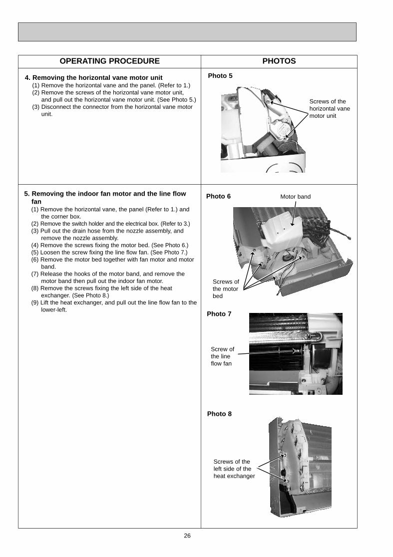
OPERATING PROCEDURE PHOTOS
Photo 6
Photo 8
Screws of theleft side of theheat exchanger
4. Removing the horizontal vane motor unit(1) Remove the horizontal vane and the panel. (Refer to 1.)(2) Remove the screws of the horizontal vane motor unit,
and pull out the horizontal vane motor unit. (See Photo 5.)(3) Disconnect the connector from the horizontal vane motor
unit.
Photo 5
5. Removing the indoor fan motor and the line flowfan (1) Remove the horizontal vane, the panel (Refer to 1.) and
the corner box. (2) Remove the switch holder and the electrical box. (Refer to 3.)(3) Pull out the drain hose from the nozzle assembly, and
remove the nozzle assembly.(4) Remove the screws fixing the motor bed. (See Photo 6.)(5) Loosen the screw fixing the line flow fan. (See Photo 7.)(6) Remove the motor bed together with fan motor and motor
band.(7) Release the hooks of the motor band, and remove the
motor band then pull out the indoor fan motor.(8) Remove the screws fixing the left side of the heat
exchanger. (See Photo 8.)(9) Lift the heat exchanger, and pull out the line flow fan to the
lower-left. Photo 7
Screw of the lineflow fan
Screws of the horizontal vane motor unit
Screws of the motorbed
Motor band
OB378_--1qxp 05.1.17 12:55 Page 26
27
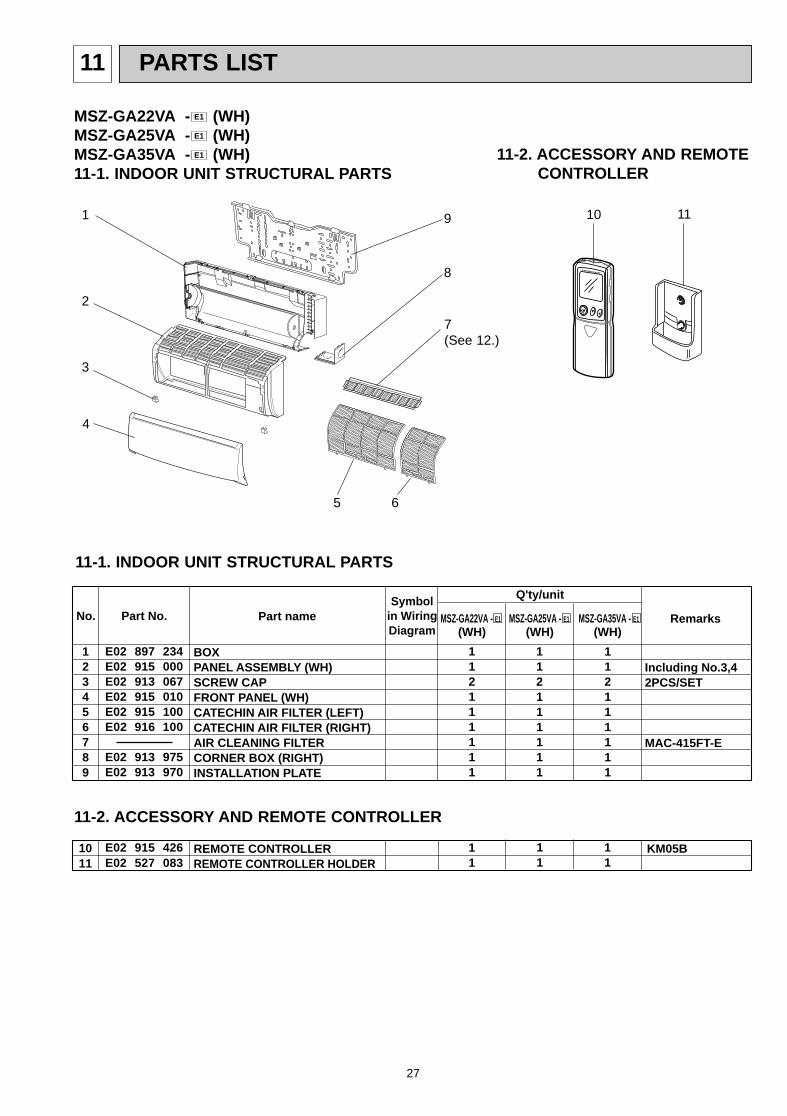
PARTS LIST11
MSZ-GA22VA - (WH)MSZ-GA25VA - (WH)MSZ-GA35VA - (WH)11-1. INDOOR UNIT STRUCTURAL PARTS
E1
E1
E1
No. Part No. Part name RemarksSymbol
in WiringDiagram
Q'ty/unit
123456789
MSZ-GA22VA - E1 MSZ-GA35VA - E1
1011
REMOTE CONTROLLERREMOTE CONTROLLER HOLDER
KM05B
BOXPANEL ASSEMBLY (WH)SCREW CAPFRONT PANEL (WH)CATECHIN AIR FILTER (LEFT)CATECHIN AIR FILTER (RIGHT)AIR CLEANING FILTERCORNER BOX (RIGHT)INSTALLATION PLATE
Including No.3,42PCS/SET
MAC-415FT-E
(WH) (WH)
112111111
112111111
E02 897 234E02 915 000E02 913 067E02 915 010E02 915 100E02 916 100
E02 913 975E02 913 970
11
E02 915 426E02 527 083
112111111
11
11
MSZ-GA25VA - E1
(WH)
11-1. INDOOR UNIT STRUCTURAL PARTS
11-2. ACCESSORY AND REMOTECONTROLLER
1
8
2
4
3
9
5 6
1110
11-2. ACCESSORY AND REMOTE CONTROLLER
7(See 12.)
OB378_--1qxp 05.1.17 12:55 Page 27
28
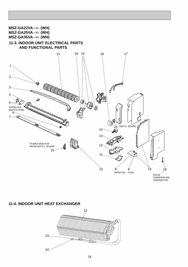
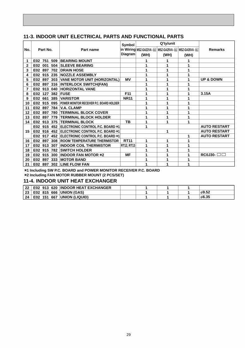
11-3. INDOOR UNIT ELECTRICAL PARTS AND FUNCTIONAL PARTS
MSZ-GA22VA - (WH)MSZ-GA25VA - (WH)MSZ-GA35VA - (WH)E1
E1
E1
4
2
5
3
9
ROOM TEMPERATURE THERMISTOR
VARISTOR
1
6
22
11-4. INDOOR UNIT HEAT EXCHANGER
10 8
7
12
13
14
POWER MONITOR RECEIVER P.C. BOARD
FUSE
15
16
SW P.C. BOARD
21
INTERLOCKSWITCH (FAN)
24
23
11
15
15
19 171820
OB378_--1qxp 05.1.17 12:55 Page 28
29
BEARING MOUNTSLEEVE BEARINGDRAIN HOSENOZZLE ASSEMBLYVANE MOTOR UNIT (HORIZONTAL)INTERLOCK SWITCH(FAN)HORIZONTAL VANEFUSEVARISTORPOWER MONITOR RECEIVER P.C. BOARD HOLDERV.A. CLAMPTERMINAL BLOCK COVERTERMINAL BLOCK HOLDERTERMINAL BLOCKELECTRONIC CONTROL P.C. BOARD W1ELECTRONIC CONTROL P.C. BOARD W1ELECTRONIC CONTROL P.C. BOARD W1ROOM TEMPERATURE THERMISTORINDOOR COIL THERMISTORSWITCH HOLDERINDOOR FAN MOTOR W2MOTOR BANDLINE FLOW FAN
UP & DOWN
3.15A
AUTO RESTARTAUTO RESTARTAUTO RESTART
RC0J30-
MV
F11NR11
TB
RT11RT12, RT13
MF
(WH) (WH)No. Part No. Part name Remarks
Symbolin WiringDiagram
Q'ty/unit
1234567891011121314
15
161718192021
222324
INDOOR HEAT EXCHANGERUNION (GAS)UNION (LIQUID)
{9.52{6.35
E02 751 509E02 001 504 E02 897 702E02 915 235E02 897 303E02 897 316E02 913 040E02 127 382E02 661 385 E02 915 095E02 897 784E02 897 780E02 897 779E02 913 375E02 915 452E02 916 452E02 917 452E02 897 308E02 913 307E02 915 782E02 915 300E02 897 333E02 897 302
111111111111111
111111
11111111111111
1111111
E02 913 620E02 815 666E02 151 667
111
111
W1 Including SW P.C. BOARD and POWER MONITOR RECEIVER P.C. BOARDW2 Including FAN MOTOR RUBBER MOUNT (2 PCS/SET)
MSZ-GA22VA - E1 MSZ-GA25VA - E1 MSZ-GA35VA - E1
(WH)
11111111111111
1
111111
111
11-3. INDOOR UNIT ELECTRICAL PARTS AND FUNCTIONAL PARTS
11-4. INDOOR UNIT HEAT EXCHANGER
OB378_--1qxp 05.1.17 12:55 Page 29
30
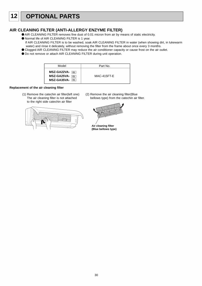
12 OPTIONAL PARTS
Model Part No.
E1
E1 MAC-415FT-EMSZ-GA22VA-MSZ-GA25VA-MSZ-GA35VA- E1
Air cleaning filter(Blue bellows type)
(1) Remove the catechin air filter(left one)The air cleaning filter is not attachedto the right side catechin air filter
(2) Remove the air cleaning filter(Bluebellows type) from the catechin air filter.
Replacement of the air cleaning filter
AIR CLEANING FIL TER (ANTI-ALLERGY ENZYME FILTER)● AIR CLEANING FILTER removes fine dust of 0.01 micron from air by means of static electricity.● Normal life of AIR CLEANING FILTER is 1 year.
If AIR CLEANING FILTER is to be washed, soak AIR CLEANING FILTER in water (when showing dirt, in lukewarm water) and rinse it delicately, without removing the filter from the frame about once every 3 months.
● Clogged AIR CLEANING FILTER may reduce the air conditioner capacity or cause frost on the air outlet.● Do not remove or attach AIR CLEANING FILTER during unit operation.
OB378_--1qxp 05.1.17 12:55 Page 30

31
OB378_--1qxp 05.1.17 12:55 Page 31

HEAD OFFICE: MITSUBISHI DENKI BLDG., 2-2-3, MARUNOUCHI, CHIYODA-KU, TOKYO100-8310, JAPAN
CC Copyright 2005 MITSUBISHI ELECTRIC ENGINEERING CO.,L TDDistributed in Jan. 2005. No. OB378 6Made in Japan
New publication, effective Jan. 2005Specifications subject to change without notice.
OB378_--1qxp 05.1.17 12:55 Page 32