Embed Size (px)
Citation preview

SPONGE IRON PRODUCTION FROM ORE -COAL COMPOSITE PELLETS IN TUNNEL KILN
S.C.Khattoi1* , G. G. Roy2
1 Project & Engineering Consultancy, Keonjhar, Odisha, India 2 Indian Institute of Technology, Kharagpur – 721302, India
Abstract: Today India stands as the largest producer of coal based sponge iron through
rotary kiln process using calibrated ore and non coking coal. However, Rotary kiln process
suffers from serious limitations like low productivity and pollution. In this respect fixed bed
Tunnel kiln furnace are evolving as an alternative to Rotary kiln process. Iron ore fines and
the low grade beneficiated iron ore cake are directly used for manufacturing of sponge iron
in tunnel kilns. The material bed in Tunnel kiln being stationary, it does not require high
strength and thermal stability of the raw material. This gives the opportunity for charging
composite pellets or briquettes which could possibly enhance kiln productivity and efficiency.
In order to explore the efficacy of iron ore-coal composite pellets over indurated iron ore
pellets, standard charging of concentric layers of separate iron ore, coal fines, or their
mixture, these pellets were tested at 1200oC in the tunnel kiln. It was observed that
metallization for indurated iron ore pellets, and concentric charging were limited to 80% to
83% where as composite pellets had a metallic iron of 88% to 89%. Thermal efficiency of
tunnel kiln is quiet low and depends on the length of the kiln. Present experiment show that
use of composite pellets in the present kiln could improve the thermal efficiency from 27%
with standard practice to 37% with composite pellets. Similarly, carbon utilization efficiency
could be increased from 48% with standard practice to 65% with composite pellets.
Keywords: Tunnel Kiln, Iron ore-coal composite pellets, Sponge iron, Thermal efficiency,
Carbon utilization efficiency, Percentage metallic iron
1. INTRODUCTION
The tunnel kilns are mostly used by the ceramic industries for heating refractory and ceramic products [1-2]. In the year 1908 use of tunnel kiln started for iron oxide reduction. This process was invented by E.Sieurin as Hoganas process [3]. In 1954, more kilns came in operation in SWEDEN and USA. Presently it is more popular in China for sponge iron production from beneficiated iron ore fines cakes. In this process, the material passes through different temperature regimes of preheating, and reduction as in BF but with stationary bed of material. Therefore, one has the flexibility with raw material. The product quality is very
good, and so the process finds application in reduction of Ferro-nickels, Ilmenite etc [4]. Another major advantage is that it utilizes beneficiated fines directly without induration. Investment and maintenance is low. Since it is gas based process, it is also environmentally clean. Unlike rotary kiln, heating is external and therefore it permits the use of different carbon source for heating and reduction. The only drawback of this process is low productivity which is even less compared to rotary kiln. Therefore, in the present study attempt has been made to improve the productivity by using iron ore-coal composite pellets. Laboratory investigations [5] and industrial applications [6] have already proved the potential use of composite pellets.
A tunnel kiln is a long stationary insulated furnace made of refractory bricks or pressed ceramic wool blankets. It has a rail track provision inside the kiln for the travel of trolleys. The material is loaded on the trolleys and enters from the feed end of the tunnel kiln. It comes out on the other end by travelling inside the kiln with a prefixed speed. The kiln has three different zones called pre heat zone (warm up), firing zone (deoxidize) and cooling zone shown in the Fig. 1. The trolley is pushed by the help of a hydraulic pusher. The length of each zone is designed considering the trolley speed and retention time required in those zones as per the process requirement. A sand seal provided along the entire length of the kiln to prevent the flue gas leakage to the bottom of the trolley. The heating of the furnace is done by coal gas called producer gas. The producer gas is burnt in the firing zone through number of gas burners. Producer gas being clean, no pollution control equipment is used in the exhaust system. The cooling of the material on the trolley is done by indirect air cooling in the first part and direct air cooling in the last part. Some kilns use water jacket as indirect cooling in the first part in place of air jacket in order to enhance cooling. The heat carried by the flue gas is recovered through the heat exchanger and hot air from heat exchanger is used for gas burners. The heat from the cooling zone is recovered directly from the twin wall air jacket and used for drying of feed material to make it free flowing for filling the container from its respective hoppers. The beauty of this process is that the heating coal is separate from the reduction coal and it can be from a different source. There is no tumbling of material inside the kiln so high strength for pellet is not required and no dust is generated. The post combustion of the CO gas that comes out of the container generates heat and reduces producer gas consumption. The total reaction is done as a compact bed inside the sagger. The actual view of a tunnel kiln is shown in Fig. 2, where a trolley carrying the silicon carbide containers called as saggers is entering the kiln. Since the kiln end is open that makes it difficult to control the reduction atmosphere inside the kiln, the material is filled inside the saggers to maintain the desired atmosphere for reaction. A thick layer of carbon bearing material is filled at the top of the container to prevent the re oxidation of product at the time of cooling.
2. EXPERIMENTAL
Some intended experiments are made in the industrial tunnel kiln by introducing few specially designed saggers filled with pellets along with the standard saggers. The usual steps involved in the process are briefly described below along with the specially designed experiments. The process flow sheet for iron oxide pellet, briquette, and fines is given in Fig. 3.Tunnel Kiln used in the present study is a 49.5 meter tunnel having 14.7meter as pre heat zone, 9.1meter as firing zone and 25.7meter as cooling zone. It has 8 gas burners positioned equally on both side walls in the firing zone. They are long flame burners and
heating is done from both sides of the saggers mounted on the moving trolleys. The firing zone with the burners is 9.1 meter and the retention time in this high temperature zone for reduction is 16 hours. The kiln is made of insulating ceramic wool blanket blocks. There are 4 thermocouples in the pre heat zone, 5 thermocouples in the cooling zone and 8 thermocouples in the firing zone. All the 13 thermocouples are mounted from furnace top, except 2 numbers each mounted in the left and right side of the firing zone. The temperature in preheat zone is maintained in an decreasing order from firing zone to feed end due to flow of hot gas from firing zone to feed end. The trolley carrying saggers moves from feed end to firing zone there by absorbs the heat from the hot gas in a counter current process. The firing zone is maintained between 1150°C to 1200°C. The temperature at the end of cooling zone is maintained less than 200 °C by air cooling. Usually, Iron ore fines and coal fines are introduced into the saggers in the form of separate concentric cylinders for reduction. The iron ore fines forms a hollow cylinder at the middle of the sagger and its outer surface and core is filled with coal fines as shown in Fig 4. The loaded saggers on the trolley enter the tunnel kiln for processing. In the present study some composite pellets are made from iron ore fines and coal fines and those pellets are put into special containers for studying the reduction kinetics of it under tunnel kiln conditions. Iron ore fines of 0 - 5mm with specific chemical composition as given in Table 1, is collected from different mines from Joda, Keonjhar, Odissa. Anthracite coal and South African coal is collected from imported sources. Indian coal from central coal field (Jharkhand) and Mohanadi coal field (Odisha) is collected from the mines. Coal proximate analysis is displayed in the Table 2. Iron ore fines and Anthracite coal fines are subjected to grinding in a small ball mill to produce its powder of less than 150 microns for making pellets. Anthracite coal is mixed in the ratio varying from 3% to 6% by weight to iron ore fines for making composite pellet or cylinder along with inorganic binder. The ore fines, anthracite coal and bentonite is mixed thoroughly with the help of a mixture machine and then the mixture is shifted to the pelletizing disc to produce + 8mm to – 16mm pellet. Some quantity of green pellet and fired pellet are also made without the internal anthracite coal for comparison against pellets with internal coal. All the different samples are loaded in separate containers with a mark for identifying them after reduction and metallization study. Coal from all the other mines is crushed to -3mm size for use as external coal with pellets while charging in the containers. For composite pellets amount of external coal is calculated in addition to internal carbon so as to compensate for the required carbon for reduction and for protection of the product against re-oxidation. Same size, i.e. -3mm dolomite is also mixed along with the external coal to prevent the increase of sulphur in the reduced iron. The quantity of dolomite used is maximum 9% by weight of the iron oxide. The thermal efficiency of gasifier coal is high with 50 to 55% FC and 27 to 30% VM. Reduction coal is not considered for thermal efficiency but for higher reactivity. Internal coal is considered for low ash and higher carbon as it will remain inside the pellet even after reduction Normally the saggers are filled either in the automatic loading system or semi automatic system. However, for our test purpose, the test saggers are filled manually and marked. The saggers are loaded on the trolleys along with other saggers which are subjected to the same temperature and time. The main test is conducted in silicon carbide saggers. To compare the heat transfer efficacy of other container material, clay saggers are used in the same trolley along with the silicon carbide saggers. The final reduced iron is checked in all marked containers for comparison. Each trolley is pushed in a pre decided time interval so as to maintain the desired residence time in each zone. The reduction reaction gets completed inside the sagger in the high temperature zone. At the discharge end the material from all the saggers is pneumatically sucked by a suction pump and it passes through a cyclonic separator
to take out the heavier particles. The finer particles carried by the same air is filtered in a bag filter unit and the clean air is discharged to the atmosphere. The collected material from the cyclone is further processed to remove the un-burnt coal char and ash from the main product through magnetic separator. The product sponge iron being hydroscopic in nature, it is preserved in a close area like bins, silos or they are properly packed in polythene bags. In the present case, for different analysis purpose the material is manually unloaded from the saggers by tilting it on the collecting floor.
3. RESULTS
3.1 Comparison of different systems studied
Seven different material systems including composite pellets were studied in the tunnel kiln, by separately loading material in different containers in the same experimental run. These material systems are: i) Standard concentric layer charging: It follows the standard practice of material loading in tunnel kiln where the iron ore fines is put in the form of thin cylindrical layer (50 mm) sandwiched between two concentric layers of coal fines. ii) Green pellets: here pellets of iron ore, naturally indurate by air drying for 4 days are used. Green pellets are charged along with external coal into the container. iii) Indurated pellets: here pellets of iron ore, indurated at 1250oC for 2 hours, are charged along with external coal in the container. iv) Iron ore-coal mixture: here iron ore fines of comparatively bigger size (2-5mm) are mixed with coal fines and charged in the container. Such system avoids extra cost associated with grinding of ore particles to fine powder (<150μm) for making composite pellets. v) Composite layer: here iron ore coal mixture is used as thin cylindrical layer sandwiched between coal layers, as in the standard practice of tunnel kiln. vi) Composite pellets: here iron ore fines (<150 μm) and coal fines (<150 μm and 6% of the iron ore used) mixture are pelletized and indurated by air drying for 4 days before use. The pellets are charged in the container along with external coal. In all the above systems, tests are conducted with the iron ore containing 64% Fe, anthracite coal with 85% fixed carbon (FC) as internal coal, bituminous coal with 48% FC as external coal, bentonite as binder and dolomite as desulphuriser for external coal. The test is conducted at 1200°C kiln temperature and each trolley is pushed in 1.5 hours. Total time from feed to discharge is 43.5 hours. The photographs of reduced composite cylinder and composite pellets are shown in Fig. 5.
The performance of the experiment was judged through three parameters: i) percentage metallic iron (%Fe(M)) produced, ii) carbon efficiency, iii) energy efficiency. Percentage metallic iron is represented in terms of total metallic iron formed as a fraction of total sponge product. Carbon efficiency is measured as a ratio of stoichiometric carbon required for the achieved %Fe(M) to the total carbon consumed. The thermal efficiency is measured as the minimum theoretical heat required for the achieved %Fe(M) to that of the actual heat absorbed.
The comparison of the seven material systems, are presented in Table 3. It is observed that the %Fe (M) is highest for the composite pellets (89%), followed by composite layer (85%) and lowest being for the standard concentric layer charging (80%). Green and fired pellets showed similar metallization (83%). Ore coal mixture is found to be inferior to green and fired pellets. While comparing the carbon efficiency; composite pellets again shows superiority with 65%, followed by ore coal mixture (62%), and the lowest being for the standard concentric layer charging (48%). All other three systems show similar behaviour with 51-53%. It is also observed that the thermal efficiency of composite pellets is again
highest (37%) among all the system studied, followed by ore coal mixture (34%), and lowest being the standard concentric layer charging (27%). All other systems show 29% thermal efficiency.
3.2 Effect of internal carbon
After seeing the definite edge of composite pellets over all other material systems in tunnel kiln, the partitioning of total added carbon as internal and external coal to composite pellets is studied and optimized. The effect of internal coal on %Fe(M) of reduced pellet is presented in Table 4. It is seen that %Fe(M) attain maximum at 5.1 % of internal carbon, and then decreases with increase in internal carbon. The Table also includes the data to show the similar effect for two different particle sizes. It is observed that both the particles show the similar trend of %Fe(M) with internal carbon, which passes through a maximum at 5.1% internal carbon. It is observed that for the same internal carbon of 5.1%, sample 1 that is made from fine particle (149 microns) show higher %Fe(M) (83%) than sample 2 made from comparatively bigger, 0-2mm particles (81%).
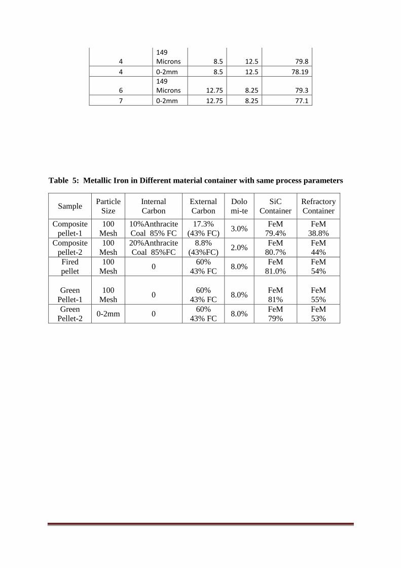
3.3 Effect of containers and various pellets
The rate of reduction of the material inside the container depends significantly on the steady state heat flux through the container. Therefore, effect of material of the container on the reduction kinetics of iron ore has been studied using two kinds of containers, namely silicon carbide (SiC) and fire clay refractory containers. Some cases of reduction with same process parameters, but with different container materials are presented in Table 5. It is noticed that with same temperature and time the reduction of all samples like composite pellet, green pellet, fired pellet etc. shows significantly higher %Fe(M) in SiC container compared to that in the refractory container. The effect is most significant in case of composite pellet-1, where the jump is greater than 200% (39 to 80%). The above effect is also depicted in Fig. 6, through a bar diagram.
SiC container having higher thermal diffusivity will offer much lesser time for heat penetration than refractory container. The reference time, defined as α/2Ttr = , where T is the thickness of the container and α is the thermal diffusivity, is calculated as 3.56 sec for silicon carbide container, while that for clay refractory is 7.5 sec. This indicates that heat moves through SiC container at a speed approximately twice that through the clay refractory container. Since such reduction process is heat transfer controlled, SiC container exposed to same time and temperature with same quality and quantity of material will produce metallic iron at a speed approximately twice than that of the clay refractory container. This is reflected in experimental data where %Fe(M) formed with SiC container is twice than that obtained with clay container.
3.4 Product quality
The sponge iron produced contains 80-90% metallic iron depending on the type of materials charged as mentioned in Table-3. The gangue in the sponge iron include unreduced iron oxide, sulphur, SiO2 and Al2O3. The source of sulphur in composite reduced pellet is internal coal. The sulphur content in the composite reduced pellets containing 6% internal anthracite coal is limited to 0.004% to 0.005%. Sources of SiO2 and Al2O3 are iron ore as well as internal coal in case of composite pellet. Conventional tunnel kiln processes do not use internal carbon with the iron oxide powder. So the silica and alumina remains the same in the product but the percentage goes up due to the loss of oxygen from iron oxide. With
composite agglomerate, the internal coal used is 5% to 6% of iron fines weight. The internal coal has ash of 6.0% and VM 9.0%. The additional silica and alumina in the reduced composite pellet due to the internal ash from the coal is 0.36% more than traditional tunnel kiln product. The SiO2 and Al2O3 in reduced composite pellet is 5.27% and 4.38% in comparison to traditional tunnel kiln having 5.0% and 4.29%.
3.5 Discussion
The reduction of iron oxide as lump or indurated pellet by CO depends on many factors like size, porosity, chemical composition. The topochemical reaction proceeds from top surface to the core forming Fe, FeO, Fe3O4 and Fe2O3 in concentric layers. Reaction time for converting all oxide to metallic iron is more dependent on the particle size. In case of a composite pellet the carbon is available in the close proximity of the iron oxide particle and the reduction reaction starts simultaneously inside the pellet once it attains the required temperature. A situation can be visualized where numerous fine iron ore particles undergoes such topochemical reaction parallel at several sites within the composite pellet. This has been depicted in Fig. 7. Such numerous simultaneous reactions enhance the kinetics significantly compared to iron ore pellets where a single topochemical reaction progress through the pellet.
Utilization of carbon in terms of CO utilization for reduction for three different bed mixture is depicted in Fig.8. The left section in Fig.8 shows the standard loading pattern of iron ore powder as 50mm thick cylindrical layer and coal fines as concentric cylindrical layers that is filled at the centre and outside of the iron layer. Since the cylinder is heated across the surface, CO is generated from all heights at similar rates and moves upward. Obviously, the CO gas that is generated at the top has lower residence time and hardly gets chance to acquire one more oxygen atom from iron ore for complete utilization of carbon to CO2. The CO gas that is also generated at the bottom of the container will mostly rise up through the coal bed, except the fraction that moves in transverse direction under concentration gradient inside the ore for further reduction. The situation is almost similar in case of concentric composite layers (middle section of Fig. 8). In this case CO is also generated inside the composite layers, which will undergo more interaction with iron ore during its rise yielding better utilization of carbon. The right section of Fig. 8, represents a bed of composite pellets. Here, during the rise of CO gas, it interacts with several pellets and participate in further reduction. The CO that is generated inside the pellets also gets several interactions with numerous fine iron ore particles inside the pellet and get utilized. Therefore, both the internal and external coal gets better utilized in a bed of composite pellets. This is reflected in terms of higher metallization and carbon utilization efficiency for composite pellets. Heat is also generated inside the bed through burning of CO using ore oxygen that increases the thermal efficiency.
4. CONCLUSION
Reduction of iron ore coal composite pellets in Tunnel kiln has been found to emerge with an edge over ordinary green, indurated pellets as well as standard charging of iron ore in the form of thin concentric layers of iron ore and coal fines, or their mixture. Performance parameters like percentage metallic iron formed, carbon utilization efficiency, thermal efficiency have been found to be significantly higher for composite pellets over other pellets and concentric layer charging of iron ore and coal fines, or their mixtures. The materials of
the container have also found to have significant effect on the reduction kinetics. Silicon carbide container has emerged much superior compared to conventionally used ceramic (fire clay) containers.
5. References
1. A. I. Kokunov, M. G. Naidis, P. I. Berenshtein, and G. I. Kochin: Stekloi Keramika, 1977, No. 11, pp. 36-37
2. M. Z. Shvartsman, G. A. Ketslakh, I. T. Gubko, G. V. Orlov, M. Z. Naginskii, G. A. Shubin, I. P. Tsibin, A. B. Bryzgalov, A. K. Grachev, and S. M. Kolkin: Ogneupory, 1980, No. 9, pp. 16-23.
3. G. S. Upadhyay: Powder Metallurgy Technology, Cambridge International Science Publishing, England, 2002
4. “Selective recovery of titanium dioxide from low grade sources”: http://www.saimm.co.za/Journal/v111n03p173a.txt
5. Donskoi, E., McElwain, D. L. S., and Wibberley, L. J., Estimation and Modelling of Parameters for Direct Reduction in Iron Ore/Coal Composite: Part II. Kinetics Parameters, Metallurgical and Materials Transaction B, 34B, 255-266, 2003 6. Chatterjee, A., Sponge Iron Production by Direct Reduction of Iron Oxide, Prentice Hall of India Pvt. Ltd., New Delhi, 2010.
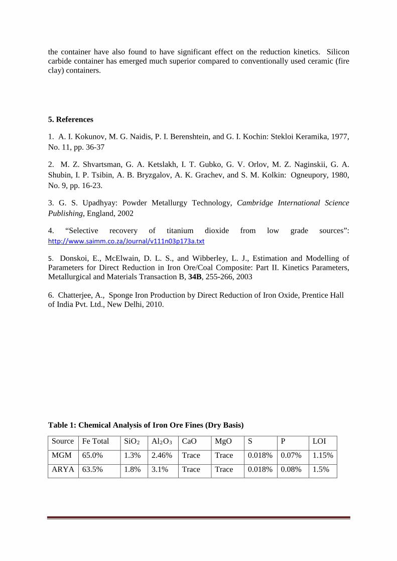
Table 1: Chemical Analysis of Iron Ore Fines (Dry Basis)
Source Fe Total SiO2 Al2O3 CaO MgO S P LOI
MGM 65.0% 1.3% 2.46% Trace Trace 0.018% 0.07% 1.15%
ARYA 63.5% 1.8% 3.1% Trace Trace 0.018% 0.08% 1.5%
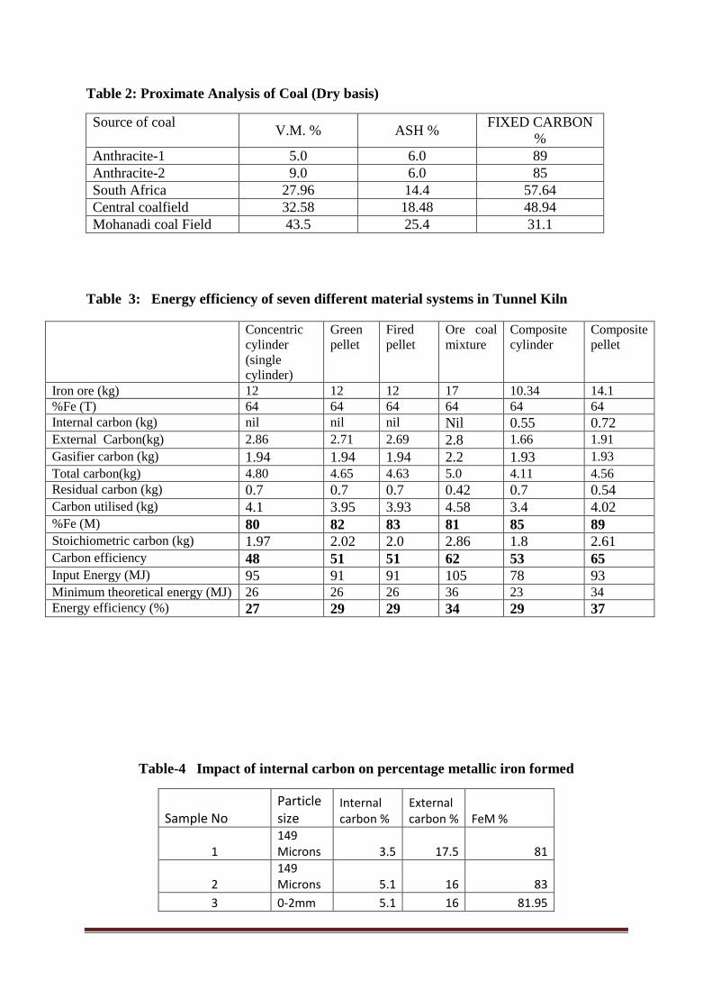
Table 2: Proximate Analysis of Coal (Dry basis)
Source of coal V.M. % ASH % FIXED CARBON %
Anthracite-1 5.0 6.0 89 Anthracite-2 9.0 6.0 85 South Africa 27.96 14.4 57.64 Central coalfield 32.58 18.48 48.94 Mohanadi coal Field 43.5 25.4 31.1
Table 3: Energy efficiency of seven different material systems in Tunnel Kiln
Concentric cylinder (single cylinder)
Green pellet
Fired pellet
Ore coal mixture
Composite cylinder
Composite pellet
Iron ore (kg) 12 12 12 17 10.34 14.1 %Fe (T) 64 64 64 64 64 64 Internal carbon (kg) nil nil nil Nil 0.55 0.72 External Carbon(kg) 2.86 2.71 2.69 2.8 1.66 1.91 Gasifier carbon (kg) 1.94 1.94 1.94 2.2 1.93 1.93 Total carbon(kg) 4.80 4.65 4.63 5.0 4.11 4.56 Residual carbon (kg) 0.7 0.7 0.7 0.42 0.7 0.54 Carbon utilised (kg) 4.1 3.95 3.93 4.58 3.4 4.02 %Fe (M) 80 82 83 81 85 89 Stoichiometric carbon (kg) 1.97 2.02 2.0 2.86 1.8 2.61 Carbon efficiency 48 51 51 62 53 65 Input Energy (MJ) 95 91 91 105 78 93 Minimum theoretical energy (MJ) 26 26 26 36 23 34 Energy efficiency (%) 27 29 29 34 29 37
Table-4 Impact of internal carbon on percentage metallic iron formed
Sample No Particle size
Internal carbon %
External carbon % FeM %
1 149 Microns 3.5 17.5 81
2 149 Microns 5.1 16 83
3 0-2mm 5.1 16 81.95
4 149 Microns 8.5 12.5 79.8
4 0-2mm 8.5 12.5 78.19
6 149 Microns 12.75 8.25 79.3
7 0-2mm 12.75 8.25 77.1
Table 5: Metallic Iron in Different material container with same process parameters
Sample Particle Size
Internal Carbon
External Carbon
Dolomi-te
SiC Container
Refractory Container
Composite pellet-1
100 Mesh
10%Anthracite Coal 85% FC
17.3% (43% FC) 3.0% FeM
79.4% FeM
38.8% Composite
pellet-2 100
Mesh 20%Anthracite Coal 85%FC
8.8% (43%FC) 2.0% FeM
80.7% FeM 44%
Fired pellet
100 Mesh 0 60%
43% FC 8.0% FeM 81.0%
FeM 54%
Green
Pellet-1
100
Mesh
0
60%
43% FC
8.0%
FeM 81%
FeM 55%
Green Pellet-2 0-2mm 0 60%
43% FC 8.0% FeM 79%
FeM 53%
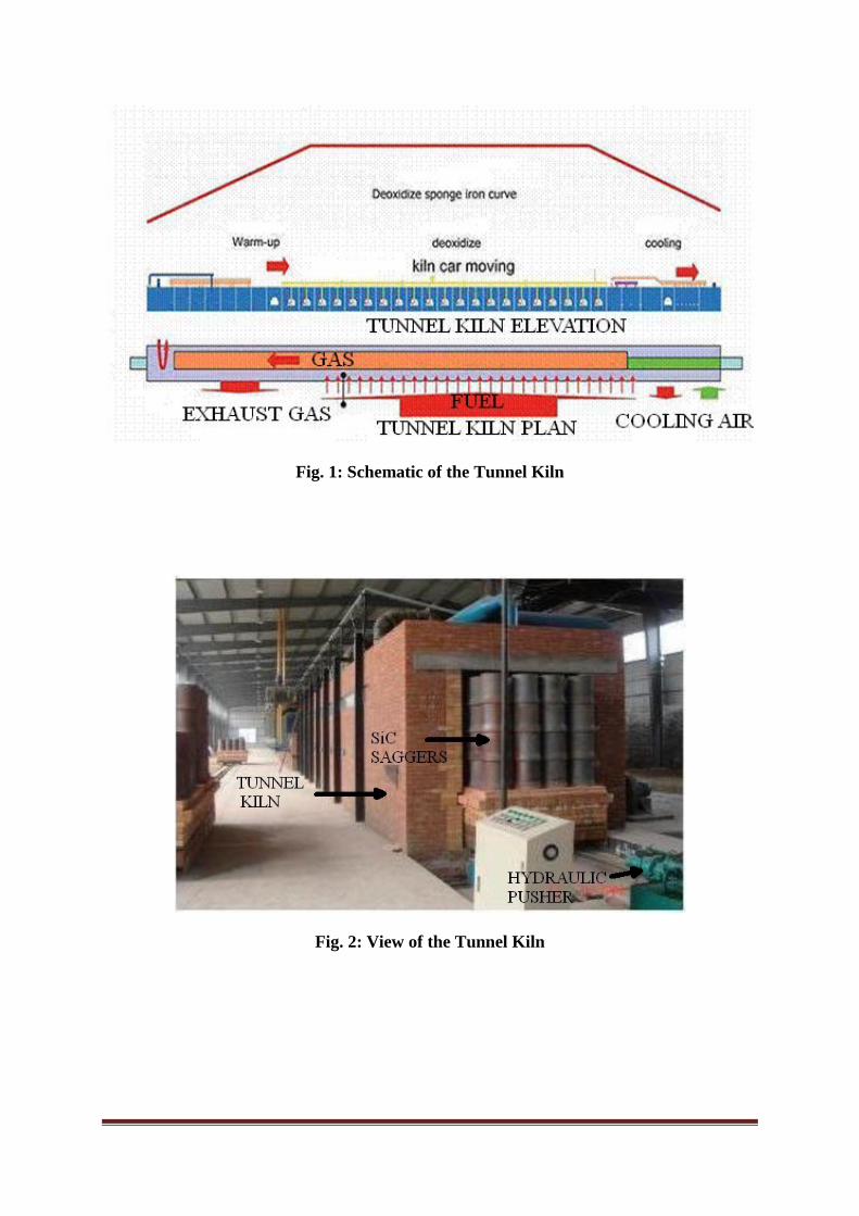
Fig. 1: Schematic of the Tunnel Kiln
Fig. 2: View of the Tunnel Kiln
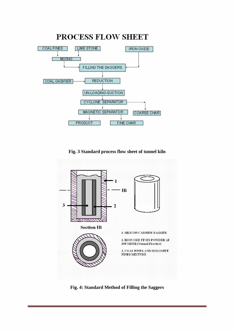
Fig. 3 Standard process flow sheet of tunnel kiln
Fig. 4: Standard Method of Filling the Saggers

Reduced composite cylinder Reduced composite pellets
Fig.5 Photographs of reduced composite pellet, composite cylindre from tunnel kiln
Fig. 6: Metallic iron formation in different containers
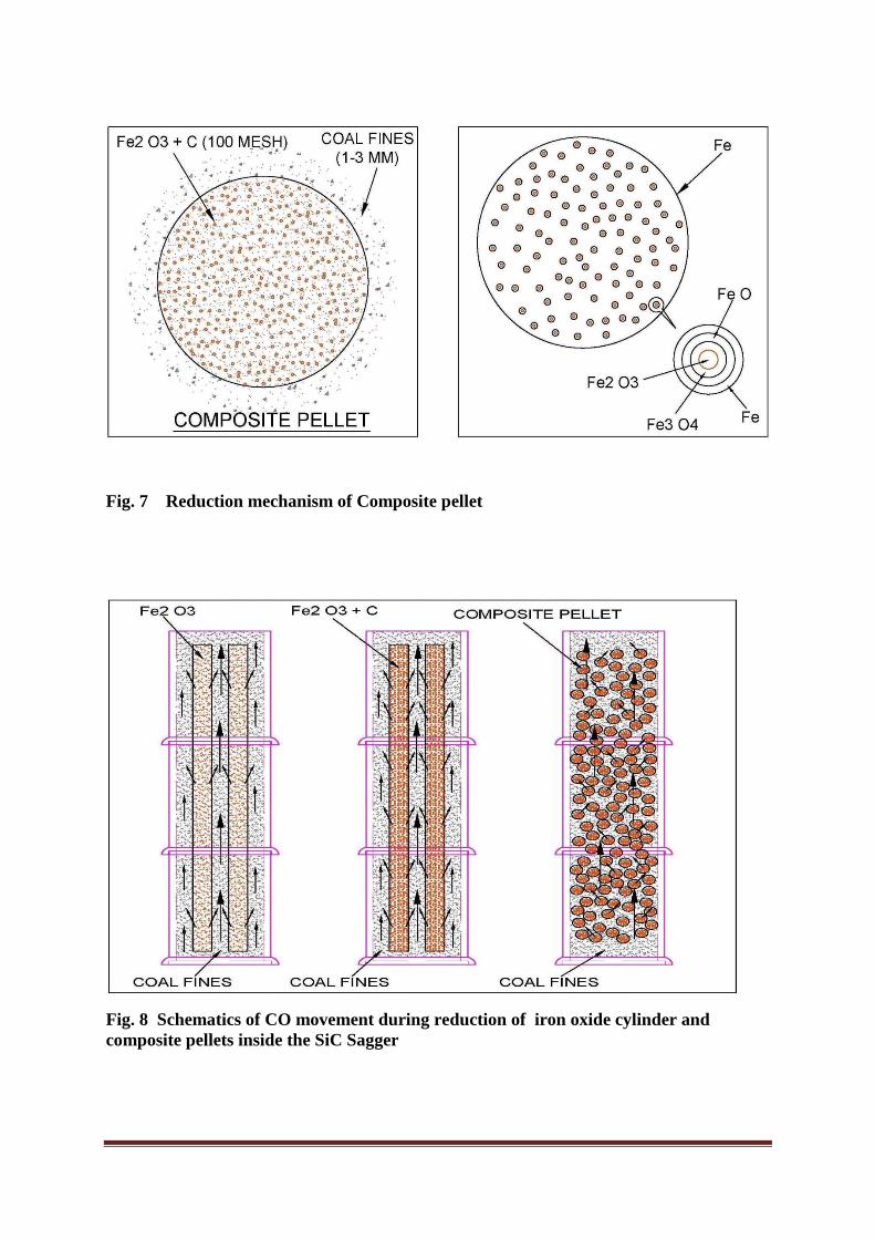
Fig. 7 Reduction mechanism of Composite pellet
Fig. 8 Schematics of CO movement during reduction of iron oxide cylinder and composite pellets inside the SiC Sagger