Embed Size (px)
Citation preview

Operator’s & Parts Manual
“Spray Shield” Directed Sprayer“Shield Max” Hooded Sprayer
Printed In The USA — Specifications & Design Subject To Change Without Notice! 5-10-07 00-014R2
This is a limited warranty. It covers products manufactured by WYLIE Mfg. Co. The Warrantor is WYLIE Mfg. Co., 702 E. 40th St., Lubbock, TX 79404 USA. The duration of the warranty for WYLIE manufactured equipment and products (excluding polyethylene tanks) is for one year from date of delivery to the carrier. The Warrantor warrants to the Buyer that the product(s) sold hereunder are free from defects to material and workmanship, under normal use and service, in the hands of the original buyer.
If goods are defective, the defective goods will be replaced with identical goods. If identical goods are not available, the Buyer may elect to receive a refund of the purchase price for the defective goods, or the Buyer may order similar goods. The damage for defective goods shall not exceed the purchase price of the defective goods. No allowance shall be made for labor or expense or repairing goods without prior approval in writing by the Warrantor. The Buyer’s remedy under this warranty does not include incidental or consequential damages.
For products not manufactured by the Warrantor, the Warrantor warrants these products to the extent of the warranties of their respective manufactures. There are no warranties which extend beyond this limited warranty, including the implied warranty of merchantability. Dealers or representatives shall not make any representation in regard to particular goods except as authorized by the Warrantor through a written warranty accompanying those particular goods.
WYLIE Mfg. Co., and its divisions, “Wylie Spray Centers,” in each location, requires as a condition of sale and coverage by its LIMITED WARRANTY that all equipment sold by it be used in accordance with the instructions and specifications of the Warrantor. This requirement is in addition to the LIMITED WARRANTY.
Polyethylene and fiberglass tanks – These tanks are warranted for the storage and transport of water, herbicide solutions (on farm), liquid fertilizer and liquid feed. Such tanks should not be used for the storage of any bulk herbicide (undiluted). Any such use will render this warranty void.
In addition, the Warrantor makes no warranty with regard to bulkhead tank fittings used in connection with tanks containing bulk herbicides and the use of any such fittings sold by the Warrantor or any WYLIE dealer in connection with tanks containing bulk herbicides is improper.
Chemical Incompatibility – The Warrantor does not make any recommendations or warranties regarding chemical compatibility. WYLIE shall not be liable for any damages due to chemical incompatibility, and any Buyer or user should rely solely on written information furnished by the chemical manufacturer regarding chemical compatibility.
No employee of WYLIE Mfg. Co., or its representatives, agents or dealers, is authorized to vary the terms of this limited warranty.
This equipment was carefully designed and manufactured to give you dependable service. To insure efficient operation of this equipment, please read this operator’s manual carefully. Check each item and acquaint yourself with the adjustments required to maintain optimum performance and operation. Remember, this equipment’s performance depends on how you operate and care for it!
At the end of each season, thoroughly clean and inspect your equipment. Preventive maintenance saves time and pays dividends. Your nearest Wylie Spray Center has original equipment parts which assure proper fit and best performance. Record your equipment’s model and serial numbers and the date you purchased this equipment in the space below. Have this information available when you order parts or attachments.
Model Number:
Serial Number:
Date Purchased:
A Message To The Owner And Operator
Limited Warranty
Disclaimer of Warranty
Warranty Information
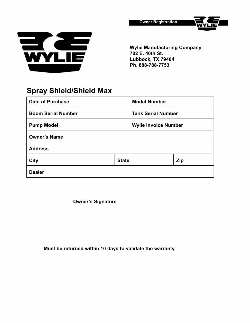
Wylie Manufacturing Company702 E. 40th St.Lubbock, TX 79404Ph. 888-788-7753
Date of Purchase Model Number
Boom Serial Number Tank Serial Number
Pump Model Wylie Invoice Number
Owner’s Name
Address
City State Zip
Dealer
Owner’s Signature
Must be returned within 10 days to validate the warranty.
Owner Registration
Spray Shield/Shield Max

1
Table of Contents
Table Of Contents
Safety Issues .............................................................................................................................................................2-3
Safety Decals & Placement .......................................................................................................................................... 4
Introduction ................................................................................................................................................................... 5
Inspection & Setup .................................................................................................................................................. 6-11 Initial Inspection ..................................................................................................................6 Changing From Transport To Field ..................................................................................6-8 Preparing Sprayer For Operation .................................................................................. 9-11 Folding Spray Shield Inspection and Setup ..................................................................... 11
Sprayer Operation .................................................................................................................................................12-16 General Operating Guidelines .....................................................................................12-13 Clearing Debris From System ..........................................................................................14 End Of Day Procedures ...................................................................................................15 Changing From Field To Transport ...................................................................................15 Preparing Trailer For Storage ...........................................................................................16
XR TeeJet™ Spray Tip Specifications Table .............................................................................................................. 17
Troubleshooting Guidelines ........................................................................................................................................ 18
Repair Parts........................................................................................................................................................ 19 – 30 Row Assembly ..........................................................................................................20 – 21 Transport Mount ...............................................................................................................22 Main Frame Assembly ......................................................................................................23 Tongue Assembly .............................................................................................................24 Wilger™ Tip Monitor .........................................................................................................25 Pump Assembly ........................................................................................................26 – 27 Controller Assembly .........................................................................................................28 Tip Monitor & Quick Fill Assembly ....................................................................................29 Folding Frame Assembly ..................................................................................................30
2
Safety PrecautionsBe alert when you see the above symbol in the manual. It warns of a hazard which might lead to injury. It means: Attention! Become alert! Your safety is Involved!
Three (3) words are associated with this symbol. They are:
DANGER – Indicates an imminently hazardous situation which, if not avoided, likely will cause serious injury or death. It is associated with the most extreme situations, typically for machine components, which, for functional purposes, can-not be guarded.
WARNING – Indicates a potentially hazardous situation, which, if not avoided, could result serious injury or death. Re-lates to hazards that are exposed when guards are removed and alerts against unsafe practices.
CAUTION – Indicates a potentially hazardous situation which, if not avoided, may result in minor or moderate injury. It may be used as an alert against unsafe practices.
Before UseDo not operate sprayer until this manual has been read and understood!
Thoroughly read and understand all instructions before operating this sprayer. If you have questions, please contact Wylie Manufacturing, 702 E. 40th St., Lubbock, TX, (888) 788-7753. You can also contact your nearest Wylie Spray Center. Place a “Slow Moving Vehicle” emblem on the rear of the unit prior to driving on open roads. Always wear safety goggles and rubber gloves when handling chemicals. Read and understand the chemical manufacturer’s safety guidelines on handling, mixing and application.
During Use Do not allow anyone to ride on sprayer during operation. Falling can cause injury. Ensure the tractor has sufficient weights to prevent tipping when spray tank is full. Reduce speed when crossing uneven or rough terrain. Always lower sprayer to level ground and turn off tractor engine before making adjustments or repairs.
Safety Issues
3
Safety Issues
After Use Inspect sprayer for wear or damage. Ensure that all fasteners and fittings are tight. Flush tank and pump with fresh water. Dispose of flush water using appropriate means. Carry out maintenance and/or lubrication procedures as outlined in this manual.
Always Keep hands, feet and clothing away from moving parts. Wear protective clothing and gloves when working with the hydraulic system. Escaping hydraulic fluid under pressure can penetrate skin causing serious injury: – Do Not use hands to check for leaks in hydraulic system, use cardboard or paper. – Stop tractor engine and relieve pressure before connecting or disconnecting lines. – Tighten all connections prior to starting engine or pressurizing line. – If any fluid is injected into the skin, obtain medical treatment immediately to avoid gangrene.
Operator’s Instructions Securely fasten seat belt if tractor is equipped with a Roll Over Protection System (ROPS). When possible, avoid operating the tractor near ditches, embankments and holes. Reduce speed when turning, crossing slopes and on rough, slick or muddy surfaces. Be aware of where you are going at all times; especially at row ends, roads and around trees. Do not permit others to ride. Operate tractor smoothly – no jerky turns, starts and stops. Hitch only to the drawbar and hitch points recommended by the tractor manufacturer. When tractor is idle, engage brakes and park lock securely. Tighten lug bolts before transporting and after the first five miles. Limit transport speed to 30 mph. Never transport sprayer, in end tow position, with liquid in tank.
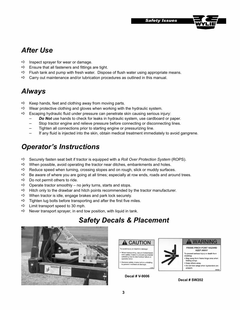
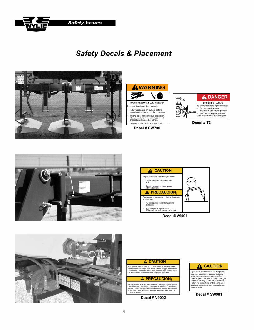
Safety Decals & Placement
Decal # SW202Decal # V-9006
4
Safety Decals & Placement
WARNING
HIGH-PRESSURE FLUID HAZARDTo prevent serious injury or death:
• Relieve pressure on system before repairing or adjusting or disconnecting.
• Wear proper hand and eye protection when searching for leaks. Use wood or cardboard instead of hands.• Keep all components in good repair.
CRUSHING HAZARDTo prevent serious injury or death:• Do not stand between implement and moving tractor• Stop tractor engine and set park brake before installing pins.
DANGER
CAUTION
PRECAUCION !
To prevent tipping or bending of frame:
• Do not transport sprayer with full tank.
• Do not transport or store sprayer with fluid in tank.
Para prevenir ladearse o doblar el chasis de la aspersora:
• NO transportar con el tanque lleno de liquido.
• NO transportar o guardar la aspersora con el liquido en el tanque.
This sprayer is recommended for use on biologically engineered,chemical resistant crops. Use of this sprayer to apply herbicide on conventional crops may cause damage to the crop! Follow chemi-cal manufacturer’s label directions for proper application.
CAUTION
PRECAUCION !
Esta aspersora esta’ recomendada para usarse en cultivos produ-cidos biotecnologicamente con resistencia quimica. El uso de esta aspersora en cultivos sin resistencia quimica, puede causar danos en el cultivo. Siga las instrucciones en la etiqueta de el producto que se va aplicar.
Agricultural chemicals can be dangerous.Improper selection of use can seriouslyinjure persons, animals, plants, soil or other property. BE SAFE. Select the right chemical for the job. Handle it with care. Follow the instructions on the container label and instructions from the equipment manufacturer.
CAUTION
Decal # SW700Decal # T3
Decal # V9001
Decal # V9002Decal # SW901
Safety Issues
5
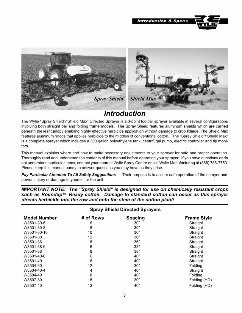
The Wylie “Spray Shield”/”Shield Max” Directed Sprayer is a 3-point toolbar sprayer available in several configurations involving both straight bar and folding frame models. The Spray Shield features aluminum shields which are carried beneath the leaf canopy enabling highly effective herbicide application without damage to crop foliage. The Shield Max features aluminum hoods that applies herbicide to the middles of conventional cotton. The “Spray Shield”/”Shield Max” is a complete sprayer which includes a 300 gallon polyethylene tank, centrifugal pump, electric controller and tip moni-tors.
This manual explains where and how to make necessary adjustments to your sprayer for safe and proper operation. Thoroughly read and understand the contents of this manual before operating your sprayer. If you have questions or do not understand particular items, contact your nearest Wylie Spray Center or call Wylie Manufacturing at (888) 788-7753. Please keep this manual handy to answer questions you may have as they arise.
Pay Particular Attention To All Safety Suggestions – Their purpose is to assure safe operation of the sprayer and prevent injury or damage to yourself or the unit.
Introduction & Specs
Introduction
IMPORTANT NOTE: The “Spray Shield” is designed for use on chemically resistant crops such as Roundup™ Ready cotton. Damage to standard cotton can occur as this sprayer directs herbicide into the row and onto the stem of the cotton plant!
Model Number # of Rows Spacing Frame StyleW3501-30-6 6 30” StraightW3501-30-8 8 30” StraightW3501-30-10 10 30” StraightW3501-30 12 30” StraightW3501-36 8 36” StraightW3501-38-6 6 38” StraightW3501-38 8 38” StraightW3501-40-6 6 40” StraightW3501-40 8 40” StraightW3504-30 12 30” FoldingW3504-40-4 4 40” StraightW3504-40 8 40” FoldingW3507-30 16 30” Folding (HD)W3507-40 12 40” Folding (HD)
Spray Shield Directed Sprayers
Spray Shield Shield Max
6
Inspection & Setup
Inspection & Setup
Figure S1 – Row Unit Spacing
Figure S2 – Removing Wheel Lock Pin
Your sprayer has been factory pre-assembled to insure optimum quality levels in final setup and assembly. Wylie embraces high quality control standards, however, adjustments may be required prior to initial use and before each season.
Initial Inspection(1) Check all bolts and fittings for tightness; especially lug bolts on the gauge/transport wheels (retighten these bolts after the first 5 miles of transport).
Spray tips were not installed at the factory. Flow lines must be flushed before installing strainers and tips.
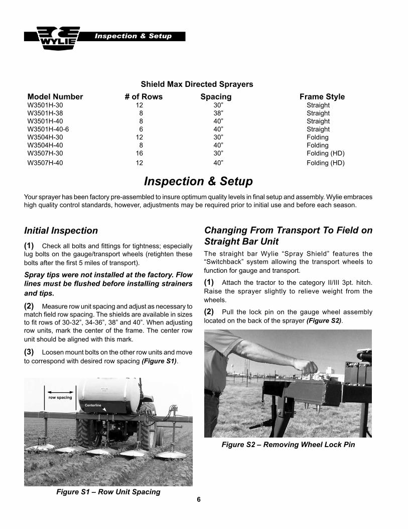
(2) Measure row unit spacing and adjust as necessary to match field row spacing. The shields are available in sizes to fit rows of 30-32”, 34-36”, 38” and 40”. When adjusting row units, mark the center of the frame. The center row unit should be aligned with this mark.
(3) Loosen mount bolts on the other row units and move to correspond with desired row spacing (Figure S1).
Changing From Transport To Field on Straight Bar UnitThe straight bar Wylie “Spray Shield” features the “Switchback” system allowing the transport wheels to function for gauge and transport.
(1) Attach the tractor to the category II/III 3pt. hitch. Raise the sprayer slightly to relieve weight from the wheels.
(2) Pull the lock pin on the gauge wheel assembly located on the back of the sprayer (Figure S2).
row spacing
Centerline
Model Number # of Rows Spacing Frame StyleW3501H-30 12 30” StraightW3501H-38 8 38” StraightW3501H-40 8 40” StraightW3501H-40-6 6 40” StraightW3504H-30 12 30” FoldingW3504H-40 8 40” FoldingW3507H-30 16 30” Folding (HD)W3507H-40 12 40” Folding (HD)
Shield Max Directed Sprayers
7
Inspection & Setup
Figure S3 – Locking Frame In Gauge Position
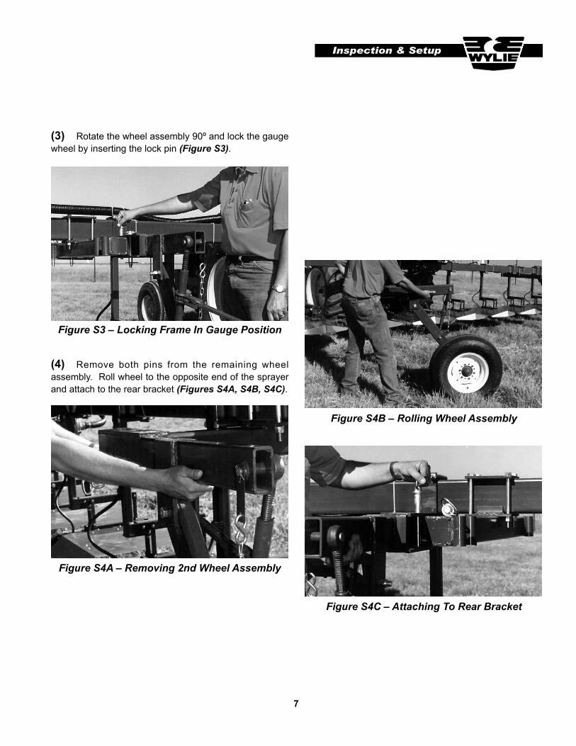
(3) Rotate the wheel assembly 90º and lock the gauge wheel by inserting the lock pin (Figure S3).
(4) Remove both pins from the remaining wheel assembly. Roll wheel to the opposite end of the sprayer and attach to the rear bracket (Figures S4A, S4B, S4C).
Figure S4A – Removing 2nd Wheel Assembly
Figure S4B – Rolling Wheel Assembly
Figure S4C – Attaching To Rear Bracket
8
Inspection & Setup
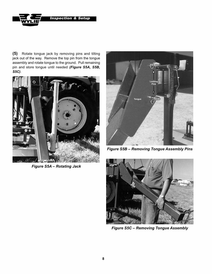
(5) Rotate tongue jack by removing pins and tilting jack out of the way. Remove the top pin from the tongue assembly and rotate tongue to the ground. Pull remaining pin and store tongue until needed (Figure S5A, S5B, S5C).
Figure S5A – Rotating Jack
Figure S5B – Removing Tongue Assembly Pins
Figure S5C – Removing Tongue Assembly
LockingPins
Tongue
9
Inspection & Setup
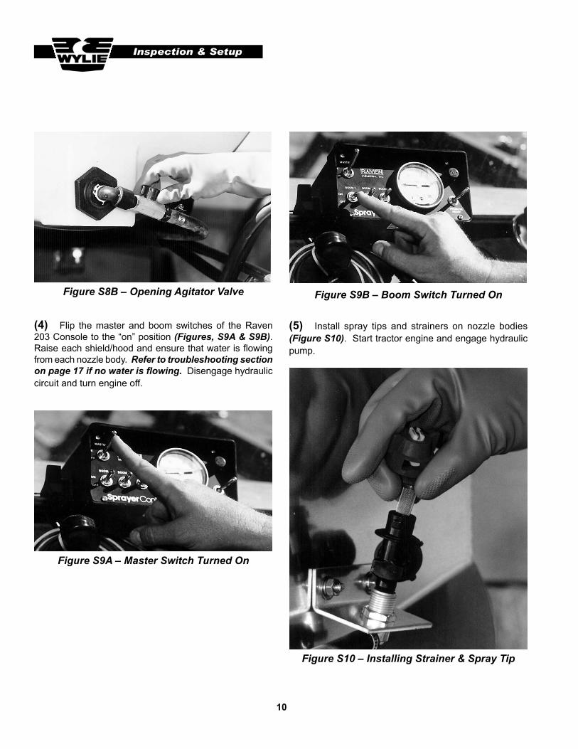
(3) Open the tank and agitator valve (Figures S8A & S8B). Start the tractor and engage hydraulic circuit supplying the pump.
Figure S7 – Hose Attached To “Quick-Fill” Coupler
Preparing Sprayer For Operation
(1) Connect hydraulic hoses from the pump to the tractor (follow directions shown in the pump manual).
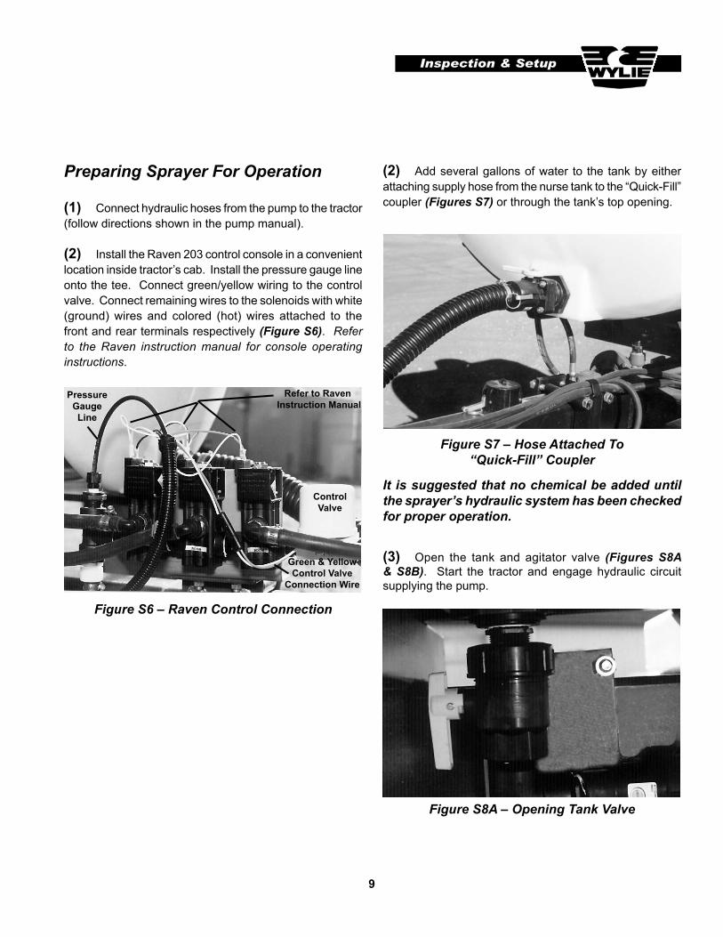
(2) Install the Raven 203 control console in a convenient location inside tractor’s cab. Install the pressure gauge line onto the tee. Connect green/yellow wiring to the control valve. Connect remaining wires to the solenoids with white (ground) wires and colored (hot) wires attached to the front and rear terminals respectively (Figure S6). Refer to the Raven instruction manual for console operating instructions.
It is suggested that no chemical be added until the sprayer’s hydraulic system has been checked for proper operation.
(2) Add several gallons of water to the tank by either attaching supply hose from the nurse tank to the “Quick-Fill” coupler (Figures S7) or through the tank’s top opening.
Figure S6 – Raven Control Connection
Figure S8A – Opening Tank Valve
Pressure Gauge Line
Refer to Raven Instruction Manual
ControlValve
Green & YellowControl Valve
Connection Wire
10
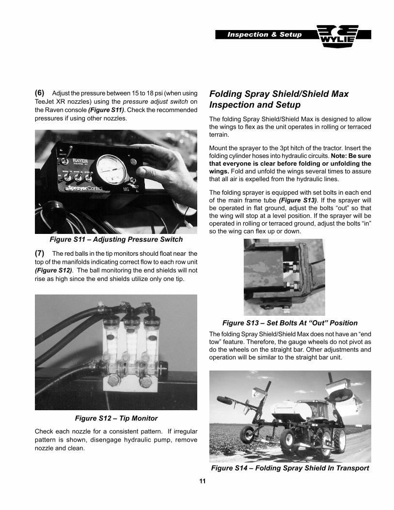
(4) Flip the master and boom switches of the Raven 203 Console to the “on” position (Figures, S9A & S9B). Raise each shield/hood and ensure that water is flowing from each nozzle body. Refer to troubleshooting section on page 17 if no water is flowing. Disengage hydraulic circuit and turn engine off.
Figure S9A – Master Switch Turned On
Figure S10 – Installing Strainer & Spray Tip
(5) Install spray tips and strainers on nozzle bodies (Figure S10). Start tractor engine and engage hydraulic pump.
Figure S9B – Boom Switch Turned On
Inspection & Setup
Figure S8B – Opening Agitator Valve
11
Figure S11 – Adjusting Pressure Switch
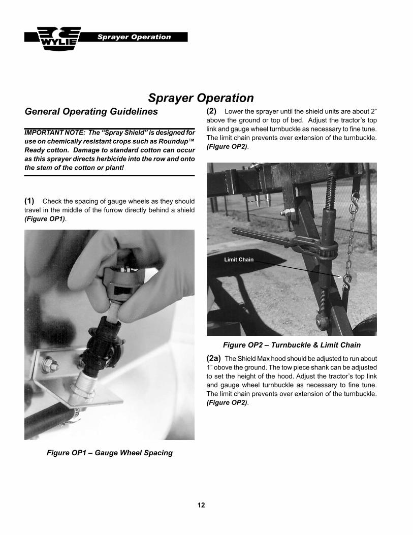
(6) Adjust the pressure between 15 to 18 psi (when using TeeJet XR nozzles) using the pressure adjust switch on the Raven console (Figure S11). Check the recommended pressures if using other nozzles.
(7) The red balls in the tip monitors should float near the top of the manifolds indicating correct flow to each row unit (Figure S12). The ball monitoring the end shields will not rise as high since the end shields utilize only one tip.
Figure S12 – Tip Monitor
Check each nozzle for a consistent pattern. If irregular pattern is shown, disengage hydraulic pump, remove nozzle and clean.
Inspection & Setup
Folding Spray Shield/Shield MaxInspection and SetupThe folding Spray Shield/Shield Max is designed to allow the wings to flex as the unit operates in rolling or terraced terrain.
Mount the sprayer to the 3pt hitch of the tractor. Insert the folding cylinder hoses into hydraulic circuits. Note: Be sure that everyone is clear before folding or unfolding the wings. Fold and unfold the wings several times to assure that all air is expelled from the hydraulic lines.
The folding sprayer is equipped with set bolts in each end of the main frame tube (Figure S13). If the sprayer will be operated in flat ground, adjust the bolts “out” so that the wing will stop at a level position. If the sprayer will be operated in rolling or terraced ground, adjust the bolts “in” so the wing can flex up or down.
Figure S13 – Set Bolts At “Out” PositionThe folding Spray Shield/Shield Max does not have an “end tow” feature. Therefore, the gauge wheels do not pivot as do the wheels on the straight bar. Other adjustments and operation will be similar to the straight bar unit.
Figure S14 – Folding Spray Shield In Transport
12
Sprayer Operation
Sprayer OperationGeneral Operating Guidelines
IMPORTANT NOTE: The “Spray Shield” is designed for use on chemically resistant crops such as Roundup™ Ready cotton. Damage to standard cotton can occur as this sprayer directs herbicide into the row and onto the stem of the cotton or plant!
Figure OP2 – Turnbuckle & Limit Chain
(2) Lower the sprayer until the shield units are about 2” above the ground or top of bed. Adjust the tractor’s top link and gauge wheel turnbuckle as necessary to fine tune. The limit chain prevents over extension of the turnbuckle. (Figure OP2).
(1) Check the spacing of gauge wheels as they should travel in the middle of the furrow directly behind a shield (Figure OP1).
Figure OP1 – Gauge Wheel Spacing
Limit Chain
(2a) The Shield Max hood should be adjusted to run about 1” obove the ground. The tow piece shank can be adjusted to set the height of the hood. Adjust the tractor’s top link and gauge wheel turnbuckle as necessary to fine tune. The limit chain prevents over extension of the turnbuckle. (Figure OP2).
13
The “Spray Shield” should be adjusted so that shield units ride between the ground and leaf canopy. Operating speed should correspond with the capacity of the “XR” spray tips at 15–18 psi. Refer to the spray tip table on page 16. Other tips such as the Air Induction (AI) tips can also be used on the Spray Shield. Pressures of 30 psi and higher can be used with the AI tip. Refer to the TeeJet spray tip catalog for more information.
Do not operate the “Spray Shield” or “Shield Max” greater than 20 psi when using the “XR” tip. Pressure over 20 psi can cause “fogging” of the spray behind the shield under certain conditions.
Figure OP3 – Leveling Screw
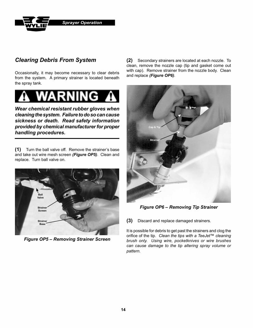
Figure OP4 – Clearing Shield Obstructions
(4) Each row unit is equipped with a rotating mount arm allowing the shields to rotate upward when obstructions are hit. It may be necessary to raise the sprayer slightly in order to clear the obstruction allowing the row unit to reset (Figure OP4).
Sprayer Operation
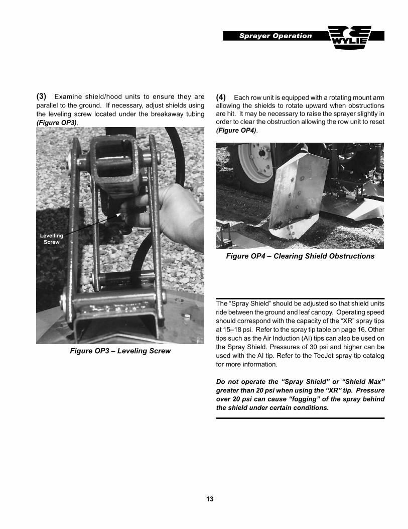
(3) Examine shield/hood units to ensure they are parallel to the ground. If necessary, adjust shields using the leveling screw located under the breakaway tubing (Figure OP3).
LevellingScrew
14
Sprayer Operation
Occasionally, it may become necessary to clear debris from the system. A primary strainer is located beneath the spray tank.
Clearing Debris From System
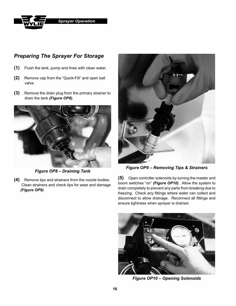
Figure OP6 – Removing Tip Strainer
(2) Secondary strainers are located at each nozzle. To clean, remove the nozzle cap (tip and gasket come out with cap). Remove strainer from the nozzle body. Clean and replace (Figure OP6).
Wear chemical resistant rubber gloves when cleaning the system. Failure to do so can cause sickness or death. Read safety information provided by chemical manufacturer for proper handling procedures.
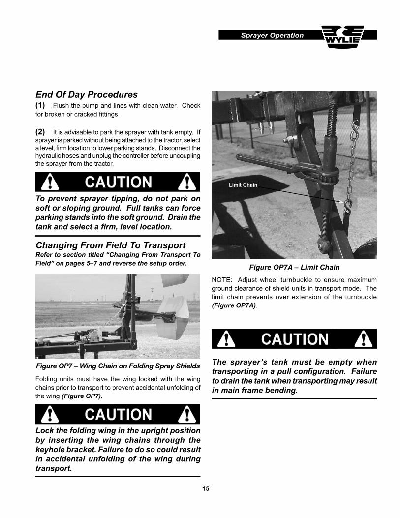
(1) Turn the ball valve off. Remove the strainer’s base and take out wire mesh screen (Figure OP5). Clean and replace. Turn ball valve on.
(3) Discard and replace damaged strainers.
It is possible for debris to get past the strainers and clog the orifice of the tip. Clean the tips with a TeeJet™ cleaning brush only. Using wire, pocketknives or wire brushes can cause damage to the tip altering spray volume or pattern.
Figure OP5 – Removing Strainer Screen
BallValve
StrainerScreen
StrainerBase
Cap & Tip
Strainer
15
Sprayer Operation
Changing From Field To TransportRefer to section titled “Changing From Transport To Field” on pages 5–7 and reverse the setup order.
The sprayer’s tank must be empty when transporting in a pull configuration. Failure to drain the tank when transporting may result in main frame bending.
(1) Flush the pump and lines with clean water. Check for broken or cracked fittings.
(2) It is advisable to park the sprayer with tank empty. If sprayer is parked without being attached to the tractor, select a level, firm location to lower parking stands. Disconnect the hydraulic hoses and unplug the controller before uncoupling the sprayer from the tractor.
End Of Day Procedures
To prevent sprayer tipping, do not park on soft or sloping ground. Full tanks can force parking stands into the soft ground. Drain the tank and select a firm, level location.
Figure OP7A – Limit Chain
NOTE: Adjust wheel turnbuckle to ensure maximum ground clearance of shield units in transport mode. The limit chain prevents over extension of the turnbuckle (Figure OP7A).
Limit Chain
Folding units must have the wing locked with the wing chains prior to transport to prevent accidental unfolding of the wing (Figure OP7).
Figure OP7 – Wing Chain on Folding Spray Shields
Lock the folding wing in the upright position by inserting the wing chains through the keyhole bracket. Failure to do so could result in accidental unfolding of the wing during transport.
16
Sprayer Operation
(4) Remove tips and strainers from the nozzle bodies. Clean strainers and check tips for wear and damage (Figure OP9).
Figure OP9 – Removing Tips & Strainers
(5) Open controller solenoids by turning the master and boom switches “on” (Figure OP10). Allow the system to drain completely to prevent any parts from breaking due to freezing. Check any fittings where water can collect and disconnect to allow drainage. Reconnect all fittings and ensure tightness when sprayer is drained.
Figure OP10 – Opening Solenoids
Preparing The Sprayer For Storage
(1) Flush the tank, pump and lines with clean water.
(2) Remove cap from the “Quick-Fill” and open ball valve.
(3) Remove the drain plug from the primary strainer to drain the tank (Figure OP8).
Figure OP8 – Draining Tank
17
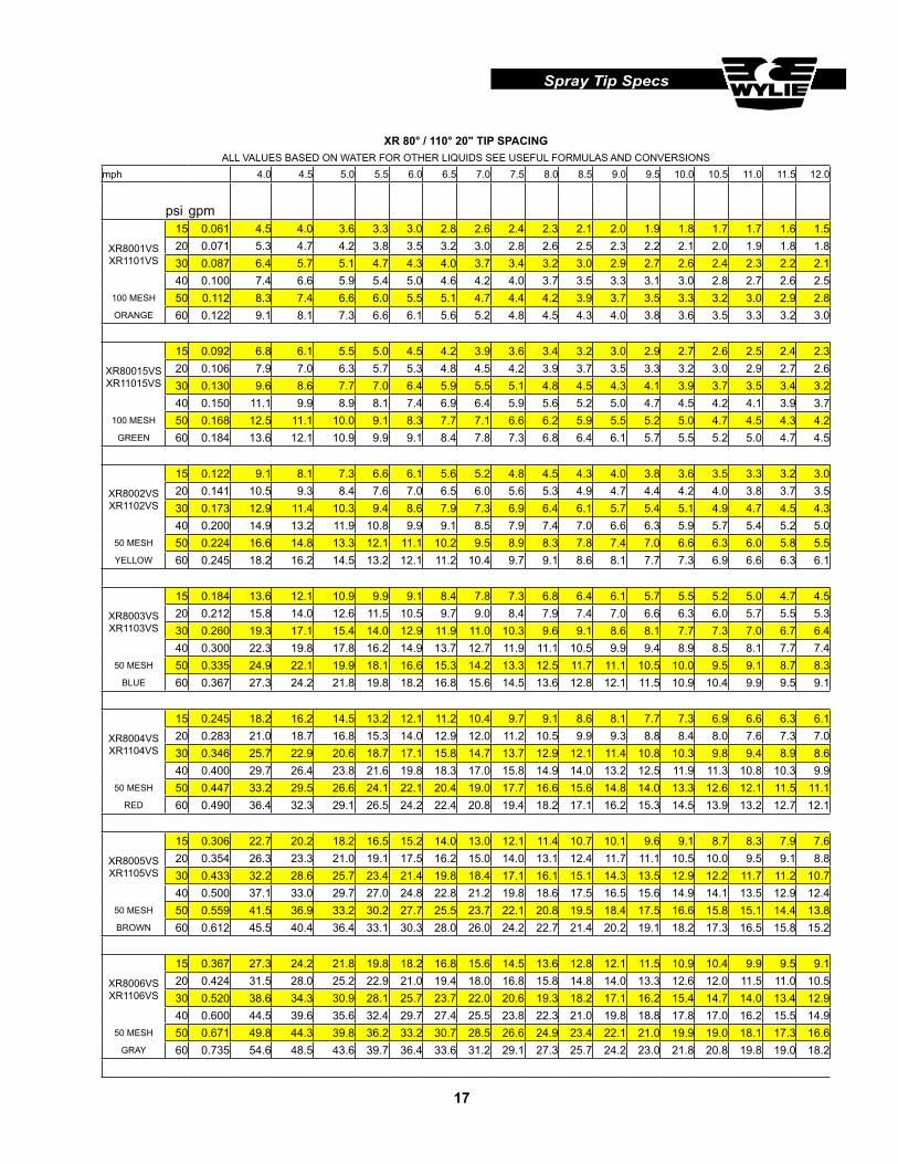
Spray Tip Specs
XR 80° / 110° 20" TIP SPACINGALL VALUES BASED ON WATER FOR OTHER LIQUIDS SEE USEFUL FORMULAS AND CONVERSIONS
mph 4.0 4.5 5.0 5.5 6.0 6.5 7.0 7.5 8.0 8.5 9.0 9.5 10.0 10.5 11.0 11.5 12.0
psi gpm
XR8001VS XR1101VS
15 0.061 4.5 4.0 3.6 3.3 3.0 2.8 2.6 2.4 2.3 2.1 2.0 1.9 1.8 1.7 1.7 1.6 1.520 0.071 5.3 4.7 4.2 3.8 3.5 3.2 3.0 2.8 2.6 2.5 2.3 2.2 2.1 2.0 1.9 1.8 1.830 0.087 6.4 5.7 5.1 4.7 4.3 4.0 3.7 3.4 3.2 3.0 2.9 2.7 2.6 2.4 2.3 2.2 2.140 0.100 7.4 6.6 5.9 5.4 5.0 4.6 4.2 4.0 3.7 3.5 3.3 3.1 3.0 2.8 2.7 2.6 2.5
100 MESH 50 0.112 8.3 7.4 6.6 6.0 5.5 5.1 4.7 4.4 4.2 3.9 3.7 3.5 3.3 3.2 3.0 2.9 2.8ORANGE 60 0.122 9.1 8.1 7.3 6.6 6.1 5.6 5.2 4.8 4.5 4.3 4.0 3.8 3.6 3.5 3.3 3.2 3.0
XR80015VS XR11015VS
15 0.092 6.8 6.1 5.5 5.0 4.5 4.2 3.9 3.6 3.4 3.2 3.0 2.9 2.7 2.6 2.5 2.4 2.320 0.106 7.9 7.0 6.3 5.7 5.3 4.8 4.5 4.2 3.9 3.7 3.5 3.3 3.2 3.0 2.9 2.7 2.630 0.130 9.6 8.6 7.7 7.0 6.4 5.9 5.5 5.1 4.8 4.5 4.3 4.1 3.9 3.7 3.5 3.4 3.240 0.150 11.1 9.9 8.9 8.1 7.4 6.9 6.4 5.9 5.6 5.2 5.0 4.7 4.5 4.2 4.1 3.9 3.7
100 MESH 50 0.168 12.5 11.1 10.0 9.1 8.3 7.7 7.1 6.6 6.2 5.9 5.5 5.2 5.0 4.7 4.5 4.3 4.2GREEN 60 0.184 13.6 12.1 10.9 9.9 9.1 8.4 7.8 7.3 6.8 6.4 6.1 5.7 5.5 5.2 5.0 4.7 4.5
XR8002VS XR1102VS
15 0.122 9.1 8.1 7.3 6.6 6.1 5.6 5.2 4.8 4.5 4.3 4.0 3.8 3.6 3.5 3.3 3.2 3.020 0.141 10.5 9.3 8.4 7.6 7.0 6.5 6.0 5.6 5.3 4.9 4.7 4.4 4.2 4.0 3.8 3.7 3.530 0.173 12.9 11.4 10.3 9.4 8.6 7.9 7.3 6.9 6.4 6.1 5.7 5.4 5.1 4.9 4.7 4.5 4.340 0.200 14.9 13.2 11.9 10.8 9.9 9.1 8.5 7.9 7.4 7.0 6.6 6.3 5.9 5.7 5.4 5.2 5.0
50 MESH 50 0.224 16.6 14.8 13.3 12.1 11.1 10.2 9.5 8.9 8.3 7.8 7.4 7.0 6.6 6.3 6.0 5.8 5.5YELLOW 60 0.245 18.2 16.2 14.5 13.2 12.1 11.2 10.4 9.7 9.1 8.6 8.1 7.7 7.3 6.9 6.6 6.3 6.1
XR8003VS XR1103VS
15 0.184 13.6 12.1 10.9 9.9 9.1 8.4 7.8 7.3 6.8 6.4 6.1 5.7 5.5 5.2 5.0 4.7 4.520 0.212 15.8 14.0 12.6 11.5 10.5 9.7 9.0 8.4 7.9 7.4 7.0 6.6 6.3 6.0 5.7 5.5 5.330 0.260 19.3 17.1 15.4 14.0 12.9 11.9 11.0 10.3 9.6 9.1 8.6 8.1 7.7 7.3 7.0 6.7 6.440 0.300 22.3 19.8 17.8 16.2 14.9 13.7 12.7 11.9 11.1 10.5 9.9 9.4 8.9 8.5 8.1 7.7 7.4
50 MESH 50 0.335 24.9 22.1 19.9 18.1 16.6 15.3 14.2 13.3 12.5 11.7 11.1 10.5 10.0 9.5 9.1 8.7 8.3BLUE 60 0.367 27.3 24.2 21.8 19.8 18.2 16.8 15.6 14.5 13.6 12.8 12.1 11.5 10.9 10.4 9.9 9.5 9.1
XR8004VS XR1104VS
15 0.245 18.2 16.2 14.5 13.2 12.1 11.2 10.4 9.7 9.1 8.6 8.1 7.7 7.3 6.9 6.6 6.3 6.120 0.283 21.0 18.7 16.8 15.3 14.0 12.9 12.0 11.2 10.5 9.9 9.3 8.8 8.4 8.0 7.6 7.3 7.030 0.346 25.7 22.9 20.6 18.7 17.1 15.8 14.7 13.7 12.9 12.1 11.4 10.8 10.3 9.8 9.4 8.9 8.640 0.400 29.7 26.4 23.8 21.6 19.8 18.3 17.0 15.8 14.9 14.0 13.2 12.5 11.9 11.3 10.8 10.3 9.9
50 MESH 50 0.447 33.2 29.5 26.6 24.1 22.1 20.4 19.0 17.7 16.6 15.6 14.8 14.0 13.3 12.6 12.1 11.5 11.1RED 60 0.490 36.4 32.3 29.1 26.5 24.2 22.4 20.8 19.4 18.2 17.1 16.2 15.3 14.5 13.9 13.2 12.7 12.1
XR8005VS XR1105VS
15 0.306 22.7 20.2 18.2 16.5 15.2 14.0 13.0 12.1 11.4 10.7 10.1 9.6 9.1 8.7 8.3 7.9 7.620 0.354 26.3 23.3 21.0 19.1 17.5 16.2 15.0 14.0 13.1 12.4 11.7 11.1 10.5 10.0 9.5 9.1 8.830 0.433 32.2 28.6 25.7 23.4 21.4 19.8 18.4 17.1 16.1 15.1 14.3 13.5 12.9 12.2 11.7 11.2 10.740 0.500 37.1 33.0 29.7 27.0 24.8 22.8 21.2 19.8 18.6 17.5 16.5 15.6 14.9 14.1 13.5 12.9 12.4
50 MESH 50 0.559 41.5 36.9 33.2 30.2 27.7 25.5 23.7 22.1 20.8 19.5 18.4 17.5 16.6 15.8 15.1 14.4 13.8BROWN 60 0.612 45.5 40.4 36.4 33.1 30.3 28.0 26.0 24.2 22.7 21.4 20.2 19.1 18.2 17.3 16.5 15.8 15.2
XR8006VS XR1106VS
15 0.367 27.3 24.2 21.8 19.8 18.2 16.8 15.6 14.5 13.6 12.8 12.1 11.5 10.9 10.4 9.9 9.5 9.120 0.424 31.5 28.0 25.2 22.9 21.0 19.4 18.0 16.8 15.8 14.8 14.0 13.3 12.6 12.0 11.5 11.0 10.530 0.520 38.6 34.3 30.9 28.1 25.7 23.7 22.0 20.6 19.3 18.2 17.1 16.2 15.4 14.7 14.0 13.4 12.940 0.600 44.5 39.6 35.6 32.4 29.7 27.4 25.5 23.8 22.3 21.0 19.8 18.8 17.8 17.0 16.2 15.5 14.9
50 MESH 50 0.671 49.8 44.3 39.8 36.2 33.2 30.7 28.5 26.6 24.9 23.4 22.1 21.0 19.9 19.0 18.1 17.3 16.6GRAY 60 0.735 54.6 48.5 43.6 39.7 36.4 33.6 31.2 29.1 27.3 25.7 24.2 23.0 21.8 20.8 19.8 19.0 18.2
18
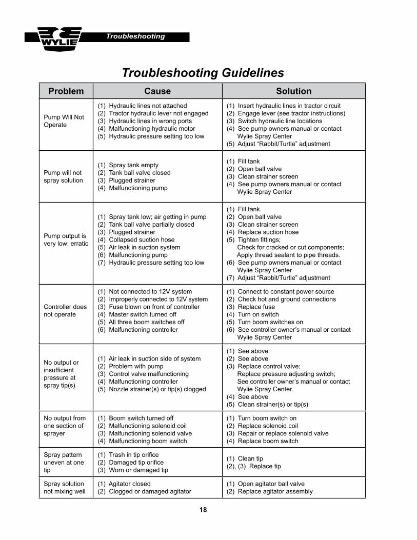
Troubleshooting Guidelines
Troubleshooting
Problem Cause Solution
Pump Will Not Operate
(1) Hydraulic lines not attached(2) Tractor hydraulic lever not engaged(3) Hydraulic lines in wrong ports(4) Malfunctioning hydraulic motor(5) Hydraulic pressure setting too low
(1) Insert hydraulic lines in tractor circuit(2) Engage lever (see tractor instructions)(3) Switch hydraulic line locations(4) See pump owners manual or contact Wylie Spray Center(5) Adjust “Rabbit/Turtle” adjustment
Pump will not spray solution
(1) Spray tank empty(2) Tank ball valve closed(3) Plugged strainer(4) Malfunctioning pump
(1) Fill tank(2) Open ball valve(3) Clean strainer screen(4) See pump owners manual or contact Wylie Spray Center
Pump output is very low; erratic
(1) Spray tank low; air getting in pump(2) Tank ball valve partially closed(3) Plugged strainer(4) Collapsed suction hose(5) Air leak in suction system(6) Malfunctioning pump(7) Hydraulic pressure setting too low
(1) Fill tank(2) Open ball valve(3) Clean strainer screen(4) Replace suction hose(5) Tighten fittings; Check for cracked or cut components; Apply thread sealant to pipe threads.(6) See pump owners manual or contact Wylie Spray Center(7) Adjust “Rabbit/Turtle” adjustment
Controller does not operate
(1) Not connected to 12V system(2) Improperly connected to 12V system(3) Fuse blown on front of controller(4) Master switch turned off(5) All three boom switches off(6) Malfunctioning controller
(1) Connect to constant power source(2) Check hot and ground connections(3) Replace fuse(4) Turn on switch(5) Turn boom switches on(6) See controller owner’s manual or contact Wylie Spray Center
No output or insufficient pressure at spray tip(s)
(1) Air leak in suction side of system(2) Problem with pump(3) Control valve malfunctioning(4) Malfunctioning controller(5) Nozzle strainer(s) or tip(s) clogged
(1) See above(2) See above(3) Replace control valve; Replace pressure adjusting switch; See controller owner’s manual or contact Wylie Spray Center.(4) See above(5) Clean strainer(s) or tip(s)
No output from one section of sprayer
(1) Boom switch turned off(2) Malfunctioning solenoid coil(3) Malfunctioning solenoid valve(4) Malfunctioning boom switch
(1) Turn boom switch on(2) Replace solenoid coil(3) Repair or replace solenoid valve(4) Replace boom switch
Spray pattern uneven at one tip
(1) Trash in tip orifice(2) Damaged tip orifice(3) Worn or damaged tip
(1) Clean tip(2), (3) Replace tip
Spray solution not mixing well
(1) Agitator closed(2) Clogged or damaged agitator
(1) Open agitator ball valve(2) Replace agitator assembly