Embed Size (px)
DESCRIPTION
Spring 2006 EE 5304/EETS 7304 Internet Protocols. Lecture 5. Routing protocols. Tom Oh Dept of Electrical Engineering [email protected]. Administrative Issues. Here are some useful books for learning OPNET. - PowerPoint PPT Presentation
Citation preview
TO 2-14-06 p. 1
Spring 2006
EE 5304/EETS 7304 Internet Protocols
Tom OhDept of Electrical Engineering
Lecture 5
Routing protocols
TO 2-14-06 p. 2
Administrative Issues
Here are some useful books for learning OPNET.
Computer Networks – A Systems Approach--Third Edition by Larry L. Peterson & Bruce S. Davie • Network Simulation Experiments Manual (The Morgan
Kaufmann Series in Networking) by Emad Aboelela Modeling and Simulating Communications Networks: A
Hands-on Approach Using OPNET (Textbook Binding) by Irene Katzela
TO 2-14-06 p. 3
Administrative Issues (cont)
Data and Computer Communications, Seventh Edition
Computer Networking with Internet Protocols, Fourth Edition
by William Stalling• Data and Computer Communications and Computer
Networking with internet Protocols and Technology: Opnet Lab Manual to Accompany the seventh edition and fourth edition (Paperback)
I have posted the second homework solution today.
TO 2-14-06 p. 4
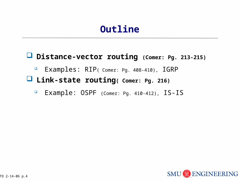
Outline
Distance-vector routing (Comer: Pg. 213-215)
Examples: RIP( Comer: Pg. 408-410), IGRP
Link-state routing( Comer: Pg. 216)
Example: OSPF (Comer: Pg. 410-412), IS-IS
TO 2-14-06 p. 5
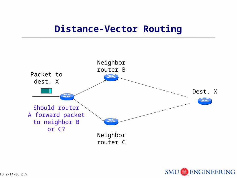
Distance-Vector Routing
Should routerA forward packet
to neighbor Bor C?
Packet todest. X
Dest. X
Neighborrouter B
Neighborrouter C
TO 2-14-06 p. 6
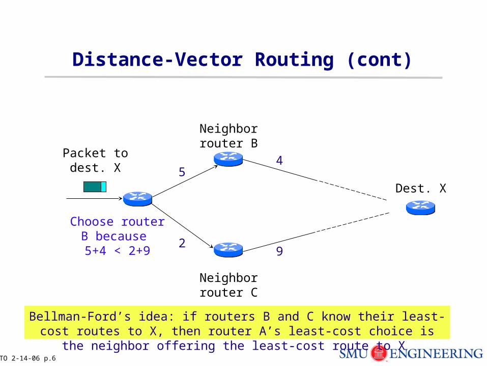
Distance-Vector Routing (cont)
Packet todest. X
Dest. X
Neighborrouter B
Neighborrouter C
Bellman-Ford’s idea: if routers B and C know their least-cost routes to X, then router A’s least-cost choice is the neighbor offering the least-cost route to X
54
29
Choose router B because 5+4 < 2+9
TO 2-14-06 p. 7
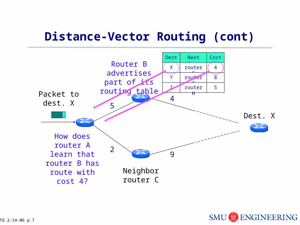
Distance-Vector Routing (cont)
Packet todest. X
Dest. X
Neighborrouter C
Dest.
5
29
How does router A learn that router B
has route with cost 4?
Next hop Cost
X router F 4
Y router G 8
Z router H 5
Router B advertises part of its routing table
4
TO 2-14-06 p. 8
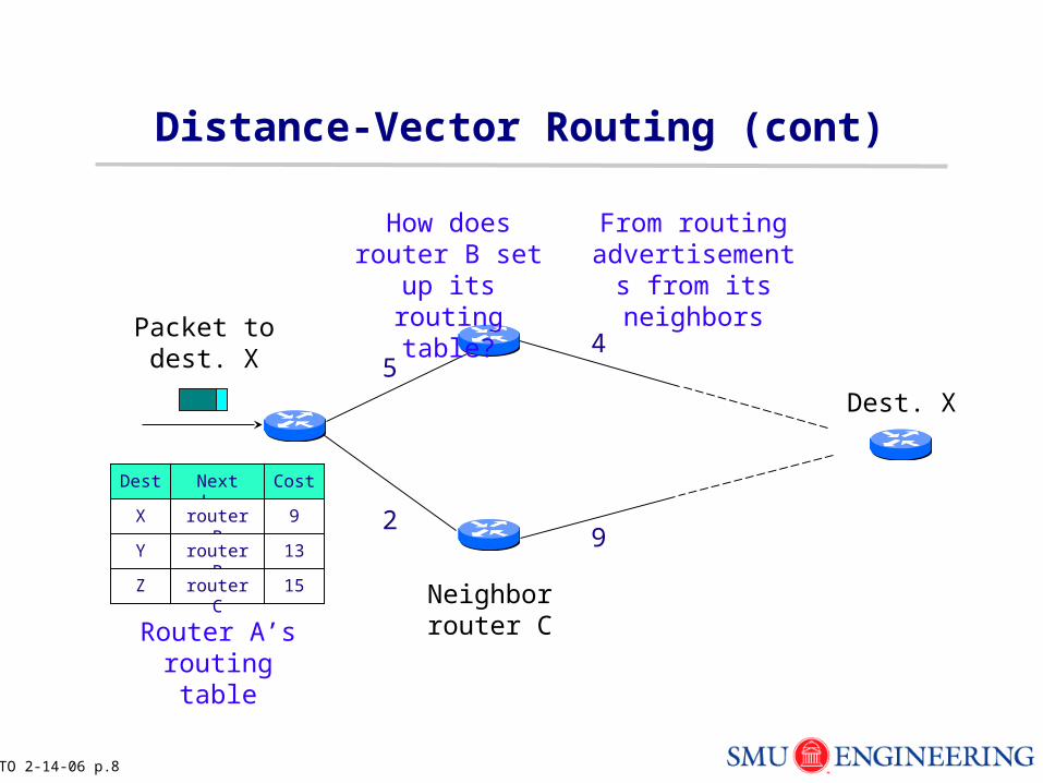
Distance-Vector Routing (cont)
Packet todest. X
Dest. X
Neighborrouter C
Dest.
5
29
Next hop Cost
X router B 9
Y router B 13
Z router C 15
How does router B set up its routing
table?
4
From routing advertisements
from its neighbors
Router A’s routing table
TO 2-14-06 p. 9
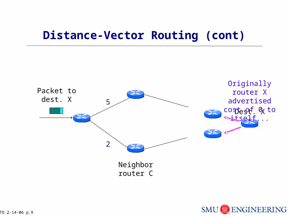
Distance-Vector Routing (cont)
Packet todest. X
Dest. X
Neighborrouter C
5
2
Originally router X advertised cost of
0 to itself...
TO 2-14-06 p. 10
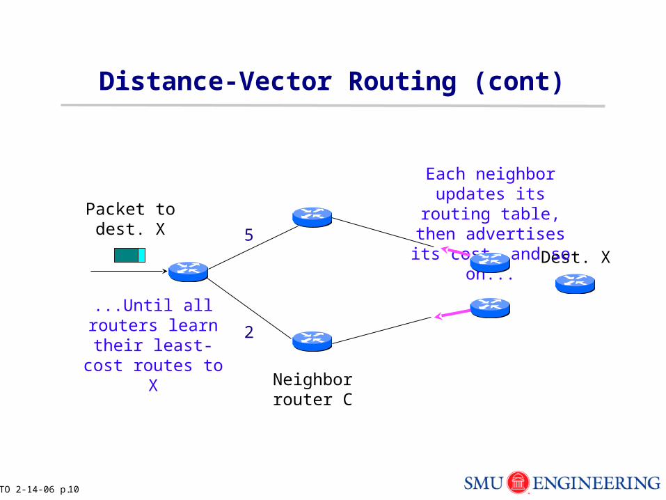
Distance-Vector Routing (cont)
Packet todest. X
Dest. X
Neighborrouter C
5
2
Each neighbor updates its routing table, then
advertises its cost, and so on...
...Until all routers learn their least-cost routes to X
TO 2-14-06 p. 11
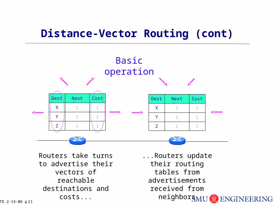
Distance-Vector Routing (cont)
Routers take turns to advertise their vectors of reachable destinations
and costs...
Basic operation
Dest. Next hop Cost
X : :
Y : :
Z : :
Dest. Next hop Cost
X : :
Y : :
Z : :
...Routers update their routing tables from
advertisements received from neighbors
TO 2-14-06 p. 12
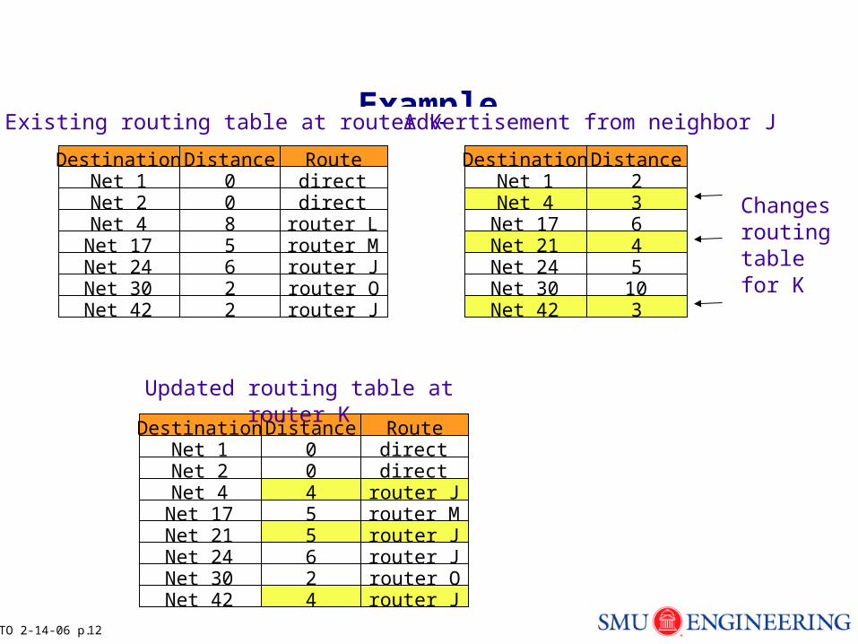
Example
Destination Distance RouteNet 1 0 directNet 2 0 directNet 4 8 router L
Net 17 5 router MNet 24 6 router JNet 30 2 router QNet 42 2 router J
Destination DistanceNet 1 2Net 4 3
Net 17 6Net 21 4Net 24 5Net 30 10Net 42 3
Destination Distance Route0 direct0 direct455624
Existing routing table at router K Advertisement from neighbor J
Updated routing table at router K
Changesroutingtablefor K
Net 1Net 2Net 4
Net 17
Net 24Net 30Net 42
Net 21
router Jrouter Mrouter J
router Qrouter J
router J
TO 2-14-06 p. 13
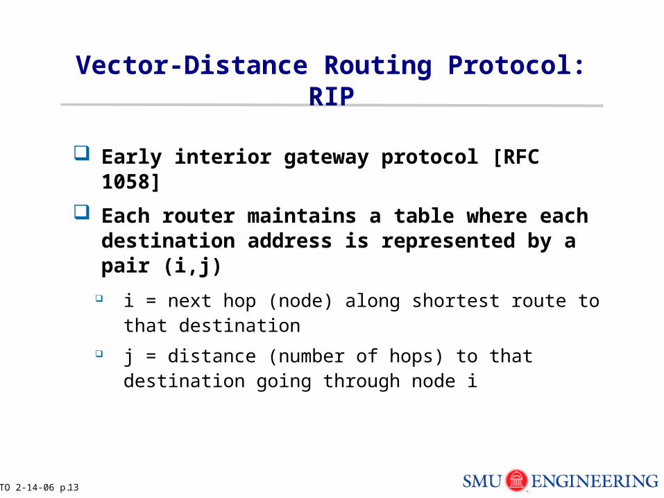
Vector-Distance Routing Protocol: RIP
Early interior gateway protocol [RFC 1058]
Each router maintains a table where each destination address is represented by a pair (i,j)
i = next hop (node) along shortest route to that destination j = distance (number of hops) to that destination going
through node i
TO 2-14-06 p. 14
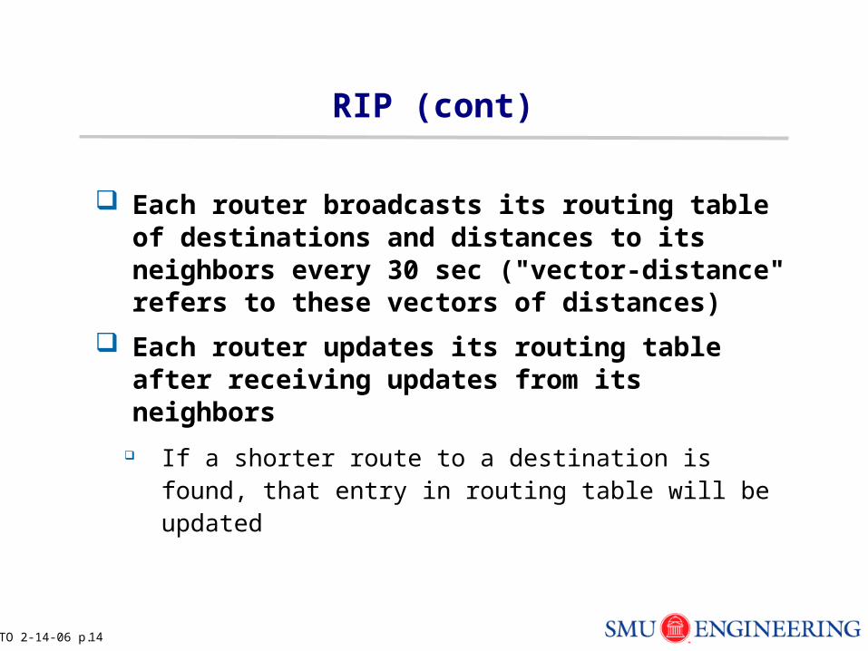
RIP (cont)
Each router broadcasts its routing table of destinations and distances to its neighbors every 30 sec ("vector-distance" refers to these vectors of distances)
Each router updates its routing table after receiving updates from its neighbors
If a shorter route to a destination is found, that entry in routing table will be updated
TO 2-14-06 p. 15
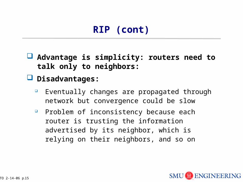
RIP (cont)
Advantage is simplicity: routers need to talk only to neighbors:
Disadvantages:
Eventually changes are propagated through network but convergence could be slow
Problem of inconsistency because each router is trusting the information advertised by its neighbor, which is relying on their neighbors, and so on
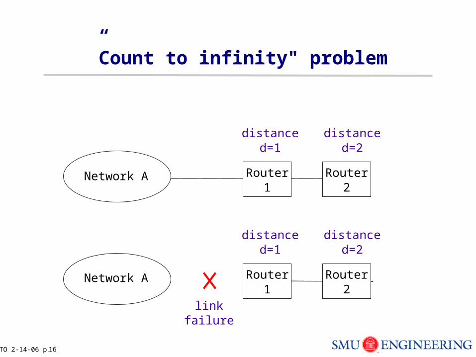
TO 2-14-06 p. 16
”Count to infinity" problem
Network A Router1
Router2
distanced=1
distanced=2
Network A Router1
Router2
distanced=1
distanced=2
linkfailure
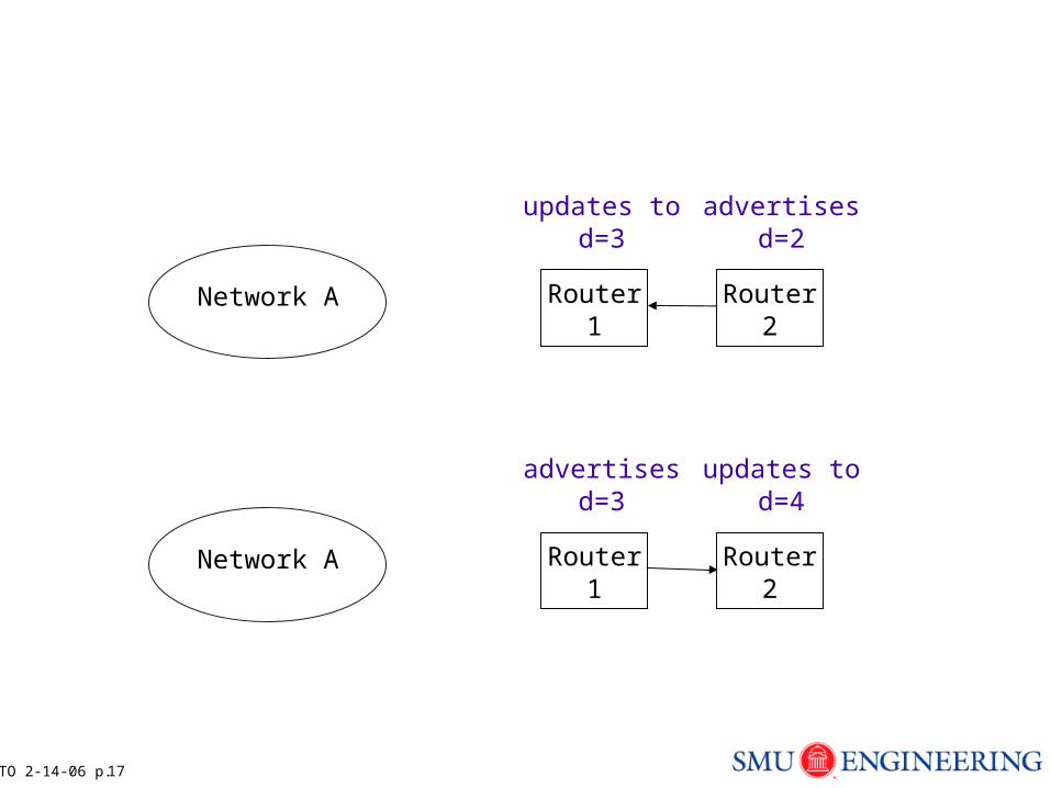
TO 2-14-06 p. 17
Router1
Network A Router1
Router2
advertisesd=3
updates tod=4
Network A Router2
updates tod=3
advertisesd=2
TO 2-14-06 p. 18
RIP (cont)
Also not scalable to larger networks:
More routers → longer to propagate changes through network
Each update message (vectors) becomes longer because more destinations in larger networks
TO 2-14-06 p. 19
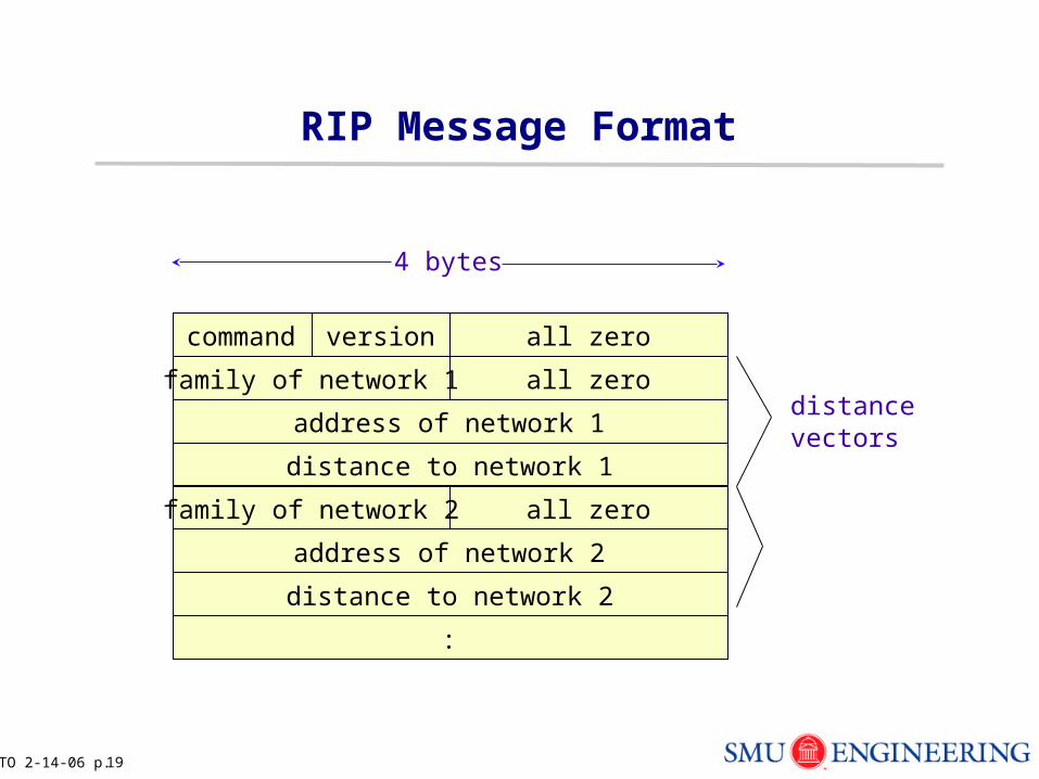
RIP Message Format
all zerofamily of network 1
command version all zero
address of network 1
distance to network 1
all zerofamily of network 2
address of network 2
distance to network 2
:
distancevectors
4 bytes
TO 2-14-06 p. 20
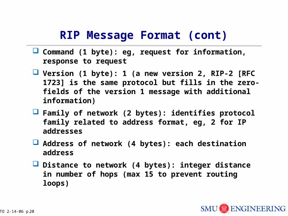
RIP Message Format (cont) Command (1 byte): eg, request for information,
response to request
Version (1 byte): 1 (a new version 2, RIP-2 [RFC 1723] is the same protocol but fills in the zero-fields of the version 1 message with additional information)
Family of network (2 bytes): identifies protocol family related to address format, eg, 2 for IP addresses
Address of network (4 bytes): each destination address
Distance to network (4 bytes): integer distance in number of hops (max 15 to prevent routing loops)
TO 2-14-06 p. 21
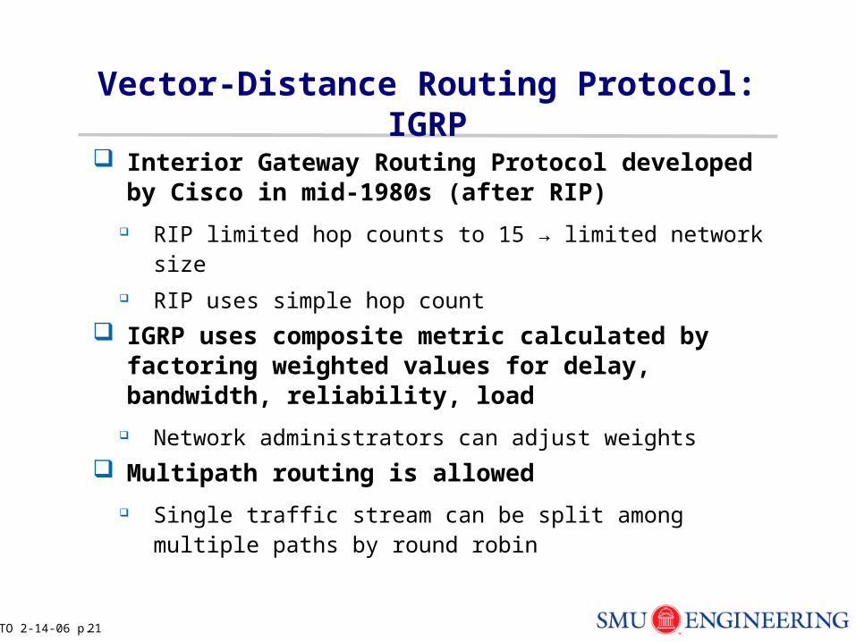
Vector-Distance Routing Protocol: IGRP
Interior Gateway Routing Protocol developed by Cisco in mid-1980s (after RIP)
RIP limited hop counts to 15 → limited network size RIP uses simple hop count
IGRP uses composite metric calculated by factoring weighted values for delay, bandwidth, reliability, load
Network administrators can adjust weights
Multipath routing is allowed
Single traffic stream can be split among multiple paths by round robin
TO 2-14-06 p. 22
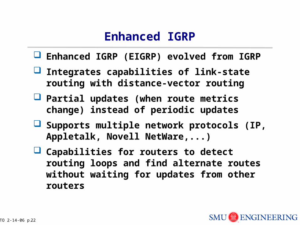
Enhanced IGRP
Enhanced IGRP (EIGRP) evolved from IGRP
Integrates capabilities of link-state routing with distance-vector routing
Partial updates (when route metrics change) instead of periodic updates
Supports multiple network protocols (IP, Appletalk, Novell NetWare,...)
Capabilities for routers to detect routing loops and find alternate routes without waiting for updates from other routers
TO 2-14-06 p. 23
Link-State Routing
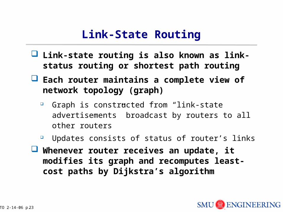
Link-state routing is also known as link-status routing or shortest path routing
Each router maintains a complete view of network topology (graph)
Graph is constructed from “link-state advertisements” broadcast by routers to all other routers
Updates consists of status of router’s links
Whenever router receives an update, it modifies its graph and recomputes least-cost paths by Dijkstra’s algorithm
TO 2-14-06 p. 24
OSPF (cont)
Advantages:
Routing decisions should be consistent among all routers Each router performs its own computations on same
network map, therefore is not dependent on trustworthiness of neighbor’s data
Changes are propagated faster than distance-vector routing
Disadvantage: flooding of link-state advertisements increases with size of network, but ways to limit
TO 2-14-06 p. 25
OSPF (cont)
Disadvantage: flooding of link-state advertisements increases with size of network, but ways to limit
Messages are constant length - depends on number of links per router, but does not depend on network size
Routing updates are sent only for significant changes OSPF allows hierarchical routing - network is divided into
areas, which reduces routing traffic
TO 2-14-06 p. 26
Link-State Routing Protocol: OSPF
Open Shortest Path First proposed by IETF in late 1980s to overcome disadvantages of RIP [RFC 1583]
Based largely on research done at BBN Open means public standard SPF refers to Dijkstra’s algorithm
TO 2-14-06 p. 27
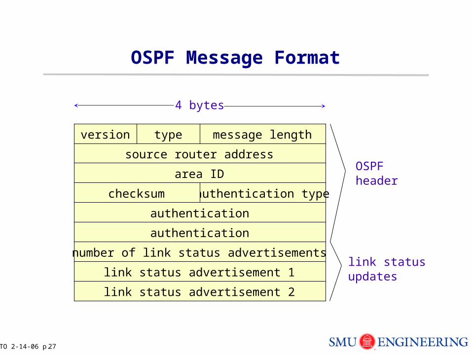
OSPF Message Format
source router address
version type message length
area ID
authentication typechecksum
authentication
authentication
OSPFheader
number of link status advertisements
link status advertisement 1
link status advertisement 2
link statusupdates
4 bytes
TO 2-14-06 p. 28
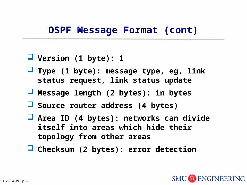
OSPF Message Format (cont)
Version (1 byte): 1
Type (1 byte): message type, eg, link status request, link status update
Message length (2 bytes): in bytes
Source router address (4 bytes)
Area ID (4 bytes): networks can divide itself into areas which hide their topology from other areas
Checksum (2 bytes): error detection
TO 2-14-06 p. 29
OSPF (cont)
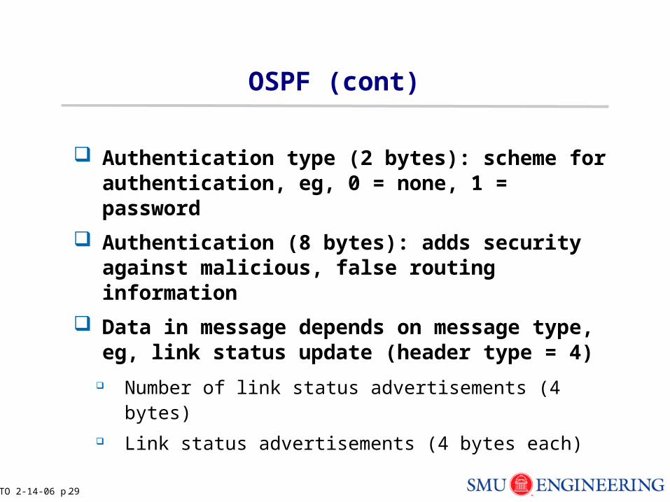
Authentication type (2 bytes): scheme for authentication, eg, 0 = none, 1 = password
Authentication (8 bytes): adds security against malicious, false routing information
Data in message depends on message type, eg, link status update (header type = 4)
Number of link status advertisements (4 bytes) Link status advertisements (4 bytes each)
TO 2-14-06 p. 30
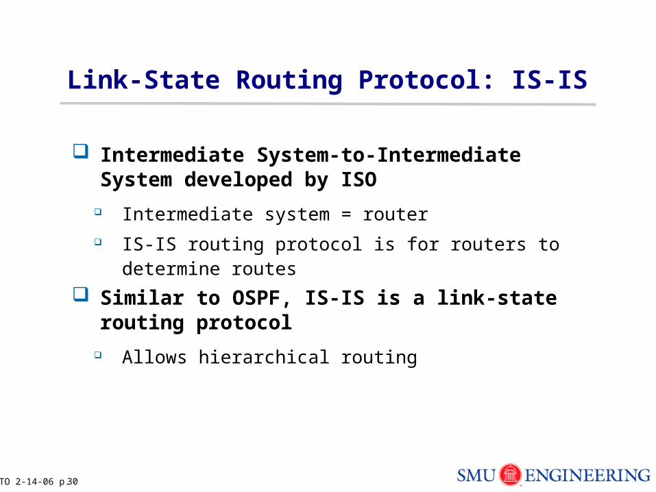
Link-State Routing Protocol: IS-IS
Intermediate System-to-Intermediate System developed by ISO
Intermediate system = router IS-IS routing protocol is for routers to determine routes
Similar to OSPF, IS-IS is a link-state routing protocol
Allows hierarchical routing
TO 2-14-06 p. 31
Spring 2006
EE 5304/EETS 7304 Internet Protocols
Tom OhDept of Electrical Engineering
Network protocols and congestion control: X.25, ATM
TO 2-14-06 p. 32
Outline
X.25
Sliding window congestion control
ATM (Comer: pg. 221-233)
Connection admission control
TO 2-14-06 p. 33
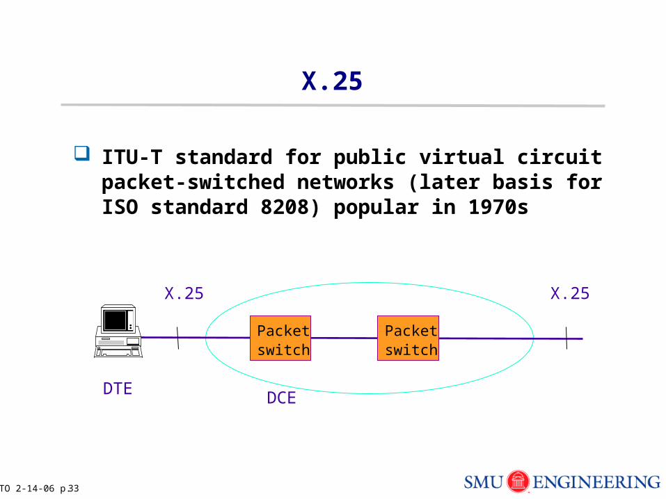
X.25
ITU-T standard for public virtual circuit packet-switched networks (later basis for ISO standard 8208) popular in 1970s
Packetswitch
Packetswitch
X.25 X.25
DTE DCE
TO 2-14-06 p. 34
X.25 (cont)
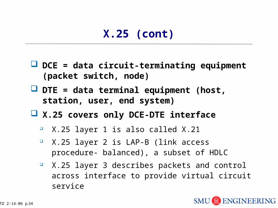
DCE = data circuit-terminating equipment (packet switch, node)
DTE = data terminal equipment (host, station, user, end system)
X.25 covers only DCE-DTE interface
X.25 layer 1 is also called X.21 X.25 layer 2 is LAP-B (link access procedure- balanced), a
subset of HDLC X.25 layer 3 describes packets and control across
interface to provide virtual circuit service
TO 2-14-06 p. 35
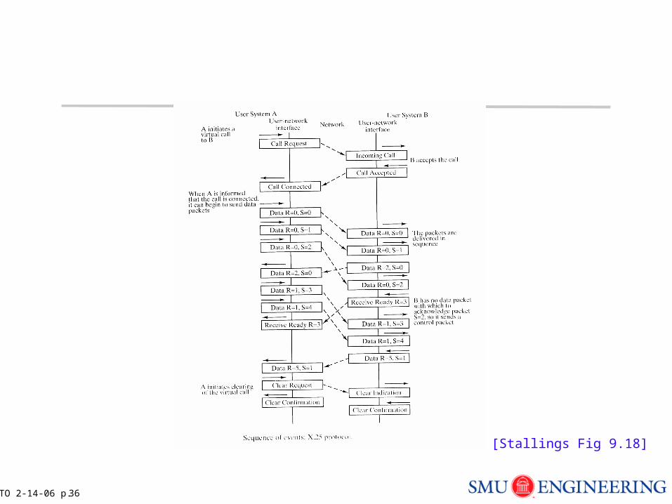
X.25 (cont)
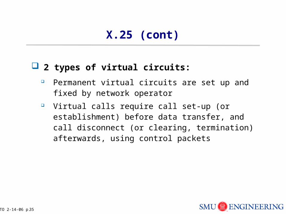
2 types of virtual circuits:
Permanent virtual circuits are set up and fixed by network operator
Virtual calls require call set-up (or establishment) before data transfer, and call disconnect (or clearing, termination) afterwards, using control packets
TO 2-14-06 p. 36
[Stallings Fig 9.18]
TO 2-14-06 p. 37
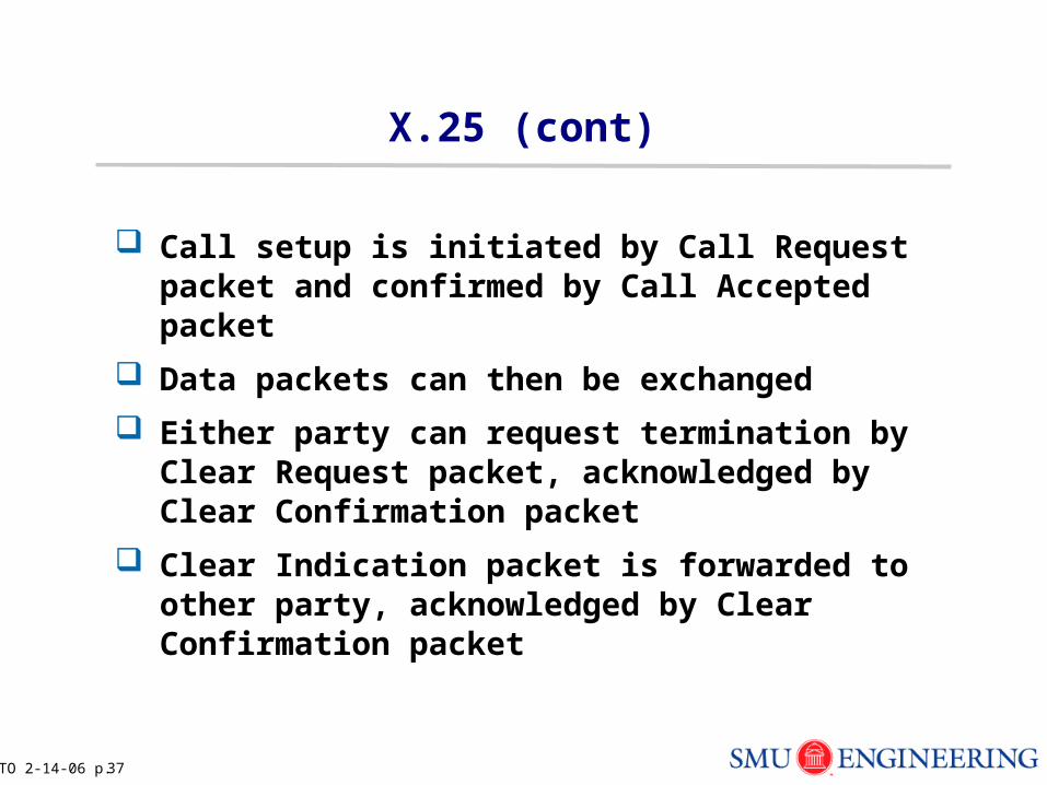
X.25 (cont)
Call setup is initiated by Call Request packet and confirmed by Call Accepted packet
Data packets can then be exchanged
Either party can request termination by Clear Request packet, acknowledged by Clear Confirmation packet
Clear Indication packet is forwarded to other party, acknowledged by Clear Confirmation packet
TO 2-14-06 p. 38
X.25 (cont)
Virtual circuits are identified uniquely by number contained in packet header
Local significance only, translated at each node Global VC numbers have disadvantages: limit number of
connections, and troublesome to find unused numbers
2 types of packets: data and control packets
TO 2-14-06 p. 39
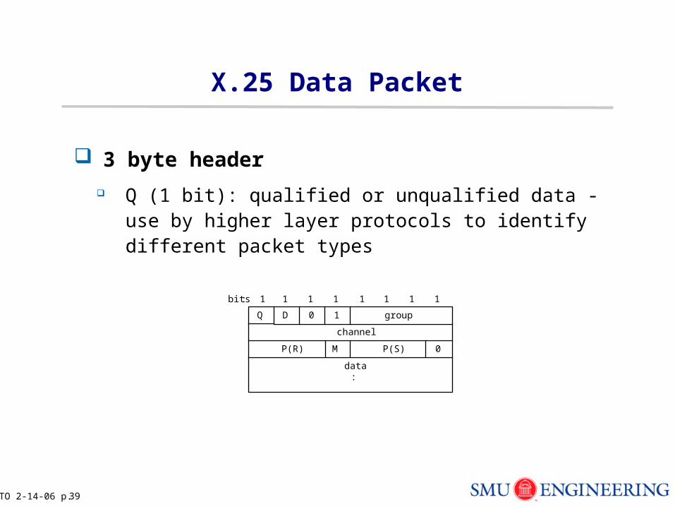
X.25 Data Packet
3 byte header
Q (1 bit): qualified or unqualified data - use by higher layer protocols to identify different packet types
bits:
Q
channel
1 1
priority
1 1 1 1 1 1
D 0 1 group
M P(S) 0P(R)
data :
TO 2-14-06 p. 40
X.25 Data Packet (cont)
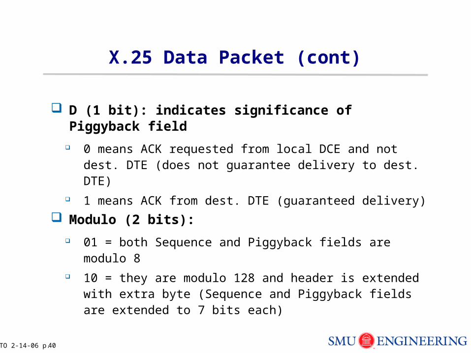
D (1 bit): indicates significance of Piggyback field
0 means ACK requested from local DCE and not dest. DTE (does not guarantee delivery to dest. DTE)
1 means ACK from dest. DTE (guaranteed delivery)
Modulo (2 bits):
01 = both Sequence and Piggyback fields are modulo 8 10 = they are modulo 128 and header is extended with
extra byte (Sequence and Piggyback fields are extended to 7 bits each)
TO 2-14-06 p. 41
X.25 Data Packet (cont)
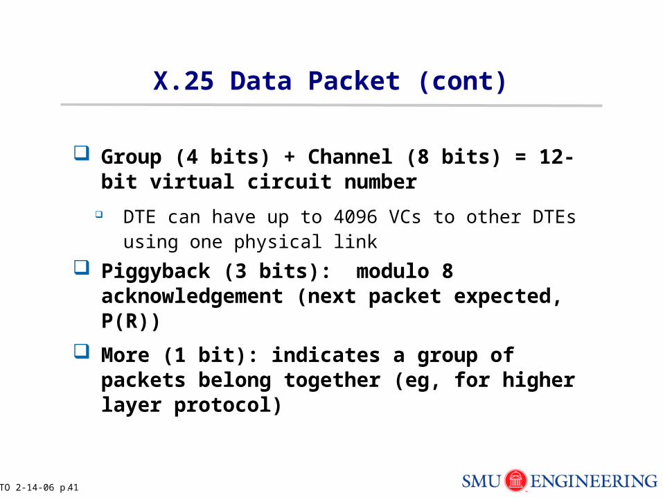
Group (4 bits) + Channel (8 bits) = 12-bit virtual circuit number
DTE can have up to 4096 VCs to other DTEs using one physical link
Piggyback (3 bits): modulo 8 acknowledgement (next packet expected, P(R))
More (1 bit): indicates a group of packets belong together (eg, for higher layer protocol)
TO 2-14-06 p. 42
X.25 Data Packet (cont)
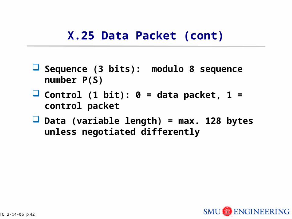
Sequence (3 bits): modulo 8 sequence number P(S)
Control (1 bit): 0 = data packet, 1 = control packet
Data (variable length) = max. 128 bytes unless negotiated differently
TO 2-14-06 p. 43
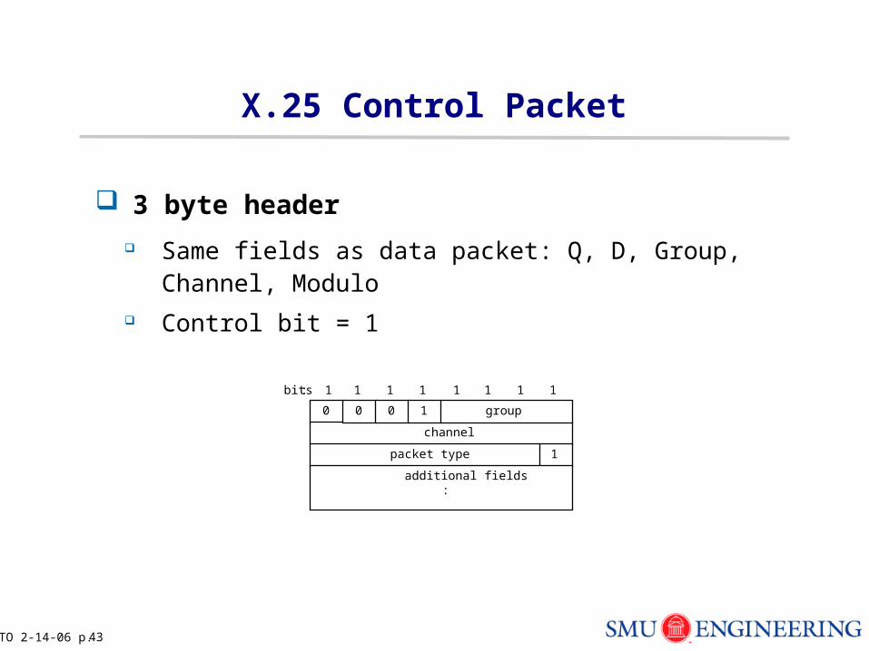
X.25 Control Packet
3 byte header
Same fields as data packet: Q, D, Group, Channel, Modulo
Control bit = 1
bits:
0
channel
1 1
priority
1 1 1 1 1 1
0 0 1 group
1packet type
additional fields :
TO 2-14-06 p. 44
X.25 Control Packet (cont)
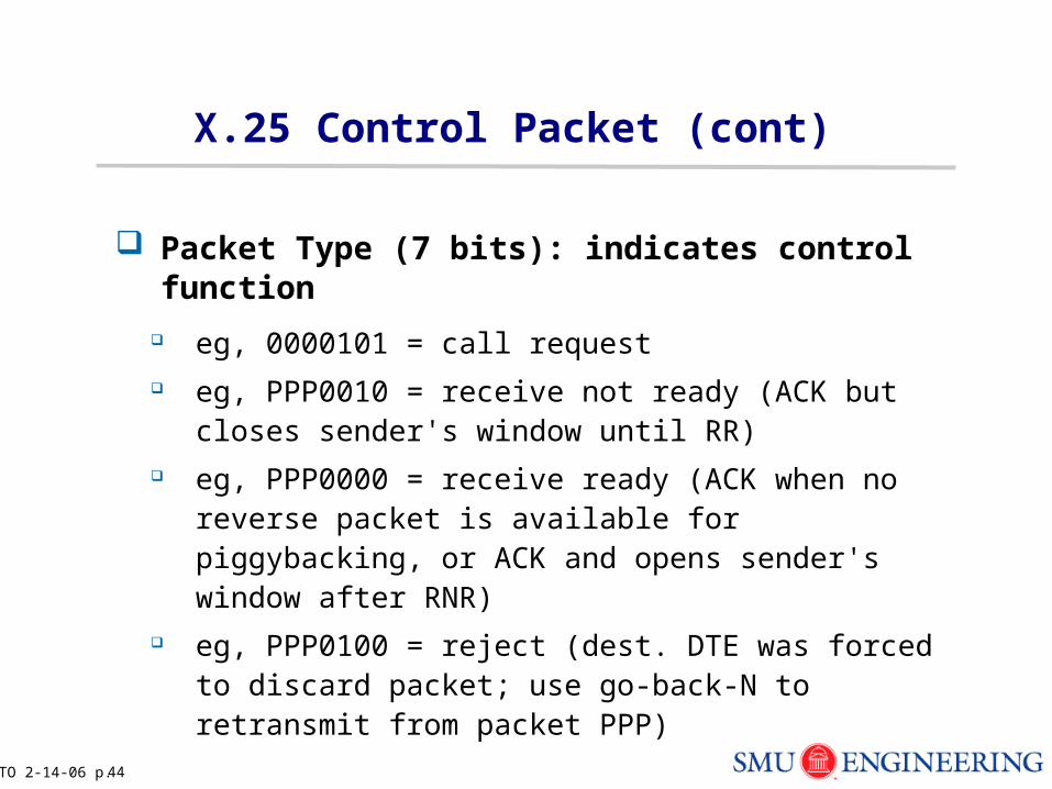
Packet Type (7 bits): indicates control function
eg, 0000101 = call request eg, PPP0010 = receive not ready (ACK but closes
sender's window until RR) eg, PPP0000 = receive ready (ACK when no reverse
packet is available for piggybacking, or ACK and opens sender's window after RNR)
eg, PPP0100 = reject (dest. DTE was forced to discard packet; use go-back-N to retransmit from packet PPP)
TO 2-14-06 p. 45
X.25 Control Packet (cont)
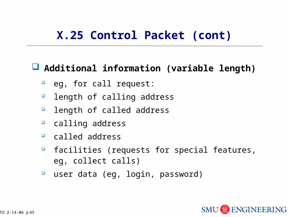
Additional information (variable length)
eg, for call request: length of calling address length of called address calling address called address facilities (requests for special features, eg, collect calls) user data (eg, login, password)
TO 2-14-06 p. 46
X.25 Congestion Control
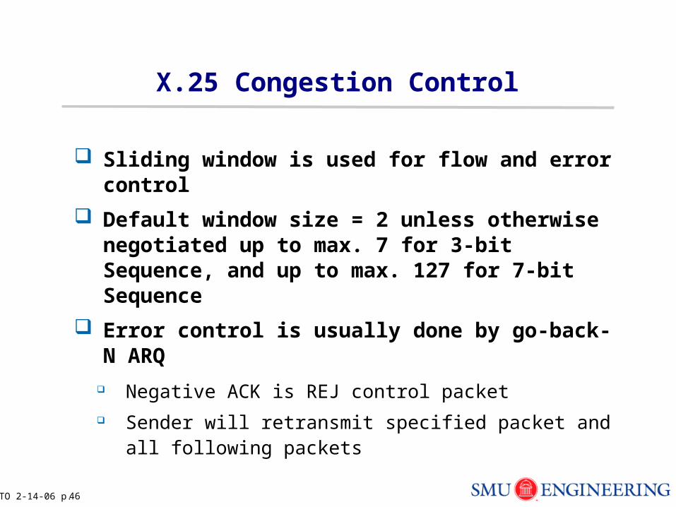
Sliding window is used for flow and error control
Default window size = 2 unless otherwise negotiated up to max. 7 for 3-bit Sequence, and up to max. 127 for 7-bit Sequence
Error control is usually done by go-back-N ARQ
Negative ACK is REJ control packet Sender will retransmit specified packet and all following
packets
TO 2-14-06 p. 47
Sliding Window Congestion Control
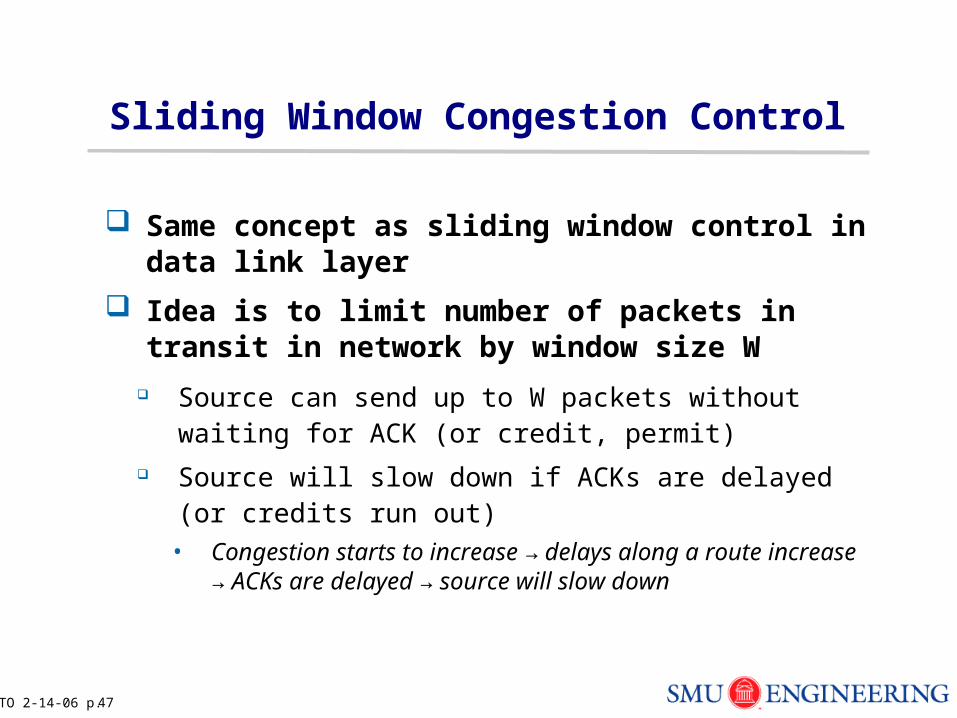
Same concept as sliding window control in data link layer
Idea is to limit number of packets in transit in network by window size W
Source can send up to W packets without waiting for ACK (or credit, permit)
Source will slow down if ACKs are delayed (or credits run out)
• Congestion starts to increase → delays along a route increase → ACKs are delayed → source will slow down
TO 2-14-06 p. 48
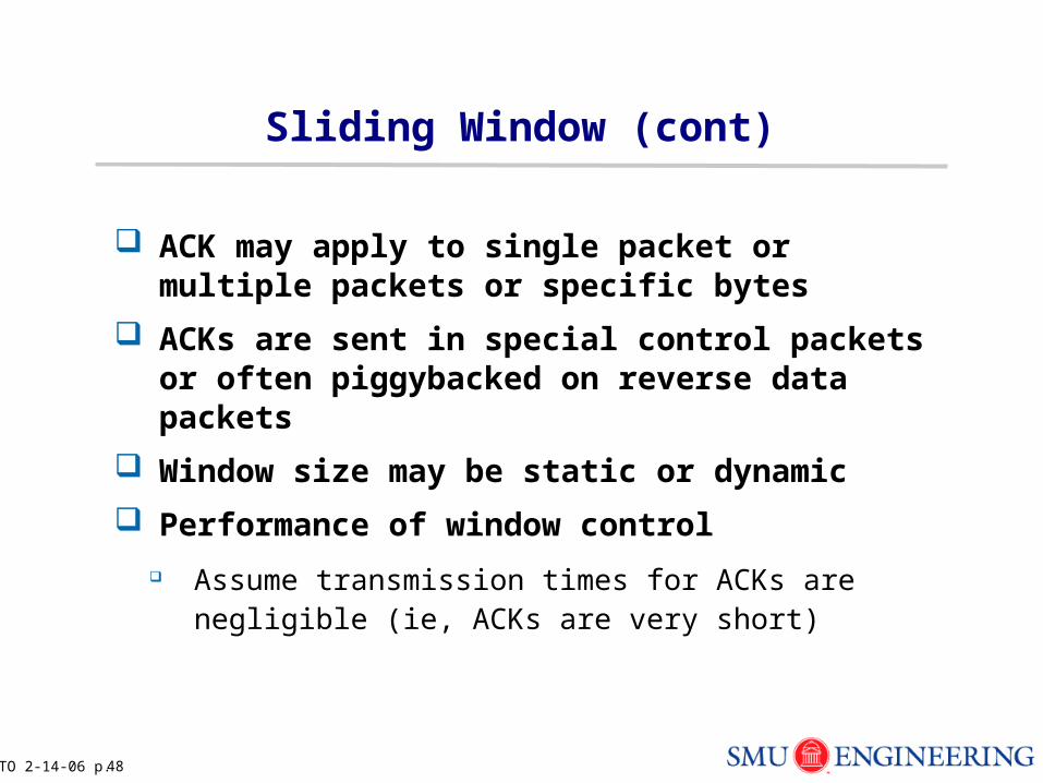
Sliding Window (cont)
ACK may apply to single packet or multiple packets or specific bytes
ACKs are sent in special control packets or often piggybacked on reverse data packets
Window size may be static or dynamic
Performance of window control
Assume transmission times for ACKs are negligible (ie, ACKs are very short)
TO 2-14-06 p. 49
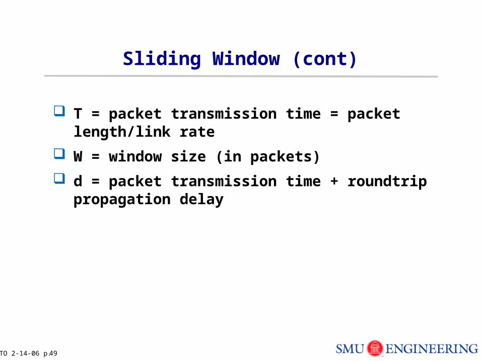
Sliding Window (cont)
T = packet transmission time = packet length/link rate
W = window size (in packets)
d = packet transmission time + roundtrip propagation delay
TO 2-14-06 p. 50
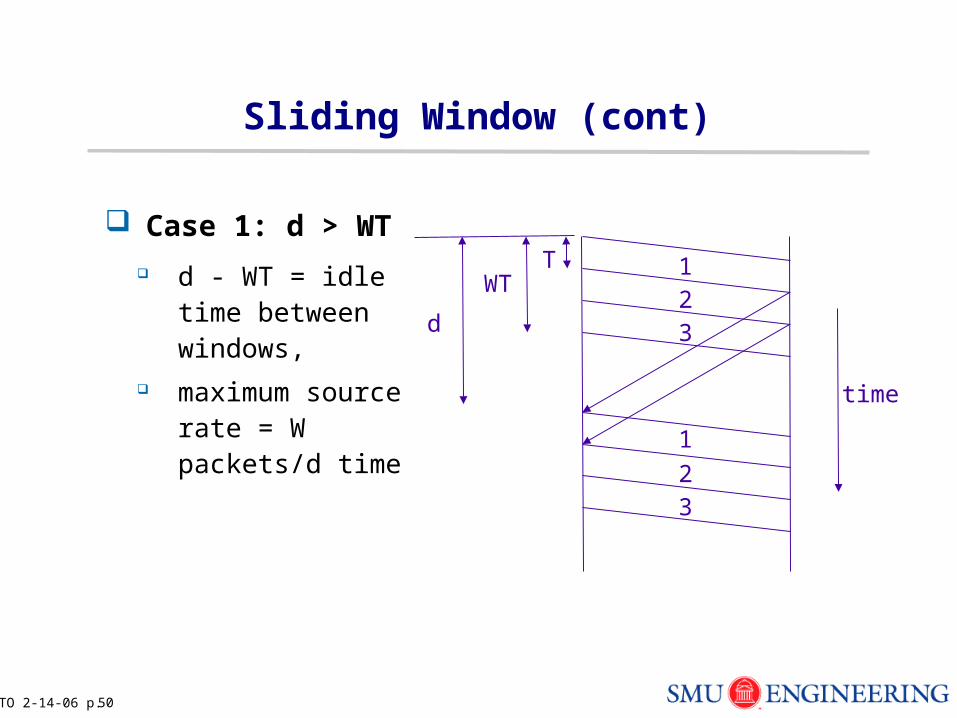
Sliding Window (cont)
Case 1: d > WT
d - WT = idle time between windows,
maximum source rate = W packets/d time
TWT
d
123
1
23
time
TO 2-14-06 p. 51
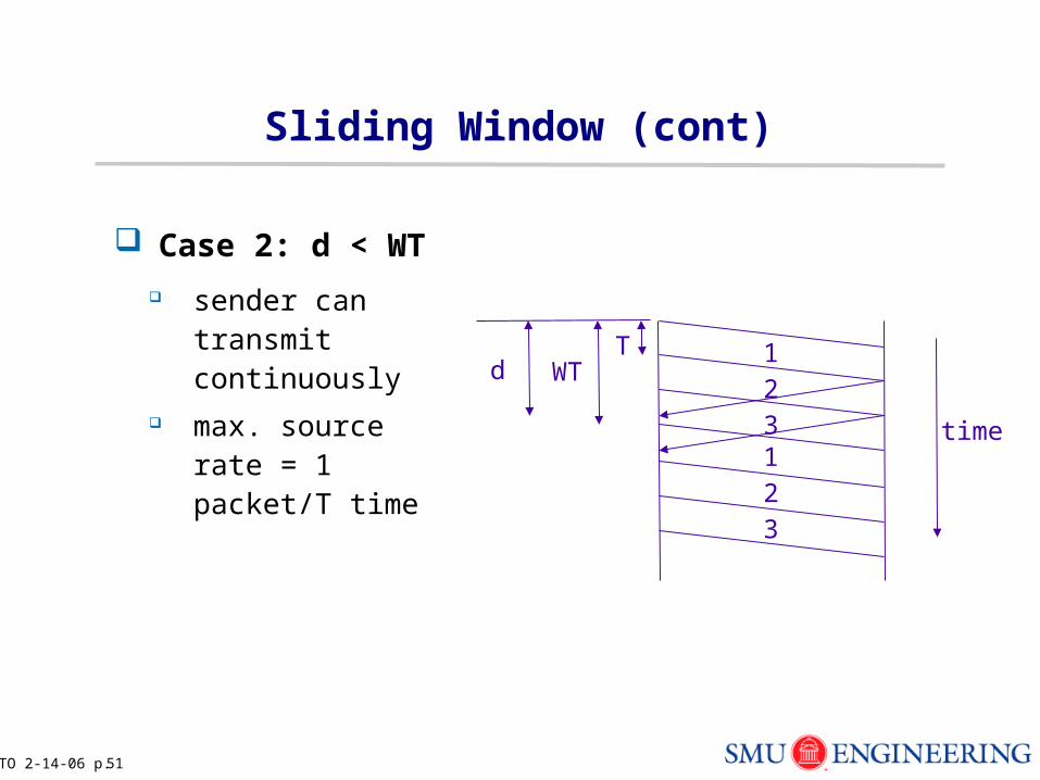
Sliding Window (cont)
Case 2: d < WT
sender can transmit continuously
max. source rate = 1 packet/T time
TWTd
123123
time
TO 2-14-06 p. 52
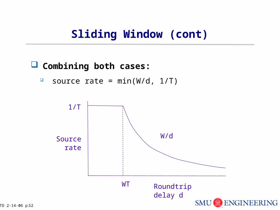
Sliding Window (cont)
Combining both cases:
source rate = min(W/d, 1/T)
1/T
Sourcerate
WT Roundtrip delay d
W/d
TO 2-14-06 p. 53
Sliding Window (cont)
Source will slow down when congestion causes long roundtrip delays
Source will automatically stop within W packet transmission times (if no ACKs returned)
Trade-off between response time (want W small to slow down a source quickly) and efficiency (want W > d/T so source can transmit continuously)
TO 2-14-06 p. 54
OPNET
Login into linux or solaris machine
At prompt, type opnet
The first time a user runs OPNET, two directories are created:<opnet_user_home>\op_admin<opnet_user_home>\op_models
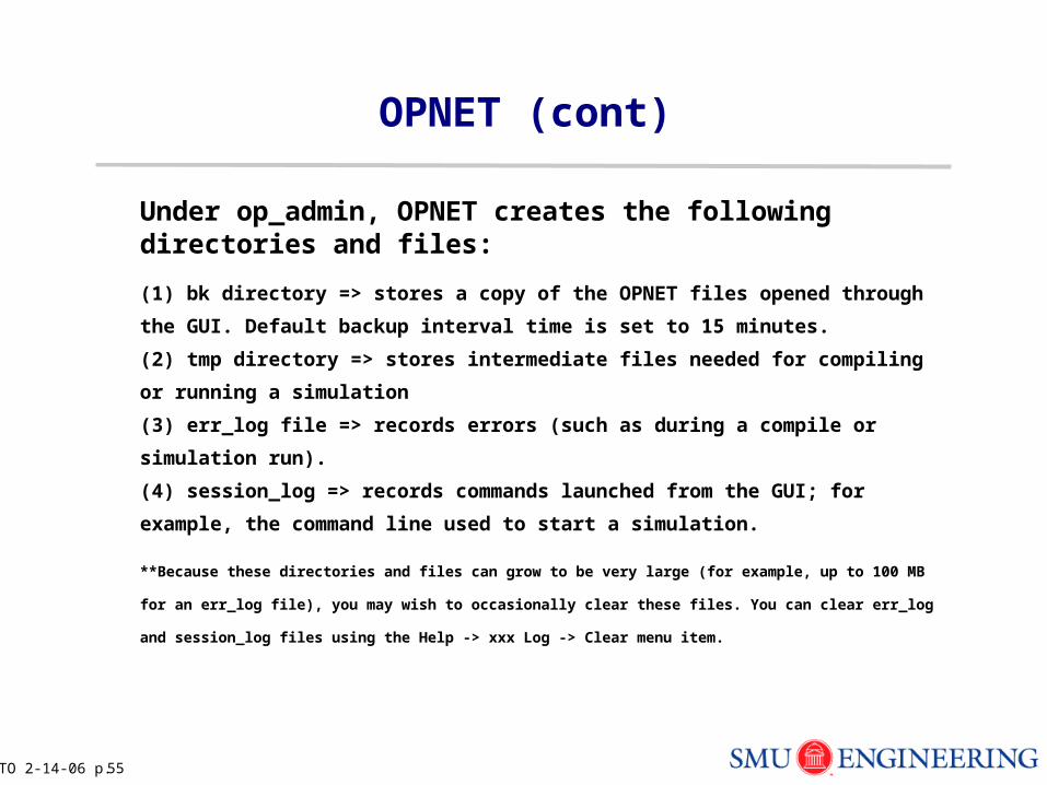
Under op_admin, OPNET creates the following directories and files:
TO 2-14-06 p. 55
OPNET (cont)
Under op_admin, OPNET creates the following directories and files:
(1) bk directory => stores a copy of the OPNET files opened through the GUI.
Default backup interval time is set to 15 minutes.
(2) tmp directory => stores intermediate files needed for compiling or running
a simulation
(3) err_log file => records errors (such as during a compile or simulation run).
(4) session_log => records commands launched from the GUI; for example,
the command line used to start a simulation.
**Because these directories and files can grow to be very large (for example, up to 100 MB for an
err_log file), you may wish to occasionally clear these files. You can clear err_log and session_log files
using the Help -> xxx Log -> Clear menu item.
TO 2-14-06 p. 56
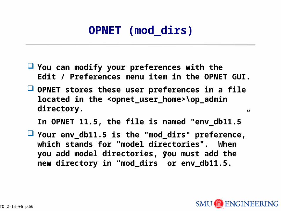
OPNET (mod_dirs)
You can modify your preferences with the Edit / Preferences menu item in the OPNET GUI.
OPNET stores these user preferences in a file located in the <opnet_user_home>\op_admin directory.
In OPNET 11.5, the file is named "env_db11.5”
Your env_db11.5 is the "mod_dirs" preference, which stands for "model directories". When you add model directories, you must add the new directory in “mod_dirs” or env_db11.5.