Embed Size (px)
Citation preview
SPRING-ACTUATEDBRAKESELECTROMAGNETIC CLUTCHES & BRAKES
SPRING-ACTUATED BRAKES
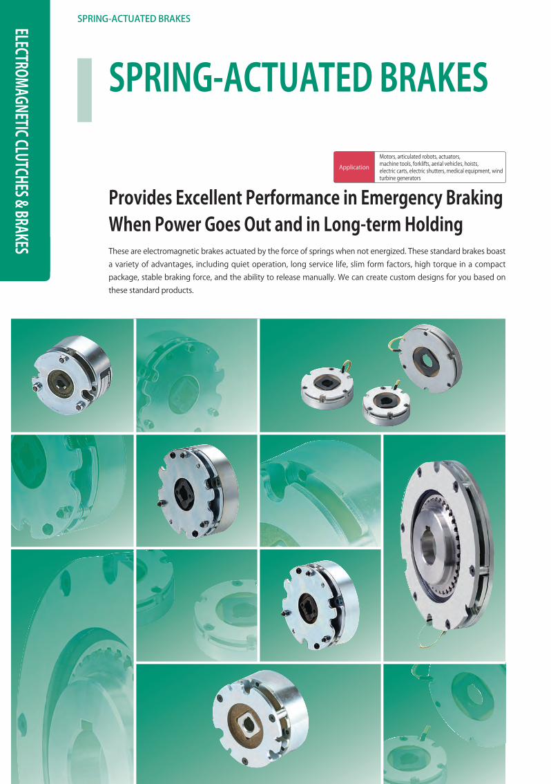
Provides Excellent Performance in Emergency BrakingWhen Power Goes Out and in Long-term HoldingThese are electromagnetic brakes actuated by the force of springs when not energized. These standard brakes boast a variety of advantages, including quiet operation, long service life, slim form factors, high torque in a compact package, stable braking force, and the ability to release manually. We can create custom designs for you based on these standard products.
Application
Motors, articulated robots, actuators,machine tools, forklifts, aerial vehicles, hoists,electric carts, electric shutters, medical equipment, wind turbine generators
333
333
SERIES
ELECTROMAGNETIC-ACTUATED CLUTCHES AND BRAKES
ELECTROMAGNETIC-ACTUATED MICRO CLUTCHES & BRAKES
ELECTROMAGNETIC-ACTUATEDCLUTCHES & BRAKES
ELECTROMAGNETIC CLUTCH & BRAKE UNITS
SPRING-ACTUATEDBRAKE
ELECTROMAGNETIC TOOTH CLUTCHES
BRAKE MOTORS
POWER SUPPLIES
MODELS
BXW
BXR
BXL
BXH
BXL-N
COUPLINGS
ETP BUSHINGS
ELECTROMAGNETIC CLUTCHES & BRAKES
SPEED CHANGERS & REDUCERS
INVERTERS
LINEAR SHAFT DRIVES
TORQUE LIMITERS
ROSTA
Models/Type
Mountingmethod
Torque [N·m]Release
leverDust cover Slim
Quiet mechanism
Reduced aperiodic
noise
Reduced armature
pull-in noise
Reduced braking
noise
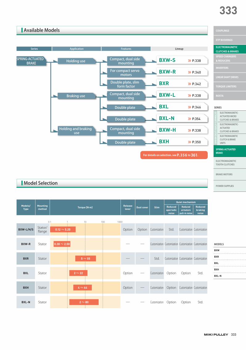
BXW-L/H/S Stator/fl ange Option Option Customization Std. Customization Customization
BXW-R Stator ─ ─ Customization Customization Customization Customization
BXR Stator ─ ─ Std. Customization Customization Customization
BXL Stator Option ─ Customization Option Option Std.
BXH Stator Option ─ Customization Option Customization Customization
BXL-N Stator ─ ─ Customization Option Option Std.
Series Application Features Lineup
AvailableModels
For details on selection, see P. 356 to 361.
SPRING-ACTUATEDBRAKE
BXW-S P.338
○○○○○ P.000○○○○○ P.000BXW-L P.338
BXW-H P.338
BXW-R P.340
○○○○○ P.000○○○○○ P.000BXL P.346
BXH P.350
BXR P.342
○○○○○ P.000○○○○○ P.000BXL-N P.354
Holdinguse
○○○○○○○○○○○○○○○○○○Brakinguse
Holdingandbrakinguse
Compact,dualsidemounting
○○○○○○○○○○○○○○○○○○Compact,dualsidemounting
Compact,dualsidemounting
Forcompactservomotors
○○○○○○○○○○○○○○○○○○Doubleplate
Doubleplate
Doubleplate,slimformfactor
○○○○○○○○○○○○○○○○○○Doubleplate
ModelSelection
0.1 1 10 100 1000
0.12 ~ 5.20
0.30 ~ 2.50
5 ~ 55
4 ~ 44
2 ~ 22
2 ~ 80
334
SPRING-ACTUATEDBRAKESELECTROMAGNETIC CLUTCHES & BRAKES
BX W-L /H/S
BX W-R
BXR
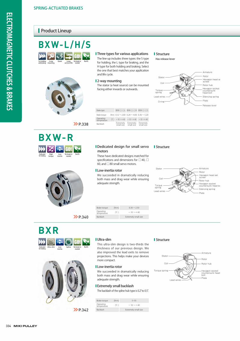
Brake type BXW- □ - □ L BXW- □ - □ H BXW- □ - □ S
Brake torque [N·m] 0.12 〜 2.00 0.24 〜 4.00 0.36 〜 5.20
Operating temperature [℃ ] ー 10 〜+ 40 ー 10 〜+ 40 ー 10 〜+ 40
Backlash Extremely small size
Extremely small size
Extremely small size
Brake torque [N·m] 0.30 〜 2.50
Operating temperature [℃ ] ー 10 〜+ 40
Backlash Extremely small size
■ Structure Hasreleaselever
Stator
Armature
RotorHexagon head set screw
Rotor hubHexagon socket countersunk head bolt
Silencing spring
Plate
Release lever
Coil
Torquespring
O-ring
Lead wires
■ Structure
Stator Armature
RotorHexagon head set screwRotor hubHexagon socket countersunk head boltSilencing spring
Plate
Coil
Torquespring
Lead wires
■ Structure
StatorArmature
Rotor
Rotor hub
Hexagon socket countersunk head boltPlate
Coil
Torque spring
Lead wires
■ThreetypesforvariousapplicationsThe line-up includes three types: the S type for holding, the L type for braking, and the H type for both holding and braking. Select the one that best matches your application and life cycle.
■2-waymountingThe stator (a heat source) can be mounted facing either inwards or outwards.
■DedicateddesignforsmallservomotorsThese have dedicated designs matched for specifications and dimensions for □ 40, □60, and □80 small servo motors.
■Low-inertiarotorWe succeeded in dramatically reducing both mass and drag wear while ensuring adequate strength.
■Ultra-slimThis ultra-slim design is two-thirds the thickness of our previous design. We also improved the lead exits to remove projections. This helps make your devices more compact.
■Low-inertiarotorWe succeeded in dramatically reducing both mass and drag wear while ensuring adequate strength.
■ExtremelysmallbacklashThe backlash of the spline hub type is 0.2° to 0.5°.
Brake torque [N·m] 5~55
Operating temperature [℃ ] ー 10 〜+ 40
Backlash Extremely small size
Lowinertia
Hightorque
RoHSDedicatedforholding
Nobreak-inneeded
Lowinertia
RoHSDedicatedforholding
Nobreak-inneeded
Ultra-slim Spline
P.338
P.340
P.342
ProductLineup
Quiet RoHSForholdingandbraking
2-waymounting
Nobreak-inneeded
Longservicelife
335
335
SERIES
ELECTROMAGNETIC-ACTUATED CLUTCHES AND BRAKES
ELECTROMAGNETIC-ACTUATED MICRO CLUTCHES & BRAKES
ELECTROMAGNETIC-ACTUATEDCLUTCHES & BRAKES
ELECTROMAGNETIC CLUTCH & BRAKE UNITS
SPRING-ACTUATEDBRAKE
ELECTROMAGNETIC TOOTH CLUTCHES
BRAKE MOTORS
POWER SUPPLIES
MODELS
BXW
BXR
BXL
BXH
BXL-N
COUPLINGS
ETP BUSHINGS
ELECTROMAGNETIC CLUTCHES & BRAKES
SPEED CHANGERS & REDUCERS
INVERTERS
LINEAR SHAFT DRIVES
TORQUE LIMITERS
ROSTA
BXL
BXL-N
BXH
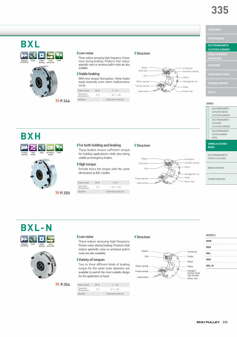
■ Structure
Stator Armature
Rotor
Rotor hub
Hexagonal nut
Auxiliary spring
Plate
Stud bolt
Coil
Torque spring
Rotor spring
Lead wires
■ Structure
Stator
Coil
Torque spring
Rotor spring
Lead wires
Armature
Collar
Rotor
Plate
Hexagon Socket Head Cap ScrewsRotor hub
■ Structure
Stator Armature
Rotor
Rotor hub
Hexagonal nut
Auxiliary spring
Plate
Stud bolt
Coil
Torque spring
Lead wires
■LownoiseThese reduce annoying high-frequency friction noise during braking. Products that reduce aperiodic noise or armature pull-in noise are also available.
■StablebrakingWith low torque fluctuation, these brake loads instantly even when malfunctions occur.
■LownoiseThese reduce annoying high-frequency friction noise during braking. Products that reduce aperiodic noise or armature pull-in noise are also available.
■VarietyoftorquesTwo to three different kinds of braking torque for the same outer diameter are available to permit the most suitable design for the application at hand.
■ForbothholdingandbrakingThese brakes ensure sufficient torque for holding applications while also being usable as emergency brakes.
■HightorqueProvide twice the torque with the same dimensions as BXL models.
Brake torque [N·m] 4~44
Operating temperature [℃ ] ー 10 〜+ 40
Backlash Extremely small size
Brake torque [N·m] 2 〜 22
Operating temperature [℃ ] ー 10 〜+ 40
Backlash Extremely small size
Brake torque [N·m] 2 〜 80
Operating temperature [℃ ] 0 〜+ 40
Backlash Extremely small size
Hightorque
Quiet RoHSForholdingandbraking
Nobreak-inneeded
Quiet
Quiet
RoHSDedicatedforbraking
Dedicatedforbraking
Longservicelife
Longservicelife
Stablebraking
Stablebraking
P.346
P.350
P.354
336
SPRING-ACTUATED BRAKESELECTROMAGNETIC CLUTCHES & BRAKES
CustomizationExamples
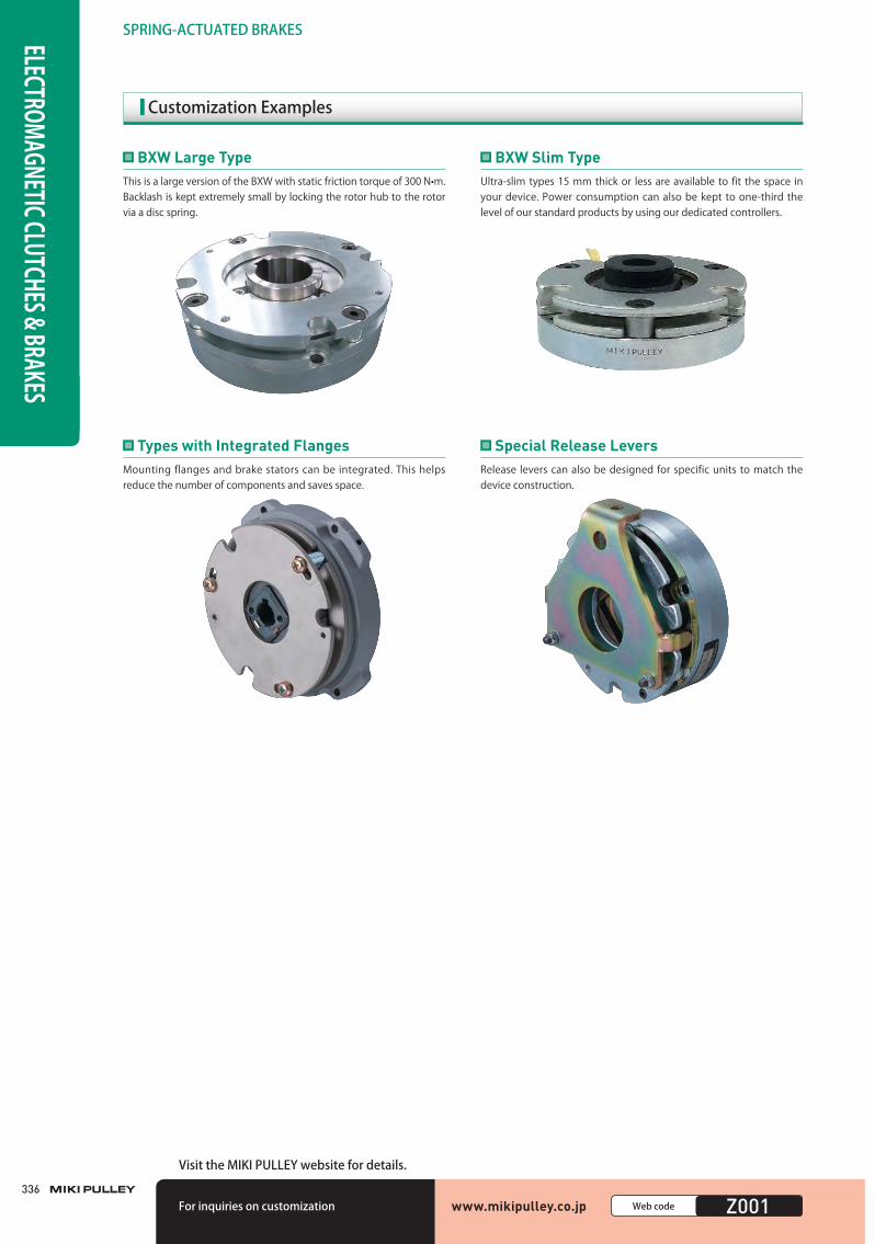
This is a large version of the BXW with static friction torque of 300 N•m.Backlash is kept extremely small by locking the rotor hub to the rotor via a disc spring.
BXW Large TypeUltra-slim types 15 mm thick or less are available to fit the space in your device. Power consumption can also be kept to one-third the level of our standard products by using our dedicated controllers.
BXW Slim Type
Mounting flanges and brake stators can be integrated. This helps reduce the number of components and saves space.
Types with Integrated FlangesRelease levers can also be designed for specific units to match the device construction.
Special Release Levers
www.mikipulley.co.jp 0000Webcode Z001Forinquiriesoncustomization
VisittheMIKIPULLEYwebsitefordetails.
337
337
SERIES
ELECTROMAGNETIC-ACTUATED CLUTCHES AND BRAKES
ELECTROMAGNETIC-ACTUATED MICRO CLUTCHES & BRAKES
ELECTROMAGNETIC-ACTUATEDCLUTCHES & BRAKES
ELECTROMAGNETIC CLUTCH & BRAKE UNITS
SPRING-ACTUATEDBRAKE
ELECTROMAGNETIC TOOTH CLUTCHES
BRAKE MOTORS
POWER SUPPLIES
MODELS
BXW
BXR
BXL
BXH
BXL-N
COUPLINGS
ETP BUSHINGS
ELECTROMAGNETIC CLUTCHES & BRAKES
SPEED CHANGERS & REDUCERS
INVERTERS
LINEAR SHAFT DRIVES
TORQUE LIMITERS
ROSTA
FAQ
Q1 I don't see anything with the torque and response I need in your standard products. Can you customize something for me?
We can customize units in many ways: outfitting them for
overexcitation power supplies or use of inrush current at
motor startup, changing the frictional material, boosting
torque, increasing response, extending the total energy
(service life), suppressing heat generation, and more. Consult
Miki Pulley for details.
A
Q2 Can you handle cases in which standard products cannot be installed due to dimensional constraints?
Yes, we can. For example, we have a long track record creating slimmer units that deliver the same torque. These units can provide the same torque while being only about half as thick as the standard product, although this will vary with your conditions. Consult Miki Pulley for details.
A
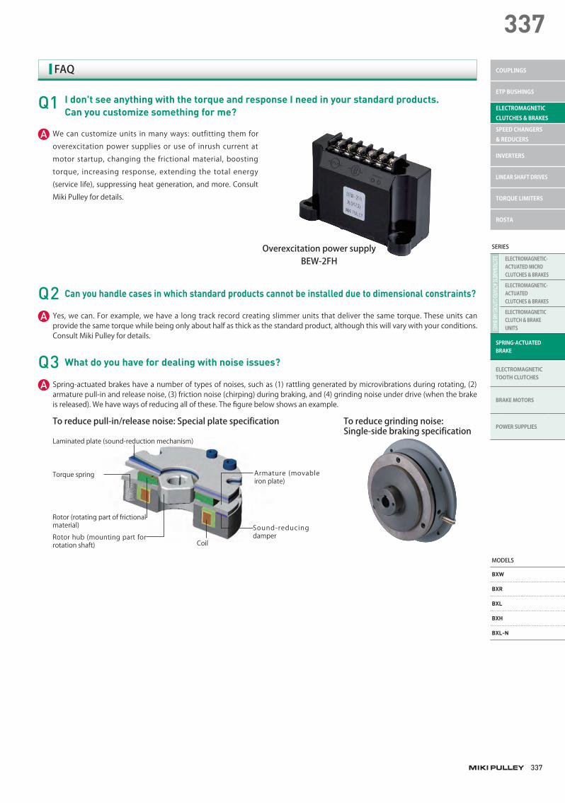
Q3 What do you have for dealing with noise issues?
Spring-actuated brakes have a number of types of noises, such as (1) rattling generated by microvibrations during rotating, (2) armature pull-in and release noise, (3) friction noise (chirping) during braking, and (4) grinding noise under drive (when the brake is released). We have ways of reducing all of these. The figure below shows an example.
A
Toreducegrindingnoise:Single-sidebrakingspecification
Toreducepull-in/releasenoise:Specialplatespecification
Torque spring Armature (movable iron plate)
Sound-reducing damper
Coil
OverexcitationpowersupplyBEW-2FH
www.mikipulley.co.jp
Rotor hub (mounting part for rotation shaft)
Laminated plate (sound-reduction mechanism)
Rotor (rotating part of frictional material)
346346
SPRING-ACTUATEDBRAKESELECTROMAGNETIC CLUTCHES & BRAKES
BXL Models
Model
Size
Static frictiontorque
Ts [N·m]
Coil (at 20℃ )Heat
resistance class
Max.rotation
speed[min-1]
Rotating partmoment of
inertiaJ [kg·m2]
Allowable braking
energy ratePbaℓ [W]
Total braking energy
ET [J]
Armaturepull-in time
ta [s]
Armaturerelease time
tar [s]
Mass[kg]Voltage
[V]Wattage
[W]Current
[A]Resistance
[ Ω ]
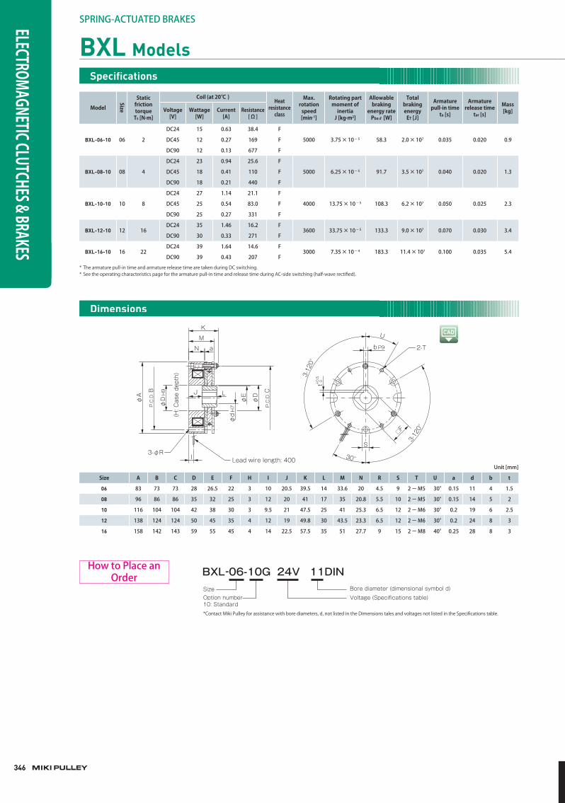
BXL-06-10 06 2
DC24 15 0.63 38.4 F
5000 3.75×10⁻⁵ 58.3 2.0×10⁷ 0.035 0.020 0.9DC45 12 0.27 169 F
DC90 12 0.13 677 F
BXL-08-10 08 4
DC24 23 0.94 25.6 F
5000 6.25×10⁻⁵ 91.7 3.5×10⁷ 0.040 0.020 1.3DC45 18 0.41 110 F
DC90 18 0.21 440 F
BXL-10-10 10 8
DC24 27 1.14 21.1 F
4000 13.75×10⁻⁵ 108.3 6.2×10⁷ 0.050 0.025 2.3DC45 25 0.54 83.0 F
DC90 25 0.27 331 F
BXL-12-10 12 16DC24 35 1.46 16.2 F
3600 33.75×10⁻⁵ 133.3 9.0×10⁷ 0.070 0.030 3.4DC90 30 0.33 271 F
BXL-16-10 16 22DC24 39 1.64 14.6 F
3000 7.35×10⁻⁴ 183.3 11.4×10⁷ 0.100 0.035 5.4DC90 39 0.43 207 F
* The armature pull-in time and armature release time are taken during DC switching.* See the operating characteristics page for the armature pull-in time and release time during AC-side switching (half-wave rectifi ed).
K
M
N a
φD
H9
φA
P.C
.D.B
I Lead wire length: 4003-φR
φD
P.C
.D.C
φE
φd
H7
(H: C
ase
dept
h) 3-12
0°
3-12
0°
30°
U
2-T
□F
S
J L
t 0+0.
5
b P9
Size A B C D E F H I J K L M N R S T U a d b t
06 83 73 73 28 26.5 22 3 10 20.5 39.5 14 33.6 20 4.5 9 2-M5 30° 0.15 11 4 1.5
08 96 86 86 35 32 25 3 12 20 41 17 35 20.8 5.5 10 2-M5 30° 0.15 14 5 2
10 116 104 104 42 38 30 3 9.5 21 47.5 25 41 25.3 6.5 12 2-M6 30° 0.2 19 6 2.5
12 138 124 124 50 45 35 4 12 19 49.8 30 43.5 23.3 6.5 12 2-M6 30° 0.2 24 8 3
16 158 142 143 59 55 45 4 14 22.5 57.5 35 51 27.7 9 15 2-M8 40° 0.25 28 8 3
Unit[mm]
Specifi cations
Dimensions
Voltage (Specifications table)Bore diameter (dimensional symbol d)Size
Option number10: Standard*Contact Miki Pulley for assistance with bore diameters, d, not listed in the Dimensions tales and voltages not listed in the Specifications table.
BXL-06-10G 24V 11DINHowtoPlaceanOrder
347
347
347
SERIES
ELECTROMAGNETIC-ACTUATED CLUTCHES AND BRAKES
ELECTROMAGNETIC-ACTUATED MICRO CLUTCHES & BRAKES
ELECTROMAGNETIC-ACTUATEDCLUTCHES & BRAKES
ELECTROMAGNETIC CLUTCH & BRAKE UNITS
SPRING-ACTUATEDBRAKE
ELECTROMAGNETIC TOOTH CLUTCHES
BRAKE MOTORS
POWER SUPPLIES
MODELS
BXW
BXR
BXL
BXH
BXL-N
COUPLINGS
ETP BUSHINGS
ELECTROMAGNETIC CLUTCHES & BRAKES
SPEED CHANGERS & REDUCERS
INVERTERS
LINEAR SHAFT DRIVES
TORQUE LIMITERS
ROSTA
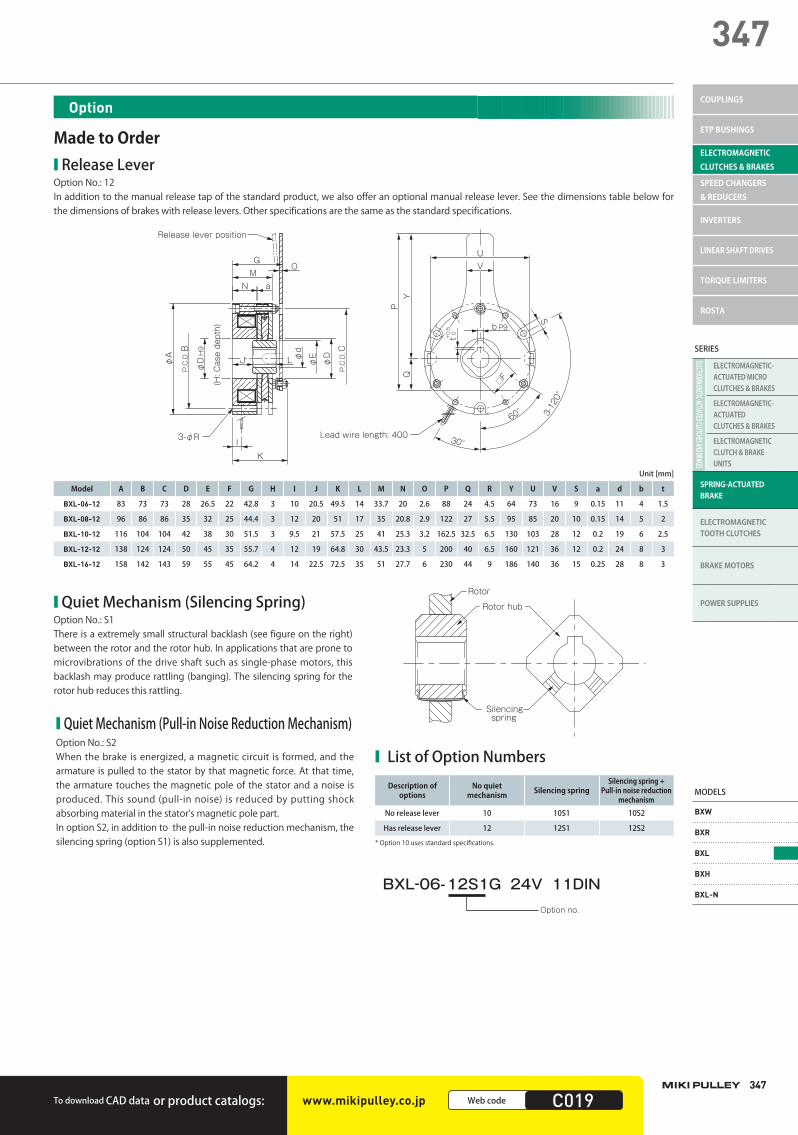
■ ReleaseLeverOption No.: 12In addition to the manual release tap of the standard product, we also offer an optional manual release lever. See the dimensions table below for the dimensions of brakes with release levers. Other specifications are the same as the standard specifications.
GM
N a
Release lever position
φD
H9
φA
(H: C
ase
dept
h)
I
O
3-φR
K
J L φD
P.C
.D.C
P.C
.D.B
φEφ
d
Lead wire length: 400
UV
QY
P
S
30°
3-12
0°
60°
□F
t 0
+0.
5 b P9
Model A B C D E F G H I J K L M N O P Q R Y U V S a d b t
BXL-06-12 83 73 73 28 26.5 22 42.8 3 10 20.5 49.5 14 33.7 20 2.6 88 24 4.5 64 73 16 9 0.15 11 4 1.5
BXL-08-12 96 86 86 35 32 25 44.4 3 12 20 51 17 35 20.8 2.9 122 27 5.5 95 85 20 10 0.15 14 5 2
BXL-10-12 116 104 104 42 38 30 51.5 3 9.5 21 57.5 25 41 25.3 3.2 162.5 32.5 6.5 130 103 28 12 0.2 19 6 2.5
BXL-12-12 138 124 124 50 45 35 55.7 4 12 19 64.8 30 43.5 23.3 5 200 40 6.5 160 121 36 12 0.2 24 8 3
BXL-16-12 158 142 143 59 55 45 64.2 4 14 22.5 72.5 35 51 27.7 6 230 44 9 186 140 36 15 0.25 28 8 3
Unit[mm]
■ QuietMechanism(SilencingSpring)Option No.: S1There is a extremely small structural backlash (see figure on the right) between the rotor and the rotor hub. In applications that are prone to microvibrations of the drive shaft such as single-phase motors, this backlash may produce rattling (banging). The silencing spring for the rotor hub reduces this rattling.
■ QuietMechanism(Pull-inNoiseReductionMechanism)Option No.: S2When the brake is energized, a magnetic circuit is formed, and the armature is pulled to the stator by that magnetic force. At that time, the armature touches the magnetic pole of the stator and a noise is produced. This sound (pull-in noise) is reduced by putting shock absorbing material in the stator's magnetic pole part.In option S2, in addition to the pull-in noise reduction mechanism, the silencing spring (option S1) is also supplemented.
Silencingspring
Rotor hub
Rotor
■ ListofOptionNumbers
Description of options
No quiet mechanism Silencing spring
Silencing spring + Pull-in noise reduction
mechanismNoreleaselever 10 10S1 10S2
Hasreleaselever 12 12S1 12S2
* Option 10 uses standard specifi cations.
Option no.
BXL-06-12S1G 24V 11DIN
Option
Made to Order
TodownloadCADdata orproductcatalogs: www.mikipulley.co.jp 0000Webcode C019
348348
SPRING-ACTUATEDBRAKESELECTROMAGNETIC CLUTCHES & BRAKES
■ PrecautionsforHandling■BrakesMost electromagnetic braking systems are made using flexible materials. Be careful when handling such parts and materials as striking or dropping them or applying excessive force could cause them to become damaged or deformed.
■LeadWiresBe careful not to pull excessively on the brake lead wires, bend them at sharp angles, or allow them to hang too low.
■ PrecautionsforMounting■AffixingtheRotorHubAffix the rotor hub to the shaft with bolts, snap rings, or the like such that the rotor hub does not touch the armature or stator.
■BoltsandScrewsImplement screw-locking measures such as use of an adhesive thread-locking compound to bolts and screws used to install brakes.
■ShaftsThe shaft tolerance should be h6 or js6 class (JIS B 0401).
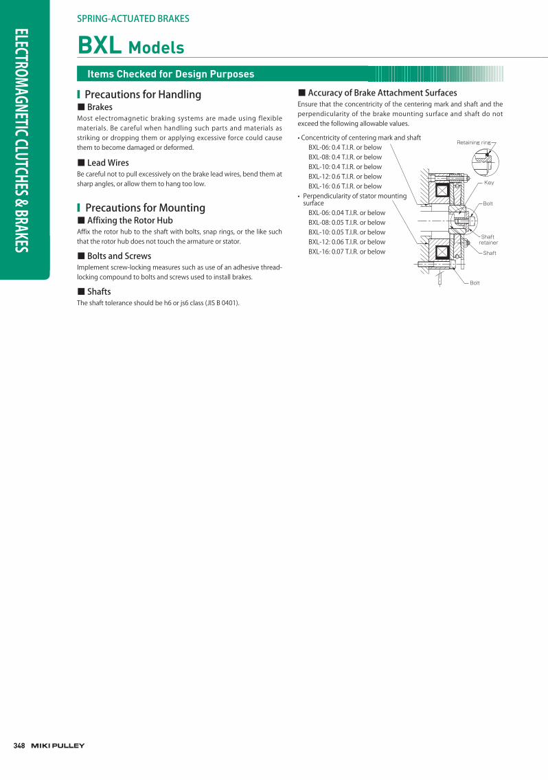
■AccuracyofBrakeAttachmentSurfacesEnsure that the concentricity of the centering mark and shaft and the perpendicularity of the brake mounting surface and shaft do not exceed the following allowable values.
• Concentricity of centering mark and shaft BXL-06: 0.4 T.I.R. or below BXL-08: 0.4 T.I.R. or below BXL-10: 0.4 T.I.R. or below BXL-12: 0.6 T.I.R. or below BXL-16: 0.6 T.I.R. or below
• Perpendicularity of stator mounting surface BXL-06: 0.04 T.I.R. or below BXL-08: 0.05 T.I.R. or below BXL-10: 0.05 T.I.R. or below BXL-12: 0.06 T.I.R. or below BXL-16: 0.07 T.I.R. or below
Retaining ring
Key
Bolt
Bolt
Shaft retainer
Shaft
BXL ModelsItems Checked for Design Purposes
349
349
349
SERIES
ELECTROMAGNETIC-ACTUATED CLUTCHES AND BRAKES
ELECTROMAGNETIC-ACTUATED MICRO CLUTCHES & BRAKES
ELECTROMAGNETIC-ACTUATEDCLUTCHES & BRAKES
ELECTROMAGNETIC CLUTCH & BRAKE UNITS
SPRING-ACTUATEDBRAKE
ELECTROMAGNETIC TOOTH CLUTCHES
BRAKE MOTORS
POWER SUPPLIES
MODELS
BXW
BXR
BXL
BXH
BXL-N
COUPLINGS
ETP BUSHINGS
ELECTROMAGNETIC CLUTCHES & BRAKES
SPEED CHANGERS & REDUCERS
INVERTERS
LINEAR SHAFT DRIVES
TORQUE LIMITERS
ROSTA
■ PrecautionsforUse■EnvironmentThese brake units are dry braking systems, meaning that the torque will drop if oil residue, moisture, or other liquids get onto friction surfaces. Attach the protective cover when working in areas with oil, moisture, dust, and other particles that could affect the braking system.
■PowerSupplyVoltageFluctuationsFull braking performance may not be guaranteed with extreme changes in power supply voltage. Make sure to keep power supply voltage to within ± 10% of the rated voltage value.
■OperatingTemperatureThe operating temperature is -10°C to 40°C (no freezing or condensation). If you will use the product at other temperatures, consult Miki Pulley.
■ManualReleaseBXL models can be released manually.Alternately tighten screws in two or three of the tap holes on the plate to press the armature.The screw tips will push against the armature and release it with about a 90° rotation. Do not force the screws in more than that.
■AirGapAdjustmentBXL models do not require air gap adjustment. The brake air gap is adjusted when the braking system is shipped from the factory. When first used, no gap adjustment is needed, so do not rotate the nut.
■InitialTorqueThe torque may be lower than the indicated value at initial use. In such cases, run it to break in the frictional surface before use.
■CircuitProtectorsIf using a power supply that is not equipped with a circuit protector for DC switching, make sure to connect the recommended circuit protector device in parallel with the brake.
■ RecommendedPowerSuppliesandCircuitProtectors
Input AC power Brake voltage Rectification method Brake size Recommended power
supply model
AC100V50/60Hz DC24V Single-phase,full-wave 06,08,10 BES-20-71-1
AC100V50/60Hz DC24V Single-phase,full-wave 12,16 BES-20-72-1
AC100V50/60Hz DC45V Single-phase,half-wave 06,08,10 BEW-1R
AC100V50/60Hz DC90V Single-phase,full-wave 06,08,10,12,16 BEW-1R
AC200V50/60Hz DC24V Single-phase,full-wave 06,08,10 BES-20-71
AC200V50/60Hz DC24V Single-phase,full-wave 12,16 BES-20-72
AC200V50/60Hz DC90V Single-phase,half-wave 06,08,10,12,16 BEW-2R
AC200V50/60Hz DC90V Single-phase,half-wave 06,08,10,12,16 BEW-2R
* A DC power supply such as a battery can also be used to supply the 24 V DC required for the brake voltage.
Recommended power supplies
Input voltage Brake voltage Rectification method
Recommended circuit protector (varistor)
DC24V DC24V ー NVD07SCD082oranequivalent
AC100V50/60Hz DC45V Single-phase,half-wave NVD07SCD220oranequivalent
AC100V50/60Hz DC90V Single-phase,full-wave NVD07SCD220oranequivalent
AC200V50/60Hz DC90V Single-phase,half-wave NVD07SCD470oranequivalent
* NVD □ SCD □ parts are manufactured by KOA Corporation.* DC24V indicates a product recommended with a stepdown transformer or the like.
Recommended circuit protectors
Brake voltage Included varistors
DC24V NVD07SCD082oranequivalent
DC45V Novaristorprovided
DC90V Novaristorprovided
Included varistors
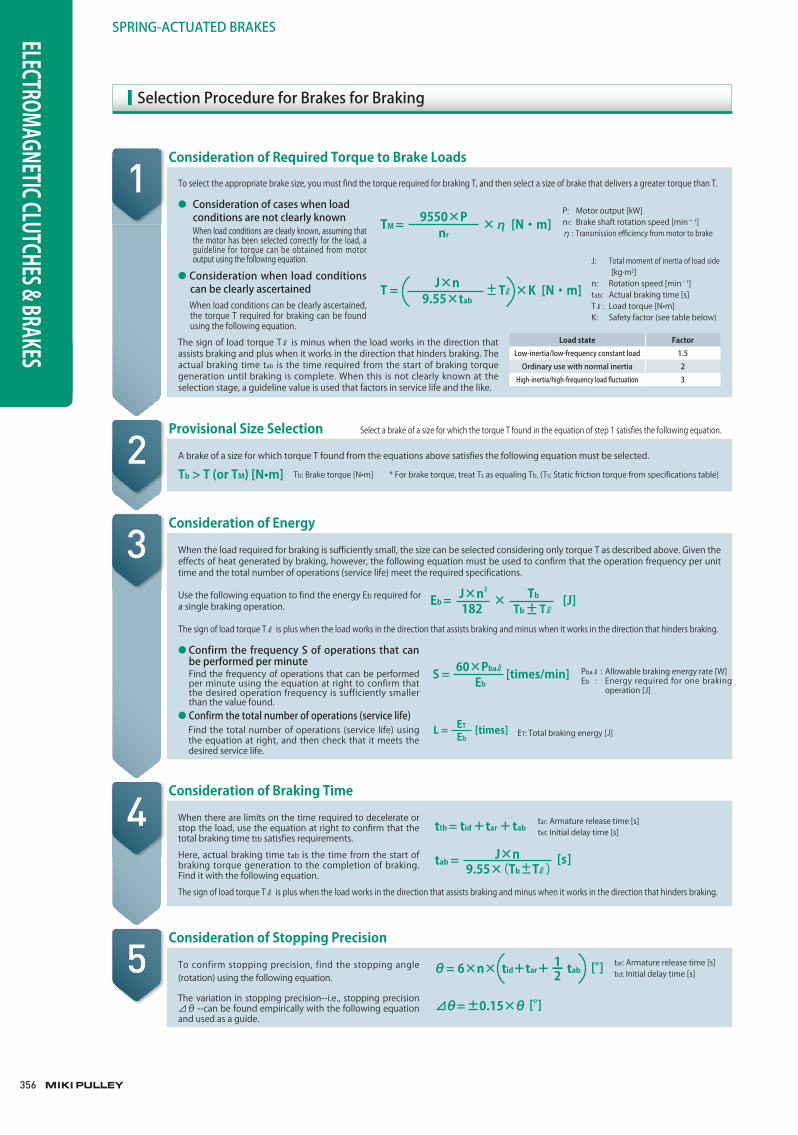
SelectionProcedureforBrakesforBraking
Consideration of Required Torque to Brake Loads
Provisional Size Selection Select a brake of a size for which the torque T found in the equation of step 1 satisfies the following equation.
Consideration of Energy
Consideration of Braking Time
The sign of load torque Tℓ is minus when the load works in the direction that assists braking and plus when it works in the direction that hinders braking. The actual braking time tab is the time required from the start of braking torque generation until braking is complete. When this is not clearly known at the selection stage, a guideline value is used that factors in service life and the like.
Pbaℓ : Allowable braking energy rate [W]Eb : Energy required for one braking
operation [J]
tar: Armature release time [s]tid: Initial delay time [s]
ET: Total braking energy [J]
A brake of a size for which torque T found from the equations above satisfies the following equation must be selected.
Tb > T (or TM) [N•m]
When there are limits on the time required to decelerate or stop the load, use the equation at right to confirm that the total braking time ttb satisfies requirements.
Here, actual braking time tab is the time from the start of braking torque generation to the completion of braking. Find it with the following equation.
The sign of load torque Tℓ is plus when the load works in the direction that assists braking and minus when it works in the direction that hinders braking.
When the load required for braking is sufficiently small, the size can be selected considering only torque T as described above. Given the effects of heat generated by braking, however, the following equation must be used to confirm that the operation frequency per unit time and the total number of operations (service life) meet the required specifications.
Use the following equation to find the energy Eb required for a single braking operation.
The sign of load torque Tℓ is plus when the load works in the direction that assists braking and minus when it works in the direction that hinders braking.
● Confirmthe frequencySofoperations thatcanbeperformedperminute
Find the frequency of operations that can be performed per minute using the equation at right to confirm that the desired operation frequency is sufficiently smaller than the value found.
● Confirmthetotalnumberofoperations(servicelife) Find the total number of operations (service life) using
the equation at right, and then check that it meets the desired service life.
● Considerationofcaseswhenloadconditionsarenotclearlyknown
When load conditions are clearly known, assuming that the motor has been selected correctly for the load, a guideline for torque can be obtained from motor output using the following equation.
● Considerationwhen loadconditionscanbeclearlyascertained
When load conditions can be clearly ascertained, the torque T required for braking can be found using the following equation.
To select the appropriate brake size, you must find the torque required for braking T, and then select a size of brake that delivers a greater torque than T.
P: Motor output [kW]nr: Brake shaft rotation speed [min− 1]η : Transmission efficiency from motor to brake
J: Total moment of inertia of load side [kg·m2]n: Rotation speed [min−1]tab: Actual braking time [s]Tℓ: Load torque [N•m]K: Safety factor (see table below)
TM = × η [N・m]9550×Pnr
T = Tℓ ×K [N・m]J×n +-9.55×tab
S = [times/min]60×Pbaℓ
Eb
ttb= tid+tar+tab
Consideration of Stopping Precisiontar: Armature release time [s]tid: Initial delay time [s]
To confirm stopping precision, find the stopping angle (rotation) using the following equation.
The variation in stopping precision--i.e., stopping precision ⊿θ --can be found empirically with the following equation and used as a guide.
θ= 6×n× tid+tar+ tab [°]1ー2
⊿θ= ±0.15×θ [°]
tab = [ s]9.55×(Tb Tℓ)
J×n+-
L = [times]Eb
ET
Eb = × [J]J×n2
+-182Tb
Tb Tℓ
Load state FactorLow-inertia/low-frequencyconstantload 1.5
Ordinaryusewithnormalinertia 2
High-inertia/high-frequencyloadfluctuation 3
Tb: Brake torque [N•m] * For brake torque, treat Ts as equaling Tb. (Ts: Static friction torque from specifications table)
1
3
4
5
2
356
SPRING-ACTUATEDBRAKESELECTROMAGNETIC CLUTCHES & BRAKES
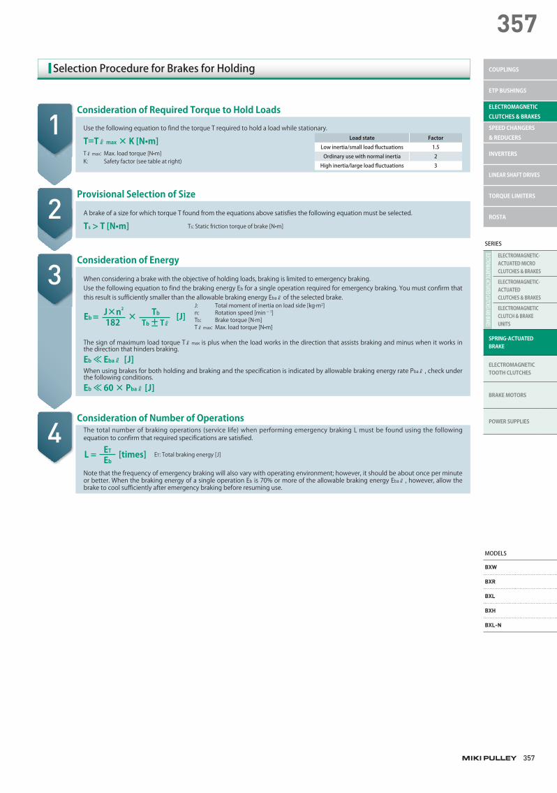
SelectionProcedureforBrakesforHolding
Consideration of Required Torque to Hold Loads
1Load state Factor
Lowinertia/smallloadfluctuations 1.5
Ordinaryusewithnormalinertia 2
Highinertia/largeloadfluctuations 3
Use the following equation to find the torque T required to hold a load while stationary.
T=Tℓ max × K [N•m]Tℓ max: Max. load torque [N•m]K: Safety factor (see table at right)
Consideration of Energy
J: Total moment of inertia on load side [kg·m2]n: Rotation speed [min− 1]Tb: Brake torque [N·m]Tℓ max: Max. load torque [N•m]
When considering a brake with the objective of holding loads, braking is limited to emergency braking.Use the following equation to find the braking energy Eb for a single operation required for emergency braking. You must confirm that this result is sufficiently smaller than the allowable braking energy Ebaℓ of the selected brake.
Eb = × [J]J×n2
+-182Tb
Tb Tℓ
Provisional Selection of Size
A brake of a size for which torque T found from the equations above satisfies the following equation must be selected.
Ts > T [N•m]
The sign of maximum load torque Tℓ max is plus when the load works in the direction that assists braking and minus when it works in the direction that hinders braking.
Eb ≪ Ebaℓ [J]When using brakes for both holding and braking and the specification is indicated by allowable braking energy rate Pbaℓ , check under the following conditions.
Eb ≪ 60 × Pbaℓ [J]
Consideration of Number of OperationsThe total number of braking operations (service life) when performing emergency braking L must be found using the following equation to confirm that required specifications are satisfied.
Note that the frequency of emergency braking will also vary with operating environment; however, it should be about once per minute or better. When the braking energy of a single operation Eb is 70% or more of the allowable braking energy Ebaℓ , however, allow the brake to cool sufficiently after emergency braking before resuming use.
Ts: Static friction torque of brake [N•m]
3
4
2
ET: Total braking energy [J]L = [times]Eb
ET
357
357
SERIES
ELECTROMAGNETIC-ACTUATED CLUTCHES AND BRAKES
ELECTROMAGNETIC-ACTUATED MICRO CLUTCHES & BRAKES
ELECTROMAGNETIC-ACTUATEDCLUTCHES & BRAKES
ELECTROMAGNETIC CLUTCH & BRAKE UNITS
SPRING-ACTUATEDBRAKE
ELECTROMAGNETIC TOOTH CLUTCHES
BRAKE MOTORS
POWER SUPPLIES
MODELS
BXW
BXR
BXL
BXH
BXL-N
COUPLINGS
ETP BUSHINGS
ELECTROMAGNETIC CLUTCHES & BRAKES
SPEED CHANGERS & REDUCERS
INVERTERS
LINEAR SHAFT DRIVES
TORQUE LIMITERS
ROSTA
358
SPRING-ACTUATEDBRAKESELECTROMAGNETIC CLUTCHES & BRAKES
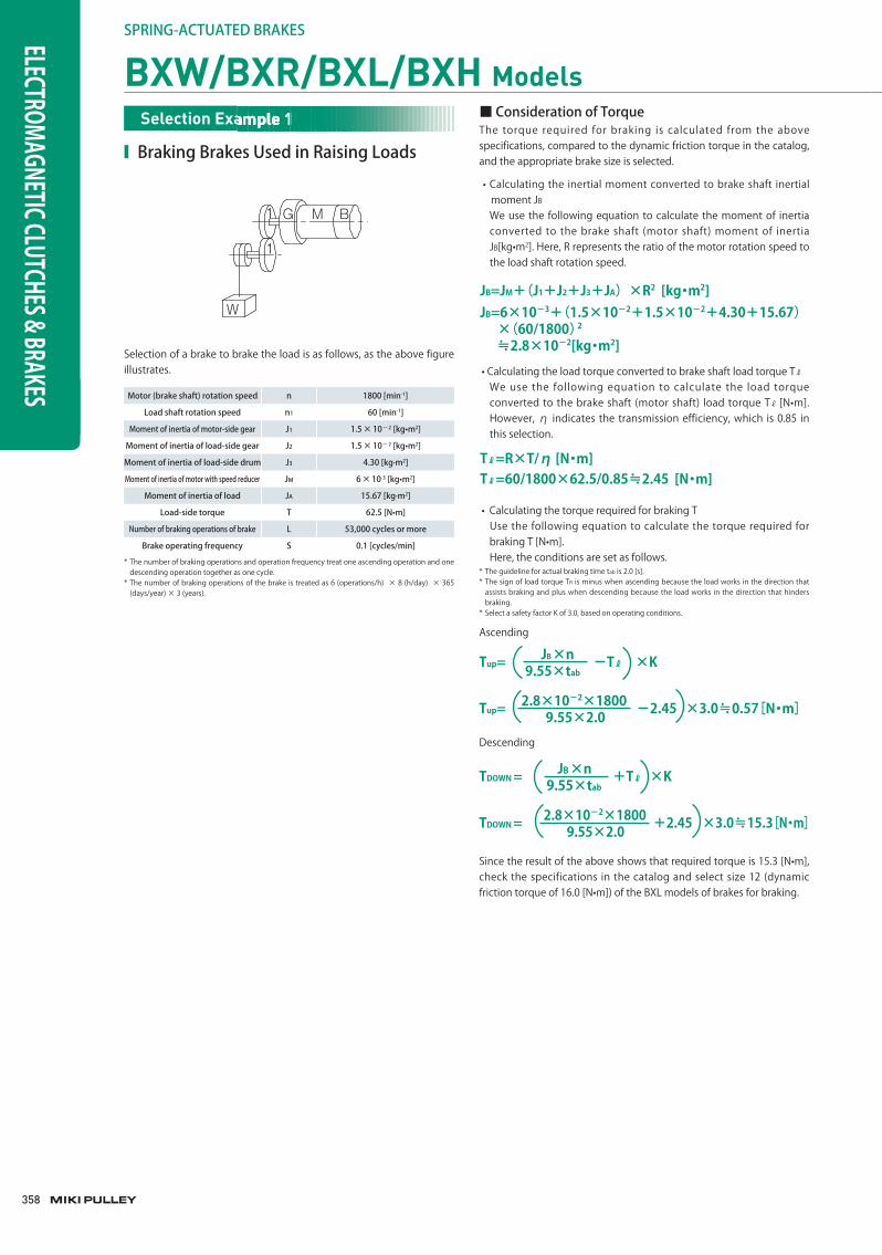
• Calculating the torque required for braking T Use the following equation to calculate the torque required for
braking T [N•m]. Here, the conditions are set as follows.* The guideline for actual braking time tab is 2.0 [s].* The sign of load torque TR is minus when ascending because the load works in the direction that
assists braking and plus when descending because the load works in the direction that hinders braking.
* Select a safety factor K of 3.0, based on operating conditions.
Ascending
Tup= -Tℓ ×K9.55×tab
JB×n
Tup= -2.45 ×3.0≒0.57[N・m]9.55×2.02.8×10-2×1800
Since the result of the above shows that required torque is 15.3 [N•m], check the specifications in the catalog and select size 12 (dynamic friction torque of 16.0 [N•m]) of the BXL models of brakes for braking.
TDOWN = +Tℓ ×K9.55×tab
JB ×n
TDOWN = +2.45 ×3.0≒15.3[N・m]9.55×2.02.8×10-2×1800
Descending
Motor(brakeshaft)rotationspeed n 1800[min-1]
Loadshaftrotationspeed n1 60[min-1]
Momentofinertiaofmotor-sidegear J1 1.5×10⁻²[kg•m2]
Momentofinertiaofload-sidegear J2 1.5×10⁻²[kg•m2]
Momentofinertiaofload-sidedrum J3 4.30[kg·m2]
Momentofinertiaofmotorwithspeedreducer JM 6×10⁻³[kg•m2]
Momentofinertiaofload JA 15.67[kg·m2]
Load-sidetorque T 62.5[N•m]
Numberofbrakingoperationsofbrake L 53,000cyclesormore
Brakeoperatingfrequency S 0.1[cycles/min]
* The number of braking operations and operation frequency treat one ascending operation and one descending operation together as one cycle.
* The number of braking operations of the brake is treated as 6 (operations/h) × 8 (h/day) × 365 (days/year) × 3 (years).
■ConsiderationofTorqueThe torque required for braking is calculated from the above specifications, compared to the dynamic friction torque in the catalog, and the appropriate brake size is selected.
• Calculating the inertial moment converted to brake shaft inertial moment JB
We use the following equation to calculate the moment of inertia converted to the brake shaft (motor shaft) moment of inertia JB[kg•m2]. Here, R represents the ratio of the motor rotation speed to the load shaft rotation speed.
• Calculating the load torque converted to brake shaft load torque Tℓ
We use the following equation to calculate the load torque converted to the brake shaft (motor shaft) load torque Tℓ [N•m]. However, η indicates the transmission efficiency, which is 0.85 in this selection.
JB=JM+(J1+J2+J3+JA)×R2 [kg・m2]JB=6×10⁻³+(1.5×10⁻²+1.5×10⁻²+4.30+15.67) ×(60/1800)2
≒2.8×10⁻²[kg・m2]
Tℓ=R×T/η [N・m]Tℓ=60/1800×62.5/0.85≒2.45 [N・m]
G M B
W
1
1
■ BrakingBrakesUsedinRaisingLoads
BXW/BXR/BXL/BXH ModelsSelection Example 1Selection Example 1Selection Example 1
Selection of a brake to brake the load is as follows, as the above figure illustrates.
359
359
SERIES
ELECTROMAGNETIC-ACTUATED CLUTCHES AND BRAKES
ELECTROMAGNETIC-ACTUATED MICRO CLUTCHES & BRAKES
ELECTROMAGNETIC-ACTUATEDCLUTCHES & BRAKES
ELECTROMAGNETIC CLUTCH & BRAKE UNITS
SPRING-ACTUATEDBRAKE
ELECTROMAGNETIC TOOTH CLUTCHES
BRAKE MOTORS
POWER SUPPLIES
MODELS
BXW
BXR
BXL
BXH
BXL-N
COUPLINGS
ETP BUSHINGS
ELECTROMAGNETIC CLUTCHES & BRAKES
SPEED CHANGERS & REDUCERS
INVERTERS
LINEAR SHAFT DRIVES
TORQUE LIMITERS
ROSTA
• Calculating the amount of energy required for one braking operation Eb
The calculated total moment of inertia is used to calculate the energy required by a single braking operation. Here, the sign of load torque Tℓ is plus when ascending because the load works in the direction that assists braking and minus when descending because the load works in the direction that hinders braking.
Ascending
• Confirm the frequency S of operations that can be performed per minute
Substitute the energy required for a single braking Eb calculated above and the allowable braking energy rate Pbaℓ for the BXL-12 (catalog value 133.3 W) into the following equation and calculate the frequency S of operations that can be performed per minute.
Ascending
■ConsiderationofEnergyConfirm that the brake selected based on required torque satisfies the required specifications for number of braking operations and braking frequency.
• Calculating the total moment of inertia J Adding the inertial moment converted to brake shaft inertial
moment JB that was just calculated to the inertial moment of the rotating parts of the provisionally selected BXL-12 (catalog value of 33.75 × 10− 5), we arrive at the total moment of inertia.
J = 2. 8×10⁻² +33.75×10⁻⁵
≒2.83×10⁻²[kg・m2 ]
Ebup= ×182J×n2
Tb+Tℓ
Tb
Ebup= ×
≒437[J]182
2.83×10-2×18002
16.0+2.4516.0
EbDOWN= ×182J×n2
Tb-Tℓ
Tb
EbDOWN= ×
≒595[J]182
2.83×10-2×18002
16.0-2.4516.0
Sup= Ebup
60×Pbaℓ
Sup=
≒ 18.3 [times/min.]437
60×133.3
SDOWN= EbDOWN
60×Pbaℓ
SDOWN=
≒ 13.4 [times/min.]595
60×133.3
Descending
Descending
The desired operation frequency is sufficiently smaller than the calculated operation frequency, so the specification is satisfied. Note that the braking energy rate (catalog value) used in the calculation is the value under ideal conditions, so the desired operation frequency needs to be sufficiently small.
13.4 [times/min.] ≫ 0.1 [times/min.]
• Calculating the total number of operations (service life) Substituting in the just-calculated energy required for a single
braking Eb and the BXL-12 total frictional energy ET (catalog value of 9.0 × 10⁷ [J]), we arrive at the total number of operations L.
If the energy of a single cycle of ascending and descending Eb is:
Eb=Ebup+EbDOWN
Eb=1032[J]
L= Eb
ET
L=
≒ 87209 [cycles]1032
9.0×10⁷
tab =9.55×(Tb-Tℓ)
J×n
tab =
9.55×(16.0-2.45)2.83×10-2×1800
≒0.39[s]
ttb=0.025+0.030+0.39 ≒0.445[s]
θ=6×n×(tid+tar+1/2×tab) =2700[゜]
⊿θ= 0.15×θ = 405[゜]
+-+-
Bd=θmax/360×R×π×Dd
=(3105/360)×(60/1800)×π×0.5 =0.45[m]
The total number of operations L is:
The desired total number of operations is fewer than the calculated total number of operations (service life), so the specification is satisfied.
Here, the armature release time tar of the BXL-12 from the catalog is 0.03 [s]. The initial delay time tid is the delay of the operation of relays and the like, so we use 0.025 [s], the typical relay operation time. Thus, the total braking time ttb is:
The variation in stopping precision--i.e., stopping precision ⊿θ --can be found empirically with the following equation and used as a guide.
This angle is the angle at the brake shaft, so when the stopping precision θ max is 2700 + 405 = 3105 [°] and the drum diameter Dd is 0.5 [m], the braking distance Bd of load W is:
If there is no problem with the braking time and stopping precision, BXL-12 can be selected.
87,209 [cycles] > 53,000 [cycles]
■ConsiderationofBrakingTimeTotal braking time ttb is calculated as the sum of actual braking time tab, armature release time tar, and the initial delay time from start of command input to start of operating input tid.Here, the actual braking time is expected to be greater in the descending direction, so only the case of descending is considered. The sign of the load torque Tℓ is minus, since it is in the direction that impedes braking.
■ConsiderationofStoppingPrecisionWhen stopping precision (stopping distance) is restricted, calculate stopping precision using the following equations.
360
SPRING-ACTUATEDBRAKESELECTROMAGNETIC CLUTCHES & BRAKES
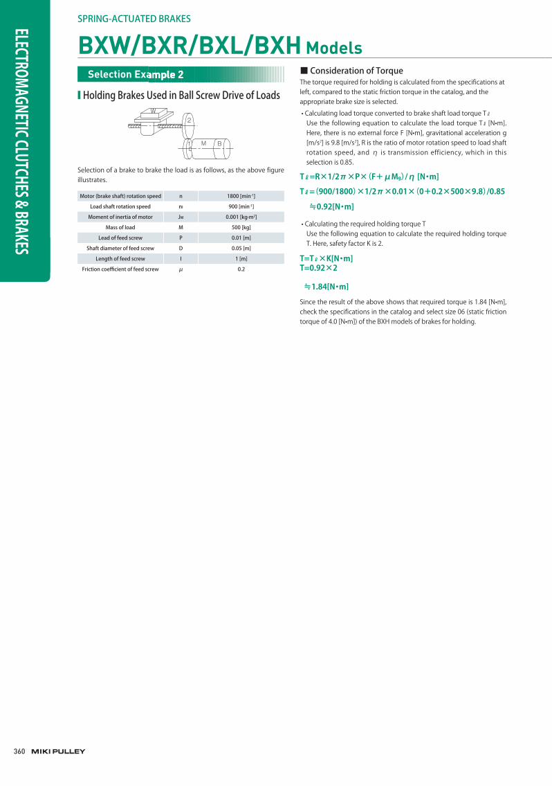
■ HoldingBrakesUsedinBallScrewDriveofLoads
Selection of a brake to brake the load is as follows, as the above figure illustrates.
Motor(brakeshaft)rotationspeed n 1800[min-1]
Loadshaftrotationspeed nl 900[min-1]
Momentofinertiaofmotor JM 0.001[kg·m2]
Massofload M 500[kg]
Leadoffeedscrew P 0.01[m]
Shaftdiameteroffeedscrew D 0.05[m]
Lengthoffeedscrew I 1[m]
Frictioncoefficientoffeedscrew μ 0.2
M B
W2
1
■ConsiderationofTorqueThe torque required for holding is calculated from the specifications at left, compared to the static friction torque in the catalog, and the appropriate brake size is selected.
• Calculating load torque converted to brake shaft load torque Tℓ
Use the following equation to calculate the load torque Tℓ [N•m]. Here, there is no external force F [N•m], gravitational acceleration g [m/s2] is 9.8 [m/s2], R is the ratio of motor rotation speed to load shaft rotation speed, and η is transmission efficiency, which in this selection is 0.85.
Since the result of the above shows that required torque is 1.84 [N•m], check the specifications in the catalog and select size 06 (static friction torque of 4.0 [N•m]) of the BXH models of brakes for holding.
• Calculating the required holding torque T Use the following equation to calculate the required holding torque
T. Here, safety factor K is 2.
T=Tℓ×K[N・m]T=0.92×2
≒1.84[N・m]
Tℓ=R×1/2π×P×(F+μMg)/η [N・m]
Tℓ=(900/1800)×1/2π×0.01×(0+0.2×500×9.8)/0.85
≒0.92[N・m]
BXW/BXR/BXL/BXH ModelsSelection Example 2Selection Example 2Selection Example 2
361
361
SERIES
ELECTROMAGNETIC-ACTUATED CLUTCHES AND BRAKES
ELECTROMAGNETIC-ACTUATED MICRO CLUTCHES & BRAKES
ELECTROMAGNETIC-ACTUATEDCLUTCHES & BRAKES
ELECTROMAGNETIC CLUTCH & BRAKE UNITS
SPRING-ACTUATEDBRAKE
ELECTROMAGNETIC TOOTH CLUTCHES
BRAKE MOTORS
POWER SUPPLIES
MODELS
BXW
BXR
BXL
BXH
BXL-N
COUPLINGS
ETP BUSHINGS
ELECTROMAGNETIC CLUTCHES & BRAKES
SPEED CHANGERS & REDUCERS
INVERTERS
LINEAR SHAFT DRIVES
TORQUE LIMITERS
ROSTA
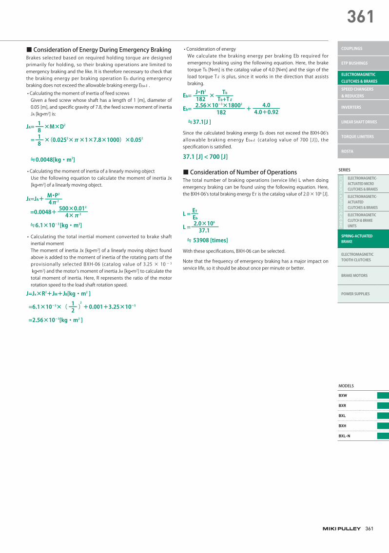
■ConsiderationofNumberofOperationsThe total number of braking operations (service life) L when doing emergency braking can be found using the following equation. Here, the BXH-06's total braking energy ET is the catalog value of 2.0 × 10⁶ [J].
■ConsiderationofEnergyDuringEmergencyBrakingBrakes selected based on required holding torque are designed primarily for holding, so their braking operations are limited to emergency braking and the like. It is therefore necessary to check that the braking energy per braking operation Eb during emergency braking does not exceed the allowable braking energy Ebaℓ .
• Calculating the moment of inertia of feed screws Given a feed screw whose shaft has a length of 1 [m], diameter of
0.05 [m], and specific gravity of 7.8, the feed screw moment of inertia JA [kg•m2] is:
• Calculating the moment of inertia of a linearly moving object Use the following equation to calculate the moment of inertia Jx
[kg•m2] of a linearly moving object.
• Calculating the total inertial moment converted to brake shaft inertial moment
The moment of inertia Jx [kg•m2] of a linearly moving object found above is added to the moment of inertia of the rotating parts of the provisionally selected BXH-06 (catalog value of 3.25 × 10 − 5
kg•m2) and the motor's moment of inertia JM [kg•m2] to calculate the total moment of inertia. Here, R represents the ratio of the motor rotation speed to the load shaft rotation speed.
JA= ×M×D2
= ×(0.0252×π×1×7.8×1000)×0.052
≒0.0048[kg・m2]
1ー81ー8
JX=JA+
=0.0048+
≒6.1×10⁻³ [kg・m2]
4π2M・P2
4×π2500×0.012
J=Jx×R2+JM+JB[kg・m2 ]
=6.1×10⁻³×( )2
+0.001+3.25×10-5
=2.56×10⁻³[kg・m2 ]
1ー2
• Consideration of energy We calculate the braking energy per braking Eb required for
emergency braking using the following equation. Here, the brake torque Tb [N•m] is the catalog value of 4.0 [N•m] and the sign of the load torque Tℓ is plus, since it works in the direction that assists braking.
37.1 [J] < 700 [J]
Eb= ×
Eb= +
≒37.1[J ]
182J・n2
1822.56×10-3×18002
Tb+Tℓ
Tb
4.0+0.924.0
L =
L =
≒ 53908 [times]
Eb
ET
37.12.0×106
Since the calculated braking energy Eb does not exceed the BXH-06's allowable braking energy Ebaℓ (catalog value of 700 [ J]), the specification is satisfied.
With these specifications, BXH-06 can be selected.
Note that the frequency of emergency braking has a major impact on service life, so it should be about once per minute or better.
362
SPRING-ACTUATEDBRAKESELECTROMAGNETIC CLUTCHES & BRAKES
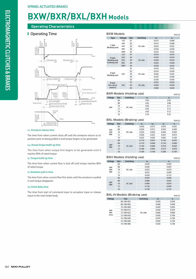
■ OperatingTime BXW ModelsType Voltage Size Switching tar ta
L type(Braking use)
12V 01
DCside
0.015 0.00824V 02 0.015 0.00845V 03 0.025 0.02590V 04 0.030 0.030180V 05 0.035 0.035
H type(Holding and braking use)
12V 01
DCside
0.010 0.01024V 02 0.010 0.01045V 03 0.020 0.03590V 04 0.025 0.040180V 05 0.030 0.045
S type(Holding use) 24V
01
DCside
0.010 0.02502 0.010 0.03003 0.020 0.03504 0.025 0.04005 0.030 0.045
R type(For servo
motors)24V
01DCside
0.035 0.02003 0.050 0.02005 0.060 0.020
Unit[s]
BXL Models (Braking use)Voltage Size Switching tar tap tp ta
24V45V90V
06
DCside
0.020 0.015 0.035 0.03508 0.020 0.015 0.035 0.04010 0.025 0.020 0.045 0.05012 0.030 0.025 0.055 0.07016 0.035 0.030 0.065 0.100
45V90V
06
ACside
0.110 0.035 0.145 0.03508 0.110 0.040 0.150 0.04010 0.150 0.060 0.210 0.05012 0.180 0.095 0.275 0.07016 0.180 0.100 0.280 0.100
Unit[s]
BXL-N Models (Braking use)Voltage Size Switching tar ta
24V99V
171V
08-10N-002
DCside
0.050 0.03008-10N-004 0.040 0.04010-10N-008 0.050 0.05010-10N-015 0.030 0.07012-10N-022 0.060 0.08012-10N-030 0.030 0.10016-10N-040 0.070 0.10016-10N-060 0.050 0.10016-10N-080 0.030 0.100
Unit[s]
BXH Models (Holding use)Voltage Size Switching tar ta
24V45V90V
06
DCside
0.020 0.04008 0.020 0.04510 0.025 0.07012 0.025 0.09016 0.030 0.125
45V90V
06
ACside
0.070 0.04008 0.080 0.04510 0.090 0.07012 0.120 0.09016 0.140 0.125
Unit[s]
Actual torque build-up time (tap)Torque build-up time (tp)
Release time (tre)Torque decaying time (td)
Drag torque
Damping torque
10% of rated torque (Tr)
Braking time (tb)Total braking time (ttb)
Stop
Driven side
Time
Time
Time
Time
Actual braking time (tab)
Armature pull-in time(ta)
(Ts)(Td)
Rot
atio
n s
peed
Torq
ueEx
cita
tion
curr
ent
Exci
tatio
n vo
ltage
Con
trol
in
put
Ope
ratin
g in
put
Con
trol
in
put
Ope
ratin
g in
put
Initial delay time(tid)
Initial delay time(tid)
Armature release time(tar)
80% of rated dynamic torque (Ti)
Static frictiontorque
Dynamicfrictiontorque
tar:Armaturereleasetime
ta:Armaturepull-intime
tid:Initialdelaytime
tp:Torquebuild-uptime
tap:Actualtorquebuild-uptime
The time from when current shuts off until the armature returns to its position prior to being pulled in and torque begins to be generated
The time from when current flow first starts until the armature is pulled in and torque disappears
The time from start of command input to actuation input or release input to the main brake body
The time from when current flow is shut off until torque reaches 80% of rated torque
The time from when torque first begins to be generated until it reaches 80% of rated torque
BXW/BXR/BXL/BXH ModelsOperating Characteristics
BXR Models (Holding use)Voltage Size Switching tar ta
24V
06
DCside
0.02 0.0508 0.02 0.0810 0.05 0.1112 0.03 0.1214 0.03 0.1216 0.10 0.22
Unit[s]
363
363
SERIES
ELECTROMAGNETIC-ACTUATED CLUTCHES AND BRAKES
ELECTROMAGNETIC-ACTUATED MICRO CLUTCHES & BRAKES
ELECTROMAGNETIC-ACTUATEDCLUTCHES & BRAKES
ELECTROMAGNETIC CLUTCH & BRAKE UNITS
SPRING-ACTUATEDBRAKE
ELECTROMAGNETIC TOOTH CLUTCHES
BRAKE MOTORS
POWER SUPPLIES
MODELS
BXW
BXR
BXL
BXH
BXL-N
COUPLINGS
ETP BUSHINGS
ELECTROMAGNETIC CLUTCHES & BRAKES
SPEED CHANGERS & REDUCERS
INVERTERS
LINEAR SHAFT DRIVES
TORQUE LIMITERS
ROSTA
■ 45V,90V,and96VSpecificationsforBXW,BXR,BXL,andBXHModels(Single-phaseHalf-waveRectified)
■AC-sideSwitchingThis is the usual switching method. Connection is simple.
■DC-sideSwitchingThis method achieves even faster operational characteristics than AC-side switching.
Switch Diode
Brake
Circ
uit p
rote
ctor
Dio
de
100 V ACor
200 V AC
SwitchDiode
Brake
Circ
uit p
rote
ctor
Circ
uit p
rote
ctor
Dio
de
100 V ACor
200 V AC
■ 12Vand24VSpecificationsforBXW,BXR,BXL,andBXHModels(Single-phaseFull-waveRectified)
■ 90V,96V,180V,and190VSpecificationsforBXWModels(Single-phaseFull-waveRectified)
Brake size Pre-rectification voltage[V] Recommended varistor model
01 ~ 18
AC30orbelow NVD07SCD082oranequivalent
OverAC30toAC110orbelow NVD07SCD220oranequivalent
OverAC110toAC220orbelow NVD07SCD470oranequivalent
OverAC220toAC460orbelow NVD14SCD820oranequivalent
20 ~ 25
AC30orbelow NVD14SCD082oranequivalent
OverAC30toAC110orbelow NVD14SCD220oranequivalent
OverAC110toAC220orbelow NVD14SCD470oranequivalent
OverAC220toAC460orbelow NVD14SCD820oranequivalent
* NVD □ SCD □ parts are manufactured by KOA Corporation.
■CircuitProtectorsIf using a power supply that is not equipped with a circuit protector for DC switching, make sure to connect the recommended circuit protector device in parallel with the brake. However, with some circuit protectors, operation times may lengthen. In such cases, we recommend use of varistors.Select varistors from the following table based on brake size and AC voltage before rectification.Note that the 24 V specifications of BXL and BXH as well as all BXR models are supplied with varistors. See Included varistors for each model.
■DC-sideSwitching ■DC-sideSwitching
Brake
Switch
Rec
tifier
Circ
uit p
rote
ctor
Circ
uit p
rote
ctor
Tran
sfor
mer
ACBrake
Switch
Circ
uit p
rote
ctor
Circ
uit p
rote
ctor
Rec
tifier100 V AC
or200 V AC
Control Circuits


![ELECTROMAGNETIC-ACTUATED CLUTCHES AND ......ELECTROMAGNETIC-ACTUATED CLUTCHES AND BRAKES Product Lineup P.300 P.304 P.306 P.308 CBW CMW 121- -10G122 Clutch/brake torque [N·m] 5 〜](https://img.pdfslide.net/doc/110x75/5ffb1037c8e50875111bc0eb/electromagnetic-actuated-clutches-and-electromagnetic-actuated-clutches.jpg)