Embed Size (px)
Citation preview

SPRINGHOUSE SHINGLES™ INSTALLATION MANUAL
SPRINGHOUSE SHINGLES™PRODUCT & INSTALLATION GUIDE
SPRINGHOUSE SHINGLES™ INSTALLATION MANUAL
TAbLE Of CONTENTS
General Overview
Installation Overview
Installation A. Perimeter or Drip Edge Flashing
B. Valley
C. Flashing at Vertical Walls
D. Shingles
E. Hip and Ridge
F. Chimney Flashings
G. Additional Flashing
Snow Control
SPRINGHOUSE SHINGLES™ INSTALLATION MANUAL
AN OvERvIEw Of SPRINGHOUSE SHINGLES™
METAL ROOfING IS SLIPPERy wHEN wET, DUSTy OR fROSTy. wHEN THESE CONDITIONS ExIST STAy Off THE ROOf. USE REqUIRED SAfETy PROCEDURES wHEN INSTALLING ALL ROOfING MATERIALS.
SPRINGHOUSE SHINGLES MUST bE APPLIED PROPERLy. PROPERLy PREPARE THE SURfACE TO bE ROOfED. PROvIDE PROPER vENTILATION IN ACCORDANCE wITH MINIMUM PROPERTy STANDARDS REqUIREMENTS.
DISCLAIMER Of LIAbILITyAndex Metals Division of Agway Metals Inc. assumes no responsibility for leaks or defects resulting from the improper installation of Springhouse Shingles™ and any related accessories, flashings, nor for any personal or property injury (special, indirect or consequential damages) that may occur with the products use.
The instructions contain suggested application procedures; it is the responsibility of the designer and the installer to ensure conformity to local buildings codes and provide adequate weather tightness. Review all applicable building codes, minimum property standards and requirements prior to applying these shingles. If necessary, consult a local architect / engineer for requirements of local codes and conditions. Even though Springhouse Shingles™ is relatively easy to install, before beginning, you should thoroughly read the instruction booklet to understand how they apply to your roofing project.
For more specific information concerning your projects, please contact us directly on our technical service line. We will gladly provide you with any additional information you may need.
Springhouse Shingles™, like all roofing materials should be carefully installed. Mistakes in installation can cause roof problems later on. So take your time and closely follow the installation guidelines.
GENERAL CONSIDERATIONS • Installation of Springhouse Shingles™ is recommended on a 3/12 or steeper pitch. Do not use pressure treated lumber in direct
contact with Springhouse Shingles.
• All surfaces on which the work is to be applied shall be examined for flatness as appropriate to application. All surfaces must be covered with an appropriate underlayment, whether a new or a retrofit installation. When installing over an existing asphalt roof, make sure all damaged or curled shingles are corrected. It is recommended that the removal of existing asphalt shingles prior to installing Springhouse shingles will give the best results for the job.
• Shingles shall be installed so that horizontal lines are level and vertical lines are even.
• All sheet metal work shall conform to standards set forth in the SMACNA Architectural sheet metal manual and the Steep Roofing Manual published by the National Roofing Contractors Association.
• Fasteners shall be concealed as provided by manufacturer.
• Wear soft sole shoes when walking on Springhouse Shingles™ to prevent slipping and avoid damage to the painted surfaces. If scratches do occur, then use the appropriate touch up paint supplied by Andex /Agway.
• Use only accessories designed for this product. Do not use dissimilar materials. Insulate roofing and flashings from contact with dissimilar metals where necessary.
• Metal filings from cutting, drilling or fastening can begin to rust even from overnight dew. This could stain or abrade finished surfaces.
NOTE: The primary purpose of a roof is to protect the building from the elements. The installation of all roofing materials must be constructed to shed rain and snow away from the building and prevent water from penetrating the roof space. Most steep-slope roofing materials are designed for use as water shedding systems. Steep-slope water shedding roof systems are not impermeable, and they rely on slope to shed water off the roof surface.
01
SPRINGHOUSE SHINGLES™ INSTALLATION MANUAL
AN OvERvIEw Of SPRINGHOUSE SHINGLES™INSTALLATION GUIDELINESThe following installation guidelines and those outlined in the Andex Metals Division of Agway Metals Inc. installation booklet for Springhouse Shingles™ are suggested methods for installing Springhouse Shingles™ and are proven construction methods. The installer must be familiar with all installation instructions before starting work.
Before beginning installation, the installer must examine the substrate to ensure that all supporting members are straight, level, plumb, and true in accordance with minimum tolerances. Report any potential problems to the general contractor or the home owner. Please do not start work until unsatisfactory conditions have been corrected. The installer may utilize details provided and procedures recommended for installation of Springhouse Shingles™. However, the details may require adaptations, changes, or revisions for your particular project since conditions vary and may be unique. It is the responsibility of the designer and installer to ensure that the details are adapted and applied to meet the particular building requirements and to provide adequate weather tightness.
Andex Metals Division of Agway Metals Inc. shall be held harmless from any and all claims arising from a lack of weather tightness as a result of following these suggested typical detailed drawings. Some field cutting and fitting of shingles and flashings is expected of the installer and minor field corrections of materials are a part of normal installation work. Workmanship will be by the best industry standards, and installation shall be performed by roofers with experience in metal roofing. SMACNA (Sheet Metal and Air Conditioning Contractors National Association) Architectural Sheet Metal manual specifications shall govern for material and workmanship not shown.
TOOLS REqUIRED STORAGERubber Mallet Install the metal shingles as soon as possible or store in a cool, dry,Tin Snips well ventilated area prior to installation. If storage is unavoidable, be Hammer or Nail Gun sure to store away from any chemical substances.Screw Gun for Screw fastenersMeasuring TapeBar FolderRoof JacksTie Downs
SHIPPINGAGWAY Metals Inc. will deliver to a contractor’s shop or the ob-site address (within our normal delivery routes) with a 1 week notice period.
HELP LINEFor specific information concerning your project, contact AGWAY Metals Inc.:Exeter, Ontario - 519.235.2901 or 1.800.265.7070 orBrampton, Ontario - 905.799.7535 or 1.800.268.2083
02
SPRINGHOUSE SHINGLES™ INSTALLATION MANUAL
INSTALLATION OvERvIEw
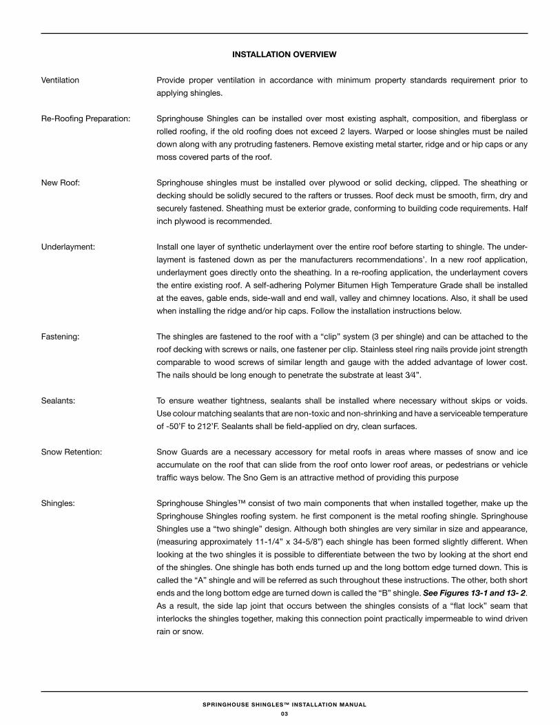
Ventilation Provide proper ventilation in accordance with minimum property standards requirement prior to applying shingles.
Re-Roofing Preparation: Springhouse Shingles can be installed over most existing asphalt, composition, and fiberglass or rolled roofing, if the old roofing does not exceed 2 layers. Warped or loose shingles must be nailed down along with any protruding fasteners. Remove existing metal starter, ridge and or hip caps or any moss covered parts of the roof.
New Roof: Springhouse shingles must be installed over plywood or solid decking, clipped. The sheathing or decking should be solidly secured to the rafters or trusses. Roof deck must be smooth, firm, dry and securely fastened. Sheathing must be exterior grade, conforming to building code requirements. Half inch plywood is recommended.
Underlayment: Install one layer of synthetic underlayment over the entire roof before starting to shingle. The under-layment is fastened down as per the manufacturers recommendations’. In a new roof application, underlayment goes directly onto the sheathing. In a re-roofing application, the underlayment covers the entire existing roof. A self-adhering Polymer Bitumen High Temperature Grade shall be installed at the eaves, gable ends, side-wall and end wall, valley and chimney locations. Also, it shall be used when installing the ridge and/or hip caps. Follow the installation instructions below.
Fastening: The shingles are fastened to the roof with a “clip” system (3 per shingle) and can be attached to the roof decking with screws or nails, one fastener per clip. Stainless steel ring nails provide joint strength comparable to wood screws of similar length and gauge with the added advantage of lower cost. The nails should be long enough to penetrate the substrate at least 3⁄4”.
Sealants: To ensure weather tightness, sealants shall be installed where necessary without skips or voids. Use colour matching sealants that are non-toxic and non-shrinking and have a serviceable temperature of -50’F to 212’F. Sealants shall be field-applied on dry, clean surfaces.
Snow Retention: Snow Guards are a necessary accessory for metal roofs in areas where masses of snow and ice accumulate on the roof that can slide from the roof onto lower roof areas, or pedestrians or vehicle traffic ways below. The Sno Gem is an attractive method of providing this purpose
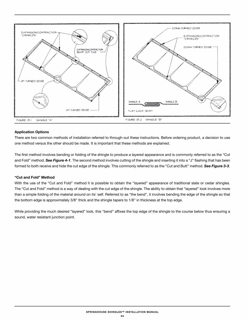
Shingles: Springhouse Shingles™ consist of two main components that when installed together, make up the Springhouse Shingles roofing system. he first component is the metal roofing shingle. Springhouse Shingles use a “two shingle” design. Although both shingles are very similar in size and appearance, (measuring approximately 11-1/4” x 34-5/8”) each shingle has been formed slightly different. When looking at the two shingles it is possible to differentiate between the two by looking at the short end of the shingles. One shingle has both ends turned up and the long bottom edge turned down. This is called the “A” shingle and will be referred as such throughout these instructions. The other, both short ends and the long bottom edge are turned down is called the “B” shingle. See Figures 13-1 and 13- 2. As a result, the side lap joint that occurs between the shingles consists of a “flat lock” seam that interlocks the shingles together, making this connection point practically impermeable to wind driven rain or snow.
03
SPRINGHOUSE SHINGLES™ INSTALLATION MANUAL
Application OptionsThere are two common methods of installation referred to through-out these instructions. Before ordering product, a decision to use one method versus the other should be made. It is important that these methods are explained.
The first method involves bending or folding of the shingle to produce a layered appearance and is commonly referred to as the “Cut and Fold” method. See Figure 4-1. The second method involves cutting of the shingle and inserting it into a “J” flashing that has been formed to both receive and hide the cut edge of the shingle. This commonly referred to as the “Cut and Butt” method. See Figure 3-3.
“Cut and fold” MethodWith the use of the “Cut and Fold” method it is possible to obtain the “layered” appearance of traditional slate or cedar shingles. The “Cut and Fold” method is a way of dealing with the cut edge of the shingle. The ability to obtain that “layered” look involves more than a simple folding of the material around on its’ self. Referred to as “the bend”, it involves bending the edge of the shingle so that the bottom edge is approximately 3/8” thick and the shingle tapers to 1/8” in thickness at the top edge.
While providing the much desired “layered” look, this “bend” affixes the top edge of the shingle to the course below thus ensuring a sound, water resistant junction point.
04
SPRINGHOUSE SHINGLES™ INSTALLATION MANUAL
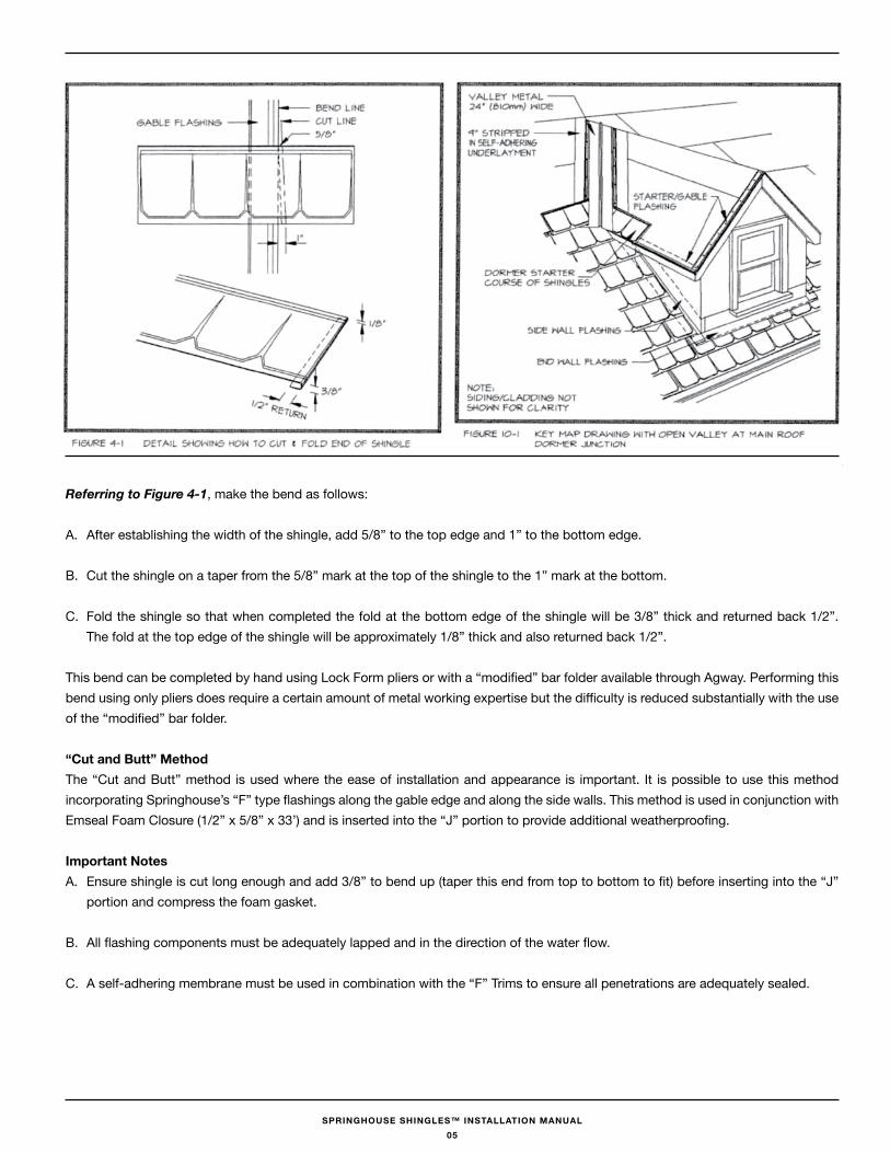
Referring to Figure 4-1, make the bend as follows:
A. After establishing the width of the shingle, add 5/8” to the top edge and 1” to the bottom edge.
B. Cut the shingle on a taper from the 5/8” mark at the top of the shingle to the 1” mark at the bottom.
C. Fold the shingle so that when completed the fold at the bottom edge of the shingle will be 3/8” thick and returned back 1/2”. The fold at the top edge of the shingle will be approximately 1/8” thick and also returned back 1/2”.
This bend can be completed by hand using Lock Form pliers or with a “modified” bar folder available through Agway. Performing this bend using only pliers does require a certain amount of metal working expertise but the difficulty is reduced substantially with the use of the “modified” bar folder.
“Cut and butt” MethodThe “Cut and Butt” method is used where the ease of installation and appearance is important. It is possible to use this method incorporating Springhouse’s “F” type flashings along the gable edge and along the side walls. This method is used in conjunction with Emseal Foam Closure (1/2” x 5/8” x 33’) and is inserted into the “J” portion to provide additional weatherproofing.
Important NotesA. Ensure shingle is cut long enough and add 3/8” to bend up (taper this end from top to bottom to fit) before inserting into the “J”
portion and compress the foam gasket.
B. All flashing components must be adequately lapped and in the direction of the water flow.
C. A self-adhering membrane must be used in combination with the “F” Trims to ensure all penetrations are adequately sealed.
05
SPRINGHOUSE SHINGLES™ INSTALLATION MANUAL
fastener RequirementsSpringhouse Shingles should be attached to the roof decking with stainless steel ring nails. Ring nails provide joint strength compa-rable to wood screws of similar length and gauge with the added advantage of lower cost. The annular ring “barbs” force wood fibers apart as the nail is driven; wood’s natural resilience causes the wood fibers to spring back filling the grooves between the rings and creating a “locking” effect. Nails thus locked in place resist pull-out stresses even when wood swells or shrinks.
A. Using provided stainless steel ring roofing nails ensures completion of the Springhouse Shingle roof system.
B. Stainless roofing nails are made of 11 gauge wire, and the heads should be 3/8” (10 mm) in diameter.
C. Nails should be long enough to penetrate through all layers of underlayments and should extend through the underside of plywood or other acceptable wood panel decks, and penetrate at least 3/4” (19 mm) into wood plank decks.
D. Screw fasteners for the ridge/hip caps should be zinc plated carbon #8 x 1.5” Pan Head Fastener.
E. The fastening of hips, ridges and some on-roof accessories (e.g., shingle-over ridge vents) may require the use of longer fasteners, as the fasteners generally must penetrate through more layers before it can penetrate the roof deck.
F. Re-roofing (the application of Springhouse Shingles over existing asphalt roofing materials) is not considered best practice but in conjunction with underlayments to separate the asphalt shingles from the Springhouse Shingle is considered to be acceptable.
G. Ensure that no nail penetrates the actual side lap joint that occurs between two shingles.
H. Use a minimum of 3 clips per shingle and one fastener per clip.
I. Do not over drive fasteners.
flashingsBecause steep-slope roofs are frequently interrupted by the intersection of adjoining roof sections (valleys), adjacent walls (side walls), or penetrations such as chimneys and plumbing soil-pipe stacks, all of which create opportunities for leakage, special provisions for weather protection must be made at these locations. The components used to control water entry at these locations are commonly called flashings. Careful attention to flashing details is essential to successful long-term roof performance, regardless of the type of roof construction.
Perimeter or “Drip-Edge” flashing
Springhouse Shingles shall be anchored along all roof perimeters with the use of a preformed drip edge.
Perimeter or “drip-edge” metal flashings are an integral part of the Springhouse Shingle system. While securing the perimeter edge of the shingles, the flashings allow water to drip off the edge of the roof without affecting the underlying construction. This metal “drip edge” component is applied along the eave as the #21 Eave Starter and #30 Gable F Trim along the sloped edge of the gable (rake) area. The #21 Eave Starter should be installed below the underlayment at the down slope edges to help prevent any water shed by the underlayment from becoming trapped below the metal at the down slope edge. They should be installed on top of the underlayment at the gable with #30 Gable F Trim. If there is concern that trapped ice or snow in a gutter at the down slope edge will back up under the metal edge then an additional strip of underlayment should be installed first under the metal at the down slope edge. (Note: installation of the metal drip edge over a narrow width a self-adhering modified bitumen membrane High Temperature to separate the metal from direct contact with the roof deck, is recommended.)
06
SPRINGHOUSE SHINGLES™ INSTALLATION MANUAL
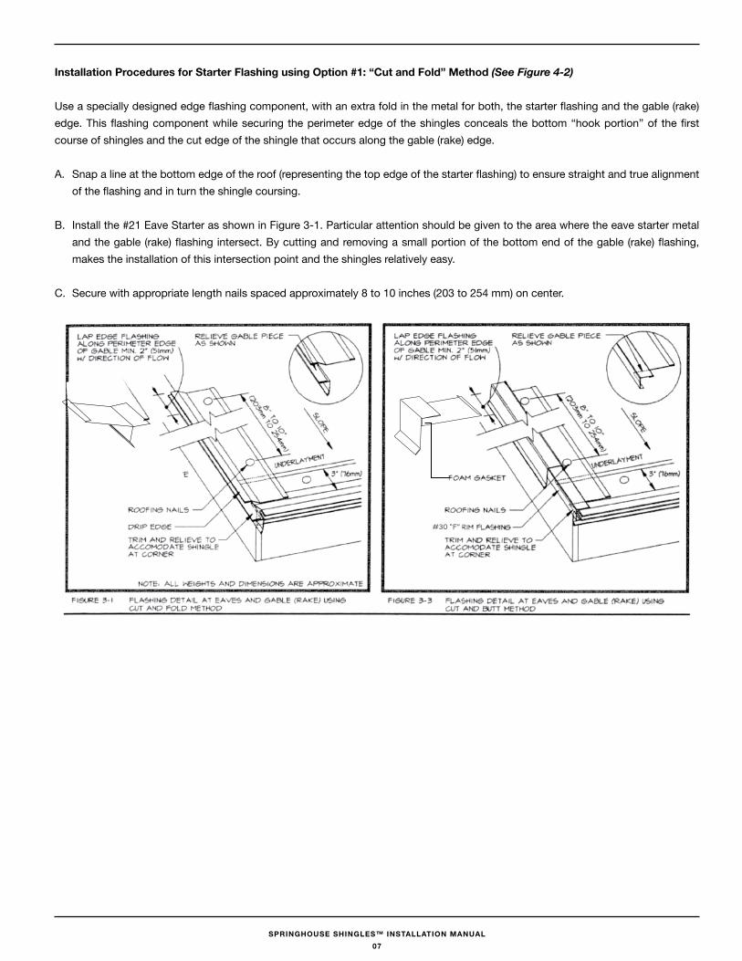
Installation Procedures for Starter flashing using Option #1: “Cut and fold” Method (See Figure 4-2)
Use a specially designed edge flashing component, with an extra fold in the metal for both, the starter flashing and the gable (rake) edge. This flashing component while securing the perimeter edge of the shingles conceals the bottom “hook portion” of the first course of shingles and the cut edge of the shingle that occurs along the gable (rake) edge.
A. Snap a line at the bottom edge of the roof (representing the top edge of the starter flashing) to ensure straight and true alignment of the flashing and in turn the shingle coursing.
B. Install the #21 Eave Starter as shown in Figure 3-1. Particular attention should be given to the area where the eave starter metal and the gable (rake) flashing intersect. By cutting and removing a small portion of the bottom end of the gable (rake) flashing, makes the installation of this intersection point and the shingles relatively easy.
C. Secure with appropriate length nails spaced approximately 8 to 10 inches (203 to 254 mm) on center.
#30 “F”
07
SPRINGHOUSE SHINGLES™ INSTALLATION MANUAL
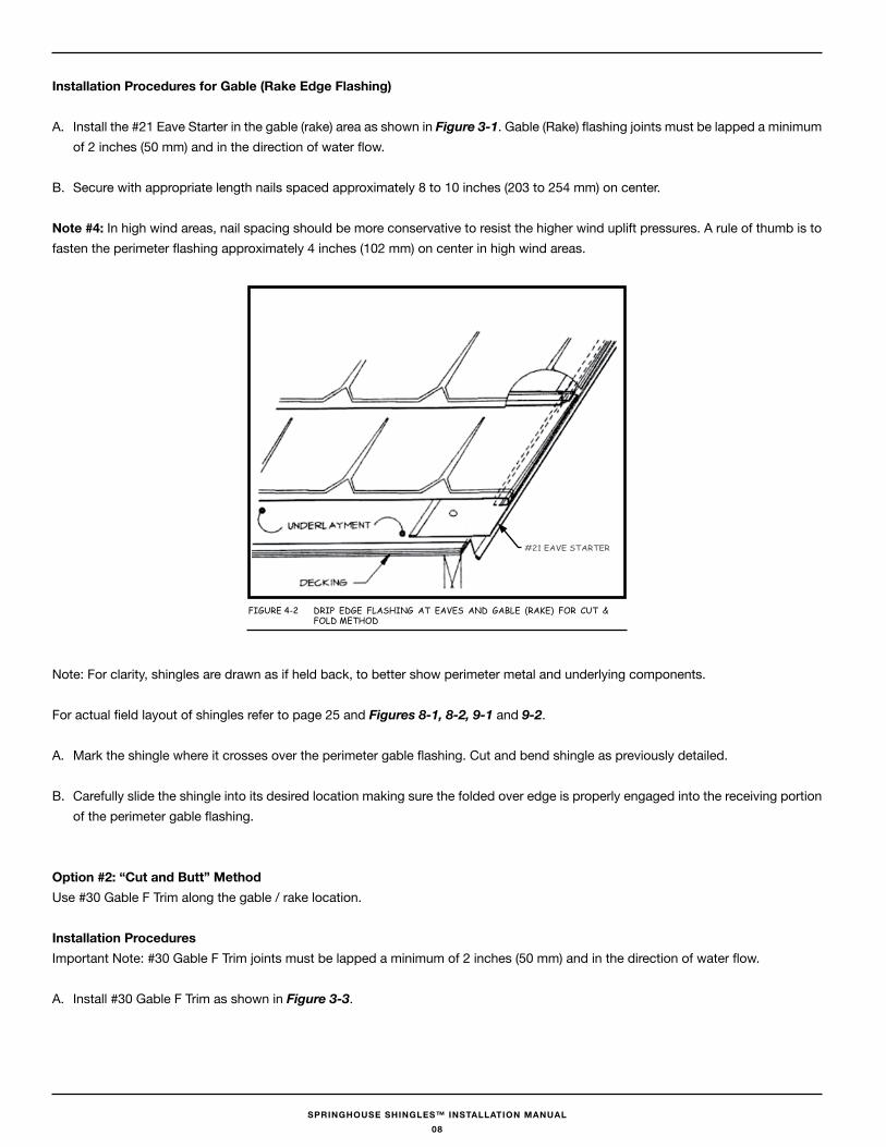
Installation Procedures for Gable (Rake Edge flashing)
A. Install the #21 Eave Starter in the gable (rake) area as shown in Figure 3-1. Gable (Rake) flashing joints must be lapped a minimum of 2 inches (50 mm) and in the direction of water flow.
B. Secure with appropriate length nails spaced approximately 8 to 10 inches (203 to 254 mm) on center.
Note #4: In high wind areas, nail spacing should be more conservative to resist the higher wind uplift pressures. A rule of thumb is to fasten the perimeter flashing approximately 4 inches (102 mm) on center in high wind areas.
Note: For clarity, shingles are drawn as if held back, to better show perimeter metal and underlying components.
For actual field layout of shingles refer to page 25 and Figures 8-1, 8-2, 9-1 and 9-2.
A. Mark the shingle where it crosses over the perimeter gable flashing. Cut and bend shingle as previously detailed.
B. Carefully slide the shingle into its desired location making sure the folded over edge is properly engaged into the receiving portion of the perimeter gable flashing.
Option #2: “Cut and butt” MethodUse #30 Gable F Trim along the gable / rake location.
Installation ProceduresImportant Note: #30 Gable F Trim joints must be lapped a minimum of 2 inches (50 mm) and in the direction of water flow.
A. Install #30 Gable F Trim as shown in Figure 3-3.
Figure 4-2 DriP eDge FLASHiNg AT eAVeS AND gABLe (rAKe) FOr CuT & FOLD MeTHOD
#21 eAVe STArTer
08
SPRINGHOUSE SHINGLES™ INSTALLATION MANUAL
Installation of Shingles Along The Gable (Rake) Using Option #2: “Cut and butt” Method
A. Properly position the shingle in the desired location. Mark the shingle where it crosses over the “J” trim and add approximately 1/2” to this mark. This line should be tapered from smaller at the bottom edge to larger at the top edge and represents where the cutting of the shingle will occur. Proceed with cutting the shingle along this line.
B. Using lock form pliers or bending bar, fold up the end of the shingle that will be inserted into the “J” trim. See Figure 12-2.
C. Carefully slide the shingle into its desired location. Adding 1/2” bend to the shingle ensures that additional protection by the shingle into the “J” trim and adequate compression of the sealing foam strip located in the “J” trim.
D. Proceed on up the gable with each succeeding shingle being marked, cut, bent, and carefully slid into its proper location.
valleysValleys exist where two sloping roofs intersect. Depending upon the layout of the intersecting roof areas, water runoff from the portions of the roof areas sloping into the valley generally runs off toward and along the valley. This results in runoff that accumulates in the valley, making the valley especially vulnerable to leakage. A clear, unobstructed drainage way is most desired so the valley may carry water away quickly and perform successfully for the life of the roof.
Valleys are constructed only after the necessary layer(s) of underlayment, have been applied to the deck. See Figure 2-2.
Note #5: In climate areas prone to accumulations of snow and ice, or with regular freeze-thaw cycling during the winter months, it has become fairly common to enhance open valley construction by lining by the valley with a self-adhering modified bitumen membrane High Temperature before application of the metal valley.
Installation of Metal valley
A. Use the #10 24” W Valley with folds incorporated to use the cut and fold method. Place the first piece of valley metal into valley area. Position metal properly so valley is straight and true and temporarily fix into position. Mark and cut away the required relief necessary at the lower end of the valley metal to conform to the down slope roof perimeter. Please note that the #10 24” valley is tapered and is marked on the reverse side.
Important - be sure the relief cut will allow the valley metal to protrude past the drip edge by a minimum of 3⁄4”. With the use of an extended metal drip edge, it can be beneficial to “lock” a portion of the valley metal to the perimeter by bending it over the extended edge.
B. Succeeding valley metal lengths should overlap underlying lengths by at least 8 inches (205 mm) and blind fasten each section across its upper end. Fastening at this time should only occur along the top of the piece being installed. Continue to install the remainder of the valley metal, keeping in mind the valley should be straight and true.
Note #6: If tapering the lines together towards the top of the valley, at a rate of 1/8 inch per foot, use the Rigid Valley in conjunction with valley cleats, this will cause the shingles to flare apart from top to bottom and thus eliminating the possibility of edges catching water or debris.
09
SPRINGHOUSE SHINGLES™ INSTALLATION MANUAL
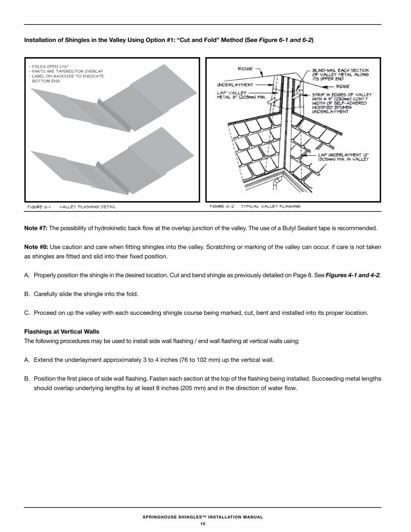
Installation of Shingles in the valley Using Option #1: “Cut and fold” Method (See Figure 6-1 and 6-2)
Note #7: The possibility of hydrokinetic back flow at the overlap junction of the valley. The use of a Butyl Sealant tape is recommended.
Note #8: Use caution and care when fitting shingles into the valley. Scratching or marking of the valley can occur, if care is not taken as shingles are fitted and slid into their fixed position.
A. Properly position the shingle in the desired location. Cut and bend shingle as previously detailed on Page 8. See Figures 4-1 and 4-2.
B. Carefully slide the shingle into the fold.
C. Proceed on up the valley with each succeeding shingle course being marked, cut, bent and installed into its proper location.
flashings at vertical walls The following procedures may be used to install side wall flashing / end wall flashing at vertical walls using;
A. Extend the underlayment approximately 3 to 4 inches (76 to 102 mm) up the vertical wall.
B. Position the first piece of side wall flashing. Fasten each section at the top of the flashing being installed. Succeeding metal lengths should overlap underlying lengths by at least 8 inches (205 mm) and in the direction of water flow.
– FOLDS OPeN 1/16”– PArTS Are TAPereD FOr OVerLAP– LABeL ON BACKSiDe TO iNDiCATe BOTTOM eND
10
SPRINGHOUSE SHINGLES™ INSTALLATION MANUAL
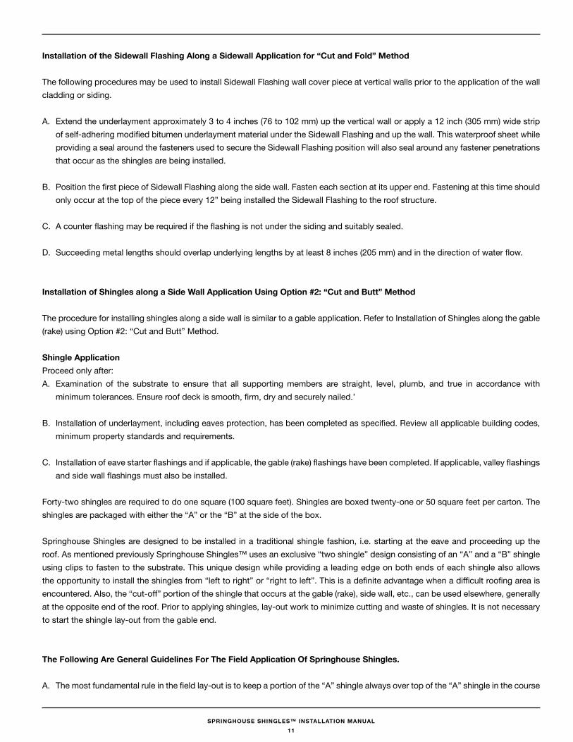
Installation of the Sidewall flashing Along a Sidewall Application for “Cut and fold” Method
The following procedures may be used to install Sidewall Flashing wall cover piece at vertical walls prior to the application of the wall cladding or siding.
A. Extend the underlayment approximately 3 to 4 inches (76 to 102 mm) up the vertical wall or apply a 12 inch (305 mm) wide strip of self-adhering modified bitumen underlayment material under the Sidewall Flashing and up the wall. This waterproof sheet while providing a seal around the fasteners used to secure the Sidewall Flashing position will also seal around any fastener penetrations that occur as the shingles are being installed.
B. Position the first piece of Sidewall Flashing along the side wall. Fasten each section at its upper end. Fastening at this time should only occur at the top of the piece every 12” being installed the Sidewall Flashing to the roof structure.
C. A counter flashing may be required if the flashing is not under the siding and suitably sealed.
D. Succeeding metal lengths should overlap underlying lengths by at least 8 inches (205 mm) and in the direction of water flow.
Installation of Shingles along a Side wall Application Using Option #2: “Cut and butt” Method
The procedure for installing shingles along a side wall is similar to a gable application. Refer to Installation of Shingles along the gable (rake) using Option #2: “Cut and Butt” Method.
Shingle ApplicationProceed only after:A. Examination of the substrate to ensure that all supporting members are straight, level, plumb, and true in accordance with
minimum tolerances. Ensure roof deck is smooth, firm, dry and securely nailed.’
B. Installation of underlayment, including eaves protection, has been completed as specified. Review all applicable building codes, minimum property standards and requirements.
C. Installation of eave starter flashings and if applicable, the gable (rake) flashings have been completed. If applicable, valley flashings and side wall flashings must also be installed.
Forty-two shingles are required to do one square (100 square feet). Shingles are boxed twenty-one or 50 square feet per carton. The shingles are packaged with either the “A” or the “B” at the side of the box.
Springhouse Shingles are designed to be installed in a traditional shingle fashion, i.e. starting at the eave and proceeding up the roof. As mentioned previously Springhouse Shingles™ uses an exclusive “two shingle” design consisting of an “A” and a “B” shingle using clips to fasten to the substrate. This unique design while providing a leading edge on both ends of each shingle also allows the opportunity to install the shingles from “left to right” or “right to left”. This is a definite advantage when a difficult roofing area is encountered. Also, the “cut-off” portion of the shingle that occurs at the gable (rake), side wall, etc., can be used elsewhere, generally at the opposite end of the roof. Prior to applying shingles, lay-out work to minimize cutting and waste of shingles. It is not necessary to start the shingle lay-out from the gable end.
The following Are General Guidelines for The field Application Of Springhouse Shingles.
A. The most fundamental rule in the field lay-out is to keep a portion of the “A” shingle always over top of the “A” shingle in the course
11
SPRINGHOUSE SHINGLES™ INSTALLATION MANUAL
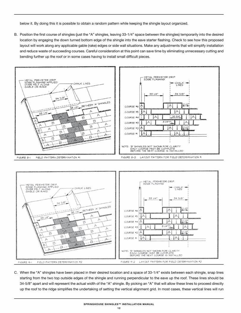
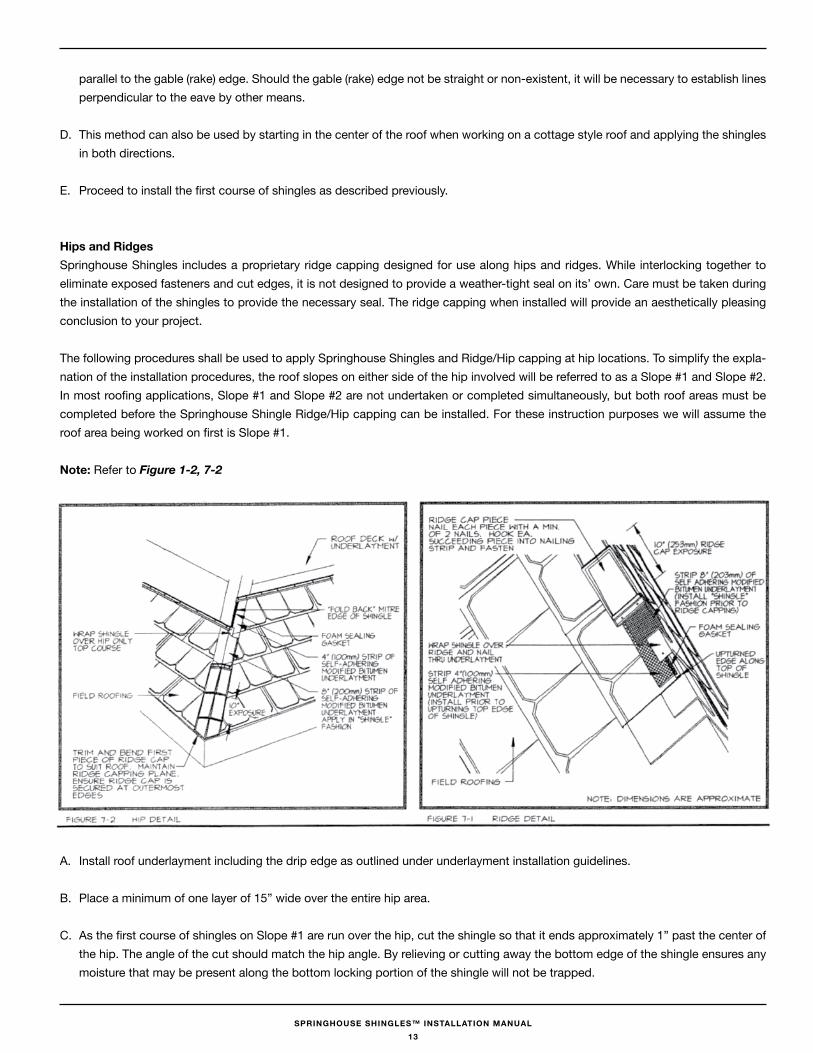
below it. By doing this it is possible to obtain a random pattern while keeping the shingle layout organized.
B. Position the first course of shingles (just the “A” shingles, leaving 33-1/4” space between the shingles) temporarily into the desired location by engaging the down turned bottom edge of the shingle into the eave starter flashing. Check to see how this proposed layout will work along any applicable gable (rake) edges or side wall situations. Make any adjustments that will simplify installation and reduce waste of succeeding courses. Careful consideration at this point can save time by eliminating unnecessary cutting and bending further up the roof or in some cases having to install small difficult pieces.
C. When the “A” shingles have been placed in their desired location and a space of 33-1/4” exists between each shingle, snap lines starting from the two top outside edges of the shingle and running perpendicular to the eave up the roof. These lines should be 34-5/8” apart and will represent the actual width of the “A” shingle. By picking an “A” that will allow these lines to proceed directly up the roof to the ridge simplifies the undertaking of setting the vertical alignment grid. In most cases, these vertical lines will run
12
SPRINGHOUSE SHINGLES™ INSTALLATION MANUAL
parallel to the gable (rake) edge. Should the gable (rake) edge not be straight or non-existent, it will be necessary to establish lines perpendicular to the eave by other means.
D. This method can also be used by starting in the center of the roof when working on a cottage style roof and applying the shingles in both directions.
E. Proceed to install the first course of shingles as described previously.
Hips and RidgesSpringhouse Shingles includes a proprietary ridge capping designed for use along hips and ridges. While interlocking together to eliminate exposed fasteners and cut edges, it is not designed to provide a weather-tight seal on its’ own. Care must be taken during the installation of the shingles to provide the necessary seal. The ridge capping when installed will provide an aesthetically pleasing conclusion to your project.
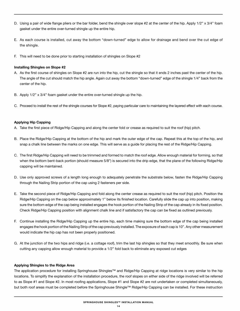
The following procedures shall be used to apply Springhouse Shingles and Ridge/Hip capping at hip locations. To simplify the expla-nation of the installation procedures, the roof slopes on either side of the hip involved will be referred to as a Slope #1 and Slope #2. In most roofing applications, Slope #1 and Slope #2 are not undertaken or completed simultaneously, but both roof areas must be completed before the Springhouse Shingle Ridge/Hip capping can be installed. For these instruction purposes we will assume the roof area being worked on first is Slope #1.
Note: Refer to Figure 1-2, 7-2
A. Install roof underlayment including the drip edge as outlined under underlayment installation guidelines.
B. Place a minimum of one layer of 15” wide over the entire hip area.
C. As the first course of shingles on Slope #1 are run over the hip, cut the shingle so that it ends approximately 1” past the center of the hip. The angle of the cut should match the hip angle. By relieving or cutting away the bottom edge of the shingle ensures any moisture that may be present along the bottom locking portion of the shingle will not be trapped.
13
SPRINGHOUSE SHINGLES™ INSTALLATION MANUAL
D. Using a pair of wide flange pliers or the bar folder, bend the shingle over slope #2 at the center of the hip. Apply 1/2” x 3/4” foam gasket under the entire over-turned shingle up the entire hip.
E. As each course is installed, cut away the bottom “down-turned” edge to allow for drainage and bend over the cut edge of the shingle.
F. This will need to be done prior to starting installation of shingles on Slope #2
Installing Shingles on Slope #2A. As the first course of shingles on Slope #2 are run into the hip, cut the shingle so that it ends 2 inches past the center of the hip.
The angle of the cut should match the hip angle. Again cut away the bottom “down-turned” edge of the shingle 1/4” back from the center of the hip.
B. Apply 1/2” x 3/4” foam gasket under the entire over-turned shingle up the hip.
C. Proceed to install the rest of the shingle courses for Slope #2, paying particular care to maintaining the layered effect with each course.
Applying Hip CappingA. Take the first piece of Ridge/Hip Capping and along the center fold or crease as required to suit the roof (hip) pitch.
B. Place the Ridge/Hip Capping at the bottom of the hip and mark the outer edge of the cap. Repeat this at the top of the hip, and snap a chalk line between the marks on one edge. This will serve as a guide for placing the rest of the Ridge/Hip Capping.
C. The first Ridge/Hip Capping will need to be trimmed and formed to match the roof edge. Allow enough material for forming, so that when the bottom bent-back portion (should measure 5/8”) is secured into the drip edge, that the plane of the following Ridge/Hip capping will be maintained.
D. Use only approved screws of a length long enough to adequately penetrate the substrate below, fasten the Ridge/Hip Capping through the Nailing Strip portion of the cap using 2 fasteners per side.
E. Take the second piece of Ridge/Hip Capping and fold along the center crease as required to suit the roof (hip) pitch. Position the Ridge/Hip Capping on the cap below approximately 1” below its finished location. Carefully slide the cap up into position, making sure the bottom edge of the cap being installed engages the hook portion of the Nailing Strip of the cap already in its fixed position. Check Ridge/Hip Capping position with alignment chalk line and if satisfactory the cap can be fixed as outlined previously.
F. Continue installing the Ridge/Hip Capping up the entire hip, each time making sure the bottom edge of the cap being installed engages the hook portion of the Nailing Strip of the cap previously installed. The exposure of each cap is 10”. Any other measurement would indicate the hip cap has not been properly positioned.
G. At the junction of the two hips and ridge (i.e. a cottage roof), trim the last hip shingles so that they meet smoothly. Be sure when cutting any capping allow enough material to provide a 1/2” fold back to eliminate any exposed cut edges
Applying Shingles to the Ridge Area The application procedure for installing Springhouse Shingles™ and Ridge/Hip Capping at ridge locations is very similar to the hip locations. To simplify the explanation of the installation procedure, the roof slopes on either side of the ridge involved will be referred to as Slope #1 and Slope #2. In most roofing applications, Slope #1 and Slope #2 are not undertaken or completed simultaneously, but both roof areas must be completed before the Springhouse Shingle™ Ridge/Hip Capping can be installed. For these instruction
14
SPRINGHOUSE SHINGLES™ INSTALLATION MANUAL
purposes we will assume the roof area being worked on first is Slope #1.
A. Install roof underlayment including the drip edge as outlined under underlayment installation guidelines.
B. Place a minimum of one layer of 18” wide s self-adhering modified bitumen membrane over the entire ridge area.
C. As the last course of shingles on Slope #1 are run up to the ridge, cut the top of the shingle so that it ends approximately 1” past the center of the ridge.
D. Bend it over the ridge and apply a 1/2” x 3/4” foam gasket under the shingle for the entire length of the ridge.
E. Proceed to install the rest of the shingles, making sure to apply the 1/2” x 3/4” foam gasket.
Installing Shingles on Slope #2A. As the last course of shingles on Slope #2 are run up to the ridge, cut the shingle so that it ends 2 inches past the center of the
ridge. Fold this portion of the shingle over the ridge and over the foam gasket onto Slope #1.
B. Apply a 9 inch wide strip of self-adhering modified bitumen membrane. This membrane is installed over the center of the ridge (i.e. covering a portion of Slope # 1 and Slope #2)
Applying Ridge/Hip Capping Along the RidgeA. Take the first piece of Ridge/Hip Capping and along the center fold or crease as required to suit the roof (ridge) pitch.
B. Place a piece of Ridge/Hip Capping at one end of the ridge and mark the outer edge of the cap. Repeat this at the other end of the ridge, and snap a chalk line between the two marks on one edge. This will serve as a guide for placing the rest of the Ridge/Hip Capping.
C. The first Ridge/Hip Capping may need to be trimmed and formed to match the roof edge. Cut and form as necessary so that when installed, the unsecured end of the cap is engaged into the receiving edge of the gable flashing.
D. Using only approved nails or screws of a length long enough to adequately penetrate the substrate below, fasten the Ridge/Hip Capping through the Nailing Strip portion of the cap using 2 fasteners per side.
E. Take the second piece of Ridge/Hip Capping and fold along the center crease as required to suit the roof (ridge) pitch. Position the Ridge/Hip Capping on the cap below, approximately, 1 inch past its finished location. Carefully slide the cap up into position, making sure the bottom edge of the cap being installed engages the hook portion of the Nailing Strip of the cap already in its fixed position. Check Ridge/Hip Capping position with alignment chalk line and if satisfactory the cap can be fixed as outlined previously.
F. Continue installing the Ridge/Hip Capping up the entire ridge, each time making sure the bottom edge of the cap being installed engages the hook portion of the Nailing Strip of the cap previously installed. The exposure of each cap is 10 inches. Any other measurement would indicate the hip cap has not been properly positioned.
G. The only two fasteners exposed on the entire roof will be the two that secure the last piece of Ridge/Hip Capping in place. Cover with a sealant suitable for this application and in a colour to match the roof.
15
SPRINGHOUSE SHINGLES™ INSTALLATION MANUAL
Installing Ridge ventilation using Rapid Ridge™A. Cut a 3” opening at the ridge peak and allow for a closed area of the sheathing 18” from each ends of the ridge.
B. Place a minimum of one layer of 9” wide self-adhering modified bitumen membrane over the shingle to the ridge opening along the entire ridge area.
C. As the last course of shingles on Slope #1 are run up to the ridge opening, cut the top of the shingle so that it ends approximately 1” past the opening of the ridge.
D. Using a pair of wide flange pliers or the bar folder, bend the shingle 180 degrees back toward the eave at the opening of the ridge.
E. Proceed to install the rest of the shingles on Slope #1.
F. This will need to be done prior to starting installation of shingles on Slope #2.
Installing Shingles on Slope #2A. As the last course of shingles on Slope #2 are run up to the ridge opening, cut the top of the shingle so that it ends approximately
1” past the opening of the ridge.
B. Using a pair of wide flange pliers or the bar folder, bend the shingle 180 degrees back toward the eave at the opening of the ridge.
Applying Rapid Ridge™A. Insert the Rapid Ridge into SH-09 Rapid Ridge Cover and allow a 12” “splice” between the metal ridge.
B. Apply Butyl Sealant 3/32” x ½” to the foremost flat portion closest to the eave of the Rapid Ridge™
C. Use #9 x 1.5” Painted Woodgrips through the Metal Ridge and the Butyl Sealant into the substrate every 18”. Be careful not to over torque the fastener and keep the ridge crisp and even.
D. Apply Suprathermik sealant to the ends of each ridge cover.
flashing Around ChimneysMasonry chimneys are usually built on a separate structural support or foundation from that of the building’s foundation. The chimneyis normally subject to some differential settling, and flashing the location where the chimney projects through the roof requires a typeof construction that will allow for movement without damage to the weather-tight integrity of the roof and associated flashings aroundthe chimney. To satisfy this requirement, four separate types of flashings should be installed around the chimney. Generally, the four flashings are referred to as:
* Endwall Flashing; that is installed at the down slope of the chimney* Step Flashing; that is installed up the sides of the chimney* Back Pan Flashing; that is installed is installed on the up-slope side or back of the chimney* Sidewall Flashing; that is installed over the step flashing* Counter Flashing; that is installed above and over the End wall, Back Pan, Sidewall flashing by cutting a raglet in the chimney
Depending upon the size of the chimney, a cricket may need to be installed at the up-slope side of the chimney. A cricket is designed to direct water runoff around the chimney. Install crickets when any of the following criteria are present. The chimney is more than 24inches (610 mm) wide.
16
SPRINGHOUSE SHINGLES™ INSTALLATION MANUAL
The roof slope is 6 inches per foot (50%) or greater.
The mean January temperature is 30° F (-1° C) or lower and significant accumulations of snow and ice are anticipated on the up-slopeside of the chimney.
Generally, before any flashings are applied, a self-adhering modified bitumen membrane High Temperature, should be applied to theroof deck around the chimney. If appropriately applied and constructed, an ice dam protection membrane can assist in keeping waterfrom migrating into the roof system at the intersection with the chimney during times of severe winter freeze-thaw cycling.
Chimney flashing ApplicationWhen the self-adhering modified bitumen membrane High Temperature has been installed, then the shingle and flashing applicationmay begin.
Endwall flashingInstall the SH-12 Chimney Endwall flashing, trim and notch the flashing to extend past the chimney on the roof and bend up the sidesInstall the End Wall flashing, trim and notch the flashing to extend past the chimney on the roof and bend up the sides up the side ofthe chimney a minimum of 8”, fasten on the roof. Apply a quality butyl sealant at each corner and up the roof.
Step flashingsStart the Step flashing over the End Wall flashing and apply a quality butyl sealant on each edge of the Step flashing. Continue witheach step flashing up the sides finishing at the top by trimming and bending around the top.
Installation of the Sidewall flashing at the Chimney Side wall Section(s) Application for “Cut and fold” Method
The following procedures may be used to install Sidewall Flashing side walls of the chimney prior to the shingles
A. Extend the underlayment approximately 3 to 4 inches (76 to 102 mm) up the vertical wall or apply a 12 inch (305 mm) wide strip of self-adhering modified bitumen underlayment High Temperature material under the Sidewall Flashing and up the wall. This waterproof sheet while providing a seal around the fasteners used to secure the Sidewall Flashing position will also seal around any fastener penetrations that occur as the shingles are being installed.
B. Position the first piece of Sidewall Flashing along the side wall. Fasten each section at its upper end. Fastening at this time should only occur at the top of the piece every 12” being installed the Sidewall Flashing to the roof structure.
C. Succeeding metal lengths should overlap underlying lengths by at least 8 inches (205 mm) and in the direction of water flow.
Installation of a Sidewall Flashing at the Chimney Side Wall Section(s) Application Using Option #2 “Cut and Butt” Method. The procedure for installing shingles along a side wall is similar to a gable application. Refer to Installation of Shingles along the gable (rake) using Option #2: “Cut and Butt” Method.
back Pan flashingApply the Back Pan flashing around the down-slope side of the chimney. Springhouse Shingles™ recommends that the Back Pan flashing be formed so that the lower flange extends out beyond the chimney by at least 4” on each side. The vertical flange should extend at least 8 inches up the face of the chimney.
17
SPRINGHOUSE SHINGLES™ INSTALLATION MANUAL
When installing the shingles cut and fold the top portion of the back pan to align with the course of shingles, leaving a minimum of 4” of pan exposed to allow water and debris to clear. Use the shingle clips to secure the pan to the roof. The next course of shingles will hook into this fold.
On the sides of the back pan flashing fold to allow the shingles to cut and fold method to hook into the back pan flashing and incorporatingthe chimney side wall flashing.
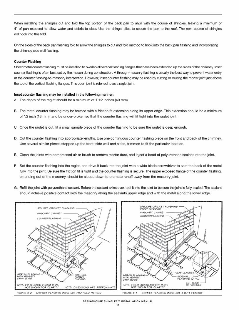
Counter flashingSheet metal counter flashing must be installed to overlap all vertical flashing flanges that have been extended up the sides of the chimney. Inset counter flashing is often best set by the mason during construction. A through-masonry flashing is usually the best way to prevent water entry at the counter flashing-to-masonry intersection. However, inset counter flashing may be used by cutting or routing the mortar joint just above the top of the vertical flashing flanges. This open joint is referred to as a raglet joint.
Inset counter flashing may be installed in the following manner:A. The depth of the raglet should be a minimum of 1 1⁄2 inches (40 mm).
B. The metal counter flashing may be formed with a friction fit extension along its upper edge. This extension should be a minimum of 1⁄2 inch (13 mm), and be under-broken so that the counter flashing will fit tight into the raglet joint.
C. Once the raglet is cut, fit a small sample piece of the counter flashing to be sure the raglet is deep enough.
D. Cut the counter flashing into appropriate lengths. Use one continuous counter flashing piece on the front and back of the chimney. Use several similar pieces stepped up the front, side wall and sides, trimmed to fit the particular location.
E. Clean the joints with compressed air or brush to remove mortar dust, and inject a bead of polyurethane sealant into the joint.
F. Set the counter flashing into the raglet, and drive it back into the joint with a wide blade screwdriver to seat the back of the metal fully into the joint. Be sure the friction fit is tight and the counter flashing is secure. The upper exposed flange of the counter flashing, extending out of the masonry, should be sloped down to promote runoff away from the masonry joint.
G. Refill the joint with polyurethane sealant. Before the sealant skins over, tool it into the joint to be sure the joint is fully sealed. The sealant should achieve positive contact with the masonry along the sealants upper edge and with the metal along the lower edge.
18
SPRINGHOUSE SHINGLES™ INSTALLATION MANUAL
Sheet Metal Cricket ApplicationA. When using a metal cricket flashing, the fabricated flashing should conform to the underlying sloped cricket substrate, and fit
snugly to the back of the chimney. The metal cricket must completely cover the underlying wood cricket substrate, extending beyond the valley center line and overlap onto the field of the main roof deck at least 6 inches (152 mm).
B. The vertical flange should extend a minimum of 6 inches (152 mm) up the back side of the chimney.
C. Apply the shingles up to and over the cricket.
Note: On relatively low slops in severe climates, Springhouse Shingles™ suggests that membrane strips be applied to the side and up-slope flanges that rest over the roof deck of the cricket flashing prior to application of the shingles. An effective technique for stripping in the flanges is to use 8 to 12 inch (203 to 305 mm) wide strips of a self-adhering modified asphalt membrane. If the flanges of the metal cricket are stripped-in, it may not be advisable to set the overlying shingles in asphalt roof cement, depending on the climate, roof layout and project conditions.
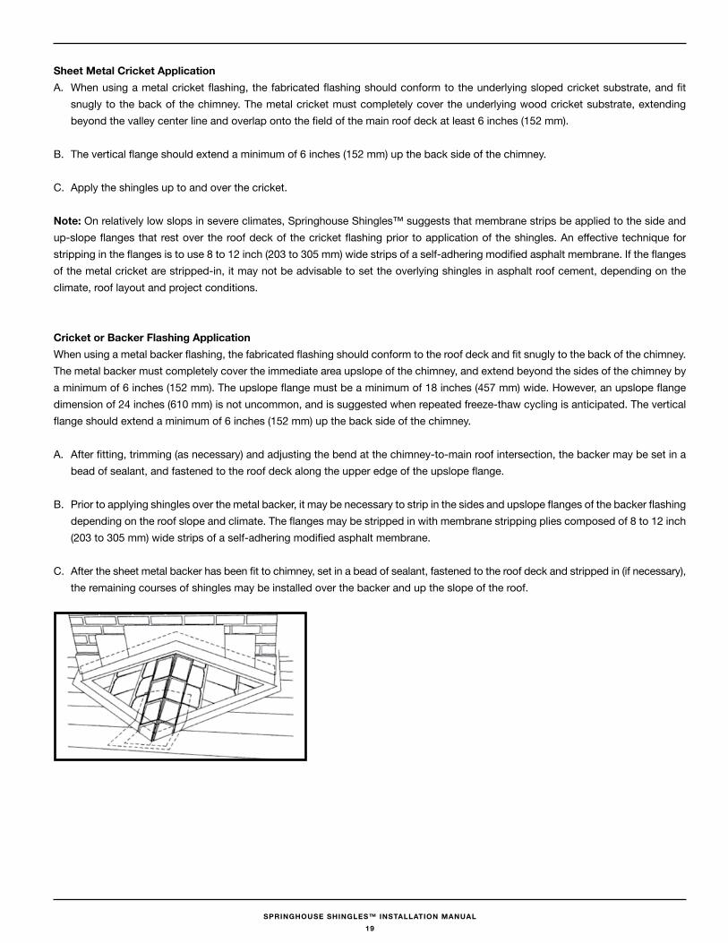
Cricket or backer flashing ApplicationWhen using a metal backer flashing, the fabricated flashing should conform to the roof deck and fit snugly to the back of the chimney. The metal backer must completely cover the immediate area upslope of the chimney, and extend beyond the sides of the chimney by a minimum of 6 inches (152 mm). The upslope flange must be a minimum of 18 inches (457 mm) wide. However, an upslope flange dimension of 24 inches (610 mm) is not uncommon, and is suggested when repeated freeze-thaw cycling is anticipated. The vertical flange should extend a minimum of 6 inches (152 mm) up the back side of the chimney.
A. After fitting, trimming (as necessary) and adjusting the bend at the chimney-to-main roof intersection, the backer may be set in a bead of sealant, and fastened to the roof deck along the upper edge of the upslope flange.
B. Prior to applying shingles over the metal backer, it may be necessary to strip in the sides and upslope flanges of the backer flashing depending on the roof slope and climate. The flanges may be stripped in with membrane stripping plies composed of 8 to 12 inch (203 to 305 mm) wide strips of a self-adhering modified asphalt membrane.
C. After the sheet metal backer has been fit to chimney, set in a bead of sealant, fastened to the roof deck and stripped in (if necessary), the remaining courses of shingles may be installed over the backer and up the slope of the roof.
19
SPRINGHOUSE SHINGLES™ INSTALLATION MANUAL
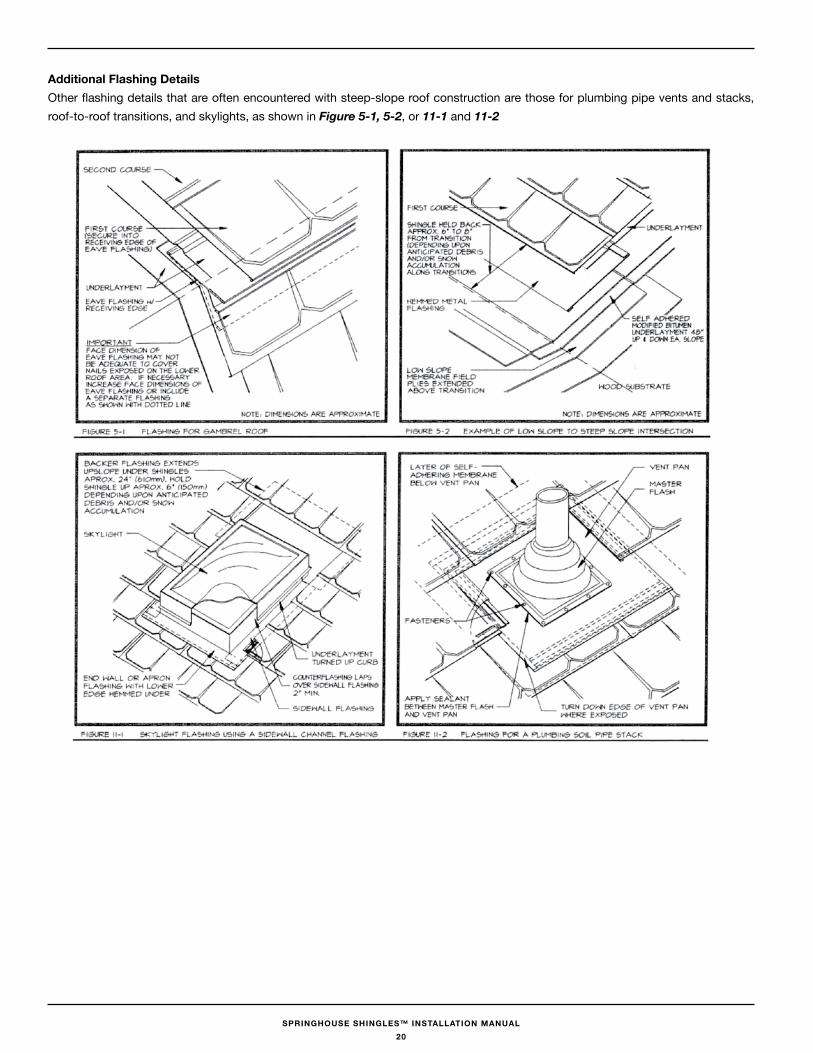
Additional flashing DetailsOther flashing details that are often encountered with steep-slope roof construction are those for plumbing pipe vents and stacks, roof-to-roof transitions, and skylights, as shown in Figure 5-1, 5-2, or 11-1 and 11-2
20
SPRINGHOUSE SHINGLES™ INSTALLATION MANUAL
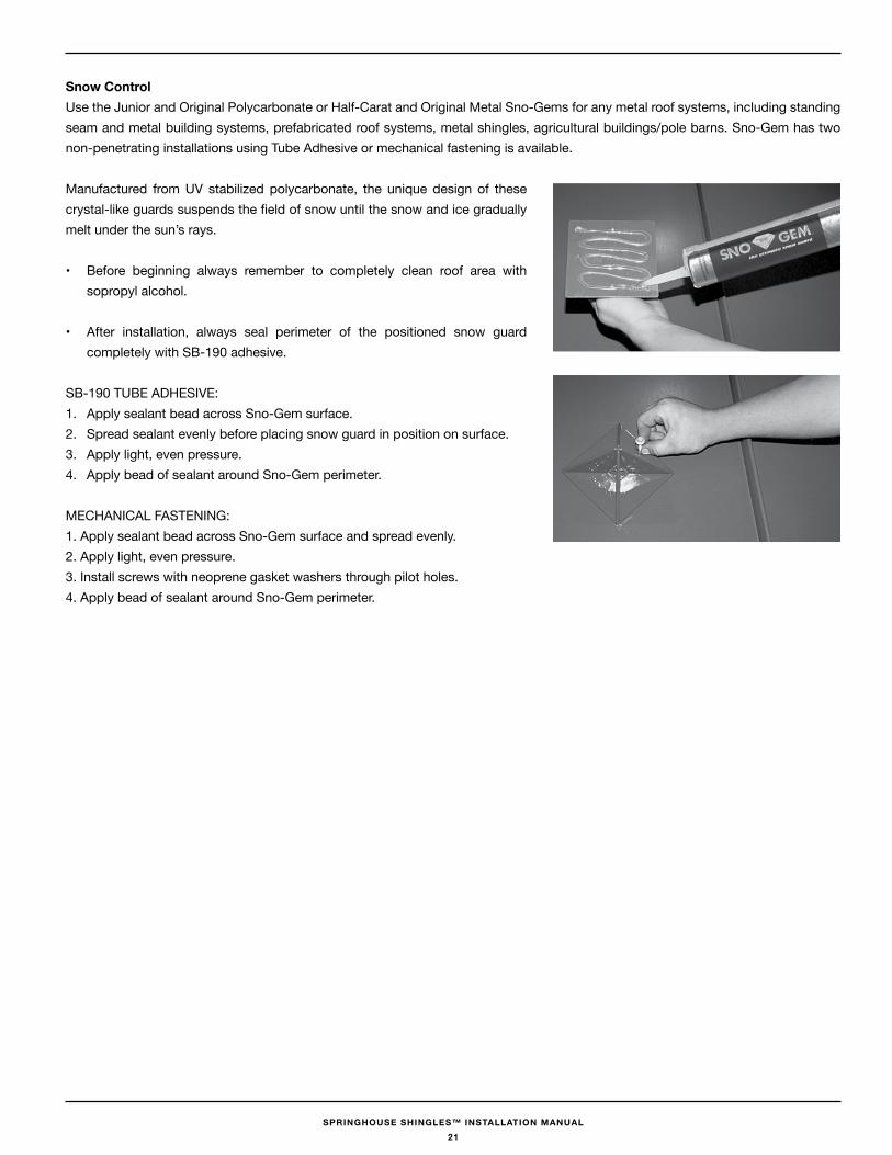
Snow Control Use the Junior and Original Polycarbonate or Half-Carat and Original Metal Sno-Gems for any metal roof systems, including standing seam and metal building systems, prefabricated roof systems, metal shingles, agricultural buildings/pole barns. Sno-Gem has two non-penetrating installations using Tube Adhesive or mechanical fastening is available.
Manufactured from UV stabilized polycarbonate, the unique design of these crystal-like guards suspends the field of snow until the snow and ice gradually melt under the sun’s rays.
• Before beginning always remember to completely clean roof area with sopropyl alcohol.
• After installation, always seal perimeter of the positioned snow guard completely with SB-190 adhesive.
SB-190 TUBE ADHESIVE:1. Apply sealant bead across Sno-Gem surface.2. Spread sealant evenly before placing snow guard in position on surface.3. Apply light, even pressure.4. Apply bead of sealant around Sno-Gem perimeter.
MECHANICAL FASTENING:1. Apply sealant bead across Sno-Gem surface and spread evenly.2. Apply light, even pressure.3. Install screws with neoprene gasket washers through pilot holes.4. Apply bead of sealant around Sno-Gem perimeter.
21

MEMBER
Agway Metals Inc.
170 Delta Park BlvdBrampton, ON L6T 5T61.800.268.2083
97 Thames Road EExeter, ON N0M 1S31.800.265.7070
agwaymetals.com