Embed Size (px)
Citation preview
1
SQUEEZE FILM DAMPERS: AN EXPERIMENTAL APPRAISAL OF THEIR DYNAMIC PERFORMANCE
Luis San Andrés Mast-Childs Chair Professor Turbomachinery Laboratory Mechanical Engineering Department Texas A&M University, College Station, TX 77845-3123 [email protected] Luis San Andrés performs research in the fields of fluid film lubrication and
rotordynamics, having advanced the technologies of hydrostatic bearings for primary power cryogenic turbo pumps, squeeze film dampers for aircraft jet engines, and gas foil bearings for oil-free micro turbomachinery. Luis is a Fellow of ASME and STLE, and a member of the Industrial Advisory Committees for the Texas A&M Turbomachinery Symposia. Dr. San Andrés has educated numerous graduate students who serve the profession with distinction. Dr. San Andrés earned a MS in ME from the University of Pittsburgh and a PhD in ME from Texas A&M University. Luis has published over 150 peer reviewed papers in various journals (ASME Journal of Tribology and ASME Journal of Gas Turbines and Power). Several papers are recognized as best in various international conferences.
Sung-hwa Jeung Graduate Research Assistant Turbomachinery Laboratory [email protected] Sung-Hwa Jeung received a B.S. degree in Mechanical Engineering from Korea University (Seoul) in 2010. Immediately after graduation, he worked as a mechanical engineer at Hyundai
Engineering Co., LTD. (2010-2011) before pursuing his graduate studies at Texas A&M University under Dr. San Andrés. He received a M.S. degree from Texas A&M University in 2013. Sung-Hwa went on to pursue a Ph.D. degree in Mechanical Engineering, and expects to finish in 2016. During the course of his research, he has authored several papers in ASME conferences, having won the Best Paper at the (2014) IFtoMM International Conference on Rotordynamics. His research mainly focuses on fluid film lubrication and rotordynamics in turbomachinery, in particular, experimental identification of forced performance of squeeze film dampers and its validation using computational analysis.
Sean Den Graduate Research Assistant Turbomachinery Laboratory [email protected] Sean Den was born and raised in Texas near the Houston area. He received his B.S. degree in Bioengineering at Rice University in May 2013. Influenced by summer internships in the oil and gas
industry, Sean developed an interest in rotating equipment. Subsequently, Sean enrolled at Texas A&M University in Fall 2013 to pursue a M.S. degree in Mechanical Engineering. Currently Sean works as a graduate research assistant at the Texas A&M University Turbomachinery Laboratory and will earn his M.S. degree in December 2015.
Gregory Savela Senior Technical Fellow Pratt & Whitney Engines, UTC East Hartford, CT 06118, USA [email protected] Gregory Savela is currently the Senior Fellow and Discipline Chief for Engine Dynamics and Loads at Pratt & Whitney, a division of United Technologies Corporation. Pratt & Whitney is a world
leader in the design, manufacture and service of aircraft engines and auxiliary power units. He has worked for Pratt & Whitney over twenty five years in the systems structures discipline working on the design-analysis and development-test of military and commercial engines. He also supports legacy products as well as the transition of development programs to full production, notably the Joint Strike Fighter F135 engine and an array of engine models in the Next Generation Product Family, or Geared TurboFan™. Gregory received his BSME from Michigan Technological University in 1983 and started work at Pratt & Whitney immediately thereafter, applying his system-design-analysis education to the development and application of advanced balance techniques and bearing-dampers to engine designs. It was in this early stage of his career that he was drawn to the rotor dynamics discipline owing to the impact of this on system level architecture and the interaction between component design level engineering and the rotor vibration behavior. Greg received his MSME from the University of Florida in 2000, concentrating on bearings and rotor dynamics to augment his practical experience in rotor dynamics and engine loads. Today he oversees the formal execution and review of rotor dynamics and loads work, consults on various rotor balance and engine vibration topics.
2
Abstract Squeeze Film Dampers (SFDs) are effective means to
ameliorate rotor vibration amplitudes and to suppress instabilities in rotor-bearing systems. A SFD is not an off-the-shelf mechanical element but tailored to a particular rotor-bearing system as its design must satisfy a desired damping ratio; if too low, the damper is ineffective, whereas if damping is too large, it locks the system aggravating the system response. In many cases, SFDs are also employed to control the placement of (rigid body) critical speeds displacing the machine operation into a speed range with effective structural isolation.
Industry demands well-engineered SFDs with a low footprint to reduce cost, maintenance, weight, and space while pushing for higher operating shaft speeds to increase power output. Compact aero jet engines implement ultra-short length SFDs (L/D ≤ 0.2) to satisfy stringent weight and space demands with low parts count. A manufacturer, as part of a business plan to develop and commercialize energy efficient aircraft gas turbine engines, supported a multiple–year project to test novel SFD design spaces.
In spite of the myriad of analyses and experimental result reported in the literature, there has not been to date a concerted effort to investigate the dynamic forced performance of a SFD through its many configurations: open ends vis-à-vis sealed ends conditions, and supply conditions with a fluid plenum or deep groove vis-à-vis feed holes directly impinging into the film land. This lecture presents experimental results obtained with a dedicated rig to evaluate short length SFDs operating under large dynamic loads (2.2 kN ≈ 500 lbf) that produced circular and elliptical whirl orbits of varying amplitude, centered and off-centered.
The lecture first reviews how SFDs work, placing emphasis on certain effects largely overlooked by practitioners who often regard the SFD as a simple non-rotating journal bearing. These effects are namely fluid inertia amplification in the supply or discharge grooves, pervasive air ingestion at high whirl frequencies, and effective end sealing means to enhance damping.
The bulk of the lecture presents for various SFD configurations comparisons of experimentally identified damping (C) and inertia or added mass (M) coefficients versus amplitude of motion (orbit size) and static eccentricity position, both ranging from small to large; as large as the film clearance! The experiments, conducted over six plus years of continued work give an answer to the following fundamental practitioners’ questions:
(a) Dampers don’t have a stiffness (static centering capability), how come?
(b) Why is there fluid inertia or added mass in a damper? Isn’t a damper a purely viscous element?
(c) How much do the damping and added mass change when the film length is halved? What about increasing the clearance to twice its original magnitude?
(d) How much more damping is available if the damper has end seals?
(e) Is a damper with feed holes as effective as one containing a groove that ensures lubricant pools to fill the film? What if a hole plugs, is a damper still effective?
(f) Do the amplitude and shape of whirl motion affect the damper force coefficients?
(g) What happens if the damper operates largely off-centered; does its performance become nonlinear?
(h) What do prevailing theoretical predictions correlate with the experimental record?
Introduction
Squeeze Film Dampers (SFD) aid to attenuate rotor synchronous response to imbalance and to suppress subsynchronous rotordynamic instability. Aircraft gas turbine engines employ one or more SFDs to provide external damping to rolling element bearings supporting a rotor. A SFD is not an off-the-shelf mechanical element but tailored to a particular rotor-bearing system as its design must satisfy a certain damping ratio1.
The amount of damping produced is the critical design consideration. If damping is too large, the SFD acts as a rigid constraint to the rotor-bearing system with large forces transmitted to the supporting structure. If damping is too light, the damper is ineffective and likely to permit large amplitudes of vibratory motion with likely subsynchronous motions. Note that to be effective, a damping element needs to be "soft", thus allowing for motion at the location of the support; in particular for the modes of vibration of interest [1].
In many cases, SFDs in conjunction with an elastic support (squirrel cage) are designed to control the placement of (rigid body) critical speeds, thus moving the machine operation into a speed range with effective structural isolation [1,2].
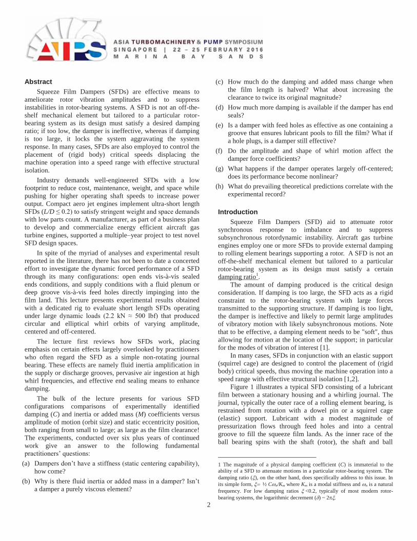
Figure 1 illustrates a typical SFD consisting of a lubricant film between a stationary housing and a whirling journal. The journal, typically the outer race of a rolling element bearing, is restrained from rotation with a dowel pin or a squirrel cage (elastic) support. Lubricant with a modest magnitude of pressurization flows through feed holes and into a central groove to fill the squeeze film lands. As the inner race of the ball bearing spins with the shaft (rotor), the shaft and ball
1 The magnitude of a physical damping coefficient (C) is immaterial to the ability of a SFD to attenuate motions in a particular rotor-bearing system. The damping ratio ( ), on the other hand, does specifically address to this issue. In its simple form, ½ C n/Km where Km is a modal stiffness and n is a natural frequency. For low damping ratios <0.2, typically of most modern rotor-bearing systems, the logarithmic decrement ( ) ~ 2
3
bearing outer race whirl together within the housing and thus squeeze the oil film. A dynamic pressure field generated by displacing the lubricant produces reaction forces that aid to damp excessive amplitudes of rotor whirl motion.
Fig. 1 Depiction of typical squeeze film dampers (a) with anti-rotation pin and (b) with elastic (centering) cage. Configurations (c) with a supply groove and open ends, (d) with a supply hole and end seals [2].
Zeidan et al. [1] in 1996 sum the historical development of SFDs since their second invention in the 1960’s and discuss the major technical issues for their integration in jet engines and compressors. Della Pietra and Adiletta [3,4] in 2002 provide a comprehensive survey of the theoretical models and (laboratory) experimental characterization of the SFD and its applications. Later, in 2012, San Andrés [2] presents details on the fluid flow models for the prediction of SFD performance, discuss major issues related to fluid inertia and the outstanding differences between lubricant cavitation (vapor or gas) and gas ingestion and entrapment in the fluid film. Ref. [2] lists formulas for the evaluation of (open ends) SFD force coefficients operating fully submerged in a lubricant pool, thus prone to show lubricant vapor cavitation. The equations, drawn from early analytical research in the 1980’s [5] are frequently cited for SFD design and prediction of performance.
In 2010, Vance et al. [6] correct the record and inform the first SFD was invented by Sir Charles Algerson Parsons in 1889 and incorporated into the first practical steam turbine. Ref. [6] details applications of SFDs to optimize the damping ratio and stability in compressors as well as to shift critical speeds. Recently (2013), Childs [7] gives a detailed account of the invention of a SFD by Parsons and presents case studies of successful implementation of SFDs into compressors and steam turbines. Childs draws knowledge from research on SFDs conducted at Texas A&M University (TAMU) by John Vance and his students, and later by Luis San Andrés and collaborators. Childs also stresses the differences between oil cavitation and air ingestion and their profound impact on the
kinetics of SFDs. In particular, the experimental work has evidenced SFDs are not as non-linear as classical lubrication theory predicts. The main section of this lecture will make apparent the basis for the assertion.
Note that since 1975, the TAMU Turbomachinery Symposium has also showcased numerous lectures describing applications of SFDs to rotating machinery, in particular steam turbines and compressors. For a concise review of these lectures, read Refs. [6,7] or access the papers2 directly at http://turbolab.tamu.edu/proc/. SFD forces and linearized force coefficients
Fluid film journal bearings provide low friction as well as load support, static and dynamic, to rotating machinery. These mechanical elements provide reaction forces F={FX, FY}T
, typically modeled as
( )t eF =F -K z -Cz-Mzz-Mz (1) where Fe is a static reaction force at an equilibrium position and z={x, y}T are journal center motions about an equilibrium position. The 4x4 matrices K, C and M contain the stiffness, damping and inertia force coefficients, respectively. Fluid inertia or added mass coefficients (M) are significant in SFDs and annular seals with dense fluids, for example [2]. Force coefficients are paramount to the design and reliability analysis of high performance rotor-bearing systems. The linearized representation allows the prediction of rotordynamic synchronous response and system stability.
The magnitude and direction of the fluid film reaction force generated by a SFD depends not only on the damper geometry, lubricant viscosity and journal kinematics, but also on the disposition of supply and discharge grooves, lubricant density and supply pressure, oil delivery arrangement, and the persistence of air ingestion or lubricant cavitation or both, see Refs. [2-4]. Alas industry relies on analyses that regard SFDs as a simplified version of a hydrodynamic journal bearing, effectively ignoring the effects listed above. Thus, it is not surprising the claim that correlation between measured SFD performance and predictions still remains poor [6,7].
Is a SFD a non-spinning journal bearing?
A journal bearing and a squeeze film damper have apparently a similar configuration, i.e., a lubricant film enclosed between a journal and a bearing housing. However, both mechanical elements work in distinct ways. Over decades, practitioners simply regarded the SFD as a journal bearing and made unsound generalizations about its behavior. The obvious difference between both components is that in a journal bearing the shaft spins with angular speed ( ), whereas the journal
2 URL http://www.rotordynamics.org is a useful search engine to find technical material (conference papers) on rotordynamics, bearings and seals.
4
center in a damper can only displace and whirl or precess within its clearance.
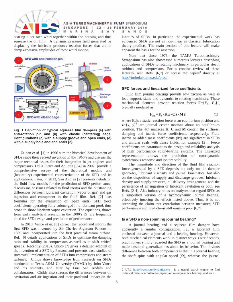
Figure 2 depicts the generation of viscous hydrodynamic pressure in a journal bearing whose center is displaced to static eccentricity (es) within the clearance (c). The change in static position – from its center, makes a hydrodynamic wedge where the fluid flow decelerates to generate a pressure field; the peak pressure locates just upstream of the minimum film thickness. In the region where the gap increases, the lubricant cavitates as it cannot sustain tension. In the schematic view shown, the integration of the pressure field on the journal force produces a reaction force (Fs) that balances the applied static load Ws.
Fig. 2. Schematic view of static pressure field in a hydrodynamic journal bearing and balance of forces. Film or gap exaggerated.
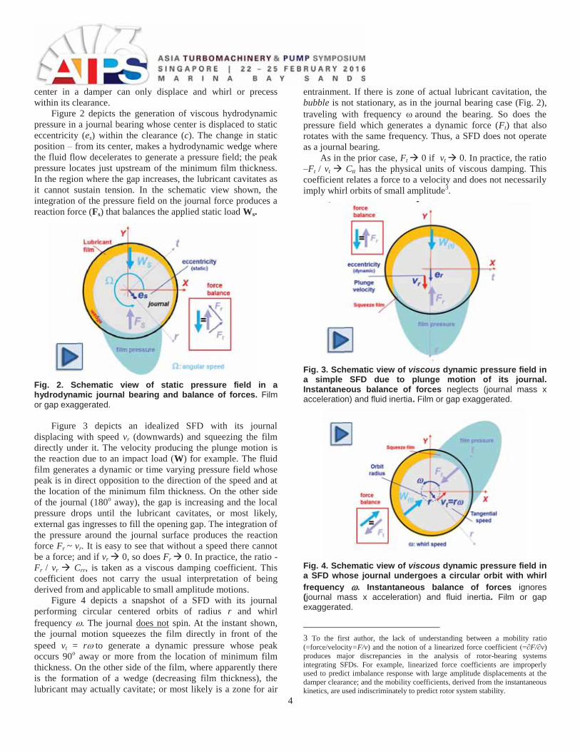
Figure 3 depicts an idealized SFD with its journal displacing with speed vr (downwards) and squeezing the film directly under it. The velocity producing the plunge motion is the reaction due to an impact load (W) for example. The fluid film generates a dynamic or time varying pressure field whose peak is in direct opposition to the direction of the speed and at the location of the minimum film thickness. On the other side of the journal (180o away), the gap is increasing and the local pressure drops until the lubricant cavitates, or most likely, external gas ingresses to fill the opening gap. The integration of the pressure around the journal surface produces the reaction force Fr ~ vr. It is easy to see that without a speed there cannot be a force; and if vr 0, so does Fr 0. In practice, the ratio -Fr / vr Crr, is taken as a viscous damping coefficient. This coefficient does not carry the usual interpretation of being derived from and applicable to small amplitude motions.
Figure 4 depicts a snapshot of a SFD with its journal performing circular centered orbits of radius r and whirl frequency . The journal does not spin. At the instant shown, the journal motion squeezes the film directly in front of the speed vt = r to generate a dynamic pressure whose peak occurs 90o away or more from the location of minimum film thickness. On the other side of the film, where apparently there is the formation of a wedge (decreasing film thickness), the lubricant may actually cavitate; or most likely is a zone for air
entrainment. If there is zone of actual lubricant cavitation, the bubble is not stationary, as in the journal bearing case (Fig. 2), traveling with frequency around the bearing. So does the pressure field which generates a dynamic force (Ft) that also rotates with the same frequency. Thus, a SFD does not operate as a journal bearing.
As in the prior case, Ft 0 if vt 0. In practice, the ratio –Ft / vt Ctt has the physical units of viscous damping. This coefficient relates a force to a velocity and does not necessarily imply whirl orbits of small amplitude3.
Fig. 3. Schematic view of viscous dynamic pressure field in a simple SFD due to plunge motion of its journal. Instantaneous balance of forces neglects (journal mass x acceleration) and fluid inertia. Film or gap exaggerated.
Fig. 4. Schematic view of viscous dynamic pressure field in a SFD whose journal undergoes a circular orbit with whirl frequency . Instantaneous balance of forces ignores (journal mass x acceleration) and fluid inertia. Film or gap exaggerated.
3 To the first author, the lack of understanding between a mobility ratio (=force/velocity=F/v) and the notion of a linearized force coefficient (=∂F/∂v) produces major discrepancies in the analysis of rotor-bearing systems integrating SFDs. For example, linearized force coefficients are improperly used to predict imbalance response with large amplitude displacements at the damper clearance; and the mobility coefficients, derived from the instantaneous kinetics, are used indiscriminately to predict rotor system stability.
5
Incidentally, it is important to realize that for a journal bearing spinning with speed and whirling with frequency and instantaneous eccentricity e=r, lubrication theory [8] demonstrates the generated hydrodynamic pressure (and reaction force) is proportional to speed [e (½ - )]. Hence, a SFD whirling with radius r and frequency will produce twice the force than a journal bearing statically off-centered to eccentricity e=r and spinning with angular speed
Fluid inertia effect in a SFD; when is it important? The discussion above does not include the effect of fluid
inertia on the force generation of a SFD. Classical lubrication theory ignores this effect as the thin fluid flow is too slow for fluid inertia to be important, i.e., the Reynolds number Re*= c2) This condition is generally true for most hydrodynamic journal bearings, but not so for SFDs on account of their larger clearance. In practice, dampers operate with a large squeeze film Reynolds number,4 Res= c2) > 1. For example, in aircraft engines, a high whirl frequency and low kinematic viscosity ( ) of the lubricants employed makes Res ~20-50 [2].
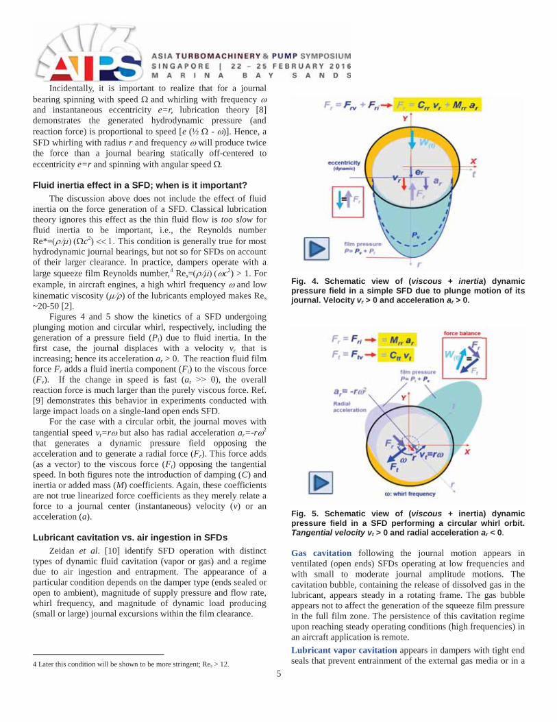
Figures 4 and 5 show the kinetics of a SFD undergoing plunging motion and circular whirl, respectively, including the generation of a pressure field (Pi) due to fluid inertia. In the first case, the journal displaces with a velocity vr that is increasing; hence its acceleration ar > 0. The reaction fluid film force Fr adds a fluid inertia component (Fi) to the viscous force (Fv). If the change in speed is fast (ar >> 0), the overall reaction force is much larger than the purely viscous force. Ref. [9] demonstrates this behavior in experiments conducted with large impact loads on a single-land open ends SFD.
For the case with a circular orbit, the journal moves with tangential speed vt=r but also has radial acceleration ar=-r 2 that generates a dynamic pressure field opposing the acceleration and to generate a radial force (Fr). This force adds (as a vector) to the viscous force (Ft) opposing the tangential speed. In both figures note the introduction of damping (C) and inertia or added mass (M) coefficients. Again, these coefficients are not true linearized force coefficients as they merely relate a force to a journal center (instantaneous) velocity (v) or an acceleration (a).
Lubricant cavitation vs. air ingestion in SFDs Zeidan et al. [10] identify SFD operation with distinct
types of dynamic fluid cavitation (vapor or gas) and a regime due to air ingestion and entrapment. The appearance of a particular condition depends on the damper type (ends sealed or open to ambient), magnitude of supply pressure and flow rate, whirl frequency, and magnitude of dynamic load producing (small or large) journal excursions within the film clearance.
4 Later this condition will be shown to be more stringent; Res > 12.
Fig. 4. Schematic view of (viscous + inertia) dynamic pressure field in a simple SFD due to plunge motion of its journal. Velocity vr > 0 and acceleration ar > 0.
Fig. 5. Schematic view of (viscous + inertia) dynamic pressure field in a SFD performing a circular whirl orbit. Tangential velocity vt > 0 and radial acceleration ar < 0. Gas cavitation following the journal motion appears in ventilated (open ends) SFDs operating at low frequencies and with small to moderate journal amplitude motions. The cavitation bubble, containing the release of dissolved gas in the lubricant, appears steady in a rotating frame. The gas bubble appears not to affect the generation of the squeeze film pressure in the full film zone. The persistence of this cavitation regime upon reaching steady operating conditions (high frequencies) in an aircraft application is remote. Lubricant vapor cavitation appears in dampers with tight end seals that prevent entrainment of the external gas media or in a
6
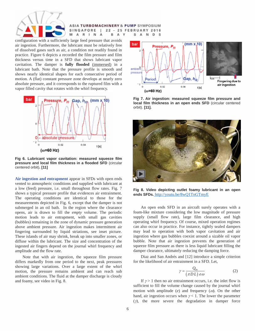
configuration with a sufficiently large feed pressure that avoids air ingestion. Furthermore, the lubricant must be relatively free of dissolved gases such as air, a condition not readily found in practice. Figure 6 depicts a recorded the film pressure and film thickness versus time in a SFD that shows lubricant vapor cavitation. The damper is fully flooded (immersed) in a lubricant bath. Note that the pressure profile is smooth and shows nearly identical shapes for each consecutive period of motion. A (flat) constant pressure zone develops at nearly zero absolute pressure, and it corresponds to the ruptured film with a vapor filled cavity that rotates with the whirl frequency.
Fig 6. Lubricant vapor cavitation: measured squeeze film pressure and local film thickness in a flooded SFD (circular centered orbit). [11]
Air ingestion and entrapment appear in SFDs with open ends vented to atmospheric conditions and supplied with lubricant at a low (feed) pressure, i.e. small throughout flow rates. Fig. 7 shows a typical pressure profile that evidences air entrainment. The operating conditions are identical to those for the measurements depicted in Fig. 6, except that the damper is not submerged in an oil bath. In the region where the clearance opens, air is drawn to fill the empty volume. The periodic motion leads to air entrapment, with small gas cavities (bubbles) remaining in the zone of dynamic pressure generation above ambient pressure. Air ingestion makes intermittent air fingering surrounded by liquid striations, see inset picture. These islands of air may shrink, break up into smaller zones, or diffuse within the lubricant. The size and concentration of the ingested air fingers depend on the journal whirl frequency and amplitude and the flow rate.
Note that with air ingestion, the squeeze film pressure differs markedly from one period to the next, peak pressures showing large variations. Over a large extent of the whirl motion, the pressure remains ambient and can reach sub ambient conditions. The fluid at the damper discharge is cloudy and foamy, see video in Fig. 8.
Fig 7. Air ingestion: measured squeeze film pressure and local film thickness in an open ends SFD (circular centered orbit). [11].
Fig 8. Video depicting outlet foamy lubricant in an open ends SFDs. http://youtu.be/8wQ1TnGTmyE
An open ends SFD in an aircraft surely operates with a foam-like mixture considering the low magnitude of pressure supply (small flow rate), large film clearance, and high operating whirl frequency. Of course, mixed operation regimes can also occur in practice. For instance, tightly sealed dampers may lead to operation with both vapor cavitation and air ingestion where gas bubbles coexist around a sizable oil vapor bubble. Note that air ingestion prevents the generation of squeeze film pressure as there is less liquid lubricant filling the damper clearance, ultimately reducing the damping force.
Diaz and San Andrés and [12] introduce a simple criterion for the likelihood of air entrainment in a SFD. Let,
inQD L e
(2)
If > 1 then no air entrainment occurs, i.e. the inlet flow is sufficient to fill the volume change caused by the journal whirl motion with amplitude (e) and frequency ( ). On the other hand, air ingestion occurs when < 1. The lower the parameter ( ), the more severe the degradation in damper force
7
performance. Air ingestion is device dependent, its severity increasing with the amplitude and frequency of journal motion. Air ingestion can be prevented by increasing the supply pressure (and supplied flow), an impractical condition in most applications.
Description of SFD test rig In 2008, an aircraft manufacturer contracted the Texas
A&M Turbomachinery Laboratory to investigate experimentally the dynamic force performance of SFDs, to advance the knowledge of damper performance and operation, and to integrate the knowledge (test data, analysis, and modeling) into their engineering design practice.
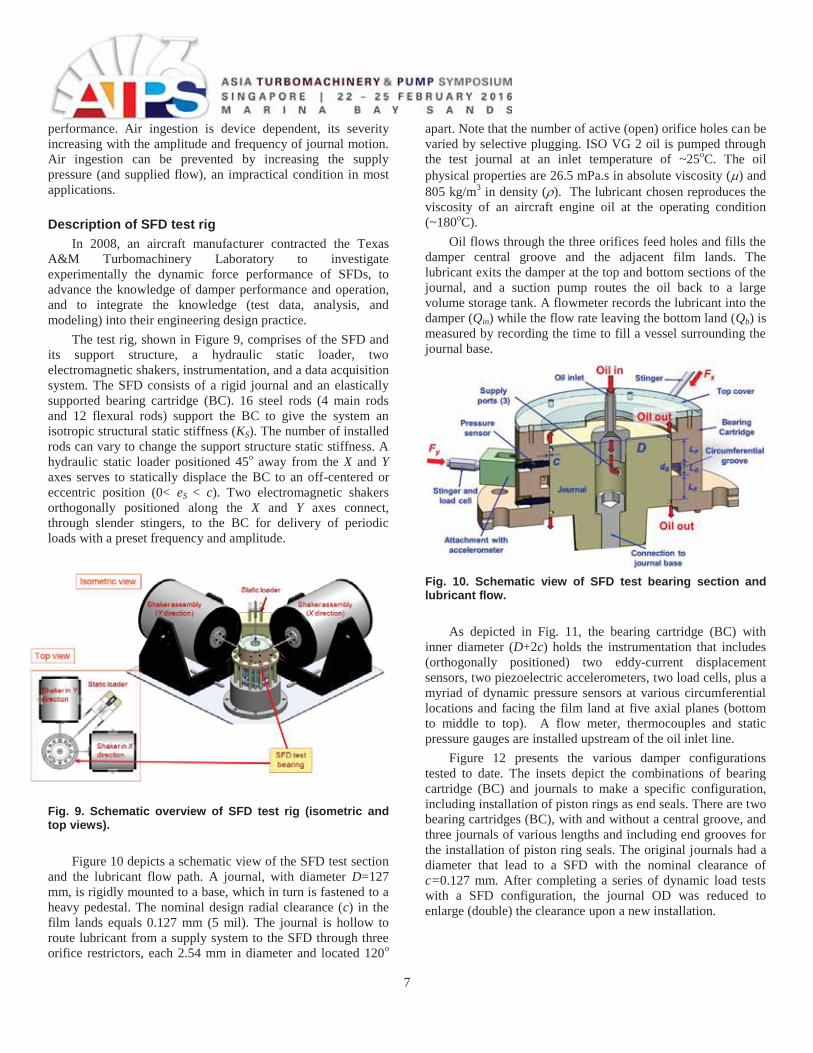
The test rig, shown in Figure 9, comprises of the SFD and its support structure, a hydraulic static loader, two electromagnetic shakers, instrumentation, and a data acquisition system. The SFD consists of a rigid journal and an elastically supported bearing cartridge (BC). 16 steel rods (4 main rods and 12 flexural rods) support the BC to give the system an isotropic structural static stiffness (KS). The number of installed rods can vary to change the support structure static stiffness. A hydraulic static loader positioned 45o away from the X and Y axes serves to statically displace the BC to an off-centered or eccentric position (0< eS < c). Two electromagnetic shakers orthogonally positioned along the X and Y axes connect, through slender stingers, to the BC for delivery of periodic loads with a preset frequency and amplitude.
Fig. 9. Schematic overview of SFD test rig (isometric and top views).
Figure 10 depicts a schematic view of the SFD test section and the lubricant flow path. A journal, with diameter D=127 mm, is rigidly mounted to a base, which in turn is fastened to a heavy pedestal. The nominal design radial clearance (c) in the film lands equals 0.127 mm (5 mil). The journal is hollow to route lubricant from a supply system to the SFD through three orifice restrictors, each 2.54 mm in diameter and located 120o
apart. Note that the number of active (open) orifice holes can be varied by selective plugging. ISO VG 2 oil is pumped through the test journal at an inlet temperature of ~25oC. The oil physical properties are 26.5 mPa.s in absolute viscosity ( ) and 805 kg/m3 in density ( ). The lubricant chosen reproduces the viscosity of an aircraft engine oil at the operating condition (~180oC).
Oil flows through the three orifices feed holes and fills the damper central groove and the adjacent film lands. The lubricant exits the damper at the top and bottom sections of the journal, and a suction pump routes the oil back to a large volume storage tank. A flowmeter records the lubricant into the damper (Qin) while the flow rate leaving the bottom land (Qb) is measured by recording the time to fill a vessel surrounding the journal base.
Fig. 10. Schematic view of SFD test bearing section and lubricant flow.
As depicted in Fig. 11, the bearing cartridge (BC) with inner diameter (D+2c) holds the instrumentation that includes (orthogonally positioned) two eddy-current displacement sensors, two piezoelectric accelerometers, two load cells, plus a myriad of dynamic pressure sensors at various circumferential locations and facing the film land at five axial planes (bottom to middle to top). A flow meter, thermocouples and static pressure gauges are installed upstream of the oil inlet line.
Figure 12 presents the various damper configurations tested to date. The insets depict the combinations of bearing cartridge (BC) and journals to make a specific configuration, including installation of piston rings as end seals. There are two bearing cartridges (BC), with and without a central groove, and three journals of various lengths and including end grooves for the installation of piston ring seals. The original journals had a diameter that lead to a SFD with the nominal clearance of c=0.127 mm. After completing a series of dynamic load tests with a SFD configuration, the journal OD was reduced to enlarge (double) the clearance upon a new installation.
8
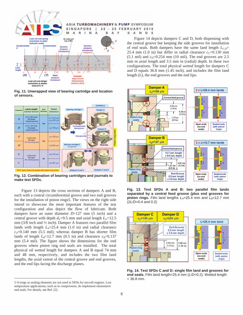
Fig. 11. Unwrapped view of bearing cartridge and location of sensors.
Fig. 12. Combination of bearing cartridges and journals to make test SFDs.
Figure 13 depicts the cross sections of dampers A and B, each with a central circumferential groove and two end grooves for the installation of piston rings5. The views on the right side intend to showcase the most important features of the test configuration and also depict the flow of lubricant. Both dampers have an outer diameter D=127 mm (5 inch) and a central groove with depth dG=9.5 mm and axial length LG=12.5 mm (3/8 inch and ½ inch). Damper A features two parallel film lands with length LA=25.4 mm (1.0 in) and radial clearance cA=0.140 mm (5.5 mil); whereas damper B has shorter film lands of length LB=12.7 mm (0.5 in) and clearance cB=0.137 mm (5.4 mil). The figure shows the dimensions for the end grooves where piston ring end seals are installed. The total physical oil wetted length for dampers A and B equal 74 mm and 48 mm, respectively, and includes the two film land lengths, the axial extent of the central groove and end grooves, and the end lips facing the discharge planes.
5 O-rings as sealing elements are not used in SFDs for aircraft engines. Low temperature applications, such as in compressors, do implement elastomeric end seals. For details, see Ref. [2].
Figure 14 depicts dampers C and D, both dispensing with the central groove but keeping the side grooves for installation of end seals. Both dampers have the same land length LC,D= 25.4 mm (1.0 in) but differ in radial clearance cC=0.130 mm (5.1 mil) and cD=0.254 mm (10 mil). The end grooves are 2.5 mm in axial length and 3.5 mm in (radial) depth. In these two configurations. The total physical wetted length for dampers C and D equals 36.8 mm (1.45 inch), and includes the film land length (L), the end grooves and the end lips.
Fig. 13. Test SFDs A and B: two parallel film lands separated by a central feed groove (plus end grooves for piston rings. Film land lengths LA=25.4 mm and LB=12.7 mm (2L/D=0.4 and 0.2)
Fig. 14. Test SFDs C and D: single film land and grooves for end seals. Film land length=25.4 mm (L/D=0.2). Wetted length = 36.8 mm.
9
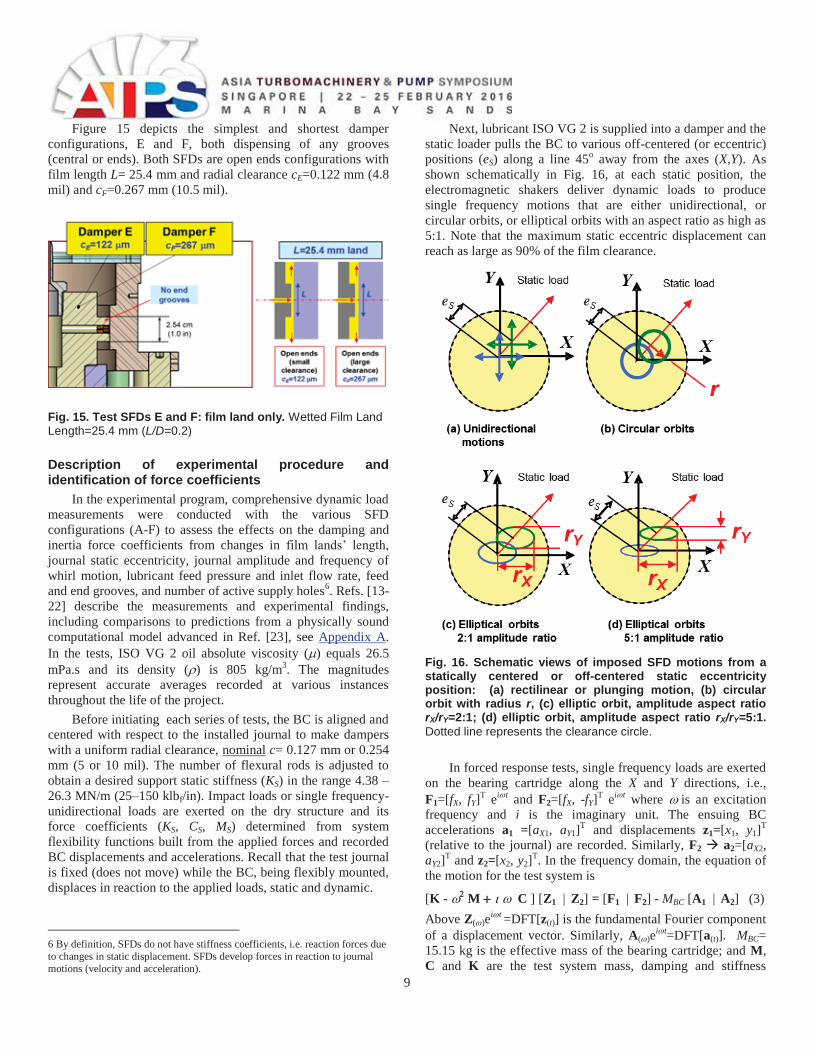
Figure 15 depicts the simplest and shortest damper configurations, E and F, both dispensing of any grooves (central or ends). Both SFDs are open ends configurations with film length L= 25.4 mm and radial clearance cE=0.122 mm (4.8 mil) and cF=0.267 mm (10.5 mil).
Fig. 15. Test SFDs E and F: film land only. Wetted Film Land Length=25.4 mm (L/D=0.2)
Description of experimental procedure and identification of force coefficients
In the experimental program, comprehensive dynamic load measurements were conducted with the various SFD configurations (A-F) to assess the effects on the damping and inertia force coefficients from changes in film lands’ length, journal static eccentricity, journal amplitude and frequency of whirl motion, lubricant feed pressure and inlet flow rate, feed and end grooves, and number of active supply holes6. Refs. [13-22] describe the measurements and experimental findings, including comparisons to predictions from a physically sound computational model advanced in Ref. [23], see Appendix A. In the tests, ISO VG 2 oil absolute viscosity ( ) equals 26.5 mPa.s and its density ( ) is 805 kg/m3. The magnitudes represent accurate averages recorded at various instances throughout the life of the project.
Before initiating each series of tests, the BC is aligned and centered with respect to the installed journal to make dampers with a uniform radial clearance, nominal c= 0.127 mm or 0.254 mm (5 or 10 mil). The number of flexural rods is adjusted to obtain a desired support static stiffness (KS) in the range 4.38 – 26.3 MN/m (25–150 klbf/in). Impact loads or single frequency-unidirectional loads are exerted on the dry structure and its force coefficients (KS, CS, MS) determined from system flexibility functions built from the applied forces and recorded BC displacements and accelerations. Recall that the test journal is fixed (does not move) while the BC, being flexibly mounted, displaces in reaction to the applied loads, static and dynamic.
6 By definition, SFDs do not have stiffness coefficients, i.e. reaction forces due to changes in static displacement. SFDs develop forces in reaction to journal motions (velocity and acceleration).
Next, lubricant ISO VG 2 is supplied into a damper and the static loader pulls the BC to various off-centered (or eccentric) positions (eS) along a line 45o away from the axes (X,Y). As shown schematically in Fig. 16, at each static position, the electromagnetic shakers deliver dynamic loads to produce single frequency motions that are either unidirectional, or circular orbits, or elliptical orbits with an aspect ratio as high as 5:1. Note that the maximum static eccentric displacement can reach as large as 90% of the film clearance.
Fig. 16. Schematic views of imposed SFD motions from a statically centered or off-centered static eccentricity position: (a) rectilinear or plunging motion, (b) circular orbit with radius r, (c) elliptic orbit, amplitude aspect ratio rX/rY=2:1; (d) elliptic orbit, amplitude aspect ratio rX/rY=5:1. Dotted line represents the clearance circle.
In forced response tests, single frequency loads are exerted on the bearing cartridge along the X and Y directions, i.e., F1=[fX, fY]T ei t and F2=[fX, -fY]T ei t where is an excitation frequency and i is the imaginary unit. The ensuing BC accelerations a1 =[aX1, aY1]T and displacements z1=[x1, y1]T (relative to the journal) are recorded. Similarly, F2 a2=[aX2, aY2]T and z2=[x2, y2]T. In the frequency domain, the equation of the motion for the test system is
[K - M C ] [Z1 | Z2] = [F1 | F2] - MBC [A1 | A2] (3) Above Z( )ei t =DFT[z(t)] is the fundamental Fourier component of a displacement vector. Similarly, A( )ei t=DFT[a(t)]. MBC= 15.15 kg is the effective mass of the bearing cartridge; and M, C and K are the test system mass, damping and stiffness
10
coefficients matrices. These matrices add the structural and SFD parameters, i.e.
M=MS+MSFD, K=KS+KSFD, C=CS+CSFD (4) The system complex stiffness matrix H=[K - M C ] is determined from solving
H( ) = [F1 | F2] [Z1 | Z2]-1 (5) at each whirl frequency ( ). The test procedure is performed over a range of whirl frequencies, from low to high, to build the complex stiffnesses H( ). Lastly, the system parameters are determined by curves that fit the real and imaginary parts of the complex stiffness: Re(H( )) K- M and Im(H( )) C, respectively. Correlation factors define the goodness of the physical model representing the test data. The physical parameters (K, C, M) are valid for the specified frequency range.
Taken the test system as linear allows the extraction of the SFD force coefficients from
(K, C, M) SFD = (K, C, M) – (K, C, M)S (6)
Note that the identified SFD force coefficients represent the combined action of the two parallel film lands (top and bottom), and whenever applicable, also include the effect of the central feed groove and end grooves.
In brief, the dry test system (A-B) has very little damping ( DRY < 0.03) with the system flexibilities (1/HS) showing large amplitudes at the system natural frequency. The lubricated test system is largely damped ( LUB > 0.5) with a lower (damped) natural frequency due to the apparent mass originating from fluid inertia in both the central groove and the film lands. The test system natural frequency depends on the structural stiffness of the elastic support systems, i.e., the number of bars used to assemble a particular configuration.
As will be shown later, for all damper configurations and most operating conditions, cross-coupled force coefficients are at least one order of magnitude lesser than the direct coefficients, thus considered negligible. The smallness of (CXY,CYX)SFD and (MXY,MYX)SFD demonstrate that the SFD operates without gaseous or vapor lubricant cavitation. Lubricated test system stiffness coefficients are often indistinguishable from the structural stiffnesses (KS), hence KSFD=0; except for whirl motions around a large static eccentricity (eS > 0.6 c).
The fact that KSFD~0 is a consequence of the experimental identification process and not a modeling assumption. Similarly, for most conditions CXY~0 and CYX~0 follows from Ima(CXY)~0 and Ima(CYX)~0. That is, the cross-coupled complex stiffness coefficients are much smaller in magnitude that their direct counterparts, |HXY( |HYX( |HXX( |HYY(
The experimental data and parameter identification evidence the test dampers do not behave as lubrication theory invoking the infamous -film model predicts, see Refs. [2,5] for example. The rationale for the apparent discrepancy is that for most operating conditions, the amplitudes of whirl motion
are not large enough to induce (enough) lubricant vaporization. On the other hand, air ingestion and entrapment is a pervasive issue for dynamic operation with large amplitude and a high whirl frequency, in particular for the open ends SFD configurations.
Refs. [13,17] report on the influence of the support structural stiffness on the dynamic response of the test system and provide extensive documentation on the uncertainty and repeatability of the experimental measurements.
Formulas for (gross) estimation of damping and inertia force coefficients
For an open ends SFD with finite film length (L), journal radius (R=½D), and radial clearance (c), the direct damping and inertia force coefficients for small amplitude motions (r 0) about the centered position (es=0) are [24]
3* * *
tanh12π 1XX YY
LR DC C C LLc D
(7a)
* * * 3tanh
π 1XX YY
LL DM M M RLc D
(7b)
The simple formulas do not account for either oil supply or `discharge grooves or any feed holes. They apply to a full film condition since small amplitude motions are unlikely to induce lubricant cavitation, either gas or vapor. For a short length film,
L/D 0,2
13
tanh1
LD L
DLD
, the formulas above
reduce to 3 3
* *0 0
1π ; π2 24L L
D D
D L LC M Dc c
(8)
The damping coefficient (C) is proportional to the lubricant viscosity x (L/c)3, whereas the inertia or added mass coefficient (M) ~ fluid density x (L3/c). It is important to realize the operating conditions when fluid inertia effects are important. For whirl motions with frequency ( ) and amplitude r, the ratio between the damper reaction radial force (Fr) and tangential force (Ft) is
3* 2 2s
3*
π Re1
12 1212π
r
t
LRM rF ccF C r RL
c
(9)
where Res= c2) is the squeeze film Reynolds number. Above vt=r is the journal center tangential velocity and ar=-r is its radial acceleration. Fluid inertia effects are dominant for operating conditions where Res>12.
Refs. [2,5] list formulas for prediction of force coefficients in short length, open ends SFDs (without means for lubricant
11
supply) as a function of the orbit radius or the static eccentricity (but not both). The equations are valid for operation with the film immersed in a lubricant bath, i.e., applicable for conditions where oil vapor cavitation would appear.
In the following, the force coefficients are shown normalized with respect to the physical magnitudes derived from Eqn. (8), i.e., C=C/C* and M=M/M*. The chosen normalization is a mere convenience for a general discussion of the experimental results.
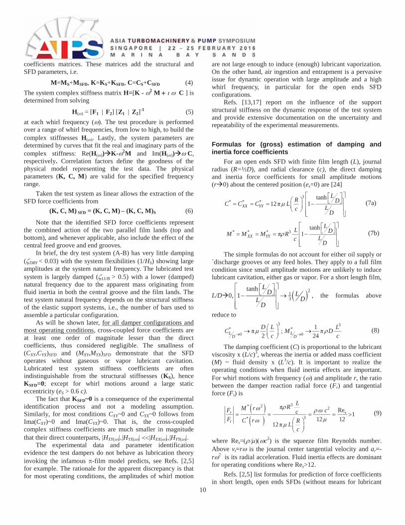
For a SFD with length L=25.4 mm, diameter D=127 mm, and nominal clearance c=0.127 mm, and material properties for ISO VG 2 oil, Eqn. (8) gives C*=3.09 kN·s/m (17.7 lbf.s/in) and M*=1.55 kg (3.4 lb). Figure 17 depicts the theoretical full film damping (C) and inertia (M) coefficients versus (a) orbit radius (r/c) for centered circular orbits (e=0), and (b) static eccentricity (e/c) for small amplitude motions (r 0). For small amplitude motions (r << c) about the centered condition, e~0, there is no distinction between both sets of force coefficients.
Fig. 17. Theory: Damping (C) and inertia (M) force coefficients for open ends dampers versus (a) orbit radius (r/c) and (b) static eccentricity (eX/c). L= 25.4 mm, L/D=0.2 and c/D=1/1000. ISO VG 2 oil at 25oC. Full film (no oil cavitation).
However, one realizes the damping force coefficients, in particular, are rather nonlinear as they vary rapidly with either an increase in orbit amplitude or when motions are around a large static eccentricity. Orbits with amplitude equal to 50% of the film clearance produce (theoretically) no less than a 50% increase in damping with respect to the centered condition. The differences exacerbate as the orbit radius (r) grows towards the clearance or the static eccentricity e c. Interestingly enough, the added mass coefficient (Mrr) decreases as the size of the orbit grows (r c), yet increase (mildly) with the static eccentricity.
The discussion of results below showcases the effect of the most important parameters affecting the forced performance of a SFD and addresses to the most pressing questions related to their operation; in particular its linear or nonlinear behavior. How do the damper force coefficients scale with film clearance?
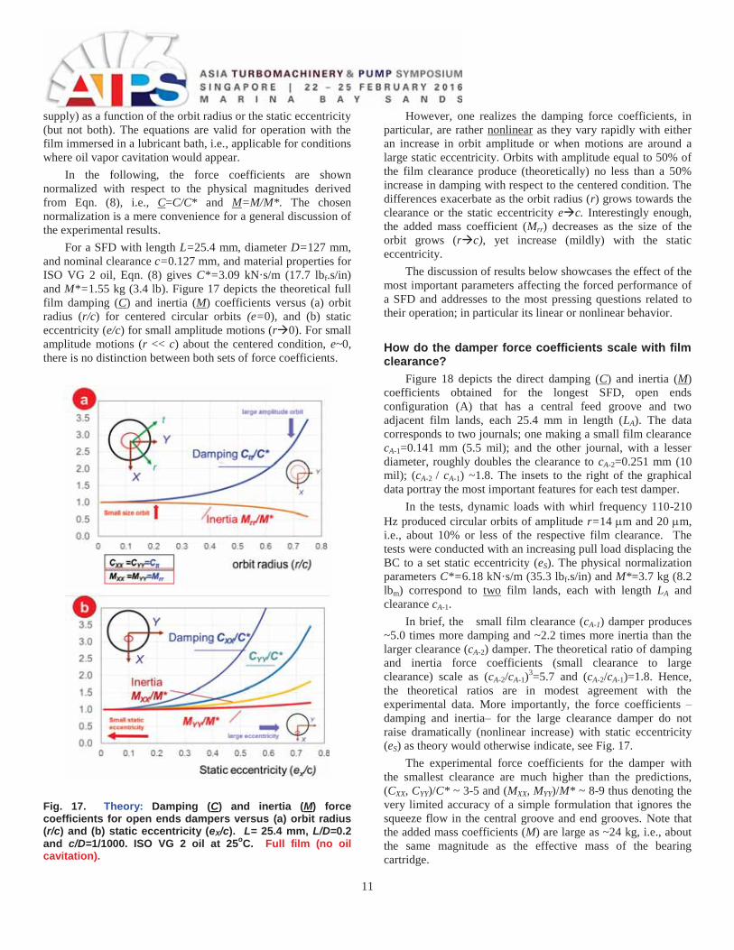
Figure 18 depicts the direct damping (C) and inertia (M) coefficients obtained for the longest SFD, open ends configuration (A) that has a central feed groove and two adjacent film lands, each 25.4 mm in length (LA). The data corresponds to two journals; one making a small film clearance cA-1=0.141 mm (5.5 mil); and the other journal, with a lesser diameter, roughly doubles the clearance to cA-2=0.251 mm (10 mil); (cA-2 / cA-1) ~1.8. The insets to the right of the graphical data portray the most important features for each test damper.
In the tests, dynamic loads with whirl frequency 110-210 Hz produced circular orbits of amplitude r=14 m and 20 m, i.e., about 10% or less of the respective film clearance. The tests were conducted with an increasing pull load displacing the BC to a set static eccentricity (eS). The physical normalization parameters C*=6.18 kN·s/m (35.3 lbf.s/in) and M*=3.7 kg (8.2 lbm) correspond to two film lands, each with length LA and clearance cA-1.
In brief, the small film clearance (cA-1) damper produces ~5.0 times more damping and ~2.2 times more inertia than the larger clearance (cA-2) damper. The theoretical ratio of damping and inertia force coefficients (small clearance to large clearance) scale as (cA-2/cA-1)3=5.7 and (cA-2/cA-1)=1.8. Hence, the theoretical ratios are in modest agreement with the experimental data. More importantly, the force coefficients – damping and inertia– for the large clearance damper do not raise dramatically (nonlinear increase) with static eccentricity (eS) as theory would otherwise indicate, see Fig. 17.
The experimental force coefficients for the damper with the smallest clearance are much higher than the predictions, (CXX, CYY)/C* ~ 3-5 and (MXX, MYY)/M* ~ 8-9 thus denoting the very limited accuracy of a simple formulation that ignores the squeeze flow in the central groove and end grooves. Note that the added mass coefficients (M) are large as ~24 kg, i.e., about the same magnitude as the effective mass of the bearing cartridge.
12
Fig. 18. Effect of film clearance (nominal and double) on the direct damping (C) and inertia (M) force coefficients for open ends damper A. Nominal clearances cA-1=0.141 mm (5.5 mil) and cA-2=0.251 mm (9.8 mil). Measurements conducted for increasing static eccentricity (eS/cA-2) and circular orbits with amplitude rmax ~0.1 cA-2.
How do the damper force coefficients scale with film land length?
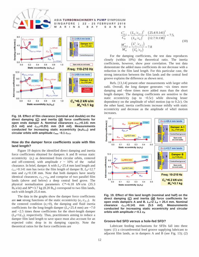
Figure 19 depicts the identified direct damping and inertia force coefficients obtained for dampers A and B versus static eccentricity (es) as determined from circular orbits, centered and off-centered, with amplitude r ~ 10% of the radial clearance. In brief, damper A with LA=25.4 mm land length and cA-1=0.141 mm has twice the film length of damper B, LB=12.7 mm and cB=0.138 mm. Note that both dampers have nearly identical clearances, cA-1~cB, and comprise of two parallel film lands (above and below) a deep central feed grove. The physical normalization parameters C*=6.18 kN·s/m (35.3 lbf.s/in) and M*=3.7 kg (8.20 lbm) correspond to two film lands, each with length 25.4 mm.
The data in the graphs show the damper force coefficients are not strong functions of the static eccentricity (eS /cA-1). At the centered condition (es=0), the damping and fluid inertia coefficients for the long-length damper (LA=25.4 mm) are ~7.0 and ~2.5 times those coefficients for the short-length damper (LB=½LA), respectively. Thus, practitioners aiming to reduce a damper film land length to save space must also account for an expected cubic drop in its damping capacity. Note the theoretical ratios for the force coefficients are
3 3*11
* 3 3
3*11
* 3
25.4 0.1417.5,
12.7 0.138
7.8A
A AA
B B B
AA
B B B
L cCC L c
L cMM L c
(10)
For the damping coefficients, the test data reproduces closely (within 10%) the theoretical ratio. The inertia coefficients, however, show poor correlation. The test data demonstrate the added mass coefficients do not decrease with a reduction in the film land length. For this particular case, the strong interaction between the film lands and the central feed groove explains the difference as shown next.
Refs. [13,14] present other measurements with larger orbit radii. Overall, the long damper generates ~six times more damping and ~three times more added mass than the short length damper. The damping coefficients are sensitive to the static eccentricity (up to ~0.5c) while showing lesser dependency on the amplitude of whirl motion (up to 0.2c). On the other hand, inertia coefficients increase mildly with static eccentricity and decrease as the amplitude of whirl motion increases.
Fig. 19. Effect of film land length (nominal and half) on the direct damping (C) and inertia (M) force coefficients for open ends dampers A and B. LA=2 LB = 25.4 mm. Nominal clearance cA-1=0.141 mm (5.5 mil). Measurements conducted for increasing static eccentricity and circular orbits with amplitude r~0.1 cB Groove-fed SFD versus a hole-fed SFD?
Lubricant feeding mechanisms for SFDs fall into three types: (1) a circumferential feed groove supplying lubricant to adjacent film lands, as in dampers A and B (see Fig. 13); (2)
13
feed orifices directly impinging into the mid plane of the film land length, as in dampers C-F (Figs. 14,15); and (3) a large plenum on the sides of the squeeze film land that delivers as much lubricant as needed. This last type, implying the damper is fully submerged in a bath of lubricant at a constant pressure, is difficult to realize; in particular in an aircraft engine where the lubricant delivered also supplies (and cools) the rolling element bearings. Note that the idealized condition (3) is the one exercised by countless analytical models that treat the damper with an open ends condition and no means for internal supply of lubricant (see discussion on predictive formulas).
As per a supply feed through a groove, engineering knowledge regards the deep volume as a constant pressure source that delivers flow –as much as needed– into the adjacent film lands, thus aiding to prevent lubricant starvation and/or cavitation. On the other hand, a (lengthwise) space-saving SFD dispenses with the groove and relies solely on feedholes to supply lubricant directly into the film land. Clearly, the flow resistance (diameter and length) of a feed orifice must be large enough to reduce back flow during instances when the squeeze film action pushes away the lubricant. Alas, a too small orifice demands of larger supply pressure to keep the desired flow. In an aircraft application, increases in oil delivery pressure and lubricant sump storage are prohibitive.
Conventional wisdom regards a deep groove as impervious to the kinematics of journal motion, it effectively isolates the adjacent film lands while supplying enough lubricant flow to permit an effective squeeze film action. For example, SFD A with two film lands separated by a deep groove should work as two independent dampers, each with its own land length. A number of archival publications, even textbooks, [5] show the following schematic views, Fig. 20, to emphasize the isolating character of a deep groove and also the large flow resistance of a tight end seal. Alas the information advanced for engineering practice is incorrect.
Fig. 20. Schematic views for generation of dynamic pressure in three damper configurations. Journal displaces towards bearing with speed v. Idealizations (b) and (c) are physically incorrect.
Presently, the questions addressed are: Does a central groove isolate a damper into two independent halves? Is a
damper with a central groove preferable to one without a feed groove?
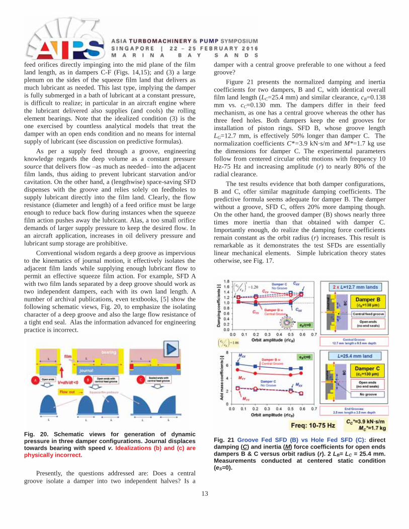
Figure 21 presents the normalized damping and inertia coefficients for two dampers, B and C, with identical overall film land length (LC=25.4 mm) and similar clearance, cB=0.138 mm vs. cC=0.130 mm. The dampers differ in their feed mechanism, as one has a central groove whereas the other has three feed holes. Both dampers keep the end grooves for installation of piston rings. SFD B, whose groove length LG=12.7 mm, is effectively 50% longer than damper C. The normalization coefficients C*=3.9 kN·s/m and M*=1.7 kg use the dimensions for damper C. The experimental parameters follow from centered circular orbit motions with frequency 10 Hz-75 Hz and increasing amplitude (r) to nearly 80% of the radial clearance.
The test results evidence that both damper configurations, B and C, offer similar magnitude damping coefficients. The predictive formula seems adequate for damper B. The damper without a groove, SFD C, offers 20% more damping though. On the other hand, the grooved damper (B) shows nearly three times more inertia than that obtained with damper C. Importantly enough, do realize the damping force coefficients remain constant as the orbit radius (r) increases. This result is remarkable as it demonstrates the test SFDs are essentially linear mechanical elements. Simple lubrication theory states otherwise, see Fig. 17.
Fig. 21 Groove Fed SFD (B) vs Hole Fed SFD (C): direct damping (C) and inertia (M) force coefficients for open ends dampers B & C versus orbit radius (r). 2 LB= LC = 25.4 mm. Measurements conducted at centered static condition (eS=0).
14
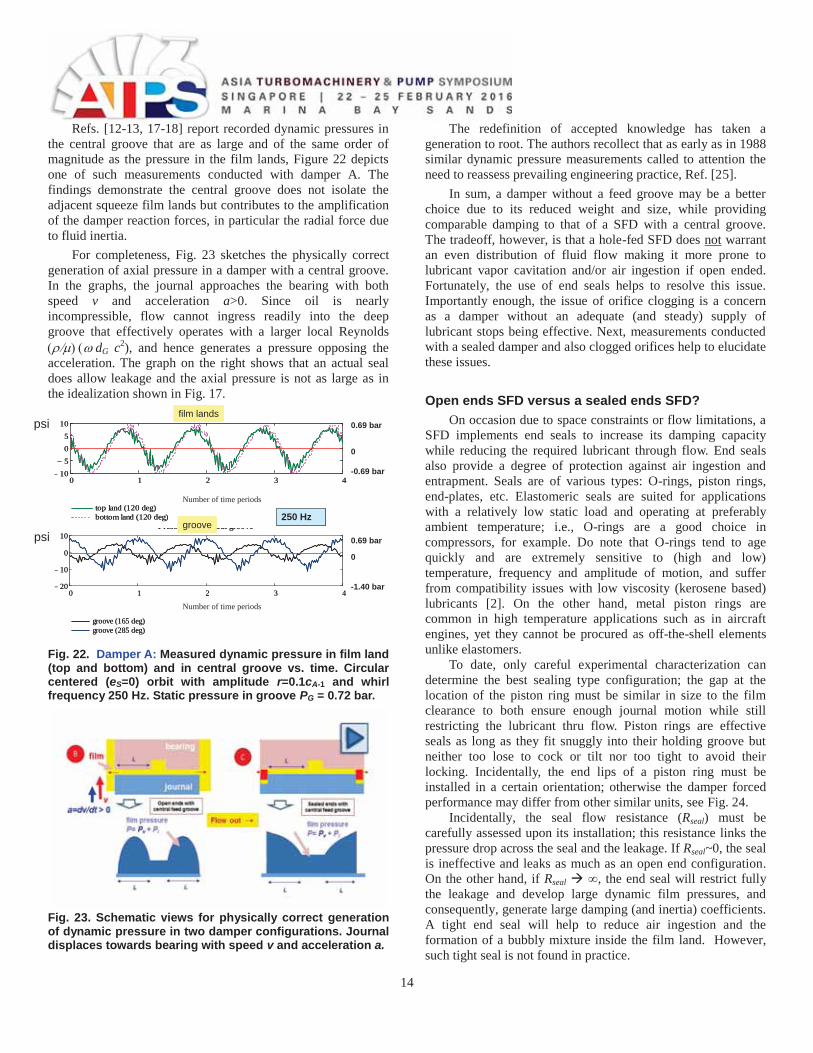
Refs. [12-13, 17-18] report recorded dynamic pressures in the central groove that are as large and of the same order of magnitude as the pressure in the film lands, Figure 22 depicts one of such measurements conducted with damper A. The findings demonstrate the central groove does not isolate the adjacent squeeze film lands but contributes to the amplification of the damper reaction forces, in particular the radial force due to fluid inertia.
For completeness, Fig. 23 sketches the physically correct generation of axial pressure in a damper with a central groove. In the graphs, the journal approaches the bearing with both speed v and acceleration a>0. Since oil is nearly incompressible, flow cannot ingress readily into the deep groove that effectively operates with a larger local Reynolds
dG c2), and hence generates a pressure opposing the acceleration. The graph on the right shows that an actual seal does allow leakage and the axial pressure is not as large as in the idealization shown in Fig. 17.
0 1 2 3 410
505
10
top land (120 deg)bottom land (120 deg)
time (-)
pres
sure
(psi)
0 1 2 3 420
10
0
10
groove (165 deg)groove (285 deg)
Pressures at central groove
time (-)
pres
sure
(psi)
250 Hz
Number of time periods
Number of time periods
psi
psi 0.69 bar
0
-0.69 bar
0.69 bar
0
-1.40 bar
film lands
groove
Fig. 22. Damper A: Measured dynamic pressure in film land (top and bottom) and in central groove vs. time. Circular centered (eS=0) orbit with amplitude r=0.1cA-1 and whirl frequency 250 Hz. Static pressure in groove PG = 0.72 bar.
Fig. 23. Schematic views for physically correct generation of dynamic pressure in two damper configurations. Journal displaces towards bearing with speed v and acceleration a.
The redefinition of accepted knowledge has taken a generation to root. The authors recollect that as early as in 1988 similar dynamic pressure measurements called to attention the need to reassess prevailing engineering practice, Ref. [25].
In sum, a damper without a feed groove may be a better choice due to its reduced weight and size, while providing comparable damping to that of a SFD with a central groove. The tradeoff, however, is that a hole-fed SFD does not warrant an even distribution of fluid flow making it more prone to lubricant vapor cavitation and/or air ingestion if open ended. Fortunately, the use of end seals helps to resolve this issue. Importantly enough, the issue of orifice clogging is a concern as a damper without an adequate (and steady) supply of lubricant stops being effective. Next, measurements conducted with a sealed damper and also clogged orifices help to elucidate these issues. Open ends SFD versus a sealed ends SFD?
On occasion due to space constraints or flow limitations, a SFD implements end seals to increase its damping capacity while reducing the required lubricant through flow. End seals also provide a degree of protection against air ingestion and entrapment. Seals are of various types: O-rings, piston rings, end-plates, etc. Elastomeric seals are suited for applications with a relatively low static load and operating at preferably ambient temperature; i.e., O-rings are a good choice in compressors, for example. Do note that O-rings tend to age quickly and are extremely sensitive to (high and low) temperature, frequency and amplitude of motion, and suffer from compatibility issues with low viscosity (kerosene based) lubricants [2]. On the other hand, metal piston rings are common in high temperature applications such as in aircraft engines, yet they cannot be procured as off-the-shell elements unlike elastomers.
To date, only careful experimental characterization can determine the best sealing type configuration; the gap at the location of the piston ring must be similar in size to the film clearance to both ensure enough journal motion while still restricting the lubricant thru flow. Piston rings are effective seals as long as they fit snuggly into their holding groove but neither too lose to cock or tilt nor too tight to avoid their locking. Incidentally, the end lips of a piston ring must be installed in a certain orientation; otherwise the damper forced performance may differ from other similar units, see Fig. 24.
Incidentally, the seal flow resistance (Rseal) must be carefully assessed upon its installation; this resistance links the pressure drop across the seal and the leakage. If Rseal~0, the seal is ineffective and leaks as much as an open end configuration. On the other hand, if Rseal ∞, the end seal will restrict fully the leakage and develop large dynamic film pressures, and consequently, generate large damping (and inertia) coefficients. A tight end seal will help to reduce air ingestion and the formation of a bubbly mixture inside the film land. However, such tight seal is not found in practice.
15
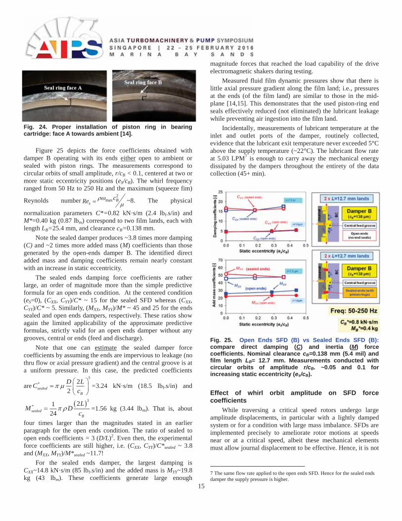
Fig. 24. Proper installation of piston ring in bearing cartridge: face A towards ambient [14].
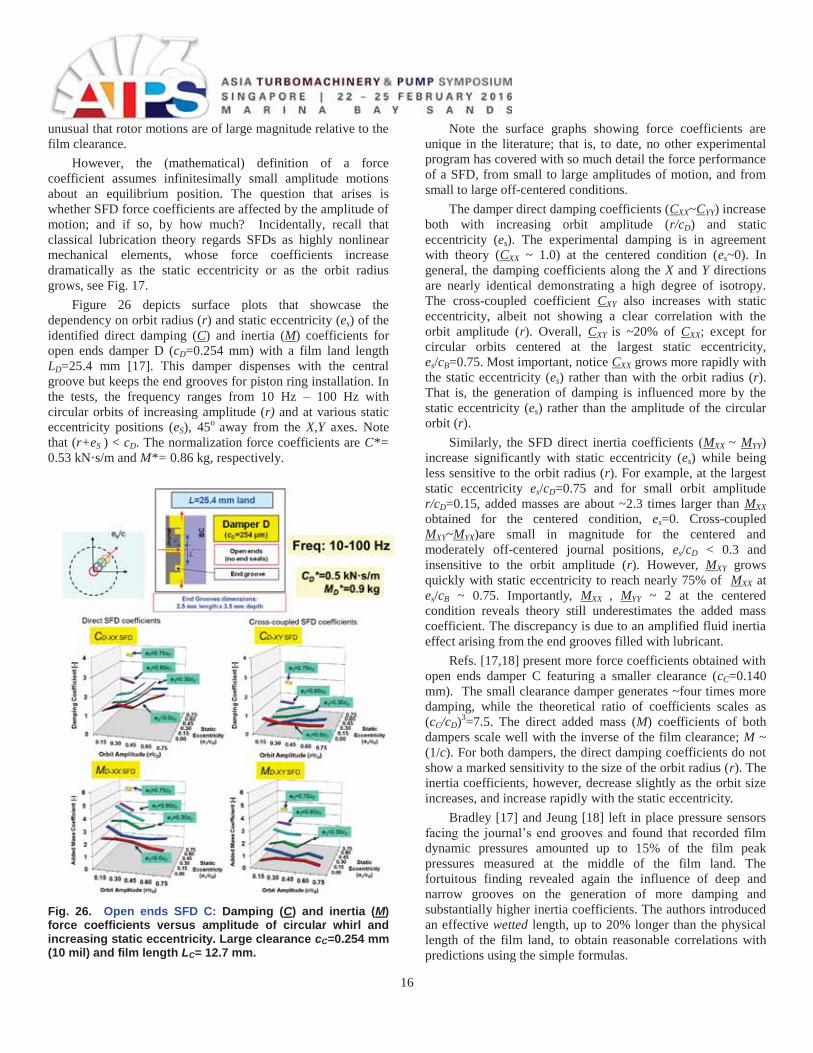
Figure 25 depicts the force coefficients obtained with damper B operating with its ends either open to ambient or sealed with piston rings. The measurements correspond to circular orbits of small amplitude, r/cB < 0.1, centered at two or more static eccentricity positions (eS/cB). The whirl frequency ranged from 50 Hz to 250 Hz and the maximum (squeeze fim)
Reynolds number2
max Bs
cRe ~8. The physical
normalization parameters C*=0.82 kN·s/m (2.4 lbf.s/in) and M*=0.40 kg (0.87 lbm) correspond to two film lands, each with length LB=25.4 mm, and clearance cB=0.138 mm.
Note the sealed damper produces ~3.8 times more damping (C) and ~2 times more added mass (M) coefficients than those generated by the open-ends damper B. The identified direct added mass and damping coefficients remain nearly constant with an increase in static eccentricity.
The sealed ends damping force coefficients are rather large, an order of magnitude more than the simple predictive formula for an open ends condition. At the centered condition (eS=0), (CXX, CYY)/C* ~ 15 for the sealed SFD whereas (CXX, CYY)/C* ~ 5. Similarly, (MXX, MYY)/M* ~ 45 and 25 for the ends sealed and open ends dampers, respectively. These ratios show again the limited applicability of the approximate predictive formulas, strictly valid for an open ends damper without any grooves, central or ends (feed and discharge).
Note that one can estimate the sealed damper force coefficients by assuming the ends are impervious to leakage (no thru flow or axial pressure gradient) and the central groove is at a uniform pressure. In this case, the predicted coefficients
are3
* 22sealed
B
D LCc
=3.24 kN·s/m (18.5 lbf.s/in) and
3* 21
24sealedB
LM D
c=1.56 kg (3.44 lbm). That is, about
four times larger than the magnitudes stated in an earlier paragraph for the open ends condition. The ratio of sealed to open ends coefficients = 3 (D/L)2. Even then, the experimental force coefficients are still higher, i.e. (CXX, CYY)/C*sealed ~ 3.8 and (MXX, MYY)/M*sealed ~11.7!
For the sealed ends damper, the largest damping is CXX~14.8 kN·s/m (85 lbf.s/in) and the added mass is MYY~19.8 kg (43 lbm). These coefficients generate large enough
magnitude forces that reached the load capability of the drive electromagnetic shakers during testing.
Measured fluid film dynamic pressures show that there is little axial pressure gradient along the film land; i.e., pressures at the ends (of the film land) are similar to those in the mid-plane [14,15]. This demonstrates that the used piston-ring end seals effectively reduced (not eliminated) the lubricant leakage while preventing air ingestion into the film land.
Incidentally, measurements of lubricant temperature at the inlet and outlet ports of the damper, routinely collected, evidence that the lubricant exit temperature never exceeded 5°C above the supply temperature (~22°C). The lubricant flow rate at 5.03 LPM7 is enough to carry away the mechanical energy dissipated by the dampers throughout the entirety of the data collection (45+ min).
Fig. 25. Open Ends SFD (B) vs Sealed Ends SFD (B): compare direct damping (C) and inertia (M) force coefficients. Nominal clearance cB=0.138 mm (5.4 mil) and film length LB= 12.7 mm. Measurements conducted with circular orbits of amplitude r/cB. ~0.05 and 0.1 for increasing static eccentricity (es/cB). Effect of whirl orbit amplitude on SFD force coefficients
While traversing a critical speed rotors undergo large amplitude displacements, in particular with a lightly damped system or for a condition with large mass imbalance. SFDs are implemented precisely to ameliorate rotor motions at speeds near or at a critical speed, albeit these mechanical elements must allow journal displacement to be effective. Hence, it is not
7 The same flow rate applied to the open ends SFD. Hence for the sealed ends damper the supply pressure is higher.
16
unusual that rotor motions are of large magnitude relative to the film clearance.
However, the (mathematical) definition of a force coefficient assumes infinitesimally small amplitude motions about an equilibrium position. The question that arises is whether SFD force coefficients are affected by the amplitude of motion; and if so, by how much? Incidentally, recall that classical lubrication theory regards SFDs as highly nonlinear mechanical elements, whose force coefficients increase dramatically as the static eccentricity or as the orbit radius grows, see Fig. 17.
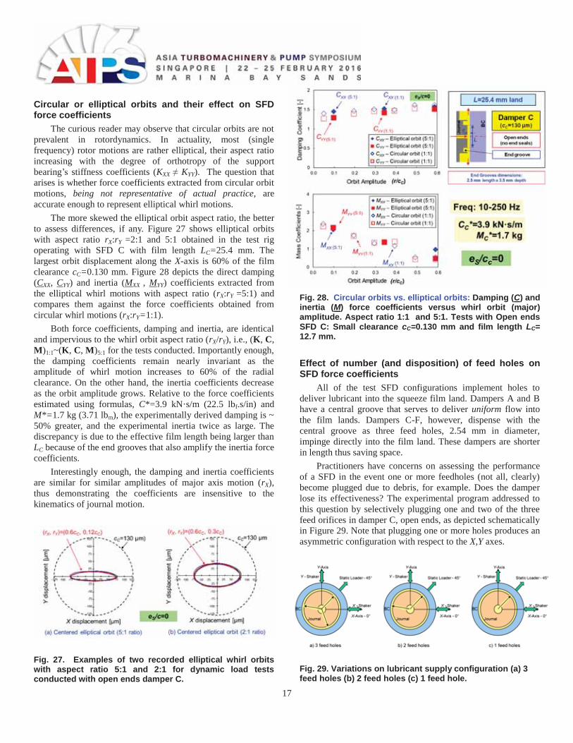
Figure 26 depicts surface plots that showcase the dependency on orbit radius (r) and static eccentricity (es) of the identified direct damping (C) and inertia (M) coefficients for open ends damper D (cD=0.254 mm) with a film land length LD=25.4 mm [17]. This damper dispenses with the central groove but keeps the end grooves for piston ring installation. In the tests, the frequency ranges from 10 Hz – 100 Hz with circular orbits of increasing amplitude (r) and at various static eccentricity positions (eS), 45o away from the X,Y axes. Note that (r+eS ) < cD. The normalization force coefficients are C*= 0.53 kN·s/m and M*= 0.86 kg, respectively.
Fig. 26. Open ends SFD C: Damping (C) and inertia (M) force coefficients versus amplitude of circular whirl and increasing static eccentricity. Large clearance cC=0.254 mm (10 mil) and film length LC= 12.7 mm.
Note the surface graphs showing force coefficients are unique in the literature; that is, to date, no other experimental program has covered with so much detail the force performance of a SFD, from small to large amplitudes of motion, and from small to large off-centered conditions.
The damper direct damping coefficients (CXX~CYY) increase both with increasing orbit amplitude (r/cD) and static eccentricity (es). The experimental damping is in agreement with theory (CXX ~ 1.0) at the centered condition (es~0). In general, the damping coefficients along the X and Y directions are nearly identical demonstrating a high degree of isotropy. The cross-coupled coefficient CXY also increases with static eccentricity, albeit not showing a clear correlation with the orbit amplitude (r). Overall, CXY is ~20% of CXX; except for circular orbits centered at the largest static eccentricity, es/cB=0.75. Most important, notice CXX grows more rapidly with the static eccentricity (es) rather than with the orbit radius (r). That is, the generation of damping is influenced more by the static eccentricity (es) rather than the amplitude of the circular orbit (r).
Similarly, the SFD direct inertia coefficients (MXX ~ MYY) increase significantly with static eccentricity (es) while being less sensitive to the orbit radius (r). For example, at the largest static eccentricity es/cD=0.75 and for small orbit amplitude r/cD=0.15, added masses are about ~2.3 times larger than MXX obtained for the centered condition, es=0. Cross-coupled MXY~MYX)are small in magnitude for the centered and moderately off-centered journal positions, es/cD < 0.3 and insensitive to the orbit amplitude (r). However, MXY grows quickly with static eccentricity to reach nearly 75% of MXX at es/cB ~ 0.75. Importantly, MXX , MYY ~ 2 at the centered condition reveals theory still underestimates the added mass coefficient. The discrepancy is due to an amplified fluid inertia effect arising from the end grooves filled with lubricant.
Refs. [17,18] present more force coefficients obtained with open ends damper C featuring a smaller clearance (cC=0.140 mm). The small clearance damper generates ~four times more damping, while the theoretical ratio of coefficients scales as (cC/cD)3=7.5. The direct added mass (M) coefficients of both dampers scale well with the inverse of the film clearance; M ~ (1/c). For both dampers, the direct damping coefficients do not show a marked sensitivity to the size of the orbit radius (r). The inertia coefficients, however, decrease slightly as the orbit size increases, and increase rapidly with the static eccentricity.
Bradley [17] and Jeung [18] left in place pressure sensors facing the journal’s end grooves and found that recorded film dynamic pressures amounted up to 15% of the film peak pressures measured at the middle of the film land. The fortuitous finding revealed again the influence of deep and narrow grooves on the generation of more damping and substantially higher inertia coefficients. The authors introduced an effective wetted length, up to 20% longer than the physical length of the film land, to obtain reasonable correlations with predictions using the simple formulas.
17
Circular or elliptical orbits and their effect on SFD force coefficients
The curious reader may observe that circular orbits are not prevalent in rotordynamics. In actuality, most (single frequency) rotor motions are rather elliptical, their aspect ratio increasing with the degree of orthotropy of the support bearing’s stiffness coefficients (KXX ≠ KYY). The question that arises is whether force coefficients extracted from circular orbit motions, being not representative of actual practice, are accurate enough to represent elliptical whirl motions.
The more skewed the elliptical orbit aspect ratio, the better to assess differences, if any. Figure 27 shows elliptical orbits with aspect ratio rX:rY =2:1 and 5:1 obtained in the test rig operating with SFD C with film length LC=25.4 mm. The largest orbit displacement along the X-axis is 60% of the film clearance cC=0.130 mm. Figure 28 depicts the direct damping (CXX, CYY) and inertia (MXX , MYY) coefficients extracted from the elliptical whirl motions with aspect ratio (rX:rY =5:1) and compares them against the force coefficients obtained from circular whirl motions (rX:rY=1:1).
Both force coefficients, damping and inertia, are identical and impervious to the whirl orbit aspect ratio (rX/rY), i.e., (K, C, M)1:1~(K, C, M)5:1 for the tests conducted. Importantly enough, the damping coefficients remain nearly invariant as the amplitude of whirl motion increases to 60% of the radial clearance. On the other hand, the inertia coefficients decrease as the orbit amplitude grows. Relative to the force coefficients estimated using formulas, C*=3.9 kN·s/m (22.5 lbf.s/in) and M*=1.7 kg (3.71 lbm), the experimentally derived damping is ~ 50% greater, and the experimental inertia twice as large. The discrepancy is due to the effective film length being larger than LC because of the end grooves that also amplify the inertia force coefficients.
Interestingly enough, the damping and inertia coefficients are similar for similar amplitudes of major axis motion (rX), thus demonstrating the coefficients are insensitive to the kinematics of journal motion.
Fig. 27. Examples of two recorded elliptical whirl orbits with aspect ratio 5:1 and 2:1 for dynamic load tests conducted with open ends damper C.
Fig. 28. Circular orbits vs. elliptical orbits: Damping (C) and inertia (M) force coefficients versus whirl orbit (major) amplitude. Aspect ratio 1:1 and 5:1. Tests with Open ends SFD C: Small clearance cC=0.130 mm and film length LC= 12.7 mm. Effect of number (and disposition) of feed holes on SFD force coefficients
All of the test SFD configurations implement holes to deliver lubricant into the squeeze film land. Dampers A and B have a central groove that serves to deliver uniform flow into the film lands. Dampers C-F, however, dispense with the central groove as three feed holes, 2.54 mm in diameter, impinge directly into the film land. These dampers are shorter in length thus saving space.
Practitioners have concerns on assessing the performance of a SFD in the event one or more feedholes (not all, clearly) become plugged due to debris, for example. Does the damper lose its effectiveness? The experimental program addressed to this question by selectively plugging one and two of the three feed orifices in damper C, open ends, as depicted schematically in Figure 29. Note that plugging one or more holes produces an asymmetric configuration with respect to the X,Y axes.
Fig. 29. Variations on lubricant supply configuration (a) 3 feed holes (b) 2 feed holes (c) 1 feed hole.
18
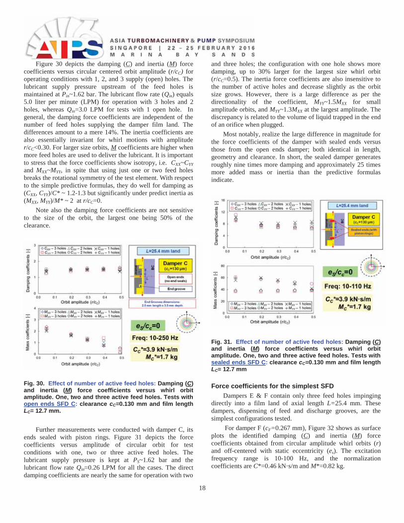
Figure 30 depicts the damping (C) and inertia (M) force coefficients versus circular centered orbit amplitude (r/cC) for operating conditions with 1, 2, and 3 supply (open) holes. The lubricant supply pressure upstream of the feed holes is maintained at Pin~1.62 bar. The lubricant flow rate (Qin) equals 5.0 liter per minute (LPM) for operation with 3 holes and 2 holes, whereas Qin=3.0 LPM for tests with 1 open hole. In general, the damping force coefficients are independent of the number of feed holes supplying the damper film land. The differences amount to a mere 14%. The inertia coefficients are also essentially invariant for whirl motions with amplitude r/cC<0.30. For larger size orbits, M coefficients are higher when more feed holes are used to deliver the lubricant. It is important to stress that the force coefficients show isotropy, i.e. CXX~CYY and MXX~MYY, in spite that using just one or two feed holes breaks the rotational symmetry of the test element. With respect to the simple predictive formulas, they do well for damping as (CXX, CYY)/C* ~ 1.2-1.3 but significantly under predict inertia as (MXX, MYY)/M* ~ 2 at r/cC=0.
Note also the damping force coefficients are not sensitive to the size of the orbit, the largest one being 50% of the clearance.
Fig. 30. Effect of number of active feed holes: Damping (C) and inertia (M) force coefficients versus whirl orbit amplitude. One, two and three active feed holes. Tests with open ends SFD C: clearance cC=0.130 mm and film length LC= 12.7 mm.
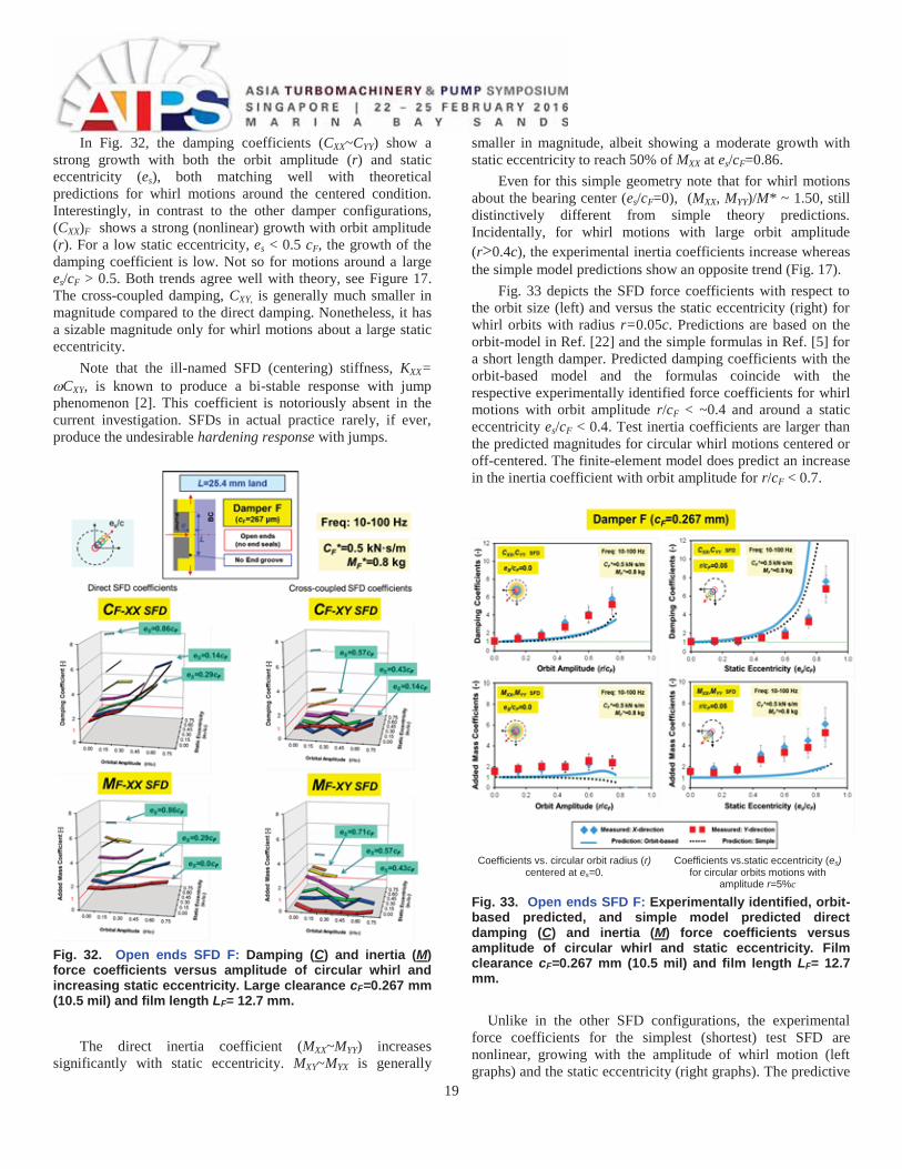
Further measurements were conducted with damper C, its ends sealed with piston rings. Figure 31 depicts the force coefficients versus amplitude of circular orbit for test conditions with one, two or three active feed holes. The lubricant supply pressure is kept at PS~1.62 bar and the lubricant flow rate Qin≈0.26 LPM for all the cases. The direct damping coefficients are nearly the same for operation with two
and three holes; the configuration with one hole shows more damping, up to 30% larger for the largest size whirl orbit (r/cC=0.5). The inertia force coefficients are also insensitive to the number of active holes and decrease slightly as the orbit size grows. However, there is a large difference as per the directionality of the coefficient, MYY~1.5MXX for small amplitude orbits, and MYY~1.3MXX at the largest amplitude. The discrepancy is related to the volume of liquid trapped in the end of an orifice when plugged.
Most notably, realize the large difference in magnitude for the force coefficients of the damper with sealed ends versus those from the open ends damper; both identical in length, geometry and clearance. In short, the sealed damper generates roughly nine times more damping and approximately 25 times more added mass or inertia than the predictive formulas indicate.
Fig. 31. Effect of number of active feed holes: Damping (C) and inertia (M) force coefficients versus whirl orbit amplitude. One, two and three active feed holes. Tests with sealed ends SFD C: clearance cC=0.130 mm and film length LC= 12.7 mm Force coefficients for the simplest SFD
Dampers E & F contain only three feed holes impinging directly into a film land of axial length L=25.4 mm. These dampers, dispensing of feed and discharge grooves, are the simplest configurations tested.
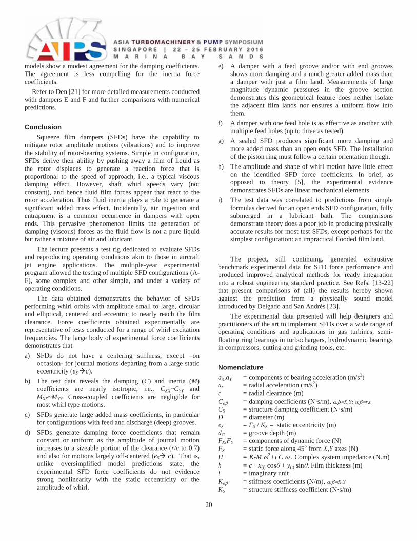
For damper F (cF=0.267 mm), Figure 32 shows as surface plots the identified damping (C) and inertia (M) force coefficients obtained from circular amplitude whirl orbits (r) and off-centered with static eccentricity (es). The excitation frequency range is 10-100 Hz, and the normalization coefficients are C*=0.46 kN·s/m and M*=0.82 kg.
19
In Fig. 32, the damping coefficients (CXX~CYY) show a strong growth with both the orbit amplitude (r) and static eccentricity (es), both matching well with theoretical predictions for whirl motions around the centered condition. Interestingly, in contrast to the other damper configurations, (CXX)F shows a strong (nonlinear) growth with orbit amplitude (r). For a low static eccentricity, es < 0.5 cF, the growth of the damping coefficient is low. Not so for motions around a large es/cF > 0.5. Both trends agree well with theory, see Figure 17. The cross-coupled damping, CXY, is generally much smaller in magnitude compared to the direct damping. Nonetheless, it has a sizable magnitude only for whirl motions about a large static eccentricity.
Note that the ill-named SFD (centering) stiffness, KXX= CXY, is known to produce a bi-stable response with jump
phenomenon [2]. This coefficient is notoriously absent in the current investigation. SFDs in actual practice rarely, if ever, produce the undesirable hardening response with jumps.
Fig. 32. Open ends SFD F: Damping (C) and inertia (M) force coefficients versus amplitude of circular whirl and increasing static eccentricity. Large clearance cF=0.267 mm (10.5 mil) and film length LF= 12.7 mm.
The direct inertia coefficient (MXX~MYY) increases significantly with static eccentricity. MXY~MYX is generally
smaller in magnitude, albeit showing a moderate growth with static eccentricity to reach 50% of MXX at es/cF=0.86.
Even for this simple geometry note that for whirl motions about the bearing center (es/cF=0), (MXX, MYY)/M* ~ 1.50, still distinctively different from simple theory predictions. Incidentally, for whirl motions with large orbit amplitude (r>0.4c), the experimental inertia coefficients increase whereas the simple model predictions show an opposite trend (Fig. 17).
Fig. 33 depicts the SFD force coefficients with respect to the orbit size (left) and versus the static eccentricity (right) for whirl orbits with radius r=0.05c. Predictions are based on the orbit-model in Ref. [22] and the simple formulas in Ref. [5] for a short length damper. Predicted damping coefficients with the orbit-based model and the formulas coincide with the respective experimentally identified force coefficients for whirl motions with orbit amplitude r/cF < ~0.4 and around a static eccentricity es/cF < 0.4. Test inertia coefficients are larger than the predicted magnitudes for circular whirl motions centered or off-centered. The finite-element model does predict an increase in the inertia coefficient with orbit amplitude for r/cF < 0.7.
Coefficients vs. circular orbit radius (r)
centered at es=0. Coefficients vs.static eccentricity (es)
for circular orbits motions with amplitude r=5%c
Fig. 33. Open ends SFD F: Experimentally identified, orbit-based predicted, and simple model predicted direct damping (C) and inertia (M) force coefficients versus amplitude of circular whirl and static eccentricity. Film clearance cF=0.267 mm (10.5 mil) and film length LF= 12.7 mm.
Unlike in the other SFD configurations, the experimental
force coefficients for the simplest (shortest) test SFD are nonlinear, growing with the amplitude of whirl motion (left graphs) and the static eccentricity (right graphs). The predictive
20
models show a modest agreement for the damping coefficients. The agreement is less compelling for the inertia force coefficients.
Refer to Den [21] for more detailed measurements conducted with dampers E and F and further comparisons with numerical predictions.
Conclusion Squeeze film dampers (SFDs) have the capability to
mitigate rotor amplitude motions (vibrations) and to improve the stability of rotor-bearing systems. Simple in configuration, SFDs derive their ability by pushing away a film of liquid as the rotor displaces to generate a reaction force that is proportional to the speed of approach, i.e., a typical viscous damping effect. However, shaft whirl speeds vary (not constant), and hence fluid film forces appear that react to the rotor acceleration. Thus fluid inertia plays a role to generate a significant added mass effect. Incidentally, air ingestion and entrapment is a common occurrence in dampers with open ends. This pervasive phenomenon limits the generation of damping (viscous) forces as the fluid flow is not a pure liquid but rather a mixture of air and lubricant.
The lecture presents a test rig dedicated to evaluate SFDs and reproducing operating conditions akin to those in aircraft jet engine applications. The multiple-year experimental program allowed the testing of multiple SFD configurations (A-F), some complex and other simple, and under a variety of operating conditions.
The data obtained demonstrates the behavior of SFDs performing whirl orbits with amplitude small to large, circular and elliptical, centered and eccentric to nearly reach the film clearance. Force coefficients obtained experimentally are representative of tests conducted for a range of whirl excitation frequencies. The large body of experimental force coefficients demonstrates that a) SFDs do not have a centering stiffness, except –on
occasion- for journal motions departing from a large static eccentricity (eS c).
b) The test data reveals the damping (C) and inertia (M) coefficients are nearly isotropic, i.e., CXX~CYY and MXX~MYY. Cross-coupled coefficients are negligible for most whirl type motions.
c) SFDs generate large added mass coefficients, in particular for configurations with feed and discharge (deep) grooves.
d) SFDs generate damping force coefficients that remain constant or uniform as the amplitude of journal motion increases to a sizeable portion of the clearance (r/c to 0.7) and also for motions largely off-centered (eS c). That is, unlike oversimplified model predictions state, the experimental SFD force coefficients do not evidence strong nonlinearity with the static eccentricity or the amplitude of whirl.
e) A damper with a feed groove and/or with end grooves shows more damping and a much greater added mass than a damper with just a film land. Measurements of large magnitude dynamic pressures in the groove section demonstrates this geometrical feature does neither isolate the adjacent film lands nor ensures a uniform flow into them.
f) A damper with one feed hole is as effective as another with multiple feed holes (up to three as tested).
g) A sealed SFD produces significant more damping and more added mass than an open ends SFD. The installation of the piston ring must follow a certain orientation though.
h) The amplitude and shape of whirl motion have little effect on the identified SFD force coefficients. In brief, as opposed to theory [5], the experimental evidence demonstrates SFDs are linear mechanical elements.
i) The test data was correlated to predictions from simple formulas derived for an open ends SFD configuration, fully submerged in a lubricant bath. The comparisons demonstrate theory does a poor job in producing physically accurate results for most test SFDs, except perhaps for the simplest configuration: an impractical flooded film land. The project, still continuing, generated exhaustive
benchmark experimental data for SFD force performance and produced improved analytical methods for ready integration into a robust engineering standard practice. See Refs. [13-22] that present comparisons of (all) the results hereby shown against the prediction from a physically sound model introduced by Delgado and San Andrés [23].
The experimental data presented will help designers and practitioners of the art to implement SFDs over a wide range of operating conditions and applications in gas turbines, semi-floating ring bearings in turbochargers, hydrodynamic bearings in compressors, cutting and grinding tools, etc. Nomenclature aX,aY = components of bearing acceleration (m/s2) ar = radial acceleration (m/s2) c = radial clearance (m) C = damping coefficients (N·s/m), X,Y; r,tCS = structure damping coefficient (N·s/m)D = diameter (m) eS = FS / KS = static eccentricity (m) dG = groove depth (m) FX,FY = components of dynamic force (N) FS = static force along 45o from X,Y axes (N) H = K-M 2+i C . Complex system impedance (N.m) h = c+ x(t) cos + y(t) sin . Film thickness (m) i = imaginary unit K = stiffness coefficients (N/m), X,YKS = structure stiffness coefficient (N·s/m)
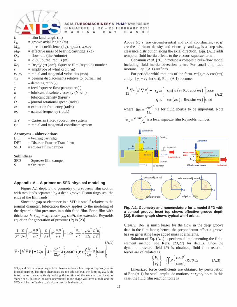
21
L = film land length (m) LG = groove axial length (m) M = inertia coefficients (kg), X,Y; r,tMBC = effective mass of bearing cartridge (kg) Qin = flow rate (liter/minute)R = ½ D. Journal radius (m) Res = Res= c2). Squeeze film Reynolds number. r = amplitude of whirl orbit (m) vr, , vt = radial and tangential velocities (m/s) x,y = bearing displacements relative to journal [m] ζ damping ratio (-)
feed /squeeze flow parameter (-) lubricant absolute viscosity (N·s/m) lubricant density (kg/m3) journal rotational speed (rad/s)
excitation frequency (rad/s) n natural frequency (rad/s)
X,Y = Cartesian (fixed) coordinate system r,t = radial and tangential coordinate system
Acronyms – abbreviations BC = bearing cartridge DFT = Discrete Fourier Transform SFD = squeeze film damper
Subindices SFD = Squeeze film damper S = Structure
Appendix A – A primer on SFD physical modeling Figure A.1 depicts the geometry of a squeeze film section
with two lands separated by a deep groove. Piston rings seal the ends of the film lands.
Since the gap or clearance in a SFD is small8 relative to the journal diameter, lubrication theory applies to the modeling of the dynamic film pressures in a thin fluid film. For a film with thickness h=(c(z) + x(t) cos + y(t) sin ), the extended Reynolds equation for generation of pressure (P) is [23]
2 23 3
2 21 12
12P P h h hh h
z z tR t
(A.1) 2 2
3 12 cos sin12 12
h hh P x x y y12122h h2h2
sinhh hh coscoscos hh hh coscoscoscoscoscoscos y yycoscoscoscoscoscos12 12
y y12 12
y y12 12
y y12 1212 1212 1212
h P3h P3h P3
8 Typical SFDs have a larger film clearance than a load support hydrodynamic journal bearing. Too tight clearances are not advisable as the damping available is too large, thus effectively locking the motion of the rotor at that location. Vance et al. [6] note the rotor operational mode shape will have a node and the SFD will be ineffective to dissipate mechanical energy.
Above ( , z) are circumferential and axial coordinates, ( ) are the lubricant density and viscosity, and c(z) is a step-wise clearance distribution along the axial direction. Eqn. (A.1) adds temporal fluid inertia effects to the viscous squeeze term. .
Gehannin et al. [26] introduce a complete bulk-flow model including fluid inertia advection terms. For small amplitude motions, Eqn. (A.1) suffices.
For periodic whirl motions of the form, x=[xo+ rX cos( t)] and y=[ yo + rY sin( t)], Eqn. (A.1) becomes
31 sin Re cos cos
12cos Re sin sin
hX
hY
h P r t t
r t t
h P3h P3h P3
(A.2)
where 2
Re12
hh >1 for fluid inertia to be important. Note
2Reh
h is a local squeeze film Reynolds number.
z
LLG
do
Bearing
Journal
End seal
c : clearance
Lubricant in
Lubricant out
orifice
groove
film land
dG
D, diameter
Lubricant in
recirculationzone
Effective groove depth
streamline
Lubricant out
separation line
d
Lubricant in
recirculationzone
Effective groove depth
streamline
Lubricant out
separation line
d
X
Y
X
Y
X
Y
elliptical orbitscircular orbits
centered journal off-centered journal
Fig. A.1. Geometry and nomenclature for a model SFD with a central groove. Inset top shows effective groove depth [22]. Bottom graph shows typical whirl orbits. Clearly, Reh is much larger for the flow in the deep groove than in the film lands; hence, the preponderant effect a groove has on generating large added mass coefficients.
Solution of Eq. (A.1) is performed implementing the finite element method; see Refs. [23,27] for details. Once the dynamic pressure field (P) is obtained, fluid film reaction forces are calculated as
cossin
X
Y
FP R d dz
F (A.3)
Linearized force coefficients are obtained by perturbation of Eqn (A.1) for small amplitude motions, r=rX=rY << c. In this case, the fluid film reaction force is
22
X X XX XY XX XY
Y Y YX YY YX YYo
F F C C M Mx xF F C C M My y
xM M XYM MXX XXX xXX XYXX XYXX XXXXX XYXX XYXX XY
M M yM MYX YYYX YYM MYX YYXM MM MM M
(A.4) where C X,Y and M X,Y are the damping and inertia coefficients, respectively.
Ref. [22] introduces a numerical method that replicates the experimental procedure to produce force coefficients valid for any type of whirl motion (large amplitude) and over a certain frequency range.
Refs. [13-22] present comparisons of test force coefficients against predictions from the physical model described by Eqn. (A.1). In all instances, the numerical model delivers force coefficients matching the experimental results. As per Ref. [23], a groove effective depth much lesser than the physical depth is recommended to predict accurately SFD force coefficients. The actual physical depth is of little consequence to the estimation of force coefficients. See inset in Fig A.1. In most cases, the effective depth is 2-4 times the clearance in the film lands.
The models in Refs. [22,23] bridge the gap between the experimental data in oil seal rings and SFDs and simple model predictions that ignore the flow field in grooved regions.
References [1] Zeidan, F. Y., Vance, J. M., and San Andrés, L., 1996
‘‘Design and Application of Squeeze Film Dampers in Rotating Machinery,’’ Proceedings of the 25th Turbomachinery Symposium, Texas A&M University, Houston, TX, pp. 169–188.
[2] San Andrés, L., 2012, “Squeeze Film Damper: Operation, Models and Technical Issues,” Modern Lubrication Theory, Notes 13, Texas A&M University, https://repository.tamu.edu/handle/1969.1/93197
[3] Della Pietra, L., and Adiletta, G., 2002, “The Squeeze Film Damper Over Four Decades of Investigations. Part I: Characteristics and Operating Features,” Shock Vib. Dig., 34(1), pp. 3–26.
[4] Adiletta, G., and Della Pietra, L., 2002, “The Squeeze Film Damper Over Four Decades of Investigations. Part II: Rotordynamics Analysis with Rigid and Flexible Rotors,” Shock Vib. Dig, 34(2), pp. 97–126.
[5] Vance, J., 1988, Rotordynamics of Turbomachinery, John Wiley and Sons, NY, Chapter 3.
[6] Vance, J., Zeidan, F., and Murphy, B., 2010, Machinery Vibration and Rotordynamics, John Wiley and Sons, NY, Chapter 5.
[7] Childs, D., 2013, Turbomachinery Rotordynamics with Case Studies, Minter Spring Pubs., TX, Chapter 6.
[8] San Andrés, L., 2012, “Static Load Performance of Plain Journal Bearings,” Modern Lubrication Theory, Notes 5, https://repository.tamu.edu/handle/1969.1/93197
[9] San Andrés, L., and Jeung, S.-H., 2015, “Response of an Squeeze Film Damper to Large Amplitude Impact Loads,” 2015 STLE Annual Meeting & Exhibition, May 18-21,
Dallas, TX, USA. [10] Zeidan, F. Y., and Vance, J. M., 1990, “Cavitation
Regimes in Squeeze Film Dampers and Their Effect on the Pressure Distribution,” STLE Trib. Trans., 33, pp.447-453.
[11] Diaz, S., and San Andrés, L., 1998, “Air Entrainment and Lubricant Vaporization in SFDs: An Assessment of their Fundamental Differences,” ASME J Gas Turb Pwr, 123, pp. 871-877.
[12] San Andrés, L., and Diaz, S., 2003, “Flow Visualization and Forces from a Squeeze Film Damper with Natural Air Entrainment,” ASME J. Tribol., 125, pp. 325-333.
[13] Seshaghiri, S., 2011, "Identification of Force Coefficients in Two Squeeze Film Dampers with a Central Groove," M.S. Thesis, Texas A&M University, May.
[14] Mahecha, P., 2011, "Experimental Dynamic Forced Performance of a Centrally Grooved, End Sealed Squeeze Film Damper," M.S. Thesis, Texas A&M University, August.
[15] San Andrés, L., 2012, “Damping and Inertia Coefficients for Two Open Ends Squeeze Film Dampers with a Central Groove: Measurements and Predictions,” ASME J Gas Turb Pwr, 134(10), p. 102506.
[16] San Andrés, L., and Seshagiri, S., 2013, “Damping and Inertia Coefficients for Two End Sealed Squeeze Film Dampers with a Central Groove: Measurements and Predictions,” ASME J Gas Turb Pwr, 135(12), p. 112503.
[16] San Andrés, L., 2014, “Force Coefficients for a Large Clearance Open Ends Squeeze Film Damper with a Central Groove: Experiments and Predictions,” Tribol. Int., 71, pp. 17-25.
[17] Bradley, G., 2013, “Performance of a Short Open-end Squeeze Film Damper with Feed Holes: Experimental Analysis of Dynamic Force Coefficients,” M.S. Thesis, Texas A&M University, August.
[18] Jeung, S.-H., 2013, “Performance of an Open Ends Squeeze Film Damper Operating with Large Amplitude Orbital Motions: Experimental Analysis and Assessment of the Accuracy of the Linearized Force Coefficients Model,” M.S. Thesis, Texas A&M University, December.
[19] San Andrés, L., and Jeung, S.-H., 2015, “Experimental Performance of an Open Ends, Centrally Grooved Squeeze Film Damper Operating with Large Amplitude Orbital Motions,” ASME J Gas Turb Pwr, 137(3), p. 032508.
[20] Jeung, S.-H., San Andrés, L., and Bradley, G., 2016, “Forced Coefficients for a Short Length, Open-Ends Squeeze Film Damper with End Grooves: Experiments and Predictions,” ASME J Gas Turb Pwr, 138(2), p. 022501.
[21] Den, S., 2015, “Analysis of Force Coefficients and Dynamic Pressures for Short-Length (L/D=0.2) Open-Ends Squeeze Film Dampers,” M.S. Thesis, Texas A&M University, December.
[22] San Andrés, L., and Jeung, S.-H., 2016, “Orbit-Model Force Coefficients for Fluid Film Bearings: A Step Beyond Linearization,” ASME J Gas Turb Pwr, 138(2), p. 022502.
[23] Delgado, A., and San Andrés, L., 2010, “A Model for
23
Improved Prediction of Force Coefficients in Grooved Squeeze Film Dampers and Grooved Oil Seal Rings”, ASME J. Tribol., 132, p. 032202.
[24] Reinhardt, F., and Lund, J. W., 1975, “The Influence of Fluid Inertia on the Dynamic Properties of Journal Bearings,” ASME J. Lubr. Technol., 97, pp. 154-167.
[25] San Andrés, L. and Vance, J., 1987, "Experimental Measurement of the Dynamic Pressure Distribution in a Squeeze-Film Bearing Damper Executing Circular Centered Orbits," ASLE Transactions, 30, pp. 373-383.
[26] Gehannin, J, Arghir, M., and Bonneau, O., 2009, “Complete Squeeze-Film Damper Analysis based on the “Bulk Flow” Equations,” Trib. Trans., 53, pp. 84-96.
[27] San Andrés, L., 2009, “Thermal Analysis of Finite Length Journal Bearings Including Fluid Inertia,” Modern Lubrication Theory, Notes 7, https://repository.tamu.edu/handle/1969.1/93197
Acknowledgments The continued substantial financial support of Pratt &
Whitney Engines is acknowledged. Thanks to Mr. Nagaraj Channasandra and Mr. Robert Morris at Pratt & Whitney for championing our research effort. The first author also thanks Mrs. Zeping Yu and Dr. Sachin Gogate at PW for their encouragement and useful suggestions.
The TAMU Turbomachinery Research Consortium also supported some of this work. Thanks to Mr. Ray Mathews for his assistance with laboratory safety and procedures.
The authors thank the participation of numerous students, graduate and undergraduate, all earning a first-class education while assisting to an intellectually stimulating project. Those former graduate students are Dr. Adolfo Delgado, the test rig designer and visionary, assisted by Shradda Sangelkar; Paola Mahecha and Sanjeev Seshaghiri working with dampers A and B; Gary Bradley and Sung-hwa Jeung produced quantum jumps with dampers C and D. Lastly, Sung-hwa and Sean Den mastered the test rig while pushing dampers E and F to their limits.
Thanks to the undergraduate students assisting the team: Sarabeth Froneberger, Logan Havel, James Law, Brian Butler, Jerry Haripin, Matthew Hilton, Ziam Gaznavi, Scott Tran, and Casey Yowell.
Thanks to Mr. Michael Rohmer for proof reading the manuscript and offering constructive criticism.