Embed Size (px)
Citation preview
SR-i500 FM 2-Way Security System
INSTALLATION MANUAL AND USER’S GUIDE
Standard Features • ½ mile 2-Way FM Transceiver • Remote sensor control • LCD Water proof / impact
resistant remote • Battery safeguard with “sleep
mode” • Ultra low power drain MCM • Violation display with time stamp • Built-in accelerometer • Passive arming • Ignition protection • Selectable arming / disarming • Range Confirmation Signal (RCS) • Programmable multi-tone siren
• Remote panic feature
Optional Accessories • Perimeter sensor (SN-5) – A miniature multi stage microwave sensor that detects motion
in mass around the motorcycle. • Ignition disable and anti-hijack kit (RID-5) - Allows remote disabling of the motorcycle’s
electrical system, should someone force you off your bike. Also prevents the engine from being started when the system is armed.
• Back-up battery (BAT-5) – A built-in back-up battery feature allowing the siren and transmitter to continue operating when power is interrupted.
• Factory Connector Kits–OEM style connectors that simply plug into the motorcycle’s factory wiring harness. Connector kits are available for select motorcycle models.
Table of Contents Installation
• Component List ---------------------------------------------------------------- Page 2 • Planning The Installation ---------------------------------------------------- Page 2 • Mounting The Components ----------------------------------------------- Page 3 • Color Codes --------------------------------------------------------------------- Page 3 • Connections --------------------------------------------------------------------- Page 4 • Using the T-tap Connectors ------------------------------------------------ Page 4
User’s Guide • Remote Transceiver Icons and Message Display ------------------- Page 5 • Turning Transceiver On / Off ----------------------------------------------- Page 5 • RCS (Range Conformation Signal) -------------------------------------- Page 6 • Transceiver Battery Status --------------------------------------------------- Page 6 • Operating Instructions ----- -------------------------------------------------- Page 6 • Alarm Triggers-------------------------------------------------------------------- Page 7 • Sensor Memory Display ------------------------------------------------------ Page 7 • Battery Safeguard with “Sleep Mode” -------------------------------- Page 7 • Motorcycle Battery Status -------------------------------------------------- Page 8 • Locking the Transceiver’s buttons --------------------------------------- Page 8 • Checking Motorcycle Status and Violation Display --------------- Page 8 • Programming and customizing Instructions -------------------------- Page 9 • Selecting Transceiver Alert Type ------------------------------------------ Page 9 • Selecting Auto / Manual Arming ----------------------------------------- Page 10 • Selecting Siren Tone and Alarm Duration ----------------------------- Page 10 • Adjusting the Accelerometer (Shock / Tilt ) Sensor ---------------- Page 10 • Setting Clock Time ------------------------------------------------------------ Page 11 • Setting Alarm Clock ---------------------------------------------------------- Page 11 • Encoding a Transceiver ------------------------------------------------------ Page 11
Optional Accessories Instructions • Perimeter Sensor (SN-5) ------------------------------------------------------ Page 12 • Ignition Disable / Anti-hijack Unit ----------------------------------------- Page 13 • Back-up Battery ---------------------------------------------------------------- Page 14
Warranty and FCC Information • Limited Warranty ------------------------------------------------------------- Page 15 • FCC Notice ---------------------------------------------------------------------- Page 15 • Contact information --------------------------------------------------------- Page 15
1
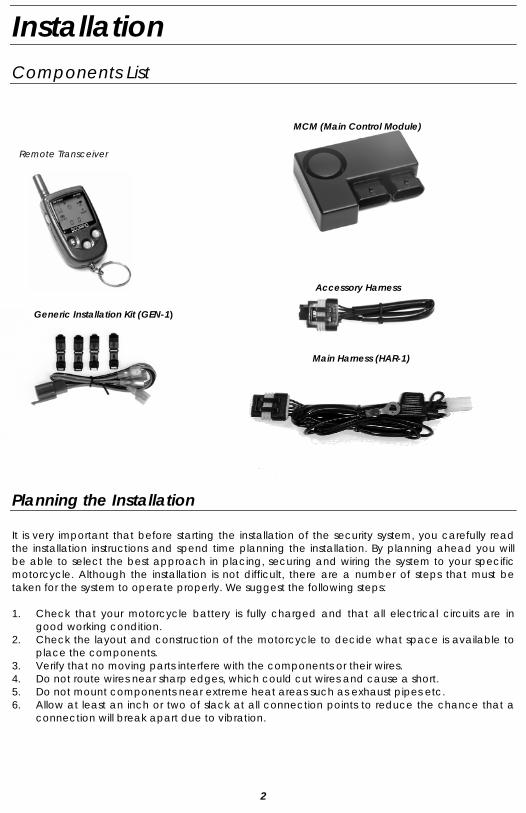
Installation Components List
MCM (Main Control Module)
Remote Transceiver
Accessory Harness Generic Installation Kit (GEN-1)
Main Harness (HAR-1)
Planning the Installation It is very important that before starting the installation of the security system, you carefully read the installation instructions and spend time planning the installation. By planning ahead you will be able to select the best approach in placing, securing and wiring the system to your specific motorcycle. Although the installation is not difficult, there are a number of steps that must be taken for the system to operate properly. We suggest the following steps: 1. Check that your motorcycle battery is fully charged and that all electrical circuits are in
good working condition. 2. Check the layout and construction of the motorcycle to decide what space is available to
place the components. 3. Verify that no moving parts interfere with the components or their wires. 4. Do not route wires near sharp edges, which could cut wires and cause a short. 5. Do not mount components near extreme heat areas such as exhaust pipes etc. 6. Allow at least an inch or two of slack at all connection points to reduce the chance that a
connection will break apart due to vibration.
2
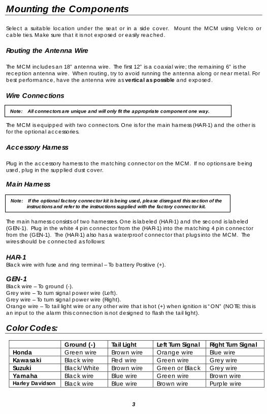
Mounting the Components Select a suitable location under the seat or in a side cover. Mount the MCM using Velcro or cable ties. Make sure that it is not exposed or easily reached.
Routing the Antenna Wire The MCM includes an 18” antenna wire. The first 12” is a coaxial wire; the remaining 6” is the reception antenna wire. When routing, try to avoid running the antenna along or near metal. For best performance, have the antenna wire as vertical as possible and exposed.
Wire Connections
Note: All connectors are unique and will only fit the appropriate component one way. The MCM is equipped with two connectors. One is for the main harness (HAR-1) and the other is for the optional accessories.
Accessory Harness Plug in the accessory harness to the matching connector on the MCM. If no options are being used, plug in the supplied dust cover. Main Harness Note: If the optional factory connector kit is being used, please disregard this section of the
instructions and refer to the instructions supplied with the factory connector kit. The main harness consists of two harnesses. One is labeled (HAR-1) and the second is labeled (GEN-1). Plug in the white 4 pin connector from the (HAR-1) into the matching 4 pin connector from the (GEN-1). The (HAR-1) also has a waterproof connector that plugs into the MCM. The wires should be connected as follows: HAR-1 Black wire with fuse and ring terminal – To battery Positive (+). GEN-1 Black wire – To ground (-). Grey wire – To turn signal power wire (Left). Grey wire – To turn signal power wire (Right). Orange wire – To tail light wire or any other wire that is hot (+) when ignition is “ON” (NOTE: this is an input to the alarm this connection is not designed to flash the tail light).
Color Codes:
Ground (-) Tail Light Left Turn Signal Right Turn Signal Honda Green wire Brown wire Orange wire Blue wire Kawasaki Black wire Red wire Green wire Grey wire Suzuki Black/White Brown wire Green or Black Grey wire Yamaha Black wire Blue wire Green wire Brown wire Harley Davidson Black wire Blue wire Brown wire Purple wire
3
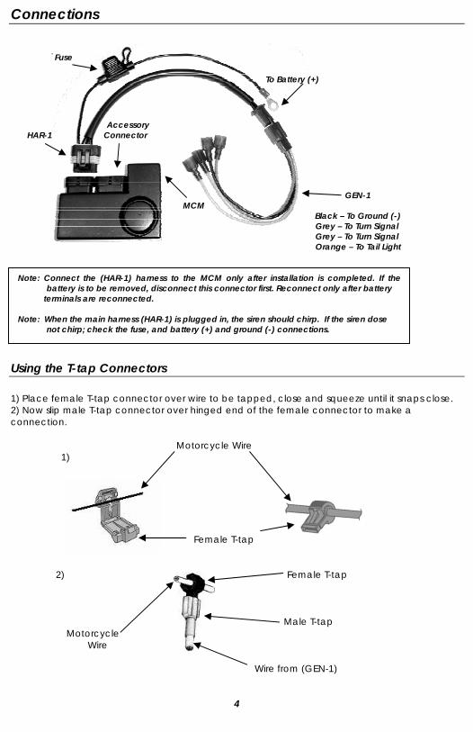
Connections
Fuse To Battery (+) Accessory HAR-1 Connector GEN-1
MCM Black – To Ground (-) Grey – To Turn Signal Grey – To Turn Signal Orange – To Tail Light
Note: Connect the (HAR-1) harness to the MCM only after installation is completed. If the battery is to be removed, disconnect this connector first. Reconnect only after battery
terminals are reconnected. Note: When the main harness (HAR-1) is plugged in, the siren should chirp. If the siren dose
not chirp; check the fuse, and battery (+) and ground (-) connections.
Using the T-tap Connectors 1) Place female T-tap connector over wire to be tapped, close and squeeze until it snaps close. 2) Now slip male T-tap connector over hinged end of the female connector to make a connection. Motorcycle Wire 1) Female T-tap 2) Female T-tap Male T-tap Motorcycle Wire
Wire from (GEN-1)
4
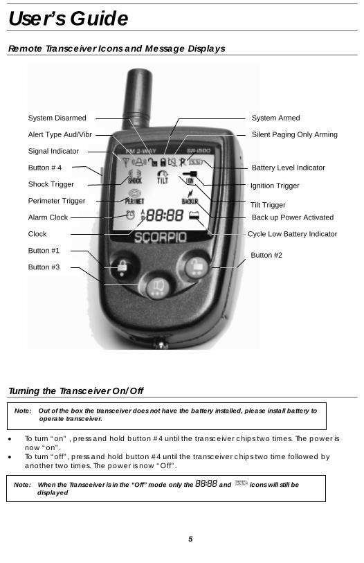
User’s Guide Remote Transceiver Icons and Message Displays
3. Press button 4 repeatedly to scroll though the programmable icons
Battery Level Indicator
System Armed
Silent Paging Only Arming
Shock Trigger
Perimeter Trigger
Alarm Clock
Ignition Trigger
Clock
Back up Power Activated
Signal Indicator
Alert Type Aud/Vibr
System Disarmed
Tilt Trigger
Button #1 Button #2 Button #3
Button # 4
Cycle Low Battery Indicator
Turning the Transceiver On/Off • To turn “on” , press and hold button #4 until the transceiver chips two times. The power is
now “on”. • To turn “off”, press and hold button #4 until the transceiver chips two time followed by
another two times. The power is now “Off”.
Note: When the Transceiver is in the “Off” mode only the and icons will still be displayed
Note: Out of the box the transceiver does not have the battery installed, please install battery to operate transceiver.
5
RCS (Range Confirmation Signal)
If the system is armed and the Transceiver is within range of the MCM the LCD displays icon If the Transceiver does not receive the RCS signal the icon will not appear.
Transceiver Battery Status The LCD will display 3 different icons to show the Transceiver battery status.
Operating Instructions The following instruction assumes that the transceiver is with in range of the motorcycle. Arm
1. Press button #1, siren chirps 3 times and the turn signal lights flash 1 time.
2. The Transceiver echoes 3 chirps and the LCD displays and and PERIMT OFF icons. Disarm
1. Press button #2, siren chirps 1 time and lights flash 1 time. 2. The Transceiver echoes 1 chirp and the LCD displays icon.
Arming With Optional Perimeter Sensor 1. Press button #3, siren chirps 4 times and turn signal lights flash 1 time.
2. The Transceiver echoes 4 chirps and the LCD displays , icons. 3. The system is armed and the Perimeter Sensor is activated.
Arming Without Siren / Paging Only 1. Press buttons #1 and #3 at the same time, siren chirps 5 times and the turn signal lights
flash 1 time.
2. The Transceiver echoes 5 chirps and the LCD displays , and icons. 3. The system is armed but the siren and turn signal lights are disabled for a silent paging
only alert. Arming Without Siren or Perimeter Sensor (optional) / Paging Only
1. Press buttons #2 and #3 at the same time, siren chirps 6 times and the turn signal lights flash 1 time.
2. The Transceiver echoes 6 chirps and the LCD displays , , and PERIMT OFF icons. 3. The system is armed but the siren, turn signal lights and perimeter sensor are disabled.
Panic/ Stop Trigger a. When system is armed press button #3 for Panic feature. (panic feature will sound siren for a few seconds, drawing attention to your bike) b. Pressing button #3 during an alarm trigger stops the alarm cycle but keeps the system armed.
6
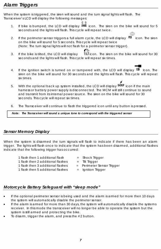
Alarm Triggers When the system is triggered, the siren will sound and the turn signal lights will flash. The Transceiver’s LCD will display the following messages:
1. If bike is bumped, the LCD will display icon. The siren on the bike will sound for 5 seconds and the lights will flash. This cycle will repeat twice.
2. If the perimeter sensor triggers a full alarm cycle, the LCD will display icon. The siren
on the bike will sound for 5 seconds. This cycle will repeat twice (Note: The turn signal lights will not flash for a perimeter sensor trigger).
3. If the bike is tilted, the LCD will display icon. The siren on the bike will sound for 30
seconds and the lights will flash. This cycle will repeat six times.
4. If the ignition switch is turned on or tampered with, the LCD will display Icon. The siren on the bike will sound for 30 seconds and the lights will flash. This cycle will repeat six times.
5. With the optional back up system installed, the LCD will display icon if the main
harness or battery power supply is disconnected. The MCM will still continue to sound and transmit from its internal power source. The siren on the bike will sound for 30 seconds. This cycle will repeat six times.
6. The Transceiver will continue to flash the triggered icon until any button is pressed.
Note: The Transceiver will sound a unique tone to correspond with the triggered sensor
Sensor Memory Display When the system is disarmed the turn signals will flash to indicate if there has been an alarm trigger. The lights will flash once to indicate that the system has been disarmed, additional flashes indicate that the following trigger has occurred:
1 flash then 1 additional flash = Shock Trigger 1 flash then 2 additional flashes = Tilt Trigger 1 flash then 3 additional flashes = Perimeter Sensor Trigger 1 flash then 5 additional flashes = Ignition Trigger
Motorcycle Battery Safeguard with “sleep mode” • If the optional perimeter sensor is being used and the alarm is armed for more then 10 days
the system will automatically disable the perimeter sensor. • If the alarm is armed for more than 30 days, the system will automatically disable the systems
receiver. In this mode the transceiver will no longer be able to operate the system but the system is still armed and protecting the bike.
• To disarm, trigger the alarm, and press the #2 button.
7
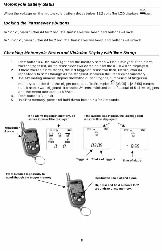
Motorcycle Battery Status When the voltage on the motorcycle battery drops below 11.2 volts The LCD displays icon. Locking the Transceiver’s buttons To “lock”, press button #4 for 2 sec. The Transceiver will beep and buttons will lock. To “unlock”, press button #4 for 2 sec. The Transceiver will beep and buttons will unlock.
Checking Motorcycle Status and Violation Display with Time Stamp
1. Press button #4. The back light and the memory screen will be displayed. If the alarm was not triggered, all the sensor icons will come on and the # 0 0 will be displayed.
2. If there was an alarm trigger, the last triggered sensor will flash. Press button #4 repeatedly to scroll through all the triggered sensors in the Transceiver’s memory.
3. The alternating numeric display shows the current trigger, numbering of triggers in
memory, and the time the trigger occurred. For Example: [03 05] + [A 8:55] means the tilt sensor was triggered. It was the 3rd sensor violated out of a total of 5 alarm triggers and the event occurred at 8:55am.
4. Press button #3 to exit. 5. To clear memory, press and hold down button #3 for 2 seconds.
If no alarm triggers in memory, all sensor icons will be displayed
If the system was trigged, the last triggered sensor will be displayed
Press button 4 once
Time of trigger Trigger # Total # of triggers
Press button 4 repeatedly to scroll though the trigger memory Pres button 3 to exit and clear.
Or, press and hold button 3 for 2 seconds to erase memory.
8
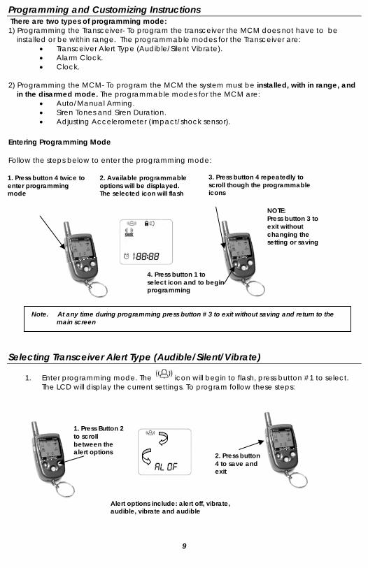
Programming and Customizing Instructions There are two types of programming mode: 1) Programming the Transceiver- To program the transceiver the MCM does not have to be
installed or be within range. The programmable modes for the Transceiver are: • Transceiver Alert Type (Audible/Silent Vibrate). • Alarm Clock. • Clock.
2) Programming the MCM- To program the MCM the system must be installed, with in range, and
in the disarmed mode. The programmable modes for the MCM are: • Auto/Manual Arming. • Siren Tones and Siren Duration. • Adjusting Accelerometer (impact/shock sensor).
Entering Programming Mode Follow the steps below to enter the programming mode:
3. Press button 4 repeatedly to scroll though the programmable icons
NOTE: Press button 3 to exit without changing the setting or saving
4. Press button 1 toselect icon and to beginprogramming
1. Press button 4 twice to enter programming mode
2. Available programmable options will be displayed. The selected icon will flash
4. Press button 1 to select icon and to begin programming
1. Press Button 2 to scroll between the alert options
Alert options include: alert off, vibrate, audible, vibrate and audible
Selecting Transceiver Alert Type (Audible/Silent/Vibrate)
1. Enter programming mode. The icon will begin to flash, press button #1 to select. The LCD will display the current settings. To program follow these steps:
Note. At any time during programming press button # 3 to exit without saving and return to the main screen
2. Press button 4 to save and exit
9
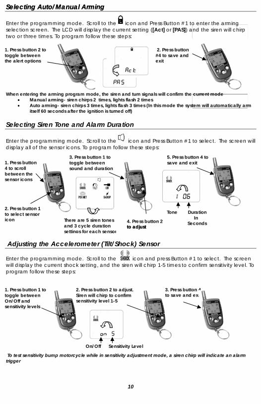
Selecting Auto/Manual Arming Selecting Auto/Manual Arming Enter the programming mode. Scroll to the icon and Press Button #1 to enter the arming selection screen. The LCD will display the current setting ([Act] or [PAS]) and the siren will chirp two or three times. To program follow these steps:
2. Press button #4 to save and exit
1. Press button 2 to toggle between the alert options
When entering the arming program mode, the siren and turn signals will confirm the current mode
• Manual arming- siren chirps 2 times, lights flash 2 times • Auto arming- siren chirps 3 times, lights flash 3 times (In this mode the system will automatically arm
itself 60 seconds after the ignition is turned off) Selecting Siren Tone and Alarm Duration Enter the programming mode. Scroll to the icon and Press Button #1 to select. The screen will display all of the sensor icons. To program follow these steps:
1. Press button 4 to scroll between the sensor icons
3. Press button 1 to toggle between sound and duration
5. Press button 4 to save and exit
Tone Duration In Seconds
.
4. Press button 2 to adjust to adjust
Adjusting the Accelerometer (Tilt/Shock) Sensor Enter the programming mode. Scroll to the icon and press Button #1 to select. The screen will display the current shock setting, and the siren will chirp 1-5 times to confirm sensitivity level. To program follow these steps:
2. Press button 2 to adjust. Siren will chirp to confirm sensitivity level 1-5
1. Press button 1 to toggle between On/Off and sensitivity levels
3. Press button 4 to save and exit
On/Off Sensitivity Level
2. Press button 1 to select sensor icon There are 5 siren tones
and 3 cycle duration settings for each sensor
To test sensitivity bump motorcycle while in sensitivity adjustment mode, a siren chirp will indicate an alarm trigger
10
Setting Clock Time
1. Enter the programming mode. 2. Press button #4 repeatedly until the icon begins to flash. 3. Press button #1 to select and enter clock setting mode. 4. Press button #1 to scroll through ‘hour’, ‘minute’, ‘am/pm’ settings. The selected item
will be flashing. 5. Press button #2 to adjust the setting of the selected item. 6. Press button #4 to save setting and exit, or press button #3 to abort.
Setting Alarm Clock
1. Enter the programming mode.
2. Press button #4 repeatedly until icon begins to flash. 3. Press button #1 to select and enter alarm clock setting mode 4. Press button #1 to scroll through ‘alarm on/off’, ‘hour’, ‘minute’, ‘am/pm’ settings. The
selected item will be flashing. 5. Press button #2 to adjust the setting of the selected item. 6. Press button #4 to save setting and exit, or press button #3 to abort.
Encoding a Transceiver
Note: Transceivers are programmed from the factory. Encoding is only necessary should the Transceiver loses its codes and will not arm or disarm the security system or if a second or replacement remote is obtained.
1. Unplug HAR-1 from the MCM and plug it back in, the siren will chirp 2 times and the lights
will flash 2 times. 2. Within 6 seconds turn ignition switch “ON” and “OFF” 3 times. 3. If step 3 is done correctly and within the time allowed , the siren will chirp 2 times and
the lights will flash an additional 2 times to confirm that the system is in “Learn Mode”. 4. Press and hold button # 1 until the system chirps 2 times and the lights flash 2 times to
indicate that the MCM has learned the code. 5. The Transceiver echoes 4 chirps and the LCD displays [LErn donE] to confirm that the
Transceiver is encoded. 6. Turn ignition “ON” and “OFF” to exit “Learn Mode”.
This Section purposely left blank
11
Optional Accessories
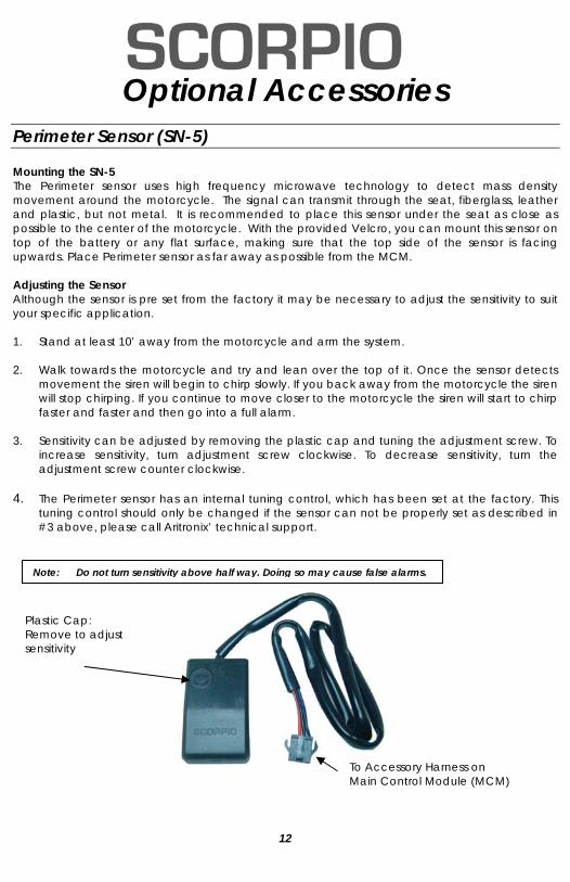
Perimeter Sensor (SN-5) Mounting the SN-5 The Perimeter sensor uses high frequency microwave technology to detect mass density movement around the motorcycle. The signal can transmit through the seat, fiberglass, leather and plastic, but not metal. It is recommended to place this sensor under the seat as close as possible to the center of the motorcycle. With the provided Velcro, you can mount this sensor on top of the battery or any flat surface, making sure that the top side of the sensor is facing upwards. Place Perimeter sensor as far away as possible from the MCM. Adjusting the Sensor Although the sensor is pre set from the factory it may be necessary to adjust the sensitivity to suit your specific application. 1. Stand at least 10’ away from the motorcycle and arm the system. 2. Walk towards the motorcycle and try and lean over the top of it. Once the sensor detects
movement the siren will begin to chirp slowly. If you back away from the motorcycle the siren will stop chirping. If you continue to move closer to the motorcycle the siren will start to chirp faster and faster and then go into a full alarm.
3. Sensitivity can be adjusted by removing the plastic cap and tuning the adjustment screw. To
increase sensitivity, turn adjustment screw clockwise. To decrease sensitivity, turn the adjustment screw counter clockwise.
4. The Perimeter sensor has an internal tuning control, which has been set at the factory. This
tuning control should only be changed if the sensor can not be properly set as described in #3 above, please call Aritronix’ technical support.
Plastic Cap: Remove to adjust sensitivity
To Accessory Harness on Main Control Module (MCM)
Note: Do not turn sensitivity above half way. Doing so may cause false alarms.
12
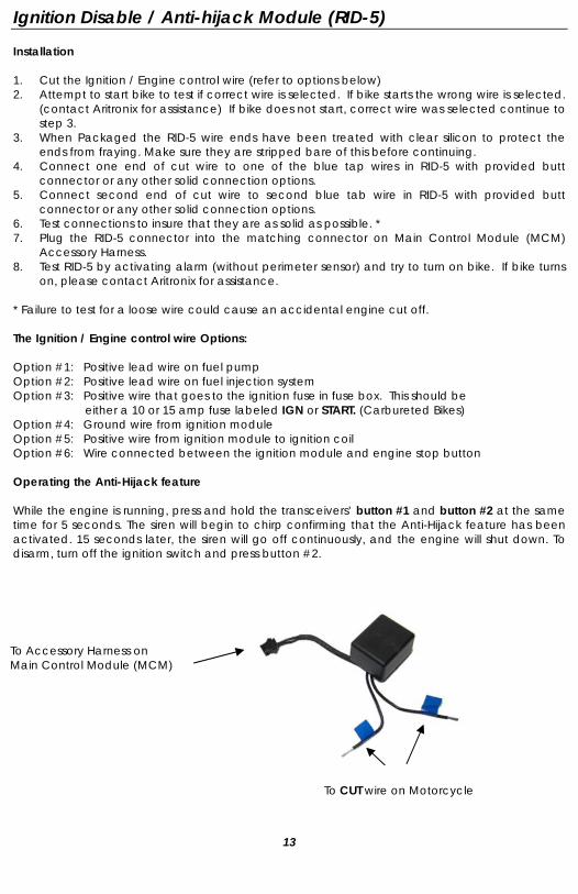
Ignition Disable / Anti-hijack Module (RID-5) Installation 1. Cut the Ignition / Engine control wire (refer to options below) 2. Attempt to start bike to test if correct wire is selected. If bike starts the wrong wire is selected.
(contact Aritronix for assistance) If bike does not start, correct wire was selected continue to step 3.
3. When Packaged the RID-5 wire ends have been treated with clear silicon to protect the ends from fraying. Make sure they are stripped bare of this before continuing.
4. Connect one end of cut wire to one of the blue tap wires in RID-5 with provided butt connector or any other solid connection options.
5. Connect second end of cut wire to second blue tab wire in RID-5 with provided butt connector or any other solid connection options.
6. Test connections to insure that they are as solid as possible. * 7. Plug the RID-5 connector into the matching connector on Main Control Module (MCM)
Accessory Harness. 8. Test RID-5 by activating alarm (without perimeter sensor) and try to turn on bike. If bike turns
on, please contact Aritronix for assistance. * Failure to test for a loose wire could cause an accidental engine cut off. The Ignition / Engine control wire Options: Option #1: Positive lead wire on fuel pump Option #2: Positive lead wire on fuel injection system Option #3: Positive wire that goes to the ignition fuse in fuse box. This should be
either a 10 or 15 amp fuse labeled IGN or START. (Carbureted Bikes) Option #4: Ground wire from ignition module Option #5: Positive wire from ignition module to ignition coil Option #6: Wire connected between the ignition module and engine stop button Operating the Anti-Hijack feature While the engine is running, press and hold the transceivers’ button #1 and button #2 at the same time for 5 seconds. The siren will begin to chirp confirming that the Anti-Hijack feature has been activated. 15 seconds later, the siren will go off continuously, and the engine will shut down. To disarm, turn off the ignition switch and press button #2.
To Accessory Harness on Main Control Module (MCM)
To CUT wire on Motorcycle
13
Back-up Battery (BAT-5) The back-up battery provides the system the ability to transmit information and activate the siren when power is interrupted. If power is ever interrupted while the system is activated the back-up battery will be engaged, the transceiver will receive a full alarm and the siren will sound in 25 second increments. If power is not restored the alarm will continue to transmit and sound for six cycles.
Note: The system has to be correctly installed for at least 12 hours before full function of the back-up battery can be used.
To check the status of the back-up battery active the system using button #1.
• If the Alarm chirps 3 times the back-up battery is in good working condition • If the system chirps 2 times the back-up battery is not fully charge.
Note: If the system chirps only 2 times and it has been correctly connected for more the 12
hours the battery needs replacement. (Contact Aritronix for replacement options)
This Section purposely left blank
14

What should you do if you experience a problem with a Scorpio product? First contact Aritronix, Ltd. using one of the methods listed below. [Proof of purchase, installer and motorcycle information will be requested]. If after assistance from our trained staff it is determined that the Scorpio product may be faulty then you will provide with detailed information on processing a warranty claim. All warranty claims must contain a return authorization number (RA#). Aritronix, Ltd. will not accept any package that does not have been approved for warranty repair/exchange.
Shipping and Handling If a warranty claim is requested and approved a standard shipping and handling charge will apply. All charges have to be paid before package is returned back to customer.
What is not covered by this limited warranty? This limited warranty does not cover cosmetic damage, damage/failure due to acts of God: Problems that result from:
• External causes such as accident, abuse, misuse, or problems with electrical power. • Usage that is not in accordance with product instructions or modifications of the
product. • Failure to follow the product instructions. • Problems caused by using accessories, parts, or components not manufactured or
approved by Scorpio.
What is covered by this limited warranty? This limited warranty covers defects in materials and workmanship in your — our end-user customer's — Scorpio-branded hardware products, including Scorpio-branded accessory products.
Limited Warranty Scorpio-branded security products come with a 2-year (from time of purchase) limited warranty. This includes all components and accessories that are manufactured by Aritronix Ltd. The following sections describe the limited warranties.
For technical assistance with any of the procedures on this manual, or for warranty claims please contact Aritronix at:
www.scorpioalarms.com [email protected]
Toll Free International
(800)428-0440 (480)951-1109
Aritronix Ltd 16055 N. Dial Blvd. B-10
Scottsdale, AZ 85260
Changes or modifications not expressly approved by the party responsible for compliance could void the user’s authority to operate this device.
This device complies with Part 15 of FCC rules. Operation is subject to the following two conditions: (1) This device may not cause harmful interference, and (2) This device must accept any interference that may cause undesired operation.
FCC Notice


![536 0 2-2 02litstore.phdinc.com/pdf.asp?filename=SWITCH.pdf · LETTER DIM. 63549-02 63549-05 PIN 2/4 WIRE COLOR BLACK PIN 1 WIRE COLOR BROWN PIN 3 WIRE COLOR BLUE A ˜ .402 [10.2].689](https://img.pdfslide.net/doc/110x75/5fac6cbda3f398026c379947/536-0-2-2-letter-dim-63549-02-63549-05-pin-24-wire-color-black-pin-1-wire-color.jpg)