Embed Size (px)
Citation preview
Honeywell Process Solutions
ST 800 & ST 700 SmartLine Transmitter
HART® Communications Options Safety Manual
34-ST-25-37
Revision 6.0
December 2016
ii ST 800 & ST 700 Safety Manual December 2016
Copyrights, Notices and Trademarks
© Copyright 2016 by Honeywell, Inc.
Revision 6.0, December 2016
While the information in this document is presented in good faith and believed to be accurate,
Honeywell disclaims any implied warranties of merchantability and fitness for a particular
purpose and makes no express warranties except as may be stated in the written agreement with
and for its customers. In no event is Honeywell liable to anyone for any indirect, special, or
consequential damages. The information and specifications in this document are subject to
change without notice.
Honeywell, SFC and SmartLine, are registered trademarks of Honeywell International Inc.
Other brand or product names are trademarks of their respective owners.
Honeywell Process Solutions
1250 W Sam Houston Pkwy S
Houston, TX 77042
December 2016 ST 800 & ST 700 Safety Manual iii
About This Document
Release Information
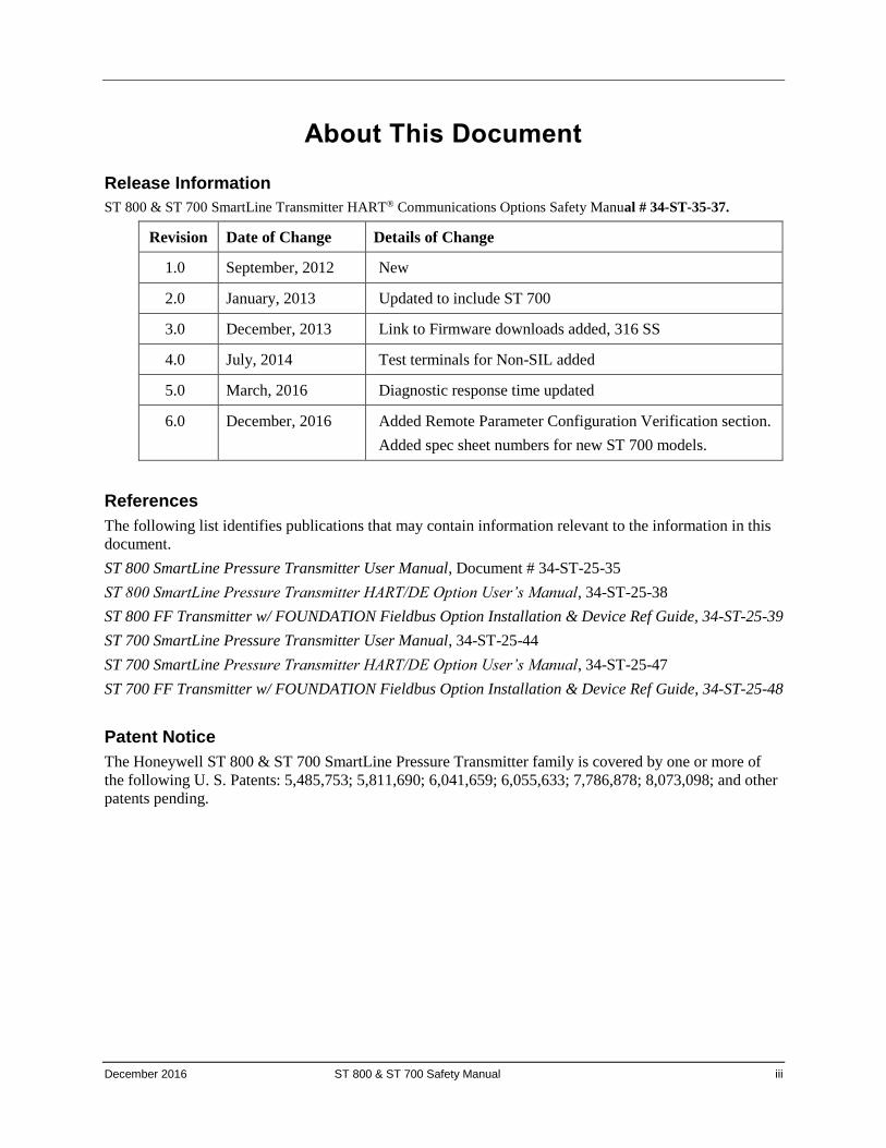
ST 800 & ST 700 SmartLine Transmitter HART® Communications Options Safety Manual # 34-ST-35-37. Revision Date of Change Details of Change
1.0 September, 2012 New
2.0 January, 2013 Updated to include ST 700
3.0 December, 2013 Link to Firmware downloads added, 316 SS
4.0 July, 2014 Test terminals for Non-SIL added
5.0 March, 2016 Diagnostic response time updated
6.0 December, 2016 Added Remote Parameter Configuration Verification section.
Added spec sheet numbers for new ST 700 models.
References
The following list identifies publications that may contain information relevant to the information in this
document.
ST 800 SmartLine Pressure Transmitter User Manual, Document # 34-ST-25-35
ST 800 SmartLine Pressure Transmitter HART/DE Option User’s Manual, 34-ST-25-38
ST 800 FF Transmitter w/ FOUNDATION Fieldbus Option Installation & Device Ref Guide, 34-ST-25-39
ST 700 SmartLine Pressure Transmitter User Manual, 34-ST-25-44
ST 700 SmartLine Pressure Transmitter HART/DE Option User’s Manual, 34-ST-25-47
ST 700 FF Transmitter w/ FOUNDATION Fieldbus Option Installation & Device Ref Guide, 34-ST-25-48
Patent Notice
The Honeywell ST 800 & ST 700 SmartLine Pressure Transmitter family is covered by one or more of
the following U. S. Patents: 5,485,753; 5,811,690; 6,041,659; 6,055,633; 7,786,878; 8,073,098; and other
patents pending.
iv ST 800 & ST 700 Safety Manual December 2016
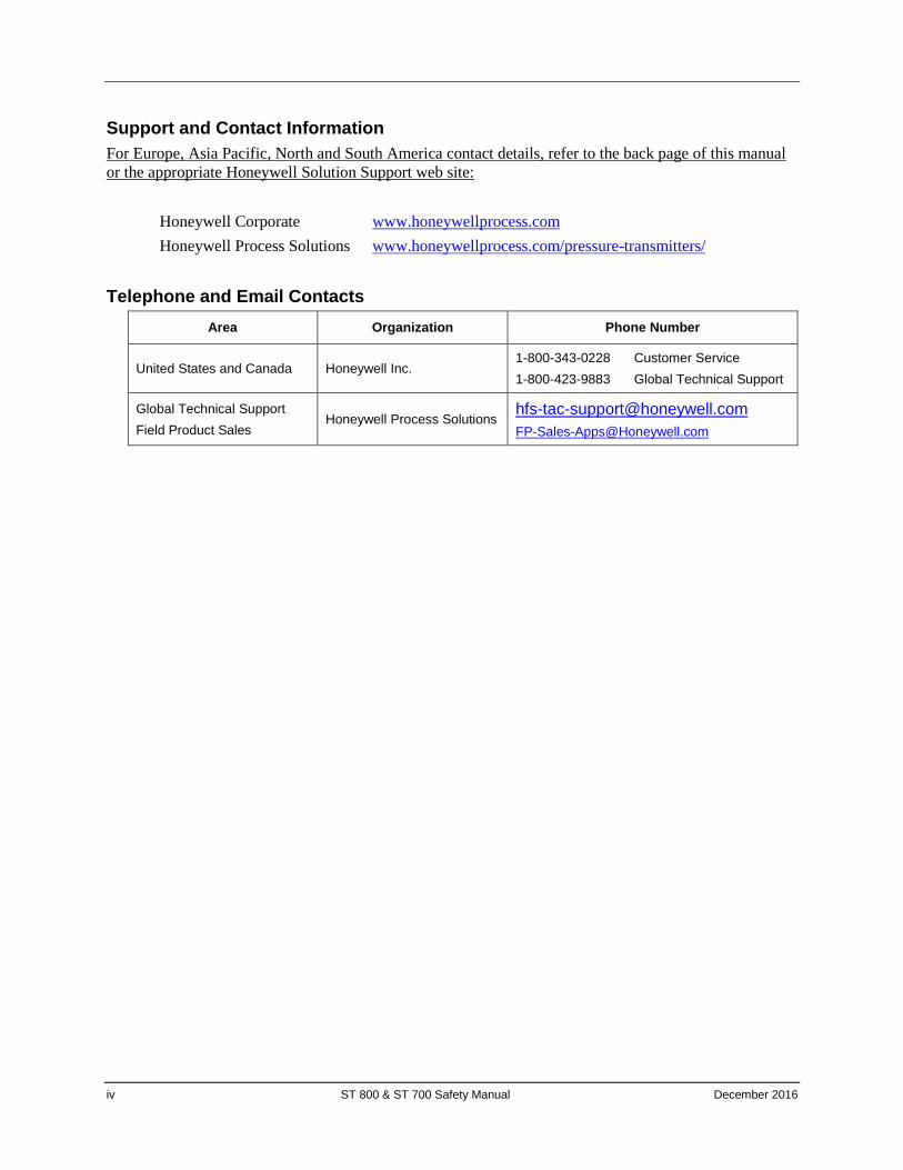
Support and Contact Information
For Europe, Asia Pacific, North and South America contact details, refer to the back page of this manual
or the appropriate Honeywell Solution Support web site:
Honeywell Corporate www.honeywellprocess.com
Honeywell Process Solutions www.honeywellprocess.com/pressure-transmitters/
Telephone and Email Contacts
Area Organization Phone Number
United States and Canada Honeywell Inc. 1-800-343-0228 Customer Service
1-800-423-9883 Global Technical Support
Global Technical Support
Field Product Sales Honeywell Process Solutions
December 2016 ST 800 & ST 700 Safety Manual v
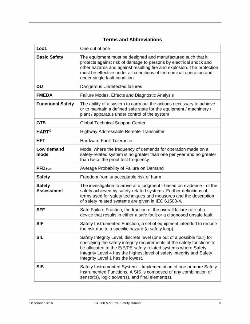
Terms and Abbreviations
1oo1 One out of one
Basic Safety The equipment must be designed and manufactured such that it protects against risk of damage to persons by electrical shock and other hazards and against resulting fire and explosion. The protection must be effective under all conditions of the nominal operation and under single fault condition
DU Dangerous Undetected failures
FMEDA Failure Modes, Effects and Diagnostic Analysis
Functional Safety The ability of a system to carry out the actions necessary to achieve or to maintain a defined safe state for the equipment / machinery / plant / apparatus under control of the system
GTS Global Technical Support Center
HART® Highway Addressable Remote Transmitter
HFT Hardware Fault Tolerance
Low demand mode
Mode, where the frequency of demands for operation made on a safety-related system is no greater than one per year and no greater than twice the proof test frequency.
PFDAVG Average Probability of Failure on Demand
Safety Freedom from unacceptable risk of harm
Safety Assessment
The investigation to arrive at a judgment - based on evidence - of the safety achieved by safety-related systems. Further definitions of terms used for safety techniques and measures and the description of safety related systems are given in IEC 61508-4.
SFF Safe Failure Fraction, the fraction of the overall failure rate of a device that results in either a safe fault or a diagnosed unsafe fault.
SIF Safety Instrumented Function, a set of equipment intended to reduce the risk due to a specific hazard (a safety loop).
SIL Safety Integrity Level, discrete level (one out of a possible four) for specifying the safety integrity requirements of the safety functions to be allocated to the E/E/PE safety-related systems where Safety Integrity Level 4 has the highest level of safety integrity and Safety Integrity Level 1 has the lowest.
SIS Safety Instrumented System – Implementation of one or more Safety Instrumented Functions. A SIS is composed of any combination of sensor(s), logic solver(s), and final element(s).
vi ST 800 & ST 700 Safety Manual December 2016
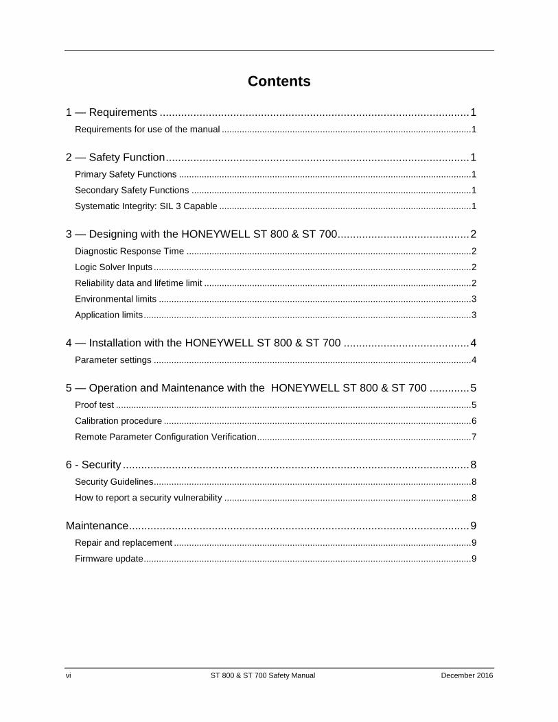
Contents
1 — Requirements ..................................................................................................... 1
Requirements for use of the manual ................................................................................................... 1
2 — Safety Function ................................................................................................... 1
Primary Safety Functions .................................................................................................................... 1
Secondary Safety Functions ............................................................................................................... 1
Systematic Integrity: SIL 3 Capable .................................................................................................... 1
3 — Designing with the HONEYWELL ST 800 & ST 700 ........................................... 2
Diagnostic Response Time ................................................................................................................. 2
Logic Solver Inputs .............................................................................................................................. 2
Reliability data and lifetime limit .......................................................................................................... 2
Environmental limits ............................................................................................................................ 3
Application limits .................................................................................................................................. 3
4 — Installation with the HONEYWELL ST 800 & ST 700 ......................................... 4
Parameter settings .............................................................................................................................. 4
5 — Operation and Maintenance with the HONEYWELL ST 800 & ST 700 ............. 5
Proof test ............................................................................................................................................. 5
Calibration procedure .......................................................................................................................... 6
Remote Parameter Configuration Verification ..................................................................................... 7
6 - Security ................................................................................................................. 8
Security Guidelines .............................................................................................................................. 8
How to report a security vulnerability .................................................................................................. 8
Maintenance ............................................................................................................... 9
Repair and replacement ...................................................................................................................... 9
Firmware update .................................................................................................................................. 9
December 2016 ST 800 & ST 700 Safety Manual 1
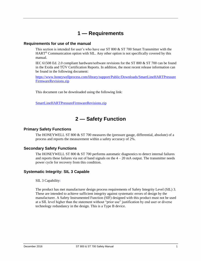
1 — Requirements
Requirements for use of the manual
This section is intended for user’s who have our ST 800 & ST 700 Smart Transmitter with the
HART® Communication option with SIL. Any other option is not specifically covered by this
manual.
IEC 61508 Ed. 2.0 compliant hardware/software revisions for the ST 800 & ST 700 can be found
in the Exida and TÜV Certification Reports. In addition, the most recent release information can
be found in the following document:
https://www.honeywellprocess.com/library/support/Public/Downloads/SmartLineHARTPressure
FirmwareRevisions.zip
This document can be downloaded using the following link:
SmartLineHARTPressureFirmwareRevisions.zip
2 — Safety Function
Primary Safety Functions
The HONEYWELL ST 800 & ST 700 measures the (pressure gauge, differential, absolute) of a
process and reports the measurement within a safety accuracy of 2%.
Secondary Safety Functions
The HONEYWELL ST 800 & ST 700 performs automatic diagnostics to detect internal failures
and reports these failures via out of band signals on the 4 – 20 mA output. The transmitter needs
power cycle for recovery from this condition.
Systematic Integrity: SIL 3 Capable
SIL 3 Capability:
The product has met manufacturer design process requirements of Safety Integrity Level (SIL) 3.
These are intended to achieve sufficient integrity against systematic errors of design by the
manufacturer. A Safety Instrumented Function (SIF) designed with this product must not be used
at a SIL level higher than the statement without “prior use” justification by end user or diverse
technology redundancy in the design. This is a Type B device.
2 ST 800 & ST 700 Safety Manual December 2016
3 — Designing with the HONEYWELL ST 800 & ST 700
Diagnostic Response Time
The HONEYWELL ST 800 & ST 700 will report an internal failure within 14 minutes of fault
occurrence (worst case).
The transmitter will be put to burnout current if
1. PV is not updated in 5 seconds
2. Current is not as expected in 40 seconds
3. Electronics fault is found in 14 minutes
The transmitter needs power cycle for recovery from this condition.
Logic Solver Inputs
The logic solver must be configured so that the engineering range in the transmitter matches the
expected range of the logic solver.
To take advantage of the internal diagnostics in the ST 800 & ST 700, the logic solver must be
configured to annunciate an out of band current reading (greater than 20.8 mA. or less than 3.8
mA.) in standard configuration or (greater than 20.5 mA. or less than 3.8 mA.) with Namur
configuration as a diagnostic fault. The logic solver configuration must consider the slew time of
the current signal and ensure that filtering is used to prevent a false diagnostic failure
annunciation.
Reliability data and lifetime limit
A detailed Failure Mode, Effects, and Diagnostics Analysis (FMEDA) report is available from
HONEYWELL. This report details all failure rates and failure modes, common cause factors for
applications with redundant devices and the expected lifetime of the HONEYWELL ST 800 &
ST 700.
The HONEYWELL ST 800 & ST 700 is intended for low demand mode applications up to SIL 2
for use in a simplex (1oo1) configuration, depending on the PFDAVG calculation of the entire
Safety Instrumented Function. ST 800 & ST 700 is classified as type B device according to
IEC61508, having a hardware fault tolerance of 0.
The development process of the HONEYWELL ST 800 & ST 700 is certified up to SIL3,
allowing redundant use of the transmitter up to this Safety Integrity Level, depending the PFDAVG
calculation of the entire Safety Instrumented Function.
When using the HONEYWELL ST 800 & ST 700 in a redundant configuration, a common cause
factor should be included in reliability calculations. For reliability calculation details, useful
lifetime and SFF, see the FMEDA report.
The reliability data listed the FMEDA report is only valid for the useful life time of the
HONEYWELL ST 800 & ST 700. The failure rates of the HONEYWELL ST 800 & ST 700 may
increase sometime after this period. Reliability calculations based on the data listed in the
FMEDA report for mission times beyond the lifetime may yield results that are too optimistic, i.e.
the calculated Safety Integrity Level will not be achieved.
December 2016 ST 800 & ST 700 Safety Manual 3
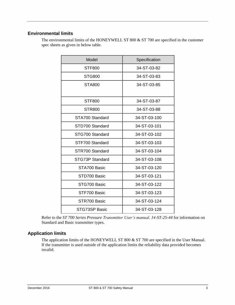
Environmental limits
The environmental limits of the HONEYWELL ST 800 & ST 700 are specified in the customer
spec sheets as given in below table.
Model Specification
STF800 34-ST-03-82
STG800 34-ST-03-83
STA800 34-ST-03-85
STF800 34-ST-03-87
STR800 34-ST-03-88
STA700 Standard 34-ST-03-100
STD700 Standard 34-ST-03-101
STG700 Standard 34-ST-03-102
STF700 Standard 34-ST-03-103
STR700 Standard 34-ST-03-104
STG73P Standard 34-ST-03-108
STA700 Basic 34-ST-03-120
STD700 Basic 34-ST-03-121
STG700 Basic 34-ST-03-122
STF700 Basic 34-ST-03-123
STR700 Basic 34-ST-03-124
STG73SP Basic 34-ST-03-128
Refer to the ST 700 Series Pressure Transmitter User’s manual, 34-ST-25-44 for information on
Standard and Basic transmitter types.
Application limits
The application limits of the HONEYWELL ST 800 & ST 700 are specified in the User Manual.
If the transmitter is used outside of the application limits the reliability data provided becomes
invalid.
4 ST 800 & ST 700 Safety Manual December 2016
4 — Installation with the HONEYWELL ST 800 & ST 700
The person with knowledge of safety operations will be required to do the installation and
operation. No special installation is required in addition to the standard installation practices
outlined in the ST 800 & ST 700 Smart Transmitter User Manual. However please note that when
the device is in safety operation the optional write protect must be set in hardware and software
both so that the device is write protected and HART® devices must be disconnected. This can be
done using the write protect jumper. See ST 800 & ST 700 Smart Transmitter User Manual for
details concerning the write protect jumper.
The software write protect is also available in the device with a password to disable the software
write protect. The default password is “0000”. It can be enabled / disabled through HART host.
IEC 61508 Ed. 2.0 compliant hardware/software revisions for the ST 800 & ST 700 can be found
in the Exida and TÜV Certification Reports. In addition, the most recent release information can
be found in the following document:
https://www.honeywellprocess.com/library/support/Public/Downloads/SmartLineHARTPressureFirmwareRevisions.zip
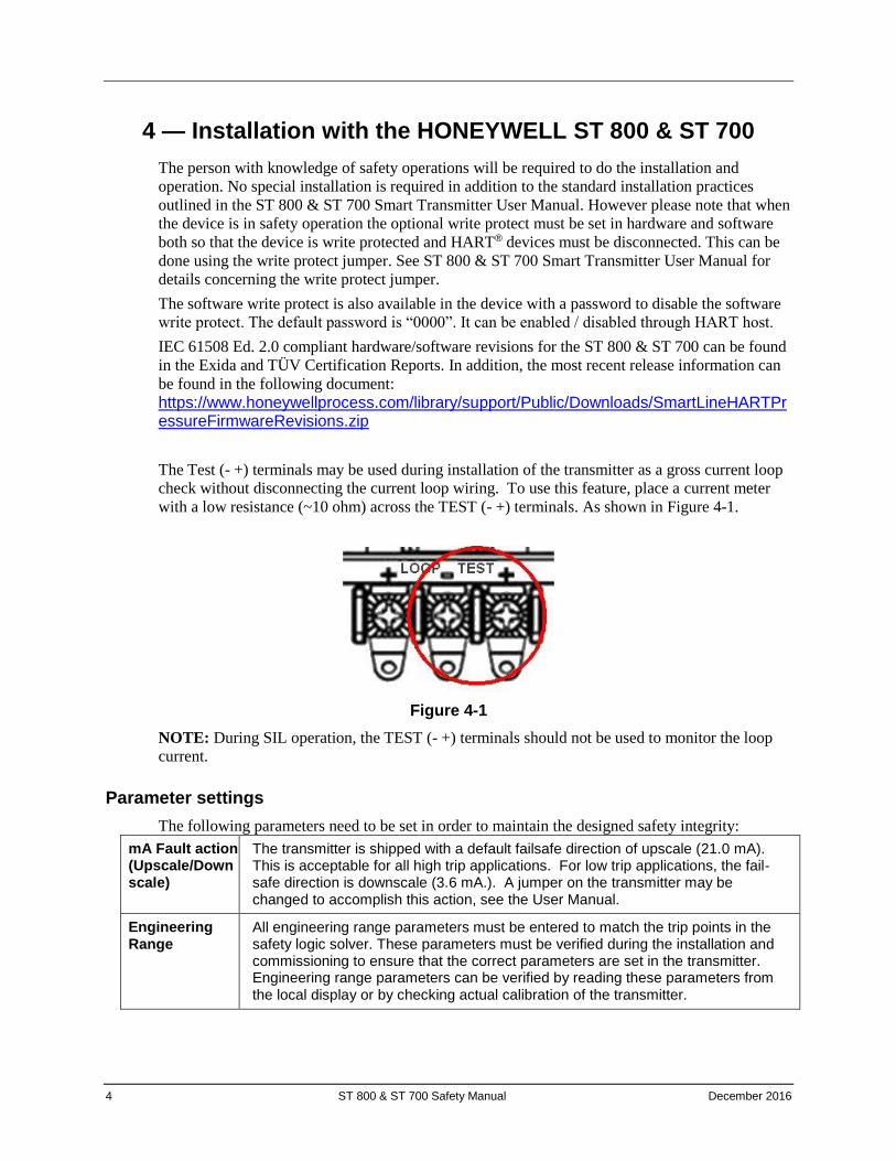
The Test (- +) terminals may be used during installation of the transmitter as a gross current loop
check without disconnecting the current loop wiring. To use this feature, place a current meter
with a low resistance (~10 ohm) across the TEST (- +) terminals. As shown in Figure 4-1.
Figure 4-1
NOTE: During SIL operation, the TEST (- +) terminals should not be used to monitor the loop
current.
Parameter settings
The following parameters need to be set in order to maintain the designed safety integrity:
mA Fault action (Upscale/Downscale)
The transmitter is shipped with a default failsafe direction of upscale (21.0 mA). This is acceptable for all high trip applications. For low trip applications, the fail-safe direction is downscale (3.6 mA.). A jumper on the transmitter may be changed to accomplish this action, see the User Manual.
Engineering Range
All engineering range parameters must be entered to match the trip points in the safety logic solver. These parameters must be verified during the installation and commissioning to ensure that the correct parameters are set in the transmitter. Engineering range parameters can be verified by reading these parameters from the local display or by checking actual calibration of the transmitter.
December 2016 ST 800 & ST 700 Safety Manual 5
5 — Operation and Maintenance with the HONEYWELL ST 800 & ST 700
Proof test
The objective of proof testing is to detect failures within the HONEYWELL ST 800 & ST 700
that are not detected by the automatic diagnostics of the transmitter. Of main concern are
undetected failures that prevent the safety instrumented function from performing its intended
function.
The frequency of proof testing, or the proof test interval, is to be determined in reliability
calculations for the safety instrumented functions for which the HONEYWELL ST 800 & ST 700
is applied. The Exida exSILentia® tool is recommended for these calculations. The proof tests
must be performed more frequently than, or as frequently as specified in the calculation in order
to maintain the required safety integrity of the safety instrumented function.
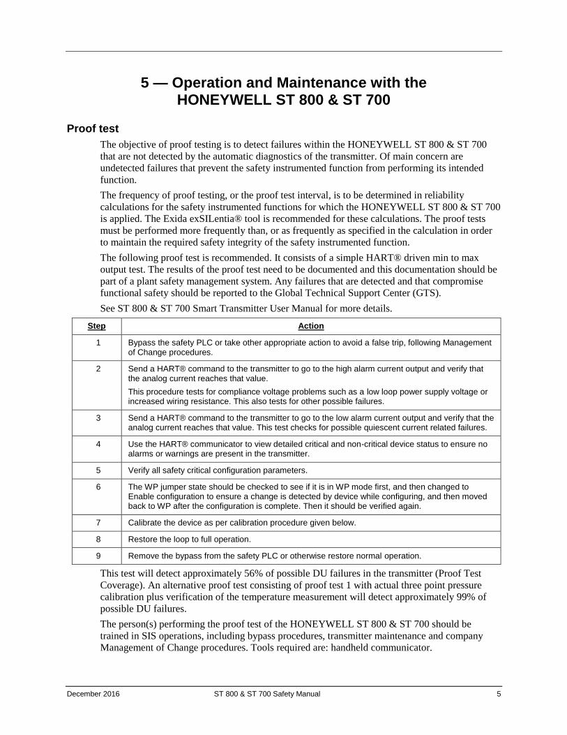
The following proof test is recommended. It consists of a simple HART® driven min to max
output test. The results of the proof test need to be documented and this documentation should be
part of a plant safety management system. Any failures that are detected and that compromise
functional safety should be reported to the Global Technical Support Center (GTS).
See ST 800 & ST 700 Smart Transmitter User Manual for more details.
Step Action
1 Bypass the safety PLC or take other appropriate action to avoid a false trip, following Management of Change procedures.
2 Send a HART® command to the transmitter to go to the high alarm current output and verify that the analog current reaches that value.
This procedure tests for compliance voltage problems such as a low loop power supply voltage or increased wiring resistance. This also tests for other possible failures.
3 Send a HART® command to the transmitter to go to the low alarm current output and verify that the analog current reaches that value. This test checks for possible quiescent current related failures.
4 Use the HART® communicator to view detailed critical and non-critical device status to ensure no alarms or warnings are present in the transmitter.
5 Verify all safety critical configuration parameters.
6 The WP jumper state should be checked to see if it is in WP mode first, and then changed to Enable configuration to ensure a change is detected by device while configuring, and then moved back to WP after the configuration is complete. Then it should be verified again.
7 Calibrate the device as per calibration procedure given below.
8 Restore the loop to full operation.
9 Remove the bypass from the safety PLC or otherwise restore normal operation.
This test will detect approximately 56% of possible DU failures in the transmitter (Proof Test
Coverage). An alternative proof test consisting of proof test 1 with actual three point pressure
calibration plus verification of the temperature measurement will detect approximately 99% of
possible DU failures.
The person(s) performing the proof test of the HONEYWELL ST 800 & ST 700 should be
trained in SIS operations, including bypass procedures, transmitter maintenance and company
Management of Change procedures. Tools required are: handheld communicator.
6 ST 800 & ST 700 Safety Manual December 2016
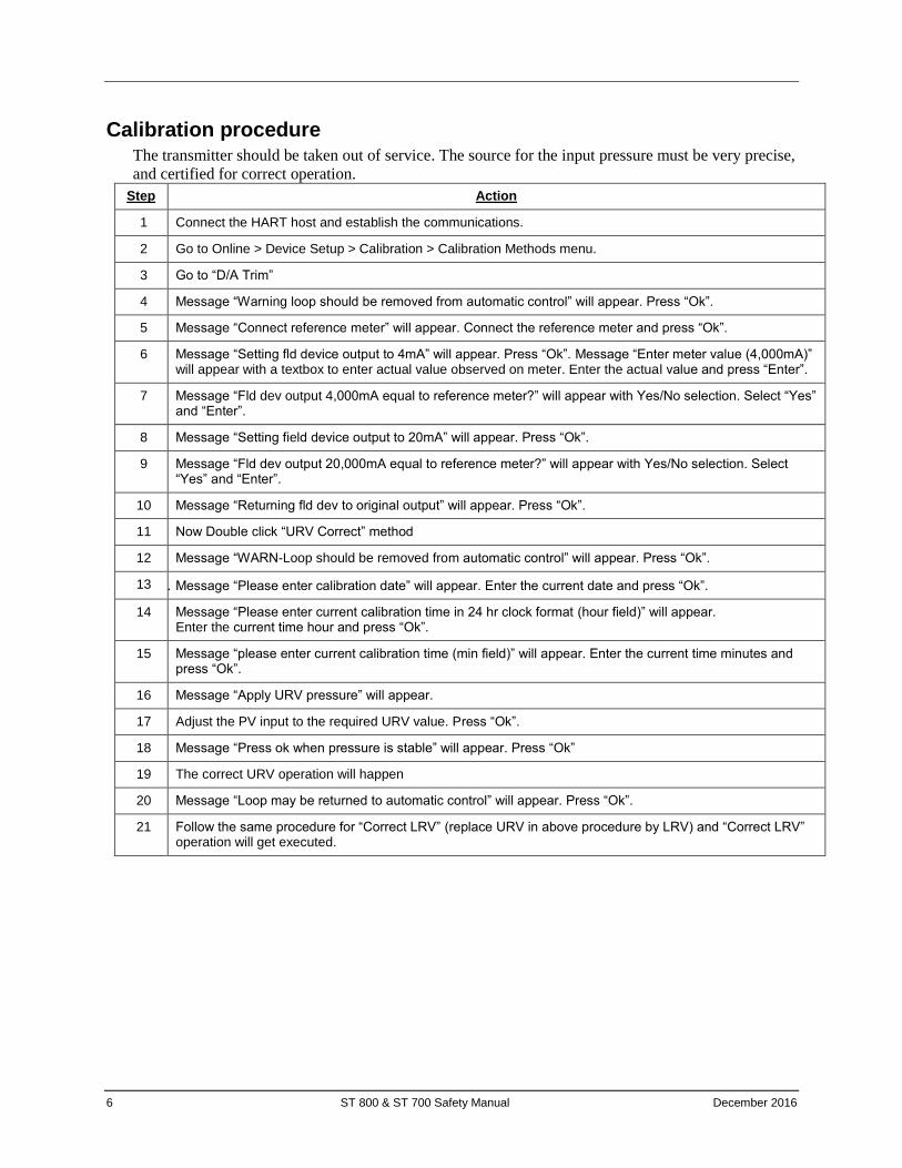
Calibration procedure The transmitter should be taken out of service. The source for the input pressure must be very precise,
and certified for correct operation.
Step Action
1 Connect the HART host and establish the communications.
2 Go to Online > Device Setup > Calibration > Calibration Methods menu.
3 Go to “D/A Trim”
4 Message “Warning loop should be removed from automatic control” will appear. Press “Ok”.
5 Message “Connect reference meter” will appear. Connect the reference meter and press “Ok”.
6 Message “Setting fld device output to 4mA” will appear. Press “Ok”. Message “Enter meter value (4,000mA)” will appear with a textbox to enter actual value observed on meter. Enter the actual value and press “Enter”.
7 Message “Fld dev output 4,000mA equal to reference meter?” will appear with Yes/No selection. Select “Yes” and “Enter”.
8 Message “Setting field device output to 20mA” will appear. Press “Ok”.
9 Message “Fld dev output 20,000mA equal to reference meter?” will appear with Yes/No selection. Select “Yes” and “Enter”.
10 Message “Returning fld dev to original output” will appear. Press “Ok”.
11 Now Double click “URV Correct” method
12 Message “WARN-Loop should be removed from automatic control” will appear. Press “Ok”.
13 1. Message “Please enter calibration date” will appear. Enter the current date and press “Ok”.
14 Message “Please enter current calibration time in 24 hr clock format (hour field)” will appear. Enter the current time hour and press “Ok”.
15 Message “please enter current calibration time (min field)” will appear. Enter the current time minutes and press “Ok”.
16 Message “Apply URV pressure” will appear.
17 Adjust the PV input to the required URV value. Press “Ok”.
18 Message “Press ok when pressure is stable” will appear. Press “Ok”
19 The correct URV operation will happen
20 Message “Loop may be returned to automatic control” will appear. Press “Ok”.
21 Follow the same procedure for “Correct LRV” (replace URV in above procedure by LRV) and “Correct LRV” operation will get executed.
December 2016 ST 800 & ST 700 Safety Manual 7
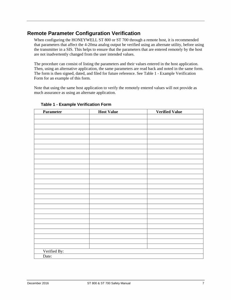
Remote Parameter Configuration Verification When configuring the HONEYWELL ST 800 or ST 700 through a remote host, it is recommended
that parameters that affect the 4-20ma analog output be verified using an alternate utility, before using
the transmitter in a SIS. This helps to ensure that the parameters that are entered remotely by the host
are not inadvertently changed from the user intended values.
The procedure can consist of listing the parameters and their values entered in the host application.
Then, using an alternative application, the same parameters are read back and noted in the same form.
The form is then signed, dated, and filed for future reference. See Table 1 - Example Verification
Form for an example of this form.
Note that using the same host application to verify the remotely entered values will not provide as
much assurance as using an alternate application.
Table 1 - Example Verification Form
Parameter Host Value Verified Value
Verified By:
Date:
8 ST 800 & ST 700 Safety Manual December 2016
6 - Security
Security Guidelines
1. Ensure the device has Hardware/ Software write protect on enabled the device to prevent
any unauthorized configuration changes.
2. Physical access to device: A malicious operation on the transmitters will result in system
shutdown, starting the system expectedly or impact process control. For maximum security,
the transmitter device must be protected against unauthorized physical access.
3. Be aware of any unauthorized access of a secondary master alarm present in Distributed
Control System (DCS). If this is because of a secondary handheld device being connected
then this can be ignored.
4. Enable the Tamper alarm and monitor the Tamper Counter value for unintended changes.
How to report a security vulnerability
For the purpose of submission, a security vulnerability is defined as a software defect or
weakness that can be exploited to reduce the operational or security capabilities of the software or
device.
Honeywell investigates all reports of security vulnerabilities affecting Honeywell products and
services.
To report potential security vulnerability against any Honeywell product, please follow the
instructions at:
https://honeywell.com/pages/vulnerabilityreporting.aspx
Submit the requested information to Honeywell using one of the following methods:
• Send an email to [email protected].
or
• Contact your local Honeywell Process Solutions Customer Contact Centre (CCC) or Honeywell
Technical Assistance Centre (TAC) listed in the “Support and Contact information” section of
this document.
December 2016 ST 800 & ST 700 Safety Manual 9
Maintenance
Repair and replacement
Any failures that are detected and that compromise functional safety should be reported to the
Global Technical Support Center (GTS).
When replacing the HONEYWELL ST 800 & ST 700 the procedures in the installation manual
should be followed.
Firmware update
The user will not be required to perform any firmware updates. If the user has selected the
firmware upgrade option, it can be done by Honeywell service representative.
For more information
To learn more about SmartLine Transmitters, visit www.honeywellprocess.com
Or contact your Honeywell Account Manager
Process Solutions
Honeywell
1250 W Sam Houston Pkwy S Houston, TX 77042
Honeywell Control Systems Ltd Honeywell House, Skimped Hill Lane Bracknell, England, RG12 1EB
34-ST-25-37 Rev.6 December 2016
2016 Honeywell International Inc.
Shanghai City Centre, 100 Jungi Road Shanghai, China 20061 www.honeywellprocess.com
Sales and Service
For application assistance, current specifications, pricing, or name of the nearest Authorized Distributor, contact one of the offices below.
ASIA PACIFIC Honeywell Process Solutions,
(TAC) [email protected]
Australia Honeywell Limited Phone: +(61) 7-3846 1255 FAX: +(61) 7-3840 6481 Toll Free 1300-36-39-36 Toll Free Fax: 1300-36-04-70 China – PRC - Shanghai Honeywell China Inc. Phone: (86-21) 5257-4568 Fax: (86-21) 6237-2826
Singapore Honeywell Pte Ltd. Phone: +(65) 6580 3278 Fax: +(65) 6445-3033 South Korea Honeywell Korea Co Ltd Phone: +(822) 799 6114 Fax: +(822) 792 9015
EMEA Honeywell Process Solutions,
Phone: + 80012026455 or +44 (0)1344 656000
Email: (Sales)
or
(TAC)
AMERICA’S Honeywell Process Solutions,
Phone: (TAC) 1-800-423-9883 or 215/641-3610
(Sales) 1-800-343-0228
Email: (Sales)
or
(TAC)