Embed Size (px)
Citation preview
International Journal of Scientific and Research Publications, Volume 4, Issue 5, May 2014 1 ISSN 2250-3153
www.ijsrp.org
Stability Analysis of AC Transmission Line Using FACTS *Chonika, *Manoj,
**Mr. Kumar Dhiraj
*P.G. Student, Conrol & Instrumentation, BRCM College of Engineering & Technology, India
**Assistant professor EEE Department BRCM College of Engineering & Technology, India
Abstract- Due to the rapid technological progress, the
consumption of electric energy increases continuously. But the
transmission systems are not extended to the same extent because
building of new lines is difficult for environmental as well as
political reasons. Hence, the systems are driven closer to their
limits resulting in congestions and critical situations endangering
the system security. Power Flow Control devices such as Flexible
AC Transmission Systems (FACTS) provide the opportunity to
influence power flows and voltages and therefore to enhance
system security, e.g. by resolving congestions and improving the
voltage profile. Several kinds of FACTS controllers have been
commissioned in various parts of the world. This paper presents
various types of FACTS devices such as: load tap changers,
phase-angle regulators, static VAR compensators, thyristor-
controlled series compensators, interphase power controllers,
static compensators, and unified power flow controllers. There
classification based on steady sate and transient state stability
and Power electronic and control technology have been studied.
I. INTRODUCTION
owadays changing electric power systems generate a
growing need for reliability, flexibility, fast response and
accuracy in the fields of electric power generation, transmission,
distribution and consumption. An efficient, reliable transmission
system will persist to have a vital role in satisfying the nation’s
growing thirst for electricity. The transmission system of the
future (Smart Transmission) is the logical extension of today’s
electric grid. Transmission has a long history of installing new
technologies that always improve performance in reply to the
varying needs of society. This approach of innovation is required
today, more than ever before. A transmission system that is both
bigger and smarter than today’s system is wanted to meet the
nation’s goal of a sustainable future for electric energy. The
transmission system is the high-voltage part of the electric power
infrastructure responsible for the bulk transfer of electricity from
power plants to substations located near population centres.
Transmission and Distribution (T&D) losses between 6% and 8%
are considered normal [1].
As utilities shift forward with smart grid uses, there has never
been a better time to think about the use of advanced power
electronics as a workable transmission planning choice. With the
use of FACTS Devices known as flexible AC transmission
systems, the future of electric transmission systems can be smart.
FACTS can raise transmission to a new level of performance and
can provide a variety of benefits for increasing transmission
efficiency [2]. There are two generations for realization of
power electronics-based FACTS controllers: the first generation
employs conventional thyristor-switched capacitors and reactors,
quadrature tap-changing transformers, that second generation
employs gate turn-off (GTO) thyristor-switched converters as
voltage source converters (VSCs). The first generation has
resulted in the Static Var Compensator (SVC), the Thyristor-
Controlled Series Capacitor (TCSC), and the Thyristor-
Controlled Phase Shifter (TCPS). The second generation has
produced the Static Synchronous Compensator (STATCOM), the
Static Synchronous Series Compensator (SSSC), the Unified
Power Flow Controller (UPFC) [1], [3] and the Interline Power
Flow Controller (IPFC).the system, large dynamic swings
between different parts of the system and bottlenecks [4]. In this
paper classification of Facts devices based on stability will be
discussed.
II. INHERENT LIMITATIONS OF TRANSMISSION
SYSTEMS
The characteristics of a given power system evolve with time,
as load grows and generation is added. If the transmission
facilities are not upgraded sufficiently the power system becomes
vulnerable to steady state and transient stability problems, as
stability margins become narrower [5].
The ability of the transmission system to transmit power
becomes impaired by one or more of the following steady-state
and dynamic limitations [6]:
_ angular stability;
_ voltage magnitude;
_ thermal limits;
_ transient stability;
_ dynamic stability.
These limits define the maximum electrical power to be
transmitted without causing damage to transmission lines and
electric equipment. In principle, limitations on power transfer can
always be relieved by the addition of new transmission and
generation facilities. Alternatively, FACTS controllers can
enable the same objectives to be met with no major alterations to
system layout. The potential benefits brought about by FACTS
controllers include reduction of operation and transmission
investment cost, increased system security and reliability,
increased power transfer capabilities, and an overall
enhancement of the quality of the electric energy delivered to
customers [7].
III. STABILITY
The stability of a system refers to the ability of a system to
return to its steady state when subjected to a disturbance. As
mentioned before, power is generated by synchronous generators
that operate in synchronism with the rest of the system. A
N
International Journal of Scientific and Research Publications, Volume 4, Issue 5, May 2014 2
ISSN 2250-3153
www.ijsrp.org
generator is synchronized with a bus when both of them have
same frequency, voltage and phase sequence. We can thus define
the power system stability as the ability of the power system to
return to steady state without losing synchronism. Usually power
system stability is categorized into Steady State, Transient and
Dynamic Stability
a) Steady State Stability studies are restricted to small and
gradual changes in the system operating conditions. In
this we basically concentrate on restricting the bus
voltages close to their nominal values. We also ensure
that phase angles between two buses are not too large
and check for the overloading of the power equipment
and transmission lines. These checks are usually done
using power flow studies.
b) Transient Stability involves the study of the power
system following a major disturbance. Following a large
disturbance the synchronous alternator the machine
power (load) angle changes due to sudden acceleration
of the rotor shaft. The objective of the transient stability
study is to ascertain whether the load angle returns to a
steady value following the clearance of the disturbance
c) The ability of a power system to maintain stability
under continuous small disturbances is investigated
under the name of Dynamic Stability (also known as
small-signal stability). These small disturbances occur
due random fluctuations in loads and generation levels.
In an interconnected power system, these random
variations can lead catastrophic failure as this may force
the rotor angle to increase steadily.
IV. FACTS CONTROLLERS
Power flow control has traditionally relied on generator
control, voltage regulation by means of tap-changing and phase-
shifting transformers, and reactive power plant compensation
switching. Phase-shifting transformers have been used for the
purpose of regulating active power in alternating current (AC)
transmission networks. A number of FACTS controllers have
been commissioned. Most of them perform a useful role during
both steady-state and transient operation, but some are
specifically designed to operate only under transient conditions.
FACTS controllers intended for steady-state operation are as
follows:
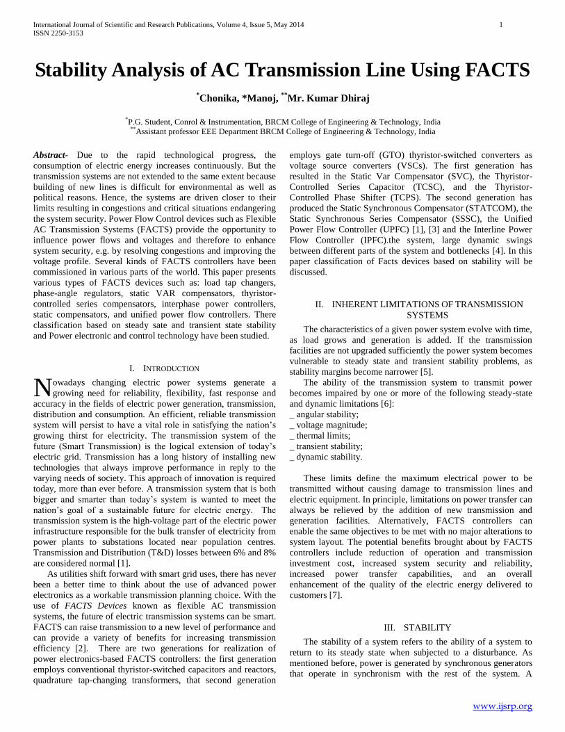
Thyristor-controlled phase shifter (PS):
This controller is an electronic phase-shifting transformer
adjusted by thyristor switches to provide a rapidly varying phase
angle. Figure 1 shows the schematic diagram of the Thyristor
Controlled Phase Shifter (TCPS). The series transformer injects
the voltage in series in the system. The active and reactive power
injected by the series transformer is taken from the shunt
transformer. For sake simplicity of analysis, the insignificant
losses from transformer and converter is neglected. Thus the net
complex power (real and reactive power) exchange between the
TCPS and the system is zero. The injection of this complex
power depends on the injection of a series voltage controlled by a
converter.
Fig. 1 Schematic Diagram Of The Thyristor Controlled
Phase Shifter
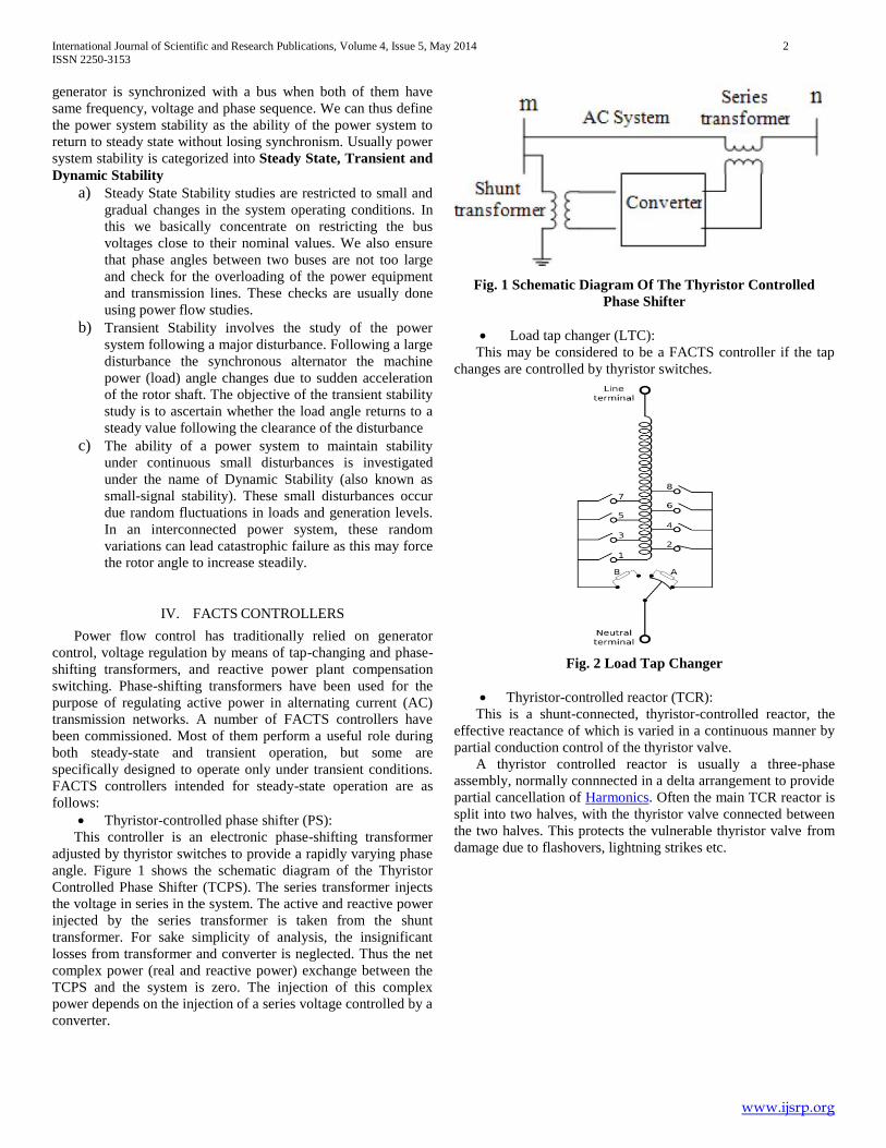
Load tap changer (LTC):
This may be considered to be a FACTS controller if the tap
changes are controlled by thyristor switches.
Fig. 2 Load Tap Changer
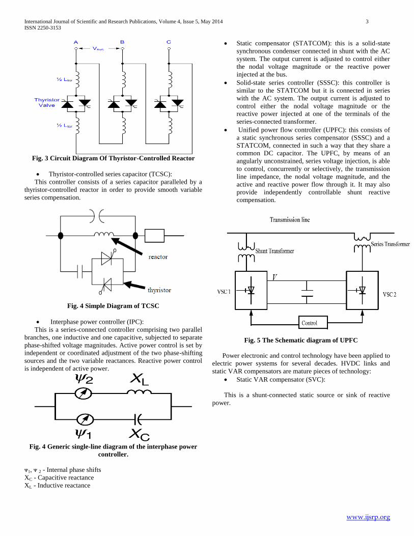
Thyristor-controlled reactor (TCR):
This is a shunt-connected, thyristor-controlled reactor, the
effective reactance of which is varied in a continuous manner by
partial conduction control of the thyristor valve.
A thyristor controlled reactor is usually a three-phase
assembly, normally connnected in a delta arrangement to provide
partial cancellation of Harmonics. Often the main TCR reactor is
split into two halves, with the thyristor valve connected between
the two halves. This protects the vulnerable thyristor valve from
damage due to flashovers, lightning strikes etc.
International Journal of Scientific and Research Publications, Volume 4, Issue 5, May 2014 3
ISSN 2250-3153
www.ijsrp.org
Fig. 3 Circuit Diagram Of Thyristor-Controlled Reactor
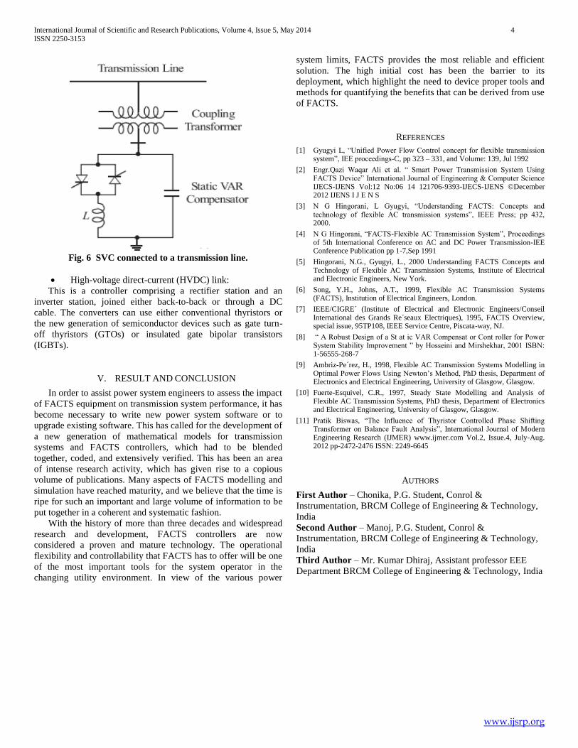
Thyristor-controlled series capacitor (TCSC):
This controller consists of a series capacitor paralleled by a
thyristor-controlled reactor in order to provide smooth variable
series compensation.
Fig. 4 Simple Diagram of TCSC
Interphase power controller (IPC):
This is a series-connected controller comprising two parallel
branches, one inductive and one capacitive, subjected to separate
phase-shifted voltage magnitudes. Active power control is set by
independent or coordinated adjustment of the two phase-shifting
sources and the two variable reactances. Reactive power control
is independent of active power.
Fig. 4 Generic single-line diagram of the interphase power
controller.
ᴪ1, ᴪ 2 - Internal phase shifts
XC - Capacitive reactance
XL - Inductive reactance
Static compensator (STATCOM): this is a solid-state
synchronous condenser connected in shunt with the AC
system. The output current is adjusted to control either
the nodal voltage magnitude or the reactive power
injected at the bus.
Solid-state series controller (SSSC): this controller is
similar to the STATCOM but it is connected in series
with the AC system. The output current is adjusted to
control either the nodal voltage magnitude or the
reactive power injected at one of the terminals of the
series-connected transformer.
Unified power flow controller (UPFC): this consists of
a static synchronous series compensator (SSSC) and a
STATCOM, connected in such a way that they share a
common DC capacitor. The UPFC, by means of an
angularly unconstrained, series voltage injection, is able
to control, concurrently or selectively, the transmission
line impedance, the nodal voltage magnitude, and the
active and reactive power flow through it. It may also
provide independently controllable shunt reactive
compensation.
Fig. 5 The Schematic diagram of UPFC
Power electronic and control technology have been applied to
electric power systems for several decades. HVDC links and
static VAR compensators are mature pieces of technology:
Static VAR compensator (SVC):
This is a shunt-connected static source or sink of reactive
power.
International Journal of Scientific and Research Publications, Volume 4, Issue 5, May 2014 4
ISSN 2250-3153
www.ijsrp.org
Fig. 6 SVC connected to a transmission line.
High-voltage direct-current (HVDC) link:
This is a controller comprising a rectifier station and an
inverter station, joined either back-to-back or through a DC
cable. The converters can use either conventional thyristors or
the new generation of semiconductor devices such as gate turn-
off thyristors (GTOs) or insulated gate bipolar transistors
(IGBTs).
V. RESULT AND CONCLUSION
In order to assist power system engineers to assess the impact
of FACTS equipment on transmission system performance, it has
become necessary to write new power system software or to
upgrade existing software. This has called for the development of
a new generation of mathematical models for transmission
systems and FACTS controllers, which had to be blended
together, coded, and extensively verified. This has been an area
of intense research activity, which has given rise to a copious
volume of publications. Many aspects of FACTS modelling and
simulation have reached maturity, and we believe that the time is
ripe for such an important and large volume of information to be
put together in a coherent and systematic fashion.
With the history of more than three decades and widespread
research and development, FACTS controllers are now
considered a proven and mature technology. The operational
flexibility and controllability that FACTS has to offer will be one
of the most important tools for the system operator in the
changing utility environment. In view of the various power
system limits, FACTS provides the most reliable and efficient
solution. The high initial cost has been the barrier to its
deployment, which highlight the need to device proper tools and
methods for quantifying the benefits that can be derived from use
of FACTS.
REFERENCES
[1] Gyugyi L, “Unified Power Flow Control concept for flexible transmission system”, IEE proceedings-C, pp 323 – 331, and Volume: 139, Jul 1992
[2] Engr.Qazi Waqar Ali et al. “ Smart Power Transmission System Using FACTS Device” International Journal of Engineering & Computer Science IJECS-IJENS Vol:12 No:06 14 121706-9393-IJECS-IJENS ©December 2012 IJENS I J E N S
[3] N G Hingorani, L Gyugyi, “Understanding FACTS: Concepts and technology of flexible AC transmission systems”, IEEE Press; pp 432, 2000.
[4] N G Hingorani, “FACTS-Flexible AC Transmission System”, Proceedings of 5th International Conference on AC and DC Power Transmission-IEE Conference Publication pp 1-7,Sep 1991
[5] Hingorani, N.G., Gyugyi, L., 2000 Understanding FACTS Concepts and Technology of Flexible AC Transmission Systems, Institute of Electrical and Electronic Engineers, New York.
[6] Song, Y.H., Johns, A.T., 1999, Flexible AC Transmission Systems (FACTS), Institution of Electrical Engineers, London.
[7] IEEE/CIGRE´ (Institute of Electrical and Electronic Engineers/Conseil International des Grands Re´seaux Electriques), 1995, FACTS Overview, special issue, 95TP108, IEEE Service Centre, Piscata-way, NJ.
[8] “ A Robust Design of a St at ic VAR Compensat or Cont roller for Power System Stability Improvement ” by Hosseini and Mirshekhar, 2001 ISBN: 1-56555-268-7
[9] Ambriz-Pe´rez, H., 1998, Flexible AC Transmission Systems Modelling in Optimal Power Flows Using Newton’s Method, PhD thesis, Department of Electronics and Electrical Engineering, University of Glasgow, Glasgow.
[10] Fuerte-Esquivel, C.R., 1997, Steady State Modelling and Analysis of Flexible AC Transmission Systems, PhD thesis, Department of Electronics and Electrical Engineering, University of Glasgow, Glasgow.
[11] Pratik Biswas, “The Influence of Thyristor Controlled Phase Shifting Transformer on Balance Fault Analysis”, International Journal of Modern Engineering Research (IJMER) www.ijmer.com Vol.2, Issue.4, July-Aug. 2012 pp-2472-2476 ISSN: 2249-6645
AUTHORS
First Author – Chonika, P.G. Student, Conrol &
Instrumentation, BRCM College of Engineering & Technology,
India
Second Author – Manoj, P.G. Student, Conrol &
Instrumentation, BRCM College of Engineering & Technology,
India
Third Author – Mr. Kumar Dhiraj, Assistant professor EEE
Department BRCM College of Engineering & Technology, India


![2019. 01 FACTS(ENG).pdf · HVDC [High Voltage Direct Current Transmission System] FACTS [Flexible AC Transmission System] 4 . 5 47$ 4VCTUBUJPO ,PSFB 8PSME T MBSHFTU DBQBDJUZ JO B](https://img.pdfslide.net/doc/110x75/5eafd2f164b2502cb1357768/2019-01-factsengpdf-hvdc-high-voltage-direct-current-transmission-system.jpg)

![FACTS - LSISENG).pdf · 2019-07-02 · FACTS [Flexible AC Transmission System] 2 . 3 Electrical grid management The FACTS system can improve performance of transmission and disribution](https://img.pdfslide.net/doc/110x75/5eafd5b7cf13885b611c3931/facts-engpdf-2019-07-02-facts-flexible-ac-transmission-system-2-3-electrical.jpg)