Embed Size (px)
Citation preview
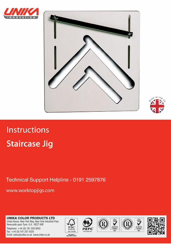
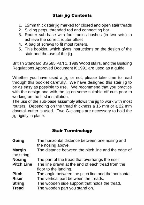
Stair jig Contents
1. 12mm thick stair jig marked for closed and open stair treads 2. Sliding pegs, threaded rod and connecting bar. 3. Router sub-base with four radius bushes (in two sets) to
achieve the correct router offset 4. A bag of screws to fit most routers. 5. This booklet, which gives instructions on the design of the
stair and the use of the jig. British Standard BS 585 Part 1, 1989 Wood stairs, and the Building Regulations Approved Document K 1991 are used as a guide. Whether you have used a jig or not, please take time to read through this booklet carefully. We have designed this stair jig to be as easy as possible to use. We recommend that you practice with the design and with the jig on some suitable off-cuts prior to working on the first installation. The use of the sub-base assembly allows the jig to work with most routers. Depending on the tread thickness a 16 mm or a 22 mm dovetail cutter is used. Two G-clamps are necessary to hold the jig rigidly in place.
Stair Terminology
Going The horizontal distance between one nosing and
the nosing above. Margin The distance between the pitch line and the edge of the string. Nosing The part of the tread that overhangs the riser Pitch Line The line drawn at the end of each tread from the
floor to the landing. Pitch The angle between the pitch line and the horizontal. Riser The vertical part between the treads. String The wooden side support that holds the tread. Tread The wooden part you stand on.
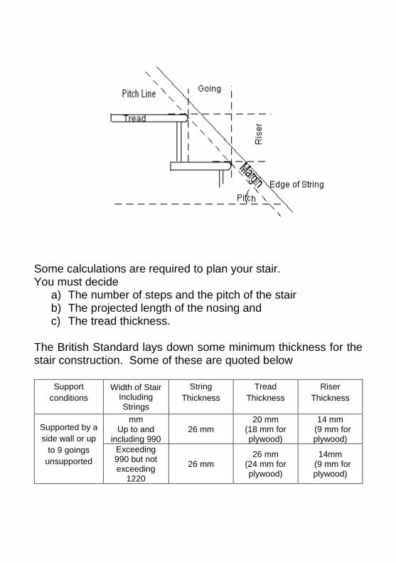
Some calculations are required to plan your stair. You must decide
a) The number of steps and the pitch of the stair b) The projected length of the nosing and c) The tread thickness.
The British Standard lays down some minimum thickness for the stair construction. Some of these are quoted below
Support
conditions
Width of Stair Including Strings
String
Thickness
Tread
Thickness
Riser
Thickness
Supported by a
side wall or up
to 9 goings
unsupported
mm Up to and
including 990 26 mm
20 mm (18 mm for plywood)
14 mm (9 mm for plywood)
Exceeding 990 but not exceeding
1220
26 mm 26 mm
(24 mm for plywood)
14mm (9 mm for plywood)
Planning the Stairs
The first thing to calculate is the Rise of the flight of stairs. The
normal Rise is between 170mm and 200mm. Calculate the total number of steps by selecting a Rise value between 170mm and 200mm, for example 185mm and divide the total rise of the flight of stairs by this value. For example, if the flight rise is 2.25 meters (2250mm) then the number of steps needed is 2250 divided by 185 or 12.16 steps. To overcome the 0.16 of a step, divide 2250 by 12 to calculate the true Rise of 187.5mm for this flight. The next thing calculated is the Going of the flight of stairs. This should be larger than 220mm for a private stairway or 250mm for a common stairway. If you decide on a Going, for example 240mm, then the flight will need 2880mm (240mm multiplied by 12 steps) of floor space to fit. If this is not the situation you must adjust the Rise and Going to fit the space available. Remember however, to meet the regulations BS 585, the value of twice the Rise value plus the Going value must lie between 550mm and 700mm.
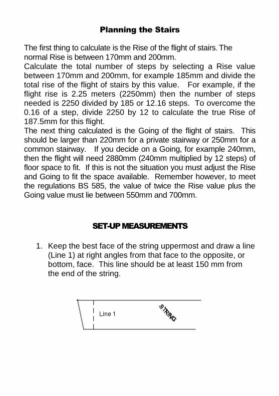
SET-UP MEASUREMENTS
1. Keep the best face of the string uppermost and draw a line (Line 1) at right angles from that face to the opposite, or bottom, face. This line should be at least 150 mm from the end of the string.
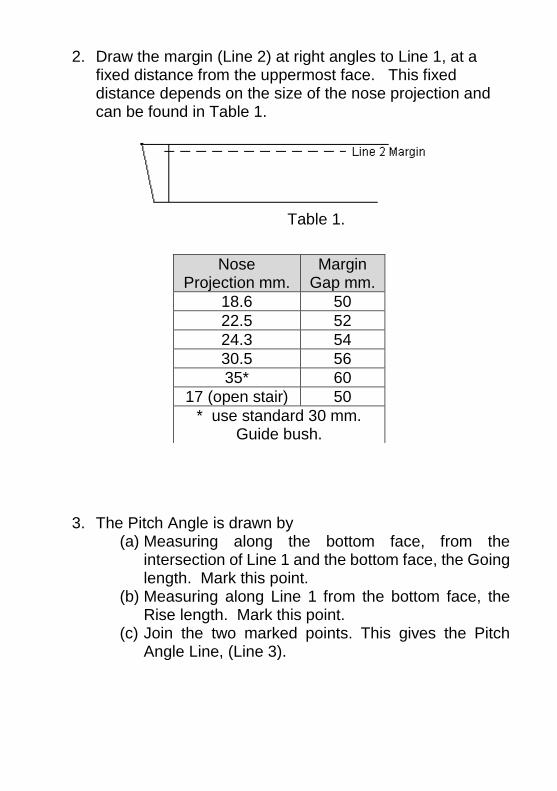
2. Draw the margin (Line 2) at right angles to Line 1, at a fixed distance from the uppermost face. This fixed distance depends on the size of the nose projection and can be found in Table 1.
Table 1.
3. The Pitch Angle is drawn by (a) Measuring along the bottom face, from the
intersection of Line 1 and the bottom face, the Going length. Mark this point.
(b) Measuring along Line 1 from the bottom face, the Rise length. Mark this point.
(c) Join the two marked points. This gives the Pitch Angle Line, (Line 3).
Nose Projection mm.
Margin Gap mm.
18.6 50
22.5 52
24.3 54
30.5 56
35* 60
17 (open stair) 50
* use standard 30 mm. Guide bush.
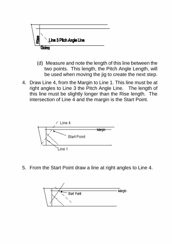
(d) Measure and note the length of this line between the two points. This length, the Pitch Angle Length, will be used when moving the jig to create the next step.
4. Draw Line 4, from the Margin to Line 1. This line must be at right angles to Line 3 the Pitch Angle Line. The length of this line must be slightly longer than the Rise length. The intersection of Line 4 and the margin is the Start Point.
5. From the Start Point draw a line at right angles to Line 4.
Fitting the Jig.
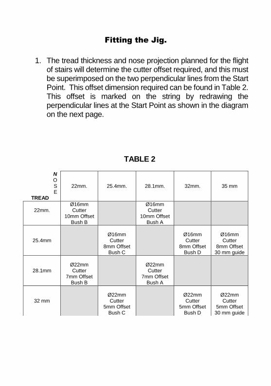
1. The tread thickness and nose projection planned for the flight of stairs will determine the cutter offset required, and this must be superimposed on the two perpendicular lines from the Start Point. This offset dimension required can be found in Table 2. This offset is marked on the string by redrawing the perpendicular lines at the Start Point as shown in the diagram on the next page.
TABLE 2
N O S E
TREAD
22mm. 25.4mm. 28.1mm. 32mm.
35 mm
22mm.
Ø16mm Cutter
10mm Offset Bush B
Ø16mm Cutter
10mm Offset Bush A
25.4mm
Ø16mm Cutter
8mm Offset Bush C
Ø16mm Cutter
8mm Offset Bush D
Ø16mm Cutter
8mm Offset 30 mm guide
28.1mm
Ø22mm Cutter
7mm Offset Bush B
Ø22mm Cutter
7mm Offset Bush A
32 mm
Ø22mm Cutter
5mm Offset Bush C
Ø22mm Cutter
5mm Offset Bush D
Ø22mm Cutter
5mm Offset 30 mm guide
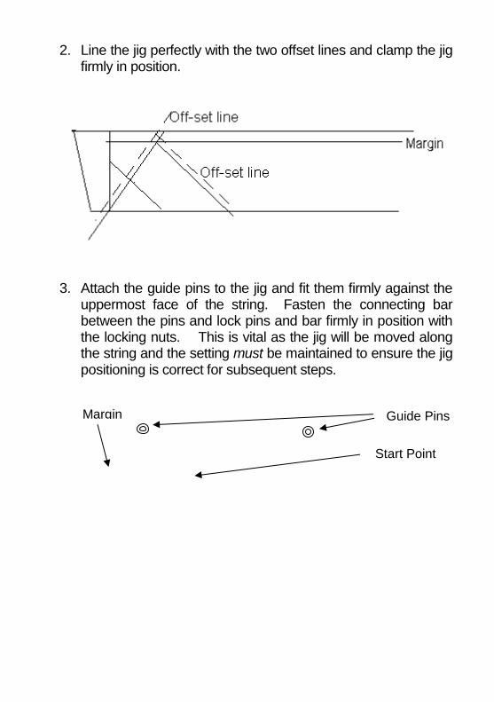
2. Line the jig perfectly with the two offset lines and clamp the jig firmly in position.
3. Attach the guide pins to the jig and fit them firmly against the uppermost face of the string. Fasten the connecting bar between the pins and lock pins and bar firmly in position with the locking nuts. This is vital as the jig will be moved along the string and the setting must be maintained to ensure the jig positioning is correct for subsequent steps.
Start Point
Margin Guide Pins
SAFETY FIRST
1. Make sure all cables are clear of the router.
2. Make sure the work piece is correctly supported.
3. Always use protective goggles when using the router.
4. Do not switch router on with blade touching the work piece.
5. Never remove the router from the jig when it is switched on.
6. Make sure there are no obstructions to the path of the router.
7. READ INSTRUCTIONS CAREFULLY BEFORE STARTING THE WORK.
Router Sub-base Set-up
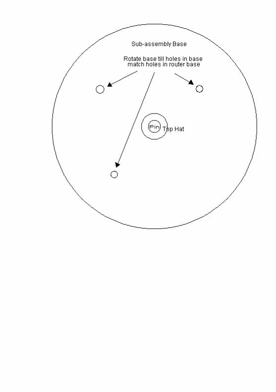
1. Attach the correct Bush to the sub-base assembly (see Table 2). The bush is fitted to the face of the sub-base assembly, which has been counter sunk for the holes. Remove any guide bush from the router.
2. Insert the plastic Pin in the chuck of the router and the plastic Top Hat into the center hole of the sub-base assembly. Fit the Top Hat and sub-base assembly over the Pin then rotate the sub-base assembly until holes in the sub-base assembly and the threaded holes in the router base align. See Page 8 for drawing and bolt information.
3. Select the bolts that match the threaded holes in the router base and screw these firmly into the router base. Do not over tighten
4. Remove the plastic Pin and Top Hat then attach the correct cutter to the router.
5. Set the plunge depth to 12 mm. Allowing for the 12 mm jig the plunge depth, measured from the sub-base assembly will be 24 mm. This should be checked on the edge of the string.
Routing the String
1. Follow the Safety instructions above. 2. Cut out the tread and the riser by starting at the bottom edge
of the string. Always enter and exit at the back of the string with the cutter set at the appropriate depth.
3. Make sure when cutting out the tread that the correct bush is on the leading edge of the router. The edge of the bush should be held to the edge of the jig to achieve the correct width of cut out.
4. When the first tread and riser have been cut out, before the jig is unclamped, put a mark the margin line on the right hand side of the jig. From this mark, measure along the margin the Pitch Angle Length measured in 3d of the Set Up Measurements section. Mark the margin at this point.
5. Unclamp the jig and slide the jig along the string until the right hand side of the jig matches the second mark on the margin. Clamp the jig in place for the routing of the second tread and riser.
6. Continue above steps until all risers and treads have been recessed.
7. The opposite string is a mirror image of the one just completed. The jig is used with the same settings on the new string so do not loosen or move the pegs. Loosen only the wing nuts holding the connecting bar and remove it. Turn the jig over and replace the connecting bar on the opposite side of the jig and tighten in place.
8. Draw the margin on the new string at the same distance as on the first string. Place the jig on the string. Make sure that the first tread and riser fits the string. No measurements are needed, as the jig will mimic the constructions used on the first string. Proceed in a similar manner to the first string construction using the same Pitch Angle Length.
OPEN STAIR JIG
Setting up the open stair jig follows the same steps as the closed stair jig. A 30mm guide bush is used with a 16mm straight cutter giving the tread with a fixed length of 260mm and thickness of 33mm and a nosing projection of 17mm. The treads should overlay by 15mm, which gives a going of 245mm (260-15) and the gap between a tread and the base of the next riser must be no greater than 100mm to ensure a child’s head will not pass through. These measurements should be kept in mind when moving the jig along the string. The off set measurement for the open stair jig is 7mm.
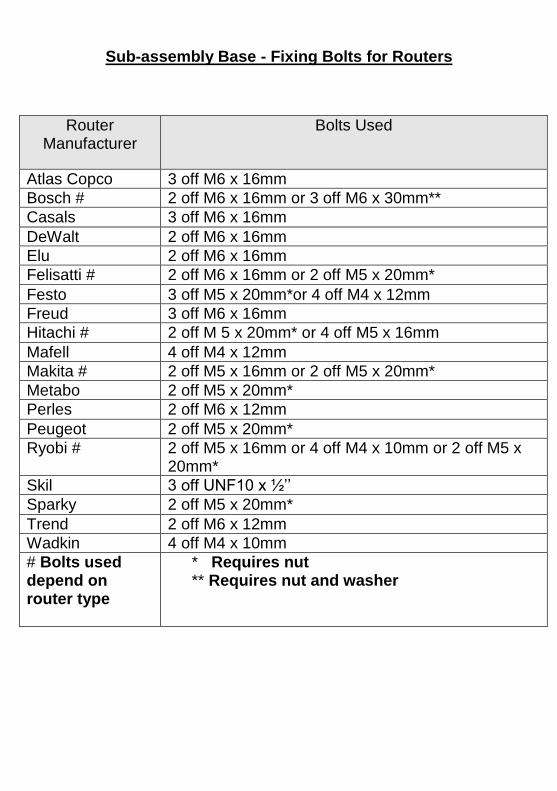
Sub-assembly Base - Fixing Bolts for Routers
Router Manufacturer
Bolts Used
Atlas Copco 3 off M6 x 16mm
Bosch # 2 off M6 x 16mm or 3 off M6 x 30mm**
Casals 3 off M6 x 16mm
DeWalt 2 off M6 x 16mm
Elu 2 off M6 x 16mm
Felisatti # 2 off M6 x 16mm or 2 off M5 x 20mm*
Festo 3 off M5 x 20mm*or 4 off M4 x 12mm
Freud 3 off M6 x 16mm
Hitachi # 2 off M 5 x 20mm* or 4 off M5 x 16mm
Mafell 4 off M4 x 12mm
Makita # 2 off M5 x 16mm or 2 off M5 x 20mm*
Metabo 2 off M5 x 20mm*
Perles 2 off M6 x 12mm
Peugeot 2 off M5 x 20mm*
Ryobi # 2 off M5 x 16mm or 4 off M4 x 10mm or 2 off M5 x 20mm*
Skil 3 off UNF10 x ½’’
Sparky 2 off M5 x 20mm*
Trend 2 off M6 x 12mm
Wadkin 4 off M4 x 10mm
# Bolts used depend on router type
* Requires nut ** Requires nut and washer