Embed Size (px)
Citation preview
An Approved Continuing Education Provider
PDH Course E427 (1 PDH)
Standard AC System Voltages
(600 V and Less)
David A. Snyder, PE
2014
PDH Online | PDH Center
5272 Meadow Estates Drive
Fairfax, VA 22030-6658
Phone & Fax: 703-988-0088
www.PDHonline.org
www.PDHcenter.com
www.PDHcenter.com PDH Course E427 www.PDHonline.org
© 2014 David A. Snyder Page 2 of 14
Standard AC System Voltages (600 V and Less)
David A. Snyder, PE
Table of Contents
Introduction ........................................................................................................................................... 2 Table 1 – Voltage Classes ............................................................................................................ 3
Standard AC System Voltages ............................................................................................................. 3
Table 2 – Standard AC System Voltages .................................................................................... 3 Table 3 – Standard Single-Phase and Three-Phase Systems ..................................................... 4 Table 4 – Ratio of Standard Utilization Voltages to System Voltages ..................................... 4
√3 Relationship of Three-Phase Voltages in Four-Wire Systems ..................................................... 5 Figure 1 – 480Y/277V Wye-Delta Voltage Relationship .......................................................... 5 Figure 2 – Wye-Delta Voltage Relationship – Right Triangle Geometry ................................ 6
Figure 3 – 208Y/120V Wye-Delta Voltage Relationship .......................................................... 7 Standard Transformer Secondary Connections .................................................................................. 7
Figure 4 – Transformer Secondary Connections to Supply the System Voltages ................... 8
Figure 4(a) – Single-Phase, Two-Wire ........................................................................................... 9 Figure 4(b) – Single-Phase, Three-Wire ......................................................................................... 9 Figure 4(c) – Three-Phase, Three-Wire .......................................................................................... 9
Figure 4(d) – Three-Phase, Three-Wire, Closed-Delta .................................................................. 9 Figure 4(e) – Three-Phase, Three-Wire, Open-Delta ..................................................................... 9 Figure 4(f) – Three-Phase, Four-Wire, Grounded Wye ............................................................... 10
Figure 4(g) – Three-Phase, Four-Wire, Closed-Delta, Grounded Center Tap ........................... 10 Figure 5 – 240/120V, 3Φ/4W Voltage Relationships .............................................................. 10
Figure 4(h) – Three-Phase, Four-Wire, Open-Delta, Grounded Center Tap .............................. 11
Three Ways to Provide 120 VAC Power .......................................................................................... 12 Figure 6 – Three Ways to Provide 120 VAC Power ................................................................ 12
In Closing ............................................................................................................................................ 13
Abbreviations ...................................................................................................................................... 13 Additional Reading ............................................................................................................................. 13
Introduction
There are many different voltage standards for AC systems throughout the world as listed at this
link: http://en.wikipedia.org/wiki/Mains_electricity_by_country. This course discusses standard
AC system voltages that are available in the United States of America, as described in Table 1 of
ANSI C84.1-2011. An additional voltage, 600Y/347V, is included because is it listed in
220.5(A) of the NEC.
When you ask, ‘What is considered low voltage and what is considered high voltage?’ you will
probably get different answers, depending on whom you ask. Some people might consider 24 V
to be low voltage while 120 V as high voltage, based on their perspective. Table 1 below is
based on Section 3 System voltage classes, from ANSI C84.1:
www.PDHcenter.com PDH Course E427 www.PDHonline.org
© 2014 David A. Snyder Page 3 of 14
Voltage Class Examples
1,000 V or less Low Voltage (LV) 120V; 208V; 240V; 277V; 480V; 600V
Greater than 1,000 V and
Less than 100 kV
Medium Voltage (MV) 2,400V; 4,160V; 12,470V;
13,800V; 69,000V
Greater than or Equal to 100 kV
and Less than or Equal to 230 kV
High Voltage (HV) 115KV; 138KV; 230KV
Greater than 230 kV and
Less than 1,000 kV
Extra-High Voltage (EHV) 345KV; 500KV; 765KV
Equal to or
Greater than 1,000 kV
Ultra-High Voltage (UHV) 1,000KV; 1,500KV
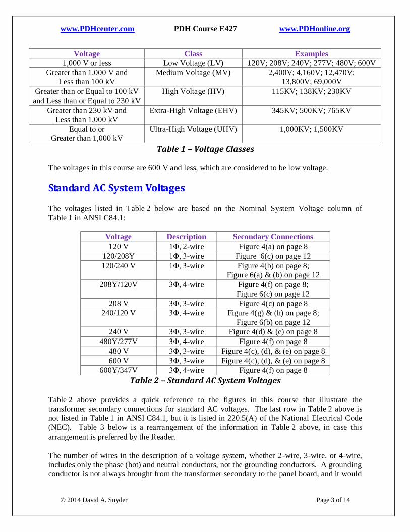
Table 1 – Voltage Classes
The voltages in this course are 600 V and less, which are considered to be low voltage.
Standard AC System Voltages
The voltages listed in Table 2 below are based on the Nominal System Voltage column of
Table 1 in ANSI C84.1:
Voltage Description Secondary Connections
120 V 1Φ, 2-wire Figure 4(a) on page 8
120/208Y 1Φ, 3-wire Figure 6(c) on page 12
120/240 V 1Φ, 3-wire Figure 4(b) on page 8;
Figure 6(a) & (b) on page 12
208Y/120V 3Φ, 4-wire Figure 4(f) on page 8;
Figure 6(c) on page 12
208 V 3Φ, 3-wire Figure 4(c) on page 8
240/120 V 3Φ, 4-wire Figure 4(g) & (h) on page 8;
Figure 6(b) on page 12
240 V 3Φ, 3-wire Figure 4(d) & (e) on page 8
480Y/277V 3Φ, 4-wire Figure 4(f) on page 8
480 V 3Φ, 3-wire Figure 4(c), (d), & (e) on page 8
600 V 3Φ, 3-wire Figure 4(c), (d), & (e) on page 8
600Y/347V 3Φ, 4-wire Figure 4(f) on page 8
Table 2 – Standard AC System Voltages
Table 2 above provides a quick reference to the figures in this course that illustrate the
transformer secondary connections for standard AC voltages. The last row in Table 2 above is
not listed in Table 1 in ANSI C84.1, but it is listed in 220.5(A) of the National Electrical Code
(NEC). Table 3 below is a rearrangement of the information in Table 2 above, in case this
arrangement is preferred by the Reader.
The number of wires in the description of a voltage system, whether 2-wire, 3-wire, or 4-wire,
includes only the phase (hot) and neutral conductors, not the grounding conductors. A grounding
conductor is not always brought from the transformer secondary to the panel board, and it would
www.PDHcenter.com PDH Course E427 www.PDHonline.org
© 2014 David A. Snyder Page 4 of 14
have no bearing on the description of the voltage, whether it is present or not. If a neutral
conductor is brought from the transformer secondary to the panel board, however, it is counted
and determines the description of the voltage.
Single-Phase Systems
Two-Wire 120 V Figure 4(a) on page 8
Three-Wire 120/208Y Figure 6(c) on page 12
Three-Wire 120/240 V Figure 4(b) on page 8;
Figure 6(a) & (b) on page 12
Three-Phase, Three-Wire Systems
Wye 208 V; 480 V; 600 V Figure 4(c) on page 8
Delta 240 V; 480 V; 600 V Figure 4(d) on page 8
Open Delta 240 V; 480 ; 600 V Figure 4(e) on page 8
Three-Phase, Four-Wire Systems
Wye 208Y/120V; 480Y/277V; 600Y/347V Figure 4(f) on page 8
Delta 240/120 V Figure 4(g) on page 8;
Figure 6(b) on page 12
Open Delta 240/120 V Figure 4(h) on page 8
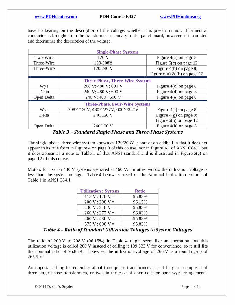
Table 3 – Standard Single-Phase and Three-Phase Systems
The single-phase, three-wire system known as 120/208Y is sort of an oddball in that it does not
appear in its true form in Figure 4 on page 8 of this course, nor in Figure A1 of ANSI C84.1, but
it does appear as a note to Table 1 of that ANSI standard and is illustrated in Figure 6(c) on
page 12 of this course.
Motors for use on 480 V systems are rated at 460 V. In other words, the utilization voltage is
less than the system voltage. Table 4 below is based on the Nominal Utilization column of
Table 1 in ANSI C84.1.
Utilization : System Ratio
115 V : 120 V = 95.83%
200 V : 208 V = 96.15%
230 V : 240 V = 95.83%
266 V : 277 V = 96.03%
460 V : 480 V = 95.83%
575 V : 600 V = 95.83%
Table 4 – Ratio of Standard Utilization Voltages to System Voltages
The ratio of 200 V to 208 V (96.15%) in Table 4 might seem like an aberration, but this
utilization voltage is called 200 V instead of calling it 199.333 V for convenience, so it still fits
the nominal ratio of 95.83%. Likewise, the utilization voltage of 266 V is a rounding-up of
265.5 V.
An important thing to remember about three-phase transformers is that they are composed of
three single-phase transformers, or two, in the case of open-delta or open-wye arrangements.
www.PDHcenter.com PDH Course E427 www.PDHonline.org
© 2014 David A. Snyder Page 5 of 14
This concept is easy to recognize in pole-mounted transformer banks, where the quantity of
single-phase transformers is self-evident, but is not so obvious in pad-mounted or enclosed three-
phase transformers.
What is the relationship between the two voltages in a 480Y/277V system? The line-to-line
voltage is 480 V and the line-to-neutral voltage is 277 V. Why is that? Likewise, how are the
three-phase voltages related in a 208Y/120V system and in a 600Y/347V system?
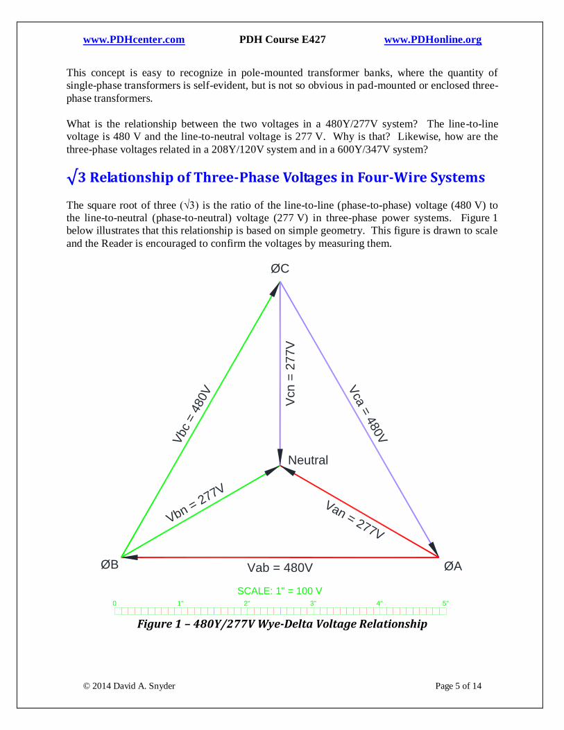
√3 Relationship of Three-Phase Voltages in Four-Wire Systems
The square root of three (√3) is the ratio of the line-to-line (phase-to-phase) voltage (480 V) to
the line-to-neutral (phase-to-neutral) voltage (277 V) in three-phase power systems. Figure 1
below illustrates that this relationship is based on simple geometry. This figure is drawn to scale
and the Reader is encouraged to confirm the voltages by measuring them.
1 2 3 4 5 6 70
Wye-Delta Voltage Relationships
Figure xyz04
1" 2" 3" 4" 5"0
Vab = 480V
Vca
= 4
80V
Vbc
= 4
80V
Van = 277V
Vcn
= 2
77V
Vbn = 277V
ØB ØA
ØC
Neutral
SCALE: 1" = 100 V
Figure 1 – 480Y/277V Wye-Delta Voltage Relationship
www.PDHcenter.com PDH Course E427 www.PDHonline.org
© 2014 David A. Snyder Page 6 of 14
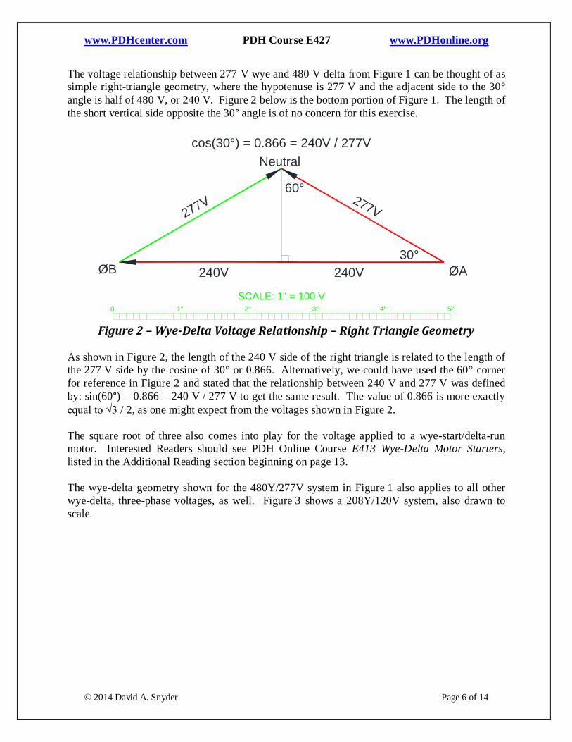
The voltage relationship between 277 V wye and 480 V delta from Figure 1 can be thought of as
simple right-triangle geometry, where the hypotenuse is 277 V and the adjacent side to the 30°
angle is half of 480 V, or 240 V. Figure 2 below is the bottom portion of Figure 1. The length of
the short vertical side opposite the 30° angle is of no concern for this exercise.
1 2 3 4 5 6 70
Wye-Delta Voltage Relationships - Right Trangles
Figure xyz05
240V
277V277V
240V
60°
30°
cos(30°) = 0.866 = 240V / 277V
ØB ØA
1" 2" 3" 4" 5"0
Neutral
SCALE: 1" = 100 V
Figure 2 – Wye-Delta Voltage Relationship – Right Triangle Geometry
As shown in Figure 2, the length of the 240 V side of the right triangle is related to the length of
the 277 V side by the cosine of 30° or 0.866. Alternatively, we could have used the 60° corner
for reference in Figure 2 and stated that the relationship between 240 V and 277 V was defined
by: sin(60°) = 0.866 = 240 V / 277 V to get the same result. The value of 0.866 is more exactly
equal to √3 / 2, as one might expect from the voltages shown in Figure 2.
The square root of three also comes into play for the voltage applied to a wye-start/delta-run
motor. Interested Readers should see PDH Online Course E413 Wye-Delta Motor Starters,
listed in the Additional Reading section beginning on page 13.
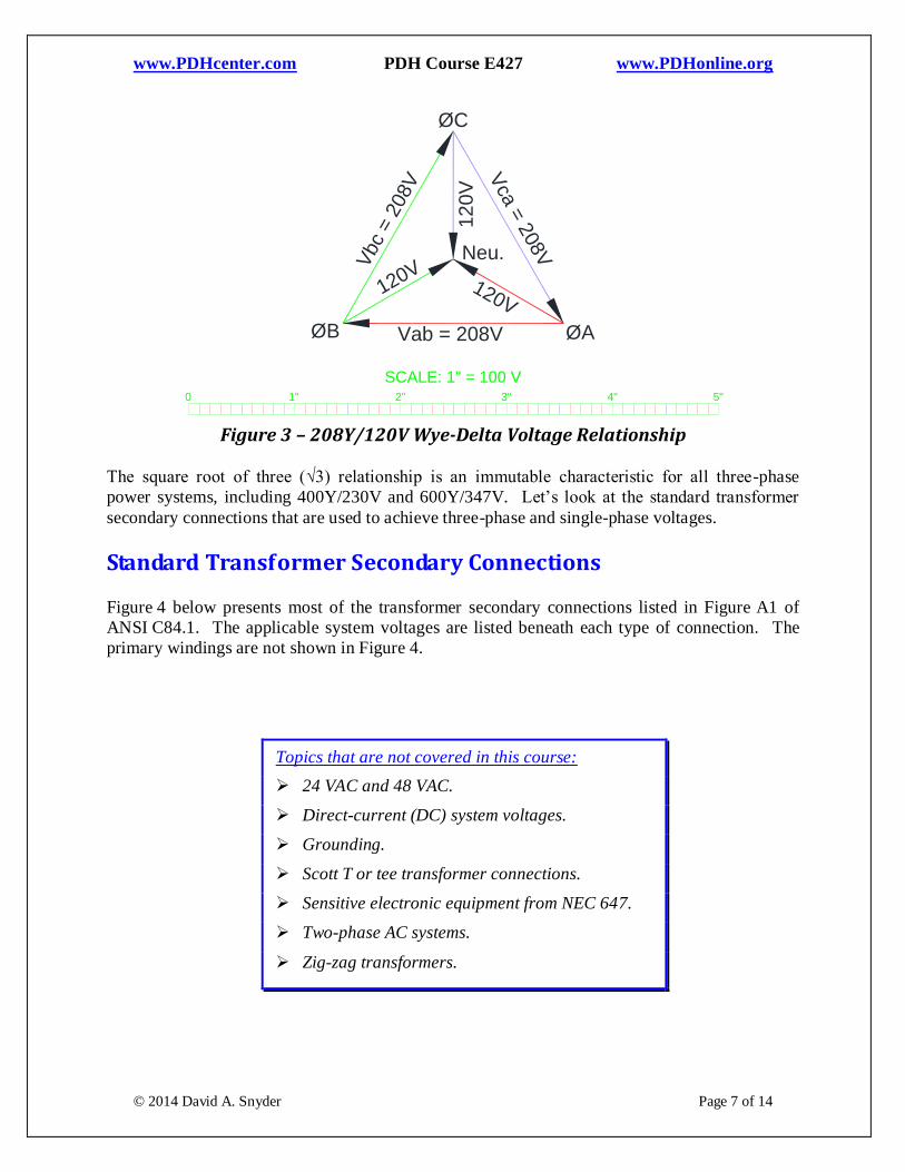
The wye-delta geometry shown for the 480Y/277V system in Figure 1 also applies to all other
wye-delta, three-phase voltages, as well. Figure 3 shows a 208Y/120V system, also drawn to
scale.
www.PDHcenter.com PDH Course E427 www.PDHonline.org
© 2014 David A. Snyder Page 7 of 14
1 2 3 4 5 6 70
208Y/120V Voltage Relationships
Figure xyz06
1" 2" 3" 4" 5"0
Vab = 208V
Vca
= 2
08V
Vbc
= 2
08V
120V
12
0V
120V
ØB ØA
ØC
Neu.
SCALE: 1" = 100 V
Figure 3 – 208Y/120V Wye-Delta Voltage Relationship
The square root of three (√3) relationship is an immutable characteristic for all three-phase
power systems, including 400Y/230V and 600Y/347V. Let’s look at the standard transformer
secondary connections that are used to achieve three-phase and single-phase voltages.
Standard Transformer Secondary Connections
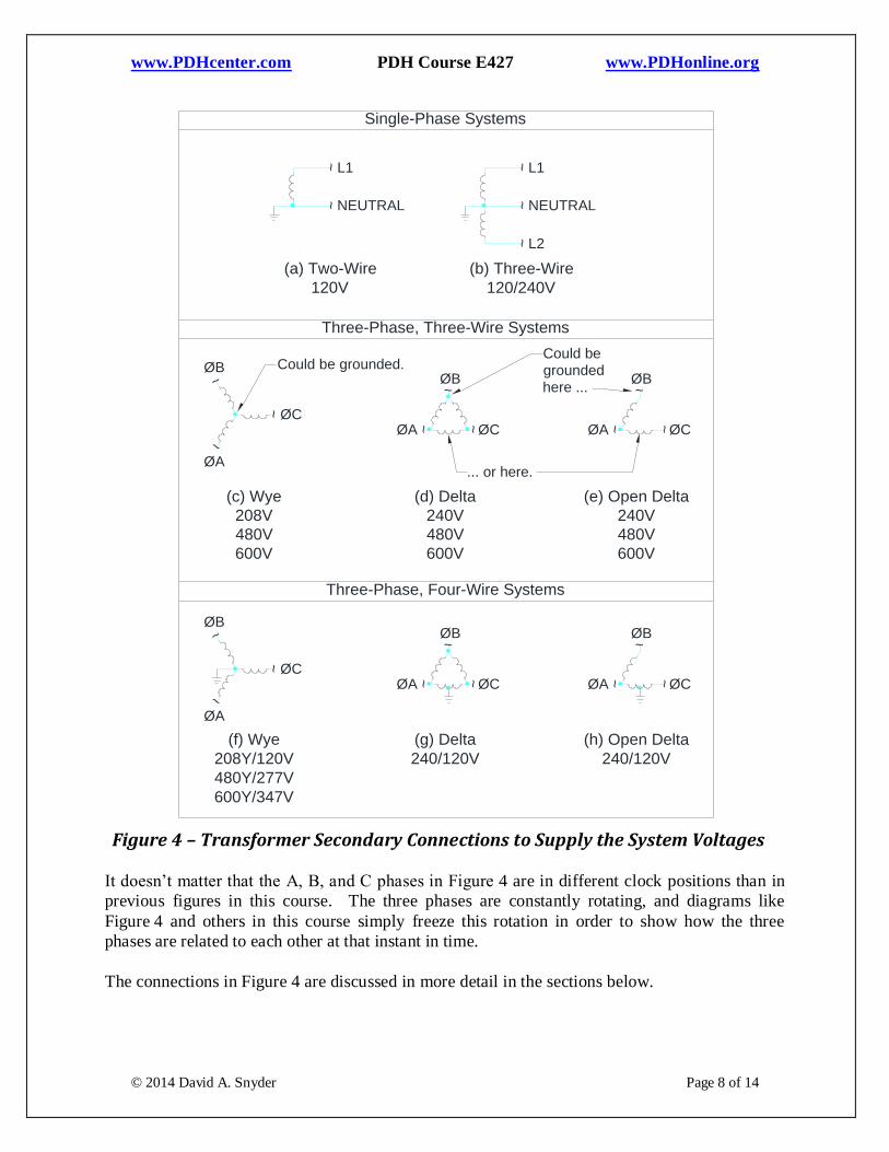
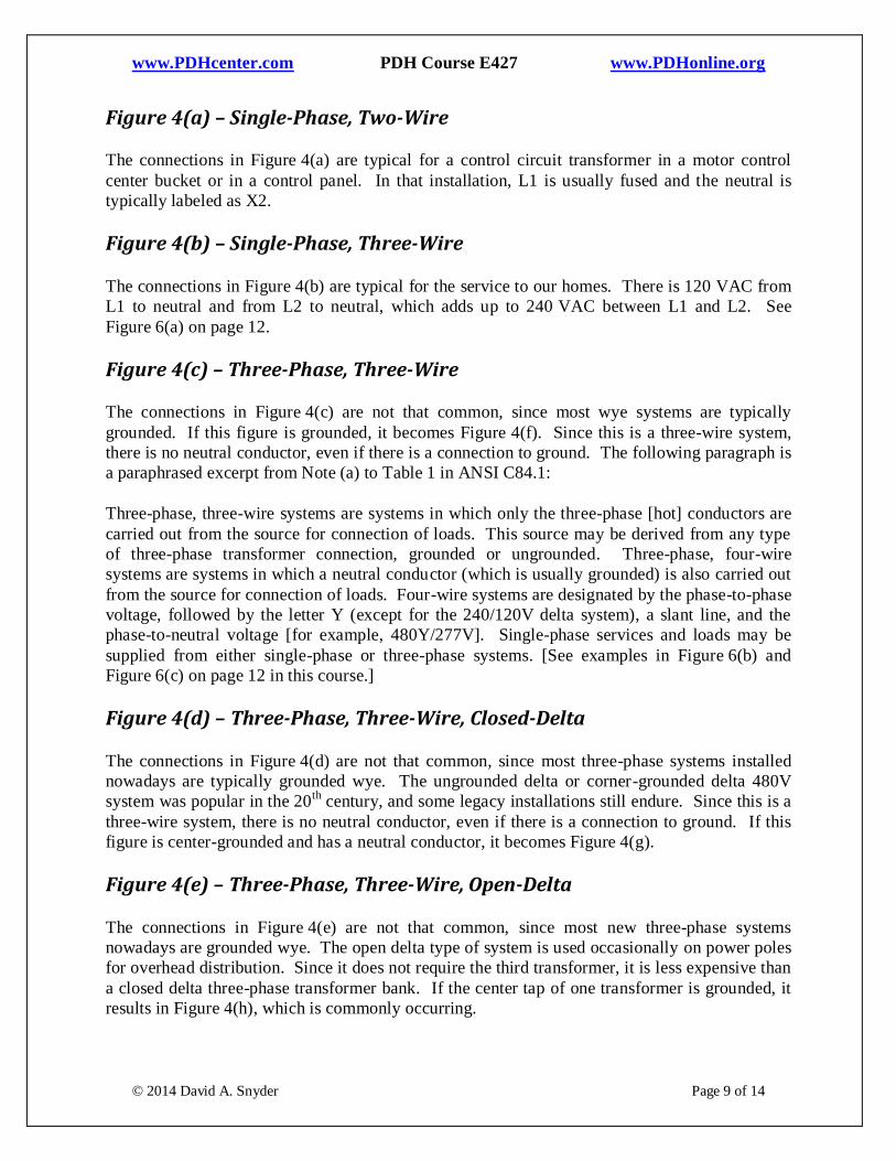
Figure 4 below presents most of the transformer secondary connections listed in Figure A1 of
ANSI C84.1. The applicable system voltages are listed beneath each type of connection. The
primary windings are not shown in Figure 4.
Topics that are not covered in this course:
24 VAC and 48 VAC.
Direct-current (DC) system voltages.
Grounding.
Scott T or tee transformer connections.
Sensitive electronic equipment from NEC 647.
Two-phase AC systems.
Zig-zag transformers.
www.PDHcenter.com PDH Course E427 www.PDHonline.org
© 2014 David A. Snyder Page 8 of 14
Figure 4 – Transformer Secondary Connections to Supply the System Voltages
It doesn’t matter that the A, B, and C phases in Figure 4 are in different clock positions than in
previous figures in this course. The three phases are constantly rotating, and diagrams like
Figure 4 and others in this course simply freeze this rotation in order to show how the three
phases are related to each other at that instant in time.
The connections in Figure 4 are discussed in more detail in the sections below.
Delta-Connected Three-Lead, Three-Phase Motor
Figure 4 / xyz01
1 2 3 4 5 6 70
NEUTRAL
L1
L2~~
~
NEUTRAL
L1
~~
(b) Three-Wire
120/240V
(a) Two-Wire
120V
Three-Phase, Three-Wire Systems
Single-Phase Systems
(c) Wye
208V
480V
600V
ØB~
ØC~
ØA
~
(d) Delta
240V
480V
600V
(e) Open Delta
240V
480V
600V
ØC
ØB~
~ØA ~ ØC
ØB~
~ØA ~
Three-Phase, Four-Wire Systems
(f) Wye
208Y/120V
480Y/277V
600Y/347V
ØB~
ØC~
ØA
~
(g) Delta
240/120V
(h) Open Delta
240/120V
ØC
ØB~
~ØA ~ ØC
ØB~
~ØA ~
Could be grounded.
... or here.
Could begrounded
here ...
www.PDHcenter.com PDH Course E427 www.PDHonline.org
© 2014 David A. Snyder Page 9 of 14
Figure 4(a) – Single-Phase, Two-Wire
The connections in Figure 4(a) are typical for a control circuit transformer in a motor control
center bucket or in a control panel. In that installation, L1 is usually fused and the neutral is
typically labeled as X2.
Figure 4(b) – Single-Phase, Three-Wire
The connections in Figure 4(b) are typical for the service to our homes. There is 120 VAC from
L1 to neutral and from L2 to neutral, which adds up to 240 VAC between L1 and L2. See
Figure 6(a) on page 12.
Figure 4(c) – Three-Phase, Three-Wire
The connections in Figure 4(c) are not that common, since most wye systems are typically
grounded. If this figure is grounded, it becomes Figure 4(f). Since this is a three-wire system,
there is no neutral conductor, even if there is a connection to ground. The following paragraph is
a paraphrased excerpt from Note (a) to Table 1 in ANSI C84.1:
Three-phase, three-wire systems are systems in which only the three-phase [hot] conductors are
carried out from the source for connection of loads. This source may be derived from any type
of three-phase transformer connection, grounded or ungrounded. Three-phase, four-wire
systems are systems in which a neutral conductor (which is usually grounded) is also carried out
from the source for connection of loads. Four-wire systems are designated by the phase-to-phase
voltage, followed by the letter Y (except for the 240/120V delta system), a slant line, and the
phase-to-neutral voltage [for example, 480Y/277V]. Single-phase services and loads may be
supplied from either single-phase or three-phase systems. [See examples in Figure 6(b) and
Figure 6(c) on page 12 in this course.]
Figure 4(d) – Three-Phase, Three-Wire, Closed-Delta
The connections in Figure 4(d) are not that common, since most three-phase systems installed
nowadays are typically grounded wye. The ungrounded delta or corner-grounded delta 480V
system was popular in the 20th
century, and some legacy installations still endure. Since this is a
three-wire system, there is no neutral conductor, even if there is a connection to ground. If this
figure is center-grounded and has a neutral conductor, it becomes Figure 4(g).
Figure 4(e) – Three-Phase, Three-Wire, Open-Delta
The connections in Figure 4(e) are not that common, since most new three-phase systems
nowadays are grounded wye. The open delta type of system is used occasionally on power poles
for overhead distribution. Since it does not require the third transformer, it is less expensive than
a closed delta three-phase transformer bank. If the center tap of one transformer is grounded, it
results in Figure 4(h), which is commonly occurring.
www.PDHcenter.com PDH Course E427 www.PDHonline.org
© 2014 David A. Snyder Page 10 of 14
The total KVA of the two-transformer open-delta transformer bank is less than one might expect
when removing one of the three transformers to make the open delta. If a transformer is
removed from a 30 KVA closed-delta transformer bank that had three 10 KVA transformers, the
new rating of the two-transformer bank would be 58% of 30 KVA or 17.3 KVA. This is
discussed in more detail in PDH Online Course E431 The Square Root of Three (√3) in
Electrical Calculations, listed in the Additional Reading section beginning on page 13.
Figure 4(f) – Three-Phase, Four-Wire, Grounded Wye
The connections in Figure 4(f) are very popular for commercial and industrial power systems,
especially 480Y/277V and 208Y/102V. Those voltages are illustrated in Figure 1 on page 5 and
Figure 3 on page 7. This connection provides both three-phase (480 V and 208 V) and single-
phase (277 V and 120 V) power.
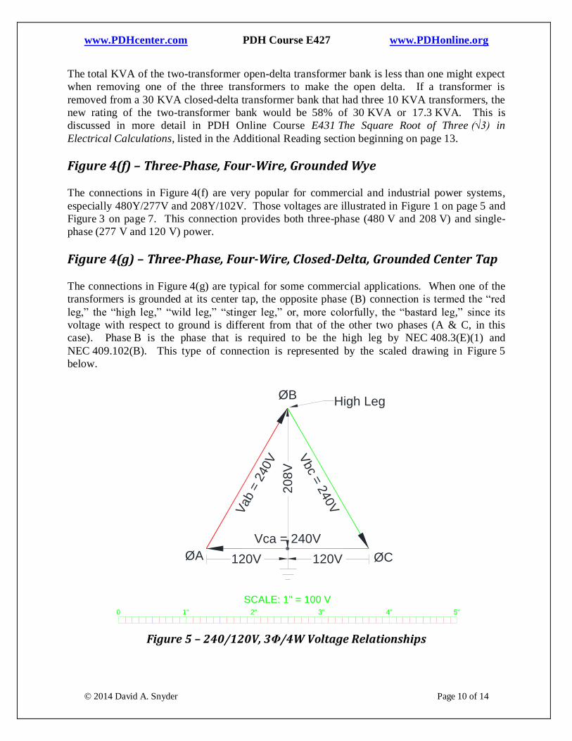
Figure 4(g) – Three-Phase, Four-Wire, Closed-Delta, Grounded Center Tap
The connections in Figure 4(g) are typical for some commercial applications. When one of the
transformers is grounded at its center tap, the opposite phase (B) connection is termed the “red
leg,” the “high leg,” “wild leg,” “stinger leg,” or, more colorfully, the “bastard leg,” since its
voltage with respect to ground is different from that of the other two phases (A & C, in this
case). Phase B is the phase that is required to be the high leg by NEC 408.3(E)(1) and
NEC 409.102(B). This type of connection is represented by the scaled drawing in Figure 5
below.
Center-Grounded 120/240V
Figure 5 / xyz07
1 2 3 4 5 6 70
1" 2" 3" 4" 5"0
Vca = 240V
Vbc =
240V
Vab =
240V
ØA ØC
ØB
SCALE: 1" = 100 V
120V120V
20
8V
High Leg
Figure 5 – 240/120V, 3Φ/4W Voltage Relationships
www.PDHcenter.com PDH Course E427 www.PDHonline.org
© 2014 David A. Snyder Page 11 of 14
As previously stated, the B phase in this type of connection is called the “high leg” because its
potential is higher above the ground reference than the other two phases (A & C). Figure 5
above demonstrates that the voltage from A phase to ground is 120 V, while the voltage from
C phase to ground is also 120 V, but 180° out of phase with A phase. The voltage from A to C is
240 V, which is why this is called a 240/120V system.
The voltage from B phase to ground is 208 V, which can be measured readily in Figure 5. That
is why this phase is called the “high leg.” It is also known as the “red leg” because it is typically
required to be an orange conductor or marked with paint or tape as an orange conductor to
differentiate it from the other two phase conductors [NEC 110.15]. See, also, the high-leg
identification requirements of NEC 408.3(F)(1) for switchboards, switchgear, and panelboards.
This type of transformer is available as an enclosed three-phase transformer, but an important
thing to note about this type of transformer secondary connection is that the line-to-neutral
voltage (120 VAC) loads is often limited to only 5% of the total KVA rating of the three-phase
transformer. In other words, if the enclosed transformer is rated 30 KVA, only 5% or 1.5 KVA
can be used for 120 VAC loads. The enclosed transformer cut-sheet should have all pertinent
information regarding this rating. This is different from the closed-delta and open-delta
arrangement realized with banks of individual transformers, since the utility will sometimes
provide a larger transformer (located opposite of the high leg) for the single-phase loads.
One might wonder, if we can ground the center tap of the single-phase transformer between
Phase A and Phase C, why couldn’t we do the same thing to the single-phase transformer
between Phase B and Phase C and the single-phase transformer between Phase B and Phase A,
thus providing three sources for 120 VAC from the same three-phase transformer bank? We
won’t get into any mathematics, but let’s picture this in our minds.
If a voltage system is not tied to ground, it is not possible to say what the voltage at any point in
that system is with reference to ground. If, on the other hand, one point on the voltage system is
permanently tied to ground, such as the center-tap in Figure 4(g), we can be assured that, under
normal conditions, the voltage from Phase A to ground will be 120 VAC, the voltage from
Phase C to ground will always be 120 VAC, and the voltage from Phase B to ground will always
be 208 VAC to ground. It is okay to tie one corner or one center-tap of the secondary of a three-
phase transformer or transformer bank to ground at one place only, since the voltage vectors will
still be free to rotate around that neutral point. If an attempt is made to ground the voltage
system at a second point, it would be the same as installing a short-circuit between those two
grounded points, since both points would be at the same potential. This, obviously, is not an
acceptable situation.
Figure 4(h) – Three-Phase, Four-Wire, Open-Delta, Grounded Center Tap
The connections in Figure 4(h) are typical for some business and commercial installations and
only require two transformers, as discussed for Figure 4(e) above. The transformer that is
center-tapped is typically grounded at that point in order to provide 120/240V single-phase, as
well as 240V, three-phase. The center-tapped transformer is often larger than the other one,
since the center-tapped transformer provides power for lighting, receptacles, and other single-
www.PDHcenter.com PDH Course E427 www.PDHonline.org
© 2014 David A. Snyder Page 12 of 14
phase loads, in addition to three-phase loads. Whether the center-tapped transformer is larger or
not, it is often called the “lighter,” since it powers the lights and other single-phase loads. If one
of the transformers is smaller, it is sometimes called the “power” or “kicker” transformer. If the
three-phase load increases after installing this type of transformer bank, a third transformer can
be added later to provide additional capacity, resulting in Figure 4(g).
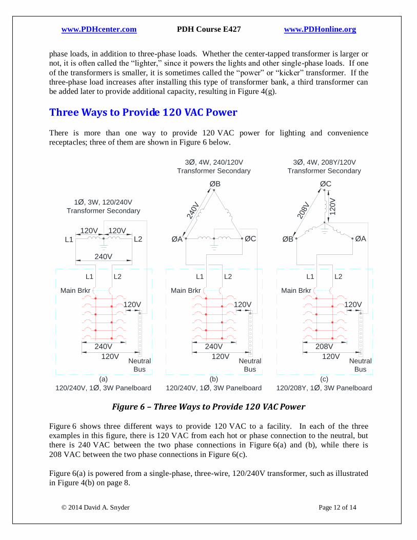
Three Ways to Provide 120 VAC Power
There is more than one way to provide 120 VAC power for lighting and convenience
receptacles; three of them are shown in Figure 6 below.
Three Different Ways to Obtain 120VAC Power
Figure 6 / xyz02
1 2 3 4 5 6 70
L2L1
Neutral
Bus
1Ø, 3W, 120/240V
Transformer Secondary
(a)
120/240V, 1Ø, 3W Panelboard
Main Brkr
L2L1
Neutral
Bus
3Ø, 4W, 240/120V
Transformer Secondary
(b)
120/240V, 1Ø, 3W Panelboard
Main Brkr
ØCØA
ØB
L2L1
240V
120V
120V
240V
120V
120V
L2L1
Neutral
Bus
3Ø, 4W, 208Y/120V
Transformer Secondary
(c)
120/208Y, 1Ø, 3W Panelboard
Main Brkr
ØAØB
ØC
208V
120V
120V
120V 120V
240V
208V
12
0V
240V
Figure 6 – Three Ways to Provide 120 VAC Power
Figure 6 shows three different ways to provide 120 VAC to a facility. In each of the three
examples in this figure, there is 120 VAC from each hot or phase connection to the neutral, but
there is 240 VAC between the two phase connections in Figure 6(a) and (b), while there is
208 VAC between the two phase connections in Figure 6(c).
Figure 6(a) is powered from a single-phase, three-wire, 120/240V transformer, such as illustrated
in Figure 4(b) on page 8.
www.PDHcenter.com PDH Course E427 www.PDHonline.org
© 2014 David A. Snyder Page 13 of 14
Figure 6(b) is powered from the center-tapped portion of a three-phase, four-wire, 240/120V
transformer, such as illustrated in Figure 4(g) on page 8, but it could also be accomplished with
the open-delta secondary arrangement shown in Figure 4(h).
Figure 6(c) is powered from two secondary phase connections and a neutral connection on a
three-phase, four-wire, 208Y/120V transformer, such as illustrated in Figure 4(f) on page 8. No
connection is made to Phase C in Figure 6(c). This could be powered by an open-wye
transformer bank, which isn’t shown in Figure 4, but can easily be pictured as not having a
Phase C winding. There is a Note (d) to Table 1 in ANSI C84.1 that addresses this specific
voltage system by saying, “A modification of this three-phase, four-wire system [Figure 4(f)] is
available as a 120/208Y-volt service for single-phase, three-wire, open-wye applications.”
In Closing
In this course, we have reviewed the standard AC system voltages that are available in the
United States. We have also seen that the phase-to-phase and phase-to-neutral voltages are
related to each other by the square root of three (√3) in three-phase AC systems. All of the
voltage systems, in fact, can be drawn to scale and measured to prove the voltage relationship of
various connection points to each other.
Whether or not a three-phase system is three-wire or four-wire depends on whether or not a
neutral conductor is brought out from the voltage source to supply other systems or loads. It is
possible that a three-phase service could be grounded without installing a neutral conductor.
It is hoped that this course has either served as a refresher or will assist the Reader in easily
recognizing the transformer arrangements that are implied when he or she hears the term
‘480Y/208V’ or ‘120/240V, 3-wire.’
Abbreviations
A Amp or Amps
AC Alternating Current
ANSI American National Standards Institute, Inc.
Hz Hertz or cycles-per-second
N.A. Not Applicable
NEC National Electrical Code, 2014 Edition
NEMA National Electrical Manufacturers Association
V Volt or Volts
VAC Volts Alternating Current
Additional Reading
ANSI C84.1-2011 American National Standard Electric Power Systems and Equipment –
Voltage Ratings (60 Hertz) at www.nema.org
www.PDHcenter.com PDH Course E427 www.PDHonline.org
© 2014 David A. Snyder Page 14 of 14
Mains electricity by country at http://en.wikipedia.org/wiki/Mains_electricity_by_country
NFPA 70 National Electrical Code, (NEC) 2014 Edition at www.nfpa.org
PDH Online course E413 Wye-Delta Motor Starters at www.pdhonline.org
PDH Online course E431 The Square Root of Three (√3) in Electrical Calculations at
www.pdhonline.org
— · — — — — — · · — · · · · · — · · · — · · — — · — — — — · — · — · · · — · — · ·