Embed Size (px)
Citation preview
2016
THIS DOCUMENT IS FORMATTED FOR TWO‐SIDED PRINTING
Acknowledgements FACILITY DESIGN STANDARDS & PROCEDURES GUIDELINE
Page i
UAA Facilities & Campus Services
Chris Turletes, Associate Vice Chancellor
UAA Facilities Planning & Construction
John Faunce, Director
John Hanson, Project Manager
Cory Fischer, Assistant Project Manager
UAA Facilities Maintenance & Operations
Tom Sternberg, Director
Glenn E. Brown, Associate Director
Consultant Team
Livingston Slone, Inc.
Spiral Design Elements
AMC Engineers, Inc.
Corvus Design

FACILITY DESIGN STANDARDS & PROCEDURES GUIDELINE
Page ii
THIS PAGE INTENTIONALLY LEFT BLANK
Table of Contents FACILITY DESIGN STANDARDS & PROCEDURES GUIDELINE
Page iii
Cover
Acknowledgements i
Table of Contents iii
Document Overview vii
Project Administration 1
Project Development 5
General Design Considerations 1
Site Design 7
Exterior Building Design 22
Interior Building Design 25
MEP System Design 35
Division 3 Concrete Exterior Concrete
Division 4 Masonry Exterior Stone Cladding
Division 5 Metals Metal Fastenings & Finishes • Metal Ladders • Metal Railings • Metal Stair Nosings
Table of Contents FACILITY DESIGN STANDARDS & PROCEDURES GUIDELINE
Page iv
Division 6 Wood, Plastics and Composites Rough Carpentry • Finish Carpentry • Architectural Woodwork • Plastic Fabrications • Plastic
Fabrications
Division 7 Thermal and Moisture Protection Damp Proofing and Waterproofing • Thermal Protection • Weather Barriers • Metal Roofing and
Siding • Membrane Roofing • Roof Accessories • Fire and Smoke Protection • Joint Protection.
Division 8 Openings Doors and Frames • Specialty Doors and Frames • Entrances, Storefronts and Curtain Walls •
Windows • Roof Windows and Skylights • Hardware • Glazing
Division 9 Finishes Gypsum Board • Tiling • Ceilings • Flooring • Wall Finishes • Acoustical Treatment • Paintings &
Coatings
Division 10 Specialties Information Specialties • Interior Specialties • Safety Specialties • Storage Specialties
Division 11 Equipment Food Service Equipment • Educational and Scientific Equipment • Collection and Disposal
Equipment
Division 12 Furnishings Window Treatments • Casework • Furnishings and Accessories • Furniture • Site Furnishings
Division 13 Special Construction Vibration and Seismic Control
Division 14 Conveying Equipment Elevators
Division 20 Mechanical Common Work Results • Insulation
Division 22 Plumbing Plumbing Piping • Equipment • Fixtures • Compressed Air, Gas and Vacuum Systems
Division 23 Heating, Ventilating & Air Conditioning Fuel Systems • HVAC Piping and Pumps • Air Distribution • Air Cleaning Devices • Central Heating
Equipment • Central Cooling Equipment • Central HVAC Equipment • Decentralized HVAC
Equipment
Division 25 Integrated Automation Network Equipment • Instrumentation and Terminal Devices • Facility Controls
Table of Contents FACILITY DESIGN STANDARDS & PROCEDURES GUIDELINE
Page v
Division 26 Electrical General Requirements • Wire and Cable • Grounding • Hangers and Supports • Cable Tray •
Raceway and Boxes • Identification • Power Monitoring • Lighting Controls • Transformers •
Switchboards • Panel Boards • Motor Control Centers • Feeder and Plug‐In Busway • Enclosed
Contactors • Wiring Devices • Enclosed Switches and Breakers • Motor Starters and Controllers •
Engine Generators • Static UPS • Automatic Transfer Switches • Interior Lighting • Emergency
Lighting • Exterior Lighting
Division 27 Communications Structured Cabling • Audio‐Video Communications
Division 28 Electronic Safety and Security Access Control • IP Closed Circuit Television • Fire Detection and Alarm
Division 31 Earthwork Site Clearing • Earth Moving • Plant Protection and Salvaging
Division 32 Exterior Improvements Planting General • Planting Soil • Lawns and Grasses • Exterior Plants • Landscape Accessories •
Landscape Maintenance • Irrigation

Table of Contents FACILITY DESIGN STANDARDS & PROCEDURES GUIDELINE
Page vi
THIS PAGE INTENTIONALLY LEFT BLANK
8.29.2016 Document Overview FACILITY DESIGN STANDARDS & PROCEDURES GUIDELINE
Page vii
Overview
Scope & Purpose
The University of Alaska Anchorage Facility Design Standards and Procedures Guideline (“Standards”,
“Document”) is a compilation of procedures, guidelines and technical requirements associated with the
planning, design, and construction of facilities on campus. The Document is the product of the efforts,
expertise and institutional experience of project managers with UAA Facilities Planning and Construction
(FP&C), and UAA Facilities Maintenance and Operations (FMO) personnel. The purpose of the Document is
three‐fold:
1. To aggregate important information necessary for planners and designers.
2. To outline important design considerations and goals for new and renovated facilities.
3. To standardize certain procedures, design elements, and technical components for all new
buildings and renovation projects on campus.
Together with the UAA Campus Master Plan, the Standards ensure that capital projects are planned,
designed, and constructed in accordance with UAA’s strategic goals and vision for the campus.
Use & Organization of Document
The Facility Design Standards and Procedures Guideline is intended to be a reference standard for all new
building and renovation projects on the UAA campus, and hence shall be used by FP&C project managers
and the architectural and engineering (A/E) consultants they hire to provide professional design services.
The Standards are intended to apply to all projects: new construction and renovation of existing facilities.
Certain aspects of the Standards are informational in nature and/or are intended to guide the design
consideration and decision‐making process; however, most are requirements. Projects seeking departure
from any Standards requirements shall seek formal waiver from the UAA FP&C Director prior to
implementing changes.
The Standards do NOT replace or supersede the responsibilities of the design professional. The burden of
proper design evaluation, analysis, code compliance, life safety, and standard‐of‐care rests solely with the
A/E consultants hired by UAA.
The Document is organized into three sections:
1. Project Procedures and Administration
2. Campus Design Standards
3. Technical Requirements
Document Overview 8.29.2016 FACILITY DESIGN STANDARDS & PROCEDURES GUIDELINE
Page viii
Part 1 is intended to familiarize the A/E consultant with UAA’s procedures for managing and administering
design projects, including the required design approval process the A/E must support. Part 2 summarizes
general requirements and guiding design goals for all campus projects. Part 3 is a compilation of technical
product and component requirements organized by Construction Specification Institute (CSI)
MasterFormat (2004) section.
None of the sections in the Document are exhaustive or all‐encompassing. The content identifies UAA’s
important planning and design priorities it seeks to standardize across all projects. The A/E consultant is
responsible for understanding the intent of the Document and for seeking additional information and
clarification from UAA as necessary to properly perform any planning and design services.
The Standards are a “living document” and will be updated as new requirements materialize and as old
ones become obsolete. In order to be useful, the Standards must be flexible, responding to changes in
policy, industry, technology, and approach. In addition, the Standards scope and content may grow as
UAA becomes more certain about various aspects of design or as new information emerges. The
Standards are part of a broad set of University vision and planning documents, which themselves are
subject to change and growth. This Document must be responsive to changes to these guiding documents
and to the broader campus vision.
Product Specifications
As a state institution, UAA’s projects must comply with state procurement code (Alaska Statute 36.30).
Generally, UAA’s procurement policies require that products and services are competitively selected. Part
3 of this document includes technical requirements for products specified for building projects on the UAA
campus. In certain instances, specific product brands and models are listed, and certain terms may be
applied to product bands and models such as “preferred” or “acceptable.” The intent of the Technical
Requirements is not to limit or pre‐select brands and models, but rather to set a baseline level of quality
required by the University and to provide examples of products that typically have met the baseline level
of quality and have been successfully utilized in prior campus building projects.
Design specifications for future campus projects must meet the intent of both state procurement code as
well as the minimum standards set forth in this document. Products and systems must be available from
multiple sources capable of providing equal or similar quality. The A/E consultant must ensure that any
proprietary products/systems specified have at least two additional similar products/systems which are
acceptable for use in the project, and list those products/systems as acceptable alternatives in the project
specifications. Any deviations from either state procurement code or these design standards must be
approved by the FP&C Director.
8.29.2016 Document Overview FACILITY DESIGN STANDARDS & PROCEDURES GUIDELINE
Page ix
Additional Reference, Policy and Source Documents
University of Alaska Anchorage Strategic Plan 2017: www.uaa.alaska.edu/academics/institutional‐
effectiveness/strategic‐planning.cshtml
University of Alaska Anchorage Campus Master Plan 2013: www.uaa.alaska.edu/about/administrative‐
services/departments/facilities‐campus‐services/facilities‐planning‐construction/master‐
plan/_documents/2013_uaa_campus_master_plan_reduced.pdf
UAA Energy Policy, 2007: www.uaa.alaska.edu/about/administrative‐services/departments/facilities‐
campus‐services/_documents/energy_policy.pdf
UAA Master Utility Plan, 2014
UAA Equipment, Infrastructure, and Wiring Standards, 28 February 2012
University of Alaska Anchorage Unified Exterior Signage Plan, 2006
UAA Interior Sign Guide
UA Statewide Facilities: www.alaska.edu/facilities/
UAA Facilities Planning & Construction: www.uaa.alaska.edu/about/administrative‐
services/departments/facilities‐campus‐services/facilities‐planning‐construction/
UAA Facilities Maintenance & Operations: www.uaa.alaska.edu/about/administrative‐
services/departments/facilities‐campus‐services/maintenance‐operations/index.cshtml
Municipality of Anchorage Title 21: Land Use Planning 2013 (“New Title 21”):
www.muni.org/Departments/OCPD/Planning/Projects/t21/Pages/Title21Rewrite.aspx

Document Overview 8.29.2016 FACILITY DESIGN STANDARDS & PROCEDURES GUIDELINE
Page x
THIS PAGE INTENTIONALLY LEFT BLANK

THIS PAGE INTENTIONALLY LEFT BLANK
8.29.2016 Part 1: Project Procedures & Administration FACILITY DESIGN STANDARDS & PROCEDURES GUIDELINE
Part 1
Page 1
Project Administration
1.01 University Stakeholders
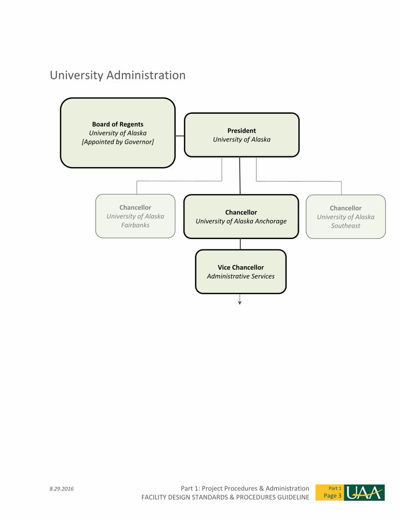
The University of Alaska Anchorage (UAA) is part of the broader University of Alaska (UA) system. The full
organization charts for UA and UAA can be found on the University’s websites. This document includes a
simplified version of the organizational structure to assist Architect/Engineering (A/E) consultant teams in
understanding the ‘chain of command’ and the complexity of the decision making process.
Stakeholders in each project will vary depending on the type and scale of a project. The end user (such as
an Academic Department) is the functional stakeholder with Facility Maintenance and Operations (FMO)
as a parallel primary stakeholder. The A/E project manager is encouraged to discuss the list of
stakeholders with the UAA Facilities Planning and Construction Project Manager (FP&C PM) to determine
when to interface with each of the identified stakeholders. Similar to other large institutions, there are
many processes and procedures that require communication between multiple departments to achieve an
‘agreed’ direction.
1.02 Communications & Documentation
The A/E team project manager’s primary contact is the assigned UAA Facilities Planning and Construction
Project Manager. All project related communication between the A/E team and UAA (or UA) shall be
channeled through the FP&C PM. Any discussions, presentations or meetings with the UAA user group or
other concerned UAA departments shall be coordinated through the FP&C PM. All correspondence,
meetings, or presentations to/with municipal or other permitting agencies, utility providers, community
councils, media or other non UAA entities, shall be coordinated with the UAA FP&C PM.
The A/E team will keep clear and concise records of all project correspondence and make such
correspondence available to the FP&C PM upon request. Meeting minutes will be kept by the A/E team
and copies of all such meeting records shall be distributed by the A/E to the attendees including the FP&C
PM providing an opportunity for review and comment.
Part 1: Project Procedures & Administration 8.29.2016 FACILITY DESIGN STANDARDS & PROCEDURES GUIDELINE
Part 1
Page 2
1.03 Administrative Approval Process
At various stages of the project development UAA is required to receive administrative approval or provide
status reports to the Administration (i.e. Chancellors’ Office, Board of Regents, and UA Statewide). The
timing of these reports is driven by the Board of Regents (BoR) meeting schedule and the Regents’ Policy
Part V – Finance and Business Management, Chapter 05.12 – Capitol Planning and Facilities Management.
When developing the project schedule the A/E project manager should coordinate with the FP&C PM on
when Administrative Reports will require information from the A/E Team and the scope of the material
required.
Project informational packets for the BoR meetings are developed by UAA FP&C and are required to be
submitted 30 calendar days prior to the date of the BoR meeting. The A/E team should have the
requested materials available to FP&C PM at least two weeks ahead of the 30 day submittal deadline or as
directed by the FP&C PM. There are seven project approval and reporting stages listed in the Regents’
Policy as follows:
1. Preliminary Administrative Approval – Authorization to plan a project and to develop a Project
Agreement documenting the programmatic need, scope and estimated cost of the project;
2. Formal Project Approval – Authorization to develop the basic design of the facility or project
through creation of a schematic design;
3. Schematic Design Approval – Authorization to complete the design of the facility or project, to
develop construction documents, and, subject to no material changes, bid and award a contract;
4. Project Change Approval – Authorization to modify the project budget or scope after schematic
design approval;
5. Pre‐Bid Project Report – Report on the results of the final design process;
6. Construction Contract Award Report – Report on the results of the bid process and award; and
7. Final Project Report – Report on wrap‐up of the project.
It is important to note that the BoR Schematic Design Approval (SDA) is authorization to complete the
design, develop final construction drawings, bid, and construct the project. The level of detail required for
the SDA is beyond what a typical 35% level Schematic Design would include. An example would be color,
material, and finish samples for the exterior and interior of the project. The A/E should review the
Regents’ Policy P05.12043. Capitol Project Development: Schematic Design Approval for additional detail
and information on what is expected. Depending on project scope and dollar value the level of detail and
documentation will vary. Confirm the specific project approval requirements with the FP&C PM.
8.29.2016 Part 1: Project Procedures & Administration FACILITY DESIGN STANDARDS & PROCEDURES GUIDELINE
Part 1
Page 3
University Administration
Vice Chancellor Administrative Services
Chancellor University of Alaska Anchorage
President University of Alaska
Board of Regents University of Alaska
[Appointed by Governor]
Chancellor University of Alaska
Fairbanks
Chancellor University of Alaska
Southeast
Part 1: Project Procedures & Administration 8.29.2016 FACILITY DESIGN STANDARDS & PROCEDURES GUIDELINE
Part 1
Page 4
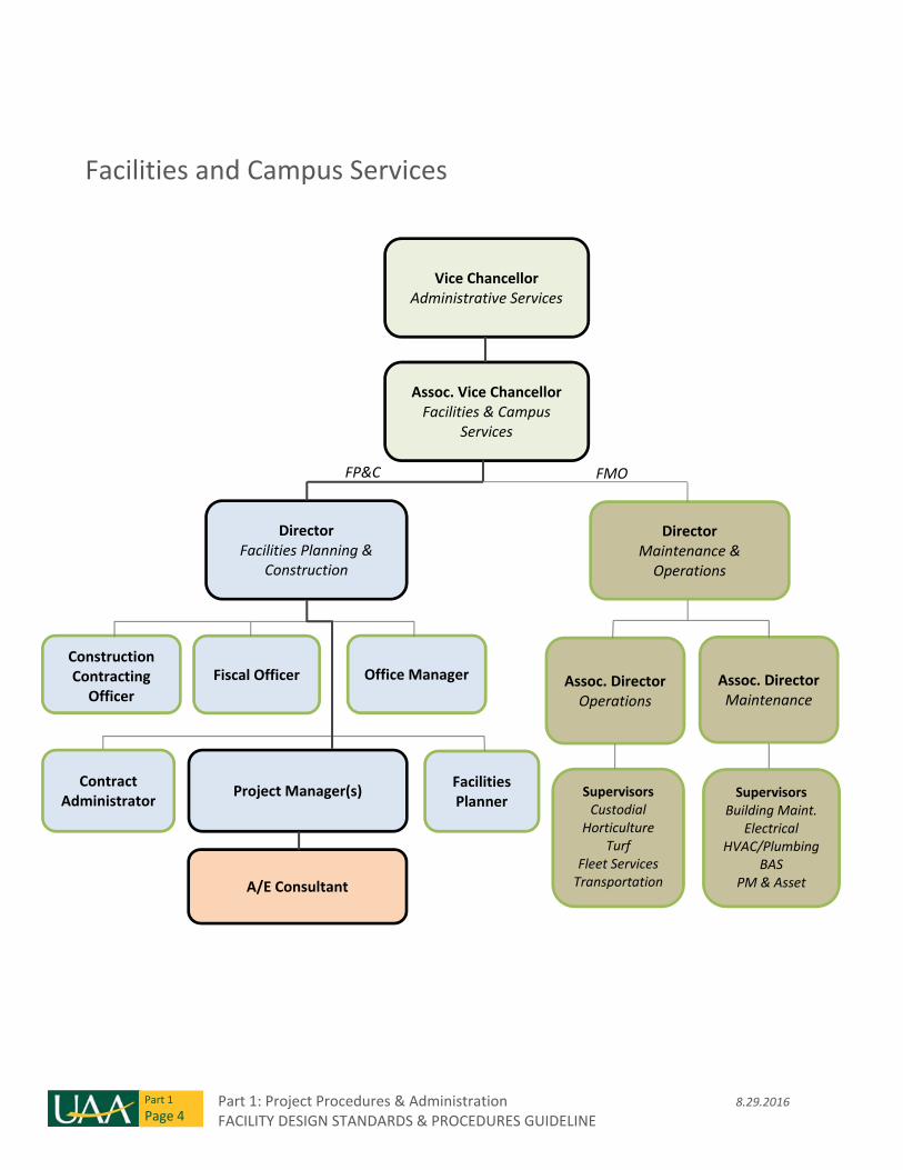
Facilities and Campus Services
Vice Chancellor Administrative Services
Assoc. Vice Chancellor Facilities & Campus
Services
Director Facilities Planning &
Construction
Director Maintenance & Operations
Construction Contracting Officer
Fiscal Officer Office Manager Assoc. Director Operations
Assoc. Director Maintenance
Contract Administrator
Project Manager(s) Facilities Planner
Supervisors Custodial
Horticulture Turf
Fleet Services Transportation A/E Consultant
FP&C FMO
SupervisorsBuilding Maint.
Electrical HVAC/Plumbing
BAS PM & Asset
8.29.2016 Part 1: Project Procedures & Administration FACILITY DESIGN STANDARDS & PROCEDURES GUIDELINE
Part 1
Page 5
1.04 Design Contracts and Invoicing
Typically an RFP for design services will include a draft version of the design contract. UAA will provide an
electronic version of the invoicing spread sheet to be used for monthly invoicing.
1.05 Project Management Software
UAA utilizes project management software from e‐Builder®. The A/E shall coordinate with the FP&C PM to
establish the extent to which e‐Builder shall be used by the A/E for the project.
Project Development
1.06 Facility Functional Programming & Owner’s Project Requirements
On most new projects, the University selects an A/E after receiving preliminary or formal administrative
project approval, but prior to the building programming stage. At this stage, a site may or may not have
been selected for the project. The A/E’s first steps are typically to lead the programming effort and to
assist as needed with identifying and evaluating the appropriate site(s).
The foundation of the programming stage, and hence the entire project, is development of the Owner’s
Project Requirements. The Owner’s Project Requirements document (OPR) summarizes in detail the
specific performance and operational requirements for a project. It forms the basis upon which design and
construction decisions are made. In addition to the building program area requirements that A/E’s are
accustomed to working with during preliminary project planning, the OPR should include the following
information:
Project budget and schedule
Owner directives (predefined system, component, or operating conditions)
Restrictions and limitations (imposed by site, resources, program, or directive)
User group requirements
Performance requirements and targets (energy usage, efficiencies, system capabilities)
Environmental requirements (temperature, ventilation, humidity)
Commissioning process and budget
Expected life‐of‐building, and warranty requirements (quality of construction)
Maintenance criteria and expectations
Specific sustainability goals
Special codes and standards (as applicable to program, systems, or operations)
Special parameters (acoustics/ vibration, accessibility, security, aesthetic)
Building program indicating types, sizes, and characteristics of individual spaces
Part 1: Project Procedures & Administration 8.29.2016 FACILITY DESIGN STANDARDS & PROCEDURES GUIDELINE
Part 1
Page 6
The FP&C PM will initially develop the OPR during the Project Request and Administrative Approval
processes, or until the A/E consultant is selected. The A/E consultant will then assume responsibility for
refining and augmenting the OPR throughout design and construction. As decisions are made during the
life of the project, the document shall be updated to reflect current requirements.
Development of the OPR is the primary responsibility of the A/E during the Programming stage. Planning
workshops and meetings with FP&C, FMO, and the Stakeholder Group (usually a group of academic
department leaders and faculty) are required to elicit input, discuss, strategize, and reach consensus on
the critical OPR data.
Information gathered for inclusion in the OPR should be thoroughly cross‐checked against the Facility
Design Standards & Procedures Guideline, as well as applicable guiding documents such as the Campus
Master Plan. The OPR may exceed the requirements in the Standards, or alternatively may necessitate
deviations from the Standards in order to meet the project‐specific OPR criteria. The OPR document forms
the basis for appeals and requests to waive Standards requirements for a given project. It is therefore
imperative that the OPR—and the process of developing it—are given significant effort and attention, and
that the OPR is fully vetted by the Project Team including stakeholders within Facilities & Campus Services
and the User Group/ academic department.
1.07 Design Oversight and Approval
As a large organization, UAA assigns review and approval responsibilities to representatives of the various
stakeholder groups involved in a project. While primary project responsibility is handed to the
department of Facilities Planning and Construction, a group of project stakeholders is also formed and is
typically comprised of the academic department leader(s), several faculty members, and the building
manager(s). The A/E will often receive programmatic information and direction from this Stakeholder
Group as to how the building must function and support the academic needs of the department. This
information, however, is subject to approval by FP&C for compliance with the Project Agreement, scope
and budget. Working with FP&C, the A/E must strike a balance between the Stakeholder Group needs and
the project limitations outlined in the Project Agreement.
Similarly, UAA’s Facilities Maintenance & Operations department is responsible for maintaining all campus
infrastructures, and as such, has an interest in participating in the project design development and
approval process. The A/E will often receive maintainability requirements and specific product
preferences and requirements from FMO. This information, likewise, is subject to approval by FP&C. The
A/E must often strike a balance between the needs of the academic department, the service and
maintainability requirements of FMO, and the project scope and budget administered by FP&C.
8.29.2016 Part 1: Project Procedures & Administration FACILITY DESIGN STANDARDS & PROCEDURES GUIDELINE
Part 1
Page 7
Several levels of design review are required. These are necessary in order for FP&C to become familiar
with design, understand the desires communicated by the Stakeholder Group and FMO, and to review
documents for compliance with these Standards. The number and stages of reviews may vary depending
on project size, scope, and complexity. However, they shall not be modified without prior approval the
FP&C Director.
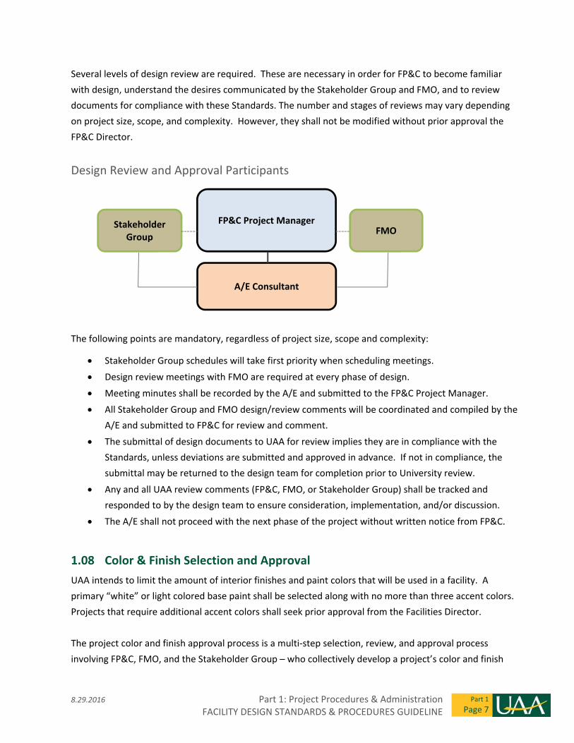
Design Review and Approval Participants
The following points are mandatory, regardless of project size, scope and complexity:
Stakeholder Group schedules will take first priority when scheduling meetings.
Design review meetings with FMO are required at every phase of design.
Meeting minutes shall be recorded by the A/E and submitted to the FP&C Project Manager.
All Stakeholder Group and FMO design/review comments will be coordinated and compiled by the
A/E and submitted to FP&C for review and comment.
The submittal of design documents to UAA for review implies they are in compliance with the
Standards, unless deviations are submitted and approved in advance. If not in compliance, the
submittal may be returned to the design team for completion prior to University review.
Any and all UAA review comments (FP&C, FMO, or Stakeholder Group) shall be tracked and
responded to by the design team to ensure consideration, implementation, and/or discussion.
The A/E shall not proceed with the next phase of the project without written notice from FP&C.
1.08 Color & Finish Selection and Approval
UAA intends to limit the amount of interior finishes and paint colors that will be used in a facility. A
primary “white” or light colored base paint shall be selected along with no more than three accent colors.
Projects that require additional accent colors shall seek prior approval from the Facilities Director.
The project color and finish approval process is a multi‐step selection, review, and approval process
involving FP&C, FMO, and the Stakeholder Group – who collectively develop a project’s color and finish
Stakeholder Group
FP&C Project Manager FMO
A/E Consultant
Part 1: Project Procedures & Administration 8.29.2016 FACILITY DESIGN STANDARDS & PROCEDURES GUIDELINE
Part 1
Page 8
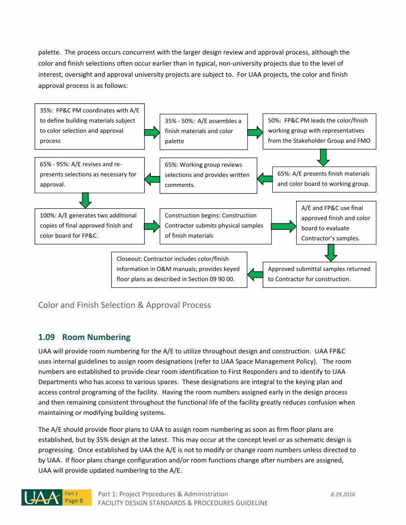
palette. The process occurs concurrent with the larger design review and approval process, although the
color and finish selections often occur earlier than in typical, non‐university projects due to the level of
interest, oversight and approval university projects are subject to. For UAA projects, the color and finish
approval process is as follows:
Color and Finish Selection & Approval Process
1.09 Room Numbering
UAA will provide room numbering for the A/E to utilize throughout design and construction. UAA FP&C
uses internal guidelines to assign room designations (refer to UAA Space Management Policy). The room
numbers are established to provide clear room identification to First Responders and to identify to UAA
Departments who has access to various spaces. These designations are integral to the keying plan and
access control programing of the facility. Having the room numbers assigned early in the design process
and then remaining consistent throughout the functional life of the facility greatly reduces confusion when
maintaining or modifying building systems.
The A/E should provide floor plans to UAA to assign room numbering as soon as firm floor plans are
established, but by 35% design at the latest. This may occur at the concept level or as schematic design is
progressing. Once established by UAA the A/E is not to modify or change room numbers unless directed to
by UAA. If floor plans change configuration and/or room functions change after numbers are assigned,
UAA will provide updated numbering to the A/E.
35%: FP&C PM coordinates with A/E
to define building materials subject
to color selection and approval
process
35% ‐ 50%: A/E assembles a
finish materials and color
palette
50%: FP&C PM leads the color/finish
working group with representatives
from the Stakeholder Group and FMO
65%: A/E presents finish materials
and color board to working group.
65%: Working group reviews
selections and provides written
comments.
65% ‐ 95%: A/E revises and re‐
presents selections as necessary for
approval.
100%: A/E generates two additional
copies of final approved finish and
color board for FP&C.
Construction begins: Construction
Contractor submits physical samples
of finish materials
A/E and FP&C use final
approved finish and color
board to evaluate
Contractor’s samples.
Approved submittal samples returned
to Contractor for construction.
Closeout: Contractor includes color/finish
information in O&M manuals; provides keyed
floor plans as described in Section 09 90 00.
8.29.2016 Part 1: Project Procedures & Administration FACILITY DESIGN STANDARDS & PROCEDURES GUIDELINE
Part 1
Page 9
1.10 Post Occupancy Evaluation
On major projects and as requested by the FP&C PM, the A/E should plan for a post occupancy evaluation
approximately eleven months after occupancy. The A/E team should perform a warranty inspection and
prepare a written report to provide UAA with a document that can be sent to the construction contractor
for correction of the work if required. Additionally, the A/E should attend and lead a Post Occupancy
“lessons learned” workshop with the building occupants (User Group), FMO and FP&C. A follow up report
and record of the workshop should be submitted by the A/E to FP&C.
Part 1: Project Procedures & Administration 8.29.2016 FACILITY DESIGN STANDARDS & PROCEDURES GUIDELINE
Part 1
Page 10
THIS PAGE INTENTIONALLY LEFT BLANK

THIS PAGE INTENTIONALLY LEFT BLANK
8.29.2016 Part 2: Campus Design Standards FACILITY DESIGN STANDARDS & PROCEDURES GUIDELINE
Part 2
Page 1
General Design Considerations
2.01 Codes and Standards
The Facility Design Standards and Procedures Guideline is intended to guide and standardize certain
aspects of building design on the UAA campus while working with all required building codes, regulatory
standards, and local requirements governing building design and construction within the Municipality of
Anchorage. In the event the A/E perceives a Standards requirement to conflict with code, the code
requirement shall govern and the A/E shall immediately notify the Facilities Planning & Construction
Project Manager and Director.
The following codes and standards were referenced in development of the current Document:
2009 International Building Code (IBC)
2009 International Mechanical Code (IMC)
2009 International Fire Code (IFC)
2009 International Fuel Gas Code (IFGC)
2009 International Energy Conservation Code (IECC)
2009 Uniform Plumbing Code (UPC)
2011 National Electrical Code (NEC)
American National Standards Institute (ANSI)
ANSI 117.1 Standard for Accessible and Usable Buildings and Facilities
American Society of Heating, Refrigerating and Air Conditioning Engineers (ASHRAE)
American Society for Testing and Materials (ASTM)
Underwriters’ Laboratories (UL)
Factory Mutual (FM)
California Technical Bulletin 133
National Fire Alarm Code, NFPA 72
Emergency and Standby Power Systems, NFPA 110
National Electrical Manufacturers’ Association (NEMA)
National Electrical Installation Standards (NEIS)
Illuminating Engineering Society of North America (IESNA)
Institute of Electrical and Electronic Engineers (IEEE)
Telecommunications Industry Association, Electronic Industries Association TIA/EIA
Municipal Code, Title 21 – Land Use Planning, Adopted 3 December 2013
Municipality of Anchorage Standard Specifications (M.A.S.S.) ‐ 2009 Revision 3.
Local Amendments adopted by the Municipality of Anchorage
Part 2: Campus Design Standards 8.29.2016 FACILITY DESIGN STANDARDS & PROCEDURES GUIDELINE
Part 2
Page 2
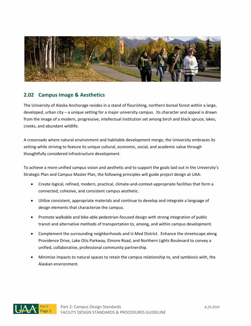
2.02 Campus Image & Aesthetics
The University of Alaska Anchorage resides in a stand of flourishing, northern boreal forest within a large,
developed, urban city – a unique setting for a major university campus. Its character and appeal is drawn
from the image of a modern, progressive, intellectual institution set among birch and black spruce, lakes,
creeks, and abundant wildlife.
A crossroads where natural environment and habitable development merge, the University embraces its
setting while striving to feature its unique cultural, economic, social, and academic value through
thoughtfully considered infrastructure development.
To achieve a more unified campus vision and aesthetic and to support the goals laid out in the University’s
Strategic Plan and Campus Master Plan, the following principles will guide project design at UAA:
Create logical, refined, modern, practical, climate‐and‐context‐appropriate facilities that form a
connected, cohesive, and consistent campus aesthetic.
Utilize consistent, appropriate materials and continue to develop and integrate a language of
design elements that characterize the campus.
Promote walkable and bike‐able pedestrian‐focused design with strong integration of public
transit and alternative methods of transportation to, among, and within campus development.
Complement the surrounding neighborhoods and U‐Med District. Enhance the streetscape along
Providence Drive, Lake Otis Parkway, Elmore Road, and Northern Lights Boulevard to convey a
unified, collaborative, professional community partnership.
Minimize impacts to natural spaces to retain the campus relationship to, and symbiosis with, the
Alaskan environment.
8.29.2016 Part 2: Campus Design Standards FACILITY DESIGN STANDARDS & PROCEDURES GUIDELINE
Part 2
Page 3
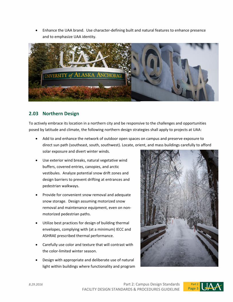
Enhance the UAA brand. Use character‐defining built and natural features to enhance presence
and to emphasize UAA identity.
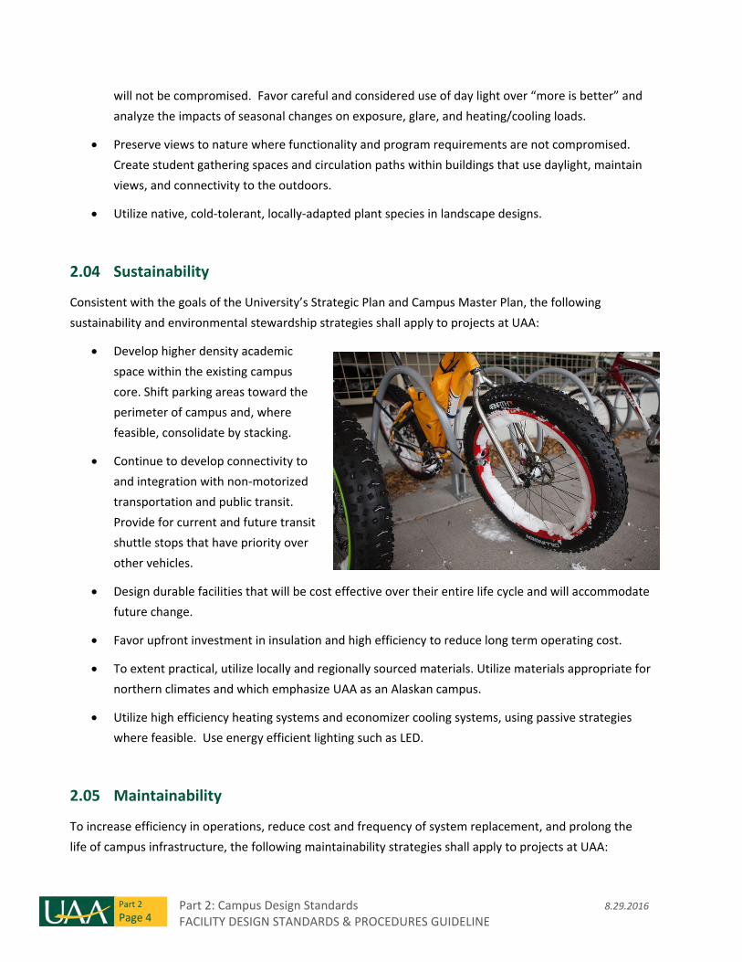
2.03 Northern Design
To actively embrace its location in a northern city and be responsive to the challenges and opportunities
posed by latitude and climate, the following northern design strategies shall apply to projects at UAA:
Add to and enhance the network of outdoor open spaces on campus and preserve exposure to
direct sun path (southeast, south, southwest). Locate, orient, and mass buildings carefully to afford
solar exposure and divert winter winds.
Use exterior wind breaks, natural vegetative wind
buffers, covered entries, canopies, and arctic
vestibules. Analyze potential snow drift zones and
design barriers to prevent drifting at entrances and
pedestrian walkways.
Provide for convenient snow removal and adequate
snow storage. Design assuming motorized snow
removal and maintenance equipment, even on non‐
motorized pedestrian paths.
Utilize best practices for design of building thermal
envelopes, complying with (at a minimum) IECC and
ASHRAE prescribed thermal performance.
Carefully use color and texture that will contrast with
the color‐limited winter season.
Design with appropriate and deliberate use of natural
light within buildings where functionality and program
Part 2: Campus Design Standards 8.29.2016 FACILITY DESIGN STANDARDS & PROCEDURES GUIDELINE
Part 2
Page 4
will not be compromised. Favor careful and considered use of day light over “more is better” and
analyze the impacts of seasonal changes on exposure, glare, and heating/cooling loads.
Preserve views to nature where functionality and program requirements are not compromised.
Create student gathering spaces and circulation paths within buildings that use daylight, maintain
views, and connectivity to the outdoors.
Utilize native, cold‐tolerant, locally‐adapted plant species in landscape designs.
2.04 Sustainability
Consistent with the goals of the University’s Strategic Plan and Campus Master Plan, the following
sustainability and environmental stewardship strategies shall apply to projects at UAA:
Develop higher density academic
space within the existing campus
core. Shift parking areas toward the
perimeter of campus and, where
feasible, consolidate by stacking.
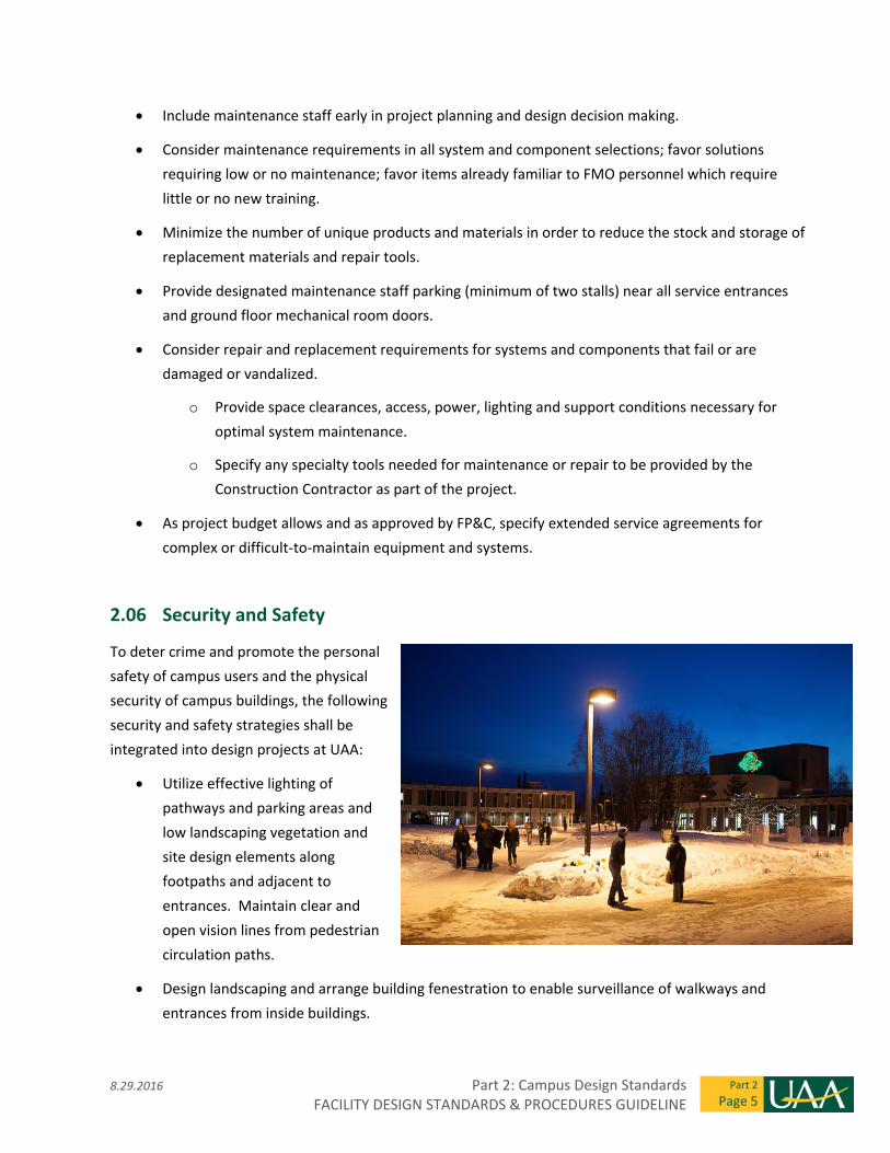
Continue to develop connectivity to
and integration with non‐motorized
transportation and public transit.
Provide for current and future transit
shuttle stops that have priority over
other vehicles.
Design durable facilities that will be cost effective over their entire life cycle and will accommodate
future change.
Favor upfront investment in insulation and high efficiency to reduce long term operating cost.
To extent practical, utilize locally and regionally sourced materials. Utilize materials appropriate for
northern climates and which emphasize UAA as an Alaskan campus.
Utilize high efficiency heating systems and economizer cooling systems, using passive strategies
where feasible. Use energy efficient lighting such as LED.
2.05 Maintainability
To increase efficiency in operations, reduce cost and frequency of system replacement, and prolong the
life of campus infrastructure, the following maintainability strategies shall apply to projects at UAA:
8.29.2016 Part 2: Campus Design Standards FACILITY DESIGN STANDARDS & PROCEDURES GUIDELINE
Part 2
Page 5
Include maintenance staff early in project planning and design decision making.
Consider maintenance requirements in all system and component selections; favor solutions
requiring low or no maintenance; favor items already familiar to FMO personnel which require
little or no new training.
Minimize the number of unique products and materials in order to reduce the stock and storage of
replacement materials and repair tools.
Provide designated maintenance staff parking (minimum of two stalls) near all service entrances
and ground floor mechanical room doors.
Consider repair and replacement requirements for systems and components that fail or are
damaged or vandalized.
o Provide space clearances, access, power, lighting and support conditions necessary for
optimal system maintenance.
o Specify any specialty tools needed for maintenance or repair to be provided by the
Construction Contractor as part of the project.
As project budget allows and as approved by FP&C, specify extended service agreements for
complex or difficult‐to‐maintain equipment and systems.
2.06 Security and Safety
To deter crime and promote the personal
safety of campus users and the physical
security of campus buildings, the following
security and safety strategies shall be
integrated into design projects at UAA:
Utilize effective lighting of
pathways and parking areas and
low landscaping vegetation and
site design elements along
footpaths and adjacent to
entrances. Maintain clear and
open vision lines from pedestrian
circulation paths.
Design landscaping and arrange building fenestration to enable surveillance of walkways and
entrances from inside buildings.
Part 2: Campus Design Standards 8.29.2016 FACILITY DESIGN STANDARDS & PROCEDURES GUIDELINE
Part 2
Page 6
Provide predictable locations of and clear lines of site to emergency phones and building
entrances.
Enhance building security with centrally managed and alarmed electronic access control, glass
break detectors where necessary, and local audible alarms where risk is high.
Coordinate security strategy, camera locations, and emergency phones with UPD. Provide rough‐in
for future cameras as budget allows (conduit placement during construction is easier than post‐
occupancy).
2.07 Flexibility & Future Planning
To accommodate change and growth in UAA’s program requirements in the future, the following
strategies shall be considered in designing projects at UAA:
Show how and where future expansion is accommodated on site.
Utilize “the least permanent but effective” means of dividing spaces within buildings to allow
future reconfiguration.
Consider how and where the campus circulation spine will connect and integrate into buildings.
Size equipment and systems to accommodate 125%‐150% of the present design load, as practical
within area and budget constraints.
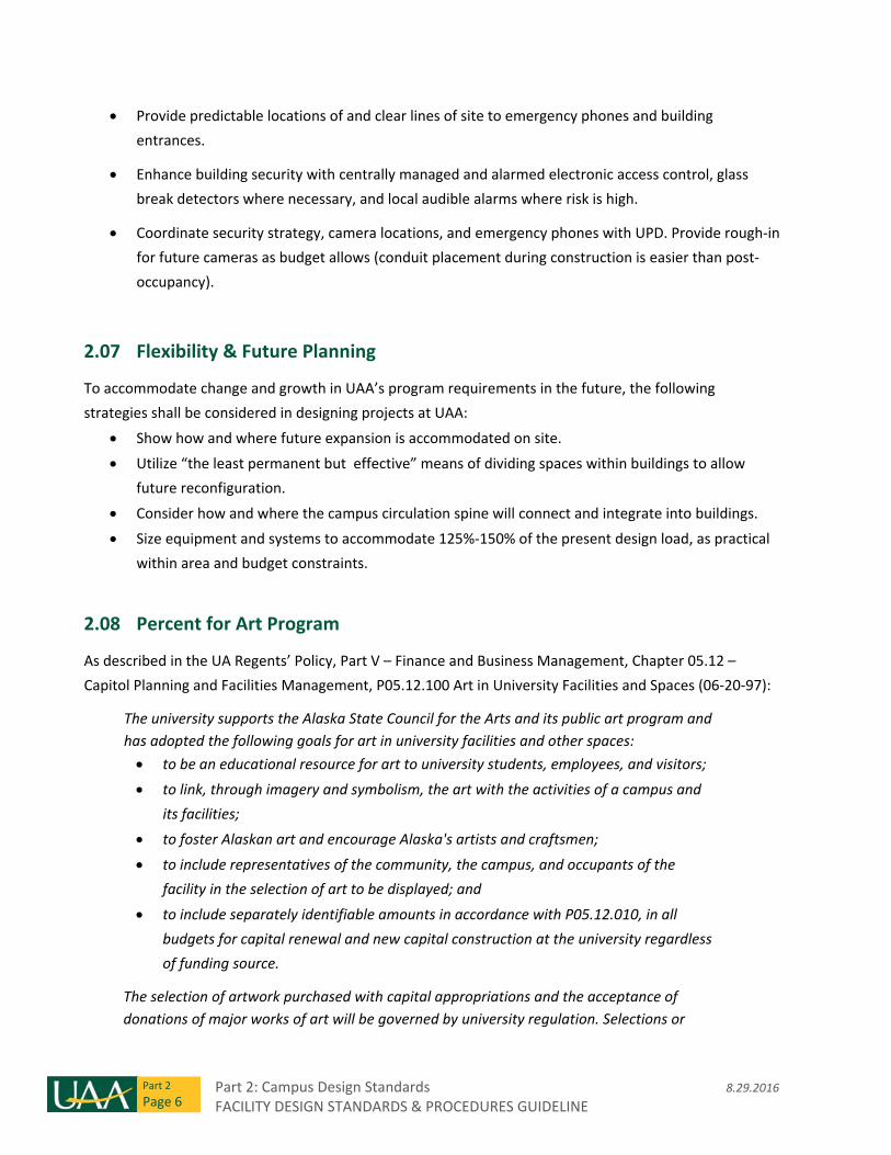
2.08 Percent for Art Program
As described in the UA Regents’ Policy, Part V – Finance and Business Management, Chapter 05.12 –
Capitol Planning and Facilities Management, P05.12.100 Art in University Facilities and Spaces (06‐20‐97):
The university supports the Alaska State Council for the Arts and its public art program and
has adopted the following goals for art in university facilities and other spaces:
to be an educational resource for art to university students, employees, and visitors;
to link, through imagery and symbolism, the art with the activities of a campus and
its facilities;
to foster Alaskan art and encourage Alaska's artists and craftsmen;
to include representatives of the community, the campus, and occupants of the
facility in the selection of art to be displayed; and
to include separately identifiable amounts in accordance with P05.12.010, in all
budgets for capital renewal and new capital construction at the university regardless
of funding source.
The selection of artwork purchased with capital appropriations and the acceptance of
donations of major works of art will be governed by university regulation. Selections or
8.29.2016 Part 2: Campus Design Standards FACILITY DESIGN STANDARDS & PROCEDURES GUIDELINE
Part 2
Page 7
acceptances of works of art valued at more than $100,000 will be referred to the board for
comment before final approval by the appropriate chancellor and the president.
As a part of the planning, design, and execution of new and renovated facilities that have a Public Art
component the design team will:
Accommodate and identify potential sites for art installations within the project boundaries. Both
interior and exterior sites shall be considered.
Consider future expansion and additions when selecting art sites. Once Public Art in installed in a
facility it cannot be moved or decommissioned without re‐administering the art selection process.
Consider how the architectural design will support the art, including protection of the art from
vandalism and maintenance equipment required to service the building.
Consider structural supports and reinforcement to physically secure the art work.
Consider how electrical power and accent lighting are provided at anticipated art installations.
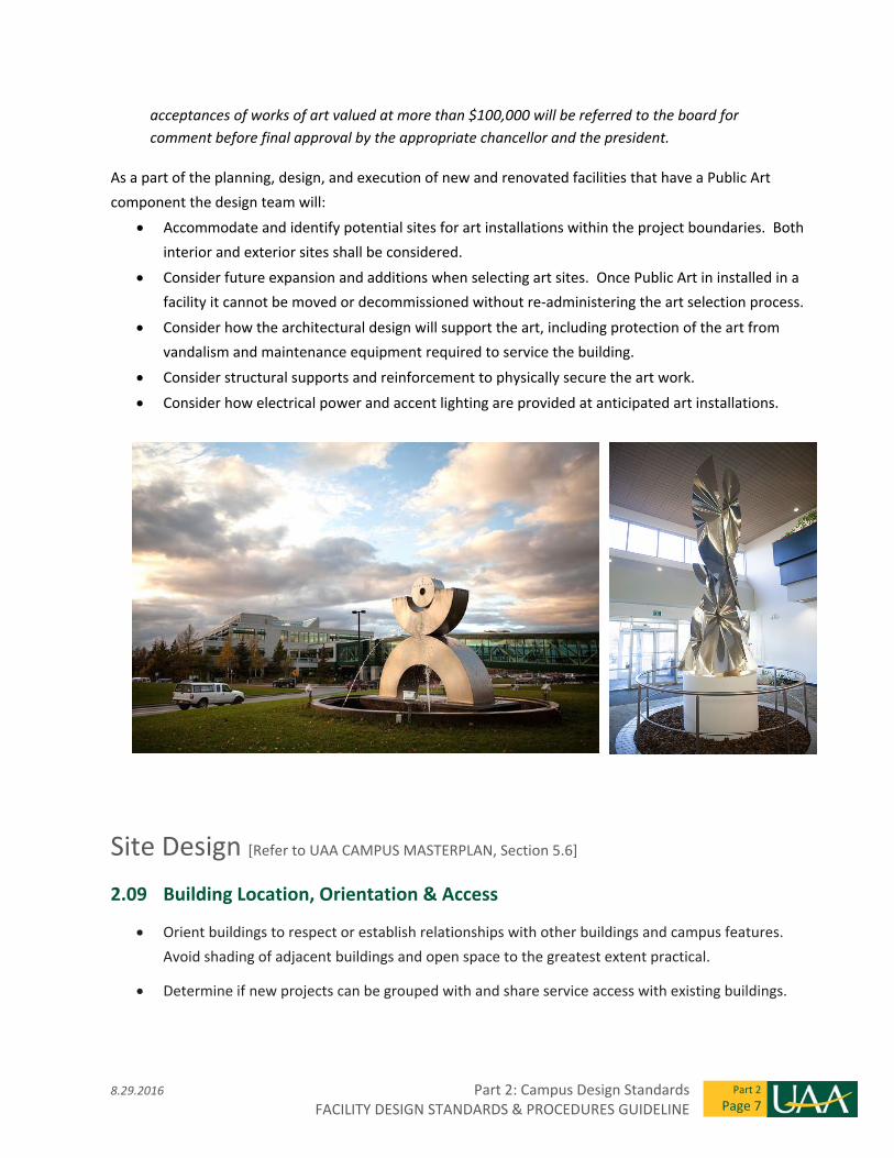
Site Design [Refer to UAA CAMPUS MASTERPLAN, Section 5.6]
2.09 Building Location, Orientation & Access
Orient buildings to respect or establish relationships with other buildings and campus features.
Avoid shading of adjacent buildings and open space to the greatest extent practical.
Determine if new projects can be grouped with and share service access with existing buildings.
Part 2: Campus Design Standards 8.29.2016 FACILITY DESIGN STANDARDS & PROCEDURES GUIDELINE
Part 2
Page 8
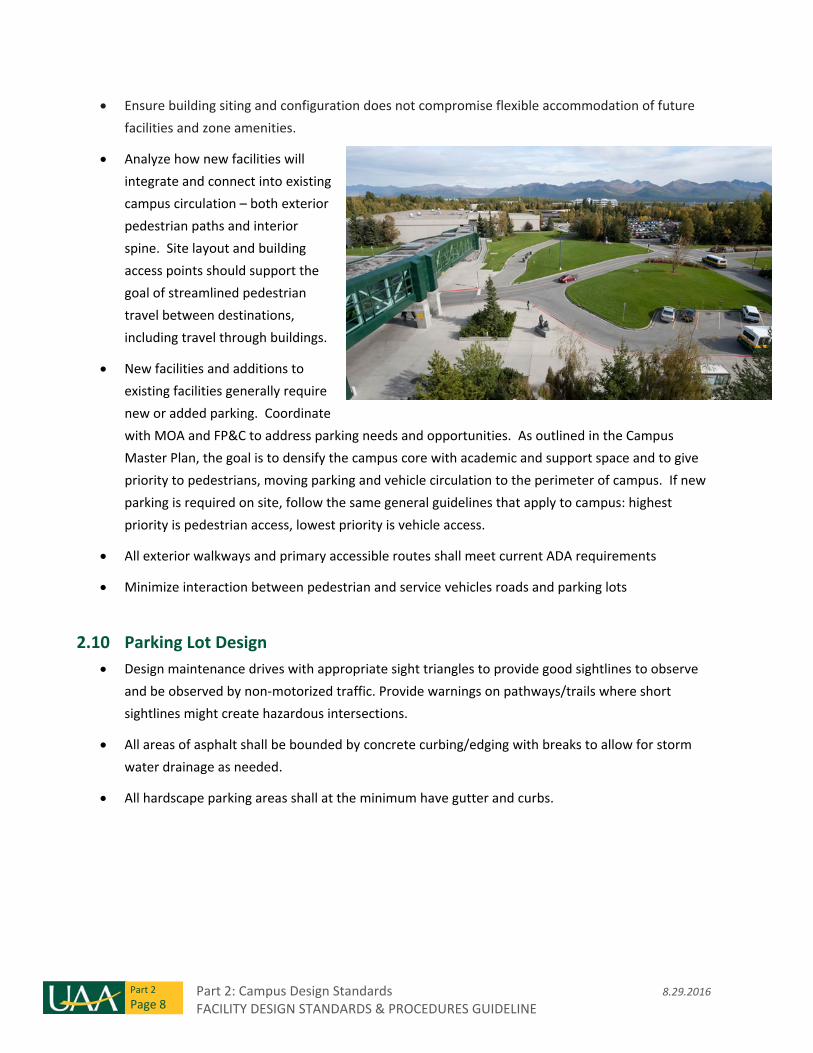
Ensure building siting and configuration does not compromise flexible accommodation of future
facilities and zone amenities.
Analyze how new facilities will
integrate and connect into existing
campus circulation – both exterior
pedestrian paths and interior
spine. Site layout and building
access points should support the
goal of streamlined pedestrian
travel between destinations,
including travel through buildings.
New facilities and additions to
existing facilities generally require
new or added parking. Coordinate
with MOA and FP&C to address parking needs and opportunities. As outlined in the Campus
Master Plan, the goal is to densify the campus core with academic and support space and to give
priority to pedestrians, moving parking and vehicle circulation to the perimeter of campus. If new
parking is required on site, follow the same general guidelines that apply to campus: highest
priority is pedestrian access, lowest priority is vehicle access.
All exterior walkways and primary accessible routes shall meet current ADA requirements
Minimize interaction between pedestrian and service vehicles roads and parking lots
2.10 Parking Lot Design
Design maintenance drives with appropriate sight triangles to provide good sightlines to observe
and be observed by non‐motorized traffic. Provide warnings on pathways/trails where short
sightlines might create hazardous intersections.
All areas of asphalt shall be bounded by concrete curbing/edging with breaks to allow for storm
water drainage as needed.
All hardscape parking areas shall at the minimum have gutter and curbs.
8.29.2016 Part 2: Campus Design Standards FACILITY DESIGN STANDARDS & PROCEDURES GUIDELINE
Part 2
Page 9
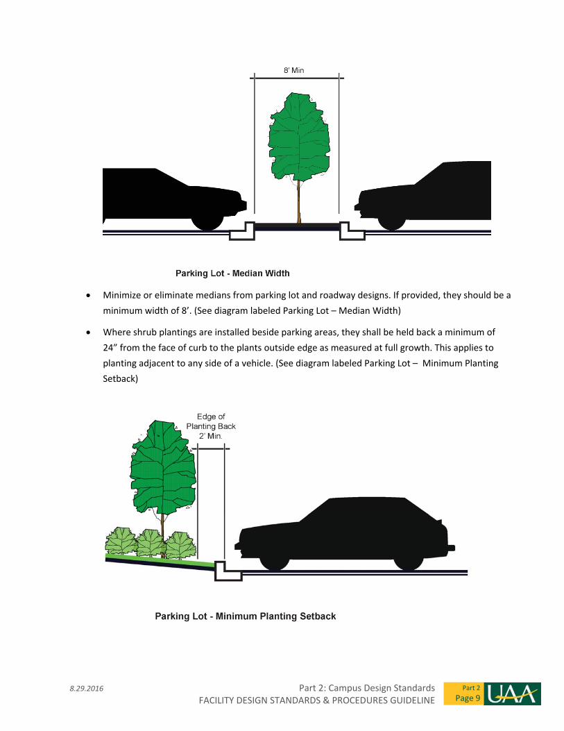
Minimize or eliminate medians from parking lot and roadway designs. If provided, they should be a
minimum width of 8’. (See diagram labeled Parking Lot – Median Width)
Where shrub plantings are installed beside parking areas, they shall be held back a minimum of
24” from the face of curb to the plants outside edge as measured at full growth. This applies to
planting adjacent to any side of a vehicle. (See diagram labeled Parking Lot – Minimum Planting
Setback)
Part 2: Campus Design Standards 8.29.2016 FACILITY DESIGN STANDARDS & PROCEDURES GUIDELINE
Part 2
Page 10
Parking lot interior landscape beds shall use shredded bark mulch, mineral mulch, or a
groundcover. No maintained grass shall be used in these landscape beds.
As possible, parking rows should be defined to allow vehicle alignment when there is snow on the
ground. This may take the form of landscape end caps, light pole bases or other permanent visible
features. Temporary markers should not be used.
2.11 Pedestrian and Non‐Motorized Vehicle Access
All exterior horizontal surfaces shall be slip‐resistant
Exterior pathways shall all be concrete and shall have broom finish, perpendicular to direction of
traffic.
Design all sidewalks and pathways to accommodate service vehicles up to 12,000 lbs.
No tile inlays on exterior horizontal surfaces. Stamped concrete or asphalt is not recommended for
exterior horizontal surfaces
All main entries shall have bike racks.
Provide a minimum of 12 bike rack spaces per building. As possible, integrate covered bicycle
parking into building entry canopy designs.
Covered bicycle parking shall have roofing that sheds snow/water away from pedestrian areas.
2.12 Site Clearing and Protection
Existing structures, landscape, appurtenances and other features indicated to remain shall be
protected during construction.
Topsoil stripping, stockpiling and re‐use are only acceptable if soils to be re‐used are placed below
10” of new planting soil. Re‐used soils should be expected to have weed species present, and not
used in a way that will allow germination.
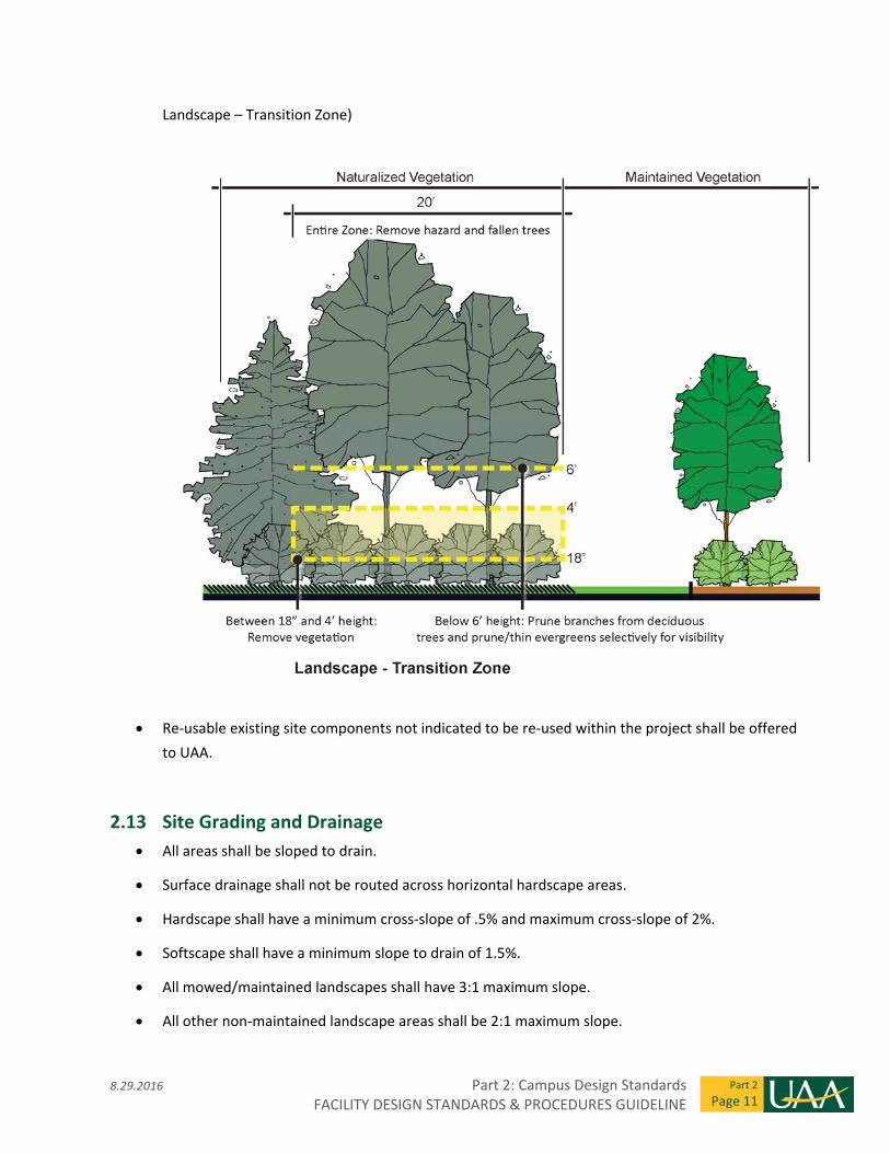
Where existing vegetation is to remain, a 20’ transition zone shall be provided in order to increase
safety and develop a higher aesthetic. Hazardous and fallen trees shall be removed, invasive
species shall be removed, vegetation between 18” and 48” in height shall be removed, branches
below 6’ shall be pruned from deciduous trees, and evergreen trees shall be removed/pruned
selectively for visibility. Work shall be done with guidance from UAA Operations. Create 20’
transition zone between naturalized plantings and maintained plantings. (See diagram labeled
8.29.2016 Part 2: Campus Design Standards FACILITY DESIGN STANDARDS & PROCEDURES GUIDELINE
Part 2
Page 11
Landscape – Transition Zone)
Re‐usable existing site components not indicated to be re‐used within the project shall be offered
to UAA.
2.13 Site Grading and Drainage
All areas shall be sloped to drain.
Surface drainage shall not be routed across horizontal hardscape areas.
Hardscape shall have a minimum cross‐slope of .5% and maximum cross‐slope of 2%.
Softscape shall have a minimum slope to drain of 1.5%.
All mowed/maintained landscapes shall have 3:1 maximum slope.
All other non‐maintained landscape areas shall be 2:1 maximum slope.
Part 2: Campus Design Standards 8.29.2016 FACILITY DESIGN STANDARDS & PROCEDURES GUIDELINE
Part 2
Page 12
In order to facilitate maintenance, there shall be a 10’ width area around the base of each building
that is 2% slope maximum, grading away from building.
Areas of softscape that are designed to act as channels for water shall not be seeded. They shall be
sodded, or rock mulch of a sufficient size to not be moved by expected water flow. These materials
shall be installed to extents extending above the typical expected height of water.
Exceptions to grading and drainage design guidelines require approval from UAA.
2.14 Exterior Site Furniture and Amenities
All products and fabrications shall be commercial grade.
Site furniture shall be located to avoid conflicts with utilities and to minimize conflict with
maintenance operations, with specific focus on snow removal.
All site elements less than 30” height that could be subject to skateboarding shall be designed to
discourage skateboarding. This does not apply to curbing. Preference should be given to designs
that discourage skateboarding, rather than using anti‐skateboarding attachments.
Campus‐wide standard elements shall have standard finishes and colors per Part 3 of this
document.
Non‐standard site furnishings should meet the intent, guidelines, sustainability, and maintenance
requirements as outlined in the 2013 Campus Master Plan.
Preferred exterior seat wall design is a concrete wall with footing with wood cap.
2.15 Exterior Materials and Finishes ‐ General
Exterior finish products near building entries and service areas are subject to frequent contact and
damage. Avoid use of easily damaged finishes at these locations.
Commercial standards for metal shall be used.
All exterior fasteners shall be corrosion resistant and matched to metal types to eliminate galvanic
reaction or similar. Preference is for stainless steel or hot‐dipped galvanized.
Hardware for fabrications in easily accessible settings shall use tamper‐proof fasteners.
Any metal within a horizontal surface that can be walked on shall have an anti‐slip surface.
Stainless steel with a brushed finish is the preferred exterior material where no finish is desired.
8.29.2016 Part 2: Campus Design Standards FACILITY DESIGN STANDARDS & PROCEDURES GUIDELINE
Part 2
Page 13
Exterior grade powder coat with a zinc rich epoxy primer (or equivalent) is the preferred finish
where an aesthetic coating is desired.
Hot dip galvanized steel is the preferred exterior material where longevity is desired for utilitarian
purposed, or where the finish is a desired aesthetic. Field welding should be avoided, but if
necessary welds shall be field‐coated as recommended by manufacturer to achieve appropriate
corrosion resistance.
2.16 Landscaping
Planting designs on campus shall:
Reinforce site and architectural geometries. Planting plans should be intentional and:
o Reinforce placement of architectural and site elements (i.e. columns and light pole placement)
through symmetry, repetition, alignment, etc.
o Maintain and frame important views as identified in the Campus Master Plan.
Be coordinated with building utilities.
o Coordinate placement of plantings with all utility structures.
o Eliminate improper planting around building intakes (or other systems) where leaves or other
material could get into systems.
Maintain the safety of the site user.
o Allow proper visibility around, within, and between pedestrian and vehicular areas,
o Allow a high level of visibility where pedestrian pathways intersect with vehicular routes,
including maintenance access routes.
Enhance the user experience on site.
o Protect current and future desired solar access of nearby buildings and exterior gathering
areas.
o Screen winds.
Minimize maintenance and reduce long‐term costs.
o Keep planting designs simple and natural in character, with more formal plantings used
sparingly in key locations.
o Provide definitive lines and access for mowing.
o Avoid the use of plants that drop fruit on or immediately next to paved surfaces
Part 2: Campus Design Standards 8.29.2016 FACILITY DESIGN STANDARDS & PROCEDURES GUIDELINE
Part 2
Page 14
o Use species that reduce the need for pesticides, herbicides, and other chemical applications.
o Provide a 20’ wide transition area between naturalized plantings (unmaintained, existing
forest vegetation) and maintained plantings. Transition area is a strip of naturalized plantings
in which some clearing and grubbing has occurred (i.e. dead and fallen plantings, invasive
species, and unsightly plants are removed and sight lines are improved). Reference 2.12 Site
Clearing and Protection for more detailed description.
o Locate with consideration of other design elements:
Match plant types and planting design to the intent of the area. (i.e. low ornamental
plants shall not be used within no‐mow grass areas)
Place shrubs a minimum ½ of expected mature width from edge of hardscape areas,
maintained turf areas or similar areas where branches will get in the way of activities.
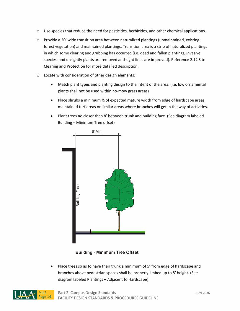
Plant trees no closer than 8’ between trunk and building face. (See diagram labeled
Building – Minimum Tree offset)
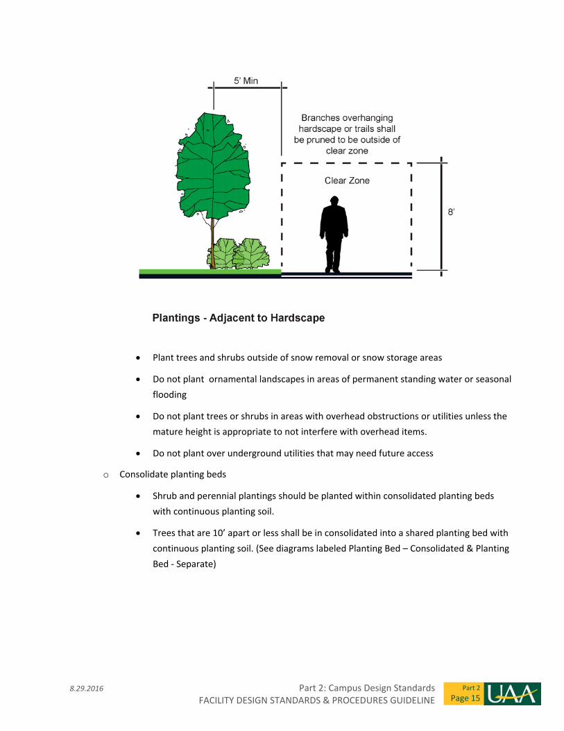
Place trees so as to have their trunk a minimum of 5’ from edge of hardscape and
branches above pedestrian spaces shall be properly limbed up to 8’ height. (See
diagram labeled Plantings – Adjacent to Hardscape)
8.29.2016 Part 2: Campus Design Standards FACILITY DESIGN STANDARDS & PROCEDURES GUIDELINE
Part 2
Page 15
Plant trees and shrubs outside of snow removal or snow storage areas
Do not plant ornamental landscapes in areas of permanent standing water or seasonal
flooding
Do not plant trees or shrubs in areas with overhead obstructions or utilities unless the
mature height is appropriate to not interfere with overhead items.
Do not plant over underground utilities that may need future access
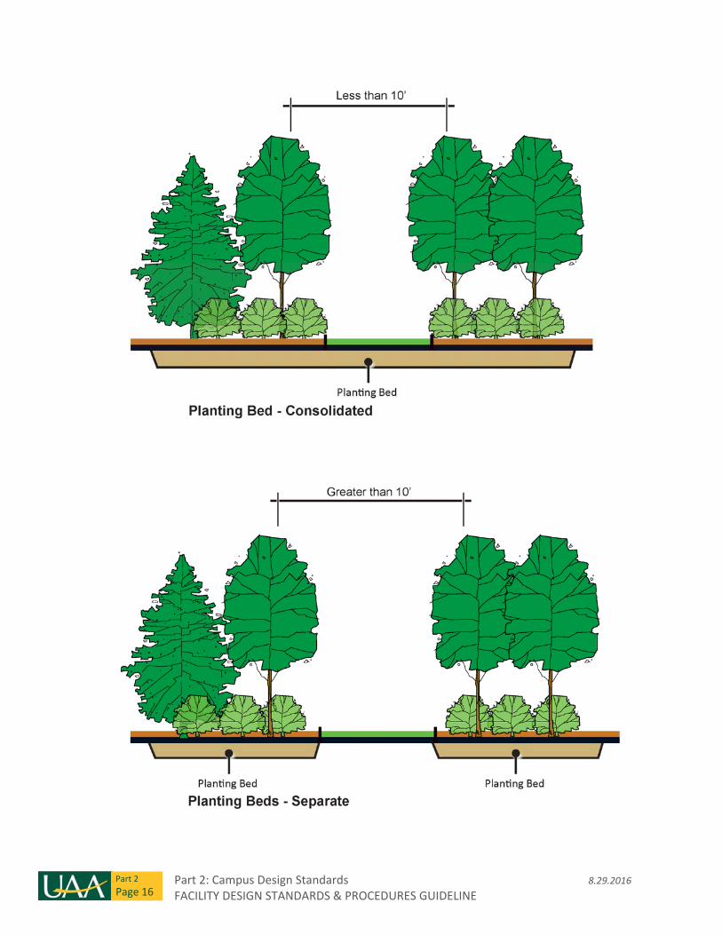
o Consolidate planting beds
Shrub and perennial plantings should be planted within consolidated planting beds
with continuous planting soil.
Trees that are 10’ apart or less shall be in consolidated into a shared planting bed with
continuous planting soil. (See diagrams labeled Planting Bed – Consolidated & Planting
Bed ‐ Separate)
Part 2: Campus Design Standards 8.29.2016 FACILITY DESIGN STANDARDS & PROCEDURES GUIDELINE
Part 2
Page 16
8.29.2016 Part 2: Campus Design Standards FACILITY DESIGN STANDARDS & PROCEDURES GUIDELINE
Part 2
Page 17
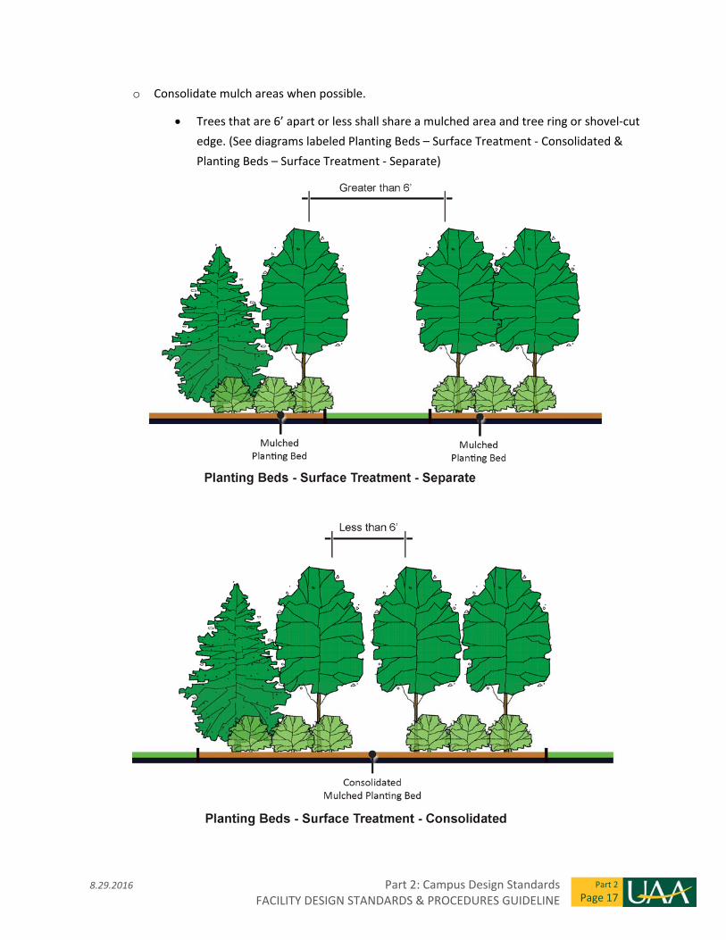
o Consolidate mulch areas when possible.
Trees that are 6’ apart or less shall share a mulched area and tree ring or shovel‐cut
edge. (See diagrams labeled Planting Beds – Surface Treatment ‐ Consolidated &
Planting Beds – Surface Treatment ‐ Separate)
Part 2: Campus Design Standards 8.29.2016 FACILITY DESIGN STANDARDS & PROCEDURES GUIDELINE
Part 2
Page 18
If trees are 8’ apart or less, continuous moose protection will be used around the
grouping of trees.
Do not plant trees closer than 8’ from building face.
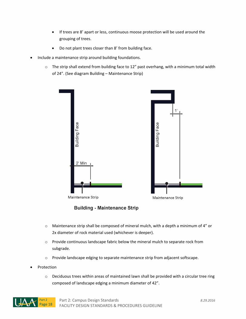
Include a maintenance strip around building foundations.
o The strip shall extend from building face to 12” past overhang, with a minimum total width
of 24”. (See diagram Building – Maintenance Strip)
o Maintenance strip shall be composed of mineral mulch, with a depth a minimum of 4” or
2x diameter of rock material used (whichever is deeper).
o Provide continuous landscape fabric below the mineral mulch to separate rock from
subgrade.
o Provide landscape edging to separate maintenance strip from adjacent softscape.
Protection
o Deciduous trees within areas of maintained lawn shall be provided with a circular tree ring
composed of landscape edging a minimum diameter of 42”.
8.29.2016 Part 2: Campus Design Standards FACILITY DESIGN STANDARDS & PROCEDURES GUIDELINE
Part 2
Page 19
o Evergreen trees within areas of maintained lawn shall be provided with individual mulch
beds around the trunk and a 42” diameter shovel‐cut edge between mulch and lawn.
o Meet local code, Title 21 requirements, and use MASS as a guiding document except
where noted.
Considerations for plant choice:
o Use local native plant species or locally adapted species that are shown to be hardy to
Anchorage and the UAA campus and which require little long‐term maintenance.
o Can withstand typical local dry periods.
o Are sized to reduce damage from moose, or are not a moose preference. Species of plants
that are known to attract moose should be avoided, or used in a manner that minimizes
exposure to moose browse.
o Minimize attractiveness to bears.
o Provide winter or seasonal interest.
o Blend well with surrounding landscapes.
o Have a variety of sizes, calipers, and shapes in order to minimize the visual impact of plant
mortality and replacement.
o Maintain good visibility to avoid conflicts between pedestrians, wildlife, and vehicles.
o Deciduous trees shall have a minimum caliper size of 2” (or as dictated by code if greater).
o Evergreen trees shall have a minimum height of 8’ (or as dictated by code if greater).
Keep planting designs simple and natural in character, with more formal plantings used sparingly
in key locations. Use species that reduce the need for pesticides, herbicides, and other chemical
applications.
Consider placement of snow markers for winter maintenance in the layout of exterior hardscape
spaces.
2.17 Irrigation
All irrigation components shall be commercial grade or better.
Buildings shall have hose bibs at entries and a desired maximum of 75’ apart along the building
face.
A manual irrigation system with quick couplers approximately 100’ O.C. to allow irrigation of all planting areas within a site is desired. Layout shall allow complete coverage without crossing of vehicular pavement or pedestrian walkways.
Part 2: Campus Design Standards 8.29.2016 FACILITY DESIGN STANDARDS & PROCEDURES GUIDELINE
Part 2
Page 20
Coordinate exterior electrical power receptacle locations as described in section 2.47 with irrigation system building connection points.
Provide slow release watering bags for trees.
Allow for future system expansion in the system design with location of sleeves under hardscape
where expansion is likely.
If an automated system is provided:
o Irrigation systems shall be fully automated and provide a volume of water suitable to
promote vigorous plant growth and be designed to operate at night between 10:00pm and
7:00am (allowing 56 hours of weekly operation). The designer/contractor is given full
flexibility for the layout, design and use of irrigation equipment to meet stated system
design criteria pending design approval.
o Velocity of water through irrigation lines shall not exceed five (5) feet per second.
o Design shall allow for easy operation and maintenance, and have the ability to be fully
“blown out” and winterized at the end of the irrigation season, prior to first frost.
o The system shall be fully automatic and shall incorporate a rain gauge function to override
normal programming.
Non‐standard irrigation designs and products should meet the intent, guidelines, sustainability,
and maintenance requirements as outlined in the 2013 Campus Master Plan
2.18 Snow Removal & Storage
Snow must be accommodated on site, and storage areas must meet MOA requirements.
Design and locate site elements so as to minimize conflict with maintenance operations, with
specific focus on snow removal.
Snow storage areas on site must allow access for large vehicles in the event that snow
accumulation warrants removal and trucking off site.
Snow storage areas must coordinate with landscape design and must prevent damage to plants,
grasses and site furnishings.
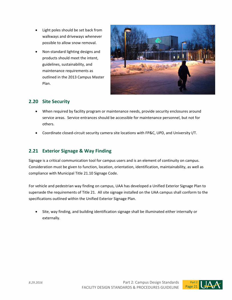
2.19 Site Lighting
Site lighting layout must consider both pedestrian safety and ease of maintenance, particularly
with regard to snow removal.
8.29.2016 Part 2: Campus Design Standards FACILITY DESIGN STANDARDS & PROCEDURES GUIDELINE
Part 2
Page 21
Light poles should be set back from
walkways and driveways whenever
possible to allow snow removal.
Non‐standard lighting designs and
products should meet the intent,
guidelines, sustainability, and
maintenance requirements as
outlined in the 2013 Campus Master
Plan.
2.20 Site Security
When required by facility program or maintenance needs, provide security enclosures around
service areas. Service entrances should be accessible for maintenance personnel, but not for
others.
Coordinate closed‐circuit security camera site locations with FP&C, UPD, and University I/T.
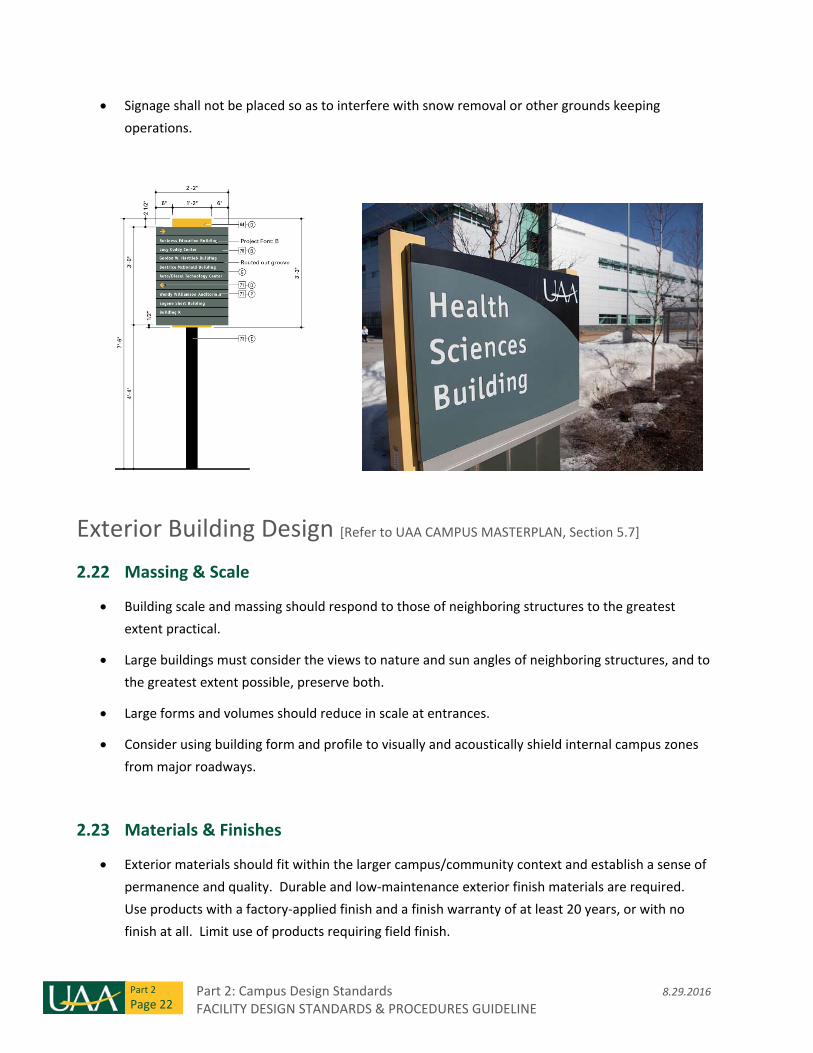
2.21 Exterior Signage & Way Finding
Signage is a critical communication tool for campus users and is an element of continuity on campus.
Consideration must be given to function, location, orientation, identification, maintainability, as well as
compliance with Municipal Title 21.10 Signage Code.
For vehicle and pedestrian way finding on campus, UAA has developed a Unified Exterior Signage Plan to
supersede the requirements of Title 21. All site signage installed on the UAA campus shall conform to the
specifications outlined within the Unified Exterior Signage Plan.
Site, way finding, and building identification signage shall be illuminated either internally or
externally.
Part 2: Campus Design Standards 8.29.2016 FACILITY DESIGN STANDARDS & PROCEDURES GUIDELINE
Part 2
Page 22
Signage shall not be placed so as to interfere with snow removal or other grounds keeping
operations.
Exterior Building Design [Refer to UAA CAMPUS MASTERPLAN, Section 5.7]
2.22 Massing & Scale
Building scale and massing should respond to those of neighboring structures to the greatest
extent practical.
Large buildings must consider the views to nature and sun angles of neighboring structures, and to
the greatest extent possible, preserve both.
Large forms and volumes should reduce in scale at entrances.
Consider using building form and profile to visually and acoustically shield internal campus zones
from major roadways.
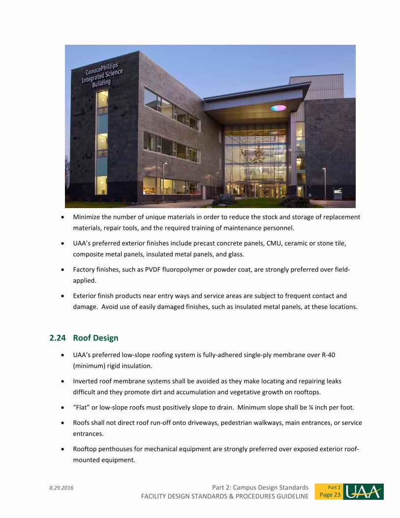
2.23 Materials & Finishes
Exterior materials should fit within the larger campus/community context and establish a sense of
permanence and quality. Durable and low‐maintenance exterior finish materials are required.
Use products with a factory‐applied finish and a finish warranty of at least 20 years, or with no
finish at all. Limit use of products requiring field finish.
8.29.2016 Part 2: Campus Design Standards FACILITY DESIGN STANDARDS & PROCEDURES GUIDELINE
Part 2
Page 23
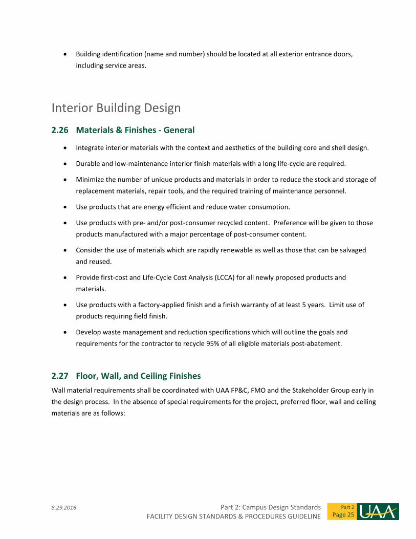
Minimize the number of unique materials in order to reduce the stock and storage of replacement
materials, repair tools, and the required training of maintenance personnel.
UAA’s preferred exterior finishes include precast concrete panels, CMU, ceramic or stone tile,
composite metal panels, insulated metal panels, and glass.
Factory finishes, such as PVDF fluoropolymer or powder coat, are strongly preferred over field‐
applied.
Exterior finish products near entry ways and service areas are subject to frequent contact and
damage. Avoid use of easily damaged finishes, such as insulated metal panels, at these locations.
2.24 Roof Design
UAA’s preferred low‐slope roofing system is fully‐adhered single‐ply membrane over R‐40
(minimum) rigid insulation.
Inverted roof membrane systems shall be avoided as they make locating and repairing leaks
difficult and they promote dirt and accumulation and vegetative growth on rooftops.
“Flat” or low‐slope roofs must positively slope to drain. Minimum slope shall be ¼ inch per foot.
Roofs shall not direct roof run‐off onto driveways, pedestrian walkways, main entrances, or service
entrances.
Rooftop penthouses for mechanical equipment are strongly preferred over exposed exterior roof‐
mounted equipment.
Part 2: Campus Design Standards 8.29.2016 FACILITY DESIGN STANDARDS & PROCEDURES GUIDELINE
Part 2
Page 24
Secured stair access and/or elevator access to rooftops is desired for maintenance; avoid using
ladders as the only means of roof access where roof‐mounted equipment is present.
Rooftop fall protection is required. On low‐slope roofs, 42” high roof parapet walls are desirable
for fall protection and safe rooftop maintenance. Alternate fall protection is permitted with FP&C
and FMO approval.
Rooftop equipment requiring maintenance in a kneeling or prone position requires a raised service
platform to prevent maintenance personnel from having to lie on wet roofs.
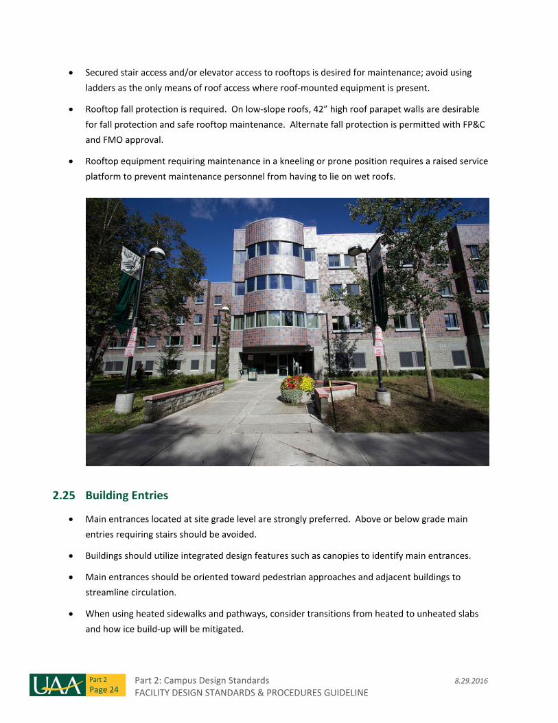
2.25 Building Entries
Main entrances located at site grade level are strongly preferred. Above or below grade main
entries requiring stairs should be avoided.
Buildings should utilize integrated design features such as canopies to identify main entrances.
Main entrances should be oriented toward pedestrian approaches and adjacent buildings to
streamline circulation. When using heated sidewalks and pathways, consider transitions from heated to unheated slabs
and how ice build‐up will be mitigated.
8.29.2016 Part 2: Campus Design Standards FACILITY DESIGN STANDARDS & PROCEDURES GUIDELINE
Part 2
Page 25
Building identification (name and number) should be located at all exterior entrance doors,
including service areas.
Interior Building Design
2.26 Materials & Finishes ‐ General
Integrate interior materials with the context and aesthetics of the building core and shell design.
Durable and low‐maintenance interior finish materials with a long life‐cycle are required.
Minimize the number of unique products and materials in order to reduce the stock and storage of
replacement materials, repair tools, and the required training of maintenance personnel.
Use products that are energy efficient and reduce water consumption.
Use products with pre‐ and/or post‐consumer recycled content. Preference will be given to those
products manufactured with a major percentage of post‐consumer content.
Consider the use of materials which are rapidly renewable as well as those that can be salvaged
and reused.
Provide first‐cost and Life‐Cycle Cost Analysis (LCCA) for all newly proposed products and
materials.
Use products with a factory‐applied finish and a finish warranty of at least 5 years. Limit use of
products requiring field finish.
Develop waste management and reduction specifications which will outline the goals and
requirements for the contractor to recycle 95% of all eligible materials post‐abatement.
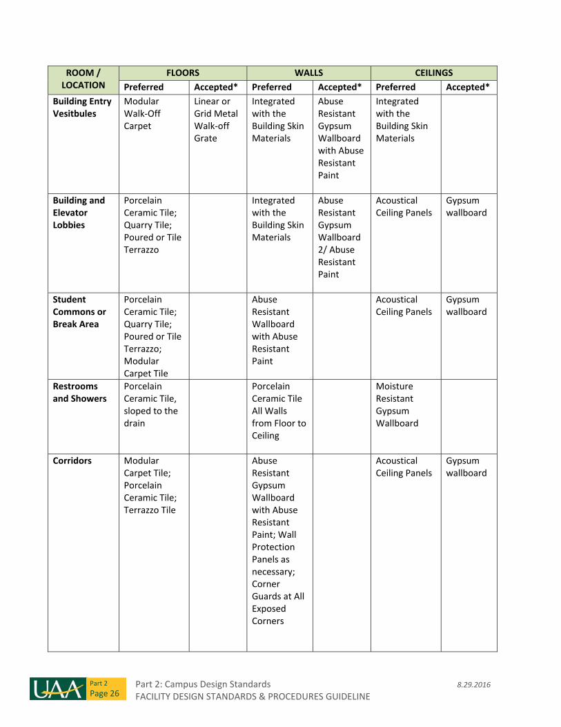
2.27 Floor, Wall, and Ceiling Finishes
Wall material requirements shall be coordinated with UAA FP&C, FMO and the Stakeholder Group early in
the design process. In the absence of special requirements for the project, preferred floor, wall and ceiling
materials are as follows:
Part 2: Campus Design Standards 8.29.2016 FACILITY DESIGN STANDARDS & PROCEDURES GUIDELINE
Part 2
Page 26
ROOM / LOCATION
FLOORS WALLS CEILINGS
Preferred Accepted* Preferred Accepted* Preferred Accepted*
Building Entry Vesitbules
Modular Walk‐Off Carpet
Linear or Grid Metal Walk‐off Grate
Integrated with the Building Skin Materials
Abuse Resistant Gypsum Wallboard with Abuse Resistant Paint
Integrated with the Building Skin Materials
Building and Elevator Lobbies
Porcelain Ceramic Tile; Quarry Tile; Poured or Tile Terrazzo
Integrated with the Building Skin Materials
Abuse Resistant Gypsum Wallboard 2/ Abuse Resistant Paint
Acoustical Ceiling Panels
Gypsum wallboard
Student Commons or Break Area
Porcelain Ceramic Tile; Quarry Tile; Poured or Tile Terrazzo; Modular Carpet Tile
Abuse Resistant Wallboard with Abuse Resistant Paint
Acoustical Ceiling Panels
Gypsum wallboard
Restrooms and Showers
Porcelain Ceramic Tile, sloped to the drain
Porcelain Ceramic Tile All Walls from Floor to Ceiling
Moisture Resistant Gypsum Wallboard
Corridors Modular Carpet Tile; Porcelain Ceramic Tile; Terrazzo Tile
Abuse Resistant Gypsum Wallboard with Abuse Resistant Paint; Wall Protection Panels as necessary; Corner Guards at All Exposed Corners
Acoustical Ceiling Panels
Gypsum wallboard
8.29.2016 Part 2: Campus Design Standards FACILITY DESIGN STANDARDS & PROCEDURES GUIDELINE
Part 2
Page 27
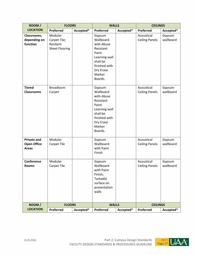
ROOM / LOCATION
FLOORS WALLS CEILINGS
Preferred Accepted* Preferred Accepted* Preferred Accepted*
Classrooms, depending on function
Modular Carpet Tile; Resilient Sheet Flooring
Gypsum Wallboard with Abuse Resistant Paint. Learning wall shall be finished with Dry Erase Marker Boards.
Acoustical Ceiling Panels
Gypsum wallboard
Tiered Classrooms
Broadloom Carpet
Gypsum Wallboard with Abuse Resistant Paint. Learning wall shall be finished with Dry Erase Marker Boards.
Acoustical Ceiling Panels
Gypsum wallboard
Private and Open Office Areas
Modular Carpet Tile
Gypsum Wallboard with Paint Finish
Acoustical Ceiling Panels
Gypsum wallboard
Conference Rooms
Modular Carpet Tile
Gypsum Wallboard with Paint Finish; Tackable surface on presentation walls
Acoustical Ceiling Panels
Gypsum wallboard
ROOM / LOCATION
FLOORS WALLS CEILINGS
Preferred Accepted* Preferred Accepted* Preferred Accepted*
Part 2: Campus Design Standards 8.29.2016 FACILITY DESIGN STANDARDS & PROCEDURES GUIDELINE
Part 2
Page 28
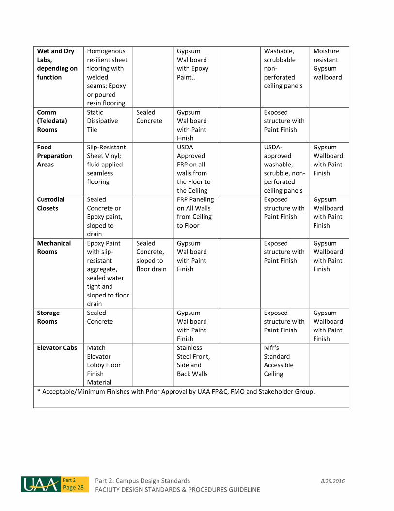
Wet and Dry Labs, depending on function
Homogenous resilient sheet flooring with welded seams; Epoxy or poured resin flooring.
Gypsum Wallboard with Epoxy Paint..
Washable, scrubbable non‐perforated ceiling panels
Moisture resistant Gypsum wallboard
Comm (Teledata) Rooms
Static Dissipative Tile
Sealed Concrete
Gypsum Wallboard with Paint Finish
Exposed structure with Paint Finish
Food Preparation Areas
Slip‐Resistant Sheet Vinyl; fluid applied seamless flooring
USDA Approved FRP on all walls from the Floor to the Ceiling
USDA‐approved washable, scrubble, non‐perforated ceiling panels
Gypsum Wallboard with Paint Finish
Custodial Closets
Sealed Concrete or Epoxy paint, sloped to drain
FRP Paneling on All Walls from Ceiling to Floor
Exposed structure with Paint Finish
Gypsum Wallboard with Paint Finish
Mechanical Rooms
Epoxy Paint with slip‐resistant aggregate, sealed water tight and sloped to floor drain
Sealed Concrete, sloped to floor drain
Gypsum Wallboard with Paint Finish
Exposed structure with Paint Finish
Gypsum Wallboard with Paint Finish
Storage Rooms
Sealed Concrete
Gypsum Wallboard with Paint Finish
Exposed structure with Paint Finish
Gypsum Wallboard with Paint Finish
Elevator Cabs Match Elevator Lobby Floor Finish Material
Stainless Steel Front, Side and Back Walls
Mfr's Standard Accessible Ceiling
* Acceptable/Minimum Finishes with Prior Approval by UAA FP&C, FMO and Stakeholder Group.
8.29.2016 Part 2: Campus Design Standards FACILITY DESIGN STANDARDS & PROCEDURES GUIDELINE
Part 2
Page 29
2.28 Paints and Colors
Paint colors in campus buildings are the responsibility of FP&C and FMO. Individual users and user
groups are prohibited from repainting buildings – interior and exterior, including private offices –
without prior written authorization from the FP&C Director.
UAA intends to limit the amount of interior paint colors that will be used in a facility. A primary
“white” or light colored base paint shall be selected along with no more than three accent colors.
Projects that require additional accent colors shall seek prior approval from the Facilities Director.
The Architect shall specify that the General Contractor is to provide keyed floor plans which
identify all paint colors and their associated locations throughout the building at the end of
construction. The keyed floor plans shall include a schedule of paint formulas identifying paint
type, color, sheen, and number of coats. The keyed floor plans shall be included with the building
O&M manuals and project Record Documents. See Technical Requirements Section 09 90 00 for
additional information.
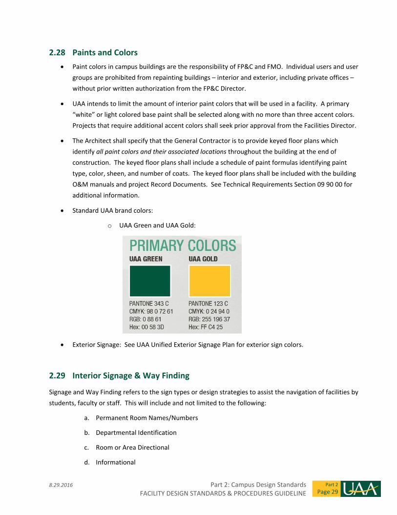
Standard UAA brand colors:
o UAA Green and UAA Gold:
Exterior Signage: See UAA Unified Exterior Signage Plan for exterior sign colors.
2.29 Interior Signage & Way Finding
Signage and Way Finding refers to the sign types or design strategies to assist the navigation of facilities by
students, faculty or staff. This will include and not limited to the following:
a. Permanent Room Names/Numbers
b. Departmental Identification
c. Room or Area Directional
d. Informational
Part 2: Campus Design Standards 8.29.2016 FACILITY DESIGN STANDARDS & PROCEDURES GUIDELINE
Part 2
Page 30
e. Regulatory
f. Evacuation
g. Fire Protection
h. Stair Egress
i. Floor Level Identification
j. Main Building Directories
k. Floor Level Directories
l. Material finishes/colors, architectural elements, woodworking or lighting components
which identify directions or destinations
m. Environmental Graphics which identify destinations
All projects will have permanent room numbers established by the UAA Facilities Planner. It is the
designer’s responsibility to coordinate this process with UAA. All drawings will reference the UAA
approved final room numbering system.
Design interior identification and way finding signage in accordance with UAA Interior Sign Guide
and ADA guidelines and requirements.
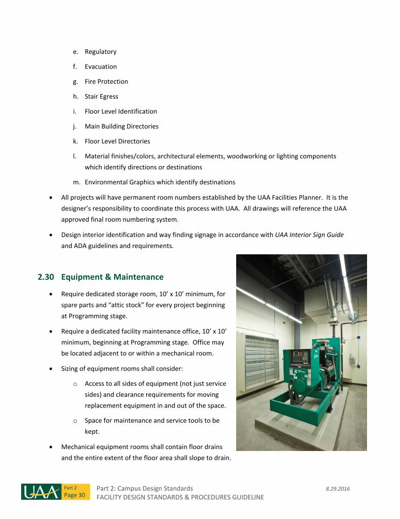
2.30 Equipment & Maintenance
Require dedicated storage room, 10’ x 10’ minimum, for
spare parts and “attic stock” for every project beginning
at Programming stage.
Require a dedicated facility maintenance office, 10’ x 10’
minimum, beginning at Programming stage. Office may
be located adjacent to or within a mechanical room.
Sizing of equipment rooms shall consider:
o Access to all sides of equipment (not just service
sides) and clearance requirements for moving
replacement equipment in and out of the space.
o Space for maintenance and service tools to be
kept.
Mechanical equipment rooms shall contain floor drains
and the entire extent of the floor area shall slope to drain.
8.29.2016 Part 2: Campus Design Standards FACILITY DESIGN STANDARDS & PROCEDURES GUIDELINE
Part 2
Page 31
The perimeter of boiler rooms and other mechanical spaces with fluid‐containing equipment shall
be designed to contain spills.
Enclosed and conditioned rooftop penthouses are preferred over exposed rooftop equipment, as
budget allows. Elevator access to penthouses is encouraged.
See Roof Design for additional equipment and maintenance requirements.
Handheld radios are used for maintenance communications; verify frequencies used by FMO and
provide full coverage within buildings without degradation of signal.
2.31 Restrooms
All public restroom doors shall include automatic handicap push button operators.
At least one universal (non‐gender‐specific/family/private) toilet room is required in new projects and encouraged in renovation projects.
A Lactation/Nursing Mothers Room, 8’x8’ minimum, is required in new projects and encouraged in renovation projects.
Toilet and urinal privacy screens shall be stainless steel.
Porcelain tile will be used for the floor and wall finish. Porcelain tile will be full height on all restroom walls.
Paper towel dispensers are provided by University‐contracted vendor. Dispensers will be mounted to a stainless steel plate integral with a recessed, stainless steel waste dispenser to be specified by the designer.
Soap dispensers at lavatories are provided by University‐contracted vendor.
Lavatory faucets shall be single hole and vandal resistant, hard‐wired, touchless technology.
Toilets will be wall mounted, high‐efficiency and 1.6 gallons per flush, hard‐wired, touchless technology.
Urinals will be wall mounted, high‐efficiency and 1.0 gallons per flush, hard‐wired, touchless technology.
Floor drains are required in every restroom. Entire restroom floor must slope to floor drain.
2.32 Stairs, Elevators & Ladders
Encourage use of stairs over elevators. Design stairs to be open, accessible, and convenient for
users. Stairs that make use of natural light and architectural design to enhance visual interest and
experience are most effective.
Stair treads, risers and landings at interior fire stairs will be slip resistant materials. Treads shall
have contrasting nosings for the visually impaired.
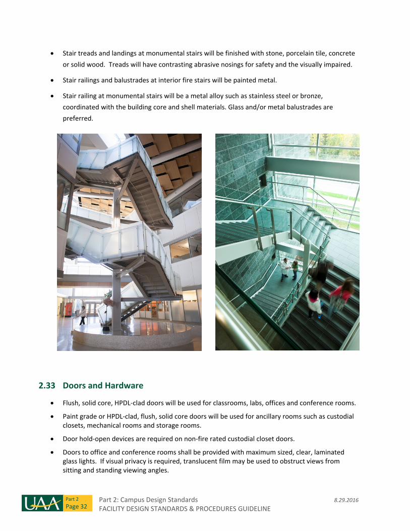
Part 2: Campus Design Standards 8.29.2016 FACILITY DESIGN STANDARDS & PROCEDURES GUIDELINE
Part 2
Page 32
Stair treads and landings at monumental stairs will be finished with stone, porcelain tile, concrete
or solid wood. Treads will have contrasting abrasive nosings for safety and the visually impaired.
Stair railings and balustrades at interior fire stairs will be painted metal.
Stair railing at monumental stairs will be a metal alloy such as stainless steel or bronze,
coordinated with the building core and shell materials. Glass and/or metal balustrades are
preferred.
2.33 Doors and Hardware
Flush, solid core, HPDL‐clad doors will be used for classrooms, labs, offices and conference rooms.
Paint grade or HPDL‐clad, flush, solid core doors will be used for ancillary rooms such as custodial closets, mechanical rooms and storage rooms.
Door hold‐open devices are required on non‐fire rated custodial closet doors.
Doors to office and conference rooms shall be provided with maximum sized, clear, laminated glass lights. If visual privacy is required, translucent film may be used to obstruct views from sitting and standing viewing angles.
8.29.2016 Part 2: Campus Design Standards FACILITY DESIGN STANDARDS & PROCEDURES GUIDELINE
Part 2
Page 33
Doors to classrooms and labs will be provided with a clear glass sidelight.
Access control card readers are preferred for all building entry and classroom doors.
Kick plates are required for all entry doors to departmental suites, classrooms, labs, restrooms, custodial closets, mechanical rooms, and storage rooms.
2.34 Acoustics
Minimum acoustical requirements, sound isolation, and vibration controls are required as high
levels of background noise generated by HVAC equipment, poor room acoustics, or intrusion of
noise from outside the classroom, labs, or office areas can affect concentration. Noise Control as
measured by decibel reduction through partitions and floors shall be thoroughly reviewed during
the design.
Control of sound transmission between rooms is required between classrooms, private offices, and
conference rooms. In those areas the ceilings shall have the following ratings:
o NRC (noise reduction coefficient) – 0.75
o CAC (sound blocking) – 35
o AC (articulation class) – 170
Utilize the most current ASHRAE design guidelines for HVAC related background sound levels.
Generally, provide the following:
o Libraries 35 NC
o Classrooms 35 NC
o Offices 35 NC
o Executive offices with full height walls 30NC
o Corridors and Lobbies 40 NC
o Laboratories 40NC
2.35 Furniture, Furnishings and Equipment
Furniture, Furnishings & Equipment (FF&E) typically have no permanent connection to the
structure of the building or facility utilities. FF&E items are depreciating assets that have a useful
life greater than three years. The type of loose or stationary furnishings and equipment for a
department should be selected to support the educational curriculum as well as the function of
the spaces designed for students, faculty and staff within a facility. The FF&E selected and
specified shall also provide flexibility for relocation and reconfiguration in the future.
Part 2: Campus Design Standards 8.29.2016 FACILITY DESIGN STANDARDS & PROCEDURES GUIDELINE
Part 2
Page 34
The specific FF&E manufacturers and types of products stipulated by UAA will be utilized in order
to support reuse, reduce inventory, and create an economy of scale purchasing, which will provide
UAA with the best possible discounts and value.
The FF&E interior design and acquisition process requires cooperation among all departments and
the UAA Facilities staff. Each project will require a representative from the department who will
serve as the single‐point‐of‐contact and has the authority to make FF&E decisions.
For new construction and renovation projects, the interior design and acquisition process must
begin early on in the project to ensure the FF&E is coordinated with the building infrastructure
requirements–such as internal wall blocking to support wall hung FF&E, power/voice/data
locations, overhead lighting locations and floor load data – and to allow adequate time to select,
specify, procure, manufacture, and install the FF&E.
Finish samples, mock‐ups, or full scale models of some furniture types may be required for review
by UAA. This effort will be facilitated by the designer and the samples and mock‐ups will be
provided by the manufacturer.
The FF&E specifications will include date of specification, manufacturer, quantity, item description,
cost per unit, total item cost, shipping costs, installation costs (if applicable), and total cost. In
addition to the noted information, photo specification sheets and samples of all finishes and
upholstery will be provided as supplemental information.
All electronic office equipment and appliances shall be Energy Star certified products.
The FF&E planner and vendor are responsible for supervising delivery and installation of the FF&E
at the project site. The FF&E planner and vendor shall ensure that materials, finishes, and
furniture are installed according to specifications. A punch‐list will be developed for the
installation and submitted to the FP&C Project Manager. The planner shall work directly with the
furniture vendor and Project Manager to ensure that all punch‐list issues are resolved.
Move management is the responsibility of UAA Facilities Planning & Construction.
Furniture Selection Criteria:
o Classroom furniture will be able to be easily reconfigured by the user to support a
preferred pedagogy.
o All classroom, common, office, and conference room furniture shall be able to support
collaboration and the current technology being used by student, faculty or staff.
o Panel based systems furniture is discouraged and preference will be given towards desk
supported and wall mounted systems.
o Non‐handed casegoods are preferred.
8.29.2016 Part 2: Campus Design Standards FACILITY DESIGN STANDARDS & PROCEDURES GUIDELINE
Part 2
Page 35
o All work and study environments should promote good physical health with attention
given to ergonomically designed seating, adjustable height work surfaces, task lighting,
and computer workspaces.
o All finishes selected and specified for a piece of furniture will be based on its durability and
cleanability.
o All upholstery and furnishings with foam will be tested for compliance to CAL 133.
o Use of Forestry Stewardship Council (FSC) certified wood for wood veneer casegoods is
preferred.
MEP System Design
2.36 Mechanical Systems ‐ General
The design of the mechanical systems should incorporate the following:
o Energy efficiency
o Accessibility of equipment and ease of maintenance
o Consideration for future growth or space configuration modifications
Encourage the inclusion and participation of UAA Facility Maintenance and Operations (FMO) staff
in the system design and commissioning process.
Specify spare parts or components be provided when lead time for these items is lengthy or the
function of the equipment is critical.
Use variable speed drives (VSD) where practical for energy conservation and system control. Use
of two speed motors is not acceptable.
Maintenance access to equipment is of the utmost importance. Maintenance platforms should be
provided for equipment not easily maintainable from a step ladder.
2.37 Heating and Cooling Load Calculations
Utilize the following conditions for calculation of the heating and cooling loads for each building:
o Outdoor Conditions:
Outdoor Heating Design Temperature to be ASHRAE 99.6% Heating Dry Bulb
Temperature for Anchorage/Elmendorf AFB.
Part 2: Campus Design Standards 8.29.2016 FACILITY DESIGN STANDARDS & PROCEDURES GUIDELINE
Part 2
Page 36
Outdoor Cooling Design Condition to be ASHRAE 1% Cooling Dry Bulb Temperature
and Mean coincident wet bulb temperature for Anchorage/Elmendorf AFB.
Outdoor Dehumidification Design Condition to be ASHRAE 1% Cooling Dew Point
Temperature, Humidity Ratios and Mean coincident dry bulb temperature for
Anchorage/Elmendorf AFB.
o Indoor Design Condition:
Heating: 70 +/‐ 2 degrees F indoor design temperature.
Cooling: 74 +/‐ 2 degrees F indoor design temperature.
2.38 Ventilation Systems
Design ventilation systems to meet the requirements of the latest adopted version of ASHRAE
Standards 62.1 and 90.1.
Utilize occupancy sensors where practical to reduce ventilation rates of unoccupied spaces.
Provide demand controlled ventilation strategies for high occupancy spaces such as large
classrooms, laboratories and conference rooms.
Provide filtration of supply air in air handling units to include: MERV 8 pre‐filters in front of MERV
13 final filters.
Provide the maximum level of temperature control zoning afforded by the project budget.
Generally, each classroom and conference room should be zoned separately; each corner office
should be zoned separately and preferably a maximum of two offices of similar size, exposure and
occupancy should share a temperature zone.
Provide a manual filter change On/Off switch for each air handling unit to facilitate filter change
out by Maintenance staff. The switch is wired directly to the supply fan VFD. Install the switch on a
wall as close to the filter section as practical. Label the switch with a permanent placard.
Provide outside air intake louvers sized for a maximum free area velocity of 400 fpm to minimize
entrainment of rain and snow. Slope intake plenums to drain to the exterior. Specify water tight
construction.
Humidification systems are not required nor desired for classrooms, teaching laboratories,
administrative offices or performance spaces. Humidification systems may be required to maintain
required humidity levels in such spaces as archive storage rooms or research and testing rooms
and will be considered on a project by project basis.
8.29.2016 Part 2: Campus Design Standards FACILITY DESIGN STANDARDS & PROCEDURES GUIDELINE
Part 2
Page 37
2.39 Heating Systems
Design heating systems to meet the requirements of the latest adopted version of ASHRAE
Standards 90.1.
Provide building heating plants comprised of multiple boilers for redundancy. Provide a minimum
combined boiler output at 120% of the calculated design heating load.
Provide boiler number and sizing that allows one boiler to be out of service with sufficient heat
capacity to protect the building from damage.
Water with corrosion inhibitors is the preferred hydronic fluid. Provide a water meter with 1‐1/4”
system fill bypass on the system makeup water connection.
Secondary 50% propylene glycol/water systems are to be provided for heating terminal devices
(coils, etc.) that may be exposed to outside air and would be at risk of damage due to freezing.
Provide for manual make‐up for secondary glycol systems. Automatic glycol makeup systems are
not acceptable.
Air elimination systems are to be utilized on all new hydronic heating systems.
Utilize ball or gate valves for equipment isolation valves. Butterfly valves used for this purpose are
not acceptable.
Provide redundant lead/lag pumps for building hydronic heating circulation. Provide a separate
VSD for each pump.
Provide floor level isolation valves at a minimum. Provide for drain down of the system by floor
level at a minimum.
No hydronic piping is to be routed through Electrical or Telecom Rooms.
Coordinate standby power requirements for equipment required for building freeze protection.
2.40 Cooling Systems
Design cooling systems to meet the requirements of the latest adopted version of ASHRAE
Standards 90.1.
Development of new well water cooling systems on campus is not desired.
Air elimination systems are to be utilized on all new hydronic cooling systems.
Utilize ball or gate valves for equipment isolation valves. Butterfly valves used for this purpose are
not acceptable.
Part 2: Campus Design Standards 8.29.2016 FACILITY DESIGN STANDARDS & PROCEDURES GUIDELINE
Part 2
Page 38
Provide redundant lead/lag pumps for building hydronic cooling circulation. Provide a separate
VSD for each pump.
Provide floor level isolation valves at a minimum. Provide for drain down of the system by floor
level at a minimum.
No hydronic piping is to be routed through Electrical or Telecom Rooms.
Provide vapor tight insulation for all piping and valves containing fluids below space dewpoint
temperature.
2.41 Plumbing Systems
For building renovation or renewal projects, prior to reuse of concealed or below grade piping,
perform a condition survey via camera inspection.
Standard slope for storm drain and sanitary waste piping is 1/4” per linear foot.
Provide below grade piping inverts on construction drawings.
Provide a water bottle filling station along with drinking fountains.
Provide exterior freeze proof hose bibs. Coordinate locations and spacing with Architect and
Landscape consultant.
Provide for water supply requirements for the building irrigation system, if planned. Coordinate
with Landscape consultant. Provide Code required backflow protection for irrigation system
interior to the building.
Use of double wall indirect fired domestic water heaters is preferred for domestic hot water
generation.
Provide floor drains in all toilet rooms.
Establish whether connection to an AWWU or UAA owned water line is planned. If the water line
is UAA owned, the water meter must be provided by the Contractor.
Establish whether connection to an Enstar or UAA owned gas utility is planned. If the gas line is
UAA owned, the gas meter and pressure regulator(s) must be provided by the Contractor. Most
UAA gas mains are at 50 psig. Coordinate all planned natural gas work with Enstar.
Provide adequate provision for rainleader heat trace segment replacement.
Utilize ball or gate valves for equipment isolation valves. Butterfly valves used for this purpose are
not acceptable.
No plumbing piping is to be routed through Electrical or Telecom Rooms.
8.29.2016 Part 2: Campus Design Standards FACILITY DESIGN STANDARDS & PROCEDURES GUIDELINE
Part 2
Page 39
2.42 Fire Protection Systems
Provide wet fire protections systems meeting the requirements of NFPA 13 for all buildings.
Provide dry sprinkler heads in vestibules and areas subject to freezing.
Utilize dry or pre‐action systems only when these systems are the only alternative for Code
required protection.
Provide Knox FDC connection caps to prevent vandalism and theft.
No fire protection piping is to be routed through Electrical or Telecom Rooms, except as necessary
to protect the room.
UAA is self‐insured and Factory Mutual (FM) fire protection system design requirements and
equipment certification are not required.
Review of the fire protection system design calculations and shop drawings by UAA prior to
construction is not required.
2.43 Building Automation System
Siemens Building Technologies (SBT) is the current sole provider for Building Automation Systems
(BAS).
All incoming building utilities (water, electricity, gas, heating and cooling utilities, if applicable) are
to be metered with output connection to the BAS.
Provide one BAS workstation computer with the latest version of software installed to provide
access and control of the new building. Connect the workstation to the existing UAA BAS network.
For larger projects provision of a laptop workstation in addition to the desktop workstation is
preferred. Coordinate location of BAS workstation with UAA.
2.44 Electrical Systems ‐ General
The electrical systems provide the infrastructure to support the long term usability of the building.
Therefore, life cycle cost should be considered when planning and designing the electrical systems.
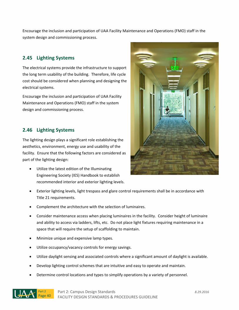
Part 2: Campus Design Standards 8.29.2016 FACILITY DESIGN STANDARDS & PROCEDURES GUIDELINE
Part 2
Page 40
Encourage the inclusion and participation of UAA Facility Maintenance and Operations (FMO) staff in the
system design and commissioning process.
2.45 Lighting Systems
The electrical systems provide the infrastructure to support
the long term usability of the building. Therefore, life cycle
cost should be considered when planning and designing the
electrical systems.
Encourage the inclusion and participation of UAA Facility
Maintenance and Operations (FMO) staff in the system
design and commissioning process.
2.46 Lighting Systems
The lighting design plays a significant role establishing the
aesthetics, environment, energy use and usability of the
facility. Ensure that the following factors are considered as
part of the lighting design:
Utilize the latest edition of the Illuminating
Engineering Society (IES) Handbook to establish
recommended interior and exterior lighting levels.
Exterior lighting levels, light trespass and glare control requirements shall be in accordance with
Title 21 requirements.
Complement the architecture with the selection of luminaires.
Consider maintenance access when placing luminaires in the facility. Consider height of luminaire
and ability to access via ladders, lifts, etc. Do not place light fixtures requiring maintenance in a
space that will require the setup of scaffolding to maintain.
Minimize unique and expensive lamp types.
Utilize occupancy/vacancy controls for energy savings.
Utilize daylight sensing and associated controls where a significant amount of daylight is available.
Develop lighting control schemes that are intuitive and easy to operate and maintain.
Determine control locations and types to simplify operations by a variety of personnel.
8.29.2016 Part 2: Campus Design Standards FACILITY DESIGN STANDARDS & PROCEDURES GUIDELINE
Part 2
Page 41
Control interior lighting fixtures in public and common use spaces via a schedule based lighting
control system with override capability separate from the Building Automation System.
Control exterior lighting fixtures via a schedule based lighting control system with astronomical
time clock separate from the Building Automation System.
2.47 Power Systems
Lay out the power distribution system to support future changes to academic programs and to minimize
home run lengths. Ensure that the following factors are considered as part of the power distribution
system design:
Provide an exterior main disconnect in accordance with the serving utility requirements.
Provide exterior power receptacles in weatherproof enclosures along building perimeter at 75 feet
maximum spacing.
Electrical equipment shall be located in dedicated electrical rooms.
Electrical rooms shall be vertically stacked whenever possible.
Adequately ventilate electrical rooms containing transformers.
Layout panel locations to limit branch circuit homeruns to less than 150 feet wherever feasible.
Size equipment and feeders to support 25% future growth.
Include surge protective devices at main distribution switchboard/panelboard and branch circuit
panels.
Maintain clearance space around electrical equipment for maintenance access.
Include spare conduits stubbed from the exterior of the building into the nearest electrical room.
Minimum size of conduit shall be 1”. Provide a minimum of one conduit on each side of building.
Provide additional conduit(s) to limit the maximum distance between conduits on any side of the
building to 50 feet.
Include spare conduits between electrical rooms on each level of the building. Minimum 2 @ 4”
conduit only.
Include energy monitoring device in the main distribution panel or switchboard. Coordinate any
specific sub metering requirements with UAA during initial design phase.
Include a requirement in the specifications for the contractor to provide Arc Flash Hazard analysis
and calculations in accordance with NFPA 70E. Detailed labels shall be placed on electrical
equipment (Switchboards, Distribution Panels, Panelboards, Transformers, etc.) prior to
Part 2: Campus Design Standards 8.29.2016 FACILITY DESIGN STANDARDS & PROCEDURES GUIDELINE
Part 2
Page 42
substantial completion and shall include flash boundaries, PPE levels, shock hazard level and
approach boundaries.
Include hard wired connections to electric flush valves for plumbing fixtures.
Include a receptacle in sink base cabinets for insta‐hot water dispenser.
All appliances, equipment or assemblies of electrical components that are subject to the adopted
National Electrical Code shall be listed in accordance with Municipality of Anchorage Policy M.01.
2.48 Standby/Emergency Power Systems
Determine whether a standby or emergency generator is required for the facility in coordination with UAA.
Ensure that the following factors are considered as part of the alternate power distribution system design:
Determine whether the generator should be classified as Emergency (NEC Article 700) or Optional
Standby (NEC Article 702).
Determine the fuel source for the generator. Preferred fuel source is diesel. Alternate fuel source
is natural gas. If natural gas is utilized, the generator cannot be classified as an emergency source.
Identify the location for the generator. Preferred location is an interior heated space. Alternate
location is an exterior walk‐in enclosure.
If a standby generator is required, include the following loads on the generator as a minimum:
o Mechanical equipment required for building “freeze protection”.
o Building Automation System panels.
o Lighting and receptacles in mechanical and electrical rooms.
o Minimal lighting in public and common use spaces.
o Telecommunication rooms including any associated HVAC equipment.
o Access control equipment.
o Fire alarm panel.
Additional loads that may be considered for placement on the standby generator include the
following:
o HVAC loads for limited building operation.
o Lighting for limited building operation.
o Receptacles in select areas for limited building operation.
8.29.2016 Part 2: Campus Design Standards FACILITY DESIGN STANDARDS & PROCEDURES GUIDELINE
Part 2
Page 43
If an emergency generator is desired, include the following loads on the emergency branch as a
minimum (standby branch loads should be evaluated as indicated above):
o Life safety egress lighting.
o Fire alarm panel.
2.49 Special Systems
These types of systems evolve quickly and the latest requirements should be confirmed with UAA at the
initial stages of design. The following represents the current design methodology:
TELECOMMUNICATIONS
General:
o Coordinate desired system requirements with the UAA Information Technology Services
(ITS) Department at the initial stage of design.
o Determine main telecom room location to limit horizontal cabling run lengths to a
maximum of 200 feet when routed parallel and perpendicular to building lines.
o Provide a telecom room on each level of the building. Telecom rooms shall be vertically
stacked whenever possible.
o Utilize cable tray in accessible ceiling spaces to collect horizontal cabling and route to
telecom rooms.
o Size telecommunication systems to accommodate 25% growth capacity.
o Provide a telecommunication grounding bus‐bar in each telecom or equipment room in
accordance with the requirements of latest edition of ANSI/TIA/EIA‐607 – Commercial
Building Grounding and Bonding Requirements.
o Routing of other building systems through telecom rooms or equipment rooms is strictly
prohibited unless those systems directly serve the subject telecom room or related
telecommunications systems.
o Ceilings in telecom rooms shall be open to structure. Suspended ceiling are prohibited.
o Provide ¾ inch plywood on all walls of each telecom room or equipment room. Paint
plywood with two coats of intumescent paint. Mount backboard vertically beginning at 12
inches above finished floor.
o Ventilate telecom rooms and/or equipment rooms to maintain a maximum temperature of
75 degrees Fahrenheit. In rooms with sufficient quantities of active, heat producing
equipment, provide supplemental cooling.
Part 2: Campus Design Standards 8.29.2016 FACILITY DESIGN STANDARDS & PROCEDURES GUIDELINE
Part 2
Page 44
o Provide minimum 36 inch wide doors into telecom rooms and equipment rooms. Provide
TR key cores in door locks and/or UAA ITS U card access (access control).
o Provide 50 foot candle minimum lighting levels in telecom rooms and equipment rooms.
o Provide one (1) 120V, 20A, double duplex receptacle every six (6) feet of perimeter wall
length.
Entrance Facilities:
o Design the telecommunication entrance in accordance with the latest adopted edition of
the BICSI TDMM.
o Provide four (4) four inch conduits from the Main Telecom Room to the designed point of
interconnection to the existing University of Alaska – Anchorage backbone cabling system.
Coordinate this point of interconnection and routing of these backbone pathways with
UAA ITS during design.
Main Equipment Room:
o Main Equipment Rooms are typically designed to house large quantities of active
equipment.
o Not all buildings require a Main Equipment Room. Coordinate the need for a Main
Equipment Room with UAA ITS during the initial stages of design.
o Equipment rooms housing large quantities of active equipment may require a dry pipe
sprinkler system and/or a clean agent fire protection system. Coordinate specific
requirements with UAA ITS prior to design.
o Provide four (4) four inch conduits or 24 inch wide cable tray between the Main
Equipment Room and the Main Telecom Room.
Main Telecom Room:
o The Main Telecom Room shall have 13.5 foot by 14 foot minimum dimensions and be sized
to accommodate the placement of eight (8) telecommunication racks.
o Provide four (4) four inch conduits or a 24 inch wide cable tray between the Main Telecom
Room and each satellite Telecom Room.
Satellite Telecom Room(s):
o Satellite telecom rooms shall have 8.5 foot by 14.5 foot minimum dimensions and be sized
to accommodate the placement of four (4) telecommunication racks.
o Provide four (4) four inch conduits or a 24 inch wide cable tray between each satellite
Telecom Room and the Main Telecom Room.
8.29.2016 Part 2: Campus Design Standards FACILITY DESIGN STANDARDS & PROCEDURES GUIDELINE
Part 2
Page 45
Raceways and Cable Tray:
o See the Design Considerations of Division 26.
o Provide a twelve inch wide by four inch deep wire mesh cable tray above each row of
telecom racks.
o Stub each telecom outlet conduit to the nearest cable or directly to the appropriate
telecom room.
o Provide a dedicated conduit for each telecom outlet. Combining cables from multiple
outlets into a single homerun conduit is prohibited.
o Utilize velcro style cable ties in cable tray to organize cables.
o Utilize no more than two (2) ninety degree bends or the equivalent in the telecom
horizontal cable conduits.
o Stub conduit to within 12 vertical inches of the cable tray in the ceiling space.
o Cable tray may be utilized for the routing of other low voltage systems as long as it is sized
to accommodate the telecom cabling and the additional low voltage systems and dividers
are provided to separate the systems.
Telecommunication horizontal cabling:
o Provide Category 6A rated telecom horizontal cabling.
o Provide twelve (12) inches of slack at each telecom outlet.
o Provide plenum rated (CMP) type cable where cabling is routed exposed in cable tray in
plenums.
Telecommunication horizontal cabling:
o Provide patch cords of the same manufacturer as that which provides the telecom
horizontal cabling.
Telecommunication horizontal cabling patch panels and jacks:
o Provide black colored, Category 6A rated, 48 port patch panels with integral strain relief
that encompasses the insulation of the cable at the back of the jack.
o Provide one (1) RU, horizontal wire management beneath each patch panel.
o Provide telecom jacks with eight position, eight conductor (8P8C), and 110 style IDC
termination contacts.
o Terminate each 4 pair cable on an 8P8C modular jack.
o Utilize velcro style cable ties at the back of each patch panel to organize cables.
Part 2: Campus Design Standards 8.29.2016 FACILITY DESIGN STANDARDS & PROCEDURES GUIDELINE
Part 2
Page 46
Telecommunication backbone cabling:
o Provide a twelve strand, 50 micron, enhanced bandwidth multi‐mode (OM3+) fiber optic
cable between the main telecom room and the satellite telecom rooms.
o Provide a twelve strand, 8.3 micron, single‐mode (OS2) fiber optic cable between the main
telecom room and point of connection to the existing UAA ITS backbone cabling. Route via
the entrance facility as noted above.
Telecommunication Racks:
o Provide two post, nominal nineteen inch wide, floor mounted telecom racks in each
telecom room.
o Telecom racks shall be black in color and be 45 rack units (RU) high.
o Provide four inch wide vertical cable management on each side of each telecom rack.
o Adjacent telecom racks can share one vertical cable management unit if the shared
vertical cable management unit is a minimum of six inches wide.
o Provide wall mounted telecom racks only at the request of UAA ITS. Obtain written
permission from UAA ITS prior to using wall mounted telecom racks.
o Provide each telecom rack with a chassis grounding bus‐bar and bond to the telecom room
grounding bus‐bar with a #6 AWG bonding conductor.
a. Provide a surface mounted, 120V, 20A, double duplex receptacle below each telecom rack.
Telecommunications Labeling:
o Provide labeling or telecom horizontal cabling and ports in accordance with BICSI
Standards for a Level 3 or Level 2 Telecom Administrative Standard.
o UAA ITS’ desired labeling follows a standard format indicating floor number and outlet
number and consists of a four digit number where the first digit represent the floor
number and the last digit represents the sequential jack number on that floor. Coordinate
the proposed labeling scheme with UAA ITS prior to issuance of Design Development
Documents.
Telecommunications Testing:
o Telecommunications horizontal cables:
Test each telecom horizontal cable in accordance with the latest edition of the
ANSI/TIA/EIA‐568 standard using a Level III field tester as defined in that standard for
Category 6A rated cable.
8.29.2016 Part 2: Campus Design Standards FACILITY DESIGN STANDARDS & PROCEDURES GUIDELINE
Part 2
Page 47
Test the telecom horizontal cable from the patch panel in the telecom room to the
telecom jack located in the work area using the Permanent Link specification in the
latest edition of the ANSI/TIA/EIA‐568 standard.
All of the installed telecommunications horizontal cables must be tested and must
pass the requirements of the latest edition of the ANSI/TIA/EIA‐568 standard.
Any cable that fails these tests must be diagnosed and corrected. The corrective
action shall be followed with a new test to prove that the corrected link meets the
performance requirements. The final and passing test must be saved and included
in the final test results documentation.
o Telecommunications riser cables:
Test each riser cable in accordance with the latest edition of the ANSI/TIA/EIA‐568
standard for Category 3 rated cable.
o Telecommunications backbone fiber optic cables:
Test each telecom backbone fiber optic cable in accordance with the latest edition
of the ANSI/TIA/EIA‐568 standard.
All of the installed telecom backbone fiber optic cable strands must be tested and
must pass the requirements of the latest edition of the ANSI/TIA/EIA‐568
standard.
Any cable that fails these tests must be diagnosed and corrected. The corrective
action shall be followed with a new test to prove that the corrected link meets the
performance requirements. The final and passing test must be saved and included
in the final test results documentation.
o Telecommunication Documentation:
Provide complete as‐built floor plans in latest AutoCAD format that contain the
following information at a minimum:
Architectural floor plans with finalized room names and numbers.
Location and identification of all voice, data, and fiber optic outlets.
Cable routing. Include a legend on the plans to readily identify the voice, data
and fiber optic cables.
Conduit sizes and routing for all cables installed in conduit.
Cable tray routing and locations.
Bonding and grounding locations.
Part 2: Campus Design Standards 8.29.2016 FACILITY DESIGN STANDARDS & PROCEDURES GUIDELINE
Part 2
Page 48
Large‐scale floor plans of all communications/terminal rooms that indicate
elevation views and plan views of, including but not limited to, all termination
blocks, telecom racks, patch panels, and fiber optic enclosures.
Terminal backboard layout with labeling and pair identification.
Provide two project manuals that are assembled in loose‐leaf binders and contain the
following:
As‐built plans as noted above.
A CD‐ROM or DVD copy of all copper and fiber optic test results, including the
software tools required to view, inspect and print any selection of test reports.
Warranty information and any vendor certification of the installed
infrastructure.
A spreadsheet with telecom port counts and labeling on a per Room basis for
use by UAA ITS.
FIRE ALARM
Typical design shall be a system that meets the minimum code requirements.
System shall communicate alarm and trouble status to UAA University Police Department (UPD)
Central Station.
Include electromagnetic door holders on custodial room doors.
VIDEO SURVEILLANCE
Cameras are furnished by UAA and installed by Contractor.
Coordinate desired camera locations with UAA University Police Department (UPD). Provide two‐
port telecom device at camera locations.
Provide rough‐in and conduit only for future cameras on site lighting poles. Coordinate location of
future cameras with UAA UPD.
ACCESS CONTROL
Provide devices and controllers to support the door hardware specified by the Project Architect
and UAA.
Locate door controllers on the secure side of the door in accessible ceiling space.
8.29.2016 Part 2: Campus Design Standards FACILITY DESIGN STANDARDS & PROCEDURES GUIDELINE
Part 2
Page 49
Site control units (SCUs) will connect via Ethernet to the University’s Access Control server.
Provide a separate site control unit (SCU) for interior access control doors and a separate site
control unit (SCU) for exterior access control doors.
Connect access control equipment and associated door power supplies to standby generator (if
available).
INTRUSION DETECTION
Intrusion detection is currently not in use at the majority of UAA’s facilities. Coordinate specific
project requirements with UAA.
EMERGENCY “BLUE” PHONE
Provide power and telecom at blue phone location(s) specified by UAA. Coordinate locations and
quantities of blue phones with UAA during the initial design phase.
AUDIO‐VIDEO COMMUNICATION
Coordinate specific requirements with UAA Audio/Visual (A/V) Coordinator.
Include the UAA A/V Coordinator in initial design phase meetings.
Small Projects: Provide raceway and boxes to support the systems design as specified by the
Project Architect and UAA. Equipment and cabling will be furnished and installed by UAA A/V
Department.
Larger Projects: Provide raceway, boxes and cabling to support the systems design as specified by
the Project Architect and UAA. Equipment will be furnished and installed by UAA A/V Department.
Open wiring in accessible ceiling spaces is acceptable for A/V cabling.
Coordinate specific cabling requirements with UAA A/V Department throughout the design
process. Reconfirm cabling types prior to installation of cabling.
Projector mounts and powered projection screens shall be specified by architectural.
Responsibility for speaker installation will be determined on a specific project basis.
Allow time in the construction schedule for A/V ceiling work by UAA prior to furniture installation
and cleaning.
Part 2: Campus Design Standards 8.29.2016 FACILITY DESIGN STANDARDS & PROCEDURES GUIDELINE
Part 2
Page 50
EMERGENCY RESPONDER RADIO COVERAGE
Building shall have approved radio coverage for emergency responders within the building based
upon the existing coverage levels of the public safety communications systems at the exterior of
the building in accordance with International Fire Code (IFC) 510 requirements.
Include provisions and pathways in the building design to allow equipment and cabling to be
added after construction to meet the above requirement.
ROOM SCHEDULING DEVICES
Coordinate desired room scheduling device locations and desired product type with UAA. Current
product type is Apple iPad (Owner furnished, Contractor installed).
Provide vandal resistant iPad enclosure.
Provide double gang junction box at +48” above finished floor adjacent to doorway of each room.
Provide telecom horizontal cable with RJ‐45 jack termination coiled in junction box to power room
scheduling device via Power Over Ethernet (PoE). Provide PoE to USB to power room scheduling
device.
2.50 Commissioning
OVERVIEW
The commissioning process is a quality‐focused process for enhancing the delivery of a project. This
process focuses upon verifying and documenting that the commissioned systems and assemblies are
planned, designed, installed, tested, operated, and maintained to meet the Owner’s Project Requirements
(OPR).
The UAA Project Manager will assign the duties of carrying out the Commissioning Process to the project’s
Commissioning Authority (CxA). The CxA is a formally certified entity (i.e. ASHRAE Certified Commissioning
Process Management Professional (CPMP)) who leads, plans schedules and coordinates the commissioning
process. The CxA may be assigned by UAA as a separate independent entity from the A/E design team
through a UAA CxA Term Contract, or as a member of the A/E design team as an additional service.
During project Design Phase, the CxA will prepare the Section 01 91 00 – COMMISSIONING specification
section for inclusion in the project bid documents. The commissioning specification section is written to
meet the intent of the OPR document utilizing the process defined by the commissioning reference
documents modified for the scope of commissioning support services defined and authorized by UAA. The
specification includes:
Commissioning objectives and scope.
Definitions of commissioning team members.
8.29.2016 Part 2: Campus Design Standards FACILITY DESIGN STANDARDS & PROCEDURES GUIDELINE
Part 2
Page 51
Definitions of commissioning terminology.
Description of the commissioning process.
Sample Commissioning Master Equipment and Systems Log.
Sample Pre‐functional (PC) and Functional Performance Test (FC) checklists.
Commissioning Reference Documents include:
1. ANSI/ASHRAE/IES Standard 202 – Commissioning Process for Buildings and Systems
2. SMACNA HVAC Systems Commissioning Manual
COMMISSIONING PROCESS
Variations in project size and complexity, the presence of critical or highly specialized systems and UAA
requirements suggest describing the commissioning process in terms of different “levels” of
commissioning. The UAA Project Manager will define the level of commissioning support to be provided
on an individual project basis to the A/E. The CxA will specify the level of commissioning effort in Section
01 91 00 – COMMISSIONING. Note that some projects may encompass all three levels of the
commissioning process.
The three basic levels include:
Level 1 ‐ Basic Commissioning
Level 1 commissioning is carried out by the Contractor during the construction and acceptance phases of a
project. Level 1 Basic Commissioning is to be utilized for projects without complex systems (e.g., office or
administrative buildings).
Level 2 ‐ Comprehensive Commissioning
Level 2 commissioning is a comprehensive commissioning process and usually starts in the pre‐design or
design phase and extends though construction and acceptance phases of the project. This level of
commissioning has more formal documentation and training requirements and is usually recommended
for a more complex facility (e.g., teaching laboratory, engineering, and science buildings).
Level 3 – Critical Systems Commissioning
Level 3 commissioning is required for systems in critical applications involving life safety, health risks, high
value processing or research. This level of commissioning verifies correct system functional performance
with all specified environmental criteria maintained under the entire range of expected loads and
operations (e.g., research laboratory, other critical spaces).
COMMISSIONING DEFINITIONS
Part 2: Campus Design Standards 8.29.2016 FACILITY DESIGN STANDARDS & PROCEDURES GUIDELINE
Part 2
Page 52
Commissioning Authority (CxA): The person(s) or company responsible, on UAA’s behalf, for verifying that
the commissioning process is properly executed and completed in accordance with the Contract
Documents. The CxA reviews and approves the scope, planning, scheduling, execution, documentation,
training and final completion of the overall commissioning process. The CxA works directly for UAA’s
Project Manager.
Contractors Commissioning Representative (CCR): The Contractor’s representative responsible for
planning, scheduling, managing, executing and documenting the required commissioning activities. The
CCR must be experienced in basic design, operation, installation and testing of HVAC and electrical systems
and must have strong administrative, planning, organizational and communication skills. The primary duty
of the CCR is to oversee the commissioning process. The CxA approves the selection of the CCR.
Contractor’s Commissioning Team: Members of the Contractor’s team responsible for commissioning
activities. These team members include, but are not limited to:
The CCR and designated support staff.
Mechanical and electrical coordinators.
Subcontractors.
Sub‐subcontractors.
Product/System Vendors.
Manufacturer’s Representatives.
Commissioning Master Equipment and System Log: A tabulated list of equipment and systems to be
commissioned as identified in the project Contract Documents.
Pre‐Functional Installation Checklist (PC): A list of equipment inspections and elementary component
tests required for verification of proper installation of equipment. Pre‐functional checklist items include
static inspections and procedures to prepare the equipment or system for initial operation (e.g., belt
tension, oil levels OK, labels affixed, gages in place, sensors calibrated, etc.) and simple testing of
component or system function, (such as measuring the voltage imbalance on a three phase pump motor of
a chiller system). Pre‐functional checklists augment and are combined with the manufacturer’s start‐up
checklist. The CCR field verifies that the pre‐functional checks take place. UAA and CxA may elect to
witness the execution of selected parts of the PC.
Functional Performance Test Checklist (FC): A list of performance tests required to document the proper
performance of the dynamic function and operation of equipment and systems using direct observation
and monitoring equipment methods. The CCR and UAA field verify that the FTs take place. The CxA will
witness the execution of selected functional performance tests. UAA also may elect to witness the
execution of selected parts of the functional performance tests.
Functional Performance Test (FT): Systematic testing of the dynamic function and operation of equipment
and systems using direct observation and monitoring equipment methods. Functional testing includes
dynamic testing of systems under full operation, including interaction with related systems (e.g., the chiller
8.29.2016 Part 2: Campus Design Standards FACILITY DESIGN STANDARDS & PROCEDURES GUIDELINE
Part 2
Page 53
pump is tested interactively with the chiller functions to see if the pump ramps up and down to maintain
the differential pressure setpoint). Systems are tested under various modes, such as during low cooling or
heating loads, high loads, component failures, unoccupied, varying outside air temperatures, fire alarm,
power failure, etc. The systems are run through the control system’s sequences of operation and
components are verified to be responding as stated in the sequences. Functional Performance Tests are
performed after PCs, equipment startups, and Testing, Adjusting and Balancing (TAB) are complete.
Deferred Functional Tests: FTs that are performed later, after substantial completion, due to partial
occupancy, equipment requirements, seasonal requirements, design or other site conditions that disallow
the test from being performed at an earlier date. Only those functional tests pre‐approved by UAA and
the CxA may be deferred.
Functional Completion: Completion of the commissioning activities required by the Contract Documents
prior to Substantial Completion, as defined in Section 00 08 00 – Supplemental General Conditions of the
Construction Contract.
Phased Commissioning: Commissioning that is completed in phases (e.g., by floors or areas) due to the
size of the systems or other scheduling issues, in order minimize total construction time.
Part 2: Campus Design Standards 8.29.2016 FACILITY DESIGN STANDARDS & PROCEDURES GUIDELINE
Part 2
Page 54
THIS PAGE INTENTIONALLY LEFT BLANK
THIS PAGE INTENTIONALLY LEFT BLANK
5.2.2016 Part 3: Technical Requirements FACILITY DESIGN STANDARDS & PROCEDURES GUIDELINE
Division 3
Page 1
Division 3 – Concrete
Section 03 30 00 – Exterior Cast‐in‐Place Concrete
This section includes exterior concrete, formwork, reinforcing, finishing, and curing.
1. Design Requirements
a. Safety
b. Aesthetics
2. Products:
a. All products are per MASS, with additions listed below.
b. Fire lane surfacing – reinforced earth:
i. Geogrid type material or accepted equivalent designed to meet desired vehicle
requirements.
3. Execution:
a. All products are installed per MASS, or per manufacturer’s recommendation.
End of Division 03

Part 3: Technical Requirements 5.2.2016 FACILITY DESIGN STANDARDS & PROCEDURES GUIDELINE
Division 3
Page 2
THIS PAGE INTENTIONALLY LEFT BLANK
5.2.2016 Part 3: Technical Requirements FACILITY DESIGN STANDARDS & PROCEDURES GUIDELINE
Division 4
Page 1
Division 4 – Masonry
Section 04 40 00 – Stone Assemblies
Section includes: stone cladding, adhered tile veneer, and accessories.
1. Performance:
a. Design wall assemblies to receive adhered stone cladding or stone tile veneer to ensure a
maximum deflection limit of L/600.
b. Specify mock‐ups of tile work by General Contractor. Mock‐ups shall be reviewed for
acceptable installation quality standard by the Architect and by FP&C.
2. Products:
a. Adhered tile veneer shall be set using polymer modified, thin‐set mortar.
b. Exterior adhered tile veneer systems shall utilize a waterproofing membrane approved by
the mortar manufacturer.
3. Installation:
a. Natural stone shall be sealed before and after grouting to prevent staining.
4. Warranty:
a. Provide 15‐year total system warranty for exterior adhered tile veneer systems including
adhesives, mortars, grouts, fluid applied waterproofing, and finish materials:
i. From the date of Substantial Completion, and
ii. Stating that the manufacturer shall repair or replace system components that
show evidence of defects, deterioration, or failure.
End of Division 4

Part 3: Technical Requirements 5.2.2016 FACILITY DESIGN STANDARDS & PROCEDURES GUIDELINE
Division 4
Page 2
THIS PAGE INTENTIONALLY LEFT BLANK
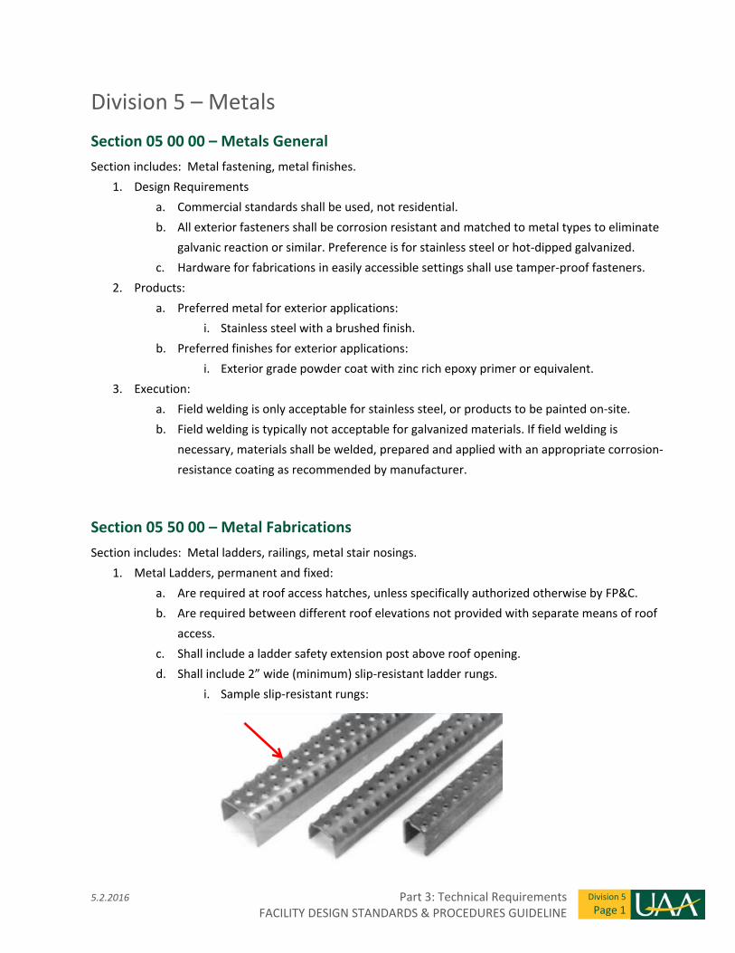
5.2.2016 Part 3: Technical Requirements FACILITY DESIGN STANDARDS & PROCEDURES GUIDELINE
Division 5
Page 1
Division 5 – Metals
Section 05 00 00 – Metals General
Section includes: Metal fastening, metal finishes.
1. Design Requirements
a. Commercial standards shall be used, not residential.
b. All exterior fasteners shall be corrosion resistant and matched to metal types to eliminate
galvanic reaction or similar. Preference is for stainless steel or hot‐dipped galvanized.
c. Hardware for fabrications in easily accessible settings shall use tamper‐proof fasteners.
2. Products:
a. Preferred metal for exterior applications:
i. Stainless steel with a brushed finish.
b. Preferred finishes for exterior applications:
i. Exterior grade powder coat with zinc rich epoxy primer or equivalent.
3. Execution:
a. Field welding is only acceptable for stainless steel, or products to be painted on‐site.
b. Field welding is typically not acceptable for galvanized materials. If field welding is
necessary, materials shall be welded, prepared and applied with an appropriate corrosion‐
resistance coating as recommended by manufacturer.
Section 05 50 00 – Metal Fabrications
Section includes: Metal ladders, railings, metal stair nosings.
1. Metal Ladders, permanent and fixed:
a. Are required at roof access hatches, unless specifically authorized otherwise by FP&C.
b. Are required between different roof elevations not provided with separate means of roof
access.
c. Shall include a ladder safety extension post above roof opening.
d. Shall include 2” wide (minimum) slip‐resistant ladder rungs.
i. Sample slip‐resistant rungs:
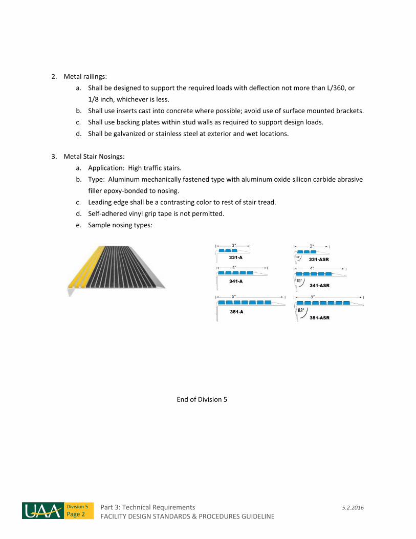
Part 3: Technical Requirements 5.2.2016 FACILITY DESIGN STANDARDS & PROCEDURES GUIDELINE
Division 5
Page 2
2. Metal railings:
a. Shall be designed to support the required loads with deflection not more than L/360, or
1/8 inch, whichever is less.
b. Shall use inserts cast into concrete where possible; avoid use of surface mounted brackets.
c. Shall use backing plates within stud walls as required to support design loads.
d. Shall be galvanized or stainless steel at exterior and wet locations.
3. Metal Stair Nosings:
a. Application: High traffic stairs.
b. Type: Aluminum mechanically fastened type with aluminum oxide silicon carbide abrasive
filler epoxy‐bonded to nosing.
c. Leading edge shall be a contrasting color to rest of stair tread.
d. Self‐adhered vinyl grip tape is not permitted.
e. Sample nosing types:
End of Division 5
5.2.2016 Part 3: Technical Requirements FACILITY DESIGN STANDARDS & PROCEDURES GUIDELINE
Division 6
Page 1
Division 6 – Wood, Plastics, and Composites
Section 06 10 00 – Rough Carpentry
Section includes: Rough carpentry
1. Use of Forestry Stewardship Council (FSC) certified wood is preferred.
2. Fire‐retardant treated wood and preservative treated wood shall be installed with manufacturer
recommended fasteners.
3. Field cut surfaces of preservative treated wood shall be coated with preservative compatible with
factory applied treatment in accordance with manufacturer’s instructions.
Section 06 20 00 – Finish Carpentry
Section includes: Wood door frames, casings, moldings and trims.
1. Use of Forestry Stewardship Council (FSC) certified wood is preferred.
2. Use of northern and western wood species is preferred.
Section 06 40 00 – Architectural Wood Work
Section includes: Architectural millwork, casework, countertops and wall surfacing
Related Requirements: 12 30 00 – Casework
1. Generally, all high pressure plastic laminate (HPDL) casework will be designed, manufactured and
installed in accord with the AWI, Custom Grade standards.
2. Generally, all hardwood and wood veneer woodwork will be designed, manufactured and
installed in accord with the AWI, Premium Grade standards.
3. Use of Forestry Stewardship Council (FSC) certified wood is preferred.
4. Preferred countertop material for all wood veneer or plastic laminate casework is solid surface.
See 06 60 00.
5. All architectural woodwork will be shop finished.
6. Wood Casework Fabrication:
a. Fabricate and install in accord with AWI, Premium Grade standards.
b. Edge banding to be hardwood, minimum 3mm thick.
Part 3: Technical Requirements 5.2.2016 FACILITY DESIGN STANDARDS & PROCEDURES GUIDELINE
Division 6
Page 2
c. Plywood or MDF substrates for the construction of countertops, millwork panels and
casework are required. Particleboard substrates are not permitted.
d. Use full extension, heavy duty, self‐closing drawer slides. Accuride or equal.
e. Use cabinet door silencers, typical.
Section 06 60 00 – Plastic Fabrications
Section includes: Solid Polymer Fabrications (“solid surface”)
1. Locations and preferred uses: window sills, millwork and lavatory counter tops, transaction
surfaces and wall panels.
2. Color and pattern shall be selected by the designer. Solid Surfaces shall be 3/4" thick for
horizontal applications. Backsplashes, where specified, shall be 1/2" thick. Vertical applications
shall be 3/8" thick.
3. Material shall be homogeneous.
4. Materials shall comply to ANSI‐Z‐124.3 & Z124.6, ASTM‐D‐638, ASTM‐D‐790, ASTM‐2583, ASTM‐D‐
1499, ASTM‐84 and NEMA‐LD‐3‐3.10, performance requirements.
Section 06 80 00 – Composite Fabrications
Section includes: Glass Fiber Reinforced Plastic Fabrications
1. Product will be used full height on all walls in food service preparation areas and janitor closets.
2. Materials shall comply to ASTM‐D‐790M‐86, ASTM‐D‐638M‐86b, ASTM‐2583‐87, ASTM E‐84
performance requirements.
3. Thickness: 0.10" (2.5 mm); Panel Width: 4’ (1.22m) Panel Height: Either 8’ or 10’ (2.5m or 3m).
4. Provide welding rods, joint strips, transitions strips, and edge trims.
5. Exposed top edge to be finished with stainless steel strip.
6. Use polyurethane adhesive.
7. Form continuous wall base with resilient floor product and join to FRP wall panel for hygienic wall
installation.
8. Preparation and installation of all FRP systems shall be in compliance with the product
manufacturer’s recommendations and instructions.
End of Division 6
5.2.2016 Part 3: Technical Requirements FACILITY DESIGN STANDARDS & PROCEDURES GUIDELINE
Division 7
Page 1
Division 7 – Thermal and Moisture Protection
Section 07 10 00 – Damp proofing and Waterproofing
Section includes: Bituminous damp proofing, sheet membrane waterproofing, fluid applied waterproofing.
1. Performance:
a. Self‐adhered sheet membrane waterproofing shall be unaffected when tested in
accordance with ASTM D1970 at minus 20 degrees (F), 180 degree bend on a 1 inch
mandrel.
2. Locations:
a. HDPE sheet membrane waterproofing shall be used below elevator pits on all projects, and
below slabs and foundation walls on building sites with high water tables.
b. Any concrete or masonry foundation walls that retain earth and enclose interior spaces
below grade shall be dampproofed – or waterproofed at high water table sites – from the
top of the footing to the finished grade.
3. Damp proofing and waterproofing installations require inspection by FP&C and the A/E prior to
cover or backfill.
Section 07 20 00 – Thermal Protection
Section includes: thermal insulation, exterior insulation and finish systems (EIFS).
1. Fiberglass batt insulation is not permitted at removable ceilings or within roof assemblies.
2. Exterior insulation outboard of wall framing must comply with local code requirements.
3. Exterior heated walkways and interior floors with in‐floor radiant heat must be insulated on the
underside with closed‐cell rigid polystyrene.
4. Exterior Insulation and Finish System (EIFS) is not permitted without prior approval from FP&C.
Section 07 25 00 – Weather Barriers
Section includes: Vapor retarders, air barriers.
1. Performance:
a. Under slab vapor retarders shall have a maximum permeance of 0.01 Perms when tested
in accordance with ASTM E96.
b. Interior vapor retarders shall have a maximum permeance of 0.045 Perms when tested in
accordance with ASTM E96.
Part 3: Technical Requirements 5.2.2016 FACILITY DESIGN STANDARDS & PROCEDURES GUIDELINE
Division 7
Page 2
c. Air/weather barriers shall have a maximum air permeance of 0.004 cubic feet per minute
per square‐foot when tested in accordance with ASTM E2178 and a minimum water vapor
permeance of 5 Perms when tested in accordance with ASTM E96.
d. Air/weather barriers behind exterior rain screen systems shall be high strength, high vapor
permeance air/weather barrier capable of withstanding long term exposure.
2. Products:
a. Air barriers behind rain screen systems:
i. Vapro Shield LLC’s WrapShield,
ii. National Shelter Products, Inc., DRYline HP,
iii. Or pre‐approved equal.
3. Installation:
a. Air/weather barriers shall be installed as a continuous system and integrated with
water/damp proofing, roof membrane, and flexible flashings at openings.
b. Vapor retarders at walls and roofs shall be integrated and installed as a continuous system.
4. Interior vapor retarder installations require inspection by FP&C and the A/E prior to cover.
Section 07 40 00 – Metal Roofing and Siding
Section includes: Preformed metal roofing, Insulated metal wall panels, composite metal wall panels.
Related Requirements: 07 70 00 – Roof Specialties and Accessories
1. Selection of roofing material and roof design strategy shall be coordinated with FP&C.
2. Warranties:
a. Metal Roof Warranty: Metal Roofing manufacturer shall provide 20 year factory‐applied
finish warranty and 5 year weather‐tightness warranty for roof system:
i. From the date of Substantial Completion, and
ii. Stating that the manufacturer shall repair or replace system components that
show evidence of finish degradation and/or that fail to keep out water.
b. Insulated Metal Panel Warranty: Insulated Metal Panel manufacturer shall provide 20
year factory‐applied finish warranty and 10 year weather‐tightness warranty for panels:
i. From the date of Substantial Completion, and
ii. Stating that the manufacturer shall repair or replace panel components that show
evidence of finish degradation and/or failure of water tightness, loss of integrity of
the seals, and/or deflection and buckling.
c. Composite Metal Panel Warranty: Composite Metal Panel manufacturer shall provide 20
year factory‐applied finish warranty and 5 year delamination warranty for panels:
i. From the date of Substantial Completion, and
5.2.2016 Part 3: Technical Requirements FACILITY DESIGN STANDARDS & PROCEDURES GUIDELINE
Division 7
Page 3
ii. Stating that the manufacturer shall repair or replace panel components that show
evidence of finish degradation and/or observable deformation as a result of
delamination of metal skin from the core material.
3. Performance:
a. Metal roofing and siding shall accommodate without deformation anticipated thermal
movement over an ambient temperature range of minus 75 degrees (F) to 100 degrees (F).
b. Metal siding and roofing shall withstand structural loads (dead, live, wind, snow) and shall
accommodate movement caused by the following without damage to the system,
components, or seals:
i. Normal movement
ii. Seasonal temperature cycling
iii. Deflection of the structural support framing
c. Metal siding and roofing shall be factory finished with finish system suitable to meet
warranty requirements. Field finishing of new products is not permitted.
Section 07 50 00 – Membrane Roofing
Section includes: Ethylene‐Propylene‐Diene‐Monomer (EPDM) Roofing; cover board, rigid roof insulation,
roof sheathing.
Related Requirements: 07 25 00 – Weather Barriers (vapor retarders)
07 70 00 – Roof Specialties and Accessories
1. Selection of roofing material and roof design strategy shall be coordinated with FP&C.
2. Low‐slope roofs must drain to internal roof drains; parapet scuppers are not permitted.
3. Roof protection is required along routes between roof access and rooftop equipment; adhered
walkway pads are preferred over roof pavers.
4. Warranty: Roofing manufacturer shall provide 20 year total roof assembly warranty:
a. From the date of Substantial Completion, and
b. Stating the manufacturer shall repair or replace defective materials if the roofing systems
leaks or allows insulation beneath the membrane to become wet during the entire
warranty period.
5. UAA FP&C’s standard low‐slope roof system consists of (top to bottom):
a. Fully‐adhered EPDM membrane roofing, 60 mils thick, white.
b. Cover board – gypsum fiber roof board, mechanically fastened.
c. Insulation ‐ Expanded polystyrene, R‐40 minimum.
d. Vapor retarder, see 07 25 00.
e. Roof sheathing – exterior glass mat gypsum sheathing, Type X.
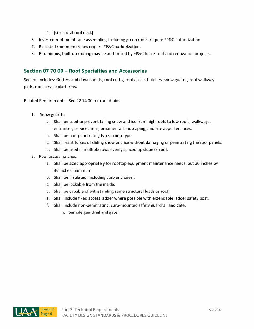
Part 3: Technical Requirements 5.2.2016 FACILITY DESIGN STANDARDS & PROCEDURES GUIDELINE
Division 7
Page 4
f. [structural roof deck]
6. Inverted roof membrane assemblies, including green roofs, require FP&C authorization.
7. Ballasted roof membranes require FP&C authorization.
8. Bituminous, built‐up roofing may be authorized by FP&C for re‐roof and renovation projects.
Section 07 70 00 – Roof Specialties and Accessories
Section includes: Gutters and downspouts, roof curbs, roof access hatches, snow guards, roof walkway
pads, roof service platforms.
Related Requirements: See 22 14 00 for roof drains.
1. Snow guards:
a. Shall be used to prevent falling snow and ice from high roofs to low roofs, walkways,
entrances, service areas, ornamental landscaping, and site appurtenances.
b. Shall be non‐penetrating type, crimp‐type.
c. Shall resist forces of sliding snow and ice without damaging or penetrating the roof panels.
d. Shall be used in multiple rows evenly spaced up slope of roof.
2. Roof access hatches:
a. Shall be sized appropriately for rooftop equipment maintenance needs, but 36 inches by
36 inches, minimum.
b. Shall be insulated, including curb and cover.
c. Shall be lockable from the inside.
d. Shall be capable of withstanding same structural loads as roof.
e. Shall include fixed access ladder where possible with extendable ladder safety post.
f. Shall include non‐penetrating, curb‐mounted safety guardrail and gate.
i. Sample guardrail and gate:
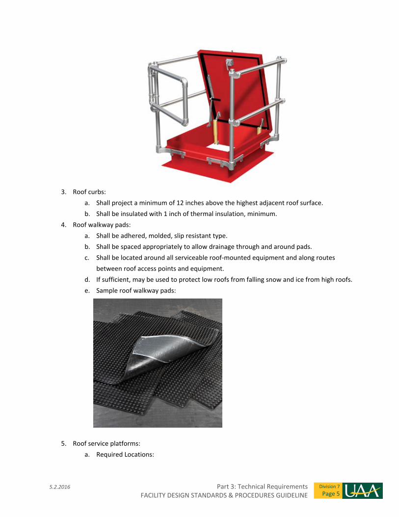
5.2.2016 Part 3: Technical Requirements FACILITY DESIGN STANDARDS & PROCEDURES GUIDELINE
Division 7
Page 5
3. Roof curbs:
a. Shall project a minimum of 12 inches above the highest adjacent roof surface.
b. Shall be insulated with 1 inch of thermal insulation, minimum.
4. Roof walkway pads:
a. Shall be adhered, molded, slip resistant type.
b. Shall be spaced appropriately to allow drainage through and around pads.
c. Shall be located around all serviceable roof‐mounted equipment and along routes
between roof access points and equipment.
d. If sufficient, may be used to protect low roofs from falling snow and ice from high roofs.
e. Sample roof walkway pads:
5. Roof service platforms:
a. Required Locations:
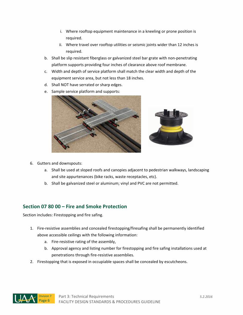
Part 3: Technical Requirements 5.2.2016 FACILITY DESIGN STANDARDS & PROCEDURES GUIDELINE
Division 7
Page 6
i. Where rooftop equipment maintenance in a kneeling or prone position is
required.
ii. Where travel over rooftop utilities or seismic joints wider than 12 inches is
required.
b. Shall be slip resistant fiberglass or galvanized steel bar grate with non‐penetrating
platform supports providing four inches of clearance above roof membrane.
c. Width and depth of service platform shall match the clear width and depth of the
equipment service area, but not less than 18 inches.
d. Shall NOT have serrated or sharp edges.
e. Sample service platform and supports:
6. Gutters and downspouts:
a. Shall be used at sloped roofs and canopies adjacent to pedestrian walkways, landscaping
and site appurtenances (bike racks, waste receptacles, etc).
b. Shall be galvanized steel or aluminum; vinyl and PVC are not permitted.
Section 07 80 00 – Fire and Smoke Protection
Section includes: Firestopping and fire safing.
1. Fire‐resistive assemblies and concealed firestopping/firesafing shall be permanently identified
above accessible ceilings with the following information:
a. Fire‐resistive rating of the assembly,
b. Approval agency and listing number for firestopping and fire safing installations used at
penetrations through fire‐resistive assemblies.
2. Firestopping that is exposed in occupiable spaces shall be concealed by escutcheons.
5.2.2016 Part 3: Technical Requirements FACILITY DESIGN STANDARDS & PROCEDURES GUIDELINE
Division 7
Page 7
Section 07 90 00 – Joint Protection
Section includes: Joint Sealants.
1. Joint sealants shall be installed only at air and substrate temperatures above 40 degrees (F).
2. Exterior sealants shall accommodate joint movements resulting from temperatures ranging from
minus 35 degrees (F) to 100 degrees (F).
End of Division 7

Part 3: Technical Requirements 5.2.2016 FACILITY DESIGN STANDARDS & PROCEDURES GUIDELINE
Division 7
Page 8
THIS PAGE INTENTIONALLY LEFT BLANK
5.2.2016 Part 3: Technical Requirements FACILITY DESIGN STANDARDS & PROCEDURES GUIDELINE
Division 8
Page 1
Division 8 ‐ Openings
Section 08 10 00 – Doors and Frames
Section includes: Metal doors and frames, wood doors, plastic laminate doors, composite doors.
Related Requirements: 08 70 00 ‐ Hardware
1. Flush wood door cores shall be lumber, agrifiber‐plastic, or structural composite lumber non‐
formaldehyde only products.
2. Hollow‐core doors are not permitted.
3. Natural wood veneer doors shall be Custom with grade A faces, minimum.
4. High pressure decorative laminate (HPDL) veneer or galvanized steel painted doors shall be used at
locations requiring frequent cleaning or disinfection.
5. Exterior doors and frames shall be insulated and thermally‐broken
6. Knock‐down (KD) door frames are not permitted without prior approval from FP&C.
Section 08 30 00 – Specialty Doors and Frames
Section includes: access doors and panels, overhead coiling doors, overhead sectional doors.
1. Access Doors:
a. Access doors and panels for valve access by hands and arms only must be a minimum
of 12”x12”; 16”x16” is preferred.
b. Access doors and panels for entry of maintenance personnel must be a minimum of
24” x 30”; 36”x36” is preferred.
c. Access to shut‐offs must be labeled, “EMERGENCY X SHUT‐OFF”.
d. At secured or restricted access locations, or locations concealed from public view,
access shall be possible by hand‐actuated quarter turn tee‐handle; removal of multiple
screws is not acceptable.
e. For locations exposed to public view, doors shall have keyed cylinder locking device.
i. All such access doors shall be keyed alike.
f. Access doors and panels in wet locations, including restrooms and janitor’s closets,
shall be stainless steel.
g. Plastic access doors or panels are not permitted.
2. Coiling Doors: Overhead coiling doors over 8 feet wide shall be power operated.
3. Sectional Doors: Overhead sectional doors shall be power operated.
Part 3: Technical Requirements 5.2.2016 FACILITY DESIGN STANDARDS & PROCEDURES GUIDELINE
Division 8
Page 2
Section 08 40 00 – Entrances, Storefronts and Curtain Walls
Section includes: Glazed curtain wall assemblies, glazed storefront assemblies, glazed entrance doors,
automatic entrance doors.
Related Requirements: 08 80 00 ‐ Glazing
1. Automatic sliding entrance door assemblies:
a. Shall be emergency break‐away type, unless specifically approved otherwise by FP&C.
b. Acceptable manufacturers:
i. Stanley Access Technologies.
ii. Horton Automatics.
iii. Dorma Group.
iv. Or pre‐approved equal.
2. Glazed curtain wall and storefront assemblies:
a. Exterior glazed curtain wall and storefront frames shall be thermally broken anodized
aluminum.
b. Exterior curtain wall and storefront doors shall be thermally broken and accommodate 1” insulated glazing.
c. Exterior glazed aluminum curtain wall assemblies shall have the following minimum
performance characteristics:
i. Condensation Resistance Factor of Glass and Framing: 78, minimum, measured in
accordance with AAMA 1503.
ii. Air Leakage: 0.06 cubic feet/min/square‐foot of wall area, maximum, measured in
accordance with ASTM E283.
iii. No uncontrolled water on indoor face when test in accordance with ASTM E331,
pressure differential of 10 lbf/sqft.
iv. Overall U‐value including glazing: 0.39 Btu/(hr sqft degF), maximum.
Section 08 50 00 – Windows
Section includes: Aluminum windows, wood windows, vinyl windows, fiberglass windows, service
windows.
Related Requirements: 08 80 00 ‐ Glazing
1. Exterior window frames shall be thermally broken.
5.2.2016 Part 3: Technical Requirements FACILITY DESIGN STANDARDS & PROCEDURES GUIDELINE
Division 8
Page 3
a. Overall U‐value including glazing: 0.39 Btu/(hr sqft degF), maximum.
2. Exterior frames shall accommodate 1” insulated glazing units, minimum.
3. Operable windows shall be avoided; seek authorization from FP&C prior to including operable
windows and/or passive ventilation in design.
a. Where used, first floor operable windows shall have 4 inch opening limitation stops.
Section 08 60 00 – Roof Windows and Skylights
Section includes: unit skylights, metal‐framed skylights. 1. Skylights must be designed to withstand all structural loads; coordinate selection with structural
engineer.
2. Fabricate skylights to maintain continuous air and vapor barrier throughout assembly, with barrier
plane aligned with inside pane of glazing.
3. Skylights must include interior drainage channels which drain to the exterior.
4. Skylight curbs must be 18 inches minimum above adjacent roof surface.
Section 08 70 00 – Hardware
Section includes: Door hardware, access control hardware.
1. UAA FMO maintains a list of standard campus door hardware. Consult with FMO prior to
developing door hardware specifications.
2. Cylinders shall be Large Format Interchangeable Core cylinders.
a. Provide 6‐pin E keyway for all cylinders unless directed otherwise by UAA.
3. Mortise Locks and latch sets shall conform to ASI/BHMA A156.13, Series 1000, minimum Grade 1.
4. Standard Classroom locks shall be single cylinder non‐deadbolt, with inside thumb turn and
automatic unlocking (example: Schlage L9056, 06 lever with L‐face trim).
5. Standard finish: satin stainless steel.
6. Electrified, card‐access Classroom locks shall include a manual wall push button inside the room
that automatically secures the classroom door(s).
7. Thresholds shall be mill finish extruded aluminum, saddle type, and must comply with ADA and
ANSI 117.1‐2003.
8. Exterior main entry doors and heavy‐use doors shall have continuous hinges.
9. Center mullions at interior and exterior double doors, where used, shall be key‐removable.
10. Door swing:
a. Doors immediately adjacent to walls and other building components shall swing open 95
degrees minimum.
Part 3: Technical Requirements 5.2.2016 FACILITY DESIGN STANDARDS & PROCEDURES GUIDELINE
Division 8
Page 4
b. Doors with overhead stops shall swing open 100 degrees minimum.
11. Acoustical doors shall have automatic door bottom seals and gasketing.
12. Electronic Access Control hardware must interconnect to fire detection and alarm systems.
13. ADA automatic pushbutton actuators are required at all public restroom doors.
14. All magnetic holders must release upon activation of an alarm.
15. Power Supplies for electric locks shall include battery back‐up.
Section 08 80 00 – Glazing
Section includes: Glazing and glazing accessories.
1. Exterior glazing shall be 1” thick insulated glazing units meeting the following performance
requirements:
a. NFRC winter nighttime U‐Value: 0.24 maximum
b. Solar heat gain coefficient (SHGC) : 0.35 maximum
c. Light to Solar Gain ratio (LSG): 1.4 minimum.
2. Exterior glazing sealants shall accommodate joint movements resulting from temperatures ranging
from minus 35 degrees (F) to 100 degrees (F).
3. Exterior sealants shall be installed only at air and substrate temperatures above 40 degrees (F).
End of Division 8
8.29.2016 Part 3: Technical Requirements FACILITY DESIGN STANDARDS & PROCEDURES GUIDELINE
Division 9
Page 1
Division 9 ‐ Finishes
Section 09 20 00 –Gypsum Board
Section includes: Gypsum board assemblies, non‐structural metal framing.
1. Provide gypsum panel products with 100% recycled paper faces and maximum recycled core
content, and no measurable quantities of mercury or mercury compounds.
2. Abuse resistant gypsum board shall be used at high traffic public areas including corridors and
lobbies up to a height of 96 inches above floor.
a. National Gypsum’s “Hi‐Abuse XP Gypsum.”
b. USG Corporations’s “Fiberock Brand VHI (Very High Impact) Gypsum.”
c. Or pre‐approved equal.
3. Moisture resistant glass‐mat faced gypsum board shall be used at interior wet/damp locations and
areas subject to humidity and/or moisture contact including toilet rooms, janitor’s closets, rooms
housing fluid conveying machinery and equipment, mechanically humidified spaces, etc.
a. Mechanically humidified spaces shall include vapor retarders in perimeter walls, ceilings,
and floors (as necessary) in accordance with 07 25 00.
4. Gypsum wallboard control joints shall be located no more than 30 feet apart.
a. Clearly identify control joint locations in public areas on Drawings and/or specifications.
b. Field coordinate additional control joint locations during construction.
5. Non‐structural metal framing for interior walls and ceilings shall be designed with a deflection limit
of L/360, or as required for the intended finish, whichever is more stringent.
6. Backing is required at all wall mounted equipment, fixtures, and furniture (anticipated during
design and construction).
7. Gypsum board finish shall be in accordance with Gypsum Association’s GA‐214‐10, Levels of
Gypsum Board Finishing.
a. In occupied spaces, finish shall be level 4 minimum.
b. In accessory spaces such as mechanical, electrical, janitor closets, etc. level 3 is acceptable.
Section 09 30 00 – Tiling
Section includes: Ceramic, stone, and glass tiling.
1. UAA preferred floor tiles:
a. Glazed quarry tile
b. Unglazed porcelain Ceramic Tile
c. Natural Stone
Part 3: Technical Requirements 8.29.2016 FACILITY DESIGN STANDARDS & PROCEDURES GUIDELINE
Division 9
Page 2
2. UAA preferred wall tiles:
a. Glazed porcelain ceramic tile
3. Sizes of floor tiles are not limited but shall not inhibit slope to floor drains.
4. Sizes of wall tiles are not limited.
5. Install tiles in accordance with most current version of the Tile Council of North America (TCNA)
Handbook.
6. Where possible, specify preformed corners and trim pieces.
7. Use sanded grout for floor applications and unsanded grout at wall applications. Grout should be
sealed per manufacturers recommendations at showers and floors.
8. Provide raised thresholds where tile meets a dissimilar flooring material.
9. Tile substrates are to be moisture/mold/mildew resistant. Refer to GA‐238‐03 for guidelines for
prevention of mold growth on gypsum wallboard.
10. Use a waterproofing membrane at showers and other water intensive areas.
11. Provide floor drains where necessary.
12. Provide drawing details of shower base and install tile to achieve positive drainage.
13. Provide 5% attic stock of tile for each quality and color of tile installed.
Section 09 50 00 – Ceilings
Section includes: Acoustical ceilings
1. Suspension systems shall be Class A, 15/16” grid face, heavy‐duty, hot‐dipped galvanized with
baked paint finish. Specify stainless steel or aluminum finish suspension systems for high humidity
locations. Provide wall angles and splices for complete installation.
2. 24” x 48” acoustical ceilings are preferred for adequate maintenance access. Seek authorization
from FP&C prior to including 24” x 24” acoustical ceilings in design.
3. Concealed spline ceiling systems are not permitted.
4. Painted acoustical ceiling panels are not permitted.
5. Ceilings installed in laboratories, food preparation areas and clean rooms should be an inorganic
product with a non‐perforated surface resistant to the growth of mold, mildew, and bacteria;
washable, scrubbable, soil‐resistant and resistant to chemical fumes.
6. Coordinate ceiling tile selection with the lighting system. When using indirect lighting systems,
select ceilings with light reflectance values of .89 or higher. For direct and indirect lighting
applications provide ceilings with light reflectance values of .80 or higher.
7. Specify ceiling panels with consideration to acoustical performance. Total control of sound
transmission between rooms is required between classrooms, private offices and conference
rooms. In those areas the ceilings shall have the following ratings:
a. NRC (noise reduction coefficient) – 0.75
8.29.2016 Part 3: Technical Requirements FACILITY DESIGN STANDARDS & PROCEDURES GUIDELINE
Division 9
Page 3
b. CAC (sound blocking) – 35 c. AC (articulation class) – 170
Section 09 60 00 – Flooring
Section includes: Flooring treatment, wood flooring, resilient flooring, fluid‐applied flooring, carpeting.
1. General: All exposed concrete slabs not receiving additional floor coverings shall be sealed with
penetrating sealer.
2. Carpet:
a. Modular carpet tile is preferred over roll or broadloom stock.
b. Two types of carpet are preferred.
i. Carpet‐1 will typically be used for classrooms, corridors, and office type spaces.
ii. Carpet‐2 will typically be used in building entry vestibules.
c. All carpet shall be CRI Green Label Plus certified.
d. Preference is to use carpet with a high recycled content and high recyclability using
current technology.
e. Specify overage/attic stock of carpet tile equivalent to 5% of total carpet area.
Carpet 1‐ Construction:
a. Color and Pattern:
i. Solid colors shall be avoided; a mixed pattern and texture with high soil and stain
hiding capabilities is preferred.
ii. Carpet shall be tufted, loop pile. Printed carpets shall be avoided.
iii. Carpet colors will coordinate with standard wall colors.
b. Carpet Fiber:
iv. 100% Invista Type 6,6 or Solutia Type 6,6 nylon.
c. Carpet Dye Method:
v. 100% solution dyed.
Carpet 2‐ Construction:
a. Color and Pattern:
vi. Solid colors shall be avoided; a mixed pattern and texture with high soil and stain
hiding capabilities is preferred.
vii. Carpet shall be non‐woven, diagonal or textured pattern loop
viii. Carpet colors will coordinate with standard wall colors.
b. Carpet Fiber:
ix. 100% polypropylene or 100% type 6,6 Nylon
c. Carpet Dye Method:
x. 100% solution dyed.
Part 3: Technical Requirements 8.29.2016 FACILITY DESIGN STANDARDS & PROCEDURES GUIDELINE
Division 9
Page 4
3. Flooring Adhesives:
a. Use adhesives with the following limits for VOC content:
i. Rubber Floor and Base Adhesives: Not more than 25 g/L.
ii. Cove Base Adhesives: Not more than 25 g/L
iii. Ceramic Floor and Wall Tile Adhesives: 2 g/L
b. Preference for modular carpet tile installation is a “no glue installation” by connecting the
carpet modules together. The connectors shall contain no liquid components and shall
have “zero” calculated VOC’s.
c. Adhesives for broadloom carpet must contain antimicrobial preservative and have “zero”
calculated VOC’s.
4. Rubber Base:
a. 100% rubber content is preferred.
b. 1/8” gauge.
c. For carpeted areas use a 4” height, no‐toe profile.
d. For resilient floor area use a 4” height, standard cove profile.
e. Base will be manufactured in 120’ coils. Corners will be formed in the field.
5. Resilient Flooring:
a. Rubber tiles or sheet goods are preferred.
b. Composite rubber/cork resilient flooring is an acceptable option.
c. Slip resistant fully welded sheet vinyl flooring is preferred in food preparation areas.
d. Provide integrated contrast strip for strip tread visibility
e. Tile size:
i. 2’‐0” x 2’‐0” x 3mm thickness
f. Sheet size:
i. 6’‐0” x 35’‐0”‐ 45’‐0” length x 3mm thickness
g. Meet the performance requirements of ASTM F 1859, Type I, Standard Specification for
Rubber Sheet Floor Covering without backing.
h. Prepare subfloor and install in accord with the manufactures requirements.
6. Wood Flooring:
a. Generally wood flooring will be limited in use and only for stages, gymnasium and possibly
in upgraded portions of office areas.
b. Wood athletic flooring will meet the performance requirements of an Anchored Resilient
Floor System, per EN‐14904 Standards
c. Wood flooring for auditoriums and office type spaces will be solid wood ¾” thickness x 3
¼” width x random length. Install nailed to ¾” plywood subfloor.
d. Northern hard maple is preferred specie of wood. First grade maple will be specified and
flooring will be installed to comply with Maple Flooring Manufacturers Association
(MFMA) standards.
8.29.2016 Part 3: Technical Requirements FACILITY DESIGN STANDARDS & PROCEDURES GUIDELINE
Division 9
Page 5
7. Fluid Applied Flooring:
a. Evaluate level of duty (light industrial/moderate industrial/severe industrial) required to
determine system, components and process to specify.
b. Provide factory mixed coatings.
c. Prepare subfloor and install in accord with the manufactures requirements.
8. Terrazzo Flooring:
a. Two types of terrazzo flooring are acceptable: Modular terrazzo tiles and poured terrazzo.
b. Modular terrazzo tiles shall be composed of a combination of resin, recycled glass and
recycled aggregates.
c. Poured terrazzo will be poured in place on new or existing concrete. The type of system to
be specified (i.e. epoxy, sand cushion or bonded) shall be determined by the project
performance requirements, budget, existing conditions, and aesthetics.
Section 09 70 00 – Wall Finishes
Section includes: Wall coverings
1. Textile Wallcovering :
a. Use of vinyl wallcoverings is discouraged.
b. High performance, textile wallcoverings are preferred. These products will be woven,
durable and easily cleaned. Fibers will be either polyester, vinyl coated polyester or
polyethylene.
c. If other types of wallcovering are considered then provide UAA Facilities with the
maintenance procedures for their review and approval.
d. Review scope of wallcovering application with UAA Facilities on a room by room basis to
determine if this type of finish is warranted.
2. Specialty wall finishes which require special expertise, equipment, or non‐readily available
products are discouraged.
Section 09 80 00 – Acoustical Treatment
Section includes: Acoustical panels.
1. For areas which require acoustical wall products the designer will engage an acoustical engineering
consultant to determine performance requirements.
2. Three types of products are preferred and will be used appropriate to the room or space in which
they are installed, as follows:
a. Gymnasium: Rigid acoustical panels
Part 3: Technical Requirements 8.29.2016 FACILITY DESIGN STANDARDS & PROCEDURES GUIDELINE
Division 9
Page 6
b. Auditoriums and Large Lecture rooms: Perforated wood veneer panels
c. Meeting Rooms: Field fabricated stretched fabric acoustical/tackable fabric panels
3. Rigid acoustical Panels:
a. Constructed of a composite core construction of dimensionally stable rigid fiberglass of
medium 6‐7 PCF density, laminated to a 1/16” resilient perforated co‐polymer face sheet.
Thickness will be determined by acoustical performance requirements.
b. Square edge profile
c. Mount panels using aluminum Z‐Clips.
4. Perforated wood panels:
a. Consisting of a perforated dark low VOC medium density fire rated fiberboard (MDF) with
a ribbed natural wood veneer laminated to the face and an acoustically transparent black
mat laminated to the back side. The plank is cut to fit on site and is typically installed on
wood or steel furring (610mm) 24"o.c. with insulation placed behind the panel. The plank
has a tongue and groove edge which is blind nailed to wood or screwed to steel furring
channel mounting clips (supplied) to create a monolithic looking joint.
b. Panel face profiles and wood veneer specie will be determined by the designer and
submitted to UAA Facilities for approval.
c. Standard factory stain finish is preferred.
5. Field fabricated stretched fabric acoustical/tackable fabric panels:
a. Stretched fabric panel system shall consist of continuous perimeter and butt seam
mounting extrusions, site‐fabricated, and applied directly to substrate.
b. Facing fabric shall be stretched over core materials, leaving fabric floating above core
surface. Fabric facing application shall not utilize adhesives, nails, tacks, screws, or tapes.
Nails, tacks, screws or similar items shall not be installed through facing fabric to secure
panel.
c. System shall allow for removal and replacement of fabric facing from individual panels.
Removal of fabric shall provide access to surface behind fabric, without dismantling,
removal, or replacement of mounting extrusions or core material.
d. Thickness of panel will be determined by acoustical performance requirements.
e. Size and profile of reveals between panels will be determined by the designer.
f. Core material will be multi‐density fiberglass and have acoustical as well as tackable
properties and capabilities.
g. Stretched fabric covering will have same performance and material requirements set forth
under textile wallcoverings.
6. All acoustical panels shall have a Class “A” fire rating in accordance with ASTM E‐84 with a flame
spread of 25 or less.
7. Preparation and installation of all acoustical panels shall be in compliance with the product
manufacturer’s recommendations and instructions.
8.29.2016 Part 3: Technical Requirements FACILITY DESIGN STANDARDS & PROCEDURES GUIDELINE
Division 9
Page 7
Section 09 90 00 – Painting and Coating
Section includes: Painting and coatings.
1. Standard campus interior wall paint is professional quality, zero VOC, interior latex.
a. Sherwin Williams ProMar 200 Zero VOC.
b. Bejamin Moore & Co. Ultra Spec 500.
c. PPG Architectural Finishes, Inc. Dulux Ultra Zero VOC.
d. Or pre‐approved equal.
2. Standard campus interior trim/frame paint is professional quality, low VOC acrylic.
a. Sherwin Williams ProClassic Waterbased Acrylic‐Alkyd
b. Bejamin Moore & Co. ADVANCE Waterborne Interior Alkyd.
c. PPG Architectural Finishes, Inc. SpeedHide WB Alkyd.
d. Or pre‐approved equal.
3. Paint color selection process shall comply with process described in Part 1of these Standards.
4. Prepare all surfaces and materials and apply in accordance with the paint manufactures
application instructions.
5. Specify one primer and two finish coats, minimum, for each surface.
6. Paint wall surfaces behind permanently fixed equipment or furniture with prime coat.
7. Prime or seal the edges, ends, faces, undersides and backsides of wood, including cabinets,
counters, cases and paneling.
8. Back‐prime paneling where masonry, plaster or other wet wall construction occurs on backside.
9. Seal tops, bottoms and cutouts of unprimed wood doors.
10. Finish exterior doors on tops, bottoms and side edges the same as exterior faces.
11. Preferred Paint Types and Sheens for Identified Substrates:
a. Painted Doors: Semi‐gloss alkyd.
b. Handrail Systems: Semi‐ gloss alkyd.
c. Animal Rooms: Full gloss alkyd, waterproof epoxy systems
d. Glassware Washing Rooms: Full gloss alkyd, waterproof epoxy systems
e. Sterilizing/Autoclave Rooms: Full gloss alkyd.
f. Office Walls: Eggshell interior latex system.
g. Classroom Walls: Eggshell interior latex system.
h. Typical Lab Walls: Eggshell interior latex system.
i. Corridor Walls: Eggshell interior latex system.
j. Interior Masonry Walls: Block filler and Eggshell interior latex.
k. Interior Metal Doors/Frames: Semi‐gloss alkyd.
l. Interior Wood: Polyurethane; satin finish
Part 3: Technical Requirements 8.29.2016 FACILITY DESIGN STANDARDS & PROCEDURES GUIDELINE
Division 9
Page 8
12. Specify General Contractor to provide keyed floor plans which identify all paint colors and their
associated locations throughout the building at the end of construction. The keyed floor plans
shall include a schedule of paint formulas identifying paint type, color, sheen, and number of
coats. The keyed floor plans shall be included with the building O&M manuals and Record
Documents at project close out.
13. Communicate to Stakeholder Group via FP&C that individual building users and user groups are
prohibited from repainting building interiors – including private offices – without prior approval
from the FP&C Director.
End of Division 9
5.2.2016 Part 3: Technical Requirements FACILITY DESIGN STANDARDS & PROCEDURES GUIDELINE
Division 10
Page 1
Division 10 ‐ Specialties
Section 10 10 00 – Information Specialties
Section includes: Visual display surfaces, signage
1. Visual Display Surfaces:
a. All classrooms and meeting rooms should be provided with porcelain steel marker boards
with required blocking for installation.
b. Marker‐boards: Porcelain enamel writing surface on 24‐gage steel facer skin for dual
magnetic feature, backer skin and high quality core construction. Specify matte finish for
marker‐boards where glare issues may cause visibility problems.
c. Avoid use of sliding marker/tack/display boards. Hardware is a maintenance problem.
d. Avoid use of dry erase painted coatings. Vinyl dry‐erase wall covering is preferred.
e. Tack‐boards: Bound within an aluminum frame, fabric covered board surface on composite
cork/hardboard core.
2. Interior Signage: See UAA Interior Sign Guide.
a. Prepare complete interior signage plans and specifications in accordance with UAA Interior
Sign Guide.
b. UAA FP&C shall assist in developing signage schedule, room names and room numbers.
3. Exterior Signage: See UAA Unified Exterior Signage Plan
a. Buildings must be identified (name and number) in accordance with the UAA Unified
Exterior Signage Plan.
b. Architect, with assistance from FP&C, shall determine best location for building
identification signage.
c. UAA FP&C shall assist in determining building names and numbers.
Section 10 20 00 – Interior Specialties
Section includes: Toilet compartments, toilet accessories, folding panel partitions, wall and corner guards.
1. Toilet partitions shall be Type 304 stainless steel, floor/pedestal mount with continuous hinges on
doors.
a. Wall and ceiling hung partitions are not permitted.
b. Urinal screens may be wall mount.
2. Toilet accessories:
a. Finish shall be Type 304 stainless steel.
Part 3: Technical Requirements 5.2.2016 FACILITY DESIGN STANDARDS & PROCEDURES GUIDELINE
Division 10
Page 2
b. UAA contracts with a vendor to supply paper towel dispenser and soap dispensers.
Architect should identify locations for dispensers on plans and elevations and provide
backing in walls.
c. Electric hand dryers are not permitted.
d. Touchless infrared lavatory faucets are required: see Division 22.
e. Waste receptacles shall be stainless steel and located adjacent to paper towel dispensers
and adjacent to restroom doors.
3. Wall Protection:
a. Corner guards – or other protection –are required at all gypsum wallboard partitions in
hallways, corridors, public lobbies and high traffic areas.
i. Height: 48 inches, minimum; 96 inches preferred at high traffic and service areas.
ii. Corner guards may be stainless steel, or impact resistance PETG plastic with
aluminum retainers.
iii. Plastic Corner guards shall have an NFPA Class A fire rating and be GREENGUARD
certified and comply with ASTM‐256, Impact Resistance of Plastic.
b. Continuous wall protection is required at service entrances and locations where frequent
use of wheeled carts, tables, and dollies is likely to occur.
c. Chair rails – or other protection – are required at class rooms with unfixed seating and
tables.
Section 10 40 00 – Safety Specialties
Section includes: fire extinguisher cabinets, defibrillator cabinets
1. Fire extinguishers located in public areas shall be housed in cabinets.
2. Fire extinguisher cabinets:
a. Shall be stainless steel with clear tempered safety glass or polycarbonate lite.
b. Shall be equipped with battery operated anti‐theft alarms.
c. Shall be clearly identified with lettering on the face of cabinet door.
3. Automatic external defibrillator cabinets:
a. Shall be provided in all campus projects.
b. Shall be stainless steel with clear tempered safety glass or polycarbonate lite.
c. Shall be equipped with battery operated anti‐theft alarms.
d. Shall be clearly identified with lettering on the face of cabinet door.
5.2.2016 Part 3: Technical Requirements FACILITY DESIGN STANDARDS & PROCEDURES GUIDELINE
Division 10
Page 3
Section 10 50 00 – Storage Specialties
Section includes: Lockers, storage shelving
1. All shelving shall be seismically secured to the building structure, wall, or systems furnishings to
prevent tipping.
2. All shelving designed to hold hazardous materials including laboratory chemicals shall include 2
inch seismic lips on open sides and ends.
3. Storage shelving for food shall be stainless steel open wire shelving.
4. Lockers shall be identified with number plates.
End of Division 10
Part 3: Technical Requirements 5.2.2016 FACILITY DESIGN STANDARDS & PROCEDURES GUIDELINE
Division 10
Page 4
THIS PAGE INTENTIONALLY LEFT BLANK
5.2.2016 Part 3: Technical Requirements FACILITY DESIGN STANDARDS & PROCEDURES GUIDELINE
Division 11
Page 1
Division 11 ‐ Equipment
Section 11 40 00 – Food Service Equipment
Section includes: Food storage and preparation equipment; ice machines.
1. Food preparation and storage equipment shall be Type 304 stainless steel, No. 4 finish.
2. All powered food service equipment shall be UL listed.
3. A Food Service Consultant will be engaged to provide programming, design, documentation and
construction administration services for dining hall and commercial kitchen projects.
4. Food service equipment for faculty or administrative break areas shall include:
a. Full height Refrigerator/Freezer
b. Microwave Oven
c. Dishwasher
d. Undercounter ice maker
e. Garbage Disposal
f. Coffee/Tea Brewer
g. Air carafes for meeting room beverage service
Section 11 50 00 – Educational and Scientific Equipment
Section includes: Laboratory equipment, hazardous storage cabinets.
1. Laboratory Equipment:
a. Fumehood manufacturer construction and installation shall be in conformance with and
recognized by Scientific Equipment & Furniture Association (SEFA), and meet SEFA 8
performance standards for durability, structural integrity, and containment.
b. Hoods: Fume hood types to be selected per recommend SEFA and ASHRAE specific
purpose applications. VAV restricted bypass ventilation type is preferred for new
construction.
c. Fumehoods shall pass ASHRAE 110 field containment test.
d. Alarms: Fumehood face velocity and low static pressure alarms are required.
e. Hoods are required to be system UL listed and prewired.
f. Plumbing fixtures shall be pre piped remote fixture type with vacuum breaker.
g. Fumehood Liners shall be modified epoxy, glass reinforced polyester, stainless steel, or
phenolic resin.
h. Fumehood counter tops shall be epoxy resin or stainless steel as required by application.
Part 3: Technical Requirements 5.2.2016 FACILITY DESIGN STANDARDS & PROCEDURES GUIDELINE
Division 11
Page 2
i. Light fixtures shall be vapor proof and electrical outlets shall be explosion proof where
applicable.
j. Fire Extinguisher: Fumehoods shall include dedicated self‐contained fire suppression
system.
2. Hazardous storage cabinets
a. Acid or corrosive Cabinets require mechanical venting or direct venting into fumehood.
(see Metal Casework Division 12 30 00)
b. Flammable or solvent storage cabinets shall be grounded, but shall not be vented with
plugs left in place
c. All solvent storage cabinets are to be OSHA compliant and meet NFPA Code 30 and must
be independently fire tested and approved by FM Global.
Section 11 80 00 – Collection and Disposal Equipment
Section includes: Recycling and solid waste disposal equipment
1. Designate program space for interior waste and recycling stations for all new projects; identify
space on floor plans.
2. Where possible, design built‐in enclosures (i.e. casework) to house interior garbage and recycling
bins.
3. Coordinate with FP&C and FMO to determine appropriate bin capacity for each station.
4. Standard campus exterior garbage and recycling bins: See 12 93 00.
5. Standard campus interior garbage and recycle bins: vendor provided.
End of Division 11
7.21.2016 Part 3: Technical Requirements FACILITY DESIGN STANDARDS & PROCEDURES GUIDELINE
Division 12
Page 1
Division 12 ‐ Furnishings
Section 12 20 00 – Window Treatments
Section includes: Windows blinds, Window shades.
1. To control glare perimeter windows will be provided with roller shades
2. Roller shades will be manually controlled or integrated with automatic electronic room scene
controls.
3. A dark value color for the shade cloth will be provided to enhance view to the outside when shade
is closed.
4. Shade material will be woven, non‐PVC extruded fiber which meets cradle‐to‐cradle criteria. Use
appropriate openness factor to control sunlight.
Section 12 30 00 – Casework
Section includes: Manufactured metal casework, Metal laboratory casework, specialty casework,
countertops.
1. Metal Lab casework system types to be considered:
a. Fixed floor
b. Frame and core with mobile or cantilevered cabinets
c. Table based with mobile cabinets
d. Mobile workstations with mobile cabinets
2. Service distribution in conjunction with case work systems shall be horizontal raceway, service
uprights, service carries, or ceiling service panels.
3. Casework manufacturer, construction and installation shall be in conformance with and
recognized by Scientific Equipment & Furniture Association (SEFA), and meet SEFA 8 performance
standards for durability and structural integrity.
4. Metal casework used in wet areas to be constructed of type 304 Stainless Steel.
5. Metal casework finish to be electrostatically applied powder coated chemical and abrasion
resistant paint.
6. Wood Finish: Synthetic varnish system. Formulation shall meet all SEFA 8 requirements.
7. Steel Door construction shall include:
a. Two‐piece door construction painted before assembly. Structurally sound deadened.
b. 5‐knuckle institutional type stainless steel hinge, 2‐1/2" high.
c. Positive latching mechanism.
d. Rubber door bumpers.
8. Steel Drawer construction shall include:
Part 3: Technical Requirements 7.21.2016 FACILITY DESIGN STANDARDS & PROCEDURES GUIDELINE
Division 12
Page 2
a. Full extension drawer with lock open feature. Self‐closing, with extra‐heavy duty drawer
slides, typical.
b. Interchangeable, interlocking drawer head, sound deadened.
c. One piece drawer body with radiused bottom.
d. Radiused cold rolled steel drawer suspension.
e. Nylon tired, stainless steel ball bearing drawer rollers.
9. Wood Door and Drawer Fronts shall be:
a. 3/4" Birch or Maple banded door with hardwood veneer or,
b. GREENGUARD certified high‐pressure laminate laminated to 100% pre‐consumer recycled
wood fiber cores.
10. Keying and label holders: Coordinate keying and label holder requirements with UAA.
11. Hazardous storage cabinets: See 11 50 00.
12. Laboratory Counter tops to be 1” thick with 4” backsplashes unless directed otherwise. Counter
material to be selected based on application.
a. High pressure laminate or chemical resistant
b. Epoxy resin
c. Phenolic resin
d. Stainless steel
13. Casework for mailrooms should offer sort modules that lock to a frame or stand alone and are
available with open backs and doors. Provide products with sorting shelves, reader stations that
accommodate a computer monitor, bulk sorting units for larger packages, consoles to support sort
modules or to stand alone, sorting work surfaces, credenzas, storage units, bookcases and
overhead units.
Section 12 40 00 – Furnishings and Accessories
Section includes: Entrance floor mats and frames, floor grilles and gratings
1. Entrance floor mats shall be modular walk‐off carpet as specified in Division 9. These will be used
at building entrances to remove remnants of dirt and moisture.
2. Avoid the use of floor grilles due to damage caused by wheeled loads and difficulty in cleaning.
Section 12 50 00 – Furniture
Section includes: Seating, Institutional Furniture
1. The required quality level for a project’s furnishings is identified when the budget is established.
The facility’s intended purpose, in part, determines which quality level is appropriate for its
furnishings.
7.21.2016 Part 3: Technical Requirements FACILITY DESIGN STANDARDS & PROCEDURES GUIDELINE
Division 12
Page 3
2. The designer will confirm with UAA facilities any prior national purchasing agreements or contracts
with furniture manufacturers which may be active. Selections and specifications for new furniture
will be limited to those manufacturers unless there is a need for a specialized product which is not
available through a contracted manufacturer.
3. Fixed classroom seating shall be designed with manufactured, integral horizontal beams for future
installation of data transmission or power cables. Unless directed otherwise, each seat shall be
provided with oversized folding tablet‐arm writing surface for placement of laptop computers.
Tablet‐arm support arms shall be heavy duty.
4. Approximately 8% of tablet‐arms shall be configured for comfortable use by left‐handed persons.
5. Seats shall be upholstered.
6. Arm rests shall be wood or solid plastic, not laminate and without cup holders.
7. Tablet arm tops shall be plastic laminate finish.
8. Classrooms with fixed, continuous work surfaces and seats will be provided with modesty panels.
9. Provide open spaces in fixed seating/table classrooms to comply with ADA requirements for
wheelchair accessibility.
10. Power modules:
a. Integral power modules shall be 6‐1/4” long x 3” wide x 2‐1/2” high. Module shall be
constructed of polycarbonate with textured finish, meeting UL‐VO minimum
requirements.
b. Each power module shall have one duplex receptacle (110 volts).
c. The power module shall have a positive locking device in open position. Shall be
constructed for use with eight wire harness.
d. Eight Wire Harness shall be constructed from flexible conduit to distribute power between
power modules and the power in‐feed. The wire harness shall be enclosed in a plastic
trough. The trough shall be .06 inch thick rigid pvc and attached to underside of table
surfaces.
Section 12 93 00 – Exterior Site Furnishings
Section includes: Product information for ashtrays, benches, bicycle racks, bicycle lockers, bus shelters, dog
refuse stations, dumpster screens, litter bins, shelters, bollards, removable bollards, anti‐skateboard
attachments.
1. Design Standards:
a. Aesthetics
b. Safety
2. Products:
a. General
Part 3: Technical Requirements 7.21.2016 FACILITY DESIGN STANDARDS & PROCEDURES GUIDELINE
Division 12
Page 4
i. For each category below, performance‐based criteria are provided, or two product
options are listed with an allowance for use of a pre‐accepted equivalent.
a. Bench
i. Manufacturer: Landscape Forms
1. Model: Arcata, backed with arms
a. Provide proportion of benches with backs and arms to meet ADA
recommendations.
2. Attachment: Surface mount
3. Finish: Powder coat, color: silver, IPE hardwood slats
ii. Manufacturer: Forms and Surfaces
1. Model: Trio Bench
a. Backed, armrests. 6’ length
2. Attachment: Surface Mount
3. Finish: Powder coat, aluminum texture and IPE hardwood slats
iii. Or pre‐approved equal.
b. Bicycle rack
i. Surface Mounted:
1. Manufacturer: HuntCo
a. Model: SC Bike Rack
b. Attachment: Surface mount
c. Finish: Hot Dipped Galvanized
2. Manufacturer: Palmer group LLC/Bikeparking.com
a. Model: Welle Circular
b. Attachment: Surface mount
c. Finish: Hot Dipped Galvanized
3. Or pre‐approved equal.
ii. Freestanding:
1. Manufacturer: Global Industrial
a. Model: 8‐Bike Stadium Bike Rack (Ready to Assemble). WY269320
b. Finish: Black Powdercoat
2. Manufacturer: Creative Pipe/SCH Enterprises LLC
a. Model: Gauntlet GL Series Bike Racks GL‐4 with channel base
runner
b. Finish: Hot Dipped Galvanized
3. Or pre‐approved equal.
c. Bus shelter
i. Manufacturer: Daytech Limited
7.21.2016 Part 3: Technical Requirements FACILITY DESIGN STANDARDS & PROCEDURES GUIDELINE
Division 12
Page 5
1. Model: ACC05X12N.Perf – ‘Contemporary’ Barrel Roof Transit Shelter,
6’x12’
2. Attachment: Surface mount
3. Finish: Varies within model.
ii. Manufacturer: Duo‐Gard
1. Model: Barrel Vault 6’ x 12’
2. Attachment: Surface mount
3. Finish: Varies within model.
iii. Or pre‐approved equal.
d. Dumpster screen shall:
i. Be of similar design and materials to match adjacent building or design elements.
ii. Have size verified with desired use and scheduled maintenance
e. Litter bin
i. Manufacturer: Forms and Surfaces
1. Model: Cordia with rain cover
2. Attachment: Surface Mount
3. Finish: Powdercoat: aluminum texture, Jatoba slats
ii. Manufacturer: Landscape Forms
1. Model: FGP Litter
2. Attachment: Surface Mount
3. Finish: Anodized aluminum with Ipe slats
iii. Or pre‐approved equal.
f. Bollards
i. Metal:
1. Manufacturer: Reliance Foundry
a. Model: R‐8460, 36” height
b. Attachment: Surface mount
c. Finish: Stainless steel
2. Manufacturer: Creative Pipe/SCH Enterprises LLC
a. Model: Round bollard, 4” I.D. sched 40 pipe with inset reveal
b. Attachment: Embedded
c. Finish: Stainless steel with flat stainless steel top.
3. Or pre‐approved equal.
ii. Wood / Recycled Plastic Lumber:
1. Manufacturer: Bedford Technology
a. Model: Selectforce 8x8 plastic lumber. Chamfered top.
b. Attachment: Embedded. 3.5’ below grade, 2.5’ above gade.
c. Finish: Brown, high density 100% recycled polyethylene plastic
Part 3: Technical Requirements 7.21.2016 FACILITY DESIGN STANDARDS & PROCEDURES GUIDELINE
Division 12
Page 6
2. Manufacturer: Aztec Plastic Lumber
a. 8x8 plastic lumber. Chamfered top.
b. Attachment: Embedded. 3.5’ below grade, 2.5’ above gade.
c. Finish: Brown, high density 100% recycled polyethylene plastic.
3. Or pre‐approved equal.
iii. Vehicular Bollard:
1. Type will depend on use. Typical use would be galvanized schedule 80
concrete‐filled pipe, with optional paint to match site or architectural
colors.
g. Removable Bollards
i. Removable:
1. Manufacturer: Reliance Foundry
a. Model: R‐8902, 36” height
b. Attachment: Removable
c. Finish: Stainless steel
2. Manufacturer: Calpipe Security Bollards
a. Model: SSR05040, Internal Locking Removable Bollards
b. Attachment: Removable
c. Finish: Stainless steel
3. Or pre‐approved equal.
ii. Hinged/Fold‐Down:
1. Manufacturer: Reliance Foundry
a. Model: R‐8902, 36” height
b. Attachment: Fold –down mounting (hinged at base)
c. Finish: Stainless steel
2. Manufacturer: Traffic Guard Direct, Inc.
a. Model: Trafficguard® round post [HRP] 36” height
b. Attachment: Fold –down mounting (hinged at base)
c. Finish: Yellow powdercoat.
3. Or pre‐approved equal.
h. Anti‐skateboard attachments
i. Manufacturer: The Park Catalog
1. Model: 161‐1060, 161‐1010 or with radius to match corner of wall
2. Attachment: Surface mount
3. Finish: Galvanized
ii. Manufacturer: Skate Stoppers
1. Model: FR .12, FR .5, FR1.0, or with radius to match corner of wall
2. Attachment: Surface mount
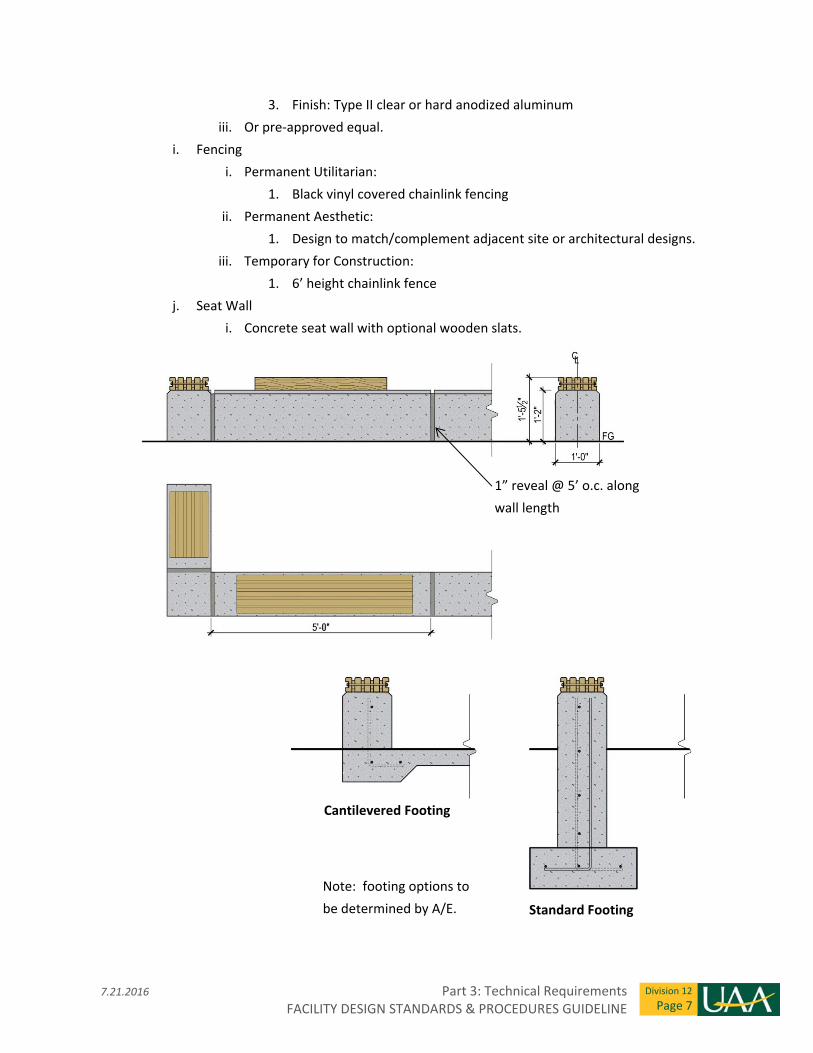
7.21.2016 Part 3: Technical Requirements FACILITY DESIGN STANDARDS & PROCEDURES GUIDELINE
Division 12
Page 7
3. Finish: Type II clear or hard anodized aluminum
iii. Or pre‐approved equal.
i. Fencing
i. Permanent Utilitarian:
1. Black vinyl covered chainlink fencing
ii. Permanent Aesthetic:
1. Design to match/complement adjacent site or architectural designs.
iii. Temporary for Construction:
1. 6’ height chainlink fence
j. Seat Wall
i. Concrete seat wall with optional wooden slats.
Cantilevered Footing
Standard Footing
1” reveal @ 5’ o.c. along
wall length
Note: footing options to
be determined by A/E.

Part 3: Technical Requirements 7.21.2016 FACILITY DESIGN STANDARDS & PROCEDURES GUIDELINE
Division 12
Page 8
End of Division 12
5.2.2016 Part 3: Technical Requirements FACILITY DESIGN STANDARDS & PROCEDURES GUIDELINE
Division 13
Page 1
Division 13 – Special Construction
Section 13 0 00 – Vibration & Seismic Control
Section includes: Vibration and Seismic Design Requirements for non‐structural elements and equipment.
1. This section specifies performance requirements for the design, provision, supervision, and
administration for all aspects of vibration isolation, and seismic control of non‐structural elements.
The design intent is to seismically anchor, brace, and support the facility’s non‐structural elements,
including pre‐engineered equipment, to the building’s structure.
2. Items that require seismic consideration include: mechanical and electrical equipment including
pre‐engineered equipment, health and high hazard items, bookcases, file cabinets including rolling
and compact files, hanging artwork, and storage cabinets – especially cabinets containing
flammable, noxious, or hazardous materials.
a. Mechanical and electrical equipment, including pre‐engineered equipment, includes piping
and ductwork systems, electrical raceways, tanks, vessels, flues, roof mounted, pad
mounted, and exterior and interior equipment, racks, and cabinets.
b. Health and high hazard items are considered to be any closed system containing toxic,
corrosive, refrigerant, flammable, oxidizing, oxygen reduction, combustibles, flue gases,
gas or liquid which poses a health hazard if released into the environment.
3. Either the A/E or the General Contractor via the A/E project specifications will obtain the services
of specialized and qualified manufacturing and seismic design firms to design the overall vibration
control and seismic restraint systems for the non‐structural mechanical and electrical elements of
the project in accordance with the International Building Code.
4. Seismic design requirements for non‐structural components may be by performance specification
and deferred submittals to the AHJ. On small projects, seismic requirements for non‐structural
components by be undertaken by the A/E.
5. Building and site information is to be identified in the construction documents to include wind
speed and exposure, Seismic Occupancy Category, Seismic Design Category, Site Class, and if the
building is an Essential Facility.
a. The seismic design data is usually shown on the structural drawings. When no structural
drawings are included project requirements can be included elsewhere on construction
drawings.
Part 3: Technical Requirements 5.2.2016 FACILITY DESIGN STANDARDS & PROCEDURES GUIDELINE
Division 13
Page 2
6. Life safety and high hazard systems and equipment are to be identified in the construction
documents. When Component Important Factor of 1.5 is required, it will be identified on the
construction drawings.
7. IBC special inspection requirements (periodic and continuous) are to be identified in construction
documents and coordinated with UAA.
8. Deferred submittals are to be identified in the construction documents and coordinated with UAA.
9. Seismic and wind load analysis submittal requirements: Alaska registered professional structural
engineering calculations, drawings, and details, and product information shall be submitted to and
approved by the Authority Having Jurisdiction and the Structural Engineer of Record.
10. California Office of Statewide Health Planning and Development, OSHPD, bracing systems having a
current anchorage pre‐approval "OPA" number shall be submitted with information on usage and
capability to resist seismic forces noted as applicable when used for a project.
11. Equipment with factory mounted internal vibration and seismic restraint devices shall meet the
vibration and seismic control requirements of this section.
12. Building seismic joints and systems required to accommodate differential seismic motion are to be
identified in the construction documents.
13. Coordination of non‐structural element attachment techniques and design loads with the project’s
structural design Engineer of Record is required.
14. General seismic restraint requirements
a. Provide taut seismic cable assemblies or single rigid arm braces on non‐vibration isolated
systems.
b. For vibration isolated systems, avoid short circuiting of isolated equipment and piping.
Provide slight amount of slack seismic cable assemblies or resilient single arm braces for
vibration isolated systems.
c. Do not mix solid bracing with cable bracing in the same direction on any run.
d. Provide flexible connections or design accommodations in pipes, ducts, and raceways
where they cross seismic joints, where adjacent sections or branches are supported by
different structural elements, and where the connections terminate with connection to
equipment that is anchored to a different structural element from the one supporting the
connections as they approach equipment.
e. Coordinate attachments to roof curbs, rails, or posts for connections for seismic load, wind
load, and vibration control.
5.2.2016 Part 3: Technical Requirements FACILITY DESIGN STANDARDS & PROCEDURES GUIDELINE
Division 13
Page 3
f. Coordinate exterior and interior reinforced concrete pads and curbs for resisting seismic
and wind loads, and vibration mitigation. Install base mounted equipment on reinforced
concrete housekeeping pads or reinforced concrete pads for exterior equipment properly
sized and doweled or expansion shielded to the deck to meet acceleration design criteria.
Extend pads beyond equipment base rails/floor mounting plates to meet anchor
embedment requirements. Anchor equipment to housekeeping pads in accordance with
certified and approved anchoring details. See Division 3 for concrete requirements and
coordinate with Sections 20 0529 and 26 0529 Hangers and Supports for mechanical and
electrical equipment, respectively.
End of Division 13
Part 3: Technical Requirements 5.2.2016 FACILITY DESIGN STANDARDS & PROCEDURES GUIDELINE
Division 13
Page 4
THIS PAGE INTENTIONALLY LEFT BLANK
5.2.2016 Part 3: Technical Requirements FACILITY DESIGN STANDARDS & PROCEDURES GUIDELINE
Division 14
Page 1
Division 14 – Conveying Equipment
Section 14 20 00 – Elevators
Section includes: Electric traction and hydraulic elevators.
1. UAA FMO maintains a term service agreement with a selected elevator manufacturer. Consult
with FMO prior to specifying new elevators and/or refurbishment of existing elevators as part of
renovation projects.
2. Where major mechanical equipment is housed in rooftop penthouses, provide elevator access to
penthouse.
3. Consideration shall be given to elevator redundancy (i.e. multiple elevators) as budget allows.
4. Elevator security:
a. Restricted access floors, such as mechanical penthouses, shall be controlled by key or card
access.
b. Mini‐dome cameras are required in all elevator cab ceilings.
i. Coordinate closed circuit television camera and cabling installation with elevator
installer.
5. Elevator pit sump pump shall be alarmed and connected to the building automation system.
6. Preferred elevator type: electric traction elevator, where budget allows.
7. Extended Maintenance requirements: elevator manufacturer shall provide complete service and
maintenance on elevator for a period of 24 months after date of Substantial Completion.
a. Provide twelve (12) bi‐monthly maintenance calls for examination and adjustment.
b. Provide 24‐hour emergency service in the event of elevator breakdown and/or failure.
c. Two (2) weeks prior to maintenance agreement expiration, perform complete
examination, repair, adjustment, and lubrication of elevators.
End of Division 14

Part 3: Technical Requirements 5.2.2016 FACILITY DESIGN STANDARDS & PROCEDURES GUIDELINE
Division 14
Page 2
THIS PAGE INTENTIONALLY LEFT BLANK
5.2.2016 Part 3: Technical Requirements FACILITY DESIGN STANDARDS & PROCEDURES GUIDELINE
Division 20
Page 1
Division 20 ‐ Mechanical
Section 20 0000 – Mechanical General Requirements
Section includes: General Mechanical Requirements.
1. General:
a. Floor mounted mechanical equipment are to be installed on concrete housekeeping pads.
2. As‐Built and Record Drawings:
a. Make sure that below grade piping routing and inverts are recorded on record drawings.
b. Specify and make sure that the locations of all main drains, isolation valves, and high point
air vents are identified on the as‐built documents.
Section 20 0553 – Mechanical Identification
Section includes: Identification of mechanical systems and equipment.
1. Piping:
a. Provide piping identification label and flow direction arrows.
b. Install labels at maximum 20 foot intervals along straight piping runs (including risers and
drops), adjacent to each valve and tee, at each side of a “blind” penetration or
obstruction.
c. Pipe markers to be flexible vinyl with pressure sensitive adhesive backing.
2. Valves:
a. Valve tags to be 1‐1/2 inch diameter minimum, brass construction with beaded chain
fastener.
b. Provide a master valve tag directory in the IOM submittal at project completion. A framed
copy of this directory is to be located in each Mechanical Room.
3. Equipment:
a. Provide engraved plastic equipment tags with 3/4 inch minimum letter height, contrasting
colors. Provide minimum tag thickness of 1/16 inch. Secure tag to equipment via
mechanical methods.
b. Provide a master equipment directory in the IOM submittal at project completion. A
framed copy of this directory is to be located in each Mechanical Room.
Part 3: Technical Requirements 5.2.2016 FACILITY DESIGN STANDARDS & PROCEDURES GUIDELINE
Division 20
Page 2
c. For hydronic expansion tanks provide engraved equipment tag with the following
additional information: Tank pre‐charge pressure in PSIG and system volume in gallons.
d. For equipment systems containing refrigerants provide engraved equipment tag with the
following additional information: Refrigerant type and system volume in gallons.
Section 20 07 00 – Mechanical Insulation
Section includes: Insulation for mechanical systems and equipment.
1. General insulation requirements: Insulation thickness (R value) to be the minimum required by
IECC or ASHRAE Standard 90.1.
2. Pipe, fittings, and valves insulation:
a. Fiberglass insulation with factory applied vapor barrier (All‐Service Jacket).
b. Aluminum jacket on all exterior exposed piping, exterior exposed piping within public view
and piping subject to damage.
c. PVC jacket on all interior piping exposed within public view or piping below 8 feet AFF.
3. Duct insulation:
a. Fiberglass insulation with factory applied vapor barrier (Foil‐Scrim‐Kraft or All‐Service
Jacket).
b. Fiberglass jacketing on all insulated ductwork exposed and below 8 feet AFF.
c. 2” minimum rigid insulation with canvas or fiberglass jacket and vapor tight coating at all
outside air and relief plenums.
Section 20 0800 – Commissioning of Mechanical Systems
Section Includes: Recommended level of commissioning for mechanical equipment and systems.
1. Administrative office and classroom type occupancies: Level 1 Basic Commissioning.
2. Teaching laboratory, machine and wood shop type occupancies: Level 2 Comprehensive
Commissioning.
3. Research laboratories or occupancies containing critical applications involving life safety, health
risks or high value processing: Level 3 Critical Systems Commissioning.
End of Division 20
5.2.2016 Part 3: Technical Requirements FACILITY DESIGN STANDARDS & PROCEDURES GUIDELINE
Division 22
Page 1
Division 22 ‐ Plumbing
Section 22 10 00 – Domestic Water Piping and Specialties
Section includes: Domestic water piping and specialties and indirect water heaters.
1. Potable water distribution: Pipe, fittings, valves, and equipment shall be listed as lead‐free and
meeting the requirements of the 2011 Reduction of Lead in Drinking Water Act.
a. Below grade pipe: Class 52 cement lined ductile iron pipe with mechanically restrained
joints.
b. Above grade pipe: Hard drawn copper Type L piping with lead free soldered joints or press
fittings. Concealed press fittings are not acceptable.
c. Trap primer pipe: Annealed copper tubing or PEX tubing.
d. Unions: Provide at equipment to allow removal for servicing/replacement.
e. Valves: Use of butterfly valves is not acceptable where tight shut off is required for
equipment maintenance. Use ball or gate type valves at these locations.
f. Trap primers: Non electric type preferred if feasible.
g. Tempering valves: Provide unions and isolation valves.
h. Circulation pumps: Grundfos, Armstrong pumps or pre‐approved equal.
i. Expansion tanks: ASME stamped. Provide diaphragm or full‐acceptance bladder type.
j. Water hammer arresters: Pressurized piston type. Sioux Chief, PPP or pre‐approved equal.
k. Pressure gauges: Provide minimum 2‐1/2” diameter gauge face. Provide isolation valve
and pressure snubber.
l. Thermometers: Digital self‐powered. 1% accuracy.
2. Indirect water heaters: Double‐wall heat exchanger. Triangle Tube, Aerco Smart Plate or pre‐
approved equal.
Section 22 13 00 – Sanitary Waste and Vent Piping and Specialties
Section includes: Sanitary waste and vent piping and specialties.
1. Sanitary waste and vent:
Part 3: Technical Requirements 5.2.2016 FACILITY DESIGN STANDARDS & PROCEDURES GUIDELINE
Division 22
Page 2
a. Below grade pipe: Cast iron no hub with heavy‐duty stainless steel couplings. Minimum of
four stainless steel coupling straps, 0.015 inch thick shield with stainless steel hardware.
a. Above grade pipe:
i. Cast iron no hub with heavy‐duty stainless steel couplings. Minimum of four
stainless steel coupling straps, 0.010 inch thick shield with stainless steel
hardware.
ii. DWV copper with wrought copper fittings.
b. Cleanouts:
i. Wall cleanouts to have wall plate with center screw.
ii. Floor cleanouts are to have their cover plates at finish floor elevation. Cleanout
covers with carpet or flooring cover are not acceptable.
iii. Provide sanitary waste piping cleanouts in the floor or wall. Cleanouts in above
ceiling space are not acceptable.
c. Backwater valves:
i. Cast iron construction. Provide sump to allow maintenance and replacement of
flapper assembly.
d. Sump pumps: Under sink sumps are not acceptable.
e. Lift stations:
i. Provide duplex pumps on guide rails and a standalone pump control panel with
alarm connections to the building automation system. Hydromatic, Flygt or pre‐
approved equal.
ii. Probe type level sensors preferred over floats.
Section 22 14 00 – Storm Drainage Piping and Specialties
Section includes: Storm drainage pipe and specialties.
2. Storm drainage:
a. Below grade pipe: Cast iron no hub with heavy‐duty stainless steel couplings. Minimum of
four stainless steel coupling straps, 0.015 inch thick shield with stainless steel hardware.
b. Above grade pipe: Cast iron no hub with heavy‐duty stainless steel couplings. Minimum of
four stainless steel coupling straps, 0.010 inch thick shield with stainless steel hardware.
c. Cleanouts: Provide a cleanout at the base of each riser with a drain valve above.
5.2.2016 Part 3: Technical Requirements FACILITY DESIGN STANDARDS & PROCEDURES GUIDELINE
Division 22
Page 3
d. Electric heat trace:
i. Insertion type, self‐regulating heat trace.
ii. Constant output and external‐type heat trace not acceptable.
iii. Careful consideration for segment length and access for future replacement is of
the utmost importance.
Section 22 40 00 – Plumbing Fixtures
Section includes: Water closets, urinals, lavatories, sinks, showers, hose boxes, emergency fixtures,
interceptors, drinking fountains, hose bibs and hydrants, floor drains, and floor sinks.
1. Water closet:
a. Fixture: Commercial grade, wall mounted, vitreous china, elongated bowl, siphon jet, 1‐
1/2” top spud, 1.6 gpf capacity.
b. Sensor Operated Flush valve: 1.6 gpf valve with sensor that can easily be removed and
replaced. Sensor to be hard‐wired with manual override button. Battery powered sensors
are not acceptable. Moen, Sloan or pre‐approved equal. Zurn is not acceptable.
c. Seat: Heavy‐duty solid plastic, open front, without cover, stainless steel hardware.
d. Carrier: Commercial grade, floor mounted, adjustable, no‐hub connection. J.R. Smith,
Josam, Zurn, MIFAB or pre‐approved equal.
2. Urinal:
a. Fixture: Commercial grade, wall mounted, vitreous china, flushing rim, siphon jet, 3/4” top
spud, 1.0 gpf capacity.
b. Sensor Operated Flush valve: 1.0 gpf valve with sensor that can be easily removed and
replaced. Sensor to be hard‐wired with manual override button. Battery powered sensors
are not acceptable. Moen, Sloan or pre‐approved equal. Zurn is not acceptable.
c. Carrier: Commercial grade, floor mounted, adjustable support plate. J.R. Smith, Josam,
Zurn, MIFAB or pre‐approved equal.
3. Restroom wall or counter mounted lavatory with sensor faucet:
a. Fixture: Commercial grade, vitreous china, ADA compliant, suitable for use with concealed
arm carrier.
Part 3: Technical Requirements 5.2.2016 FACILITY DESIGN STANDARDS & PROCEDURES GUIDELINE
Division 22
Page 4
b. Faucet: Commercial grade, polished chrome. Hardwire sensor operated. No battery
powered sensors allowed. ADA compliant. Moen, Delta, Chicago Faucets, Speakman or
pre‐approved equal.
c. Drain and trap: Chrome‐plated brass, grid drain. Provide a 1‐1/2” trap with cleanout.
d. Supplies and stops: Stainless steel flexible supplies; brass, quarter‐turn, removable key
type stops. Plastic parts not acceptable.
e. Carrier: Commercial grade, floor mounted, adjustable header, concealed arms. J.R. Smith,
Josam, Zurn, MIFAB or pre‐approved equal.
4. Wall or counter mounted lavatory with single level faucet:
a. Fixture: Commercial grade, vitreous china, ADA compliant, wall mount suitable for use
with concealed arm carrier.
b. Faucet: Commercial grade, polished chrome‐plated brass, single lever. ADA compliant.
Moen, Delta, Chicago Faucets, Speakman or pre‐approved equal.
c. Drain and trap: Chrome‐plated brass, grid drain. Provide a 1‐1/2” trap with cleanout.
d. Supplies and stops: Stainless steel flexible supplies; brass, quarter‐turn, removable key
type stops. Plastic parts not acceptable.
e. Carrier: Required for wall mount fixture; floor mounted, adjustable header, concealed
arms. J.R. Smith, Josam, Zurn, MIFAB or pre‐approved equal.
5. Single and double compartment sinks: Provide 1‐1/2” trap and cleanout.
6. Mop sink: For use in typical janitor closets.
a. Fixture: Commercial grade, 24”x24” floor mounted, molded stone or high‐density
composite, stainless steel drain body, stainless steel dome strainer/lint basket. Fiat, ProFlo
or pre‐approved equal.
b. Faucet: Commercial grade, wall mounted, vacuum breaker, integral stops, cross handles,
pail hook, wall brace, hose‐end spout. Delta, Moen or pre‐approved equal.
c. Accessories: Hose with wall hanger, stainless steel mop hanger, stainless steel bumper
guards, stainless steel wall guards.
7. Drinking Fountain: Self‐contained refrigeration type, ADA compliant. Elkay, Haws or pre‐approved
equal.
8. Water Bottle Filling Station: Self‐contained refrigeration type, ADA compliant. Elkay, Haws or pre‐
approved equal.
9. Grease interceptor: Timer operated automatic self‐cleaning, integral flow control.
5.2.2016 Part 3: Technical Requirements FACILITY DESIGN STANDARDS & PROCEDURES GUIDELINE
Division 22
Page 5
10. Shower mixing valve: Commercial grade. Delta, Moen or pre‐approved equal.
11. Exterior wall hydrant with cover: Commercial grade, freeze‐proof with lockable cover and key‐
operated valve. Provide isolation valve for seasonal shut off.
12. Solids and sand interceptors: Locate the interceptor so it is easily accessible and easy to clean.
13. Light duty floor drain: For toilet rooms and general use. Provide trap primer.
14. Medium duty floor drain: For boiler and mechanical rooms. Provide trap primer.
15. Cleanouts: Provide floor cleanouts spaced every 50 feet (maximum), at all major branches and at
all toilet rooms.
16. Emergency Showers: Provide floor drain for drainage. Coordinate with Electrical to keep electrical
outlets and devices away from shower spray area. Coordinate with Architectural to ensure wall
finishes are appropriate to avoid water damage.
Section 22 60 00 – Compressed Air for Laboratory Facilities
Section includes: Compressed air systems for laboratory facilities.
1. Compressed air piping: Hard drawn Type L hard drawn copper piping preferred.
End of Division 22

Part 3: Technical Requirements 5.2.2016 FACILITY DESIGN STANDARDS & PROCEDURES GUIDELINE
Division 22
Page 6
THIS PAGE INTENTIONALLY LEFT BLANK
5.2.2016 Part 3: Technical Requirements FACILITY DESIGN STANDARDS & PROCEDURES GUIDELINE
Division 23
Page 1
Division 23 – Heating, Ventilating & Air Conditioning
Section 23 11 00 – Building Fuel Systems
Section includes: Fuel gas piping and fuel oil storage tanks.
1. Fuel gas distribution:
a. Above ground piping:
i. Medium pressure (2 psig or higher): Steel pipe with welded fittings.
ii. Low pressure (less than 14 in w.c.): Steel pipe with threaded fittings. Provide
unions and dirt leg at equipment.
2. Fuel oil storage tanks:
a. Underground fuel oil storage tanks: Not acceptable.
b. Aboveground fuel oil tanks: Provide double wall containment tank with interstitial space
leak detection.
Section 23 20 00 – HVAC Piping and Pumps
Section includes: Hydronic piping and specialties, hydronic pumps, steam and condensate piping and
pumps.
1. Hydronic heating water distribution:
a. Water system piping:
i. Schedule 40 Steel (ASTM A53 or A106) with welded fittings.
ii. Hard drawn copper Type L piping with soldered wrought copper fittings, press
fittings or grooved fittings. Concealed press or grooved fittings and joints are not
acceptable.
iii. In hydronic systems larger than 1000 gallon total volume provide 2 inch rapid
system fill connection with full port ball valve and camlock fitting with cap.
b. Glycol system piping:
i. Schedule 40 Steel (ASTM A53 or A106) with welded fittings.
ii. Hard drawn copper Type L piping with soldered or brazed fittings and joints. Press
or grooved fittings and joints not acceptable.
c. Unions: Provide at equipment to allow removal for servicing.
Part 3: Technical Requirements 5.2.2016 FACILITY DESIGN STANDARDS & PROCEDURES GUIDELINE
Division 23
Page 2
d. Pressure gauges: Provide minimum 2‐1/2” diameter gauge face. Provide isolation valve.
e. Thermometers: Digital self‐power type preferred.
f. Expansion tanks: ASME stamped, diaphragm or full‐acceptance bladder type. Provide
tanks with an engraved tag with tank equipment designation, pre‐charge pressure and
system volume.
g. Air and dirt separators: Coalescing type combination air and dirt.
h. Air vents: Provide isolation valve. Minimum 150 psig pressure rating.
i. Strainers: Provide strainers with a blowdown connection consisting of a full port quarter
turn ball valve and capped hose connection. Provide strainer isolation valves to facilitate
strainer basket removal with minimal system drain down. Provide differential pressure
indicators across the strainer. Specify removal of fine mesh construction phase strainers
prior to building turnover.
j. Glycol makeup system: Manual makeup preferred. Include standalone manual makeup
pump station with larger projects.
k. Glycol solution: Premixed 50/50 propylene glycol water solution with colored dye is
utilized. Specify product that is locally stocked.
2. Hydronic pumps:
a. In‐line and vertical in‐line type pumps preferred.
b. Manufacturers: Grundfos, Armstrong and Taco or pre‐approved equal.
3. Steam condensate piping: Schedule 80 steel piping.
Section 23 30 00 – HVAC Air Distribution
Section includes: Ducts and accessories and air terminal units.
1. Ducts and accessories:
a. Ductwork: Construction per SMACNA guidelines. Spiral wound round ductwork preferred.
b. Flexible ductwork: Provide a minimum of 6 feet of independently supported flexible duct
with one 90 degree bend for each supply diffuser connections.
c. Fire/smoke dampers: Provide packaged damper monitoring and testing system with alarm
contact from monitoring panel to building automation system.
2. Air terminal units:
a. Use of fan powered air terminal units is discouraged.
5.2.2016 Part 3: Technical Requirements FACILITY DESIGN STANDARDS & PROCEDURES GUIDELINE
Division 23
Page 3
b. Provide reheat coils for all air terminal units, even if auxiliary heating is provided within
the room.
c. Provide hard duct connections to air terminal units. Use of flexible duct connections is not
acceptable.
Section 23 40 00 – HVAC Air Cleaning Devices
Section includes: Air filtration.
1. UAA prefers to reduce the number and type of filters used on campus.
2. Provide 24x24 filter size whenever possible.
3. Maximum air velocity 500 fpm through filter media.
4. Provide a separate analog differential pressure gauge across each filter bank to facilitate
monitoring of filter loading condition.
5. Provide pre‐filters in front of final filters.
6. Pre‐filtration: MERV 8 pre‐filters. UL listed, durable, self‐supporting synthetic media filters.
7. Final filtration: MERV 13 per ASHRAE 52.2. UL listed, durable, plastic frame construction, 12” deep
synthetic media filters.
8. Use of electrostatic air cleaners is not acceptable.
9. Specify that new filters be installed and a complete spare set be provided at project completion.
Section 23 50 00 – Central Heating Equipment
Section includes: Boilers and heat exchangers.
1. Boilers: High‐efficiency gas fired condensing boilers with packaged controls. Sealed combustion
with direct vent and ducted combustion air. Fully modulating with minimum of 15:1 turndown
2. Plate type heat exchangers: Brazed plate or plate and frame type heat exchangers preferred.
Section 23 80 00 – Decentralized HVAC Equipment
Section includes: Terminal heating equipment.
1. Cabinet unit heaters: Recessed, wall mount preferred.

Part 3: Technical Requirements 5.2.2016 FACILITY DESIGN STANDARDS & PROCEDURES GUIDELINE
Division 23
Page 4
End of Division 23
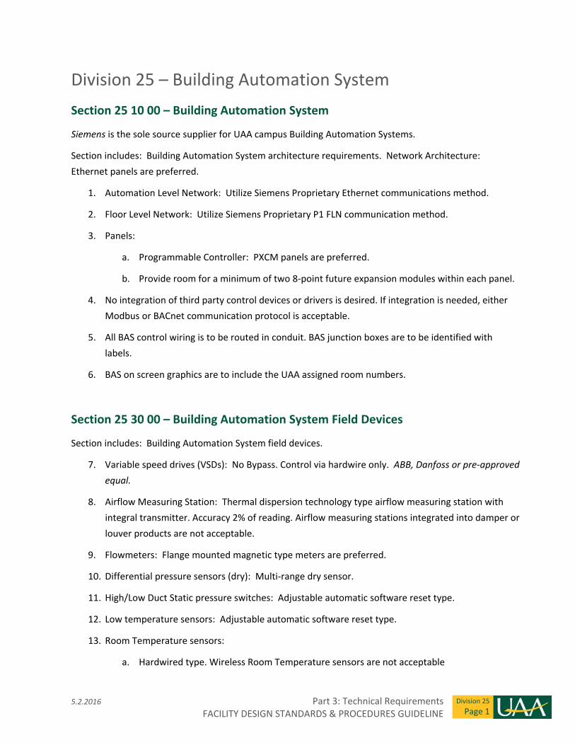
5.2.2016 Part 3: Technical Requirements FACILITY DESIGN STANDARDS & PROCEDURES GUIDELINE
Division 25
Page 1
Division 25 – Building Automation System
Section 25 10 00 – Building Automation System
Siemens is the sole source supplier for UAA campus Building Automation Systems.
Section includes: Building Automation System architecture requirements. Network Architecture:
Ethernet panels are preferred.
1. Automation Level Network: Utilize Siemens Proprietary Ethernet communications method.
2. Floor Level Network: Utilize Siemens Proprietary P1 FLN communication method.
3. Panels:
a. Programmable Controller: PXCM panels are preferred.
b. Provide room for a minimum of two 8‐point future expansion modules within each panel.
4. No integration of third party control devices or drivers is desired. If integration is needed, either
Modbus or BACnet communication protocol is acceptable.
5. All BAS control wiring is to be routed in conduit. BAS junction boxes are to be identified with
labels.
6. BAS on screen graphics are to include the UAA assigned room numbers.
Section 25 30 00 – Building Automation System Field Devices
Section includes: Building Automation System field devices.
7. Variable speed drives (VSDs): No Bypass. Control via hardwire only. ABB, Danfoss or pre‐approved
equal.
8. Airflow Measuring Station: Thermal dispersion technology type airflow measuring station with
integral transmitter. Accuracy 2% of reading. Airflow measuring stations integrated into damper or
louver products are not acceptable.
9. Flowmeters: Flange mounted magnetic type meters are preferred.
10. Differential pressure sensors (dry): Multi‐range dry sensor.
11. High/Low Duct Static pressure switches: Adjustable automatic software reset type.
12. Low temperature sensors: Adjustable automatic software reset type.
13. Room Temperature sensors:
a. Hardwired type. Wireless Room Temperature sensors are not acceptable
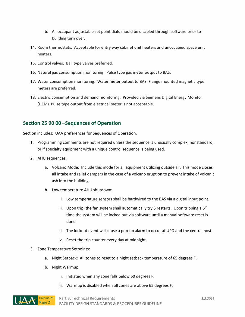
Part 3: Technical Requirements 5.2.2016 FACILITY DESIGN STANDARDS & PROCEDURES GUIDELINE
Division 25
Page 2
b. All occupant adjustable set point dials should be disabled through software prior to
building turn over.
14. Room thermostats: Acceptable for entry way cabinet unit heaters and unoccupied space unit
heaters.
15. Control valves: Ball type valves preferred.
16. Natural gas consumption monitoring: Pulse type gas meter output to BAS.
17. Water consumption monitoring: Water meter output to BAS. Flange mounted magnetic type
meters are preferred.
18. Electric consumption and demand monitoring: Provided via Siemens Digital Energy Monitor
(DEM). Pulse type output from electrical meter is not acceptable.
Section 25 90 00 –Sequences of Operation
Section includes: UAA preferences for Sequences of Operation.
1. Programming comments are not required unless the sequence is unusually complex, nonstandard,
or if specialty equipment with a unique control sequence is being used.
2. AHU sequences:
a. Volcano Mode: Include this mode for all equipment utilizing outside air. This mode closes
all intake and relief dampers in the case of a volcano eruption to prevent intake of volcanic
ash into the building.
b. Low temperature AHU shutdown:
i. Low temperature sensors shall be hardwired to the BAS via a digital input point.
ii. Upon trip, the fan system shall automatically try 5 restarts. Upon tripping a 6th
time the system will be locked out via software until a manual software reset is
done.
iii. The lockout event will cause a pop‐up alarm to occur at UPD and the central host.
iv. Reset the trip counter every day at midnight.
3. Zone Temperature Setpoints:
a. Night Setback: All zones to reset to a night setback temperature of 65 degrees F.
b. Night Warmup:
i. Initiated when any zone falls below 60 degrees F.
ii. Warmup is disabled when all zones are above 65 degrees F.
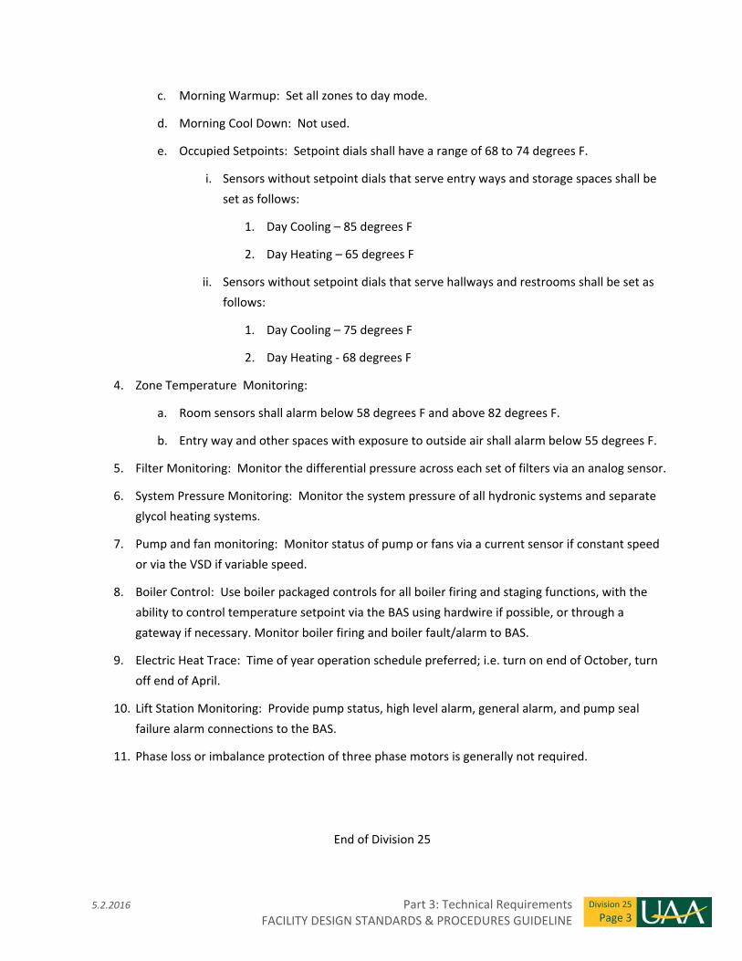
5.2.2016 Part 3: Technical Requirements FACILITY DESIGN STANDARDS & PROCEDURES GUIDELINE
Division 25
Page 3
c. Morning Warmup: Set all zones to day mode.
d. Morning Cool Down: Not used.
e. Occupied Setpoints: Setpoint dials shall have a range of 68 to 74 degrees F.
i. Sensors without setpoint dials that serve entry ways and storage spaces shall be
set as follows:
1. Day Cooling – 85 degrees F
2. Day Heating – 65 degrees F
ii. Sensors without setpoint dials that serve hallways and restrooms shall be set as
follows:
1. Day Cooling – 75 degrees F
2. Day Heating ‐ 68 degrees F
4. Zone Temperature Monitoring:
a. Room sensors shall alarm below 58 degrees F and above 82 degrees F.
b. Entry way and other spaces with exposure to outside air shall alarm below 55 degrees F.
5. Filter Monitoring: Monitor the differential pressure across each set of filters via an analog sensor.
6. System Pressure Monitoring: Monitor the system pressure of all hydronic systems and separate
glycol heating systems.
7. Pump and fan monitoring: Monitor status of pump or fans via a current sensor if constant speed
or via the VSD if variable speed.
8. Boiler Control: Use boiler packaged controls for all boiler firing and staging functions, with the
ability to control temperature setpoint via the BAS using hardwire if possible, or through a
gateway if necessary. Monitor boiler firing and boiler fault/alarm to BAS.
9. Electric Heat Trace: Time of year operation schedule preferred; i.e. turn on end of October, turn
off end of April.
10. Lift Station Monitoring: Provide pump status, high level alarm, general alarm, and pump seal
failure alarm connections to the BAS.
11. Phase loss or imbalance protection of three phase motors is generally not required.
End of Division 25

Part 3: Technical Requirements 5.2.2016 FACILITY DESIGN STANDARDS & PROCEDURES GUIDELINE
Division 25
Page 4
THIS PAGE INTENTIONALLY LEFT BLANK
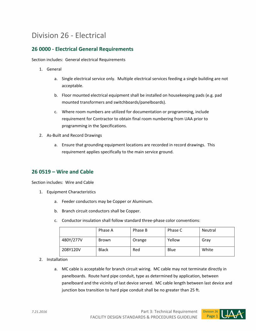
7.21.2016 Part 3: Technical Requirement FACILITY DESIGN STANDARDS & PROCEDURES GUIDELINE
Division 26
Page 1
Division 26 ‐ Electrical
26 0000 ‐ Electrical General Requirements
Section includes: General electrical Requirements
1. General
a. Single electrical service only. Multiple electrical services feeding a single building are not
acceptable.
b. Floor mounted electrical equipment shall be installed on housekeeping pads (e.g. pad
mounted transformers and switchboards/panelboards).
c. Where room numbers are utilized for documentation or programming, include
requirement for Contractor to obtain final room numbering from UAA prior to
programming in the Specifications.
2. As‐Built and Record Drawings
a. Ensure that grounding equipment locations are recorded in record drawings. This
requirement applies specifically to the main service ground.
26 0519 – Wire and Cable
Section includes: Wire and Cable
1. Equipment Characteristics
a. Feeder conductors may be Copper or Aluminum.
b. Branch circuit conductors shall be Copper.
c. Conductor insulation shall follow standard three‐phase color conventions:
Phase A Phase B Phase C Neutral
480Y/277V Brown Orange Yellow Gray
208Y120V Black Red Blue White
2. Installation
a. MC cable is acceptable for branch circuit wiring. MC cable may not terminate directly in
panelboards. Route hard pipe conduit, type as determined by application, between
panelboard and the vicinity of last device served. MC cable length between last device and
junction box transition to hard pipe conduit shall be no greater than 25 ft.
Part 3: Technical Requirement 7.21.2016 FACILITY DESIGN STANDARDS & PROCEDURES GUIDELINE
Division 26
Page 2
26 0526 – Grounding
Section includes: Grounding requirements
1. Service Grounding
a. Create an equipotential plane for the grounding system at the service entrance equipment
by connecting the service entrance ground bus to applicable grounding electrodes listed in
NEC article 250.
2. Telecommunications System Grounding and Bonding
a. Connect the telecommunications main grounding busbar (TMGB) to the service ground.
b. Connect each telecommunications grounding busbar (TGB) to building steel.
c. Bond telecommunication equipment chassis, ladder racks, cable trays, conduits,
equipment frames, cabinets, and other metallic components to a local TGB or TMGB. Each
piece of equipment shall be connected back to the local TGB or TMGB in a radial
configuration, i.e., equipment ground connections shall not be "daisy chained" and then
connected to TGB.
d. Telecom rooms shall have static dissipative flooring bonded to the TGB or TMGB in the
same room.
3. Equipment Ground
a. Include a separate equipment grounding conductor for each feeder and branch circuit.
b. Refeed existing feeders and branch circuits that do not have an existing equipment
grounding conductor.
26 0529 ‐ Hangers and Supports
Section includes: Hangers, Supports and Penetrations
1. Hangers and Supports
a. Comply with seismic design required under other divisions where applicable.
2. Wall and Floor Penetrations
a. Penetrations shall be sealed to maintain the rating of the wall or floor assembly which they
penetrate.
b. Above ceiling penetrations in full height walls shall be sealed with acoustical filler to
maintain the sound attenuating characteristics of the wall.
7.21.2016 Part 3: Technical Requirement FACILITY DESIGN STANDARDS & PROCEDURES GUIDELINE
Division 26
Page 3
c. On exterior walls and in areas where pipe leak/failure could result in water damage to
adjacent spaces, a water seal system for penetrations is required.
d. Coordinate roof penetrations with Division 7 as an integral part of the roofing system.
e. Cable tray penetrations shall be STI EZ Path Fire Rated Pathway, sized for the same cable
fill capacity as the associated cable tray.
26 0536 ‐ Cable Tray
Section includes: Cable Tray
1. Preferred Manufacturer
a. Cooper Industries B‐Line Flextray
b. Legrand Cablofil
c. Or pre‐approved equal.
2. Installation
a. Clearances
i. 12 inches above
ii. 3 inches below
iii. 6 inches to all sides
b. Provide cable tray in accessible areas only. Use conduit sleeves in inaccessible areas to
connect sections of cable tray.
c. Cable tray shall be electrically continuous and UL classified as an equipment grounding
conductor. Where cables traverse non‐continuous sections of cable tray those sections
shall be bonded together with an equipment grounding conductor.
26 0533 ‐ Raceway and Boxes for Electrical Systems
Section includes: Pull and Junction Boxes, Outlet Boxes, Conduit, Surface Mounted Raceway.
1. Surface Mounted Raceway ‐ Preferred Manufacturers
a. Wiremold
b. Hubbell
c. Or pre‐approved equal
Part 3: Technical Requirement 7.21.2016 FACILITY DESIGN STANDARDS & PROCEDURES GUIDELINE
Division 26
Page 4
2. Floor Boxes ‐ Preferred Manufacturers
a. Wiremold Evolution Series
b. Hubbell SystemOne Series
c. Or pre‐approved equal
3. Equipment Characteristics
a. Extension rings are not acceptable on new boxes.
b. Telecommunications pull boxes shall conform to BICSI standard.
c. Floor boxes covers shall be flush with finished floor except in carpeted areas where a
flange is acceptable.
d. Surface raceway shall be Wiremold 4000 or Hubbell HBL4750 or better. Pre‐wired multi‐
outlet strips are not acceptable.
e. In‐grade pull and junction boxes shall be of precast concrete construction and shall
conform to Municipality of Anchorage Standard Specifications (M.A.S.S.) division 80.
Junction box type shall be selected as required by application (Type 1A, Type 2, etc…).
f. In grade junction boxes shall have traffic rated lids.
g. Provide Liquid Tight Flexible Metal Conduit when flexible conduit is required.
4. Installation
a. Floor mounted conduit is not acceptable. This requirement applies to mechanical,
electrical and service spaces specifically.
b. Provide dedicated in grade power and telecom conduit stubouts to exterior of building for
future use. Future stubouts shall be spaced at approximately 50 ft. intervals on all exterior
sides of the building. Cap and tag stubouts with termination location (e.g., “Main Electrical
Room”).
26 0553 ‐ Electrical Identification
Section includes: Electrical Equipment Labeling
1. Equipment Labels and Nameplates
a. Rigid engraved labels and nameplates of 1/16 inch thick laminated plastic.
b. Fastened with threaded fasteners or pop rivets. Adhesive attachment not acceptable.
7.21.2016 Part 3: Technical Requirement FACILITY DESIGN STANDARDS & PROCEDURES GUIDELINE
Division 26
Page 5
2. Label and Nameplate Color
a. Normal Equipment: White letters on a black or gray background.
b. Emergency Equipment: White letters on a red background.
c. Standby Equipment: Black letters on a yellow background.
3. Label and Nameplate Text Size
a. 1 inch minimum height letters on service disconnect (red background).
b. 1/2 inch minimum height letters on secondary feeder breakers in distribution equipment,
special equipment housed in cabinets, panelboards, switchboards, motor control centers,
transformers and other electrical equipment.
c. 1/4‐inch minimum height letters on disconnects and starters for motors or fixed
appliances.
d. 1/8‐inch minimum height letters on lighting control relays, dimmer controls and remote
lighting control equipment.
e. 1/8‐inch minimum height, engraved device plates on switches and receptacles where item
controlled is not visible from the switch indicating device controlled.
f. 1/8 inch minimum height, adhesive label (black letter on clear background) indicating
branch circuit designation (panel and circuit number) on receptacle and light switch device
plates, (e.g., “PA‐30”).
4. Junction Box Marking
a. Junction boxes located in accessible shall have their cover plates marked with circuit
number or system using permanent marker.
5. Color Coding
a. Conduits and junction boxes in accessible spaces shall be color coded to identify the
system that they house. Use pre‐painted product or paint boxes and conduit prior to
installation. Color coding as follows:
i. Fire Alarm – Red
ii. Emergency – Orange
iii. Standby – Yellow
iv. BAS – Blue
6. Electrical Room
a. Provide panel locator map for each level in the electrical room door located on that level.
Part 3: Technical Requirement 7.21.2016 FACILITY DESIGN STANDARDS & PROCEDURES GUIDELINE
Division 26
Page 6
b. Provide framed building one‐line diagram in main electrical room.
7. Arc Flash
a. Provide detailed arc flash label on electrical equipment (Switchboards, Distribution Panels,
Panelboards, Transformers, etc.) in accordance with NFPA 70E. Detailed label shall include
flash boundaries, PPE levels, shock hazard level and approach boundaries.
26 0800 ‐ Commissioning of Electrical Systems
Section Includes: Recommended level of commissioning for electrical equipment and systems.
Recommended systems to commission
1. Administrative office and classroom type occupancies: Level 1 Basic Commissioning.
2. Teaching Laboratory, machine and wood shop type occupancies: Level 2 Comprehensive
Commissioning.
3. Research laboratories or occupancies containing critical applications involving life safety, health
risks or high value processing: Level 3 Critical Systems Commissioning.
Electrical equipment and systems to commission:
1. Generator and ATSs.
2. Lighting controls (including interface with other systems such as motor operated windows, A/V
equipment, etc).
3. Access control system (including door lockdown.
4. Power outage test: Proper operation of systems on generator/battery power and proper
operation on return to normal power. Systems include but are not limited to the following: phone
system, mechanical systems, fire systems, emergency lighting, BAS, elevators, etc.
5. Other systems as identified by UAA during project scoping.
26 0913 ‐ Electrical Power Monitoring
Section includes: Electrical Power Monitoring.
1. Equipment Characteristics
a. Provide power meter in main switchboard.
b. Electrical monitoring shall be compatible with the current UAA BAS standards and shall
seamlessly interface with the existing Siemens energy metering program. Pulse type
electrical metering is not acceptable.
7.21.2016 Part 3: Technical Requirement FACILITY DESIGN STANDARDS & PROCEDURES GUIDELINE
Division 26
Page 7
c. No phase loss protection/monitoring is required except by approval on a case by case
basis.
2. Installation
a. Include power monitor programming and verification in design requirements.
b. Provide BAS programming necessary to interface with the Siemens cloud based energy
metering (EMC) program.
26 0943 ‐ Lighting Controls
1. Preferred Manufacturer
a. Building lighting controls –
i. nLight/Sensorswitch
ii. Lutron
iii. Phillips
iv. Wattstopper
v. No substitutions allowed.
b. Stage lighting
i. ETC
ii. Strand
iii. Or pre‐approved equal
c. Exterior lighting
i. Lighting control panel with astronomical time clock
2. Equipment
a. Ceiling mounted occupancy sensors are preferred, even in small spaces such as offices and
storage rooms.
3. Installation
a. In spaces that are not normally occupied (e.g. Janitor closet, storage room, etc.), install
occupancy sensor/switch that requires manual operation to turn lights on and turns lights
off automatically after a preset delay when space is vacated.
b. In small office spaces, install occupancy sensor/switch that requires manual operation to
turn lights on and turns lights off automatically after a preset delay when space is vacated.
Part 3: Technical Requirement 7.21.2016 FACILITY DESIGN STANDARDS & PROCEDURES GUIDELINE
Division 26
Page 8
c. In restrooms install occupancy sensor(s). Locate such that toilet stalls are within coverage
zone. Sensor shall turn lights on automatically upon occupancy and off automatically after
a preset delay when space is vacated. Utilize dual technology type sensors.
26 2200 ‐ Low Voltage Transformers
Section includes: Secondary transformers.
1. Preferred Manufacturer
a. Square D
b. Eaton
c. Siemens
d. No substitutions allowed
2. Equipment Characteristics
a. 15 to 50kVA: 45dB
b. 51 to 150kVA: 50dB
c. 151 to 300kVA: 55dB
d. 301 to 500kVA: 60dB
3. Installation
a. Ground transformer wye secondary as a separately derived system.
b. Mount on 3 inch minimum housekeeping pad.
26 2413 – Switchboards
Section includes: Switchboards.
1. Preferred Manufacturer
a. Square D
b. Eaton
c. Siemens
d. No substitutions allowed
7.21.2016 Part 3: Technical Requirement FACILITY DESIGN STANDARDS & PROCEDURES GUIDELINE
Division 26
Page 9
2. Equipment Characteristics
a. Provide Surge Protective Device (SPD) factory installed in panelboards where required.
Remote mounted SPDs are not acceptable.
3. Installation
a. Mount switchboards on 3 inch minimum housekeeping pad with minimum 2 inch reveal on
front and sides.
b. Indicate clearances dictated by NEC Article 110 by two inches wide bright colored (red or
yellow) striping on the floor. On the floor immediately inside the striping, stencil in two
inch block letters the statement: "ELECTRICAL CLEARANCE ‐‐ STORAGE ILLEGAL INSIDE
THIS ZONE."
26 2416 – Panelboards
Section includes: Panelboards.
1. Preferred Manufacturer
a. Square D
b. Eaton
c. Siemens
d. No substitutions allowed
2. Equipment Characteristics
a. Provide Surge Protective Devices (SPDs) factory installed in panelboards where required.
Remote mounted SPDs are not acceptable.
b. Panelboards shall accept bolt on breakers only, plug in breakers are not acceptable.
3. Installation
a. Surface mount panelboards in electrical rooms.
b. Panelboards shall be located in electrical rooms when possible. Flush mounted
panelboards in corridors are acceptable.

Part 3: Technical Requirement 7.21.2016 FACILITY DESIGN STANDARDS & PROCEDURES GUIDELINE
Division 26
Page 10
26 2419 ‐ Motor Control Centers
Section includes: Motor Control Centers.
1. General
a. Do not use motor control centers. Feed motor loads from a panel dedicated to mechanical
loads. Locate motor starter/disconnect or controller as noted in section 26 2913.
26 2500 ‐ Feeder and Plug‐In Busway
Section includes: Feeder and Plug‐In Busway.
1. Preferred Manufacturer
a. Square D
b. Eaton
c. Siemens
d. No substitutions allowed
2. Equipment Characteristics
a. Busway shall be totally enclosed.
26 2616 ‐ Enclosed Contactors
Section includes: Enclosed Contactors.
1. General
a. Do not use contactors for branch circuit on/off control. Provide RIB devices for branch
circuit control instead.
b. Verify acceptable applications for contactors with UAA Facilities Maintenance and
Operations.
26 2726 ‐ Wiring Devices
Section includes: Wiring Devices.
1. Preferred Manufacturer
a. Hubbell
7.21.2016 Part 3: Technical Requirement FACILITY DESIGN STANDARDS & PROCEDURES GUIDELINE
Division 26
Page 11
b. Pass and Seymour
c. Leviton
d. No substitutions allowed
2. Device Characteristics
a. Devices shall be heavy duty commercial grade.
b. Devices shall be rated for 20 amps. Devices rated for 15 A are not acceptable.
c. Device Color:
i. White for devices fed by normal circuits
ii. Red for devices fed by optional standby or emergency circuits
d. Device plates shall be stainless steel.
e. Provide spare cover plates for floor boxes. Quantity not less than 20 percent of total floor
boxes installed.
f. Provide devices with integral USB charger in public use areas. Coordinate exact quantities
and placement with the Owner during the Design Development Phase.
3. Installation
a. Install light switches on the strike side of the door.
b. Provide light switches with pilot light in mechanical and electrical spaces.
c. Corridor receptacles shall be on a separate circuit from adjacent spaces.
d. Receptacles in corridors shall be spaced at minimum every 30 feet.
e. Provide a ceiling mounted outlet in the center of each classroom for projector.
f. Provide minimum one weatherproof receptacle on each exterior side of the building on a
dedicated circuit.
g. Provide a dedicated 50 amp twist lock receptacle in large public spaces for connection to
portable event equipment.
26 2816 ‐ Enclosed Switches and Circuit Breakers
Section includes: Enclosed Switches and Circuit Breakers.
1. Preferred Manufacturer
a. Square D
Part 3: Technical Requirement 7.21.2016 FACILITY DESIGN STANDARDS & PROCEDURES GUIDELINE
Division 26
Page 12
b. Eaton
c. Siemens
d. No substitutions allowed
2. Installation
a. Mount Main Service Disconnect on exterior of building. Shunt trip main disconnect not
acceptable.
26 2913 – Motor Starters and Controllers
Section includes: Motor Starters and Controllers.
1. Preferred Manufacturer
a. Square D
b. Eaton
c. Siemens
d. No substitutions allowed
2. Equipment Characteristics
a. Motor starters shall have adjustable solid state overload relays. Melting alloy and
bimetallic overload relays are unacceptable
b. Motor starters shall have a red LED running pilot light and Hand‐Off‐Auto switch mounted
on the enclosure.
3. Installation
a. Locate motor starters at location of equipment served when possible. Otherwise wall
mount near equipment.
26 3213 ‐ Engine Generators
Section includes: Emergency and Standby Engine Generators.
1. Preferred Manufacturer
a. Cummins Power Generation
b. Caterpillar
c. Or pre‐approved equal
7.21.2016 Part 3: Technical Requirement FACILITY DESIGN STANDARDS & PROCEDURES GUIDELINE
Division 26
Page 13
2. Equipment Characteristics
a. Generators shall be compression ignition type. Turbine or other types not acceptable.
b. Engines with special fuel requirements are not acceptable. Engine shall obtain rated
output with No. 1 or No. 2 diesel or heating fuel.
c. Mount generator on suitable full length sub‐base with seismically restrained spring‐type
vibration isolators between the sub‐base and the floor.
d. Exterior generator installations shall be housed in a heated and ventilated insulated
weatherproof walk‐in enclosure. Enclosure shall have a minimum 3 foot interior clearance
around generator for maintenance access.
e. Exterior generator housing shall be sound attenuating such that when measured at 7
meters from the set operating at full load in any direction, the sound level is less than
65dBa.
f. Provide a generator remote annunciator.
3. Installation
a. Generators shall not be installed in basements or in any location that is below grade.
b. Mount generator remote annunciator in fire department entry adjacent to fire alarm
annunciator.
c. Provide hardwired connection to the Building Automation System for annunciation
generator running status and fault status.
d. Locate generator inside of the building when possible. Where that is not possible,
coordinate location with UAA maintenance department.
26 3353 ‐ Static Uninterruptible Power Supply
Section includes: Static Uninterruptible Power Supplies.
1. Preferred Manufacturer
a. Minuteman Power Technologies
b. American Power and Conversion (APC)
c. Or pre‐approved equal
2. Equipment Characteristics
a. Coordinate equipment characteristics with UAA IT department.
Part 3: Technical Requirement 7.21.2016 FACILITY DESIGN STANDARDS & PROCEDURES GUIDELINE
Division 26
Page 14
b. Division 26 contractor to install hard wired power feed to rack mount UPSs. Rack mount
UPSs are typically OFOI equipment.
3. Installation
a. Install UPS in a readily accessible location.
b. Units with weights exceeding 50 lbs shall not be installed in ceiling areas.
26 3623 ‐ Automatic Transfer Switches
Section includes: Automatic Transfer Switches.
1. Preferred Manufacturer
a. ASCO 7000 series
b. Cummins Power Generation
c. Or pre‐approved equal
2. Equipment Characteristics
a. Switch shall be electrically operated and mechanically held.
b. Transfer switch shall have an integral control panel on the front of the switch enclosure.
3. Installation
a. Transfer switch positions shall be monitored on the remote generator annunciator panel.
26 5100 ‐ Interior Lighting
Section includes: Interior Lighting Fixtures and Lamps.
1. Equipment Characteristics
a. Fixtures shall be commercial grade.
b. LED fixtures shall be used where possible.
c. Where linear fluorescent fixtures are required, lamps shall be T8 or T5HO.
d. Fixtures using HID and incandescent lamps are not acceptable.
e. Track lighting shall be fed from a single circuit.
2. Installation
a. Provide lighting on standby circuits in public spaces when standby power is available.
7.21.2016 Part 3: Technical Requirement FACILITY DESIGN STANDARDS & PROCEDURES GUIDELINE
Division 26
Page 15
b. Light fixtures in service spaces shall be chain hung or surface mounted. Rigid pendants not
acceptable.
c. Provide night lights near switches in large spaces.
26 5200 ‐ Emergency Lighting
Section includes: Interior Lighting Fixtures and Lamps.
1. Equipment Characteristics
a. When an NEC Article 700 emergency generator is available, emergency lighting shall be
provided by fixtures that also provide normal lighting for the building and shall be supplied
from the generator via a UL924 listed device.
b. Use integral battery ballasts/inverter drivers in select fixtures when an emergency
generator is not available to achieve required emergency lighting levels.
c. Provide battery powered Emergency Lighting Units (ELUs) in mechanical and electrical
spaces. Avoid the use of ELUs in public spaces unless approved by UAA.
26 5600 ‐ Exterior Lighting
Section includes: Exterior Lighting Fixtures.
1. Equipment Characteristics
a. Exterior fixture light source shall be LED, no exceptions. Housing shall be a smooth form
factor with minimal cross sectional area. Shoebox style fixtures are not allowed.
b. Provide pedestrian scale fixtures and poles for pedestrian only areas and vehicular scale
fixtures and poles for vehicular and parking areas.
c. Exterior fixtures shall be rated to ‐40 degrees Fahrenheit.
d. Exterior fixtures, supports and pole assemblies shall be capable of withstanding 100 mph
winds with gusts to 130 mph with no damage unless more stringent requirements must be
used for a given site.
e. Provide square aluminum poles.
f. Provide pile driven or poured concrete base for pole mounted fixtures. Coordinate with
Civil to determine appropriate base type for the soil conditions.
g. Fixture and pole finish: Dark Bronze.
2. Preferred Manufacturer
Part 3: Technical Requirement 7.21.2016 FACILITY DESIGN STANDARDS & PROCEDURES GUIDELINE
Division 26
Page 16
a. Lithonia DSX Series
b. Kim Warp 9 Series
c. Or pre‐approved equal
End of Division 26
5.2.2016 Part 3: Technical Requirements FACILITY DESIGN STANDARDS & PROCEDURES GUIDELINE
Division 27
Page 1
Division 27 ‐ Communications
27 1000 ‐ Structured Cabling
Section includes: Technical requirements of the structured cabling system including extended warranty,
horizontal telecom cable, horizontal telecom cable patch panels, horizontal telecom cable outlets,
backbone fiber optic cabling, fiber optic cabling terminations, fiber optic cable patch cords, telecom racks,
telecom room flooring, and telecom room wall mounted plywood.
1. Structured cabling system warranty:
a. Provide the longer of twenty (20) years or the length of the Extended Warranty offered by
the successful manufacturer.
2. Horizontal telecom cable:
a. Category rating: Category 6A
b. Preferred cable manufacturers:
i. Commscope Systimax 360 GigaSPEED X10D 91B Series Cable (plenum or riser rated
as required)
ii. Commscope Uniprise Ultra 10G Series Cable
iii. Belden IBDN 10GX Series Cable
iv. No substitutions allowed
3. Telecom cable patch cords:
a. Category rating: Category 6A
b. Preferred cable manufacturers:
i. Commscope Systimax 360 GigaSPEED X10D 360GS10E Patch Cords
ii. Commscope Uniprise Ultra 10G Series Patch Cords
iii. Belden IBDN 10GX Series Patch Cords
iv. No substitutions allowed
c. Provide patch cords of the same manufacturer as that which provides the telecom
horizontal cabling.
Part 3: Technical Requirements 5.2.2016 FACILITY DESIGN STANDARDS & PROCEDURES GUIDELINE
Division 27
Page 2
4. Horizontal telecom cable patch panels:
a. General: Straight patch panels are preferred. Angled patch panels are not desired.
b. Preferred manufacturers:
i. Commscope Systimax GigaSPEED X10D 1100GS6 Category 6A Patch Panel
ii. Commscope Uniprise Ultra 10G Category 6A Patch Panel
iii. Belden IBDN 10GX Series Patch Panels
iv. No substitutions allowed
c. Provide patch panels of the same manufacturer as that which provides the telecom
horizontal cabling or from a manufacturer partnered with the cable manufacturer and able
to offer the structured cable system warranty.
5. Horizontal telecom outlets:
a. Preferred manufacturers:
i. Commscope Systimax GigaSPEED X10D MGS600 Information Outlet
ii. Commscope Uniprise Ultra 10G Information Outlet
iii. Belden IBDN 10GX Modular Jacks
iv. No substitutions allowed
b. Provide telecom outlets of the same manufacturer as that which provides the telecom
horizontal cabling or from a manufacturer partnered with the cable manufacturer and able
to offer the structured cable system warranty.
6. Backbone fiber optic cabling:
a. Types:
i. Indoor:
1. Multimode – 50 micron, OM3+
2. Singlemode – 8.3 micron, OS2
ii. Outdoor/Indoor:
1. Multimode – 50 micron, OM3+
5.2.2016 Part 3: Technical Requirements FACILITY DESIGN STANDARDS & PROCEDURES GUIDELINE
Division 27
Page 3
2. Singlemode – 8.3 micron, OS2
b. Preferred cable manufacturers:
i. Corning Cable Systems
1. Indoor – MIC Cable
2. Indoor/Outdoor – Freedom Cable
ii. Commscope Systimax
1. Indoor – LazrSPEED 550
2. Indoor/Outdoor ‐ LazrSPEED 550
iii. Or pre‐approved equal
7. Fiber optic connectors – Provide patch panels to house fiber optic cable connectors in the telecom
rooms.
a. Preferred connector manufacturers:
i. Corning Cable Systems
ii. Commscope Systimax
iii. Or pre‐approved equal
b. Multi‐mode
i. ST type, field terminated cam style
c. Single‐mode
i. ST type, fusion spliced, factory terminated “pigtail” connectors
8. Fiber Optic Cable Patch Cords – Fiber optic cable patch cords will be provided by UAA ITS.
9. Fiber Optic Cable Patch Panels – Provide patch panels to fully terminate fiber optic cables strands
a. Preferred connector manufacturers:
i. Corning Cable Systems CCH‐04U or CCH‐03U or CCH‐02U
ii. Commscope Systimax LazrSPEED patch/connector panels
iii. Or pre‐approved equal
Part 3: Technical Requirements 5.2.2016 FACILITY DESIGN STANDARDS & PROCEDURES GUIDELINE
Division 27
Page 4
10. Telecom racks:
a. General: Provide industry standard nineteen inch, black, two post telecom racks.
b. Preferred manufacturers
i. Chatsworth
ii. Hubbell
iii. Middle Atlantic
iv. No substitutions allowed
11. Telecom room flooring:
a. Preferred manufacturer
i. Armstrong SDT
ii. Johnsonite Granit SD
iii. Or pre‐approved equal
12. Telecom room wall mounted plywood:
a. Size: Type AC, 4 foot by 8 foot by ¾ inch.
27 4100 – Audio‐Video Communications
Section includes: Technical requirements of the audio‐video systems.
1. Cabling
a. Preferred Manufacturers
i. Belden, plenum rated
ii. West Penn, plenum rated
iii. Or pre‐approved equal
2. Racks
a. Preferred Manufacturers
i. Middle Atlantic
ii. Chatsworth
iii. Or pre‐approved equal
5.2.2016 Part 3: Technical Requirements FACILITY DESIGN STANDARDS & PROCEDURES GUIDELINE
Division 27
Page 5
b. Projectors
i. Owner Furnished
c. Switchers/Scalers
i. Extron
ii. No substitution allowed
d. Video Conferencing
i. Owner Furnished
3. Equipment Characteristics
a. Utilize 70V ceiling mounted speakers for sound distribution.
b. Include space for sliding A/V racks at lectern, credenzas and A/V closets.
c. Obtain equipment list from UAA Audio Visual Department during the Design Development
phase.
4. Installation
a. Hardwire Audio‐Video popups at conference table locations.
b. Minimum size of conduit from floor boxes to A/V racks shall be 1‐1/4”.
c. Utilize RS‐232 protocol for interface between lighting control system, electric shade
system and A/V system.
d. Provide low voltage control connection from powered projection screens to A/V
controller. In addition, provide wall mounted switch control for powered projection
screen at A/V rack location. Projection screens are specified by architectural and shall be
capable of open/close operation via a dry contact input.
End of Division 27

Part 3: Technical Requirements 5.2.2016 FACILITY DESIGN STANDARDS & PROCEDURES GUIDELINE
Division 27
Page 6
THIS PAGE INTENTIONALLY LEFT BLANK
9.6.2016 Part 3: Technical Requirement FACILITY DESIGN STANDARDS & PROCEDURES GUIDELINE
Division 28
Page 1
Division 28 – Electronic Safety and Security
28 1300 ‐ Access Control
Section includes: Access Control System (ACS) panels, ACS card readers, and ACS wiring
1. ACS panels:
a. Manufacturer
i. The Millennium Group
ii. Lenel
iii. Or pre‐approved equal
b. Panel locations:
i. Locate panels where applicable to support the building ACS design.
ii. Wall mount panels above the accessible ceiling on the secure side of applicable
doors.
2. ACS card readers:
a. Magstripe Card Reader
i. Interface: USB, RS‐232C, TTL ASCII, Wiegand, Strobe/Data
ii. Read Speed: 0.61 to 162 IPS
iii. Card Thickness: 0.007 to 0.045 inches
iv. Compatible with University Wolf card system
3. ACS wiring: As recommended by the manufacturer.
28 2310 ‐ IP Closed Circuit Television
Section includes: Video Management System software, indoor CCTV cameras, outdoor CCTV cameras,
CCTV cabling, exterior CCTV housings, Network Video Recording System (NVRS) server, and NVRS UPS.
1. Video Management System:
a. Manufacturer
i. Milestone Enterprise Edition
ii. ONSSI
iii. Or pre‐approved equal
Part 3: Technical Requirement 9.6.2016 FACILITY DESIGN STANDARDS & PROCEDURES GUIDELINE
Division 28
Page 2
2. Hardware
a. Indoor CCTV camera – Manufacturer:
i. Axis Communications 3354
ii. Sony SNCEM602RC
iii. Or pre‐approved equal
b. Outdoor CCTV camera – Manufacturer:
i. Axis Communications 3346‐VE
ii. Sony SNCEM602RC
iii. Or pre‐approved equal
c. CCTV cabling: Provided in accordance with 271000.
d. Exterior CCTV camera housing
i. Exterior, weatherproof, heated enclosure from the camera manufacturer
e. NVRS server: Windows Server based, multi core Xeon processor with 48 GB of RAM, and 1
TB of 15,000 RPM Serial Attached SCSI (SAS) drives as recommended for the number of
cameras provided on the Project (above specification to be updated with current
hardware specifications) and as recommended by the manufacturer.
f. NVRS storage: Size for a 30 day retention time of video at fifteen frames per second on
motion assuming 16 hours of motion per day.
g. NVRS network switches
i. 24 Ethernet 10/100/1000 ports with PoE and 2 X2 10 Gigabit Ethernet uplinks
h. NVRS UPS – Manufacturer:
i. APC Smart‐UPS RT Series, double conversion, 1,440 volt amps/ 1,050 watts
ii. Minuteman Endeavour Series, double conversion, ED1500RM(t)2U, 1500 volt
amps/ 1,200 watts
iii. Or pre‐approved equal
3. Camera locations:
a. Locate cameras to view incoming people at each main exit.
b. Coordinate other specific camera locations with UAA IT Services.
9.6.2016 Part 3: Technical Requirement FACILITY DESIGN STANDARDS & PROCEDURES GUIDELINE
Division 28
Page 3
28 3100 ‐ Fire Detection and Alarm
Section includes: Fire alarm system panel(s), fire alarm system addressable detectors, fire alarm system
wiring, and fire alarm system programming
4. Fire alarm system panels – Manufacturers
a. Simplex 4100ES
b. Edwards EST‐3
c. Or pre‐approved equal
5. Fire alarm system detectors
a. Multi‐sensor detector
i. Preferred detector type where automatic detection is required and detection
technology is appropriate.
b. Fixed temperature heat detector
i. Provide where automatic detection is required and environmental conditions or
required detection technology prohibit multi‐sensor detector.
c. Photoelectric smoke detector
i. Provide where automatic detection is required and environmental conditions or
required detection technology prohibit multi‐sensor detector.
d. Duct detector
i. Air sampling duct detector housing with addressable photoelectric smoke
detector.
ii. Provide remote test station in readily accessible location.
6. Fire alarm system modules
a. Monitor/Input Module
i. Converts contact closures at fans, dampers, doors, etc., to digital information for
evaluation and alarm.
b. Waterflow/Tamper Modules
i. Converts normally open waterflow contacts and supervisory tamper contacts to
digital information for evaluation and alarm.
7. Fire alarm system manual pull stations
a. Double action.
Part 3: Technical Requirement 9.6.2016 FACILITY DESIGN STANDARDS & PROCEDURES GUIDELINE
Division 28
Page 4
8. Fire alarm system notification appliances
a. Indoor horn/strobes or strobes:
i. Candela rating per NFPA 72 requirements
b. Outdoor horn/strobes
i. Candela rating per NFPA 72 requirements
ii. Operating environment from ‐31 Degrees F to 150 Degrees F
c. Sprinkler bell
i. 10” Vibrating, Diode
ii. Supply via non‐silenceable supervised notification circuit
d. Booster power supplies
i. As required for the installation
9. Fire alarm system wiring
a. Voltage drop shall not exceed 10% at the most distant device in a circuit
b. Circuits shall be sized to accommodate 20% spare capacity
10. Fire alarm system programming
a. Obtain the desired version of the system program from the University prior to
programming.
b. Provide reporting functionality of alarm or trouble condition back to the monitoring
system.
End of Division 28
5.2.2016 Part 3: Technical Requirements FACILITY DESIGN STANDARDS & PROCEDURES GUIDELINE
Division 31
Page 1
Division 31 – Earthwork
Section 31 10 00 – Site Clearing
Section includes: Erosion and sedimentation control, selective site demolition, and site clearing.
Part 1 – Design Requirements
1. Site clearing shall be minimized to the extent possible.
a. Tree removal shall include
i. Tree removal (above ground)
ii. Stump removal (below ground)
2. Clearing and grubbing :
a. General: Remove trees, shrubs, grass and other vegetation, improvements, or
obstructions as required to permit installation of new construction.
i. Completely remove stumps, roots, and other debris protruding through ground
surface.
ii. Use only hand methods for grubbing inside drip line of trees indicated to remain.
3. Site Salvage:
a. All demolished material shall be offered to the Owner. If not desired by the Owner,
materials shall become property to be removed from site and disposed of by the
Contractor at his expense unless noted otherwise on the Drawings.
Part 2 – Products
1. All products are per MASS.
Part 3 – Execution
1. All products are installed per MASS.
Section 31 15 00 – Earth Moving
Section includes: Work necessary to shape the existing ground in order to install proposed designs
Section per MASS
Section 31 20 00 – Plant Protection and Salvaging
Section includes: Protecting of existing vegetation that is affected by execution of the Work, whether
temporary or permanent construction and collection of materials for reuse.
Part 1 – Design Requirements
1. Engage a qualified Arborist to direct plant‐protection measures in the vicinity of trees, shrubs, and
other vegetation indicated to remain.
Part 3: Technical Requirements 5.2.2016 FACILITY DESIGN STANDARDS & PROCEDURES GUIDELINE
Division 31
Page 2
2. Engage a qualified Arborist to direct plant salvage work for trees, shrubs, and other vegetation
indicated to be salvaged.
3. No earthwork or grading shall be done within the drip line or identified protection boundary of
existing trees that are to be protected and remain.
4. Protection fence shall be installed around the entire boundary of vegetation to be protected.
5. Protection fence shall be 6’ chain link fence.
Part 2 – Products
1. All products are per MASS.
Part 3 – Execution
1. All products are installed per MASS.
End of Division 31
7.21.2016 Part 3: Technical Requirements FACILITY DESIGN STANDARDS & PROCEDURES GUIDELINE
Division 32
Page 1
Division 32 – Exterior Improvements
Section 32 90 00 – Planting General
Section includes: Planting Submittals and inspection requirements
Part 1 – Design Requirements
Per individual Division 32 sections.
Part 2 – Products
Per individual Division 32 sections.
Part 3 – Execution
The consultant should follow this general process as a timeline for installations and inspections of Division
32 products and materials, or develop a new one as approved by UAA. These processes will supercede
similar components of MASS.
1. Submittals
a. Contractor shall submit the following to the Design Project Manager prior to beginning
installation:
i. Qualification data for:
1. Landscape Contractor
2. Landscape Construction Supervisor
3. Arborist
4. Planting Soil Manufacturer
5. Proof of Alaska certification for handling of pesticides/herbicides
ii. Product data – for each specified product
iii. Associated product certifications
1. Seed
2. Limestone and Fertilizer
3. Manufacturer’s certified analysis of standard products
iv. Product sources
1. The Contractor shall notify the Design Project Manager of the source of
the planting soil.
Part 3: Technical Requirements 7.21.2016 FACILITY DESIGN STANDARDS & PROCEDURES GUIDELINE
Division 32
Page 2
2. Plant Materials: Include quantities, sizes, quality, and sources for plant
materials.
3. Boulders: Include source location for boulders, and representative photos
typical of rock yard or quarry specific to the Project.
v. Product testing
1. For each unamended soil type and the specified planting soil, furnish soil
analysis and a written report by a qualified soil‐testing laboratory. At a
minimum, soil analysis shall include:
a. Percentages of organic matter.
b. Gradation of sand, silt, and clay content (including a grain size
distribution curve)
c. Cation exchange capacity.
d. Percentage of deleterious material (greater than #4 screen).
e. pH.
f. Mineral and plant‐nutrient content of soil (nitrogen, phosphorous
and potassium at a minimum).
vi. Samples ‐ for each specified product
vii. Maintenance Plan
2. Exterior Plants
a. Inspection – Contractor shall receive approval of exterior plant products and materials
prior to offloading of material. Attendance required by:
i. Landscape Architect
ii. UAA Operations Representative
iii. Contractor Representative
b. Inspection – Contractor shall receive approval of planting bed layout and installation prior
to moving ahead with next product and/or material installation. Attendance required by:
i. Landscape Architect
ii. UAA Operations Representative
iii. Contractor Representative
3. Subgrade and Drainage
7.21.2016 Part 3: Technical Requirements FACILITY DESIGN STANDARDS & PROCEDURES GUIDELINE
Division 32
Page 3
a. Inspection – Contractor shall receive approval of subgrade and drainage prior to moving
ahead with next product and/or material installation. Attendance required by:
i. Landscape Architect
ii. UAA Operations Representative
iii. Contractor Representative
4. Planting soil
a. Planting soil Installation Inspection – Contractor shall receive approval of planting soil
placement prior to moving ahead with installation of plant materials. Attendance required
by:
i. Landscape Architect
ii. UAA Operations Representative
iii. Contractor Representative
5. Substantial Completion – All products and materials complete prior to this inspection
a. Inspection – Contractor shall receive punch list of final items to complete before project
closeout. Attendance required by:
i. Landscape Architect
ii. UAA Project Manager
iii. UAA Operations Representative
iv. Design Team Prime Project Manager
v. Contractor Representative
6. Irrigation
a. Inspection – Perform system test, per 32 98 00 Irrigation. Attendance required by:
i. Landscape Architect
ii. UAA Operations Representative
iii. Contractor Representative
7. Acceptance Inspection
a. Inspection to verify that all products and materials have been installed per Substantial
Completion punch list.
b. Attendance required by:
i. Landscape Architect
Part 3: Technical Requirements 7.21.2016 FACILITY DESIGN STANDARDS & PROCEDURES GUIDELINE
Division 32
Page 4
ii. UAA Operations Representative
iii. Design Team Prime Project Manager
iv. Contractor Representative
8. Warranty Completion Inspection
a. Attendance required by:
i. Landscape Architect
ii. UAA Operations Representative
iii. Design Team Prime Project Manager
iv. Contractor Representative
Section 32 91 00 – Planting soil
Section includes: Planting soil.
Part 1 – Design Requirements
Part 2 – Products
1. All products are per MASS, with additions listed below.
2. Submittal – Contractor to provide submittal to UAA that indicates proposed location for planting
soil location, with either test results that prove the soil does not include weed species or a UAA rep
can visit the pit location and verify in person. This submittal is necessary to move ahead with
planting soil installation.
Part 3 ‐ Execution
1. All products are installed per MASS.
Section 32 92 00 – Lawns and Grasses
Section includes: Seed Mixes, Lawn Fertilizer, Lawn Lime, Tackifier (mulch), Sod
Part 1 – Design Requirements
1. Aesthetics.
2. Safety.
3. Plant health and longevity.
Part 2 – Products
7.21.2016 Part 3: Technical Requirements FACILITY DESIGN STANDARDS & PROCEDURES GUIDELINE
Division 32
Page 5
1. All products are per MASS.
Part 3 ‐ Execution
1. All products are installed per MASS.
Section 32 93 00 – Exterior Plants
Section includes: Plant Material, Mulch, Anti‐desiccants, Fertilizer/Lime, Water, Wood Stakes and Ties,
Herbicides, Landscape Edging, Pesticides/Herbicides
Part 1 – Design Requirements
1. Aesthetics.
2. Safety.
3. Plant health and longevity.
Part 2 ‐ Products
1. All products are per MASS, with additions listed below.
2. All plant materials shall be nursery grown. No native dug material shall be allowed unless for use
within revegetation or naturalized planting areas.
3. Plant Materials NOT approved for use on UAA Campus:
a. All species on the following lists:
i. USDA Select Invasive Plants of Alaska (latest version)
ii. In addition to those deemed invasive by USDA per above, trees, shrubs, and
perennials that shall not be used without UAA approval:
1. Prunus padus – Mayday
2. Caragana arborescens – Peashrub
2. Landscape Edging:
a. General: heavy‐duty commercial grade aluminum landscape edging
b. Model: 3/16” thickness by 5.5” depth edging. Edging profile shall allow overlapped/locked
connections via telescoping together utilizing channels along top and bottom edges.
c. Attachment: Staked with minimum 12” depth stakes.
d. Finish: Aluminum
3. Shovel‐cut edge shall be:
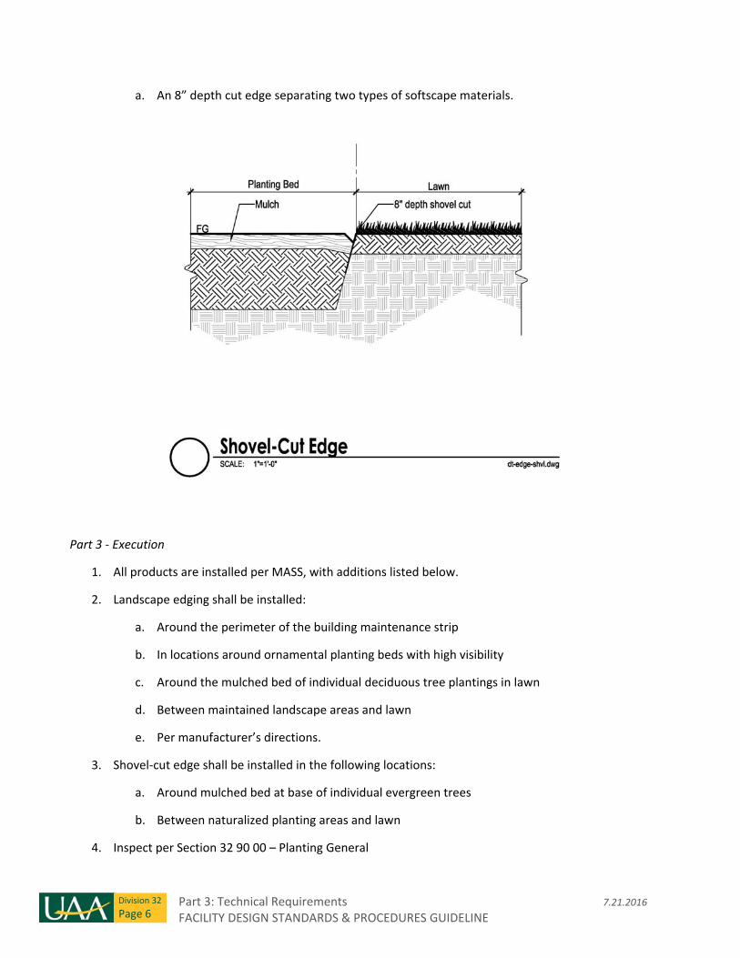
Part 3: Technical Requirements 7.21.2016 FACILITY DESIGN STANDARDS & PROCEDURES GUIDELINE
Division 32
Page 6
a. An 8” depth cut edge separating two types of softscape materials.
Part 3 ‐ Execution
1. All products are installed per MASS, with additions listed below.
2. Landscape edging shall be installed:
a. Around the perimeter of the building maintenance strip
b. In locations around ornamental planting beds with high visibility
c. Around the mulched bed of individual deciduous tree plantings in lawn
d. Between maintained landscape areas and lawn
e. Per manufacturer’s directions.
3. Shovel‐cut edge shall be installed in the following locations:
a. Around mulched bed at base of individual evergreen trees
b. Between naturalized planting areas and lawn
4. Inspect per Section 32 90 00 – Planting General
7.21.2016 Part 3: Technical Requirements FACILITY DESIGN STANDARDS & PROCEDURES GUIDELINE
Division 32
Page 7
Section 32 94 00 – Landscape Accessories
Section includes: Boulders, landscape fabric, geotextile fabric, mineral mulch and building maintenance
strip.
Part 1 – Design Requirements
Part 2 ‐ Products
1. All products are per MASS, with additions noted below.
2. Building maintenance strip
a. Preferred product:
i. Mulch: Mineral mulch with type per project.
ii. Landscape edging: per 32 93 00
iii. Landscape fabric: per MASS
b. Alternative selection:
i. Mulch: Shredded bark mulch, per MASS
Part 3 ‐ Execution
1. All products are installed per MASS, or per manufacturer’s recommendation, with additions noted
below.
Section 32 97 00 – Landscape Maintenance
This Section includes: Maintenance Period and Warranty, Maintenance of Exterior Plants, Maintenance of
Lawns and Grasses, Clean‐up, Inspection
1. Maintenance Period and Warranty shall be:
a. For exterior plants and everything included in this section: one year
b. For lawns and grasses and everything included in this section: one year
2. Inspection to occur after warranty period ends – see 32 90 00 – Planting General.
Section 32 98 00 – Irrigation
Section includes: All work and materials for the design and installation of the various types of irrigation
systems.
Part 3: Technical Requirements 7.21.2016 FACILITY DESIGN STANDARDS & PROCEDURES GUIDELINE
Division 32
Page 8
Part 1 – Design Requirements
Part 2 – Products
1. Watering Bags
a. For single stem trees with branching above 25”.
i. General: Upright style watering bag. Provide single back with minimum 15 gallon
storage for up to 4” caliper. Provide two bags or minimum 25 gallon storage for
greater than 4” caliper.
ii. Material: green polyethylene with nylon webbing, polypro straps and nylon
zippers. UV stabilized to withstand exposure to sunlight. Fill opening to fit up to 3"
diameter hose
iii. Notes: Bag should be designed to release water within 5 to 9 hours after filling.
During maintenance period, bag should be refilled sufficient to maintain adequate
soil moisture.
b. For multi‐stem trees or those with branching below 25”.
i. General: Low profile donut‐style watering bag with minimum 15 gallon capacity.
ii. Material: PVC with Removable dual PVC emitters. Continuously waters for 5 to 8
hours.
iii. Notes: Bag should be designed to release water within 5 to 9 hours after filling.
During maintenance period, bag should be refilled sufficient to maintain adequate
soil moisture.
2. Irrigation system:
a. General:
i. All irrigation system components shall be new and of industrial or commercial
grade. All components shall be fabricated by brand name manufacturers.
ii. Trees and shrub shall be irrigated by dripline emitter tubing or individual drip
emitters. Perennials hall be irrigation by dripline emitter tubing, individual droip
emitters or bubblers. Areas of turf shall be irrigated by pop‐up sprinklers.
iii. Irrigation main and lateral lines that go below hardscape shall be sleeved.
b. HDPE Pipes and fittings: Pipe and fittings for use in irrigation main piping 1‐1/2 inches in
diameter or less shall be SDR‐11 High Density Polyethylene pipe (HDPE). Piping over 1‐1/2
inches in diameter shall be SDR‐17 High Density Polyethylene pipe (HDPE).
7.21.2016 Part 3: Technical Requirements FACILITY DESIGN STANDARDS & PROCEDURES GUIDELINE
Division 32
Page 9
c. Trace Wire ‐ For irrigation lines where control wiring is not run with the line, 12‐gauge
copper trace wire shall be installed as shown on drawings.
d. Control Wiring and Automatic Controllers:
i. Control wire shall be UF‐UL listed, color coded copper conductor direct burial size
18. Where control wire runs are anticipated to be greater than 800 feet, provide
14 gauge wiring. Do not use green color coded wire.
1. Provide waterproof Wire Connectors for wiring.
ii. Automatic Controller:
1. Controllers shall be programmable and shall operate on 120 VAC input,
with 24 VAC output to electrical valves.
e. Control Valves and Valves:
i. Install valves in valve boxes.
f. Valve box with lid:
i. Plastic valve box suitable for designed irrigation system with lockable lid. Submit
for approval.
g. Quick Coupler:
i. Quick couplers shall include valve keys for ¾” hose connection inclusive of valve
for turning water on and off prior to the hose connection.
ii. Pipe design for water connection to quick couplers shall be sufficient to provide a
minimum of 45psi and 30gpm at the quick coupler.
Part 3 – Execution
1. Install per manufacturer’s instructions.
2. Perform System Test / Inspection:
a. A pressure and leakage test will be conducted in the presence of the Design Project
Manager following the completion of the main and lateral line assembly. The irrigation
lines shall be tested under hydrostatic pressure to 60 psi. The test duration shall be 2
hours. Test pressure shall be maintained for the duration of the test. If leaks develop, the
joints shall be replaced and the test repeated until the entire system is proven watertight.
Tests shall be observed and approved by the Design Project Manager prior to completion
of backfill.

Part 3: Technical Requirements 7.21.2016 FACILITY DESIGN STANDARDS & PROCEDURES GUIDELINE
Division 32
Page 10
End of Division 32

END OF DOCUMENT