Embed Size (px)
Citation preview
IEE Transactions on Power Apparatus and Systems, Vol. PAS-95, no. 4, JulyIAugust 1976
STANDBY AND EMERGENCY POWER SUPPLY OF GERMAN NUCLEAR POWER PLANTS Alexander Borst
Kraftwerk Union AG Erlangen, West Germany
ABSTRACT
In ensuring nuclear safety by the utmost reliable supply of power to all safety related systems under all emergency conditions, U.S. power plants rely heavily on redundant offsite power sources. For years German plant designers have been and are still placing a greater emphasis on onsite power sources in the form of highly redundant sophisticated Diesel generating sets. This difference in fundamental design philosophy and the concepts underlying the Diesel power systems incorporated into German nuclear stations are diSCUSSed.
INTRODUCTION
It has long been realized in Germany that it is either impossible or economically not feasible at most locations, where large nuclear power plants would be permitted in the country, to provide two adequate power line connections from truly independent electrical systems. Two incoming feeders from a common grid, especially if they are at the same voltage level and coupled at the station bus, are considered prone to simultaneous failures even if they are physically segregated from one another. They are equally vulnerable to electrical system faults and all external disturbances, especially lightning, storms and earthquakes.
Historically, Diesel generators have wide usage in Germany wherever emergency power is required, e.g. hospitals, airports, large office buildings, department stores, etc. Consequently, many highly reliable designs have matured over the years. Diesel standby power systems can be provided and maintained in nuclear power plants with almost any degee of operating availability that is required and usu- ally at far less cost than duplicate transmission circuits. They can be designed to render them impervious to the many external distur- bances that can jeopardize transmission lines, to suit the emergency cooling requirements of any type of reactor and to provide the de- sired operating redundancy.
In recognition of the fact that a reliable second offsite source of ample power which is adequately independent of the main power system, both physically and electrically, is not always available, the German standards’ also allow the concept of installing circuit break- ers at the generator terminals. Regardless of whether the combina- tion of low-voltage generator breakers and only one external feeder or no low-voltage generator breakers and two external feeders is selected, the Diesel power system must be designed in the same way as an independent and reliable standby power supply with a redun- dancy supplementing that of the multi-train reactor emergency cool- ing system.
Paper C 75 1284, recommended and approved by the IEEE Power Generation Cormnittee of the IEEE Power Engjneering Society for presentation at the IEEE PES Winter Meeting, New York, N.Y., January 26-31, 1975. This paper was u p graded to transactions status, PC 75 652-8, for presentation by title for written dis- cussion at the IEEE 1975 Joint Power Generation Conference. Manuscript sub- mitted September 23,1974;made available for printing July 28,1975.
1080
COMPARISON OF POWER CIRCUITRY IN U.S. AND GERMAN NUCLEAR STATIONS
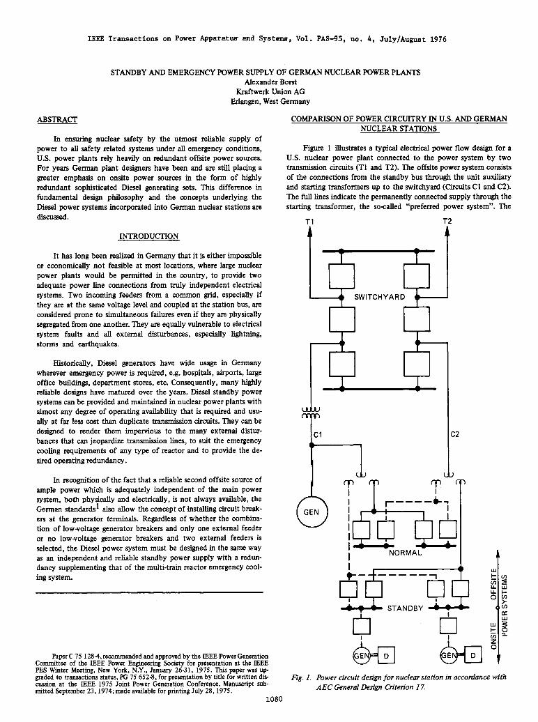
Figure 1 illustrates a typical electrical power flow design for a U.S. nuclear power plant connected to the power system by two transmission circuits (T1 and T2). The offsite power system consists of the connections from the standby bus through the unit auxiliary and starting transformers up to the switchyard (Circuits C1 and C2). The full lines indicate the permanently connected supply through the starting transformer, the so-called “preferred power system”. The
T1 T2
t t 1 SWITCHYARD
51 I I
tl I C2
I ’ A - I NORMAL 1
STANDBY
w t
Eg. 1. Power circuit design for nuclear station in accordance with AEC General Design Criterion 17.
unit auxiliary transformer provides an alternate source of power supply via the broken lines to the standby bus, to which the Diesel generators are also connected.2
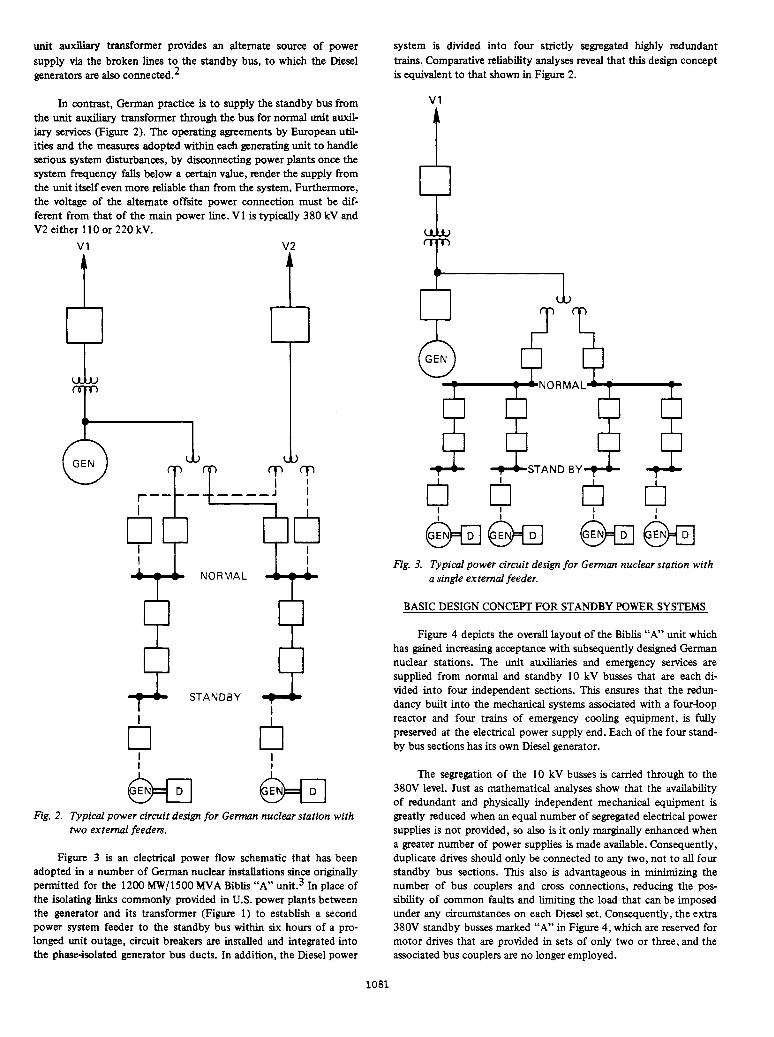
In contrast, German practice is to supply the standby bus from the unit auxiliary transformer through the bus for normal unit auxil- iary services (Figure 2). The operating agreements by European util- ities and the measures adopted within each generating unit to handle serious system disturbances, by disconnecting power plants once the system frequency falls below a certain value, render the supply from the unit itself even more reliable than from the system. Furthermore, the voltage of the alternate offsite power connection must be dif- ferent from that of the main power line. V1 is typically 380 kV and V2 either 110 or 220 kV.
v1 v2
I uhu
T
T T T T I t !---I--* I
I
9 9
4 STANDBY 6
I
0 I
I
0 I
Fig. 2. Typical power circuit design for German nuclear station with two external feedem
Figure 3 is an electrical power flow schematic that has been adopted in a number of German nuclear installations since originally permitted for the 1200 MW/l500 MVA Bibb “A” unit.3 In place of the isolating links commonly provided in U.S. power plants between the generator and its transformer (Figure 1) to establish a second power system feeder to the standby bus within six hours of a pro- longed unit outage, circuit breakers are installed and integrated into the phaseisolated generator bus ducts. In addition, the Diesel power
system is divided into four strictly segregated highly redundant trains. Comparative reliability analyses reveal that this design concept is equivalent to that shown in Figure 2.
v1
U L J
T
+ +STAND BY+ +
Fig. 3. Dpical power circuit design for German nuclear station with a single external feeder.
BASIC DESIGN CONCEPT FOR STANDBY POWER SYSTEMS
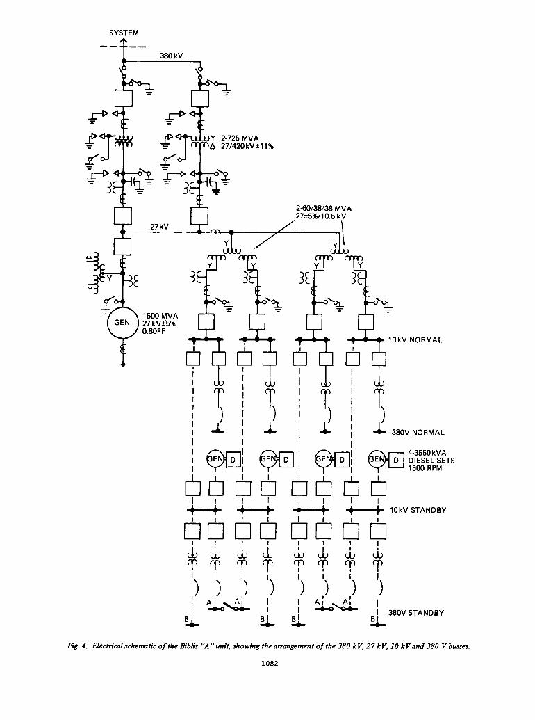
Figure 4 depicts the overall layout of the Biblis “A” unit which has gained increasing acceptance with subsequently designed German nuclear stations. The unit auxiliaries and emergency services are supplied from normal and standby 10 kV busses that are each di- vided into four independent sections. This ensures that the redun- dancy built into the mechanical systems associated with a four-loop reactor and four trains of emergency cooling equipment, is fully preserved at the electrical power supply end. Each of the four stand- by bus sections has its own Diesel generator.
The segregation of the 10 kV busses is carried through to the 380V level. Just as mathematical analyses show that the availability of redundant and physically independent mechanical equipment is greatly reduced when an equal number of segregated electrical power supplies is not provided, so also is it only marginally enhanced when a greater number of power supplies is made available. Consequently, duplicate drives should only be connected to any two, not to all four standby bus sections. This also is advantageous in minimizing the number of bus couplers and cross connections, reducing the pos- sibility of common faults and limiting the load that can be imposed under any circumstances on each Diesel set. Consequently, the extra 380V standby busses marked “A” in Figure 4, which are reserved for motor drives that are provided in sets of only two or three, and the associated bus couplers are no longer employed.
1081
SYSTEM --
Y 2-725 MVA A 27/420kV+ll%
2-60138138 MVA 27?5%/10.5 kV
10kV NORMAL
38OV NORMAL
Rg. 4. Electridschematic of the Bibb “A”unit, showing the arrangement of the 380 kV, 27 kV, I O kVand 380 V busses.
1082
Design of Diesel Engines
As unit capability rises and safety requirements are increased, the standby power needed also becomes greater. Dividing the emer- gency cooling and aftercooling services into separate trains, possesses the advantages of reducing the ratin@ of the individual motor drives and of limiting the standby power requirements. Each of the four 5WAuty reactor cooling trains associated with a 1300 MWe FWR unit like those in the Biblis nuclear station, constitutes a load that can be met by a high-speed ldcylinder Diesel engine with a con- tinuous rating of about 3,000 kW. Some European manufacturers have worked hard at extending this capability range and are now able to offer 20cylinder engines rated up to 3,600 kW.
The large induction motors rated more than 5 0 0 kW driving the pumps associated with the emergency cooling and aftercooling sys- tems, have to be started and must overcome an approx. 200% pull- out torque. High-speed turbocharged Diesel engines are preferred due to their favorable power/weight ratio, excellent regulation character- istics and short loading times. However, they possess a relatively small flywheel mass (Wr2) and only develop about half their rated power at the moment of initial loading. An obvious fmt step in solving this problem is to divide the total load into several groups of motors that are switched onto the standby bus in sequence.
Whether flywheels should be added to the Diesel engines so as to flatten their inherently drooping loadlspeed characteristics, is less obvious. Experience shows increasingly clearer that the criteria of a practically constant frequency in the standby power system should not be applied to the Diesel engines. By allowing dropping load/ speed characteristics, it is usually possible to dispense with flywheels which slow down the acceleration and the loading times of the Diesel sets. Loads requiring constant frequency, e.g. instrumentation and controls, are supplied in nuclear stations not from such Diesel sources, but from precisely regulated inverters.
Design of Diesel Generators and Motor Starters
The ratings of Diesel generators in nuclear power plants gener- ally lie in the range of 2 to 4 MVA at either 6 or 10 kV. The robust design of these highly conventional machines allows them to with- stand the severe stresses of starting large induction motors.
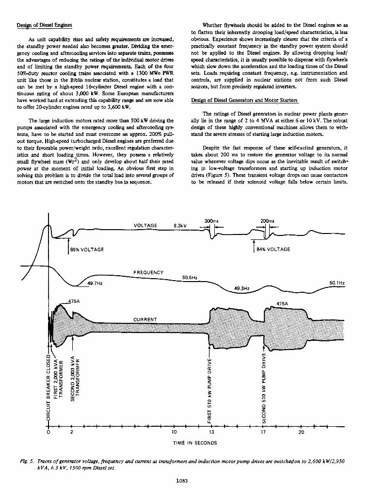
Despite the fast response of these self-excited generators, it takes about 200 ms to restore the generator voltage to its normal value whenever voltage dips occur as the inevitable result of switch- ing in low-voltage transformers and starting up induction motor drives (Figure 5 ) . These transient voltage drops can cause contactors to be released if their solenoid voltage falls below certain limits.
VOLTAGE 6.3kV 3 m s
85% VOLTAGE
Fig. 5. Traces of genemtor voltage, frequency and current as tmnrformers and induction motor pump drives are switchedon to 2,600 kWj2.950 kVA, 6.3 kV, 1500 rpm Diesel set.
1083
Attention must also be paid to the fact that the torque of running motors decreases as the square of the voltage. Consequently, the effect of such transient reductions in voltage on the motor drives and their controls must be carefully considered.
The European system interconnection authority recommends specifying that power plant motor drives operate stably down to 70% rated voltage since a 30% voltage drop is considered to be the abso- lute maximum that can occur. German standards4 for Diesel power systems in nuclear stations stipulate the design criterion of a maxi- mum voltage drop of 25% at the loads. After initial difficulties, manufacturers succeeded in fulfilling the requirement of supplying contactors with specially designed solenoids to ensure that release is only possible when the energizing voltage drops below 70% of the nominal value.
Another solution to this problem is to energize the contactors from either a dc or safe ac bus. This has the indisputable advantage of holding the contactors closed regardless of variations in the main ac voltage. However, connecting the contactor solenoids to the main ac voltage within the individual motor feeders allows the following even more important advantages to be gained:
- the failure of a control circuit only affects the associated feeder,
- no lengthly control wiring between feeders with associated potential failure possibility and excessive voltage drops, and
- simple complete disconnection of voltage within any feeder.
Generator kVA ratings must be sufficiently large to e n m that the greatest loading of the preloaded generators that can occur when transformers or motors are switched in, does not result in transient voltage dips in excess of 25%. This is the essential prerequisite to maintaining the highly reliable practice of tapping the main ac within each motor feeder to obtain a control voltage that is independent of any other feeders.
Design of Diesel Peripheral Equipment
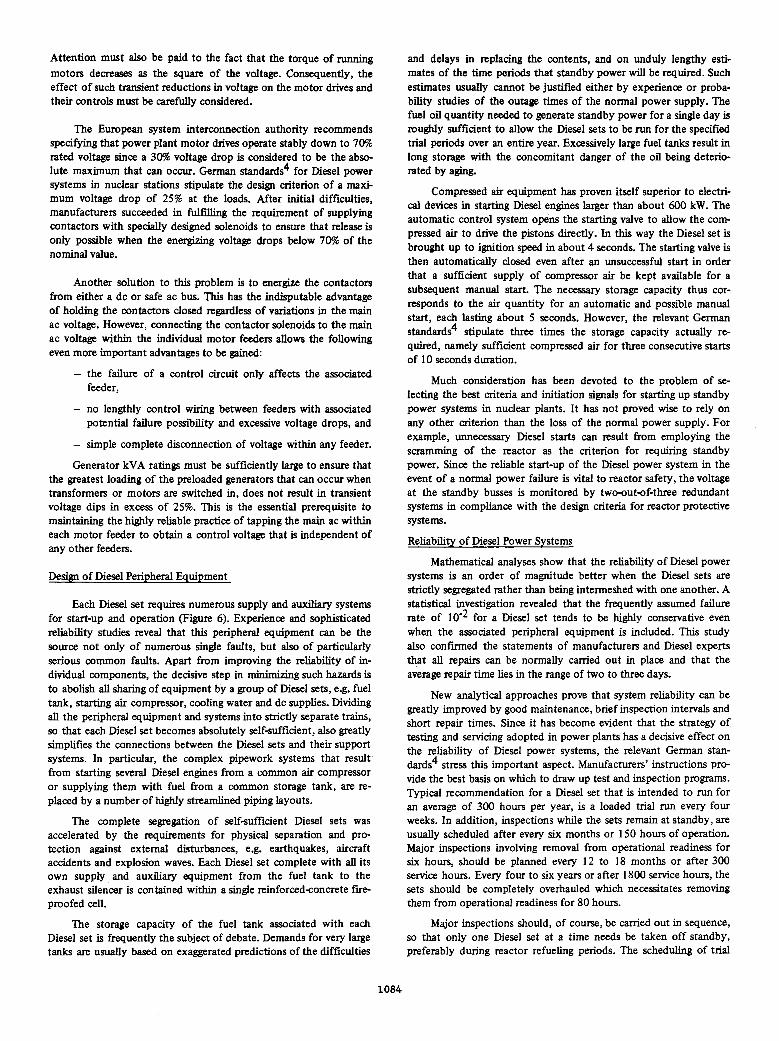
Each Diesel set requires numerous supply and auxiliary systems for start-up and operation (Figure 6) . Experience and sophisticated reliability studies reveal that this peripheral equipment can be the source not only of numerous single faults, but also of particularly serious common faults. Apart from improving the reliability of in- dividual components, the decisive step in minimizing such hazards is to abolish all sharing of equipment by a group of Diesel sets, e.g. fuel tank, starting air compressor, cooling water and dc supplies. Dividing all the peripheral equipment and systems into strictly separate trains, so that each Diesel set becomes absolutely self-sufficient, also greatly simplifies the connections between the Diesel sets and their support systems. In particular, the complex pipework systems that result from starting several Diesel engines from a common air compressor or supplying them with fuel from a common storage tank, are re- placed by a number of highly streamlined piping layouts.
The complete segregation of self-sufficient Diesel sets was accelerated by the requirements for physical separation and pro- tection against external disturbances, e.g. earthquakes, aircraft accidents and explosion waves. Each Diesel set complete with all its own supply and auxiliary equipment from the fuel tank to the exhaust silencer is contained within a single reinforcedsoncrete fue- proofed cell.
The storage capacity of the fuel tank associated with each Diesel set is frequently the subject of debate. Demands for very large tanks are usually based on exaggerated predictions of the difficulties
and delays in replacing the contents, and on unduly lengthy esti- mates of the time periods that standby power will be required. Such estimates usually cannot be justified either by experience or proba- bility studies of the outage times of the normal power supply. The fuel oil quantity needed to generate standby power for a single day is roughly sufficient to allow the Diesel sets to be run for the specified trial periods over an entire year. Excessively large fuel tanks result in long storage with the concomitant danger of the oil being deterie rated by aging.
Compressed air equipment has proven itself superior to electri- cal devices in starting Diesel engines larger than about 600 kW. The automatic control system opens the starting valve to allow the com- pressed air to drive the pistons directly. In this way the Diesel set is brought up to ignition speed in about 4 seconds. The starting valve is then automatically closed even after an unsuccessful s t a r t in order that a sufficient supply of compressor air be kept available for a subsequent manual start. The necessary storage capacity thus cor- responds to the air quantity for an automatic and possible manual start, each lasting about 5 seconds. However, the relevant German standards4 stipulate three times the storage capacity actually re- quired, namely sufficient compressed air for three consecutive starts of 10 seconds duration.
Much consideration has been devoted to the problem of se- lecting the best criteria and initiation signals for starting up standby power systems in nuclear plants. It has not proved wise to rely on any other criterion than the loss of the normal power supply. For example, unnecessary Diesel starts can result from employing the scramming of the reactor as the criterion for requiring standby power. Since the reliable start-up of the Diesel power system in the event of a normal power failure is vital to reactor safety, the voltage at the standby busses is monitored by two-outaf-three redundant systems in compliance with the design criteria for reactor protective systems.
Reliability of Diesel Power Systems
Mathematical analyses show that the reliability of Diesel power systems is an order of magnitude better when the Diesel sets are strictly segregated rather than being intermeshed with one another. A statistical investigation revealed that the frequently assumed failure rate of for a Diesel set tends to be highly conservative even when the associated peripheral equipment is included. This study also confmed the statements of manufacturers and Diesel experts that all repairs can be normally carried out in place and that the average repair time lies in the range of two to three days.
New analytical approaches prove that system reliability can be greatly improved by good maintenance, brief inspection intervals and short repair times. Since it has become evident that the strategy of testing and servicing adopted in power plants has a decisive effect on the reliability of Diesel power systems, the relevant German stan- d a r d ~ ~ stress t h i s important aspect. Manufacturers’ instructions pro- vide the best basis on which to draw up test and inspection programs. Typical recommendation for a Diesel set that is intended to run for an average of 300 hours per year, is a loaded trial run every four weeks. In addition, inspections while the sets remain at standby, are usually scheduled after every six months or 150 hours of operation. Major inspections involving removal from operational readiness for six hours, should be planned every 12 to 18 months or after 300 service hours. Every four to six years or after 1800 service hours, the sets should be completely overhauled which necessitates removing them from operational readiness for 80 hours.
Major inspections should, of course, be carried out in sequence, so that only one Diesel set at a time needs be taken off standby, preferably during reactor refueling periods. The scheduling of trial
1084
ALARMS OPERATION CONTROL TONORMAL BUS OF LOADS BREAKERS CONTROL CONTROL PREPARATION PRoTECTloN START TRIAL SHUT-DOWN RECONNECTION SWITCHING CIRCUIT EXCITATION START.UP
I , AUTOMATIC SEQUENTIAL OPERATION I I I (
( I I
-1 WATER j I I CONTROL VOLTAGE
COMBUSTION AIR
L I t E I I I
I I I I I
sv
%'=STARTING VALVE I I I I I I I I I I I
C=COOLER FOR WATER, SUPERCHARGING AIR, AND OIL.
I
I I I I DIESEL ENGINE I I
PH=PREHEATING
PL=PRELUBRICATION
SC=SUPERCHARGER
I 3 1 NORMAL BUS
I STANDBY SWITCHGEAR
I I 1 , I
I' L-J---J I---- t I I 1' 1' I' I'
LOADS ARRANGED IN GROUPS FOR SEQUENTIAL SWITCHING PURPOSES
Fig. 6. Necessary supply and auxiliary systems for a standby Diesel set.
runs and minor inspections is also important in ensuring maximum reliability. A trial run entails operating a Diesel set at not less than half load for about two hours. This requires that it be run in parallel with the normal power supply. Since the probability exists that a fault in the unit auxiliary seMces could trip the Diesel generator, not more than one Diesel set may be run on trial at any one time. Rather than test all the Diesel generators in sequence on the same day, the reliability of the Diesel power system can be appreciably improved if the trial runs be staggered evenly over the test interval of four weeks. Thus, for example, if a four-set Diesel power system is required in an emergency situation, only one of the Diesel sets would have been idle for the maximum test interval of four weeks, whereas the other three would have been run only one, two and three weeks previously.
The reliability of onsite power sources under all conceivable circum- stances has been greatly enhanced by the development of redundant segregated dc supply systems. Present emphasis has shifted to alter- nate fully protected emergency power supplies and control rooms with possible underground location, to ensure nuclear safety under extreme emergency conditions, including sabotage.
Fully protected emergency power supplies are designed to permit safe reactor shutdown and dissipation of decay heat, despite the destruction of other buildings in nuclear plants. A self-sufficient power system in an independent, fully protected building is provided with a PWR installation that secures a heat sink by feeding into the secondary side of the steam generators. In the case of a BWR instal- lation, full protection of standby power system trains can be ob- tained by locating them within the reactor containment. In both cases, those parts of the standby power supply, reactor protection and control equipment associated with the fully protected reactor emergency shutdown system are incorporated into the same high- security structures as the mechanical equipment.
The main problem in designing fully protected emergency power systems is to make certain that the commands originating from them in the event of a catastrophy have priority over all other control signals, and that they are decoupled from any disturbances arising from the possible destruction of sections of the power plant equipment. Furthermore, they are designed to fulfill their functions fully automatically. Under the postulated catastrophic conditions, several hours can elapse before operating personnel is able to assist in controlling the power plant from the secure alternate control room
Shortening the four-week test intervals generally recommended by manufacturers for their Diesel sets, initially reduces the failure probability until a limit is reached when the test intervals become so short that the wear and fault potential associated with such frequent trial runs exert an adverse effect. Studies taking all factors into account, indicate roughly 30 trial runs per year, or one about every two weeks, to represent the optimum test frequency in assuring maximum reliability.
BASIC DESIGN CONCEFT FOR EMERGENCY POWER SYSTEMS
It g o e s beyond the scope of this paper to describe all the safety features that are incorporated into the design of the electrical equip ment in modem nuclear power plants to ensure nuclear safety in the event of fires, earthquakes, explosion waves and aircraft accidents.
1085
380
kV
SY
STE
M
4
740M
VA
&
74QM
VA
1
27
kV
1
I- o
00
OI
P
I
76M
VA
7
6M
VA
~
~ ,
T,
FM
VA
8
- ,:,
,:,38/38
MV
A
GE
N
1530
MV
A. 0
.85P
F 10
kV. 5
65M
VA
10
kV
,
565M
VA
10
kV, 5
65M
VA
10
kV.
56
5MV
A
h
tl 3.2
MW
U
24V
dc
L
LOW
VO
LTA
GE
BU
SSES
lOkV
DIE
SE
L BU
S
LOW
VO
LTA
GE
BU
SSES
RO
TATI
N(
-
DC
BU
SSES
IN
VE
RTE
R B
660V
LO
W
DIE
SE
L BU
S V
OLT
AG
E B
U
INV
ER
TER
BU
S
-
--
NO
RM
AL
POW
ER
SU
PP
LY
FOR
UX
ILIA
RY
U
NIT
jER
VlC
ES
STA
ND
BY
PO
W E
R S
UP
PLY
FO
R R
EA
CTO
R
EM
ER
GE
NC
Y
CO
OLI
NG
AFT
ER
CO
OLI
NG
A
ND
FU
LL
Y
PR
OTE
CTE
D
EM
ER
GE
NC
Y
PO
WE
R
SU
PP
LY
FOR
R
EA
CTO
R
AN
D
HE
AT
D
ISS
IPA
TIO
N
SH
UT-
DO
WN
Fig.
7. K
WU
stan
dard
ized
con
cept
for
supp
lyin
g 13
00 M
We P
WR
unit
serv
ices
.
S3ild
dn
S tl3M
Od
AB
aN
VlS
3
N1
10
03
tlO1
3V
3tl tlO
4 &
I NlV
tll
Ald
dllS
tl3MO
d A
HO
NV
IS
AtlV
lllXflV
S
331Atl3S
Ald
dn
S
1VW
tlON
tl3M
Od
I
AoZZ'08E & I (.
AO
ZZ/08& I&
5 L_J
L
MW
Z'E
I
:,
,,
i
I
9 W
31SA
S A
Y08E
equipped with sufficient instrumentation and controls to allow the reactor to be safely shut down.
Closing off the reactor primary loops is one of the vital func- tions that must be performed in the event of a catastrophy. However, some of the same valves have to be operated during normal reactor start-ups and shutdowns, as well as when combating an increase in radioactivity. A special electronic control module has been developed to ensure that the reactor protection signals from the fully protected emergency power system are carried out on the highest priority basis; all other incoming commands or outgoing signals are physically dis- connected by Opt0 couplers.
Fully protected emergency power systems for PWR plants are supplied with power from their own small Diesel sets and 24V dc equipment. In the case of BWR installations, in which some of the standby power supply system trains are fully protected by being enclosed in the reactor containment, the associated large Diesel sets and dc supplies are also used as emergency power sources. Con- tinuous monitoring, regular testing and maintenance are mandatory in order to ensure that the fully protected emergency power systems remain operable. Special connections to the main control rooms are provided for this purpose.
STANDBY AND EMERGENCY POWER FOR PWR AND BWR PLANTS
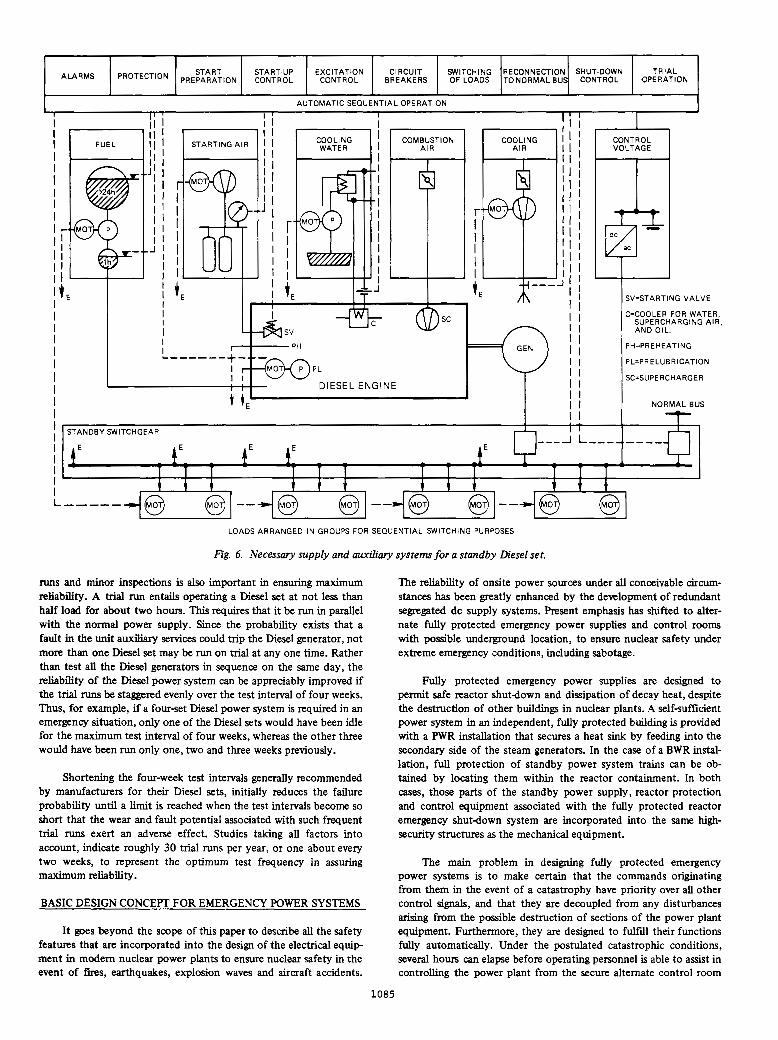
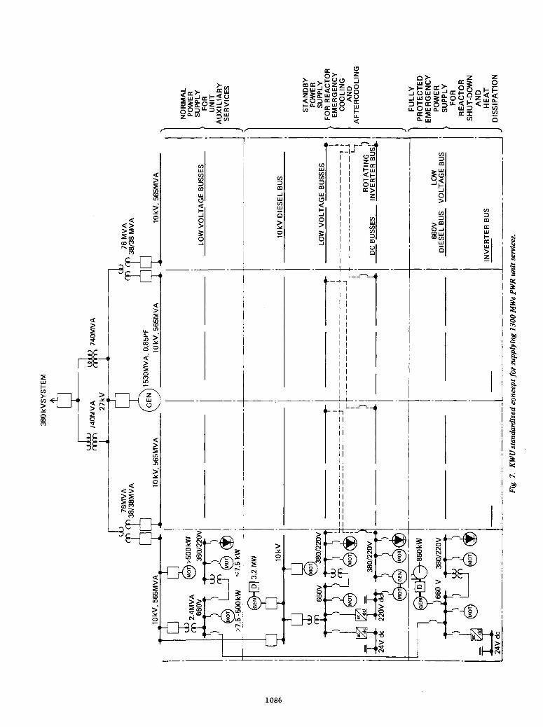
Figures 7 and 8 depict the latest concepts of the author’s company for supplying power to the unit services of 1300 Mw-class light-water reactors, both PWR and BWR types, under all normal and abnormal operating conditions. Both achieve the rigorous physical and electrical separation of the various ac and dc power supply buses, as already described in this paper. They are provided with basically the same four-train auxiliary services supply systems. How- ever, the standby and fully protected emergency power systems are different, primarily because the design of the reactor emergency cooling and aftercooling are not the same.
The power supply concept for PWR installations is based on the reactor having four 5WAuty emergency cooling and aftercooling equipment trains. Each such train is equipped with its own standby power supply comprising a Diesel set, as well as batteries and in- verters. In addition, each train is provided with an independent fully protected emergency power supply with its own small Diesel set and dc equipment.
The BWR power supply concept is drawn up on the basis of the reactor having three full-capacity emergency cooling and aftercooling equipment trains. A separate standby power supply system, con- sisting of a Diesel set and dc equipment, is allocated to each train. Two of these also serve as emergency power supplies. They are fully protected by being located within two physically separate buildings inside the reactor containment. Two additional complete standby power supplies are provided that are not dedicated to any of the three trains of mechanical equipment. These two, plus the one not located inside the reactor containment, are accommodated in their own separate building.
CONCLUSIONS
The unprecedented severity in the reliability requirements for power supply to all safety related equipment in nudear power plants under force majeure circumstances, has led to the provision of two levels of onsite power and controls, namely standby and emergency. Maximum reliability is obtained by allocating a completely inde- pendent power supply to each of the redundant trains of mechanical equipment and by strictly enforcing a comprehensive program of tests, inspections and maintenance at regular optimized intervals. It is considered more important to concentrate on securing the greatest possible reliability of the onsite standby and emergency power sys- tems, rather than depend to any large extent on the dubious reli- ability of a second source of offsite power. Unlike external power feeders, onsite Diesel power systems can be optimized to attain the highest degree of reliability. In the f d analysis, the safety of nu- clear power plants rests on the correct functioning of the onsite power sources when emergencies arise.
REFERENCES
(1) DIN 25 417 B1. 4 (draft), Beuth-Vertrieb, Berlin 30, July 1973.
( 2 ) A. Borst, “Power supply for nuclear plants and USAEC criteria”, translation published by Kraftwerk Union AG (Order No. KWU 164-101) of article in “Elektrizitaetswirtschaft”, vol. 15, pp. 450452,1972.
(3) A. Borst, “Electrical equipment associated with the 1200 MW Biblis-1 nuclear power plant”, IEEE paper C72 243-9, presented in New York on Feb. 4, 1972.
(4) DIN 25 417 B1.5 (draft), Beuth-Vertrieb, Berlin 30, July 1974.
1088
Discussion
Robert N. Carson and Daniel J. Love (Bechtel Power Corp., Los Angeles Division, Norwalk, Ca.): The author should be hghly commended for his paper which should be required reading for design, regulatory, and oper- ating personnel in the electric generating industry. Some excellent points are made concerning the German approach to standby systems which could provide cost and reliability advantages over the present U.S.A. practices.
The method of using loss-of-voltage on the standby bus as the only criterion for starting the dieselgenerators is considered superior to the current U.S.A. practice of loss-of-voltage and/or a LOCA signal.
In discussing Figure 3, the author states it is U.S. practice to estab- lish a second standby power source within six hours of a prolonged unit outage. However, IEEE Std 308-1974 removes the time period (was actually eight hours) in describing the provision for alternate delayed access to the transmission network. AEC Regulatory Guide 1.32 states that the preferred design would include two immediate access standby sources. Acceptable criteria for the alternate delayed access circuit is that it be available in sufficient time for its function.
When the generator breaker is open, and power flows from the transmission system through the main transformers and the 27 kV bus to the auxiliary transformers, there is no ground detection scheme in service on the 27 kV bus. During normal operation, a 27 kV bus ground fault can be detected by the WYE-Broken Delta scheme. Although the generator bus grounding is not discussed, consideration of the different approaches should be made. U.S.A. practice generally utilizes a high resistance grounded neutral. An alternate approach when using a gener- ator breaker would be to use a grounding transformer on the 27 kV bus.
In the paper, the author has made some recommendations that could be extremely beneficial if the support reference were available. In particular:
1. Could the author identify the source for the comparative relia- bility analyses referenced above Figure 3? Little data on system com- ponent reliability is available in the USA. which rmght be used in the calculation of nuclear power plant electric system reliability or avail- ability.
2. Could the author clarify the methods used by German manu-
there are relevant German Standards (DIN), please identify. facturers to qualify Diesel-generator sets for nuclear power plant use? If
3. Could the author provide data on expected plant cooldown time in order to support the use of small capacity Dieselgenerator fuel tanks. IEEE Std 308-1974 requires a seven days storage capacity or equivalent approach, whereas the author considers a one day supply as sufficient. (See page 5 )
gation leading to a failure rate better than 10-2 for Diesel sets? (See 4. Could the author provide a reference for the statistical investi-
Reliability of Diesel Power Systems on page 5). Furthermore, is there
and that 30 trial runs per year is an optimum number of tests? any reference for the statements that in-place repairs average 2-3 days,
With the inclusion of the references to support the paper’s recom- mendations, we feel that a substantial contribution will have been made to nuclear power plant design, cost, and reliability. Even without such references, the author has made a valuable alternative for plant design.
Manuscript received October 8,1975.
J. Krasnodebski and M. S. Grover (Ontario Hydro, Toronto, Ontario, Canada): The author is to be commended for a very interesting and in- formative paper. Some important differences in the design philosophy
are pointed out. The author notes that German plant designers place of electrical power supplies of German and US nuclear power stations
much more emphasis on the reliability of onsite power sources than US power plant designers who rely heavily on offsite power sources. The provision of a generator circuit breaker and the division of Diesel power system into segregated redundant trains can add significantly to the re- liability of standby power supplies. The design concepts described in the paper to enhance the reliability of standby and emergency power sys- tems of German nuclear stations are very useful.
We would like to discuss the following points with the author. (a) It is stated in the paper that circuit designs shown in Figures
2 and 3 are equivalent from a reliability viewpoint. We would like to
what results were obtained. know whether a qualitative or a quantitative analysis was performed and
(b) Do the German utilities design the standby and emergency power supplies to achieve a quantitative reliability target? If so, what is the value of the target?
(c) It appears from the paper that the standby and emergency power supplies are meant to supply loads for nuclear safety only. What
very critical from nuclear safety viewpoint but failures of which can power supplies are used in Bibb unit to supply the loads which are not
cause serious damage to the station equipment? Manuscript received October 8, 1975.
(d) T h e author states that the reliability of Dieser power system is an order of magnitude better when the Diesel sets are strictly segregated rather than being intermeshed with each other. This appears to be quite reasonable since the associated transfer schemes will be very simple and will require small number of operations. However, the cost of the Diesel power system may increase significantly.
(e) What are demonstrated values of availability, starting and running reliability of diesel units in German nuclear stations in general and in Biblis “A” unit in particular? It is stated in Reference 1 of this discussion that the probability of successful performance of a diesel unit in U.S.A., as computed from surveillance-test data, is less than 0.95 at a
this apparent differnce in German and US. experience. confidence level of 50%. We would appreciate author’s comments on
(0 The author states that emergency power systems for PWR plants are supplied using small Diesel sets and 24 V dc equipment where- as for BWR plants emergency power systems involve large diesel sets and dc supplies. We would like to know the reasons for usingdifferent ar- rangements for PWR and BWR plants.
In conclusion, we again compliment the author for his valuable contribution.
REFERENCE
[ 1 ] “DieselGenerator Operating Experience at Nuclear Power Plants.” Nuclear Safety, Vol. 16, No. 2, March-April 1975, pp. 224-227.
Alexander Borst: The author wishes to thank the discussers for their complimentary remarks. He is grateful to Messrs. Carson and Love for pointing out the slip in giving six, not eight hours, as the time interval in which a second offsite power supply h a to be established in: the event of a prolonged unit outage. However, this had already become irrelevant since the IEEE Standard 308-1974 replaced the words “eight hours” by “in sufficient time.” It is German practice to employ a wye/ opendelta potential transformer, not to ground the generator neutral, for generator ground-fault detection purposes. This same type of P.T. is installed at the low-voltage side of each of the half-size main transform- ers to detect ground faults on the 27 kv busbar system, regardless of whether the generator is connected or not. Clarification of the four points raised by Messrs. Carson and Love is given below with support references:
1. In the course of planning the Biblis “A” unit, the turnkey plant supplier, Kraftwerk Union AG (KWU), the utility, Rheinisch-West- faelisches Elektrizitaetswerk AG (RWE), the Technical Supervisory Society (TUeV) of Bavaria and the Institute for Reactor Safety (IRS) all carried out reliability analyses that led to the same conclusion, namely, the reliability of a single external feeder in conjunction with a low-voltage generator breaker (Fig. 3) is practically equal to two in- dependent external feeders (Fig. 2). The results of these comparative analyses and the methods of calculating the reliability of other systems, e.g. emergency power supply, are discussed on Pages 86 to 88 in the 1972 IRS Annual Report (Taetigkeitsbericht). The same comparative analyses for the Kalkar fast breeder reactor (SNR 300) confmed the results reached in the Biblis studies. Dr. H. Zeibig of INTERATOM published these fmdings in the revised reprint of his lecture to the 1973 Reactor Conference in Karlsruhe under the title “Zuverlaessigkeitskon- trolle im Reaktorbau” that appeared in the August/September 1973 issue of “Atomwirtschaft” (see Page 405 and Figs. 11 and 12). Details of the component availability data, on which such analyses are based, were presented by Messrs. F. W. Heuser and H. Werner of INTERATOM and by he. P. Hoemke of IRS at the Reactor Conferences in 1972 and 1974, respectively. The component failure rates are derived mostly from
German utilities. In addition, IRS established in 1973 a separate com- the statistics compiled by VDEW over many years from the reports of
ponent failure data collecting system. 2. The DIN Standard 25 417 Blatt 5 (draft dated July 1975) given
in Reference (4) is the detailed basis that is used to qualify Diesel- generator sets. Compliance with the final edition of this standard will shortly be enforced by law in all German nuclear power plants.
year. Not this time, but the longest outage time of the normal power 3. The cooldown time for a light-water reactor can last up to a
supply to the unit auxiliaries and emergency services determines the necessary fuel storage capacity. Such outages generally last only a few hours. However, in order to guard against an improbably long intermp tion of the normal power supply under the worst possible conditions, the more conservative criterion of the longest time required to refd the storage tank under the most difficult circumstances is adopted. This leads the authorities in Germany to require that each of all the Diesel engines in a nuclear power plant be provided with a fuel storage capacity to allow full-load operation for 72 hours or three full days. The corresponding stipulation of seven days in IEEE Standard 308- 1974 is presumably due to the fact that climatic disturbances can be
Manuscript received December 5,1975.
1089
more extremely severe and means of transportation more difficult in the U.S. than in Central Europe. The minimum time of 24 hours given in the aforementioned DIN Standard 25 417 Blatt 5 is purposely kept so small, because this standard is also applicable to nuclear research re- actors, some of which can dispense with a standby power supply after a short period.
by a German committee (Fachnormenausschuss Kerntechnik), of which 4. The data given in the paper are derived from statistics collected
the author is a member, from the operators of research and commercial nuclear installations. They cover 22 Diesel sets with a total of 107 unit- years of service which accumulated just over 3700 starts, 13 of which were unsuccessful. The longest repair time was three days, the average less than two days. These statistics have not been published, but are available to the German licensing authorities.
discussion items submitted by Messrs. Krasnodebski and Grover: The author offers the following information in response to the six
son was carried out qualitatively, employing fault-tree analysis methods (a) As can be gleaned from Point 1 above, the reliability compari-
in accordance with the DIN Standard 25 424. The sources of the com- ponent failure rates used are stated under Point 1. The applied analytical methods are explained in Section 4 and the results of the reliability
tioned article by Dr. Zeibig in the AugustlSeptember 1973 issue of comparison are given in Subsection 5.1 (see Fig. 12) of the aforemen-
“Atomwirtschaft”. The failure probability of the standby busses as a function of the time in service was determined to be practically the same for both power circuitry schemes, lying between 10-6 and 10-8. This qualitative analysis to determine whether one of the two schemes is actually superior, was performed after both were found to fulfill quan- titatively the singlefault criterion to assure reliable standby power supply *
on the fulfiument of the singlefault criterion as the prerequisite for (b) The German licensing authorities insist right from the outset
adequate quantitative reliability. The safety criteria of the Federal Ministry of the Interior and the guidelines of the Reactor Safety Com- mission for light-water reactors all require that the cooling system must perform its safety function when a single fault occurs while equipment in the system is being either tested or repaired. They also impose the same basic performance requirement (nt2) in the case of the standby power supply.
(c) The purpose of the paper was to show how the design of the standby and emergency power supply sydems, especially the number of Diesel sets and busses, as well as the segregation into separate equipment trains, is established by the ‘emergency cooling and aftercooling require- ments for nuclear safety. Of course, less critical loads are also connected
to the standby power supply busses, often with a lesser than fourfold redundancy. However, such loads that are not so critical from a nuclear safety standpoint do not affect the basic power supply design concept, but they must be fully taken into account when seeking approval of the standby power balance.
(d) Experience indicates that strict segregation of Diesel sets, as required by the German licensing authorities, not only ipcreases reliabil- ity, but also can result in savings, provided that the principal safety sys- tems are also arranged in separate trains. Intermeshing of Diesel sets can
mode failures is either neglected or rated low. However, the possibility only be considered to enhance reliability if the possibility of common-
of such failures arising from external disturbances and natural catastro- phies with resultant serious effect on intermeshed power supply systems, is judged to be grave. The economic advantage lies in the fact that segregation confronts each Diesel set with a better defined and lesser
plied from any one of two or three sets, which necessitates doubling or capability requirement. By intermeshing Diesel sets, loads can be sup
tripling the investiment for Diesel power capability.
be stated that the direct injection of compressed air into the cylinders (e) Supplementing the statistics given under Point 4 above, it can
of 1500 rpm Diesel engines, as is standard German practice, is consider- ably more reliable than using, for instance, electrical starting devices. The latest statistics of German utility experience confm that the start - up reliability of such high+pe,ed Diesel sets is better than 10-2, namely only one failure to start out of more than 100 successful starts.
(f) The two different standardized standby and emergency power supply arrangements (Figs. 7 and 8) are due to the differences in design between the author’s company’s PWR and BWR plants. The reactor emergency cooling equipment is divided into four 5Wmpability trains for PWR plants and into three IWmpabi l i ty trains for BWR plants, thus fulfilling in both cases the performance requirement of nt2. The reactor building of each type offers full protection against external dis- turbances, e.g. airm-ft crashes, explosion waves, etc. Two of the three BWR standby power supplies are fully protected by being. accom- modated in the reactor building. However, this is not possible with the
space is occupied by additional PWR related equipment, mainly four corresponding PWR because, although its containment is larger, its inner
this reason, in addition to the four PWR standby power supplies in- steam generators, four reactor coolant pumps and one pressurizer. For
stalled in an unprotected switchgear building, four separate emergency power supplies, each with a small Diesel set and 24V dc equipment, are provided for shutting down the reactor and dissipating its heat in the case of an emergency, and they are fully protected against external disturbances by being installed in a highsecurity bunker.
1090

![Standby Power Systems - UNSJdea.unsj.edu.ar/ihospitalarias/Power Quality in... · assembled into standby power systems for critical loads and systems. They include the following [13.1]:](https://img.pdfslide.net/doc/110x75/5eb7ec6a44b6e07038322bc3/standby-power-systems-quality-in-assembled-into-standby-power-systems-for.jpg)