Embed Size (px)
Citation preview
micromachines
Article
Standing Air Bubble-Based Micro-HydraulicCapacitors for Flow Stabilization in SyringePump-Driven Systems
Yidi Zhou 1,2 , Jixiao Liu 1,2,3,*, Junjia Yan 1,2, Tong Zhu 1,2, Shijie Guo 1,2, Songjing Li 4 andTiejun Li 1,2
1 School of Mechanical Engineering, Hebei University of Technology, Tianjin 300132, China;[email protected] (Y.Z.); [email protected] (J.Y.); [email protected] (T.Z.);[email protected] (S.G.); [email protected] (T.L.)
2 Hebei Key Laboratory of Robot Perception and Human-Robot Interaction, Hebei University of Technology,Tianjin 300401, China
3 Department of Bioengineering, University of California, Berkeley, CA 94720, USA4 School of Mechatronics, Harbin Institute of Technology, Harbin 150001, China; [email protected]* Correspondence: [email protected]; Tel.: +86-185-2209-9429
Received: 18 February 2020; Accepted: 8 April 2020; Published: 10 April 2020�����������������
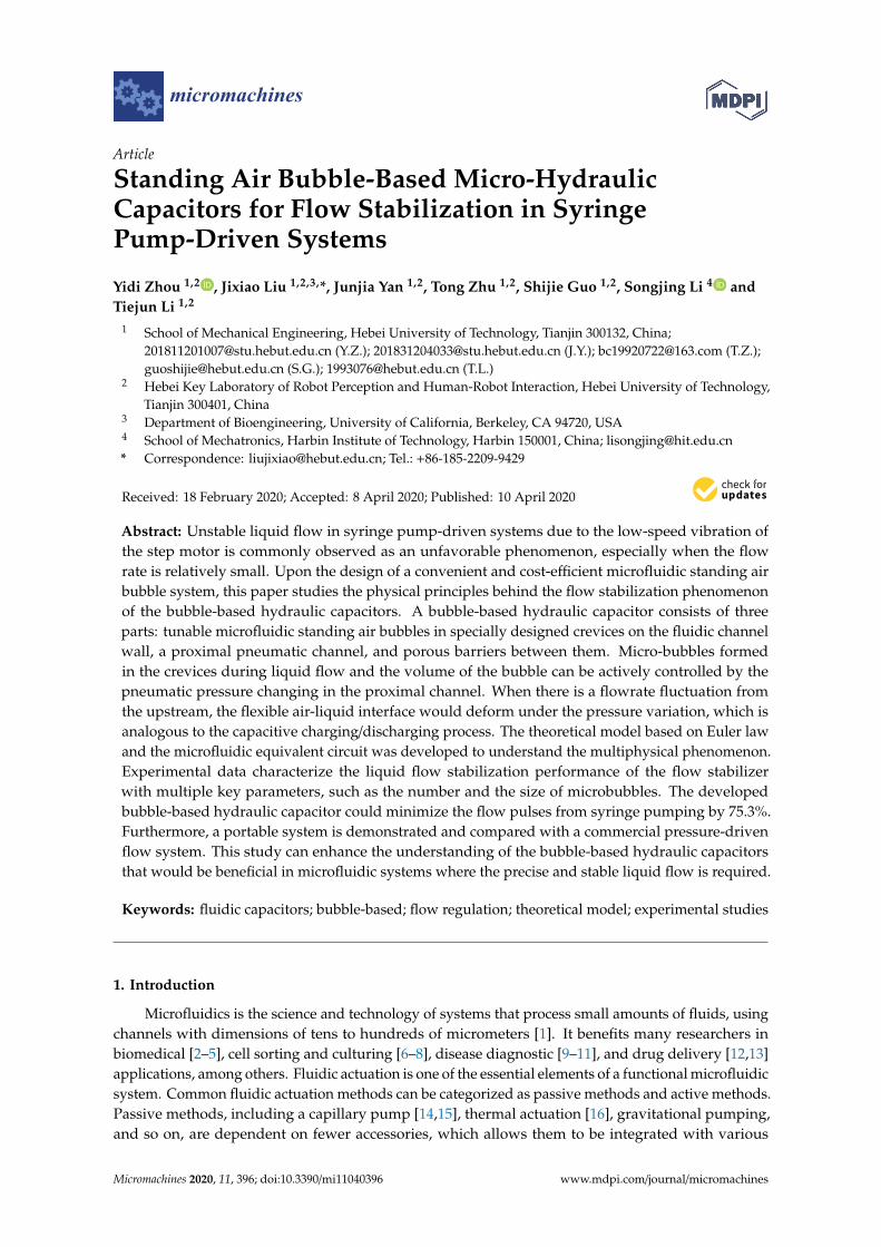
Abstract: Unstable liquid flow in syringe pump-driven systems due to the low-speed vibration ofthe step motor is commonly observed as an unfavorable phenomenon, especially when the flowrate is relatively small. Upon the design of a convenient and cost-efficient microfluidic standing airbubble system, this paper studies the physical principles behind the flow stabilization phenomenonof the bubble-based hydraulic capacitors. A bubble-based hydraulic capacitor consists of threeparts: tunable microfluidic standing air bubbles in specially designed crevices on the fluidic channelwall, a proximal pneumatic channel, and porous barriers between them. Micro-bubbles formedin the crevices during liquid flow and the volume of the bubble can be actively controlled by thepneumatic pressure changing in the proximal channel. When there is a flowrate fluctuation fromthe upstream, the flexible air-liquid interface would deform under the pressure variation, which isanalogous to the capacitive charging/discharging process. The theoretical model based on Euler lawand the microfluidic equivalent circuit was developed to understand the multiphysical phenomenon.Experimental data characterize the liquid flow stabilization performance of the flow stabilizerwith multiple key parameters, such as the number and the size of microbubbles. The developedbubble-based hydraulic capacitor could minimize the flow pulses from syringe pumping by 75.3%.Furthermore, a portable system is demonstrated and compared with a commercial pressure-drivenflow system. This study can enhance the understanding of the bubble-based hydraulic capacitorsthat would be beneficial in microfluidic systems where the precise and stable liquid flow is required.
Keywords: fluidic capacitors; bubble-based; flow regulation; theoretical model; experimental studies
1. Introduction
Microfluidics is the science and technology of systems that process small amounts of fluids, usingchannels with dimensions of tens to hundreds of micrometers [1]. It benefits many researchers inbiomedical [2–5], cell sorting and culturing [6–8], disease diagnostic [9–11], and drug delivery [12,13]applications, among others. Fluidic actuation is one of the essential elements of a functional microfluidicsystem. Common fluidic actuation methods can be categorized as passive methods and active methods.Passive methods, including a capillary pump [14,15], thermal actuation [16], gravitational pumping,and so on, are dependent on fewer accessories, which allows them to be integrated with various
Micromachines 2020, 11, 396; doi:10.3390/mi11040396 www.mdpi.com/journal/micromachines
Micromachines 2020, 11, 396 2 of 11
devices. However, these passive methods usually fail to offer a well-controlled and consistent flow forpractical applications.
Syringe pumps [17], pressure-driven pumps [18], and peristaltic pumps [19,20] are the mostcommonly used active pumping methods for microfluidic systems [21]. The syringe pump is the topoption when the precisely controlled flow is required. However, the syringe pumps sometimes produceundesirable and insurmountable pressure pulses when working in low-flowrate conditions [22], dueto the mechanical vibration from the stepper motor or poor maintenance. Therefore, the stability andaccuracy of the syringe pump-driven flow are required to be improved for applications such as dropletand bubble generation [22,23].
Three categories of approaches were developed to provide stabilized flow with fewer pulses andfluctuations in syringe pump systems. One is to form several dampers serving as fluidic capacitanceor cushions to minimal the fluidic fluctuations. The dampers are formed using either soft compliantmaterial [24–26] or compressible air [21,27,28]. One is to deploy variation flow resistors to stabilize theunstable sample flow [29], and the other is to use magnetic [30] or electric actuators [31]. Much effort isdevoted to attenuating syringe pump-induced fluctuations. However, there is comparatively littleattention paid to theories to understand the flow stabilization process, as well as the manufacturabilityand integrability of the hydraulic stabilization device with an on-chip system.
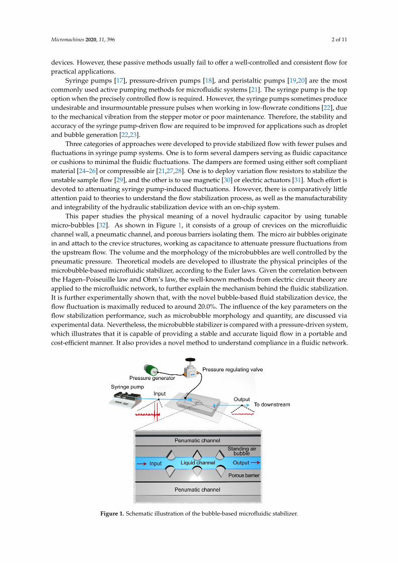
This paper studies the physical meaning of a novel hydraulic capacitor by using tunablemicro-bubbles [32]. As shown in Figure 1, it consists of a group of crevices on the microfluidicchannel wall, a pneumatic channel, and porous barriers isolating them. The micro air bubbles originatein and attach to the crevice structures, working as capacitance to attenuate pressure fluctuations fromthe upstream flow. The volume and the morphology of the microbubbles are well controlled by thepneumatic pressure. Theoretical models are developed to illustrate the physical principles of themicrobubble-based microfluidic stabilizer, according to the Euler laws. Given the correlation betweenthe Hagen–Poiseuille law and Ohm’s law, the well-known methods from electric circuit theory areapplied to the microfluidic network, to further explain the mechanism behind the fluidic stabilization.It is further experimentally shown that, with the novel bubble-based fluid stabilization device, theflow fluctuation is maximally reduced to around 20.0%. The influence of the key parameters on theflow stabilization performance, such as microbubble morphology and quantity, are discussed viaexperimental data. Nevertheless, the microbubble stabilizer is compared with a pressure-driven system,which illustrates that it is capable of providing a stable and accurate liquid flow in a portable andcost-efficient manner. It also provides a novel method to understand compliance in a fluidic network.
Micromachines 2020, 11, x 2 of 11
active methods. Passive methods, including a capillary pump [14,15], thermal actuation [16], gravitational pumping, and so on, are dependent on fewer accessories, which allows them to be integrated with various devices. However, these passive methods usually fail to offer a well-controlled and consistent flow for practical applications.
Syringe pumps [17], pressure-driven pumps [18], and peristaltic pumps [19,20] are the most commonly used active pumping methods for microfluidic systems [21]. The syringe pump is the top option when the precisely controlled flow is required. However, the syringe pumps sometimes produce undesirable and insurmountable pressure pulses when working in low-flowrate conditions [22], due to the mechanical vibration from the stepper motor or poor maintenance. Therefore, the stability and accuracy of the syringe pump-driven flow are required to be improved for applications such as droplet and bubble generation [22,23].
Three categories of approaches were developed to provide stabilized flow with fewer pulses and fluctuations in syringe pump systems. One is to form several dampers serving as fluidic capacitance or cushions to minimal the fluidic fluctuations. The dampers are formed using either soft compliant material [24–26] or compressible air [21,27,28]. One is to deploy variation flow resistors to stabilize the unstable sample flow [29], and the other is to use magnetic [30] or electric actuators [31]. Much effort is devoted to attenuating syringe pump-induced fluctuations. However, there is comparatively little attention paid to theories to understand the flow stabilization process, as well as the manufacturability and integrability of the hydraulic stabilization device with an on-chip system.
This paper studies the physical meaning of a novel hydraulic capacitor by using tunable micro-bubbles [32]. As shown in Figure 1, it consists of a group of crevices on the microfluidic channel wall, a pneumatic channel, and porous barriers isolating them. The micro air bubbles originate in and attach to the crevice structures, working as capacitance to attenuate pressure fluctuations from the upstream flow. The volume and the morphology of the microbubbles are well controlled by the pneumatic pressure. Theoretical models are developed to illustrate the physical principles of the microbubble-based microfluidic stabilizer, according to the Euler laws. Given the correlation between the Hagen–Poiseuille law and Ohm’s law, the well-known methods from electric circuit theory are applied to the microfluidic network, to further explain the mechanism behind the fluidic stabilization. It is further experimentally shown that, with the novel bubble-based fluid stabilization device, the flow fluctuation is maximally reduced to around 20.0%. The influence of the key parameters on the flow stabilization performance, such as microbubble morphology and quantity, are discussed via experimental data. Nevertheless, the microbubble stabilizer is compared with a pressure-driven system, which illustrates that it is capable of providing a stable and accurate liquid flow in a portable and cost-efficient manner. It also provides a novel method to understand compliance in a fluidic network.
Figure 1. Schematic illustration of the bubble-based microfluidic stabilizer.
Micromachines 2020, 11, 396 3 of 11
2. Microbubble Formation and Control
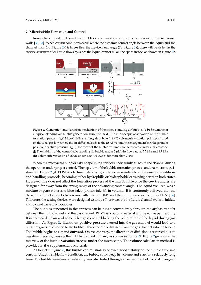
Researchers found that small air bubbles could generate in the micro crevices on microchannelwalls [33–35]. When certain conditions occur where the dynamic contact angle between the liquid and thechannel walls (αin Figure 2a) is larger than the crevice inner angle (βin Figure 2a), there will be air left in thecrevice structure after liquid flows by, since the liquid cannot fill all the space inside, as shown in Figure 2b.
Micromachines 2020, 11, x 3 of 11
Figure 1. Schematic illustration of the bubble-based microfluidic stabilizer.
2. Microbubble Formation and Control
Researchers found that small air bubbles could generate in the micro crevices on microchannel walls [33–35]. When certain conditions occur where the dynamic contact angle between the liquid and the channel walls (𝛼 in Figure 2a) is larger than the crevice inner angle (β in Figure 2a), there will be air left in the crevice structure after liquid flows by, since the liquid cannot fill all the space inside, as shown in Figure 2b.
When the microscale bubbles take shape in the crevices, they firmly attach to the channel during the operation under proper control. The top view of the bubble formation process under a microscope is shown in Figure 2c,d. PDMS (Polydimethylsiloxane) surfaces are sensitive to environmental conditions and handling protocols, becoming either hydrophilic or hydrophobic or varying between both states. However, this does not affect the formation process of the microbubble once the crevice angles are designed far away from the swing range of the advancing contact angle. The liquid we used was a mixture of pure water and blue inkjet printer ink, 5:1 in volume. It is commonly believed that the dynamic contact angle between normally made PDMS and the liquid we used is around 105° [36]. Therefore, the testing devices were designed to array 60° crevices on the fluidic channel walls to initiate and control these microbubbles.
The bubbles generated in the crevices can be tuned conveniently through the air/gas transfer between the fluid channel and the gas channel. PDMS is a porous material with selective permeability. It is permeable to air and some other gases while blocking the penetration of the liquid during gas diffusion. As Figure 2e illustrates, positive pressure exerted into the gas channel would lead to a pressure gradient directed to the bubble. Thus, the air is diffused from the gas channel into the bubble. The bubble begins to expand outward. On the contrary, the direction of diffusion is reversed due to negative pressure, causing the bubble to shrink inward, as shown in Figure 2f. Figure 2g–i shows the top view of the bubble variation process under the microscope. The volume calculation method is provided in the Supplementary Materials.
As found in Figure 2j, this bubble control strategy showed good stability on the bubble’s volume control. Under a stable flow condition, the bubble could keep its volume and size for a relatively long time. The bubble variation repeatability was also tested through an experiment of cyclical change of bubble volume for a relatively long time. The pressure in the pneumatic channel was periodically shifted between −30 kPa and 30 kPa, and the periodic variation of bubble volume was as shown in Figure 2k. The bubbles shrank or expanded at a nearly constant rate, in each pressure cycle. At the same time, the volume of the bubble remained stable within a range from 2.5 × 105 μm3 to 4.5 × 105 μm3. Furthermore, it can be found that both the volume variation rate and change illustrated a uniformity during each positive or negative pressure interval.
Figure 2. Generation and variation mechanism of the micro standing air bubble. (a,b) Schematic ofa typical standing air bubble generation structure. (c,d) The microscopic observation of the bubbleformation process. (e,f) Microfluidic standing air bubble (µSAB) volumetric variation principle, basedon the ideal gas law, where the air diffusion leads to the µSAB volumetric enlargement/shrinkage underpositive/negative pressure. (g–i) Top view of the bubble volume change process under a microscope.(j) The stability of the controllable standing air bubble under 5 µL/min flow rate at 7.5 kPa and 6.7 kPa.(k) Volumetric variation of µSAB under ±30 kPa cycles for more than 700 s.
When the microscale bubbles take shape in the crevices, they firmly attach to the channel duringthe operation under proper control. The top view of the bubble formation process under a microscope isshown in Figure 2c,d. PDMS (Polydimethylsiloxane) surfaces are sensitive to environmental conditionsand handling protocols, becoming either hydrophilic or hydrophobic or varying between both states.However, this does not affect the formation process of the microbubble once the crevice angles aredesigned far away from the swing range of the advancing contact angle. The liquid we used was amixture of pure water and blue inkjet printer ink, 5:1 in volume. It is commonly believed that thedynamic contact angle between normally made PDMS and the liquid we used is around 105◦ [36].Therefore, the testing devices were designed to array 60◦ crevices on the fluidic channel walls to initiateand control these microbubbles.
The bubbles generated in the crevices can be tuned conveniently through the air/gas transferbetween the fluid channel and the gas channel. PDMS is a porous material with selective permeability.It is permeable to air and some other gases while blocking the penetration of the liquid during gasdiffusion. As Figure 2e illustrates, positive pressure exerted into the gas channel would lead to apressure gradient directed to the bubble. Thus, the air is diffused from the gas channel into the bubble.The bubble begins to expand outward. On the contrary, the direction of diffusion is reversed due tonegative pressure, causing the bubble to shrink inward, as shown in Figure 2f. Figure 2g–i shows thetop view of the bubble variation process under the microscope. The volume calculation method isprovided in the Supplementary Materials.
As found in Figure 2j, this bubble control strategy showed good stability on the bubble’s volumecontrol. Under a stable flow condition, the bubble could keep its volume and size for a relatively longtime. The bubble variation repeatability was also tested through an experiment of cyclical change of
Micromachines 2020, 11, 396 4 of 11
bubble volume for a relatively long time. The pressure in the pneumatic channel was periodicallyshifted between −30 kPa and 30 kPa, and the periodic variation of bubble volume was as shown inFigure 2k. The bubbles shrank or expanded at a nearly constant rate, in each pressure cycle. At thesame time, the volume of the bubble remained stable within a range from 2.5 × 105 µm3 to 4.5 ×105 µm3. Furthermore, it can be found that both the volume variation rate and change illustrated auniformity during each positive or negative pressure interval.
3. Theoretical Modeling of Flow Stabilization
3.1. Theoretical Model
The working principle of the bubble-based microfluidic stabilizer could be explained as outlinedbelow. During an overflow, the air bubbles shrink in size, squeezed by the fluidic pressure. Thus,the pulse induced by the syringe pump can be weakened. As for underflow, the air bubbles begin toexpand due to the pressure drop in the liquid channel, offsetting the decrease in flowrate. With thesetwo statements, the fluctuation in flowing conditions can be eliminated, when fluid passes through themicrofluidic stabilizer.
As shown in Figure 3a, in the steady state, the pressure in the conjunction of the bubble and themain channel is p, with the flowrate of Q0 in the main channel, while ρ is the density of the fluid.According to the Euler laws, the force can be derived as follows:
dQ0
dtρl1 = (p−Q0R1)A1 = 0, (1)
where A1 is the cross-sectional area of the main channel, l1 is the length of the main channel, and R1 isthe flow resistance of the main channel. The flowrate has a sharp increase in the upstream, resulting ina pressure increase ∆p in the conjunction. Suppose the increased flowrate is ∆Q. The force balance inthe main channel can be derived as follows:
d(Q0 + ∆Q1)
dtρl1 = (p + ∆p−Q0R1 − ∆Q1R1)A1 = 0, (2)
d∆Q1
dtρl1 = (∆p− ∆Q1R1)A1, (3)
where ∆Q1 is the increased flowrate in the downstream of the main channel. Through Laplacetransformation, we obtain
∆p(s) =ρl1∆Q1
A1s + ∆Q1R1. (4)
We considered the bubble as a mass-spring system. Considering that the temperature balance canbe achieved in a very short time, and the mass diffusion process is quite short, the ideal gas law for theisothermal condition is given as pVγ = const(γ = 1). The pressure in the bubble is pb = p0[V0/(V0 − ∆V)]= p0(1 − l2A2/V0). p0 is the initial pressure in the bubble, and V0 is the initial volume of the bubble. A2
is the cross-section area of the bubble crevice open area. l2 is the height of the bubble shrinkage, asshown in Figure 3a. For the mass-spring system, the stiffness coefficient is k = p0A2
2/V0, l2 =∫
∆Q2/A2
dt. The force balance between the bubble and fluid is given as
d∆Q2
dtρl2 = kl2 − ∆pA2, (5)
where ∆Q2 is the amount of flowrate to press the bubble. Through Laplace transformation, we obtain
∆p(s) =p0
V0
∆Q2
s−ρl2Q2
A2s. (6)
If we set A1 = 2A2 = 2A, the stabilization ratio λ is
Micromachines 2020, 11, 396 5 of 11
λ =∆Q1
∆Q1 + ∆Q2=
p0AV0− 2ρl2s2
ρ(l1 − 2l2)s2 + 2AR1s + p0AV0
. (7)
Under the condition of slow flowrate in this paper, l2 is much lower than l1. It could be considerednegligible. Therefore, the stabilization ratio λ can be rearranged as follows:
λ =p0
ρV0A s2 + 2V0R1s + p0
. (8)
From the equation above, it is clear that the stabilizer can function as a fluidic stabilizer in a lab-on-chipsystem, which can minimize the fluctuation from the upstream. The stabilization effect is mainly affectedby V0. Here, the volume of the bubble can be tuned easily using both the pressure in the pneumaticchannel and the number of crevices on the channel. Thus, the device can be applied in different situations.
Micromachines 2020, 11, x 5 of 11
If we set A1 = 2A2 = 2A, the stabilization ratio λ is
202
01
2 01 21 2 1
0
2
( 2 ) 2
p A l sVQ
p AQ Q l l s AR sV
ρλ
ρ
−Δ= =
Δ + Δ − + +.
(7)
Under the condition of slow flowrate in this paper, l2 is much lower than l1. It could be considered negligible. Therefore, the stabilization ratio λ can be rearranged as follows:
0
200 1 02
pV s V R s pA
λ ρ=+ +
. (8)
From the equation above, it is clear that the stabilizer can function as a fluidic stabilizer in a lab-on-chip system, which can minimize the fluctuation from the upstream. The stabilization effect is mainly affected by V0. Here, the volume of the bubble can be tuned easily using both the pressure in the pneumatic channel and the number of crevices on the channel. Thus, the device can be applied in different situations.
Figure 3. The mechanism of the μSAB flow stabilization effect: (a) the model to understand the effect of bubbles on the reduction of fluctuations; (b) the model for the simulation in COMSOL
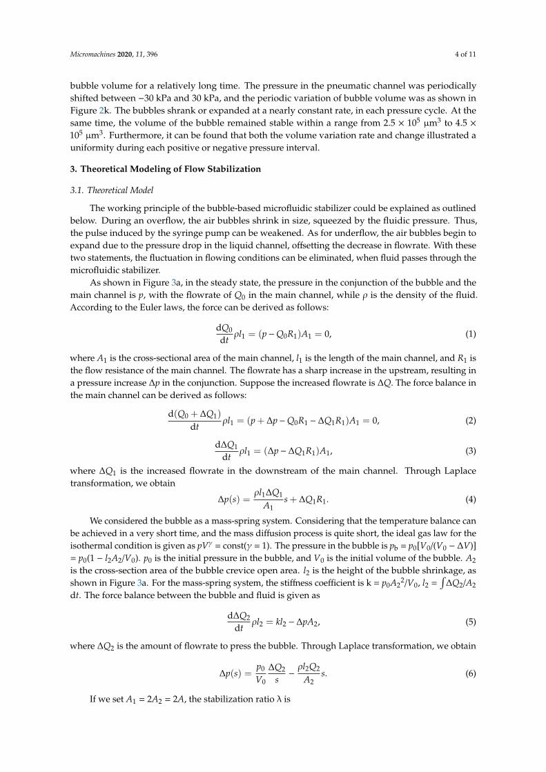
Figure 3. The mechanism of the µSAB flow stabilization effect: (a) the model to understand the effectof bubbles on the reduction of fluctuations; (b) the model for the simulation in COMSOL Multiphysics,and the storage and release process of the bubble-based damper. Here, part of the fluid will press thebubble for an overflow, and the fluid stored in the space of the bubble will be released back into theliquid channel for an underflow; (c) the flowrate velocity magnitude results of the simulation; (d) thebubble variation results of the simulation.
3.2. Finite Element Analysis
A numerical simulation was conducted in the COMSOL Multiphysics (Version 5.5, Stockholm,Sweden.) to further illustrate the principle of the introduced device for the flow regulation. The model
Micromachines 2020, 11, 396 6 of 11
established for the calculation is illustrated in Figure 3b. The width of the channel (w) was 150 µm, andthe length of the channel (l) was 300 µm. The diameter (D) of the bubble was 60 µm, and the drivenpressure pin = 20 + 10sin(106t) Pa. Two boundary probes were added to the inlet and outlet to obtainthe velocity magnitude. Probe 1 stands for the inlet, while Probe 2 stands for the outlet. The two-phaseflow was simulated using the level-set method.
When in the steady state, all the fluid flowing into the stabilizer will flow along the main channelto the outlet. Part of the fluid will press the bubble for an overflow, and the fluid stored in the spaceof the bubble will be released back into the liquid channel for an underflow, as shown in Figure 3b.Figure 3c demonstrates the flowrate velocity magnitude results at the inlet and outlet. Through thedepicted curve, the input fluctuation is effectively surpassed. Figure 3d shows the variation of thebubble size. It is shown that the bubble size changes with the input flowrate, leading to a relativelystable flowrate at the output. Thus, the bubble-based fluidic stabilizer can function as a fluidic stabilizersimilar to an electric filter. For more details, please refer to the Supplementary Materials Figure S1.
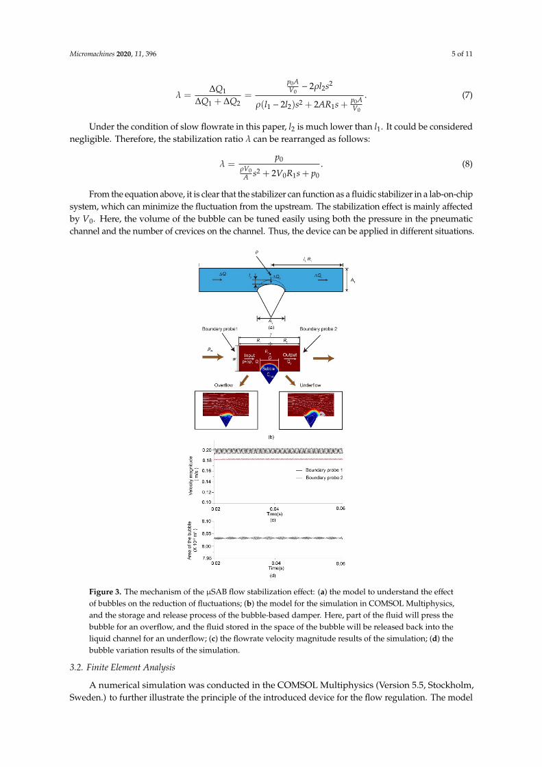
To further validate the working principle of the fluidic capacitor, another simulation in COMSOLMultiphysics was conducted using the model shown in Figure 3b. For more details, please refer to theSupplementary Materials Figure S2. According to Equation (7), the stabilization ratio λ is calculated byλ = ∆Q1/∆Q. In this study, the flowrate profile was obtained through simulation. Figure 4 demonstratesthat the fluctuation amplitude decreased by ~85% with the bubble-based fluidic stabilizer when thefrequency exceeded 1000 Hz.
Micromachines 2020, 11, x 6 of 11
Multiphysics, and the storage and release process of the bubble-based damper. Here, part of the fluid will press the bubble for an overflow, and the fluid stored in the space of the bubble will be released back into the liquid channel for an underflow; (c) the flowrate velocity magnitude results of the simulation; (d) the bubble variation results of the simulation.
3.2. Finite Element Analysis
A numerical simulation was conducted in the COMSOL Multiphysics (Version 5.5, Stockholm, Sweden.) to further illustrate the principle of the introduced device for the flow regulation. The model established for the calculation is illustrated in Figure 3b. The width of the channel (w) was 150 μm, and the length of the channel (l) was 300 μm. The diameter (D) of the bubble was 60 μm, and the driven pressure pin = 20 + 10sin(106t) Pa. Two boundary probes were added to the inlet and outlet to obtain the velocity magnitude. Probe 1 stands for the inlet, while Probe 2 stands for the outlet. The two-phase flow was simulated using the level-set method.
When in the steady state, all the fluid flowing into the stabilizer will flow along the main channel to the outlet. Part of the fluid will press the bubble for an overflow, and the fluid stored in the space of the bubble will be released back into the liquid channel for an underflow, as shown in Figure 3b. Figure 3c demonstrates the flowrate velocity magnitude results at the inlet and outlet. Through the depicted curve, the input fluctuation is effectively surpassed. Figure 3d shows the variation of the bubble size. It is shown that the bubble size changes with the input flowrate, leading to a relatively stable flowrate at the output. Thus, the bubble-based fluidic stabilizer can function as a fluidic stabilizer similar to an electric filter. For more details, please refer to the Supplementary Materials Figure S1.
To further validate the working principle of the fluidic capacitor, another simulation in COMSOL Multiphysics was conducted using the model shown in Figure 3b. For more details, please refer to the Supplementary Materials Figure S2. According to Equation (7), the stabilization ratio λ is calculated by λ = ΔQ1/ΔQ. In this study, the flowrate profile was obtained through simulation. Figure 4 demonstrates that the fluctuation amplitude decreased by ~85% with the bubble-based fluidic stabilizer when the frequency exceeded 1000 Hz.
The relationship of the stabilization ration λ and fluctuation frequency is shown in Figure 4. The stabilization ratio decreased as frequency increased, which seemingly infers the filtering effect of the fluidic stabilizer.
Figure 4. Frequency response of the bubble-based fluidic stabilizer obtained through simulation via COMSOL Multiphysics.
4. Experiment and Verification
4.1. Chip Fabrication
To illustrate the flow-damping performance of the bubble-based stabilizer, several chips with bubble-generating crevices on the wall were firstly set up through the standard soft lithography
Figure 4. Frequency response of the bubble-based fluidic stabilizer obtained through simulation viaCOMSOL Multiphysics.
The relationship of the stabilization ration λ and fluctuation frequency is shown in Figure 4. Thestabilization ratio decreased as frequency increased, which seemingly infers the filtering effect of thefluidic stabilizer.
4. Experiment and Verification
4.1. Chip Fabrication
To illustrate the flow-damping performance of the bubble-based stabilizer, several chips withbubble-generating crevices on the wall were firstly set up through the standard soft lithography process.Firstly, the pattern of the microchannel with the crevices inserted on the channel wall was designed through acomputer-aided design (CAD) software program (AutoCAD 2019). The pattern created by the CAD wastransformed into photomasks on transparency films by high-resolution printing. The master that containedthe patterned relief structures on the surface was fabricated by lithography in photoresist SU-8 (Micro-ChemCorp, DURHAM, UK). The surface of the mold was salinized to make the surface hydrophobic. The PDMSbase (Dow Corning Sylgard 184 Elastomer kit, Midland, MI, USA) and curing agent were mixed in a 10:1mass ratio, stirring evenly. Subsequently, the bubbles in the mixture were passed through a vacuum dryingoven. Hereafter, the mixture was poured on the mold and degassed and cured for two hours in an oven witha temperature of 60 ◦C. In this way, the microchannel with the crevice structures was formed at the sametime. After curing, the PDMS stamp was separated from the master, then cut and punched. The PDMS and aglass slide were exposed to air plasma briefly and then bonded together, forming an entire microfluidic chip.
Micromachines 2020, 11, 396 7 of 11
4.2. Experiment
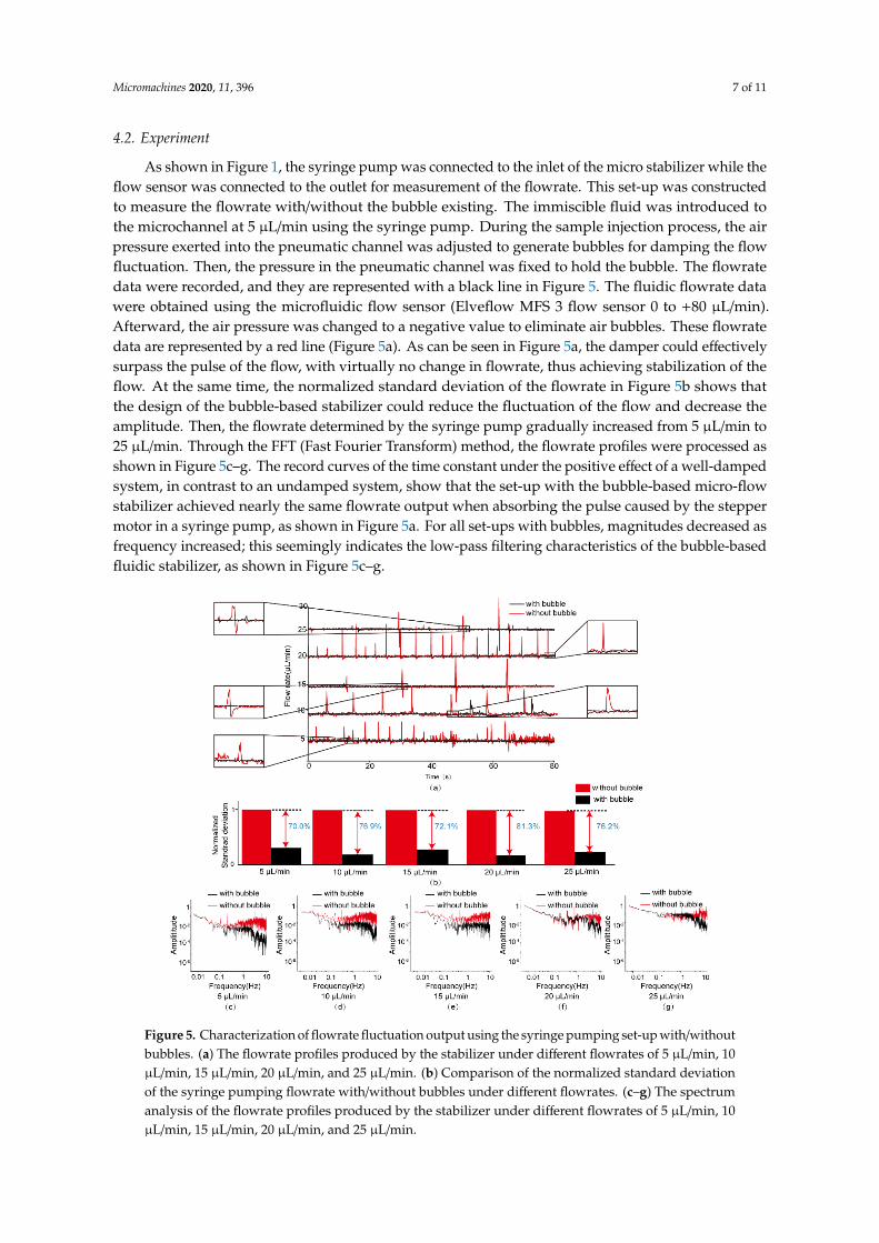
As shown in Figure 1, the syringe pump was connected to the inlet of the micro stabilizer while theflow sensor was connected to the outlet for measurement of the flowrate. This set-up was constructedto measure the flowrate with/without the bubble existing. The immiscible fluid was introduced tothe microchannel at 5 µL/min using the syringe pump. During the sample injection process, the airpressure exerted into the pneumatic channel was adjusted to generate bubbles for damping the flowfluctuation. Then, the pressure in the pneumatic channel was fixed to hold the bubble. The flowratedata were recorded, and they are represented with a black line in Figure 5. The fluidic flowrate datawere obtained using the microfluidic flow sensor (Elveflow MFS 3 flow sensor 0 to +80 µL/min).Afterward, the air pressure was changed to a negative value to eliminate air bubbles. These flowratedata are represented by a red line (Figure 5a). As can be seen in Figure 5a, the damper could effectivelysurpass the pulse of the flow, with virtually no change in flowrate, thus achieving stabilization of theflow. At the same time, the normalized standard deviation of the flowrate in Figure 5b shows thatthe design of the bubble-based stabilizer could reduce the fluctuation of the flow and decrease theamplitude. Then, the flowrate determined by the syringe pump gradually increased from 5 µL/min to25 µL/min. Through the FFT (Fast Fourier Transform) method, the flowrate profiles were processed asshown in Figure 5c–g. The record curves of the time constant under the positive effect of a well-dampedsystem, in contrast to an undamped system, show that the set-up with the bubble-based micro-flowstabilizer achieved nearly the same flowrate output when absorbing the pulse caused by the steppermotor in a syringe pump, as shown in Figure 5a. For all set-ups with bubbles, magnitudes decreased asfrequency increased; this seemingly indicates the low-pass filtering characteristics of the bubble-basedfluidic stabilizer, as shown in Figure 5c–g.
Micromachines 2020, 11, x 8 of 11
Figure 5. Characterization of flowrate fluctuation output using the syringe pumping set-up with/without bubbles. (a) The flowrate profiles produced by the stabilizer under different flowrates of 5 μL/min, 10 μL/min, 15 μL/min, 20 μL/min, and 25 μL/min. (b) Comparison of the normalized standard deviation of the syringe pumping flowrate with/without bubbles under different flowrates. (c–g) The spectrum analysis of the flowrate profiles produced by the stabilizer under different flowrates of 5 μL/min, 10 μL/min, 15 μL/min, 20 μL/min, and 25 μL/min.
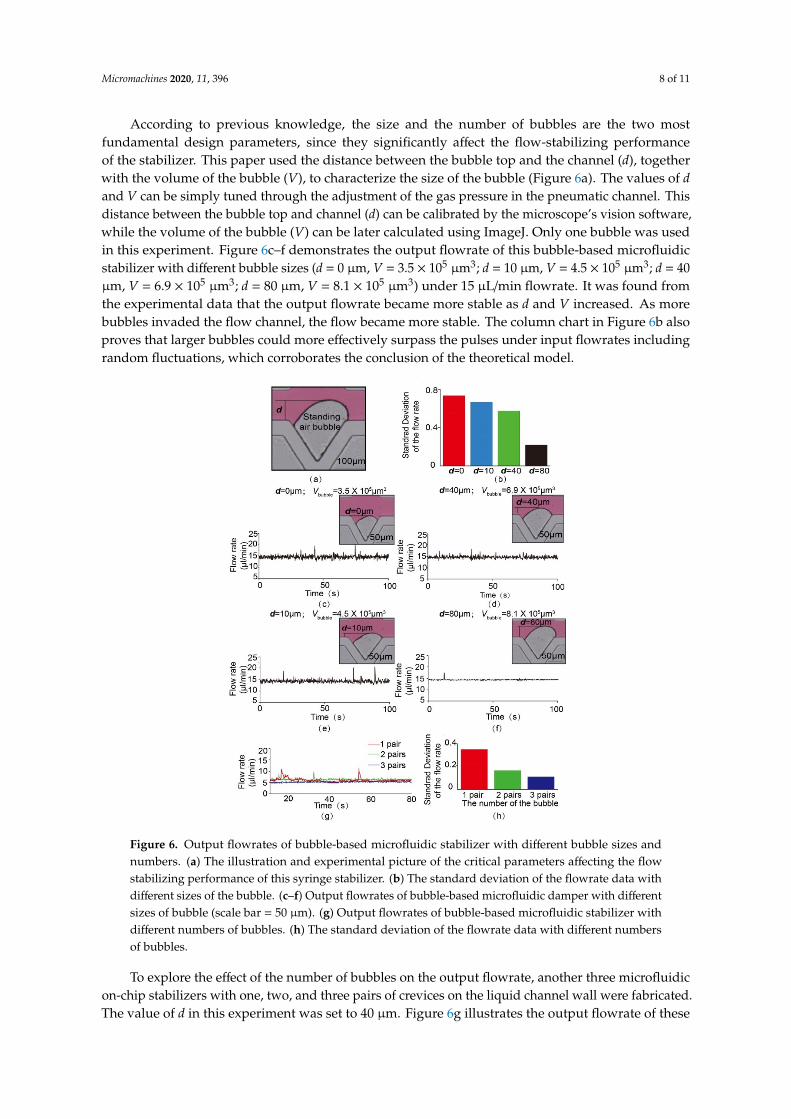
According to previous knowledge, the size and the number of bubbles are the two most fundamental design parameters, since they significantly affect the flow-stabilizing performance of the stabilizer. This paper used the distance between the bubble top and the channel (d), together with the volume of the bubble (V), to characterize the size of the bubble (Figure 6a). The values of d and V can be simply tuned through the adjustment of the gas pressure in the pneumatic channel. This distance between the bubble top and channel (d) can be calibrated by the microscope's vision software, while the volume of the bubble (V) can be later calculated using ImageJ. Only one bubble was used in this experiment. Figure 6c–f demonstrates the output flowrate of this bubble-based microfluidic stabilizer with different bubble sizes (d = 0 μm, V = 3.5 × 105 μm3; d = 10 μm, V = 4.5 × 105 μm3; d = 40 μm, V = 6.9 × 105 μm3; d = 80 μm, V = 8.1 × 105 μm3) under 15 μL/min flowrate. It was found from the experimental data that the output flowrate became more stable as d and V increased. As more bubbles invaded the flow channel, the flow became more stable. The column chart in Figure 6b also proves that larger bubbles could more effectively surpass the pulses under input flowrates including random fluctuations, which corroborates the conclusion of the theoretical model.
To explore the effect of the number of bubbles on the output flowrate, another three microfluidic on-chip stabilizers with one, two, and three pairs of crevices on the liquid channel wall were fabricated. The value of d in this experiment was set to 40 μm. Figure 6g illustrates the output flowrate of these three stabilization systems under the flowrate of 5 μL/min. Both the record curves of the flowrate in Figure 6g and the column chart in Figure 6h show that the increase in the number of bubbles could more effectively filter out the fluctuations and pulse, resulting in a more stable flow.
Figure 5. Characterization of flowrate fluctuation output using the syringe pumping set-up with/withoutbubbles. (a) The flowrate profiles produced by the stabilizer under different flowrates of 5 µL/min, 10µL/min, 15 µL/min, 20 µL/min, and 25 µL/min. (b) Comparison of the normalized standard deviationof the syringe pumping flowrate with/without bubbles under different flowrates. (c–g) The spectrumanalysis of the flowrate profiles produced by the stabilizer under different flowrates of 5 µL/min, 10µL/min, 15 µL/min, 20 µL/min, and 25 µL/min.
Micromachines 2020, 11, 396 8 of 11
According to previous knowledge, the size and the number of bubbles are the two mostfundamental design parameters, since they significantly affect the flow-stabilizing performanceof the stabilizer. This paper used the distance between the bubble top and the channel (d), togetherwith the volume of the bubble (V), to characterize the size of the bubble (Figure 6a). The values of dand V can be simply tuned through the adjustment of the gas pressure in the pneumatic channel. Thisdistance between the bubble top and channel (d) can be calibrated by the microscope’s vision software,while the volume of the bubble (V) can be later calculated using ImageJ. Only one bubble was usedin this experiment. Figure 6c–f demonstrates the output flowrate of this bubble-based microfluidicstabilizer with different bubble sizes (d = 0 µm, V = 3.5 × 105 µm3; d = 10 µm, V = 4.5 × 105 µm3; d = 40µm, V = 6.9 × 105 µm3; d = 80 µm, V = 8.1 × 105 µm3) under 15 µL/min flowrate. It was found fromthe experimental data that the output flowrate became more stable as d and V increased. As morebubbles invaded the flow channel, the flow became more stable. The column chart in Figure 6b alsoproves that larger bubbles could more effectively surpass the pulses under input flowrates includingrandom fluctuations, which corroborates the conclusion of the theoretical model.Micromachines 2020, 11, x 9 of 11
Figure 6. Output flowrates of bubble-based microfluidic stabilizer with different bubble sizes and numbers. (a) The illustration and experimental picture of the critical parameters affecting the flow stabilizing performance of this syringe stabilizer. (b) The standard deviation of the flowrate data with different sizes of the bubble. (c–f) Output flowrates of bubble-based microfluidic damper with different sizes of bubble (scale bar = 50 μm). (g) Output flowrates of bubble-based microfluidic stabilizer with different numbers of bubbles. (h) The standard deviation of the flowrate data with different numbers of bubbles.
To illustrate the potential practicality of the system in this paper, we designed a portable microfluidic system integrated with a bubble-based fluidic stabilizer for smooth flowrate delivery in the downstream. The bubble-based fluidic stabilization was realized using cost-efficient and available tools. Generally, the easily assessible fluidic stabilization cost will not exceed $100 United States dollars (USD), while a precise pressure-driven pump can cost up to $1000 USD. For more details, please refer to the Supplementary Materials Figure S3.
5. Conclusion
In this paper, a cost-efficient and easy-to-fabricate fluidic stabilization was achieved via a controllable micro standing air bubble. The standing air bubble generation and variation mechanisms were briefly introduced. According to Euler’s equation, we illustrated the theoretical model behind the fluidic stabilization by considering the bubble as a mass-spring system. The relationship between the stabilization effect and several key parameters, such as the size of the bubble, was also demonstrated through the theoretical model. The flexible gas–liquid interface embedded in the microchannel functions as a hydraulic capacitor, compared to a circuit network. The microfluidic network can be regarded as an electrical filter.
The standard deviation of fluctuations was reduced to 24.3% by the microfluidic stabilizer. The experimental results illustrated that the size and the number of bubbles employed in the system had a direct and significant influence on the output flowrate. Furthermore, potential applications were
Figure 6. Output flowrates of bubble-based microfluidic stabilizer with different bubble sizes andnumbers. (a) The illustration and experimental picture of the critical parameters affecting the flowstabilizing performance of this syringe stabilizer. (b) The standard deviation of the flowrate data withdifferent sizes of the bubble. (c–f) Output flowrates of bubble-based microfluidic damper with differentsizes of bubble (scale bar = 50 µm). (g) Output flowrates of bubble-based microfluidic stabilizer withdifferent numbers of bubbles. (h) The standard deviation of the flowrate data with different numbersof bubbles.
To explore the effect of the number of bubbles on the output flowrate, another three microfluidicon-chip stabilizers with one, two, and three pairs of crevices on the liquid channel wall were fabricated.The value of d in this experiment was set to 40 µm. Figure 6g illustrates the output flowrate of these
Micromachines 2020, 11, 396 9 of 11
three stabilization systems under the flowrate of 5 µL/min. Both the record curves of the flowrate inFigure 6g and the column chart in Figure 6h show that the increase in the number of bubbles couldmore effectively filter out the fluctuations and pulse, resulting in a more stable flow.
To illustrate the potential practicality of the system in this paper, we designed a portablemicrofluidic system integrated with a bubble-based fluidic stabilizer for smooth flowrate delivery inthe downstream. The bubble-based fluidic stabilization was realized using cost-efficient and availabletools. Generally, the easily assessible fluidic stabilization cost will not exceed $100 United States dollars(USD), while a precise pressure-driven pump can cost up to $1000 USD. For more details, please referto the Supplementary Materials Figure S3.
5. Conclusion
In this paper, a cost-efficient and easy-to-fabricate fluidic stabilization was achieved via acontrollable micro standing air bubble. The standing air bubble generation and variation mechanismswere briefly introduced. According to Euler’s equation, we illustrated the theoretical model behind thefluidic stabilization by considering the bubble as a mass-spring system. The relationship between thestabilization effect and several key parameters, such as the size of the bubble, was also demonstratedthrough the theoretical model. The flexible gas–liquid interface embedded in the microchannelfunctions as a hydraulic capacitor, compared to a circuit network. The microfluidic network can beregarded as an electrical filter.
The standard deviation of fluctuations was reduced to 24.3% by the microfluidic stabilizer. Theexperimental results illustrated that the size and the number of bubbles employed in the systemhad a direct and significant influence on the output flowrate. Furthermore, potential applicationswere introduced in this report. With a portable and low-cost damping set-up, a smooth flowrate wasgenerated successfully. For more details, please refer to the Supplementary Materials Figure S3. Thismicrofluidic stabilizer is suitable for different applications, such as hydrodynamic focusing, dropletgeneration, drug delivery, and particle synthesis.
Supplementary Materials: The following are available online at http://www.mdpi.com/2072-666X/11/4/396/s1,Figure S1: Schematic and a circuit representation of microfluidic systems driven by a syringe pump, Figure S2: Theresult from the Comsol simulation, Figure S3: Application of the microfluidic stabilizer in the portable microfluidicsystem for stable flow-rate delivery.
Author Contributions: Conceptualization, Y.Z. and J.L.; methodology, Y.Z. and J.L.; validation, Y.Z., J.Y., and T.Z.;formal analysis, Y.Z.; data curation, Y.Z. and J.Y.; writing—original draft preparation, Y.Z.; writing—review andediting, Y.Z. and J.L.; supervision, S.G., S.L., and T.L. All authors read and agreed to the published version ofthe manuscript.
Funding: This research was funded by the National Natural Science Foundation of China (NSFC) (Grant Nos.51605136 and 51505123), the China Postdoctoral Science Foundation (No. 2016M600180), and the Natural ScienceFoundation of Hebei Province (Nos. E2017202248 and E2015202194).
Conflicts of Interest: The authors declare no conflicts of interest.
References
1. Whitesides, G.M. The origins and the future of microfluidics. Nature 2006, 442, 368–373. [CrossRef]2. Kim, K.; Guo, J.; Liang, Z.; Fan, D. Artificial Micro/Nanomachines for Bioapplications: Biochemical Delivery
and Diagnostic Sensing. Adv. Funct. Mater. 2018, 28, 1705867. [CrossRef]3. Ng, E.; Chen, K.; Hang, A.; Syed, A.; Zhang, J.X. Multi-Dimensional Nanostructures for Microfluidic
Screening of Biomarkers: From Molecular Separation to Cancer Cell Detection. Ann. Biomed. Eng. 2016, 44,847–862. [CrossRef] [PubMed]
4. Tusan, C.G.; Man, Y.H.; Zarkoob, H.; Johnston, D.A.; Andriotis, O.G.; Thurner, P.J.; Yang, S.; Sander, E.A.;Gentleman, E.; Sengers, B.G.; et al. Collective Cell Behavior in Mechanosensing of Substrate Thickness.Biophys. J. 2018, 114, 2743–2755. [CrossRef]
5. Colace, T.V.; Tormoen, G.W.; McCarty, O.J.; Diamond, S.L. Microfluidics and coagulation biology. Annu. Rev.Biomed. Eng. 2013, 15, 283–303. [CrossRef]
Micromachines 2020, 11, 396 10 of 11
6. Atajanov, A.; Zhbanov, A.; Yang, S. Sorting and manipulation of biological cells and the prospects for usingoptical forces. Micro Nano Syst. Lett. 2018, 6, 2. [CrossRef]
7. Luo, T.; Fan, L.; Zhu, R.; Sun, D. Microfluidic Single-Cell Manipulation and Analysis: Methods andApplications. Micromachines 2019, 10, 104. [CrossRef]
8. Thameem, R.; Rallabandi, B.; Hilgenfeldt, S. Particle migration and sorting in microbubble streaming flows.Biomicrofluidics 2016, 10, 014124. [CrossRef]
9. Raj, A.; Sen, A.K. Microfluidic Sensors for Mechanophenotyping of Biological Cells. In Environmental,Chemical and Medical Sensors. Energy, Environment, and Sustainability; Springer: Singapore, 2018. [CrossRef]
10. Reddy, B.; Salm, E.; Bashir, R. Electrical Chips for Biological Point-of-Care Detection. Annu. Rev. Biomed. Eng.2016, 18, 329–355. [CrossRef]
11. Ma, Y.-H.V.; Middleton, K.; You, L.; Sun, Y. A review of microfluidic approaches for investigating cancerextravasation during metastasis. Microsyst. Nanoeng. 2018, 4, 17104. [CrossRef]
12. Sanjay, S.T.; Zhou, W.; Dou, M.; Tavakoli, H.; Ma, L.; Xu, F.; Li, X. Recent advances of controlled drug deliveryusing microfluidic platforms. Adv. Drug Deliv. Rev. 2018, 128, 3–28. [CrossRef]
13. Chapman, C.A.R.; Cuttaz, E.A.; Goding, J.A.; Green, R.A. Actively controlled local drug delivery usingconductive polymer-based devices. Appl. Phys. Lett. 2020, 116, 010501. [CrossRef]
14. Kumar, P.; Gandhi, P.S.; Majumder, M. Optimal morphometric factors responsible for enhanced gas exchangein fish gills. arXiv 2018, arXiv:2805.07744.
15. Kumar, P.; Gandhi, P.S.; Majumder, M. Enhanced capillary pumping through evaporation assistedleaf-mimicking micropumps. arXiv 2018, arXiv:1807.11464.
16. Qu, Y.; Zhou, J.; Wu, W. Theoretical and Experimental Research on Bubble Actuated Micro-Pumps.Micromachines 2018, 9, 225. [CrossRef] [PubMed]
17. Khoshmanesh, K.; Almansouri, A.; Albloushi, H.; Yi, P.; Soffe, R.; Kalantar-zadeh, K. A multi-functionalbubble-based microfluidic system. Sci. Rep. 2015, 5, 9942. [CrossRef] [PubMed]
18. Raj, A.; Suthanthiraraj, P.P.; Sen, A.K. Pressure-driven flow through PDMS-based flexible microchannels andtheir applications in microfluidics. Microfluid. Nanofluid. 2018, 22, 128. [CrossRef]
19. Uhlig, S.; Gaudet, M.; Langa, S.; Schimmanz, K.; Conrad, H.; Kaiser, B.; Schenk, H. Electrostatically DrivenIn-Plane Silicon Micropump for Modular Configuration. Micromachines 2018, 9, 190. [CrossRef]
20. Leu, T.-S.; Kao, R.-H. Design and operation of a bio-inspired micropump based on blood-sucking mechanismof mosquitoes. Mod. Phys. Lett. B 2018, 32, 1840027. [CrossRef]
21. Jiao, Z.; Zhao, J.; Chao, Z.; You, Z.; Zhao, J. An air-chamber-based microfluidic stabilizer for attenuatingsyringe-pump-induced fluctuations. Microfluid. Nanofluid. 2019, 23, 26. [CrossRef]
22. Zeng, W.; Jacobi, I.; Beck, D.J.; Li, S.; Stone, H.A. Characterization of syringe-pump-driven induced pressurefluctuations in elastic microchannels. Lab Chip 2014, 15, 1110–1115. [CrossRef] [PubMed]
23. Guo, P.; Wang, Z.; Heng, L.; Zhang, Y.; Wang, X.; Jiang, L. Magnetocontrollable Droplet and BubbleManipulation on a Stable Amphibious Slippery Gel Surface. Adv. Funct. Mater. 2019, 29, 1808717. [CrossRef]
24. Yang, B.; Lin, Q. A Compliance-Based Microflow Stabilizer. J. Microelectromech. Syst. 2009, 18, 539–546.[CrossRef]
25. Iyer, V.; Raj, A.; Annabattula, R.K.; Sen, A.K. Experimental and numerical studies of a microfluidic devicewith compliant chambers for flow stabilization. J. Micromech. Microeng. 2015, 25, 075003. [CrossRef]
26. Kalantarifard, A.; Alizadeh Haghighi, E.; Elbuken, C. Damping hydrodynamic fluctuations in microfluidicsystems. Chem. Eng. Sci. 2018, 178, 238–247. [CrossRef]
27. Lee, J.; Rahman, F.; Laoui, T.; Karnik, R. Bubble-induced damping in displacement-driven microfluidic flows.Phys. Rev. E 2012, 86, 026301. [CrossRef]
28. Kang, Y.J.; Yang, S. Fluidic low pass filter for hydrodynamic flow stabilization in microfluidic environments.Lab Chip 2012, 12, 1881–1889. [CrossRef]
29. Xiang, N.; Han, Y.; Jia, Y.; Shi, Z.; Yi, H.; Ni, Z. Flow stabilizer on a syringe tip for hand-powered microfluidicsample injection. Lab Chip 2019, 19, 214–222. [CrossRef]
30. Kilani, M.; Khasawneh, H.; Badran, A.; Awidi, A. Further development on a gentle electromagnetic pumpfor fluids with stress-sensitive microparticles. Sens. Actuators A Phys. 2016, 247, 440–447. [CrossRef]
31. Casals-Terré, J.; Duch, M.; Plaza, J.A.; Esteve, J.; Pérez-Castillejos, R.; Vallés, E.; Gómez, E. Design andcharacterization of a magnetic digital flow regulator. Sens. Actuators A Phys. 2010, 162, 107–115. [CrossRef]
Micromachines 2020, 11, 396 11 of 11
32. Liu, J.; Li, B.; Zhu, T.; Zhou, Y.; Li, S.; Guo, S.; Li, T.J.B. Tunable microfluidic standing air bubbles and itsapplication in acoustic microstreaming. Biomicrofluidics 2019, 13, 034114. [CrossRef] [PubMed]
33. Atchley, A.A.; Prosperetti, A. The crevice model of bubble nucleation. J. Acoust. Soc. Am. 1989, 86, 1065–1084.[CrossRef]
34. Jones, S.F.; Evans, G.M.; Galvin, K.P. Bubble nucleation from gas cavities—A review. Adv. Colloid Interface Sci.1999, 80, 27–50. [CrossRef]
35. Liu, J.; Li, S.; Mitra, D. Multiphysical phenomenon of air bubble growth in polydimethylsiloxane channelcorners under microfluidic negative pressure-driven flow. Int. J. Heat Mass Transf. 2015, 91, 611–618.[CrossRef]
36. Haubert, K.; Drier, T.; Beebe, D. PDMS bonding by means of a portable, low-cost corona system. Lab Chip2006, 6, 1548–1549. [CrossRef]
© 2020 by the authors. Licensee MDPI, Basel, Switzerland. This article is an open accessarticle distributed under the terms and conditions of the Creative Commons Attribution(CC BY) license (http://creativecommons.org/licenses/by/4.0/).