Embed Size (px)
Citation preview

Line Thermal Printer
STAR Line Mode Command
Specifications
Rev 1.12
Star Micronics Co., Ltd. Special Products Division
Table of Contents 1. INTERFACE CONFIGURATION.........................................................................................................................1-1
1.1. RS-232 Serial Interface ..............................................................................................................................1-1 1.1.1. Specifications (Conforming to RS-232) ..............................................................................................1-1 1.1.2. Signal array and explanations according to interface connector pin ..................................................1-1 1.1.3. Communication Protocol ....................................................................................................................1-2
1.2. Parallel Interfaces (Amphenol 36 pins).......................................................................................................1-4 1.2.1. Specifications (Conforming to IEEE1284) ..........................................................................................1-4 1.2.2. Signal array and explanations according to interface connector pin ..................................................1-4 1.2.3. Signal Output Timing..........................................................................................................................1-5 1.2.4. Status Specification............................................................................................................................1-5
1.3. USB Interface.............................................................................................................................................1-6 1.4. Ethernet Interface.......................................................................................................................................1-6 1.5. Wireless LAN Interface...............................................................................................................................1-6 1.6. Powered USB Interface..............................................................................................................................1-6
2. COMMAND FUNCTION LIST.............................................................................................................................2-1 3. COMMAND DETAILS.........................................................................................................................................3-1
3.1. Explanation of Terms..................................................................................................................................3-1 3.2. Exception Processing.................................................................................................................................3-2 3.3. Standard Command Details .......................................................................................................................3-3
3.3.1. Font style and Character Set .............................................................................................................3-3 3.3.2. Character Expansion Settings..........................................................................................................3-12 3.3.3. Print Mode .......................................................................................................................................3-16 3.3.4. Line Spacing ....................................................................................................................................3-20 3.3.5. Page Control Commands.................................................................................................................3-23 3.3.6. Horizontal Direction Printing Position...............................................................................................3-27 3.3.7. Download.........................................................................................................................................3-32 3.3.8. Bit Image Graphics ..........................................................................................................................3-34 3.3.9. Logo.................................................................................................................................................3-38 3.3.10. Bar Code..........................................................................................................................................3-42 3.3.11. Cutter Control...................................................................................................................................3-44 3.3.12. External Device Drive ......................................................................................................................3-45 3.3.13. Print Settings....................................................................................................................................3-51 3.3.14. Status...............................................................................................................................................3-53 3.3.15. Kanji characters ...............................................................................................................................3-59 3.3.16. Others ..............................................................................................................................................3-63
3.4. Raster Graphics Command Details ..........................................................................................................3-68 3.5. Black Mark Related Command Details.....................................................................................................3-87 3.6. USB Related Command Details ...............................................................................................................3-91 3.7. 2 Color Printing Command Details ...........................................................................................................3-92 3.8. Presenter Related Command Details .....................................................................................................3-101 3.9. Mark Command Details..........................................................................................................................3-106 3.10. AUTO LOGO Function Command Details .............................................................................................. 3-111 3.11. Two-dimensional Bar Code PDF417 Command Details.........................................................................3-120 3.12. Details of the Print Starting Trigger Control Command...........................................................................3-125 3.13. Two-Dimensional Bar Code QR Code Command Details ......................................................................3-126 3.14. Page Function Command Details...........................................................................................................3-133 3.15. Reduced Printing Function Command Details........................................................................................3-134 3.16. Page Mode Command Details................................................................................................................3-135 3.17. Text Search Command Details ...............................................................................................................3-142 3.18. Audio Command Details.........................................................................................................................3-147
4. CHARACTER CODE TABLES............................................................................................................................4-1 5. APPENDIX .........................................................................................................................................................5-1
5.1. Appendix 1: Bar Code Specification Details ...............................................................................................5-1 5.1.1. Code 39 .............................................................................................................................................5-1
――――――――――――――――――――――――――――――――――――――――――――――――――――――――――――――――――――――――――――― STAR Line Mode Command Specifications 1
5.1.2. Interleaved 2 of 5 ...............................................................................................................................5-1 5.1.3. JAN/EAN/UPC ...................................................................................................................................5-2 5.1.4. Code 128 ...........................................................................................................................................5-3 5.1.5. Code 93 .............................................................................................................................................5-5 5.1.6. NW7 (CODERBAR) ...........................................................................................................................5-5
5.2. Appendix 2: Status Specifications ..............................................................................................................5-6 5.2.1. ENQ Command Status.......................................................................................................................5-6 5.2.2. EOT Command Status .......................................................................................................................5-6 5.2.3. Automatic Status ................................................................................................................................5-7 5.2.4 Printer status transmission specification when using Ethernet I/F and Wireless LAN I/F.....................5-14
5.3. Appendix 3: Blank Code Page Configuration ...........................................................................................5-16 5.4. Appendix 7 Maximum Number of Input Characters for Each Version of QR Code...................................5-19 5.5. Appendix 8 TSP828L Cut Command Specifications.................................................................................5-23 5.6. Appendix 6 Explanation of Page Mode ....................................................................................................5-24
5-6-1. Overview..........................................................................................................................................5-24 5-6-2. Setting Values Using Each Command in Standard Mode and Page Mode ......................................5-24 5-6-3. Print Data Expansion to the Print Region.........................................................................................5-25
5.7. 5-7) Appendix 7 Explanation of Print Startup Control Starting Printing When Set to Page Units ..............5-27 6. SPECIAL APPENDIX COMMAND LIST FOR EACH MODEL IN EACH I/F........................................................6-1
6.1. RS-232C I/F ...............................................................................................................................................6-1 6.2. Parallel I/F • USB I/F (Ver2.0) • Powered USB I/F.....................................................................................6-6 6.3. USB I/F (Ver1.0) • Ethernet I/F (Silex Ver1.0)..........................................................................................6-12 6.4. Ethernet I/F / Wireless LAN I/F.................................................................................................................6-18 6.5. Wireless LAN I/F ......................................................................................................................................6-24
――――――――――――――――――――――――――――――――――――――――――――――――――――――――――――――――――――――――――――― STAR Line Mode Command Specifications 2
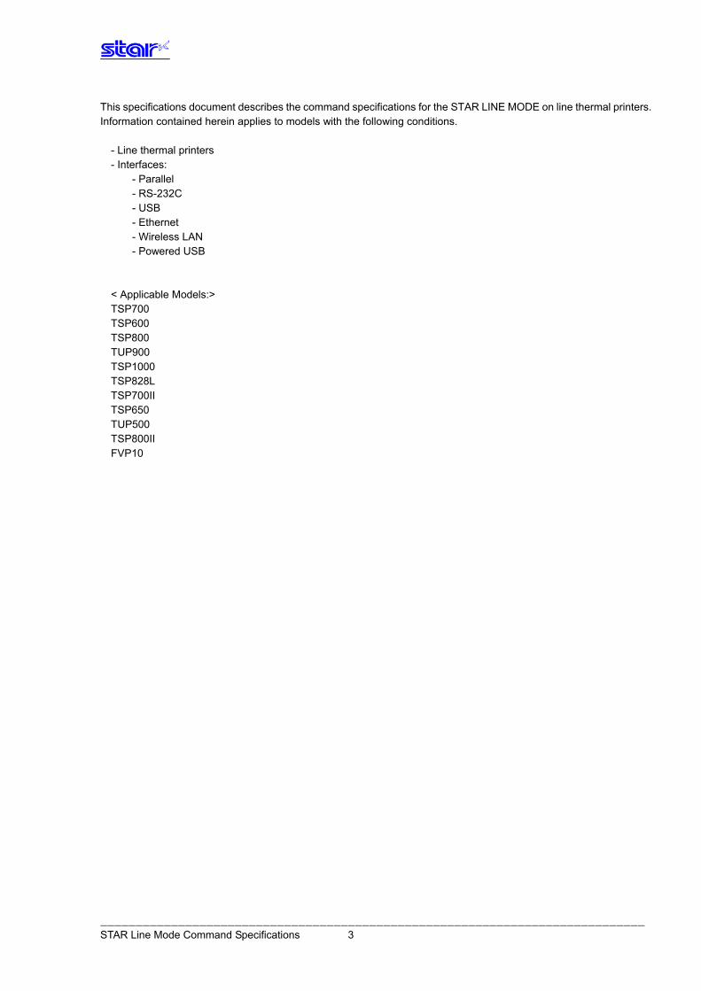
This specifications document describes the command specifications for the STAR LINE MODE on line thermal printers. Information contained herein applies to models with the following conditions.
- Line thermal printers - Interfaces:
- Parallel - RS-232C - USB - Ethernet - Wireless LAN - Powered USB
< Applicable Models:> TSP700 TSP600 TSP800 TUP900 TSP1000 TSP828L TSP700II TSP650 TUP500 TSP800II FVP10
――――――――――――――――――――――――――――――――――――――――――――――――――――――――――――――――――――――――――――― STAR Line Mode Command Specifications 3
1. INTERF ACE CONFIGURATION
1.1. RS-232 Serial Interface
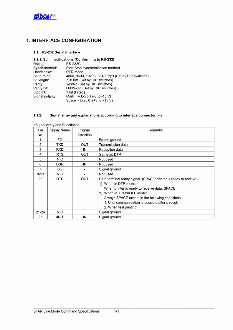
1.1.1. Sp ecifications (Conforming to RS-232) Rating: RS-232C Synch method: Start-Stop synchronization method Handshake: DTR mode Baud rates: 4800, 9600, 19200, 38400 bps (Set by DIP switches) Bit length: 7, 8 bits (Set by DIP switches) Parity: Yes/No (Set by DIP switches) Parity bit: Odd/even (Set by DIP switches) Stop bit: 1 bit (Fixed) Signal polarity: Mark = logic 1 (-3 to -15 V) Space = logic 0 (+3 to +15 V)
1.1.2. Signal array and explanations according to interface connector pin <Signal Array and Functions>
Pin No.
Signal Name Signal Direction
Remarks
1 FG - Frame ground 2 TXD OUT Transmission data 3 RXD IN Reception data 4 RTS OUT Same as DTR 5 N.C - Not used 6 DSR IN Not used 7 SG - Signal ground
8-19 N.C - Not used 20 DTR OUT Data terminal ready signal (SPACE: printer is ready to receive.)
1) When in DTR mode: When printer is ready to receive data: SPACE 2) When in XON/XOFF mode: Always SPACE except in the following conditions. 1. Until communication is possible after a reset. 2. When test printing
21-24 N.C Signal ground 25 /INIT IN Signal ground
――――――――――――――――――――――――――――――――――――――――――――――――――――――――――――――――――――――――――――― STAR Line Mode Command Specifications 1-1
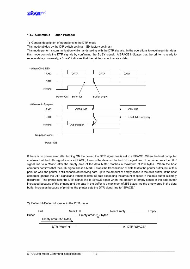
1.1.3. Communic ation Protocol 1) General description of operations in the DTR mode This mode abides by the DIP switch settings. (Ex-factory settings) This mode performs communication while handshaking with the DTR signals. In the operations to receive printer data, this mode controls the DTR signals by confirming the BUSY signal. A SPACE indicates that the printer is ready to receive data; conversely, a “mark” indicates that the printer cannot receive data.
<When ON-LINE> RXD DATA DATA DATA
If there is no printer error after turning ON the power, the DTR signal line is set to a SPACE. When the host computer confirms that the DTR signal line is a SPACE, it sends the data text to the RXD signal line. The printer sets the DTR signal line to a “Mark” after the empty area of the data buffer reaches a maximum of 256 bytes. When the host computer confirms that the DTR signal line is a Mark, it stops the transmission of data text to the printer buffer, but at this point as well, the printer is still capable of receiving data, up to the amount of empty space in the data buffer. If the host computer ignores the DTR signal and transmits data, all data exceeding the amount of space in the data buffer is simply discarded. The printer sets the DTR signal line to SPACE again when the amount of empty space in the data buffer increased because of the printing and the data in the buffer is a maximum of 256 bytes. As the empty area in the data buffer increases because of printing, the printer sets the DTR signal line to “SPACE.” 2) Buffer full/Buffer full cancel in the DTR mode
Full Near Full Near Empty Empty Buffer Empty area: 512 bytes
Empty area: 256 bytes DTR "Mark" DTR "SPACE"
DTR Printing
Power ON Buffer full Buffer empty <When out of paper> RXD OFF-LINE ON-LINE DTR ON-LINE Recovery Printing Out of paper
No paper signal Power ON
――――――――――――――――――――――――――――――――――――――――――――――――――――――――――――――――――――――――――――― STAR Line Mode Command Specifications 1-2
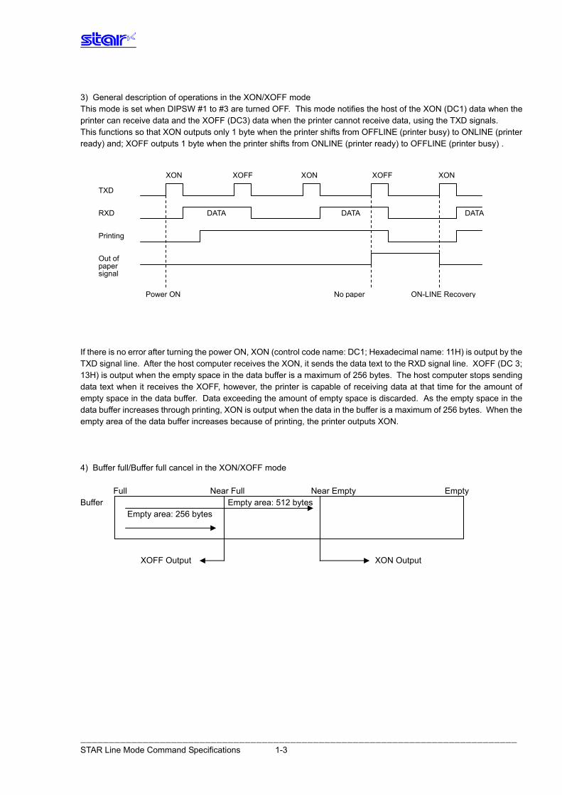
3) General description of operations in the XON/XOFF mode This mode is set when DIPSW #1 to #3 are turned OFF. This mode notifies the host of the XON (DC1) data when the printer can receive data and the XOFF (DC3) data when the printer cannot receive data, using the TXD signals. This functions so that XON outputs only 1 byte when the printer shifts from OFFLINE (printer busy) to ONLINE (printer ready) and; XOFF outputs 1 byte when the printer shifts from ONLINE (printer ready) to OFFLINE (printer busy) .
XON XOFF XON XOFF XON
If there is no error after turning the power ON, XON (control code name: DC1; Hexadecimal name: 11H) is output by the TXD signal line. After the host computer receives the XON, it sends the data text to the RXD signal line. XOFF (DC 3; 13H) is output when the empty space in the data buffer is a maximum of 256 bytes. The host computer stops sending data text when it receives the XOFF, however, the printer is capable of receiving data at that time for the amount of empty space in the data buffer. Data exceeding the amount of empty space is discarded. As the empty space in the data buffer increases through printing, XON is output when the data in the buffer is a maximum of 256 bytes. When the empty area of the data buffer increases because of printing, the printer outputs XON. 4) Buffer full/Buffer full cancel in the XON/XOFF mode
Full Near Full Near Empty Empty
Buffer Empty area: 512 bytes Empty area: 256 bytes
XOFF Output XON Output
TXD RXD DATA DATA DATA Printing Out of paper signal
Power ON No paper ON-LINE Recovery
――――――――――――――――――――――――――――――――――――――――――――――――――――――――――――――――――――――――――――― STAR Line Mode Command Specifications 1-3
1.2. Parallel Interfaces (Amphenol 36 pins)
1.2.1. Specifications (Conforming to IEEE1284) Rating: Conforms to IEEE 1284 Mode: Compatibility Mode/Nibble Mode/Byte Mode Data transfer speed: 1000 to 6000 CPS Synch method: According to externally supplied strobe pulse Handshake: According to ACK and BUSY signals Logic level: Compatible to TTL
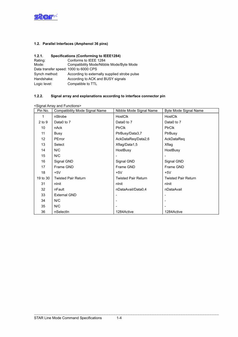
1.2.2. Signal array and explanations according to interface connector pin <Signal Array and Functions>
Pin No. Compatibility Mode Signal Name Nibble Mode Signal Name Byte Mode Signal Name HostClk HostClk nStrobe 1 Data0 to 7 Data0 to 7 Data0 to 7 2 to 9 PtrClk PtrClk nAck 10 PtrBusy PtrBusy/Data3,7 Busy 11 AckDataReq AckDataReq/Data2,6 PError 12 Xflag Xflag/Data1,5 Select 13 HostBusy HostBusy N/C 14 - - N/C 15 Signal GND Signal GND Signal GND 16 Frame GND Frame GND Frame GND 17 +5V +5V +5V 18 Twisted Pair Return Twisted Pair Return Twisted Pair Return 19 to 30 nInit nInit nInit 31 nDataAvail nDataAvail/Data0,4 nFault 32 - - External GND 33 - - N/C 34 - - N/C 35 1284Active 1284Active nSelectIn 36
――――――――――――――――――――――――――――――――――――――――――――――――――――――――――――――――――――――――――――― STAR Line Mode Command Specifications 1-4
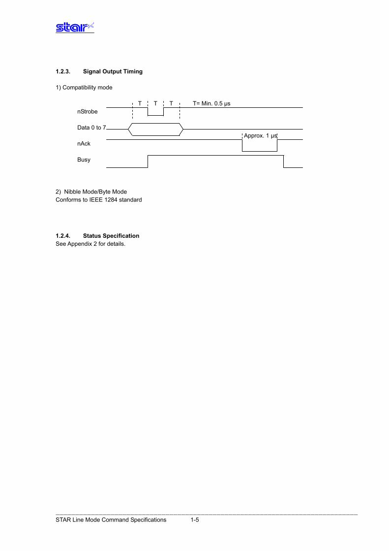
1.2.3. Signal Output Timing 1) Compatibility mode
T T T T= Min. 0.5 μs nStrobe
Data 0 to 7
Approx. 1 μs nAck
Busy
2) Nibble Mode/Byte Mode Conforms to IEEE 1284 standard
1.2.4. Status Specification See Appendix 2 for details.
――――――――――――――――――――――――――――――――――――――――――――――――――――――――――――――――――――――――――――― STAR Line Mode Command Specifications 1-5
1.3. USB Interface Specifications: Conforms to USB 2.0 Full Speed. Supports printer class and vendor class (Refer to each printer specifications manual for
selections.) Connector: Type B
1.4. Eth ernet Interface Specifications: Conforms to IEEE 802.3. Cable: 10BASE-T/10BASE-TX Connector: RJ45
1.5. W ireless LAN Interface Specifications: Conforms to IEEE 802.11b.
1.6. Powered USB Interface Specifications See the IFBD-BPU03 Specifications Manual Cable See the IFBD-BPU03 Specifications Manual Connector See the IFBD-BPU03 Specifications Manual
――――――――――――――――――――――――――――――――――――――――――――――――――――――――――――――――――――――――――――― STAR Line Mode Command Specifications 1-6
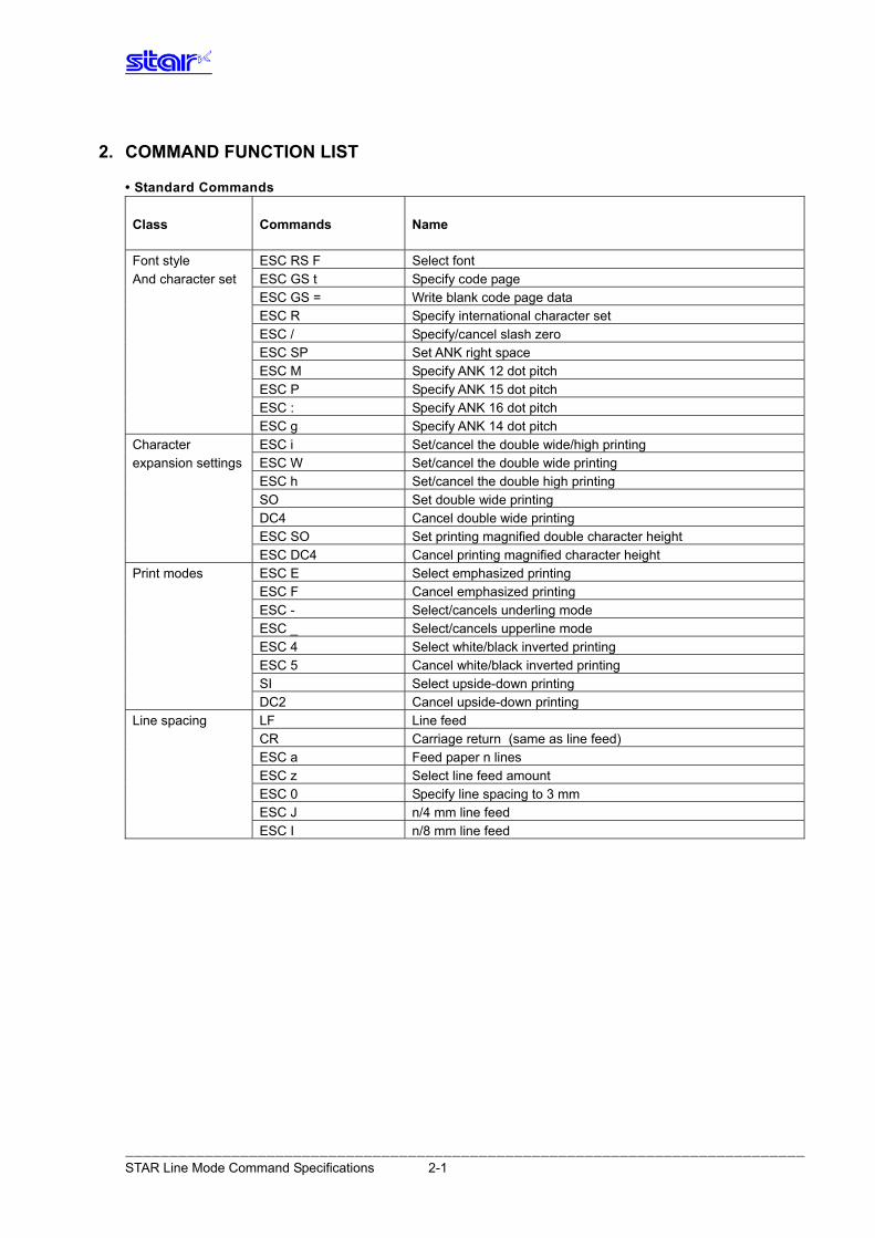
2. COMMAND FUNCTION LIST
• Standard Commands Commands Name Class
Font style ESC RS F Select font And character set ESC GS t Specify code page ESC GS = Write blank code page data
ESC R Specify international character set ESC / Specify/cancel slash zero ESC SP Set ANK right space ESC M Specify ANK 12 dot pitch ESC P Specify ANK 15 dot pitch ESC : Specify ANK 16 dot pitch ESC g Specify ANK 14 dot pitch Character ESC i Set/cancel the double wide/high printing expansion settings ESC W Set/cancel the double wide printing ESC h Set/cancel the double high printing SO Set double wide printing DC4 Cancel double wide printing ESC SO Set printing magnified double character height ESC DC4 Cancel printing magnified character height Print modes ESC E Select emphasized printing ESC F Cancel emphasized printing ESC - Select/cancels underling mode ESC _ Select/cancels upperline mode ESC 4 Select white/black inverted printing ESC 5 Cancel white/black inverted printing SI Select upside-down printing DC2 Cancel upside-down printing Line spacing LF Line feed CR Carriage return (same as line feed) ESC a Feed paper n lines ESC z Select line feed amount ESC 0 Specify line spacing to 3 mm ESC J n/4 mm line feed ESC I n/8 mm line feed
――――――――――――――――――――――――――――――――――――――――――――――――――――――――――――――――――――――――――――― STAR Line Mode Command Specifications 2-1
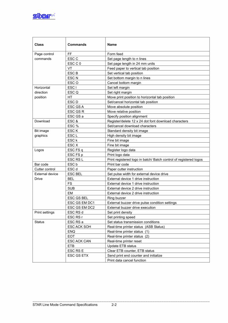
Commands Name Class
Page control FF Form feed commands ESC C Set page length to n lines ESC C 0 Set page length in 24 mm units VT Feed paper to vertical tab position
ESC B Set vertical tab position ESC N Set bottom margin to n lines ESC O Cancel bottom margin Horizontal ESC l Set left margin direction ESC Q Set right margin position HT Move print position to horizontal tab position ESC D Set/cancel horizontal tab position ESC GS A Move absolute position ESC GS R Move relative position ESC GS a Specify position alignment Download ESC & Register/delete 12 x 24 dot font download characters ESC % Set/cancel download characters Bit image ESC K Standard density bit image graphics ESC L High density bit image ESC k Fine bit image ESC X Fine bit image Logos ESC FS q Register logo data ESC FS p Print logo data ESC RS L Print registered logo in batch/ Batch control of registered logos Bar code ESC b Print bar code Cutter control ESC d Paper cutter instruction External device ESC BEL Set pulse width for external device drive Drive BEL External device 1 drive instruction FS External device 1 drive instruction SUB External device 2 drive instruction EM External device 2 drive instruction ESC GS BEL Ring buzzer ESC GS EM DC1 External buzzer drive pulse condition settings ESC GS EM DC2 External buzzer drive execution Print settings ESC RS d Set print density ESC RS r Set printing speed Status ESC RS a Set status transmission conditions ESC ACK SOH Real-time printer status (ASB Status) ENQ Real-time printer status (1) EOT Real-time printer status (2) ESC ACK CAN Real-time printer reset ETB Update ETB status ESC RS E Clear ETB counter, ETB status ESC GS ETX Send print end counter and initialize Print data cancel function
――――――――――――――――――――――――――――――――――――――――――――――――――――――――――――――――――――――――――――― STAR Line Mode Command Specifications 2-2
Commands Name Class
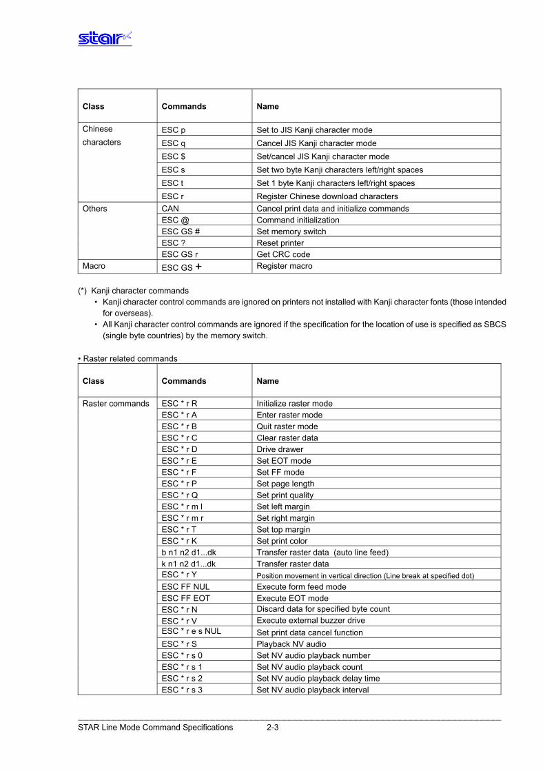
Chinese ESC p Set to JIS Kanji character mode characters ESC q Cancel JIS Kanji character mode ESC $ Set/cancel JIS Kanji character mode ESC s Set two byte Kanji characters left/right spaces ESC t Set 1 byte Kanji characters left/right spaces ESC r Register Chinese download characters Others CAN Cancel print data and initialize commands ESC @ Command initialization ESC GS # Set memory switch ESC ? Reset printer ESC GS r Get CRC code
ESC GS + Macro Register macro (*) Kanji character commands
• Kanji character control commands are ignored on printers not installed with Kanji character fonts (those intended for overseas).
• All Kanji character control commands are ignored if the specification for the location of use is specified as SBCS (single byte countries) by the memory switch.
• Raster related commands
Commands Name Class
Raster commands ESC * r R Initialize raster mode ESC * r A Enter raster mode ESC * r B Quit raster mode ESC * r C Clear raster data ESC * r D Drive drawer ESC * r E Set EOT mode ESC * r F Set FF mode ESC * r P Set page length ESC * r Q Set print quality ESC * r m l Set left margin ESC * r m r Set right margin ESC * r T Set top margin ESC * r K Set print color b n1 n2 d1...dk Transfer raster data (auto line feed) k n1 n2 d1...dk Transfer raster data
ESC * r Y Position movement in vertical direction (Line break at specified dot) ESC FF NUL Execute form feed mode ESC FF EOT Execute EOT mode
Discard data for specified byte count ESC * r N Execute external buzzer drive ESC * r V
ESC * r e s NUL Set print data cancel function ESC * r S Playback NV audio ESC * r s 0 Set NV audio playback number ESC * r s 1 Set NV audio playback count ESC * r s 2 Set NV audio playback delay time ESC * r s 3 Set NV audio playback interval
――――――――――――――――――――――――――――――――――――――――――――――――――――――――――――――――――――――――――――― STAR Line Mode Command Specifications 2-3
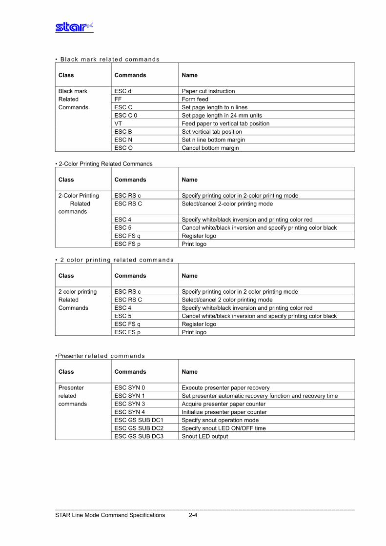
• B lack mark re la ted commands Commands Name Class
Black mark ESC d Paper cut instruction Related FF Form feed Commands ESC C Set page length to n lines ESC C 0 Set page length in 24 mm units VT Feed paper to vertical tab position ESC B Set vertical tab position ESC N Set n line bottom margin ESC O Cancel bottom margin
• 2-Color Printing Related Commands
Commands Name Class
2-Color Printing ESC RS c Specify printing color in 2-color printing mode
Related commands
ESC RS C Select/cancel 2-color printing mode
ESC 4 Specify white/black inversion and printing color red ESC 5 Cancel white/black inversion and specify printing color black ESC FS q Register logo ESC FS p Print logo
• 2 co lo r p r i n t i ng re l a ted commands
Commands Name Class
2 color printing ESC RS c Specify printing color in 2 color printing mode Related ESC RS C Select/cancel 2 color printing mode Commands ESC 4 Specify white/black inversion and printing color red ESC 5 Cancel white/black inversion and specify printing color black ESC FS q Register logo ESC FS p Print logo
•Presenter re l a ted comm ands
Commands Name Class
Presenter ESC SYN 0 Execute presenter paper recovery related ESC SYN 1 Set presenter automatic recovery function and recovery time commands ESC SYN 3 Acquire presenter paper counter ESC SYN 4 Initialize presenter paper counter ESC GS SUB DC1 Specify snout operation mode ESC GS SUB DC2 Specify snout LED ON/OFF time ESC GS SUB DC3 Snout LED output
――――――――――――――――――――――――――――――――――――――――――――――――――――――――――――――――――――――――――――― STAR Line Mode Command Specifications 2-4
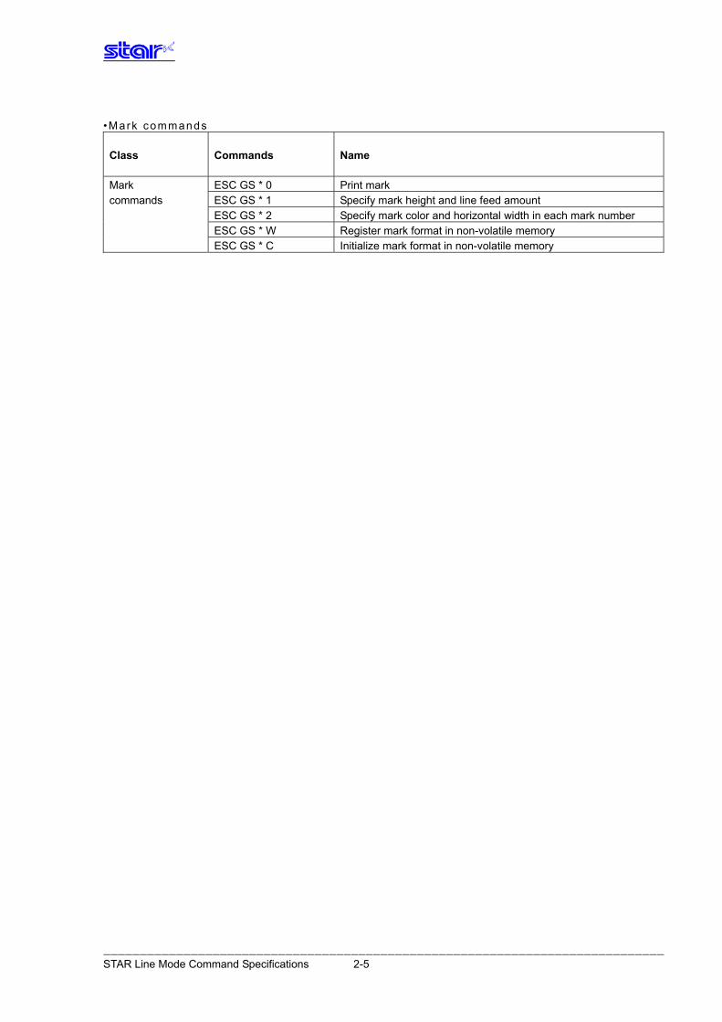
•Mark commands
Commands Name Class
Mark ESC GS * 0 Print mark commands ESC GS * 1 Specify mark height and line feed amount ESC GS * 2 Specify mark color and horizontal width in each mark number ESC GS * W Register mark format in non-volatile memory ESC GS * C Initialize mark format in non-volatile memory
――――――――――――――――――――――――――――――――――――――――――――――――――――――――――――――――――――――――――――― STAR Line Mode Command Specifications 2-5
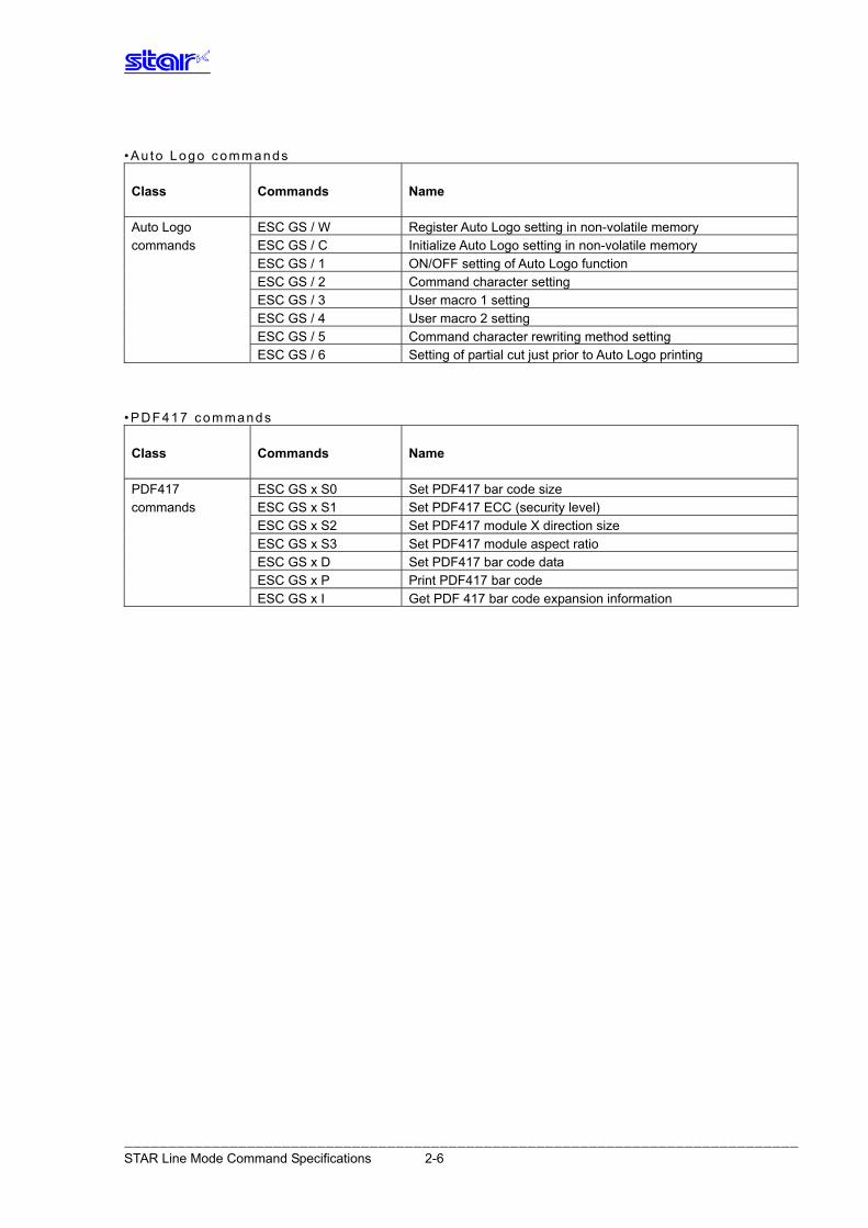
•Au to Logo commands
Commands Name Class
Auto Logo ESC GS / W Register Auto Logo setting in non-volatile memory commands ESC GS / C Initialize Auto Logo setting in non-volatile memory ESC GS / 1 ON/OFF setting of Auto Logo function ESC GS / 2 Command character setting ESC GS / 3 User macro 1 setting ESC GS / 4 User macro 2 setting ESC GS / 5 Command character rewriting method setting ESC GS / 6 Setting of partial cut just prior to Auto Logo printing
•PDF417 commands
Commands Name Class
PDF417 ESC GS x S0 Set PDF417 bar code size commands ESC GS x S1 Set PDF417 ECC (security level) ESC GS x S2 Set PDF417 module X direction size ESC GS x S3 Set PDF417 module aspect ratio ESC GS x D Set PDF417 bar code data ESC GS x P Print PDF417 bar code ESC GS x I Get PDF 417 bar code expansion information
――――――――――――――――――――――――――――――――――――――――――――――――――――――――――――――――――――――――――――― STAR Line Mode Command Specifications 2-6
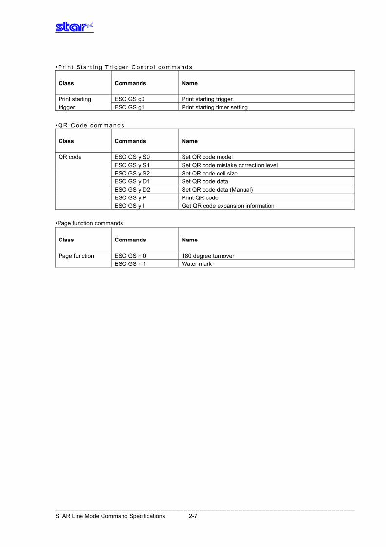
•P r i n t S ta r t i ng T r i gge r Con t ro l commands
Commands Name Class
Print starting ESC GS g0 Print starting trigger trigger ESC GS g1 Print starting timer setting
•QR Code commands
Commands Name Class
QR code ESC GS y S0 Set QR code model ESC GS y S1 Set QR code mistake correction level ESC GS y S2 Set QR code cell size ESC GS y D1 Set QR code data ESC GS y D2 Set QR code data (Manual) ESC GS y P Print QR code ESC GS y I Get QR code expansion information
•Page function commands
Commands Name Class
Page function ESC GS h 0 180 degree turnover ESC GS h 1 Water mark
――――――――――――――――――――――――――――――――――――――――――――――――――――――――――――――――――――――――――――― STAR Line Mode Command Specifications 2-7
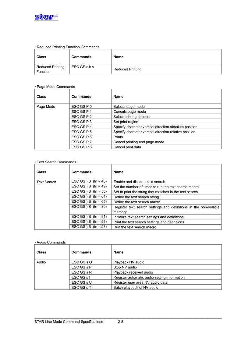
• Reduced Printing Function Commands
Class Commands Name
Reduced Printing Function
ESC GS c h v Reduced Printing
• Page Mode Commands
Class Commands Name
Page Mode ESC GS P 0 Selects page mode ESC GS P 1 Cancels page mode
ESC GS P 2 Select printing direction
ESC GS P 3 Set print region
ESC GS P 4 Specify character vertical direction absolute position
ESC GS P 5 Specify character vertical direction relative position
ESC GS P 6 Prints
ESC GS P 7 Cancel printing and page mode
ESC GS P 8 Cancel print data
• Text Search Commands
Class Commands Name
ESC GS ) B (fn = 48) Enable and disables text search Text Search ESC GS ) B (fn = 49) Set the number of times to run the text search macro
ESC GS ) B (fn = 50) Set to print the string that matches in the text search
ESC GS ) B (fn = 64) Define the text search string
ESC GS ) B (fn = 65) Define the text search macro
ESC GS ) B (fn = 80) Register text search settings and definitions in the non-volatile memory
ESC GS ) B (fn = 81) Initialize text search settings and definitions
ESC GS ) B (fn = 96) Print the text search settings and definitions
ESC GS ) B (fn = 97) Run the text search macro
• Audio Commands
Class Commands Name
Audio ESC GS s O Playback NV audio ESC GS s P Stop NV audio
ESC GS s R Playback received audio
ESC GS s I Register automatic audio setting information
ESC GS s U Register user area NV audio data
ESC GS s T Batch playback of NV audio
――――――――――――――――――――――――――――――――――――――――――――――――――――――――――――――――――――――――――――― STAR Line Mode Command Specifications 2-8
3. COMMAND DETAILS
3.1. Exp lanation of Terms • Reception buffer
The buffer for storing data (reception data) received from the host, as it is called the reception buffer. Reception data is temporarily stored in the reception buffer, then processed sequentially.
• Line buffer
The buffer for storing image data for printing is called the line buffer. • Line buffer full
The state in which the buffer has no more space available is called line buffer full. When the buffer is full in standard mode, data in the line buffer is printed and a line feed is performed when new print data is processed. This is the same as a Line Feed. When the line buffer is full in the page mode, the printer move the print position to the head of the next line then starts with the new print data.
• Top of line
The top of line is a state that satisfies the following conditions. - There is currently no print data in the line buffer. - The position is not specified with the horizontal direction position command.
• Printable region
This is the maximum printable area with the printer’s specifications. • Print region
This is the printing area specified by a command. (Print region ≤ printable region)
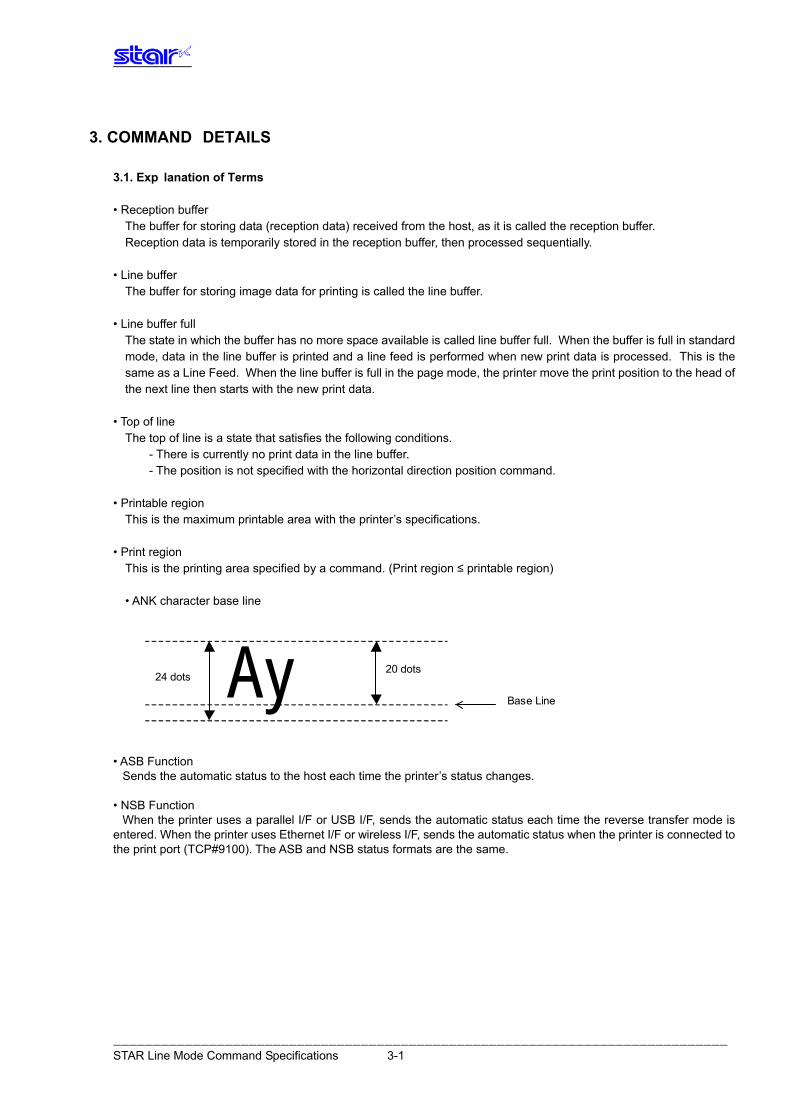
• ANK character base line
Ay Base Line
24 dots 20 dots
• ASB Function
Sends the automatic status to the host each time the printer’s status changes. • NSB Function
When the printer uses a parallel I/F or USB I/F, sends the automatic status each time the reverse transfer mode is entered. When the printer uses Ethernet I/F or wireless I/F, sends the automatic status when the printer is connected to the print port (TCP#9100). The ASB and NSB status formats are the same.
――――――――――――――――――――――――――――――――――――――――――――――――――――――――――――――――――――――――――――― STAR Line Mode Command Specifications 3-1
3.2. Excep tion Processing 1) Undefined codes
Codes from <00>H to <1F>H are targeted. When codes not defined as commands in this region are received, they are discarded. (Ex.) If processing the data string of <30>H<31>H<03>H<32>H<0A>H<33>H, the printer will discard <03>H as an
undefined code. 2) Undefined commands
When data continuing the codes of ESC, FS, GS, DLE are codes not defined as commands, ESC, FS,GS and subsequent codes are discarded.
(Ex.) If processing the data string of <30>H<1B>H<22>H<31>H<32>H, the printer will read and discard
<1B>H<22>H as an undefined command. 3) Settings outside of the defined area
Processing values outside of the defined area in commands accompanying arguments, those commands are ignored and the preset values are unchanged. The processing of commands is terminated at the point values outside of the defined region are processed in arguments having a plurality of commands. Data after that is processed as normal data.
(Ex.) If processing the data string of <1B>H<52>H<15>H, the printer will discard the data string of
<1B>H<52>H<15>H because although <1B>H<52>H is defined as a commands (ESC R), the argument <15>H is outside of the definition. Therefore, the international character set that is already set experiences no change.
――――――――――――――――――――――――――――――――――――――――――――――――――――――――――――――――――――――――――――― STAR Line Mode Command Specifications 3-2
3.3. Standard Command Details
3.3.1. Font style and Character Set
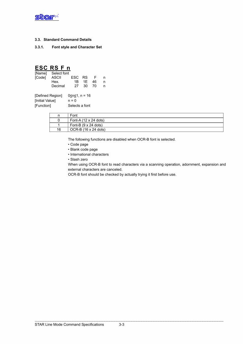
ESC RS F n [Name] Select font [Code] ASCII ESC RS F n Hex. 1B 1E 46 n Decimal 27 30 70 n [Defined Region] 0≤n≤1, n = 16 [Initial Value] n = 0 [Function] Selects a font
n Font 0 Font-A (12 x 24 dots) 1 Font-B (9 x 24 dots)
16 OCR-B (16 x 24 dots) The following functions are disabled when OCR-B font is selected. • Code page • Blank code page • International characters • Slash zero When using OCR-B font to read characters via a scanning operation, adornment, expansion and
external characters are canceled. OCR-B font should be checked by actually trying it first before use.
――――――――――――――――――――――――――――――――――――――――――――――――――――――――――――――――――――――――――――― STAR Line Mode Command Specifications 3-3
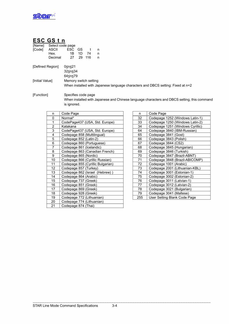
ESC GS t n [Name] Select code page [Code] ASCII ESC GS t n Hex. 1B 1D 74 n Decimal 27 29 116 n [Defined Region] 0≤n≤21 32≤n≤34 64≤n≤79 [Initial Value] Memory switch setting When installed with Japanese language characters and DBCS setting: Fixed at n=2 [Function] Specifies code page When installed with Japanese and Chinese language characters and DBCS setting, this command
is ignored.
n Code Page n Code Page 0 Normal* 32 Codepage 1252 (Windows Latin-1) 1 CodePage437 (USA, Std. Europe) 33 Codepage 1250 (Windows Latin-2) 2 Katakana 34 Codepage 1251 (Windows Cyrillic) 3 CodePage437 (USA, Std. Europe) 64 Codepage 3840 (IBM-Russian) 4 Codepage 858 (Multilingual) 65 Codepage 3841 (Gost) 5 Codepage 852 (Latin-2) 66 Codepage 3843 (Polish) 6 Codepage 860 (Portuguese) 67 Codepage 3844 (CS2) 7 Codepage 861 (Icelandic) 68 Codepage 3845 (Hungarian) 8 Codepage 863 (Canadian French) 69 Codepage 3846 (Turkish) 9 Codepage 865 (Nordic) 70 Codepage 3847 (Brazil-ABNT)
10 Codepage 866 (Cyrillic Russian) 71 Codepage 3848 (Brazil-ABICOMP) 11 Codepage 855 (Cyrillic Bulgarian) 72 Codepage 1001 (Arabic) 12 Codepage 857 (Turkey) 73 Codepage 2001 (Lithuanian-KBL) 13 Codepage 862 (Israel (Hebrew) ) 74 Codepage 3001 (Estonian-1) 14 Codepage 864 (Arabic) 75 Codepage 3002 (Estonian-2) 15 Codepage 737 (Greek) 76 Codepage 3011 (Latvian-1) 16 Codepage 851 (Greek) 77 Codepage 3012 (Latvian-2) 17 Codepage 869 (Greek) 78 Codepage 3021 (Bulgarian) 18 Codepage 928 (Greek) 79 Codepage 3041 (Maltese) 19 Codepage 772 (Lithuanian) 255 User Setting Blank Code Page 20 Codepage 774 (Lithuanian) 21 Codepage 874 (Thai)
――――――――――――――――――――――――――――――――――――――――――――――――――――――――――――――――――――――――――――― STAR Line Mode Command Specifications 3-4
――――――――――――――――――――――――――――――――――――――――――――――――――――――――――――――――――――――――――――― STAR Line Mode Command Specifications 3-5
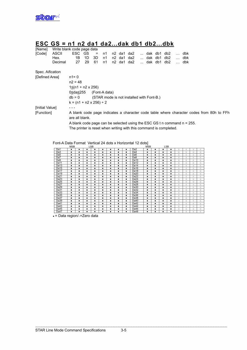
ESC GS = n1 n2 da1 da2...dak db1 db2...dbk [Name] Write blank code page data [Code] ASCII ESC GS = n1 n2 da1 da2 ... dak db1 db2 … dbk Hex. 1B 1D 3D n1 n2 da1 da2 ... dak db1 db2 … dbk Decimal 27 29 61 n1 n2 da1 da2 ... dak db1 db2 … dbk Spec. Aification [Defined Area] n1= 0 n2 = 48 1≤(n1 + n2 x 256) 0≤da≤255 (Font-A data) db = 0 (STAR mode is not installed with Font-B.) k = (n1 + n2 x 256) ÷ 2 [Initial Value] - - - [Function] A blank code page indicates a character code table where character codes from 80h to FFh
are all blank. A blank code page can be selected using the ESC GS t n command n = 255. The printer is reset when writing with this command is completed.
Font-A Data Format Vertical 24 dots x Horizontal 12 dots] MSB LSB MSB LSB Da1 ● ● ● ● ● ● ● ● Da2 ● ● ● ● ○ ○ ○ ○ Da3 ● ● ● ● ● ● ● ● Da4 ● ● ● ● ○ ○ ○ ○ Da5 ● ● ● ● ● ● ● ● Da6 ● ● ● ● ○ ○ ○ ○ Da7 ● ● ● ● ● ● ● ● Da8 ● ● ● ● ○ ○ ○ ○ Da9 ● ● ● ● ● ● ● ● Da10 ● ● ● ● ○ ○ ○ ○ Da11 ● ● ● ● ● ● ● ● Da12 ● ● ● ● ○ ○ ○ ○ Da13 ● ● ● ● ● ● ● ● Da14 ● ● ● ● ○ ○ ○ ○ Da15 ● ● ● ● ● ● ● ● Da16 ● ● ● ● ○ ○ ○ ○ Da17 ● ● ● ● ● ● ● ● Da18 ● ● ● ● ○ ○ ○ ○ Da19 ● ● ● ● ● ● ● ● Da20 ● ● ● ● ○ ○ ○ ○ Da21 ● ● ● ● ● ● ● ● Da22 ● ● ● ● ○ ○ ○ ○ Da23 ● ● ● ● ● ● ● ● Da24 ● ● ● ● ○ ○ ○ ○ Da25 ● ● ● ● ● ● ● ● Da26 ● ● ● ● ○ ○ ○ ○ Da27 ● ● ● ● ● ● ● ● Da28 ● ● ● ● ○ ○ ○ ○ Da29 ● ● ● ● ● ● ● ● Da30 ● ● ● ● ○ ○ ○ ○ Da31 ● ● ● ● ● ● ● ● Da32 ● ● ● ● ○ ○ ○ ○ Da33 ● ● ● ● ● ● ● ● Da34 ● ● ● ● ○ ○ ○ ○ Da35 ● ● ● ● ● ● ● ● Da36 ● ● ● ● ○ ○ ○ ○ Da37 ● ● ● ● ● ● ● ● Da38 ● ● ● ● ○ ○ ○ ○ Da39 ● ● ● ● ● ● ● ● Da40 ● ● ● ● ○ ○ ○ ○ Da41 ● ● ● ● ● ● ● ● Da42 ● ● ● ● ○ ○ ○ ○ Da43 ● ● ● ● ● ● ● ● Da44 ● ● ● ● ○ ○ ○ ○ Da45 ● ● ● ● ● ● ● ● Da46 ● ● ● ● ○ ○ ○ ○ Da47 ● ● ● ● ● ● ● ● Da48 ● ● ● ● ○ ○ ○ ○
● = Data region/○=Zero data
――――――――――――――――――――――――――――――――――――――――――――――――――――――――――――――――――――――――――――― STAR Line Mode Command Specifications 3-6
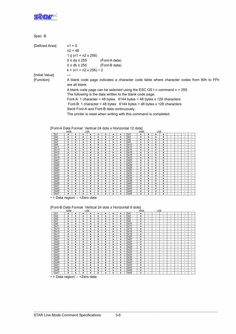
Spec. B. [Defined Area] n1 = 0
n2 = 48 1 ≤ (n1 + n2 x 256) 0 ≤ da ≤ 255 (Font-A data)
0 ≤ db ≤ 255 (Font-B data) k = (n1 + n2 x 256) ÷ 2 [Initial Value] --- [Function] A blank code page indicates a character code table where character codes from 80h to FFh are all blank.
A blank code page can be selected using the ESC GS t n command n = 255. The following is the data written to the blank code page. Font-A: 1 character = 48 bytes 6144 bytes = 48 bytes x 128 characters
Font-B: 1 character = 48 bytes 6144 bytes = 48 bytes x 128 characters
Send Font-A and Font-B data continuously. The printer is reset when writing with this command is completed.
[Font-A Data Format Vertical 24 dots x Horizontal 12 dots] MSB LSB MSB LSB Da1 ● ● ● ● ● ● ● ● Da2 ● ● ● ● ○ ○ ○ ○ Da3 ● ● ● ● ● ● ● ● Da4 ● ● ● ● ○ ○ ○ ○ Da5 ● ● ● ● ● ● ● ● Da6 ● ● ● ● ○ ○ ○ ○ Da7 ● ● ● ● ● ● ● ● Da8 ● ● ● ● ○ ○ ○ ○ Da9 ● ● ● ● ● ● ● ● Da10 ● ● ● ● ○ ○ ○ ○ Da11 ● ● ● ● ● ● ● ● Da12 ● ● ● ● ○ ○ ○ ○ Da13 ● ● ● ● ● ● ● ● Da14 ● ● ● ● ○ ○ ○ ○ Da15 ● ● ● ● ● ● ● ● Da16 ● ● ● ● ○ ○ ○ ○ Da17 ● ● ● ● ● ● ● ● Da18 ● ● ● ● ○ ○ ○ ○ Da19 ● ● ● ● ● ● ● ● Da20 ● ● ● ● ○ ○ ○ ○ Da21 ● ● ● ● ● ● ● ● Da22 ● ● ● ● ○ ○ ○ ○ Da23 ● ● ● ● ● ● ● ● Da24 ● ● ● ● ○ ○ ○ ○ Da25 ● ● ● ● ● ● ● ● Da26 ● ● ● ● ○ ○ ○ ○ Da27 ● ● ● ● ● ● ● ● Da28 ● ● ● ● ○ ○ ○ ○ Da29 ● ● ● ● ● ● ● ● Da30 ● ● ● ● ○ ○ ○ ○ Da31 ● ● ● ● ● ● ● ● Da32 ● ● ● ● ○ ○ ○ ○ Da33 ● ● ● ● ● ● ● ● Da34 ● ● ● ● ○ ○ ○ ○ Da35 ● ● ● ● ● ● ● ● Da36 ● ● ● ● ○ ○ ○ ○ Da37 ● ● ● ● ● ● ● ● Da38 ● ● ● ● ○ ○ ○ ○ Da39 ● ● ● ● ● ● ● ● Da40 ● ● ● ● ○ ○ ○ ○ Da41 ● ● ● ● ● ● ● ● Da42 ● ● ● ● ○ ○ ○ ○ Da43 ● ● ● ● ● ● ● ● Da44 ● ● ● ● ○ ○ ○ ○ Da45 ● ● ● ● ● ● ● ● Da46 ● ● ● ● ○ ○ ○ ○ Da47 ● ● ● ● ● ● ● ● Da48 ● ● ● ● ○ ○ ○ ○
• = Data region/ ○ =Zero data
[Font-B Data Format Vertical 24 dots x Horizontal 9 dots] MSB LSB MSB LSB Da1 ● ● ● ● ● ● ● ● Da2 ● ○ ○ ○ ○ ○ ○ ○ Da3 ● ● ● ● ● ● ● ● Da4 ● ○ ○ ○ ○ ○ ○ ○ Da5 ● ● ● ● ● ● ● ● Da6 ● ○ ○ ○ ○ ○ ○ ○ Da7 ● ● ● ● ● ● ● ● Da8 ● ○ ○ ○ ○ ○ ○ ○ Da9 ● ● ● ● ● ● ● ● Da10 ● ○ ○ ○ ○ ○ ○ ○ Da11 ● ● ● ● ● ● ● ● Da12 ● ○ ○ ○ ○ ○ ○ ○ Da13 ● ● ● ● ● ● ● ● Da14 ● ○ ○ ○ ○ ○ ○ ○ Da15 ● ● ● ● ● ● ● ● Da16 ● ○ ○ ○ ○ ○ ○ ○ Da17 ● ● ● ● ● ● ● ● Da18 ● ○ ○ ○ ○ ○ ○ ○ Da19 ● ● ● ● ● ● ● ● Da20 ● ○ ○ ○ ○ ○ ○ ○ Da21 ● ● ● ● ● ● ● ● Da22 ● ○ ○ ○ ○ ○ ○ ○ Da23 ● ● ● ● ● ● ● ● Da24 ● ○ ○ ○ ○ ○ ○ ○ Da25 ● ● ● ● ● ● ● ● Da26 ● ○ ○ ○ ○ ○ ○ ○ Da27 ● ● ● ● ● ● ● ● Da28 ● ○ ○ ○ ○ ○ ○ ○ Da29 ● ● ● ● ● ● ● ● Da30 ● ○ ○ ○ ○ ○ ○ ○ Da31 ● ● ● ● ● ● ● ● Da32 ● ○ ○ ○ ○ ○ ○ ○ Da33 ● ● ● ● ● ● ● ● Da34 ● ○ ○ ○ ○ ○ ○ ○ Da35 ● ● ● ● ● ● ● ● Da36 ● ○ ○ ○ ○ ○ ○ ○ Da37 ● ● ● ● ● ● ● ● Da38 ● ○ ○ ○ ○ ○ ○ ○ Da39 ● ● ● ● ● ● ● ● Da40 ● ○ ○ ○ ○ ○ ○ ○ Da41 ● ● ● ● ● ● ● ● Da42 ● ○ ○ ○ ○ ○ ○ ○ Da43 ● ● ● ● ● ● ● ● Da44 ● ○ ○ ○ ○ ○ ○ ○ Da45 ● ● ● ● ● ● ● ● Da46 ● ○ ○ ○ ○ ○ ○ ○ Da47 ● ● ● ● ● ● ● ● Da48 ● ○ ○ ○ ○ ○ ○ ○
• = Data region/ ○ =Zero data
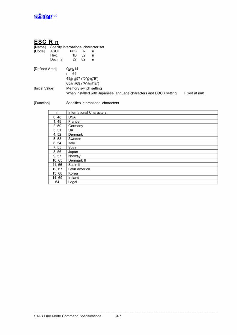
ESC R n [Name] Specify international character set [Code] ASCII R n ESC Hex. 1B 52 n Decimal 27 82 n [Defined Area] 0≤n≤14 n = 64 48≤n≤57 (”0”≤n≤”9”) 65≤n≤69 (”A”≤n≤”E”) [Initial Value] Memory switch setting When installed with Japanese language characters and DBCS setting: Fixed at n=8 [Function] Specifies international characters
n International Characters 0, 48 USA 1, 49 France 2, 50 Germany 3, 51 UK 4, 52 Denmark 5, 53 Sweden 6, 54 Italy 7, 55 Spain 8, 56 Japan 9, 57 Norway
10, 65 Denmark II 11, 66 Spain II 12, 67 Latin America 13, 68 Korea 14, 69 Ireland
64 Legal
――――――――――――――――――――――――――――――――――――――――――――――――――――――――――――――――――――――――――――― STAR Line Mode Command Specifications 3-7
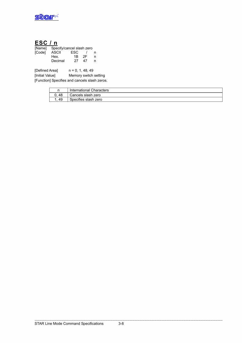
ESC / n [Name] Specify/cancel slash zero [Code] ASCII ESC / n Hex. 1B 2F n Decimal 27 47 n [Defined Area] n = 0, 1, 48, 49 [Initial Value] Memory switch setting [Function] Specifies and cancels slash zeros.
n International Characters 0, 48 Cancels slash zero 1, 49 Specifies slash zero
――――――――――――――――――――――――――――――――――――――――――――――――――――――――――――――――――――――――――――― STAR Line Mode Command Specifications 3-8
ESC SP n [Name] Set ANK right space [Code] ASCII ESC SP n Hex. 1B 20 n Decimal 27 32 n [Defined Area] 0≤n≤15 48≤n≤57 (”0”≤n≤”9”) 65≤n≤70 (”A”≤n≤”F”) [Initial Value] Memory switch setting [Function] Specify the right space amount of ANK characters in n dots. The ANK character width is "left space amount” + "ANK font dot count” + right space amount.” (See the information on character specifications in the appropriate printer specifications manual
for details on the ANK font dot count.) Character spacing can be specified also with the following commands. • Specify 12 dot pitch (ESC M) • Specify 14 dot pitch (ESC g) • Specify 15 dot pitch (ESC P) • Specify 16 dot pitch (ESC :)
Standard mode and page mode can be set independently of each other.
――――――――――――――――――――――――――――――――――――――――――――――――――――――――――――――――――――――――――――― STAR Line Mode Command Specifications 3-9
ESC M [Name] Specify 12 dot pitch [Code] ASCII ESC M Hex. 1B 4D Decimal 27 77 [Defined Area] - - - [Initial Value] Memory switch setting [Function] Specify the right space amount of ANK characters in 0 dots. The ANK character width is "left space amount” + "ANK font dot count” + right space amount.” (See the information on character specifications in the appropriate printer specifications manual for details on the ANK font dot count.) Standard mode and page mode can be set independently of each other.
ESC P [Name] Specify 15 dot pitch [Code] ASCII ESC P Hex. 1B 50 Decimal 27 80 [Defined Area] - - - [Initial Value] Memory switch setting [Function] Specify the right space amount of ANK characters in 3 dots. The ANK character width is "left space amount” + "ANK font dot count” + right space amount.” (See the information on character specifications in the appropriate printer specifications manual for details on the ANK font dot count.) Standard mode and page mode can be set independently of each other.
ESC : [Name] Specify 16 dot pitch [Code] ASCII ESC : Hex. 1B 3A Decimal 27 58 [Defined Area] - - - [Initial Value] Memory switch setting [Function] Specify the right space amount of ANK characters in 4 dots. The ANK character width is "left space amount” + "ANK font dot count” + right space amount.” (See the information on character specifications in the appropriate printer specifications manual for details on the ANK font dot count.) Standard mode and page mode can be set independently of each other.
――――――――――――――――――――――――――――――――――――――――――――――――――――――――――――――――――――――――――――― STAR Line Mode Command Specifications 3-10
ESC g [Name] Specify 14 dot pitch [Code] ASCII ESC g Hex. 1B 67 Decimal 27 103 [Defined Area] - - - [Initial Value] Memory switch setting [Function] Specify the right space amount of ANK characters in 2 dots. The ANK character width is "left space amount” + "ANK font dot count” + right space amount.” (See the information on character specifications in the appropriate printer specifications manual for details on the ANK font dot count.) Standard mode and page mode can be set independently of each other. Specification A This command is enabled only when the memory switch setting is set for DBCS (2 byte countries).
It is ignored when the memory switch setting is set for SBCS (1 byte countries). Specification B This command is enabled for both when the memory switch setting is set for either DBCS (2 byte
countries) or SBCS (1 byte countries).
――――――――――――――――――――――――――――――――――――――――――――――――――――――――――――――――――――――――――――― STAR Line Mode Command Specifications 3-11
3.3.2. Character Expansion Settings
ESC i n1 n2 [Name] Set/cancel the double wide/high [Code] ASCII ESC i n1 n2 Hex. 1B 69 n1 n2 Decimal 27 105 n1 n2 [Defined Area] 0≤n1≤5 48≤n1≤53 (”0”≤n1≤”5”)
0≤n2≤5 48≤n2≤53 (”0”≤n2≤”5”) [Initial Value] n1 = 0 (Double high cancelled) n2 = 0 (Double wide cancelled) [Function] Specifies/cancels double high/wide for ANK characters and Kanji characters. This command is ignored if either n1 or n2 is outside of the defined area.
n1 Expanded high 0, 48 Cancels expanded high 1, 49 Specifies 2x high expansion 2, 50 Specifies 3x high expansion 3, 51 Specifies 4x high expansion 4, 52 Specifies 5x high expansion 5, 53 Specifies 6x high expansion
n2 Expanded wide
0, 48 Cancels expanded wide 1, 49 Specifies 2x wide expansion 2, 50 Specifies 3x wide expansion 3, 51 Specifies 4x wide expansion 4, 52 Specifies 5x wide expansion 5, 53 Specifies 6x wide expansion
――――――――――――――――――――――――――――――――――――――――――――――――――――――――――――――――――――――――――――― STAR Line Mode Command Specifications 3-12
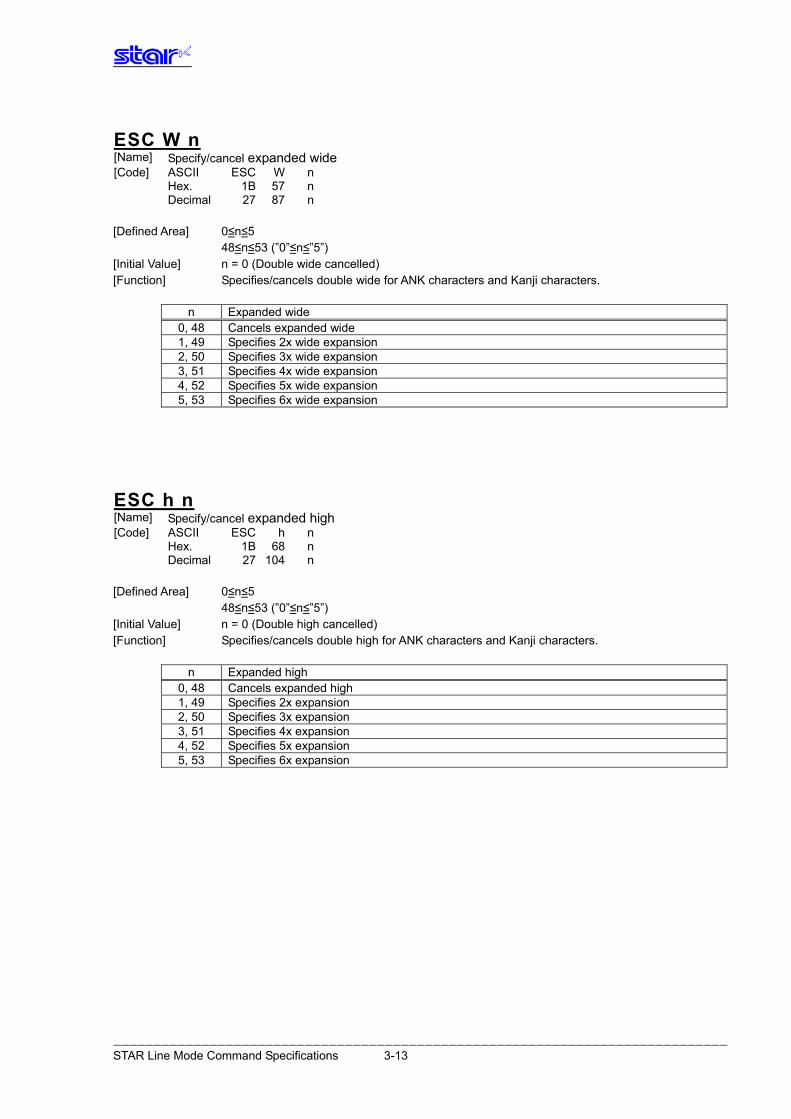
ESC W n Specify/cancel expanded wide [Name]
[Code] ASCII ESC W n Hex. 1B 57 n Decimal 27 87 n [Defined Area] 0≤n≤5 48≤n≤53 (”0”≤n≤”5”) [Initial Value] n = 0 (Double wide cancelled) [Function] Specifies/cancels double wide for ANK characters and Kanji characters.
n Expanded wide 0, 48 Cancels expanded wide 1, 49 Specifies 2x wide expansion 2, 50 Specifies 3x wide expansion 3, 51 Specifies 4x wide expansion 4, 52 Specifies 5x wide expansion 5, 53 Specifies 6x wide expansion
ESC h n Specify/cancel expanded high [Name]
[Code] ASCII ESC h n Hex. 1B 68 n Decimal 27 104 n [Defined Area] 0≤n≤5 48≤n≤53 (”0”≤n≤”5”) [Initial Value] n = 0 (Double high cancelled) [Function] Specifies/cancels double high for ANK characters and Kanji characters.
n Expanded high 0, 48 Cancels expanded high 1, 49 Specifies 2x expansion 2, 50 Specifies 3x expansion 3, 51 Specifies 4x expansion 4, 52 Specifies 5x expansion 5, 53 Specifies 6x expansion
――――――――――――――――――――――――――――――――――――――――――――――――――――――――――――――――――――――――――――― STAR Line Mode Command Specifications 3-13
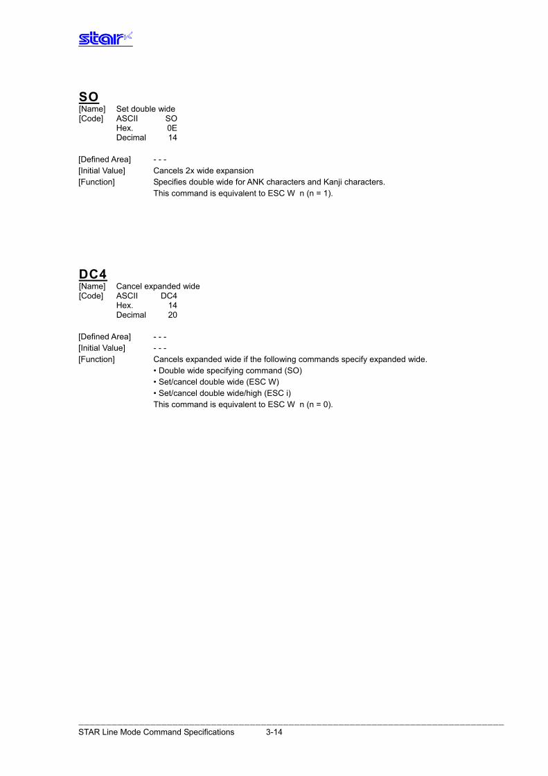
SO [Name] Set double wide [Code] ASCII SO Hex. 0E Decimal 14 [Defined Area] - - - [Initial Value] Cancels 2x wide expansion [Function] Specifies double wide for ANK characters and Kanji characters. This command is equivalent to ESC W n (n = 1).
DC4 [Name] Cancel expanded wide [Code] ASCII DC4 Hex. 14 Decimal 20 [Defined Area] - - - [Initial Value] - - - [Function] Cancels expanded wide if the following commands specify expanded wide.
• Double wide specifying command (SO) • Set/cancel double wide (ESC W) • Set/cancel double wide/high (ESC i)
This command is equivalent to ESC W n (n = 0).
――――――――――――――――――――――――――――――――――――――――――――――――――――――――――――――――――――――――――――― STAR Line Mode Command Specifications 3-14

ESC SO [Name] Set double high [Code] ASCII ESC SO Hex. 1B 0E Decimal 27 14 [Defined Area] - - - [Initial Value] Double high expansion cancelled. [Function] Specifies double high for ANK characters and Kanji characters. This command is equivalent to ESC h n (n = 1).
ESC DC4 [Name] Cancel expanded high [Code] ASCII ESC DC4 Hex. 1B 14 Decimal 27 20 [Defined Area] - - - [Initial Value] - - - [Function] Cancels expanded high if the following commands specify expanded high.
• Double high specifying command (ESC SO) • Set/cancel the double high (ESC h) • Set/cancel double wide/high (ESC i)
This command is equivalent to ESC h n (n = 0).
――――――――――――――――――――――――――――――――――――――――――――――――――――――――――――――――――――――――――――― STAR Line Mode Command Specifications 3-15
3.3.3. Prin t Mode
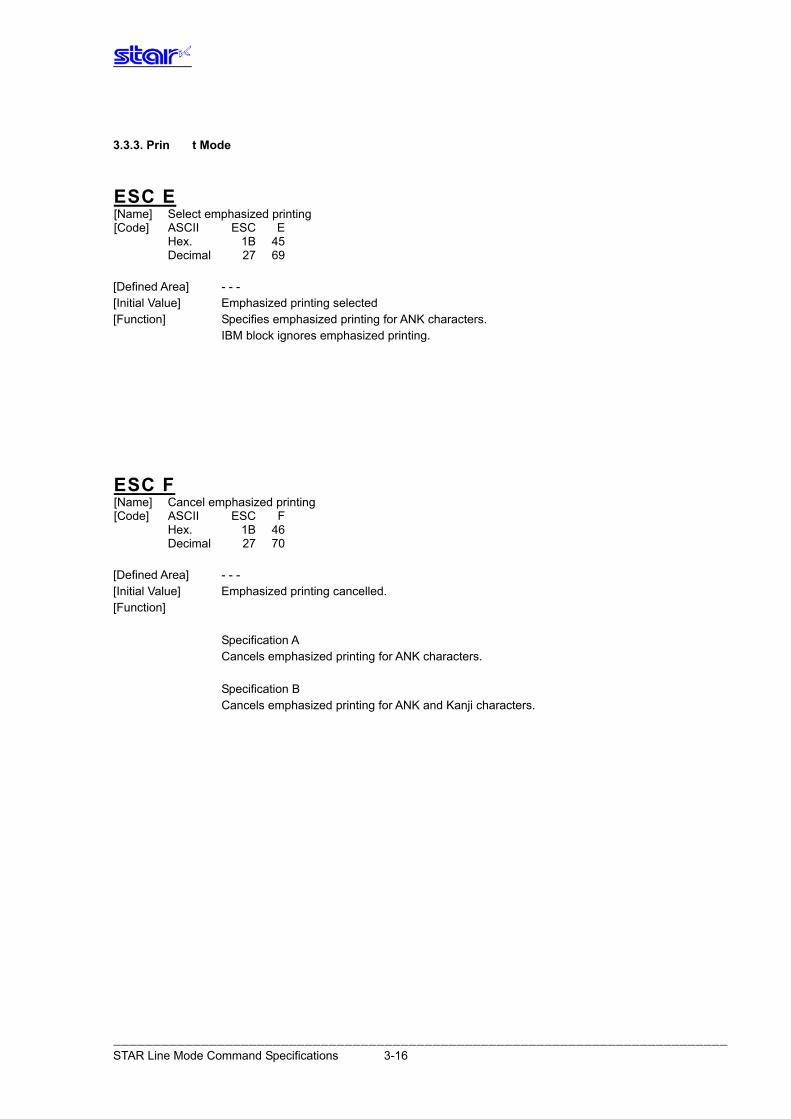
ESC E [Name] Select emphasized printing [Code] ASCII ESC E Hex. 1B 45 Decimal 27 69 [Defined Area] - - - [Initial Value] Emphasized printing selected [Function] Specifies emphasized printing for ANK characters. IBM block ignores emphasized printing.
ESC F [Name] Cancel emphasized printing [Code] ASCII ESC F Hex. 1B 46 Decimal 27 70 [Defined Area] - - - [Initial Value] Emphasized printing cancelled. [Function] Specification A Cancels emphasized printing for ANK characters. Specification B Cancels emphasized printing for ANK and Kanji characters.
――――――――――――――――――――――――――――――――――――――――――――――――――――――――――――――――――――――――――――― STAR Line Mode Command Specifications 3-16
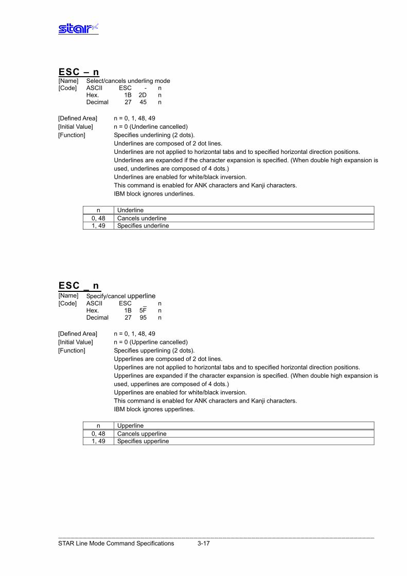
ESC – n [Name] Select/cancels underling mode [Code] ASCII ESC - n Hex. 1B 2D n Decimal 27 45 n [Defined Area] n = 0, 1, 48, 49 [Initial Value] n = 0 (Underline cancelled) [Function] Specifies underlining (2 dots).
Underlines are composed of 2 dot lines. Underlines are not applied to horizontal tabs and to specified horizontal direction positions.
Underlines are expanded if the character expansion is specified. (When double high expansion is used, underlines are composed of 4 dots.)
Underlines are enabled for white/black inversion. This command is enabled for ANK characters and Kanji characters. IBM block ignores underlines.
n Underline 0, 48 Cancels underline 1, 49 Specifies underline
ESC _ n Specify/cancel upperline [Name]
[Code] ASCII ESC _ n Hex. 1B 5F n Decimal 27 95 n [Defined Area] n = 0, 1, 48, 49 [Initial Value] n = 0 (Upperline cancelled) [Function] Specifies upperlining (2 dots). Upperlines are composed of 2 dot lines. Upperlines are not applied to horizontal tabs and to specified horizontal direction positions. Upperlines are expanded if the character expansion is specified. (When double high expansion is
used, upperlines are composed of 4 dots.) Upperlines are enabled for white/black inversion. This command is enabled for ANK characters and Kanji characters. IBM block ignores upperlines.
n Upperline 0, 48 Cancels upperline 1, 49 Specifies upperline
――――――――――――――――――――――――――――――――――――――――――――――――――――――――――――――――――――――――――――― STAR Line Mode Command Specifications 3-17
ESC 4 [Name] Select white/black inverted printing [Code] ASCII ESC 4 Hex. 1B 34 Decimal 27 52 [Defined Area] - - - [Initial Value] White/black inversion cancelled [Function] Specifies white/black inversion for ANK characters and Kanji characters. IBM block ignores white/black inversion.
ESC 5 [Name] Cancel white/black inversion [Code] ASCII ESC 5 Hex. 1B 35 Decimal 27 53 [Defined Area] - - - [Initial Value] White/black inversion cancelled [Function] Cancels white/black inversion for ANK characters and Kanji characters.
――――――――――――――――――――――――――――――――――――――――――――――――――――――――――――――――――――――――――――― STAR Line Mode Command Specifications 3-18
SI [Name] Select upside-down printing [Code] ASCII SI Hex. 0F Decimal 15 [Defined Area] - - - [Initial Value] Upside-down cancelled [Function] Specifies upside-down printing This command is enabled only when at the top of the line. Upside down and right-side up characters cannot both exist in the same line. This command is enabled for following. • ANK characters • Kanji characters • Bit images • Logos • Bar codes
DC2 [Name] Cancel upside-down printing [Code] ASCII DC2 Hex. 12 Decimal 18 [Defined Area] - - - [Initial Value] Upside-down printing cancelled [Function] Cancels upside-down printing This command is enabled only when at the top of the line.
――――――――――――――――――――――――――――――――――――――――――――――――――――――――――――――――――――――――――――― STAR Line Mode Command Specifications 3-19
3.3.4. L ine Spacing
LF [Name] Line feed [Code] ASCII LF Hex. 0A Decimal 10 [Defined Area] - - - [Initial Value] - - - [Function] Feeds the currently specified amount of paper.
If print data exists in the line buffer, it prints that data. The initial value for the amount of paper is set according to the memory switch settings.
CR [Name] Carriage return (line feed) [Code] ASCII CR Hex. 0D Decimal 13 [Defined Area] - - - [Initial Value] - - - [Function] When the CR code is enabled, the CR code functions in the same way as the LF code.
If the CR code is disabled, it ignores 1 byte. Enabling and disabling the CR code is done using the memory switch settings.
ESC a n [Name] Feed paper n lines [Code] ASCII ESC a n Hex. 1B 61 n Decimal 27 97 n [Defined Area] 1≤n≤127 [Initial Value] - - - [Function] Executes a paper feed for (the currently specified line feed amount x n). If print data exists in the
line buffer, it prints that data. The initial value for the amount of paper is set according to the memory switch settings.
――――――――――――――――――――――――――――――――――――――――――――――――――――――――――――――――――――――――――――― STAR Line Mode Command Specifications 3-20
ESC z n [Name] Select line feed amount [Code] ASCII ESC z n Hex. 1B 7A n Decimal 27 122 n [Defined Area] n = 1, 49 [Initial Value] Memory switch setting [Function] Specifies the line feed amount. Standard mode and page mode can be set independently of each other.
n Line feed amount 1, 49 Specifies 4 mm line feed amount
ESC 0 [Name] Specify line spacing to 3 mm [Code] ASCII ESC 0 Hex. 1B 30 Decimal 27 48 [Defined Area] - - - [Initial Value] Memory switch setting [Function] Specifies the line feed amount to 3 mm. Standard mode and page mode can be set independently of each other.
――――――――――――――――――――――――――――――――――――――――――――――――――――――――――――――――――――――――――――― STAR Line Mode Command Specifications 3-21
ESC J n [Name] n/4 mm line feed [Code] ASCII ESC J n Hex. 1B 4A n Decimal 27 74 n [Defined Area] 1≤n≤255 [Initial Value] - - - [Function] Executes a n/4mm paper feed. If print data exists in the line buffer, it prints that data. Using this command will intermittently feed paper, therefore, it is normally recommended that this
command not be used.
ESC I n [Name] n/8mm line feed [Code] ASCII ESC I n Hex. 1B 49 n Decimal 27 73 n [Defined Area] 1≤n≤255 [Initial Value] - - - [Function] Executes a n/8mm paper feed. If print data exists in the line buffer, it prints that data. Using this command will intermittently feed paper, therefore, it is normally recommended that this
command not be used.
――――――――――――――――――――――――――――――――――――――――――――――――――――――――――――――――――――――――――――― STAR Line Mode Command Specifications 3-22
3.3.5. Pa ge Control Commands
FF [Name] Form feed [Code] ASCII FF Hex. 0C Decimal 12 [Defined Area] - - - [Initial Value] - - - [Function] Executes a form feed. If the current position is at the top of the page, it form feeds to the top of the next page.
If there is data existing in the line buffer when executing a form feed, it prints that data, then executes the form feed.
However, by printing data remaining in the buffer, and moving to the top of the next page, a form feed is considered to have been executed, so form feed is not performed.
Invalid in page mode.
ESC C n [Name] Set page length to n lines [Code] ASCII ESC C n Hex. 1B 43 n Decimal 27 67 n [Defined Area] 1≤n≤127 [Initial Value] (Form feed amount initial value x 42) [Function] The position whereat this command is processed is considered the top of the page and sets the
page length to (current form feed amount x n). This command cancels the bottom margin setting when setting page length. The page length set using this command is unaffected by changing the form feed amount later. Moving to the top of the page is performed using the following commands. • Form feed command (FF): Executes a form feed. • Cutter command (ESC d n): Sets cutter position at top of page. • Raster command (ESC * r B): Sets top of page when quitting raster mode. • Error cancel operations: Sets position when quitting error cancellation operations
at top of page.
――――――――――――――――――――――――――――――――――――――――――――――――――――――――――――――――――――――――――――― STAR Line Mode Command Specifications 3-23
ESC C 0 n [Name] Set page length to n x 24 mm units [Code] ASCII ESC C 0 n Hex. 1B 43 00 n Decimal 27 67 0 n [Defined Area] 1≤n≤22 [Initial Value] (Form feed amount initial value x 42) [Function] The position whereat this command is processed is considered the top of the page and sets the
page length to (n x 24 mm). This command cancels the bottom margin setting when setting page length. The page length set using this command is unaffected by changing the form feed amount later. Moving to the top of the page is performed using the following commands. • Form feed command (FF): Executes a form feed. • Cutter command (ESC d n): Sets cutter position at top of page. • Raster command (ESC * r B): Sets top of page when quitting raster mode. • Error cancel operations: Sets position when quitting error cancellation operations
at top of page.
――――――――――――――――――――――――――――――――――――――――――――――――――――――――――――――――――――――――――――― STAR Line Mode Command Specifications 3-24
VT [Name] Feed paper to vertical tab position [Code] ASCII VT Hex. 0B Decimal 11 [Defined Area] - - - [Initial Value] - - - [Function] Feeds paper to the next vertical tab position. This command is ignored if there are no tabs set. If a vertical tab is set, and the current position is the same as the vertical tab position, or if it is
below that position, it feeds paper to the top of the next page. If data exists in the line buffer when feeing paper to the vertical tab position, it executes the paper
feed to the vertical tab position after printing that data. However, if moved to the vertical tab position by printing data remaining in the buffer, the move to the vertical tab position is considered to have been executed, so a move to the next vertical tab position is not performed.
There is no initial value for the vertical tab. Invalid in page mode.
――――――――――――――――――――――――――――――――――――――――――――――――――――――――――――――――――――――――――――― STAR Line Mode Command Specifications 3-25
ESC B n1 n2…nk NUL [Name] Set vertical tab position [Code] ASCII ESC B n1 n2 ... nk NUL Hex. 1B 42 n1 n2 ... nk 00 Decimal 27 66 n1 n2 ... nk 0 [Defined Area] 1≤n≤255 0≤k≤16 [Initial Value] - - - [Function] Sets the vertical tab to the (current form feed amount x n) position. All other vertical tabs set before setting the vertical tab using this command are cancelled A maximum of 16 vertical tabs can be set. However, the tab position must satisfy the condition of
1≤n1≤n2... ≤nk. When receiving such illegal codes, tabs up to the illegal code are set, but those after the illegal code are discarded up to the NUL code so illegal code tab are not set.
The vertical tab set using this command is unaffected by changing the form feed amount later. Vertical tabs set using the ESC B NUL command are cleared. There is no initial value for the vertical tab.
ESC B NUL [Name] Clear vertical tab position [Code] ASCII ESC B NUL Hex. 1B 42 00 Decimal 27 66 0 [Defined Area] - - - [Initial Value] - - - [Function] Clears the currently set vertical tab.
――――――――――――――――――――――――――――――――――――――――――――――――――――――――――――――――――――――――――――― STAR Line Mode Command Specifications 3-26
3.3.6. Ho rizontal Direction Printing Position
ESC l n [Name] Set left margin [Code] ASCII ESC l n Hex. 1B 6C n Decimal 27 108 n [Defined Area] 0≤n≤255 [Initial Value] n = 0 [Function] Uses the left edge as a standard to set the left margin as (current ANK character pitch x n). Character pitch includes the space between characters and expansion settings are enabled. The left margin set using this command is unaffected by changing the character pitch. This command is ignored if settings are for a printing region less than 36 mm. Specification A Setting this command partway will take affect from the next line. Specification B This command is enabled only when at the top of the line.
――――――――――――――――――――――――――――――――――――――――――――――――――――――――――――――――――――――――――――― STAR Line Mode Command Specifications 3-27
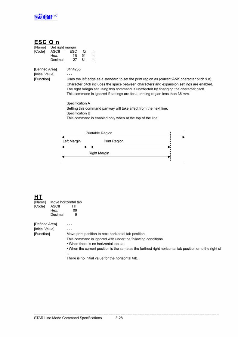
ESC Q n [Name] Set right margin [Code] ASCII ESC Q n Hex. 1B 51 n Decimal 27 81 n
Printable Region Left Margin Print Region Right Margin
[Defined Area] 0≤n≤255 [Initial Value] - - - [Function] Uses the left edge as a standard to set the print region as (current ANK character pitch x n). Character pitch includes the space between characters and expansion settings are enabled. The right margin set using this command is unaffected by changing the character pitch. This command is ignored if settings are for a printing region less than 36 mm. Specification A Setting this command partway will take affect from the next line. Specification B This command is enabled only when at the top of the line.
HT [Name] Move horizontal tab [Code] ASCII HT Hex. 09 Decimal 9 [Defined Area] - - - [Initial Value] - - - [Function] Move print position to next horizontal tab position. This command is ignored with under the following conditions. • When there is no horizontal tab set. • When the current position is the same as the furthest right horizontal tab position or to the right of
it. There is no initial value for the horizontal tab.
――――――――――――――――――――――――――――――――――――――――――――――――――――――――――――――――――――――――――――― STAR Line Mode Command Specifications 3-28
ESC D n1 n2…nk NUL [Name] Set horizontal tab [Code] ASCII ESC D n1 n2 ... nk NUL Hex. 1B 44 n1 n2 ... nk 00 Decimal 27 68 n1 n2 ... nk 0 [Defined Area] 1≤n≤255 0≤k≤16 [Initial Value] - - - [Function] Uses the left edge as a standard to set the horizontal tab to the position of (current ANK character
pitch x n). The horizontal tab reference point is the right edge of the paper, regardless of the left margin. ANK character pitch includes the right space and expansion settings are enabled. All other horizontal tabs set before setting the horizontal tab using this command are cancelled A maximum of 16 horizontal tabs can be set. However, the tab position must satisfy the following conditions. If the following conditions are not met, data up to the NUL code is discarded. Normal tabs that meet the conditions below are set and tabs after errors occur are not set. • 1<n1 < n2... < nk • nk ≤ Printable region The horizontal tab set using this command is unaffected by changing the character pitch. Horizontal tabs set using the ESC D NUL command are cleared. There is no initial value for the horizontal tab. Standard mode and page mode can be set independently of each other.
ESC D NUL [Name] Clear horizontal tab [Code] ASCII ESC D NUL Hex. 1B 44 00 Decimal 27 68 0 [Defined Area] - - - [Initial Value] - - - [Function] Clears the currently set horizontal tab. Standard mode and page mode can be set independently of each other.
――――――――――――――――――――――――――――――――――――――――――――――――――――――――――――――――――――――――――――― STAR Line Mode Command Specifications 3-29
ESC GS A n1 n2 [Name] Move absolute position [Code] ASCII ESC GS A n1 n2 Hex. 1B 1D 41 n1 n2 Decimal 27 29 65 n1 n2 [Defined Area] 0≤n1≤255 0≤n2≤255 [Initial Value] - - - [Function] Moves the printing position from the left margin to the (n1 + n2 x 256) position. This command is ignored if the print region is exceeded.
ESC GS R n1 n2 [Name] Move relative position [Code] ASCII ESC GS R n1 n2 Hex. 1B 1D 52 n1 n2 Decimal 27 29 82 n1 n2 [Defined Area] 0≤n1≤255 0≤n2≤255 [Initial Value] - - - [Function] Moves the printing position from the current position to the (n1 + n2 x 256) position. This command is ignored if the print region is exceeded.
When (n1 + n2 x 256) ≥ 32768, it moves {65536 – (n1 + n2 x 256)} dots in the left direction. When (n1 + n2 x 256) < 32768, it moves (n1 + n2 x 256)} dots in the right direction.
――――――――――――――――――――――――――――――――――――――――――――――――――――――――――――――――――――――――――――― STAR Line Mode Command Specifications 3-30
ESC GS a n [Name] Specify position alignment [Code] ASCII ESC GS a n Hex. 1B 1D 61 n Decimal 27 29 97 n [Defined Area] 0≤n≤2 48≤n≤50 (”0”≤n≤”2”) [Initial Value] n = 0 [Function] Specifies the alignment position in the printing region that has been set.
n Position alignment 0, 48 Left alignment 1, 49 Center alignment 2, 50 Right alignment
――――――――――――――――――――――――――――――――――――――――――――――――――――――――――――――――――――――――――――― STAR Line Mode Command Specifications 3-31
――――――――――――――――――――――――――――――――――――――――――――――――――――――――――――――――――――――――――――― STAR Line Mode Command Specifications 3-32
3.3.7. Do wnload
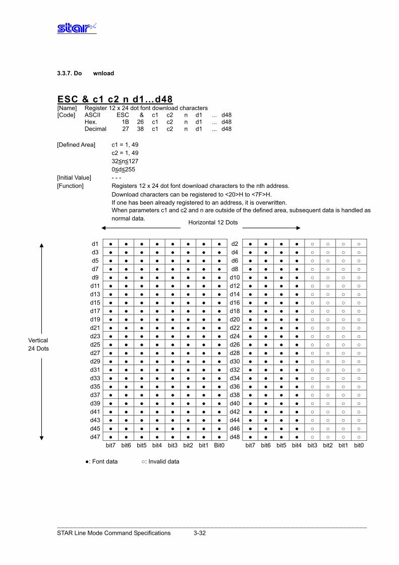
ESC & c1 c2 n d1…d48 [Name] Register 12 x 24 dot font download characters [Code] ASCII ESC & c1 c2 n d1 ... d48 Hex. 1B 26 c1 c2 n d1 ... d48 Decimal 27 38 c1 c2 n d1 ... d48 [Defined Area] c1 = 1, 49 c2 = 1, 49 32≤n≤127 0≤d≤255 [Initial Value] - - - [Function] Registers 12 x 24 dot font download characters to the nth address. Download characters can be registered to <20>H to <7F>H. If one has been already registered to an address, it is overwritten. When parameters c1 and c2 and n are outside of the defined area, subsequent data is handled as
normal data.
d1 ● ● ● ● ● ● ● ● d2 ● ● ● ● ○ ○ ○ ○d3 ● ● ● ● ● ● ● ● d4 ● ● ● ● ○ ○ ○ ○d5 ● ● ● ● ● ● ● ● d6 ● ● ● ● ○ ○ ○ ○d7 ● ● ● ● ● ● ● ● d8 ● ● ● ● ○ ○ ○ ○d9 ● ● ● ● ● ● ● ● d10 ● ● ● ● ○ ○ ○ ○d11 ● ● ● ● ● ● ● ● d12 ● ● ● ● ○ ○ ○ ○d13 ● ● ● ● ● ● ● ● d14 ● ● ● ● ○ ○ ○ ○d15 ● ● ● ● ● ● ● ● d16 ● ● ● ● ○ ○ ○ ○d17 ● ● ● ● ● ● ● ● d18 ● ● ● ● ○ ○ ○ ○d19 ● ● ● ● ● ● ● ● d20 ● ● ● ● ○ ○ ○ ○d21 ● ● ● ● ● ● ● ● d22 ● ● ● ● ○ ○ ○ ○d23 ● ● ● ● ● ● ● ● d24 ● ● ● ● ○ ○ ○ ○d25 ● ● ● ● ● ● ● ● d26 ● ● ● ● ○ ○ ○ ○d27 ● ● ● ● ● ● ● ● d28 ● ● ● ● ○ ○ ○ ○d29 ● ● ● ● ● ● ● ● d30 ● ● ● ● ○ ○ ○ ○d31 ● ● ● ● ● ● ● ● d32 ● ● ● ● ○ ○ ○ ○d33 ● ● ● ● ● ● ● ● d34 ● ● ● ● ○ ○ ○ ○d35 ● ● ● ● ● ● ● ● d36 ● ● ● ● ○ ○ ○ ○d37 ● ● ● ● ● ● ● ● d38 ● ● ● ● ○ ○ ○ ○d39 ● ● ● ● ● ● ● ● d40 ● ● ● ● ○ ○ ○ ○d41 ● ● ● ● ● ● ● ● d42 ● ● ● ● ○ ○ ○ ○d43 ● ● ● ● ● ● ● ● d44 ● ● ● ● ○ ○ ○ ○d45 ● ● ● ● ● ● ● ● d46 ● ● ● ● ○ ○ ○ ○d47 ● ● ● ● ● ● ● ● d48 ● ● ● ● ○ ○ ○ ○
bit7 bit6 bit5 bit4 bit3 bit2 bit1 Bit0 bit7 bit6 bit5 bit4 bit3 bit2 bit1 bit0 ●: Font data ○: Invalid data
Horizontal 12 Dots
Vertical 24 Dots
ESC & c1 c2 n [Name] Delete 12 x 24 dot font download characters [Code] ASCII ESC & c1 c2 n Hex. 1B 26 c1 c2 n Decimal 27 38 c1 c2 n [Defined Area] c1 = 1, 49 c2 = 0, 48 32≤n≤127 [Initial Value] - - - [Function] Deletes 12 x 24 dot font download characters registered to the nth address.
ESC % n [Name] Specifies/cancels ANK download characters [Code] ASCII ESC % n Hex. 1B 25 n Decimal 27 37 n [Defined Area] n=0, 1, 48, 49 [Initial Value] ANK download characters cancelled [Function] Specifies/cancels ANK download characters
n Download characters 0, 48 Cancels ANK download characters 1, 49 Specifies ANK download characters
<Print example of ANK download characters> 1. ANK download character register (ESC & c1 c2 n d1…d48) 2. Specify ANK download characters (ESC % n (n = 1)) 3. Prints ANK download characters
――――――――――――――――――――――――――――――――――――――――――――――――――――――――――――――――――――――――――――― STAR Line Mode Command Specifications 3-33
3.3.8. Bit Image Graphics
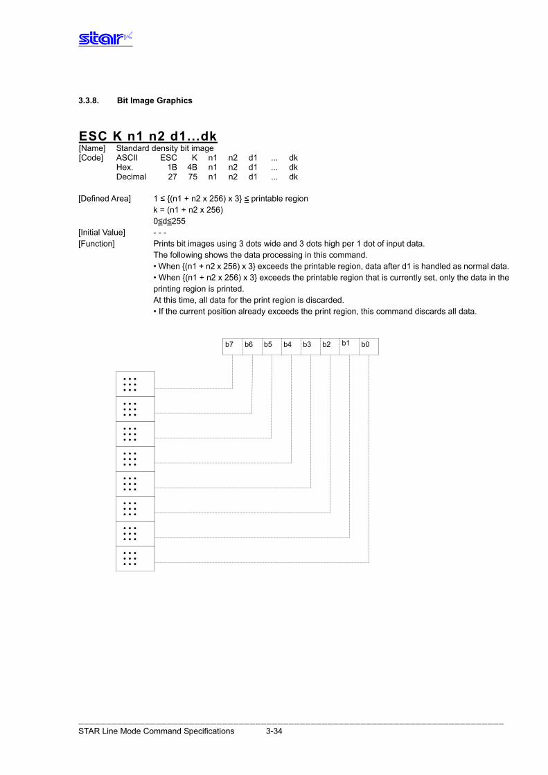
ESC K n1 n2 d1...dk [Name] Standard density bit image [Code] ASCII ESC K n1 n2 d1 ... dk Hex. 1B 4B n1 n2 d1 ... dk Decimal 27 75 n1 n2 d1 ... dk [Defined Area] 1 ≤ {(n1 + n2 x 256) x 3} ≤ printable region k = (n1 + n2 x 256) 0≤d≤255 [Initial Value] - - - [Function] Prints bit images using 3 dots wide and 3 dots high per 1 dot of input data. The following shows the data processing in this command. • When {(n1 + n2 x 256) x 3} exceeds the printable region, data after d1 is handled as normal data. • When {(n1 + n2 x 256) x 3} exceeds the printable region that is currently set, only the data in the
printing region is printed. At this time, all data for the print region is discarded. • If the current position already exceeds the print region, this command discards all data.
b7 b6 b5 b4 b3 b2 b1 b0
• • • • • • • • • • • • • • • • • • • • • • • • • • • • • • • • • • • • • • • • • • • • • • • • • • • • • • • • • • • • • • • • • • • • • • • •
――――――――――――――――――――――――――――――――――――――――――――――――――――――――――――――――――――――――――――― STAR Line Mode Command Specifications 3-34
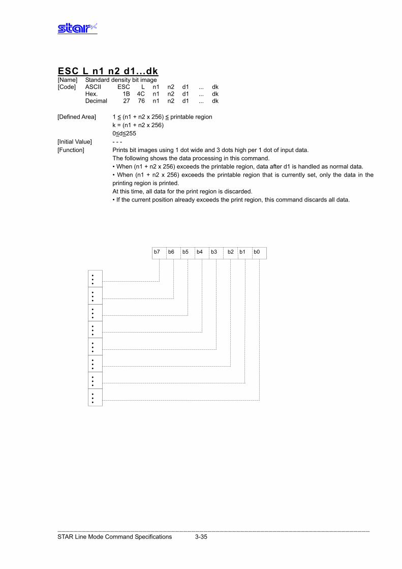
ESC L n1 n2 d1...dk [Name] Standard density bit image [Code] ASCII ESC L n1 n2 d1 ... dk Hex. 1B 4C n1 n2 d1 ... dk Decimal 27 76 n1 n2 d1 ... dk [Defined Area] 1 ≤ (n1 + n2 x 256) ≤ printable region k = (n1 + n2 x 256) 0≤d≤255 [Initial Value] - - - [Function] Prints bit images using 1 dot wide and 3 dots high per 1 dot of input data. The following shows the data processing in this command. • When (n1 + n2 x 256) exceeds the printable region, data after d1 is handled as normal data. • When (n1 + n2 x 256) exceeds the printable region that is currently set, only the data in the
printing region is printed. At this time, all data for the print region is discarded. • If the current position already exceeds the print region, this command discards all data.
b7 b6 b5 b4 b3 b2 b1 b0
• • •
•
• •
• • • • • • •
• • •
• • •
• • •
• • •
――――――――――――――――――――――――――――――――――――――――――――――――――――――――――――――――――――――――――――― STAR Line Mode Command Specifications 3-35
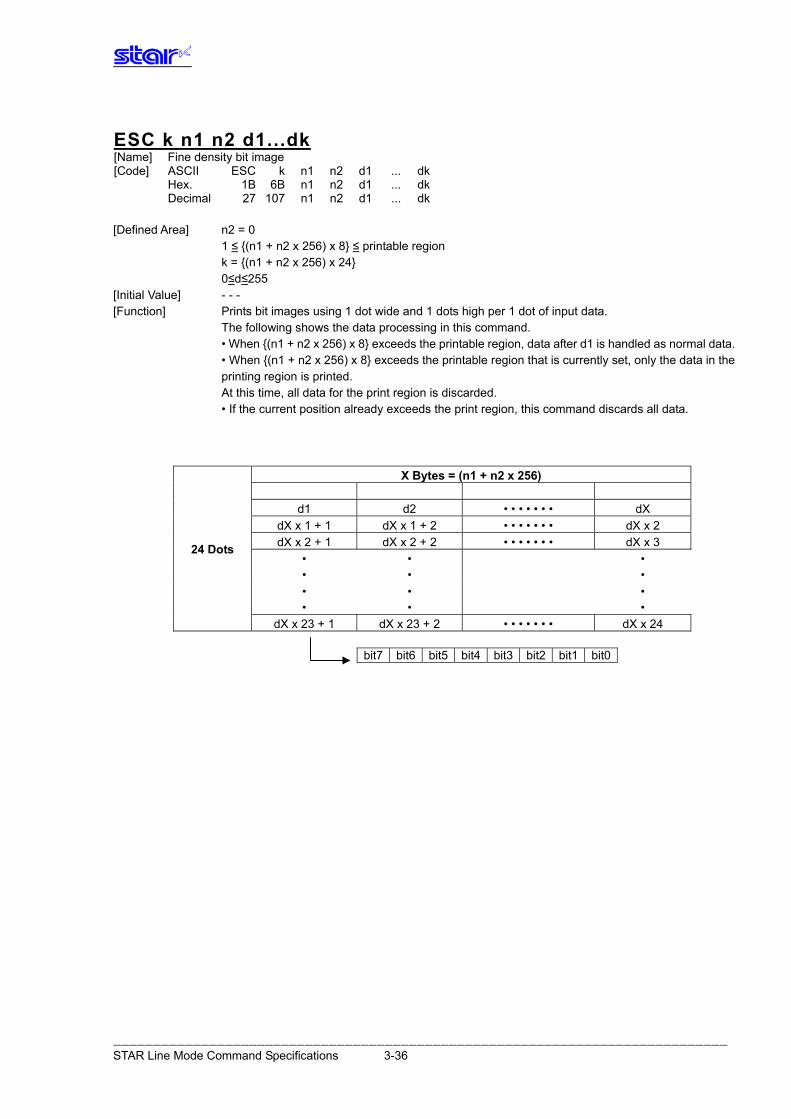
ESC k n1 n2 d1...dk [Name] Fine density bit image [Code] ASCII ESC k n1 n2 d1 ... dk Hex. 1B 6B n1 n2 d1 ... dk Decimal 27 107 n1 n2 d1 ... dk [Defined Area] n2 = 0 1 ≤ {(n1 + n2 x 256) x 8} ≤ printable region k = {(n1 + n2 x 256) x 24} 0≤d≤255 [Initial Value] - - - [Function] Prints bit images using 1 dot wide and 1 dots high per 1 dot of input data. The following shows the data processing in this command. • When {(n1 + n2 x 256) x 8} exceeds the printable region, data after d1 is handled as normal data. • When {(n1 + n2 x 256) x 8} exceeds the printable region that is currently set, only the data in the
printing region is printed. At this time, all data for the print region is discarded. • If the current position already exceeds the print region, this command discards all data.
X Bytes = (n1 + n2 x 256)
d1 d2 • • • • • • • dX dX x 1 + 1 dX x 1 + 2 • • • • • • • dX x 2 dX x 2 + 1 dX x 2 + 2 • • • • • • • dX x 3
• •
• •
• •
24 Dots
• • • •
• •
dX x 23 + 1 dX x 23 + 2 • • • • • • • dX x 24
bit7 bit6 bit5 bit4 bit3 bit2 bit1 bit0
――――――――――――――――――――――――――――――――――――――――――――――――――――――――――――――――――――――――――――― STAR Line Mode Command Specifications 3-36
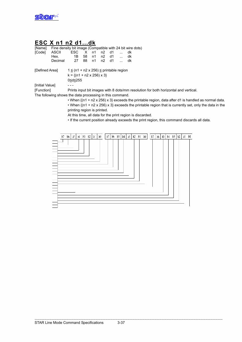
ESC X n1 n2 d1...dk [Name] Fine density bit image (Compatible with 24 bit wire dots) [Code] ASCII ESC X n1 n2 d1 ... dk Hex. 1B 58 n1 n2 d1 ... dk Decimal 27 88 n1 n2 d1 ... dk [Defined Area] 1 ≤ (n1 + n2 x 256) ≤ printable region k = {(n1 + n2 x 256) x 3} 0≤d≤255 [Initial Value] - - - [Function] Prints input bit images with 8 dots/mm resolution for both horizontal and vertical. The following shows the data processing in this command. • When {(n1 + n2 x 256) x 3} exceeds the printable region, data after d1 is handled as normal data. • When {(n1 + n2 x 256) x 3} exceeds the printable region that is currently set, only the data in the
printing region is printed. At this time, all data for the print region is discarded. • If the current position already exceeds the print region, this command discards all data.
――――――――――――――――――――――――――――――――――――――――――――――――――――――――――――――――――――――――――――― STAR Line Mode Command Specifications 3-37
3.3.9. Logo
ESC FS q n [x11 x12 y11 y12 d1. . .dk]1. . . [xn1 xn2 yn1 yn2 d1. . .dk]n [Name] Register logo [Code] ASCII ESC FS q n [x11 x12 y11 y12 d1 ... dk]1 ... [xn1 xn2 yn1 yn2 d1 ... dk]n Hex. 1B 1C 71 n [x11 x12 y11 y12 d1 ... dk]1 ... [xn1 xn2 yn1 yn2 d1 ... dk]n Decimal 27 28 113 n [x11 x12 y11 y12 d1 ... dk]1 ... [xn1 xn2 yn1 yn2 d1 ... dk]n [Defined Area] 1≤n≤255 0≤xn1≤255, 0≤xn2≤3 1≤(xn1 + xn2 x 256)≤1023 0≤yn1≤255, 0≤yn2≤1 1≤yn1 + yn2 x 256)≤288 0≤d≤255 k = {(xn1 + xn2 x 256) x (yn1 + yn2 x 256) x 8} [Initial Value] - - - [Function] Parameter details • n: Specifies registered logo count • xn1, xn2: Horizontal size of registered logo {(xn1 + xn2 x 256) x 8} dots • yn1, yn2: Vertical size of registered logo {(yn1 + yn2 x 256) x 8} dots • d: Registered logo data • k: Logo data count This command should be specified at the top of the line. When the first parameter is determined to be free of error, the printer starts processing this
command. When logo register processing starts, all previously defined data is deleted. (It is not possible to reregister a portion of a plurality of defined logo data.) Logo registration numbers are defined in rising order from 1.
If the defined area specified by the parameter is not empty, or if there is an error in the parameter specification, register processing is aborted. (The pre-registered and complete data is effective.)
The printer should be initialized if logo registration is completed or register processing is aborted. If an error occurs while performing register processing (the time from when the first parameter is
OK until the printer initialization is completed after registering a logo), error processing, mechanical operation and status processing cannot be performed.
The relationships between input data and the actual print are shown on the next page.
――――――――――――――――――――――――――――――――――――――――――――――――――――――――――――――――――――――――――――― STAR Line Mode Command Specifications 3-38
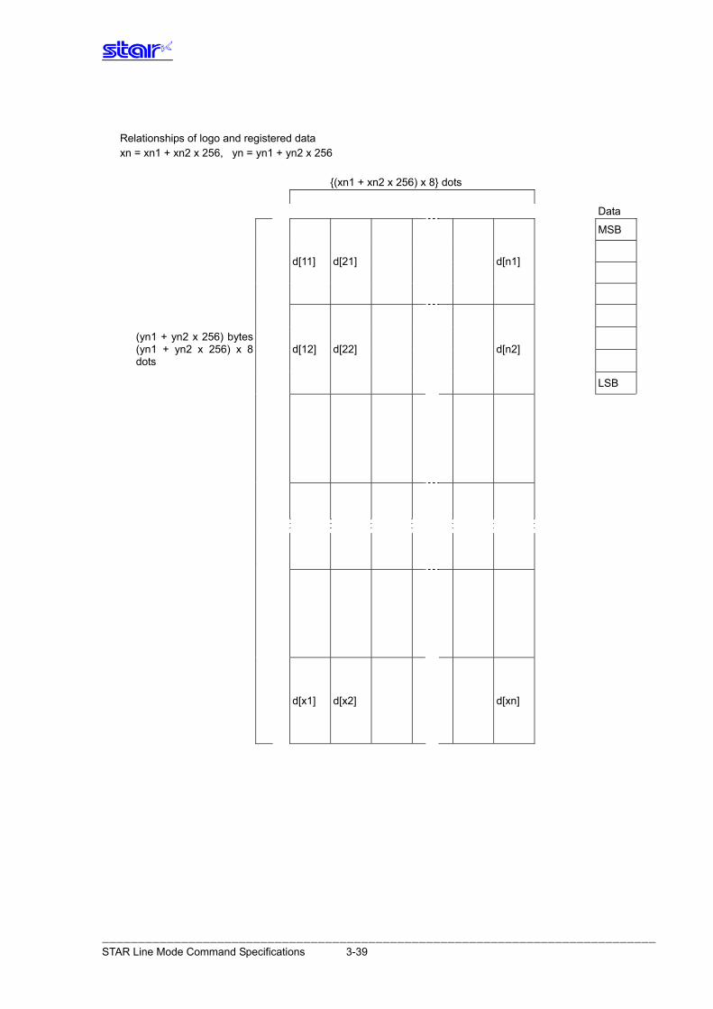
Relationships of logo and registered data xn = xn1 + xn2 x 256, yn = yn1 + yn2 x 256 {(xn1 + xn2 x 256) x 8} dots
Data
MSB
d[11] d[21] d[n1]
(yn1 + yn2 x 256) bytes (yn1 + yn2 x 256) x 8 dots
d[12] d[22] d[n2]
LSB
d[x1] d[x2] d[xn]
――――――――――――――――――――――――――――――――――――――――――――――――――――――――――――――――――――――――――――― STAR Line Mode Command Specifications 3-39
ESC FS p n m [Name] Print logo [Code] ASCII ESC FS p n m Hex. 1B 1C 70 n m Decimal 27 28 112 n m [Defined Area] 1≤n≤255 0≤m≤3 48≤m≤51 (”0”≤m≤”3”) [Initial Value] - - - [Function] Prints the logo of registration number n registered using the logo registration command (ESC FS q)
according to the print mode m.
m Logo print mode 0, 48 Normal mode 1, 49 Double wide mode 2, 50 Double high mode 3, 51 Double high/wide mode
If there is unprinted data in the line buffer, this command is executed after printing that data.
Therefore, it is not possible to print with other data in the same line (characters, bit images, bar codes).
Form feed obeys the vertical print size of the logo. If the logo horizontal print size exceeds the horizontal print region, the portion exceeding the area
is not printed. Logos are printed according to the following command settings. • Left margin (ESC I n) • Right margin (ESC Q n) • Position alignment (ESC GS a n) • Absolute position movement (ESC GS A n1 n2) • Relative position movement (ESC GS R n1 n2) • Upside-down printing (SI) Invalid in page mode.
ESC RS L m [Name] Spec. A Print logo in batch Spec. B Batch control of registered logos [Code] ASCII ESC RS L m Hex. 1B 1E 4C m Decimal 27 30 76 m [Defined Area] Spec. A 0 ≤ m ≤ 3 48 ≤ m ≤ 51 (“0” ≤ m ≤ “3”) Spec. B 0 ≤ m ≤ 3 48 ≤ m ≤ 51 (“0” ≤ m ≤ “3”),m=255 [Initial Value] - - - [Function] Spec. A Prints all registered logos according to a print mode specified by m. Executes a printer
reset after printing. Spec. B Controls logos as specified by the parameter m. After execution, this resets the printer. Invalid in page mode. Spec. A
m Logo print mode 0, 48 Normal mode 1, 49 Double wide mode 2, 50 Double high mode 3, 51 Double high/wide mode
――――――――――――――――――――――――――――――――――――――――――――――――――――――――――――――――――――――――――――― STAR Line Mode Command Specifications 3-40
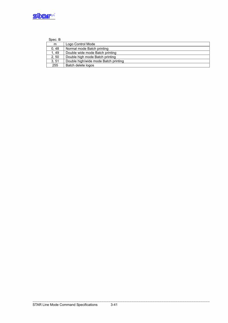
Spec. B
m Logo Control Mode 0, 48 Normal mode Batch printing 1, 49 Double wide mode Batch printing 2, 50 Double high mode Batch printing 3, 51 Double high/wide mode Batch printing 255 Batch delete logos
――――――――――――――――――――――――――――――――――――――――――――――――――――――――――――――――――――――――――――― STAR Line Mode Command Specifications 3-41
3.3.10. Bar Code
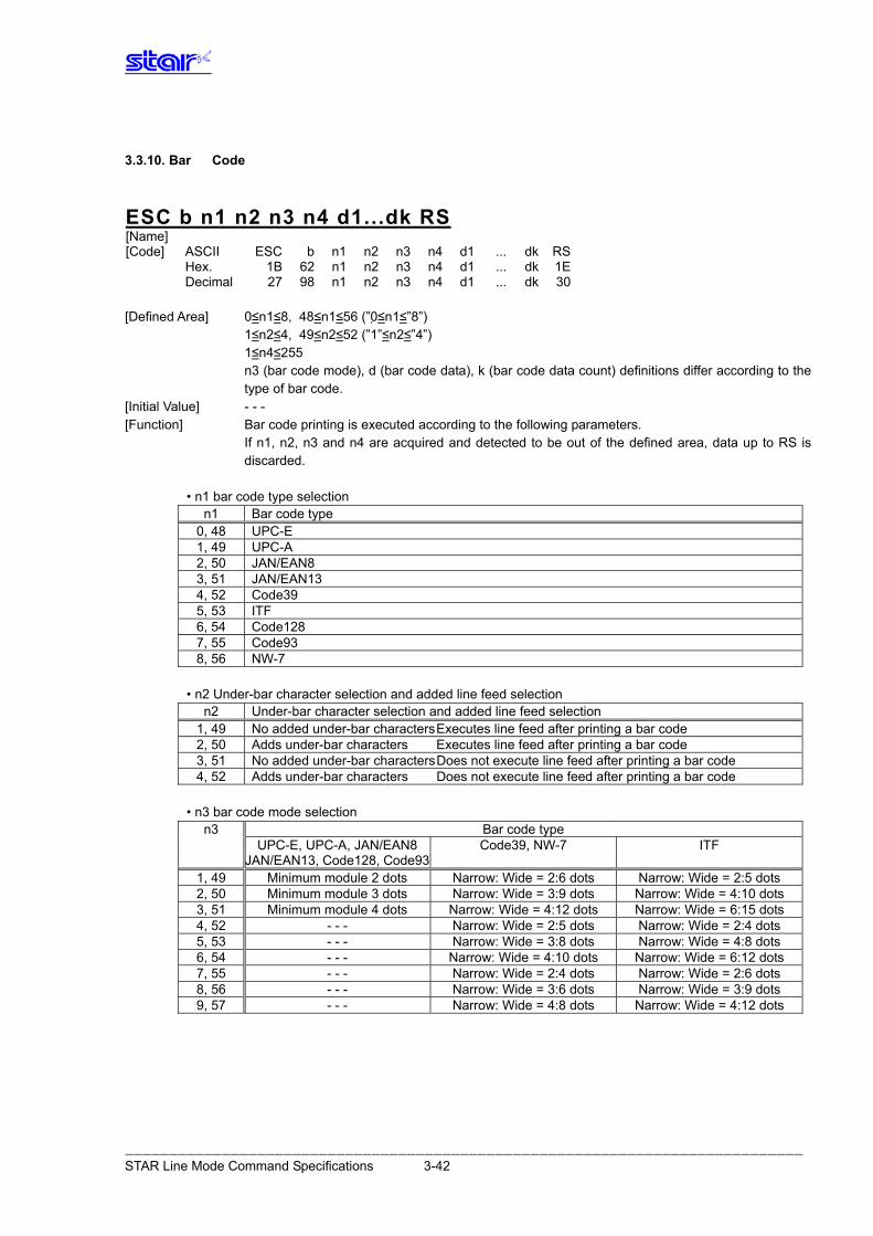
ESC b n1 n2 n3 n4 d1...dk RS [Name] [Code] ASCII ESC b n1 n2 n3 n4 d1 ... dk RS Hex. 1B 62 n1 n2 n3 n4 d1 ... dk 1E Decimal 27 98 n1 n2 n3 n4 d1 ... dk 30 [Defined Area] 0≤n1≤8, 48≤n1≤56 (”0≤n1≤”8”) 1≤n2≤4, 49≤n2≤52 (”1”≤n2≤”4”) 1≤n4≤255 n3 (bar code mode), d (bar code data), k (bar code data count) definitions differ according to the
type of bar code. [Initial Value] - - - [Function] Bar code printing is executed according to the following parameters. If n1, n2, n3 and n4 are acquired and detected to be out of the defined area, data up to RS is
discarded. • n1 bar code type selection
n1 Bar code type 0, 48 UPC-E 1, 49 UPC-A 2, 50 JAN/EAN8 3, 51 JAN/EAN13 4, 52 Code39 5, 53 ITF 6, 54 Code128 7, 55 Code93 8, 56 NW-7
• n2 Under-bar character selection and added line feed selection
n2 Under-bar character selection and added line feed selection 1, 49 No added under-bar characters Executes line feed after printing a bar code 2, 50 Adds under-bar characters Executes line feed after printing a bar code 3, 51 No added under-bar characters Does not execute line feed after printing a bar code 4, 52 Adds under-bar characters Does not execute line feed after printing a bar code
• n3 bar code mode selection
n3 Bar code type UPC-E, UPC-A, JAN/EAN8 Code39, NW-7 ITF JAN/EAN13, Code128, Code93
1, 49 Minimum module 2 dots Narrow: Wide = 2:6 dots Narrow: Wide = 2:5 dots 2, 50 Minimum module 3 dots Narrow: Wide = 3:9 dots Narrow: Wide = 4:10 dots 3, 51 Minimum module 4 dots Narrow: Wide = 4:12 dots Narrow: Wide = 6:15 dots 4, 52 - - - Narrow: Wide = 2:5 dots Narrow: Wide = 2:4 dots 5, 53 - - - Narrow: Wide = 3:8 dots Narrow: Wide = 4:8 dots 6, 54 - - - Narrow: Wide = 4:10 dots Narrow: Wide = 6:12 dots 7, 55 - - - Narrow: Wide = 2:4 dots Narrow: Wide = 2:6 dots 8, 56 - - - Narrow: Wide = 3:6 dots Narrow: Wide = 3:9 dots 9, 57 - - - Narrow: Wide = 4:8 dots Narrow: Wide = 4:12 dots
――――――――――――――――――――――――――――――――――――――――――――――――――――――――――――――――――――――――――――― STAR Line Mode Command Specifications 3-42
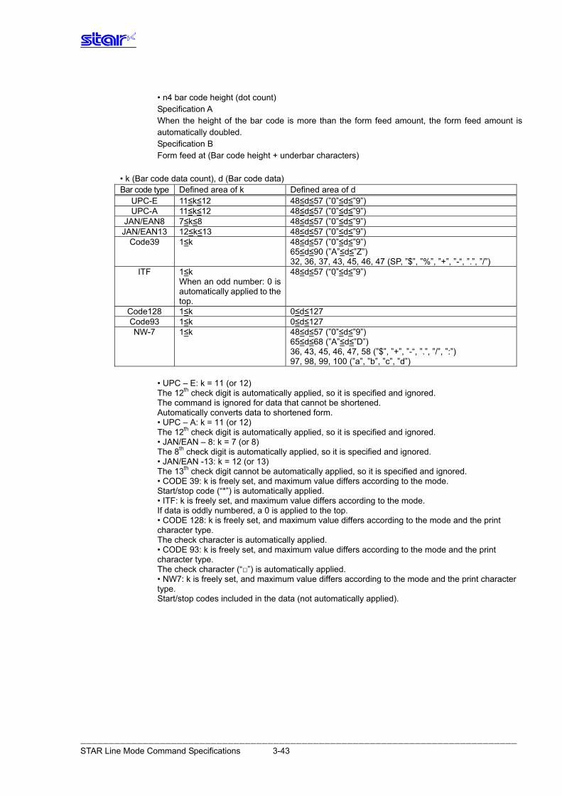
• n4 bar code height (dot count) Specification A When the height of the bar code is more than the form feed amount, the form feed amount is
automatically doubled. Specification B Form feed at (Bar code height + underbar characters) • k (Bar code data count), d (Bar code data)
Bar code type Defined area of k Defined area of d UPC-E 11≤k≤12 48≤d≤57 (”0”≤d≤”9”) UPC-A 11≤k≤12 48≤d≤57 (”0”≤d≤”9”)
JAN/EAN8 7≤k≤8 48≤d≤57 (”0”≤d≤”9”) JAN/EAN13 12≤k≤13 48≤d≤57 (”0”≤d≤”9”)
Code39 1≤k 48≤d≤57 (”0”≤d≤”9”) 65≤d≤90 (”A”≤d≤”Z”) 32, 36, 37, 43, 45, 46, 47 (SP, ”$”, ”%”, ”+”, ”-“, ”.”, ”/”)
ITF 1≤k 48≤When an odd number: 0 is automatically applied to the top.
d≤57 (“0”≤d≤”9”)
Code128 1≤k 0≤d≤127 Code93 1≤k 0≤d≤127 NW-7 1≤k 48≤d≤57 (”0”≤d≤”9”)
65≤d≤68 (”A”≤d≤”D”) 36, 43, 45, 46, 47, 58 (”$”, ”+”, ”-“, ”.”, ”/”, ”:”) 97, 98, 99, 100 (”a”, ”b”, ”c”, ”d”)
• UPC – E: k = 11 (or 12) The 12th check digit is automatically applied, so it is specified and ignored.
The command is ignored for data that cannot be shortened. Automatically converts data to shortened form.
• UPC – A: k = 11 (or 12) The 12th check digit is automatically applied, so it is specified and ignored. • JAN/EAN – 8: k = 7 (or 8) The 8th check digit is automatically applied, so it is specified and ignored. • JAN/EAN -13: k = 12 (or 13) The 13th check digit cannot be automatically applied, so it is specified and ignored. • CODE 39: k is freely set, and maximum value differs according to the mode.
Start/stop code (“*”) is automatically applied. • ITF: k is freely set, and maximum value differs according to the mode.
If data is oddly numbered, a 0 is applied to the top. • CODE 128: k is freely set, and maximum value differs according to the mode and the print
character type. The check character is automatically applied.
• CODE 93: k is freely set, and maximum value differs according to the mode and the print character type. The check character (“□”) is automatically applied.
• NW7: k is freely set, and maximum value differs according to the mode and the print character type.
Start/stop codes included in the data (not automatically applied).
――――――――――――――――――――――――――――――――――――――――――――――――――――――――――――――――――――――――――――― STAR Line Mode Command Specifications 3-43
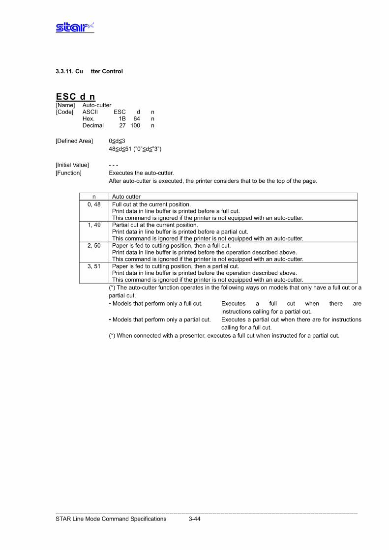
3.3.11. Cu tter Control
ESC d n [Name] Auto-cutter [Code] ASCII ESC d n Hex. 1B 64 n Decimal 27 100 n [Defined Area] 0≤d≤3 48≤d≤51 (”0”≤d≤”3”) [Initial Value] - - - [Function] Executes the auto-cutter. After auto-cutter is executed, the printer considers that to be the top of the page.
n Auto cutter 0, 48 Full cut at the current position.
Print data in line buffer is printed before a full cut. This command is ignored if the printer is not equipped with an auto-cutter.
1, 49 Partial cut at the current position. Print data in line buffer is printed before a partial cut. This command is ignored if the printer is not equipped with an auto-cutter.
2, 50 Paper is fed to cutting position, then a full cut. Print data in line buffer is printed before the operation described above. This command is ignored if the printer is not equipped with an auto-cutter.
3, 51 Paper is fed to cutting position, then a partial cut. Print data in line buffer is printed before the operation described above. This command is ignored if the printer is not equipped with an auto-cutter.
(*) The auto-cutter function operates in the following ways on models that only have a full cut or a partial cut.
• Models that perform only a full cut. Executes a full cut when there are instructions calling for a partial cut.
• Models that perform only a partial cut. Executes a partial cut when there are for instructions calling for a full cut.
(*) When connected with a presenter, executes a full cut when instructed for a partial cut.
――――――――――――――――――――――――――――――――――――――――――――――――――――――――――――――――――――――――――――― STAR Line Mode Command Specifications 3-44
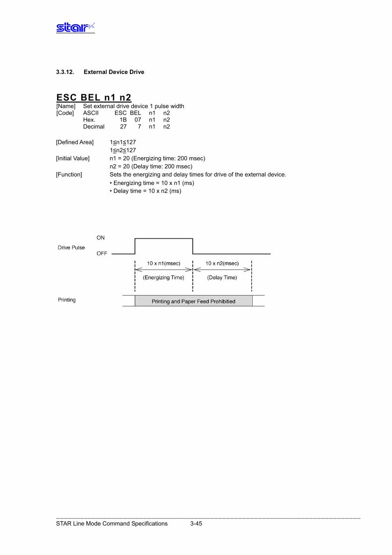
3.3.12. External Device Drive
ESC BEL n1 n2 [Name] Set external drive device 1 pulse width [Code] ASCII ESC BEL n1 n2 Hex. 1B 07 n1 n2 Decimal 27 7 n1 n2 [Defined Area] 1≤n1≤127 1≤n2≤127 [Initial Value] n1 = 20 (Energizing time: 200 msec) n2 = 20 (Delay time: 200 msec) [Function] Sets the energizing and delay times for drive of the external device. • Energizing time = 10 x n1 (ms) • Delay time = 10 x n2 (ms)
――――――――――――――――――――――――――――――――――――――――――――――――――――――――――――――――――――――――――――― STAR Line Mode Command Specifications 3-45
BEL [Name] External device 1 drive instruction [Code] ASCII BEL Hex. 07 Decimal 7 [Defined Area] - - - [Initial Value] - - - [Function] Executes the external device drive conditions set according to the command to set the external
drive device pulse width (ESC BEL n1 n2). As with other commands, it temporarily stores data in the data buffer, then executes in the order
received. External device 1 and external device 2 cannot be executed simultaneously.
FS [Name] External device 1 drive instruction [Code] ASCII FS Hex. 1C Decimal 28 [Defined Area] - - - [Initial Value] - - - [Function] Executes the external device drive conditions set according to the command to set the external
drive device pulse width (ESC BEL n1 n2). As with other commands, it temporarily stores data in the data buffer, then executes in the order
received. External device 1 and external device 2 cannot be executed simultaneously.
――――――――――――――――――――――――――――――――――――――――――――――――――――――――――――――――――――――――――――― STAR Line Mode Command Specifications 3-46
SUB [Name] External device 2 drive instruction [Code] ASCII SUB Hex. 1A Decimal 26 [Defined Area] - - - [Initial Value] - - - [Function] Drives external device 2. The energizing time and delay time for the external device 2 are fixed at 200 ms each. As with other commands, it temporarily stores data in the data buffer, then executes in the order
received. External device 1 and external device 2 cannot be executed simultaneously.
EM [Name] External device 2 drive instruction [Code] ASCII EM Hex. 19 Decimal 25 [Defined Area] - - - [Initial Value] - - - [Function] Drives external device 2. The energizing time and delay time for the external device 2 are fixed at 200 ms each. As with other commands, it temporarily stores data in the data buffer, then executes in the order
received. External device 1 and external device 2 cannot be executed simultaneously.
――――――――――――――――――――――――――――――――――――――――――――――――――――――――――――――――――――――――――――― STAR Line Mode Command Specifications 3-47
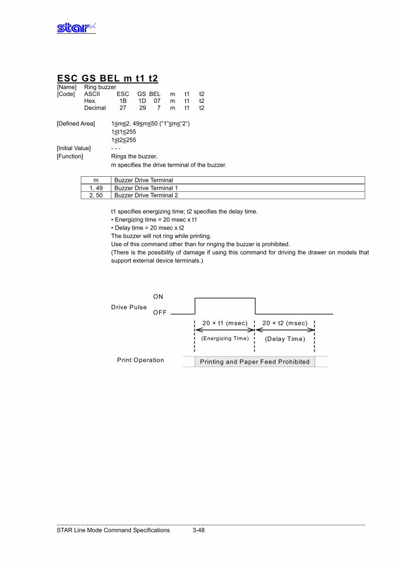
ESC GS BEL m t1 t2 [Name] Ring buzzer [Code] ASCII ESC GS BEL m t1 t2 Hex. 1B 1D 07 m t1 t2 Decimal 27 29 7 m t1 t2 [Defined Area] 1≤m≤2, 49≤m≤50 (”1”≤m≤“2”) 1≤t1≤255 1≤t2≤255 [Initial Value] - - - [Function] Rings the buzzer. m specifies the drive terminal of the buzzer.
m Buzzer Drive Terminal 1, 49 Buzzer Drive Terminal 1 2, 50 Buzzer Drive Terminal 2
t1 specifies energizing time; t2 specifies the delay time. • Energizing time = 20 msec x t1 • Delay time = 20 msec x t2 The buzzer will not ring while printing. Use of this command other than for ringing the buzzer is prohibited. (There is the possibility of damage if using this command for driving the drawer on models that
support external device terminals.)
20 × t2 (msec) 20 × t1 (msec)
Printing and Paper Feed Prohibited
(Energizing Time) (Delay Time)
OFF
ON
Drive Pulse
Print Operation
――――――――――――――――――――――――――――――――――――――――――――――――――――――――――――――――――――――――――――― STAR Line Mode Command Specifications 3-48
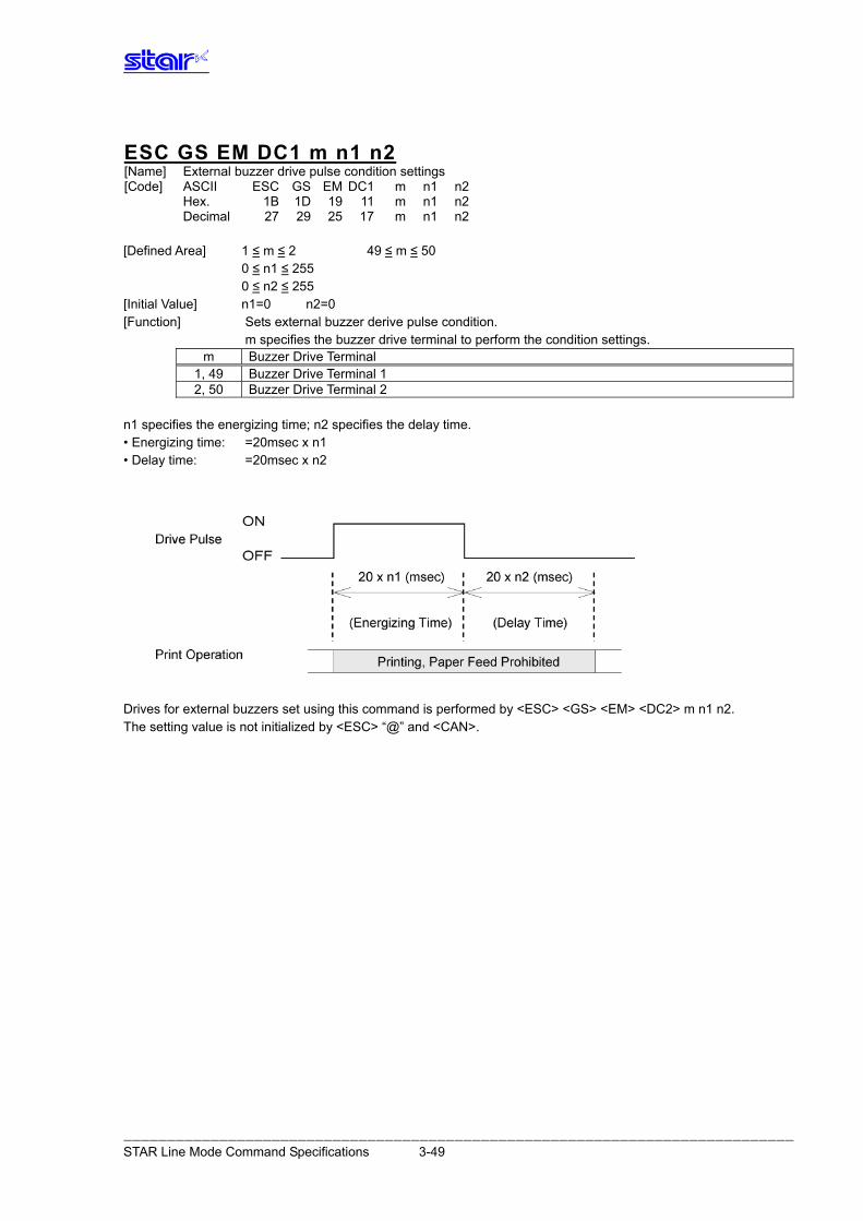
ESC GS EM DC1 m n1 n2 [Name] External buzzer drive pulse condition settings [Code] ASCII ESC GS EM DC1 m n1 n2 Hex. 1B 1D 19 11 m n1 n2 Decimal 27 29 25 17 m n1 n2 [Defined Area] 1 ≤ m ≤ 2 49 ≤ m ≤ 50 0 ≤ n1 ≤ 255 0 ≤ n2 ≤ 255 [Initial Value] n1=0 n2=0 [Function] Sets external buzzer derive pulse condition. m specifies the buzzer drive terminal to perform the condition settings.
m Buzzer Drive Terminal 1, 49 Buzzer Drive Terminal 1 2, 50 Buzzer Drive Terminal 2
n1 specifies the energizing time; n2 specifies the delay time. • Energizing time: =20msec x n1 • Delay time: =20msec x n2
Drives for external buzzers set using this command is performed by <ESC> <GS> <EM> <DC2> m n1 n2. The setting value is not initialized by <ESC> “@” and <CAN>.
――――――――――――――――――――――――――――――――――――――――――――――――――――――――――――――――――――――――――――― STAR Line Mode Command Specifications 3-49
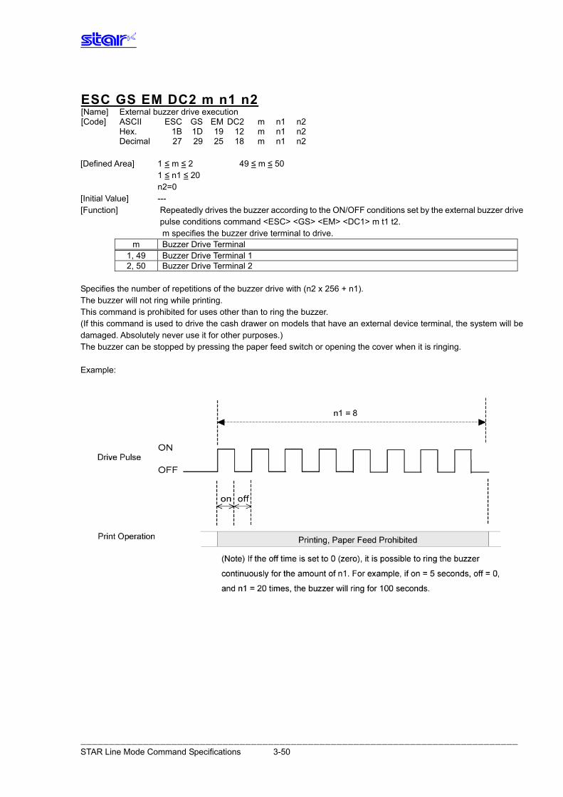
ESC GS EM DC2 m n1 n2 [Name] External buzzer drive execution [Code] ASCII ESC GS EM DC2 m n1 n2 Hex. 1B 1D 19 12 m n1 n2 Decimal 27 29 25 18 m n1 n2 [Defined Area] 1 ≤ m ≤ 2 49 ≤ m ≤ 50 1 ≤ n1 ≤ 20 n2=0 [Initial Value] --- [Function] Repeatedly drives the buzzer according to the ON/OFF conditions set by the external buzzer drive pulse conditions command <ESC> <GS> <EM> <DC1> m t1 t2. m specifies the buzzer drive terminal to drive.
m Buzzer Drive Terminal 1, 49 Buzzer Drive Terminal 1 2, 50 Buzzer Drive Terminal 2
Specifies the number of repetitions of the buzzer drive with (n2 x 256 + n1). The buzzer will not ring while printing. This command is prohibited for uses other than to ring the buzzer. (If this command is used to drive the cash drawer on models that have an external device terminal, the system will be damaged. Absolutely never use it for other purposes.) The buzzer can be stopped by pressing the paper feed switch or opening the cover when it is ringing. Example:
――――――――――――――――――――――――――――――――――――――――――――――――――――――――――――――――――――――――――――― STAR Line Mode Command Specifications 3-50
3.3.13. Prin t Settings
ESC RS d n [Name] Set print density [Code] ASCII ESC RS d n Hex. 1B 1E 64 n Decimal 27 30 100 n [Defined Area] 0≤n≤ 6 48≤n≤57 (”0”≤n≤”6”) [Initial Value] Memory switch setting [Function] Sets print density. This command executes after stopping the printing operation.
When in 2-color mode, only print density for red printing can be set by this command. When in low peak current mode, print density using this command is invalid.
Spec. A. n Print Density Single Color Printing Mode Two Color Printing Mode Red Print Density
Double Resolution Mode (*) Installed print mode depends on the
model. 0, 48 Print density 1.3 Print density 1.2 1, 49 Print density 1.2 Print density 1.2 2, 50 Print density 1.1 Print density 1.0 3, 51 Print density 1.0 Print density 1.0 4, 52 Print density 0.9 Print density 1.0 5, 53 Print density 0.8 Print density 0.8 6, 54 Print density 0.7 Print density 0.8
Spec. B.
n Print Density Single Color Printing Mode 2-color Printing Mode Red Print Density
Double Resolution Mode *1
0, 48 Print density + 3 Print density + 1 1, 49 Print density + 2 Print density + 1 2, 50 Print density + 1 Standard print density (Standard) 3, 51 Standard print density (Standard) Standard print density (Standard) 4, 52 Print density - 1 Standard print density (Standard) 5, 53 Print density - 2 Print density -1 6, 54 Print density - 3 Print density - 1
*1) See the appropriate printer specifications manual for details on the print modes that are available.
――――――――――――――――――――――――――――――――――――――――――――――――――――――――――――――――――――――――――――― STAR Line Mode Command Specifications 3-51
ESC RS r n [Name] Set print speed [Code] ASCII ESC RS r n Hex. 1B 1E 72 n Decimal 27 30 114 n [Defined Area] 0≤n≤3 48≤n≤51 (”0”≤n≤”3”) [Initial Value] Memory switch setting [Function] Sets print speed. This command stops printing to be executed.
Because two-color print mode, low peak current mode, and double resolution mode print in one speed, the speed settings with this command are invalid. This command setting becomes valid when returned from the two-color print mode, low peak current mode, and double resolution mode to the single color print mode. Invalid in page mode.
Spec. A
n Print Speed Single Color Printing Mode Two Color Printing Mode
Low Peak Current Mode Double Resolution
(*) Installed print mode depends on the model.
0, 48 High speed Each print mode speed 1, 49 Mid-speed Each print mode speed 2, 50 Slow speed Each print mode speed 3, 51 Option-speed Each print mode speed
(*) Print speed depends on the model. Spec. B
n Print Speed Single Color Printing Mode Two Color Printing Mode
Low Peak Current Mode Double Resolution
(*) Installed print mode depends on the model.
0, 48 Standard Each print mode speed 1, 49 Mid-speed Each print mode speed 2, 50 Slow speed Each print mode speed 3, 51 High speed Each print mode speed
――――――――――――――――――――――――――――――――――――――――――――――――――――――――――――――――――――――――――――― STAR Line Mode Command Specifications 3-52
3.3.14. Statu s
ESC RS a n [Name] Set status transmission conditions [Code] ASCII ESC RS a n Hex. 1B 1E 61 n Decimal 27 30 97 n [Defined Area] For Specifications A and B 0≤n≤3, 48≤n≤51(”0”≤n≤”3”) For Specification C 0≤n≤3, 48≤n≤51(”0”≤n≤”3”) [Initial Value] Set by DIP switches and memory switches. [Function] Sets the status transmission conditions. See Appendix 2 for details regarding ASB status. Settings of this command are unaffected by the ESC @ command.
See each printer's product specifications manual for details on the DIP SW and memory switch settings. When the printer uses a wireless LAN I/F, this command is ignored. Specification A
n Status transmission conditions 0, 48 ASB invalid 1, 49 ASB valid
Specification B
n Status transmission condition settings 0, 48 ASB invalid 1, 49 ASB valid
Specification C.
n Status transmission conditions 0, 48 ASB Invalid • NSB Invalid 1, 49 ASB Valid • NSB Invalid 2, 50 ASB Invalid • NSB Valid 3, 51 ASB Valid • NSB Valid
――――――――――――――――――――――――――――――――――――――――――――――――――――――――――――――――――――――――――――― STAR Line Mode Command Specifications 3-53
ESC ACK SOH [Name] Real-time printer status (ASB status) [Code] ASCII ESC ACK SOH Hex. 1B 06 01 Decimal 27 6 1 [Defined Area] - - - [Initial Value] - - - [Function] Sends ASB status information to the host. This command is not used when ASB is valid. See Appendix 2, Automatic Status for details regarding ASB status.
ENQ [Name] Real-time printer status (1) [Code] ASCII ENQ Hex. 05 Decimal 5 [Defined Area] - - - [Initial Value] - - - [Function] Sends 1 byte of the following the printer status This command is not used when ASB is valid. See Appendix 2, ENQ Command Status for details regarding status.
EOT [Name] Real-time printer status (2) [Code] ASCII EOT Hex. 04 Decimal 4 [Defined Area] - - - [Initial Value] - - - [Function] Sends 1 byte of the following the printer status This command is not used when ASB is valid. See Appendix 2, EOT Command Status for details regarding status.
ESC ACK CAN [Name] Execute real-time printer reset [Code] ASCII ESC ACK CAN Hexadecimal 1B 06 18 Decimal 27 6 24 [Defined Area] --- [Initial Value] --- [Function] Execute real-time printer reset.
――――――――――――――――――――――――――――――――――――――――――――――――――――――――――――――――――――――――――――― STAR Line Mode Command Specifications 3-54
ETB [Name] Update ASB ETB status [Code] ASCII ETB Hex. 17 Decimal 23 [Defined Area] - - - [Initial Value] - - - [Function] Spec. Aifications Sets the ASB ETB status when reading this command from the reception buffer, then sends ASB.
See Appendix 2, ASB Status for details. Spec. Bifications Sets the ASB ETB status when reading this command from the reception buffer. Then, after
updating the ASB ETB counter, sends the ASB status. See Appendix 2, ASB Status for details. The following outlines the details of processes in this command. (1) Reads ETB command from reception buffer. (2) Waits for printing of the print data before the ETB command to end. (3) Increments the ASB ETB counter by 1 after checking that printing has ended, then sets the ASB
ETB status. (4) Sends ASB (only when ASB is enabled).
• Precautions when using Ethernet When multi-session is valid the ASB (ETB counter) sent by <ETB> is sent to all hosts that are
connected. For that reason, sending ETB from multiple sessions, can cause mis-recognition of the ETB
counter. Therefore, we recommend the <ESC><GS><ETX> commands to confirm the print end counter. See the Command List by Model.
ESC RS E n [Name] Initialize ASB ETB counter and ETB status [Code] ASCII ESC RS E n Hex. 1B 1E 45 n Decimal 27 30 69 n [Defined Area] n = 0 n = 48 (“0”) [Initial Value] ASB ETB counter = 0 [Function] Clears the ASB ETB counter to zero, then clears the ETB status. However, ASB status is not send when clearing the ETB counter to zero using this command. The
ETB counter and ETB status are initialized by the following command, not this command. • Cancel print data and initialize command <CAN>
――――――――――――――――――――――――――――――――――――――――――――――――――――――――――――――――――――――――――――― STAR Line Mode Command Specifications 3-55
ESC GS ETX s n1 n2 [Name] Send print-end counter, initialize [Code] ASCII ESC GS ETX s n1 n2 Hexadecimal 1B 1D 03 s n1 n2 Decimal 27 30 3 s n1 n2 [Defined Area] 0 ≤ s ≤ 4
0 ≤ n1 ≤ 255, 0 ≤ n2 ≤ 255 [Function] This command is run when reading from the reception buffer. Processes the print end counter according to the s parameter.
s Name Function
Sends the current print end counter to the host. 0 Print end counter reference
(Does not wait for print end. Does not count up.) Runs the following operations. (1) Prints data in line buffer, if data exists. (2) Waits until printing ends (motor stops). 1 Print end counter update (3) Updates the print end counter (increments by 1). (4) Sends print end counter to host. Returns the print end counter to its default value (zero clear).
2 Print end counter clear (Does not wait for print end. Does not send the print end counter to the host.
Start document (1) Sets data intake mode 3
n1, n2 = 0 (2) Initialize
(1) Prints data in line buffer, if data exists. End document
(2) Waits until printing ends (motor stops). 4 n1, n2 = 0
(3) Cancels data intake mode
The data formats sent to the host when s = 0 or s =1 are shown below.
<Returned Data Formats> [Code] ASCII ESC GS ETX s n1 n2 [Print end counter] NUL Hexadecima
l 1B 1D 03 s n1 n2 00 [Print end counter]
Decimal 27 30 3 s n1 n2 [Print end counter] 0
* Echoes back the specified contents from the host as is until ESC GS ETX s n1 n2, and then sends the print end counter value and NUL.
When [Print end counter] is 1 byte in length, the initial value is 0x00. When s = 1, increments by 1 each time the command is processed. After 0xFF, returns to 0x00. There is one [Print end counter] in the printer that is unrelated to the n1, n2 values. (There is no counter for the n1, n2 values.)
――――――――――――――――――――――――――――――――――――――――――――――――――――――――――――――――――――――――――――― STAR Line Mode Command Specifications 3-56
(Reference Information) Differences between the ETB command and this command Item ESC GS ETX s n1 n2 ETB Affect on ASB (ETB Status) None Yes ASB occurrence None Yes Affect of ASB valid/invalid setting None Yes Affect of the ESC RS E n command None Yes Status transmission destination in Ethernet
Send only when in the print session (host) that is connected
Send ASB to all sessions (hosts) that are connected
(When multi-sessions is valid) * This print end counter and the ETB counter sent by the ETB command are separate. They have no affect
on each other.
The following shows a communication example of this command. Communication Example 1
Host Transmission Data Printer return data ESC GS ETX 0x00 0x00 0x00 → (Reference
Counter) ESC GS ETX 0x00 0x00 0x00 0x00 0x00 ←Print Data + ESC GS ETX 0x01 0x00 0x00 → (Reference
Update) ESC GS ETX 0x01 0x00 0x00 0x01 0x00 ←Print Data + ESC GS ETX 0x01 0x00 0x00 → (Reference
Update) ESC GS ETX 0x01 0x00 0x00 0x02 0x00 ←Communication Example 2
Host Transmission Data Printer return data ESC GS ETX 0x02 0x02 0x00 (Clear
Counter)
ESC GS ETX 0x00 0x02 0x00 →ESC GS ETX 0x00 0x02 0x00 0x00 0x00 (Reference
Counter) ←
Print Data + ESC GS ETX 0x01 0x02 0x11 → (Reference Update) ESC GS ETX 0x01 0x02 0x11 0x01 0x00 ←
Print Data + ESC GS ETX 0x01 0x02 0x12 → (Reference Update) ESC GS ETX 0x01 0x02 0x12 0x02 0x00 ←
Print Data + ESC GS ETX 0x01 0x02 0x13 → (Reference Update) ESC GS ETX 0x01 0x02 0x13 0x03 0x00 ←
Print Data + ESC GS ETX 0x01 0x02 0x14 → (Reference Update) ESC GS ETX 0x01 0x02 0x14 0x04 0x00 ←
<Example using n1, n2> • For Ethernet: Specify as n1 = host ID, n2 = document number, and check the compatibility of source
information and returned information for the host ID and document ID along with getting the returned print end counter.
• For cases other than Ethernet: Specify n1+n2 x 256 as the document ID and check the compatibility with the document ID in the same way.
• When it is not possible to check compatibility of the source and returned data, fix at n1 = 0, n2 = 0. When s = 3, and s = 4, printer operates as though in data cancel mode. (1) Receive and discard all data being received. (Document start command) (2) Receive and discard only the current page. (Document start command + document end command) If there is an error after receiving the document start command, reception data is received and discarded until the document end command is received when the printer is recovered from the error. If the document end command cannot be recognized, all reception data is destroyed. Timeouts are two seconds. Automatically cancels the data intake mode.
――――――――――――――――――――――――――――――――――――――――――――――――――――――――――――――――――――――――――――― STAR Line Mode Command Specifications 3-57
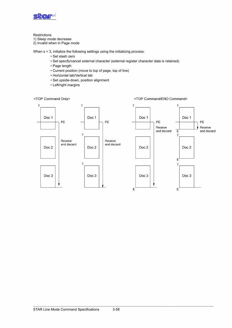
Restrictions 1) Sleep mode decrease 2) Invalid when in Page mode When s = 3, initialize the following settings using the initializing process.
• Set slash zero • Set specify/cancel external character (external register character data is retained) • Page length • Current position (move to top of page, top of line) • Horizontal tab/Vertical tab • Set upside-down, position alignment • Left/right margins
――――――――――――――――――――――――――――――――――――――――――――――――――――――――――――――――――――――――――――― STAR Line Mode Command Specifications 3-58
3.3.15. Kanji characters
ESC p [Name] Specify JIS Kanji character mode [Code] ASCII ESC p Hex. 1B 70 Decimal 27 112 [Defined Area] - - - [Initial Value] JIS Kanji character mode cancelled [Function] Specifies JIS Kanji character mode When in JIS Kanji character mode, character codes are all handled as 2 byte Kanji characters
(First byte: upper code; second byte: lower code). This command is ignored for models not equipped with Japanese and Kanji characters and when
the specification for the location of use is specified as SBCS (single byte countries) by the memory switch. In such a case, this is handled as the ANK font 14 dot pitch specification command.
ESC q [Name] Cancel JIS Kanji character mode [Code] ASCII ESC q Hex. 1B 71 Decimal 27 113 [Defined Area] - - - [Initial Value] JIS Kanji character mode cancelled [Function] Cancel JIS Kanji character mode
――――――――――――――――――――――――――――――――――――――――――――――――――――――――――――――――――――――――――――― STAR Line Mode Command Specifications 3-59
ESC $ n [Name] Specify/cancel Shift JIS Kanji character mode [Code] ASCII ESC $ n Hex. 1B 24 n Decimal 27 36 n [Defined Area] - - - [Initial Value] Memory switch setting [Function] Specifies and cancels the shift JIS Kanji character mode. When in shift JIS Kanji character mode, character codes are all handled as 2 byte Kanji characters
(First byte: upper code; second byte: lower code). This command is ignored for models not equipped with Japanese and Kanji characters and when
the specification for the location of use is specified as SBCS (single byte countries) by the memory switch.
n Shift JIS Kanji character mode 0, 48 Cancels shift JIS Kanji character mode 1, 49 Specifies shift JIS Kanji character mode
――――――――――――――――――――――――――――――――――――――――――――――――――――――――――――――――――――――――――――― STAR Line Mode Command Specifications 3-60
ESC s n1 n2 [Name] Set 2 byte Kanji character left/right spaces [Code] ASCII ESC s n1 n2 Hex. 1B 73 n1 n2 Decimal 27 115 n1 n2 [Defined Area] 0≤n1≤7 48≤n1≤55 (”0”≤n1≤”7”) 0≤n2≤15 48≤n2≤57 (”0”≤n2≤”9”) 65≤n2≤70 (”A”≤n2≤”F”) [Initial Value] Memory switch setting [Function] Adds n1 dots left space amount and n2 dots right space amount to Kanji characters. The Kanji character width is "left space amount” + "Kanji font dot count” + "right space amount.” (See the information on character specifications in the appropriate printer specifications manual for details on the Kanji font dot count.)
This command is ignored for models not equipped with Chinese fonts (for overseas) and when the specification for the location of use is specified as SBCS (single byte countries) by the memory switch.
Standard mode and page mode can be set independently of each other.
ESC t n1 n2 [Name] Set 1 byte Kanji character left/right spaces [Code] ASCII ESC t n1 n2 Hex. 1B 74 n1 n2 Decimal 27 116 n1 n2 [Defined Area] 0≤n1≤7 48≤n1≤55 (”0”≤n1≤”7”) 0≤n2≤15 48≤n2≤57 (”0”≤n2≤”9”) 65≤n2≤70 (”A”≤n2≤”F”) [Initial Value] Memory switch setting [Function] Adds n1 dots left space amount and n2 dots right space amount to single-byte Kanji characters. The single-byte Kanji character width is "left space amount” + "single-byte Kanji font dot count” + "right space amount.” (See the information on character specifications in the appropriate printer specifications manual for details on the single-byte Kanji font dot count.)
This command is ignored for models not equipped with Chinese fonts (for overseas) and when the specification for the location of use is specified as SBCS (single byte countries) by the memory switch.
Standard mode and page mode can be set independently of each other.
――――――――――――――――――――――――――――――――――――――――――――――――――――――――――――――――――――――――――――― STAR Line Mode Command Specifications 3-61
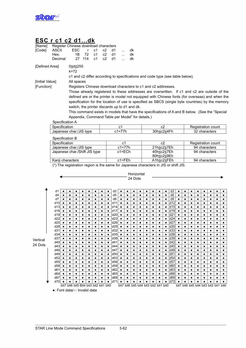
――――――――――――――――――――――――――――――――――――――――――――――――――――――――――――――――――――――――――――― STAR Line Mode Command Specifications 3-62
ESC r c1 c2 d1...dk [Name] Register Chinese download characters [Code] ASCII ESC r c1 c2 d1 ... dk Hex. 1B 72 c1 c2 d1 ... dk Decimal 27 114 c1 c2 d1 ... dk [Defined Area] 0≤d≤255 k=72 c1 and c2 differ according to specifications and code type (see table below). [Initial Value] All spaces [Function] Registers Chinese download characters to c1 and c2 addresses. Those already registered to these addresses are overwritten. If c1 and c2 are outside of the
defined are or the printer is model not equipped with Chinese fonts (for overseas) and when the specification for the location of use is specified as SBCS (single byte countries) by the memory switch, the printer discards up to d1 and dk.
This command exists in models that have the specifications of A and B below. (See the “Special Appendix, Command Table per Model” for details.)
Specification A Specification c1 c2 Registration count Japanese char./JIS type c1=77h 30h≤c2≤4Fh 32 characters
Specification B
Specification c1 c2 Registration count Japanese char./JIS type c1=77h 21h≤c2≤7Eh 94 characters Japanese char./Shift JIS type c1=ECh 40h≤c2≤7Eh
80h≤c2≤9Eh 94 characters
Kanji characters c1=FEh A1h≤c2≤FEh 94 characters (*) The registration region is the same for Japanese characters in JIS or shift JIS.
d1 ● ● ● ● ● ● ● ● d2 ● ● ● ● ● ● ● ● d3 ● ● ● ● ● ● ● ●d4 ● ● ● ● ● ● ● ● d5 ● ● ● ● ● ● ● ● d6 ● ● ● ● ● ● ● ●d7 ● ● ● ● ● ● ● ● d8 ● ● ● ● ● ● ● ● d9 ● ● ● ● ● ● ● ●
d10 ● ● ● ● ● ● ● ● d11 ● ● ● ● ● ● ● ● d12 ● ● ● ● ● ● ● ●d13 ● ● ● ● ● ● ● ● d14 ● ● ● ● ● ● ● ● d15 ● ● ● ● ● ● ● ●d16 ● ● ● ● ● ● ● ● d17 ● ● ● ● ● ● ● ● d18 ● ● ● ● ● ● ● ●d19 ● ● ● ● ● ● ● ● d20 ● ● ● ● ● ● ● ● d21 ● ● ● ● ● ● ● ●d22 ● ● ● ● ● ● ● ● d23 ● ● ● ● ● ● ● ● d24 ● ● ● ● ● ● ● ●d25 ● ● ● ● ● ● ● ● d26 ● ● ● ● ● ● ● ● d27 ● ● ● ● ● ● ● ●d28 ● ● ● ● ● ● ● ● d29 ● ● ● ● ● ● ● ● d30 ● ● ● ● ● ● ● ●d31 ● ● ● ● ● ● ● ● d32 ● ● ● ● ● ● ● ● d33 ● ● ● ● ● ● ● ●d34 ● ● ● ● ● ● ● ● d35 ● ● ● ● ● ● ● ● d36 ● ● ● ● ● ● ● ●d37 ● ● ● ● ● ● ● ● d38 ● ● ● ● ● ● ● ● d39 ● ● ● ● ● ● ● ●d40 ● ● ● ● ● ● ● ● d41 ● ● ● ● ● ● ● ● d42 ● ● ● ● ● ● ● ●d43 ● ● ● ● ● ● ● ● d44 ● ● ● ● ● ● ● ● d45 ● ● ● ● ● ● ● ●d46 ● ● ● ● ● ● ● ● d47 ● ● ● ● ● ● ● ● d48 ● ● ● ● ● ● ● ●d49 ● ● ● ● ● ● ● ● d50 ● ● ● ● ● ● ● ● d51 ● ● ● ● ● ● ● ●d52 ● ● ● ● ● ● ● ● d53 ● ● ● ● ● ● ● ● d54 ● ● ● ● ● ● ● ●d55 ● ● ● ● ● ● ● ● d56 ● ● ● ● ● ● ● ● d57 ● ● ● ● ● ● ● ●d58 ● ● ● ● ● ● ● ● d59 ● ● ● ● ● ● ● ● d60 ● ● ● ● ● ● ● ●d61 ● ● ● ● ● ● ● ● d62 ● ● ● ● ● ● ● ● d63 ● ● ● ● ● ● ● ●d64 ● ● ● ● ● ● ● ● d65 ● ● ● ● ● ● ● ● d66 ● ● ● ● ● ● ● ●d67 ● ● ● ● ● ● ● ● d68 ● ● ● ● ● ● ● ● d69 ● ● ● ● ● ● ● ●d70 ● ● ● ● ● ● ● ● d71 ● ● ● ● ● ● ● ● d72 ● ● ● ● ● ● ● ●
bit7 bit6 bit5 Bit4 bit3 bit2 bit1 bit0 bit7 bit6 bit5 bit4 bit3 bit2 bit1 bit0 bit7 bit6 bit5 bit4 bit3 bit2 bit1 bit0 ●: Font data/○: Invalid data
Horizontal 24 Dots
Vertical 24 Dots
3.3.16. Oth ers
CAN [Name] Cancel print data and initialize commands [Code] ASCII CAN Hex. 18 Decimal 24 [Defined Area] - - - [Initial Value] - - - [Function] When the reception buffer and line buffer are cleared, the set commands are initialized. Immediately executed not when taking out from the reception buffer, but when received from the
host. DIPSW re-reading is not performed. The following shows the specifications that are not initialized by this command. • Set print density • Set print speed • Set 2 color print mode • Print color in 2 color print mode • External device drive condition
――――――――――――――――――――――――――――――――――――――――――――――――――――――――――――――――――――――――――――― STAR Line Mode Command Specifications 3-63
ESC @ [Name] Command initialization [Code] ASCII ESC @ Hex. 1B 40 Decimal 27 64 [Defined Area] - - - [Initial Value] - - - [Function] Initializes each command after printing data in the line buffer. However, printers with memory switch settings are initialized to the memory switch settings. DIPSW re-reading is not performed. • ANK characters, Kanji character adornment, expansion • Kanji character mode • ANK right space • Kanji character left/right spaces • Character pitch • International characters • Code page • Set slash zero • Set specify/cancel external character (external register character data is retained) • Page length • Current position (move to top of page, top of line) • Horizontal tab/Vertical tab • Line feed amount • Set upside-down, position alignment • Left/right margins The following shows the specifications that are not initialized by this command. • Set print density • Set print speed • Set 2 color print mode • Print color in 2 color print mode • External device drive condition
――――――――――――――――――――――――――――――――――――――――――――――――――――――――――――――――――――――――――――― STAR Line Mode Command Specifications 3-64
――――――――――――――――――――――――――――――――――――――――――――――――――――――――――――――――――――――――――――― STAR Line Mode Command Specifications 3-65
ESC GS # m N n1 n2 n3 n4 LF NUL [Name] Set memory switch [Code] ASCII ESC GS # m N n1 n2 n3 n4 LF NUL Hex. 1B 1D 23 m N n1 n2 n3 n4 0A 00 Decimal 27 29 35 m N n1 n2 n3 n4 10 0 [Defined Area] 48 ≤ n1 ≤ 57 (”0” ≤ n1 ≤ “9”), 65 ≤ n1 ≤ 70 (”A” ≤ n1 ≤ “F”), 97 ≤ n1 ≤ 102 (“a” ≤ n1 ≤ “f”)
48 ≤ n2 ≤ 57 (”0” ≤ n2 ≤ “9”), 65 ≤ n2 ≤ 70 (”A” ≤ n2 ≤ “F”), 97 ≤ n2 ≤ 102 (“a” ≤ n2 ≤ “f”) 48 ≤ n3 ≤ 57 (”0” ≤ n3 ≤ “9”), 65 ≤ n3 ≤ 70 (”A” ≤ n3 ≤ “F”), 97 ≤ n3 ≤ 102 (“a” ≤ n3 ≤ “f”) 48 ≤ n4 ≤ 57 (”0” ≤ n4 ≤ “9”), 65 ≤ n4 ≤ 70 (”A” ≤ n4 ≤ “F”), 97 ≤ n4 ≤ 102 (“a” ≤ n4 ≤ “f”)
Spec. A
m = 87, 84, 44, 43, 45, 64 (m = “W”, “T”, “,”, “+”, “-”, “@”)
48 ≤ N ≤ 57 (”0” ≤ N ≤ “9”), 65 ≤ N ≤ (*)70 (”A” ≤ N ≤ (*)“F”), 97 ≤ N ≤ (*) 102, (“a” ≤ N ≤ (*) (*) “f”) Spec. B
m = 87, 84, 44, 43, 45, 64 (m = “W”, “T”, “,”, “+”, “-”, “@”)
48 ≤ N ≤ 57 (”0” ≤ N ≤ “9”), 65 ≤ N ≤ (*)70 (”A” ≤ N ≤ (*)“F”), 97 ≤ N ≤ (*) 102, (“a” ≤ N ≤ (*) (*) “f”) N = 85 (N = “U”) User defined area
Spec. C
m = 87, 84, 44, 43, 45, 64, 42 (m = “W”, “T”, “,”, “+”, “-”, “@”, “*”)
48 ≤ N ≤ 57 (”0” ≤ N ≤ “9”), 65 ≤ N ≤ (*)70 (”A” ≤ N ≤ (*)“F”), 97 ≤ N ≤ (*) 102, (“a” ≤ N ≤ (*) (*) “f”) N = 85 (N = “U”) User defined area
(*) The memory switch defined area differs according to the model. [Initial Value] - - - [Function] Sends command to write after defining memory switch using the definition command specified by
the following classes. Memory switch information defined by the command to write is written to the volatile memory. When writing to the volatile memory by the command to write, the printer executes a reset. This command exists in models that have the specifications of A, B and C indicated in the above
defined areas. On models that have specification C, you can load the default settings by specifying m = 42 (*). Models having specifications B can register any 16 bit data by specifying N = 85 (”U”). (See the
“Special Appendix, Command Table per Model” for details per model.)
Functions Class m N n1 n2 n3 n4 Definition data write and reset Write “W” Fixed at “0” Fixed at “0000” Definition data write and reset and self print
Write “T” Fixed at “0” Fixed at “0000”
Data definition (data specification) Definition “, ” N n1 n2 n3 n4 Data definition (specify bit and set) Definition “+” N n1 n2 n3 n4 Data definition (specify bit and clear) Definition “-” N n1 n2 n3 n4 Definition data (all data initialized) Definition “@” Fixed at “0” Fixed at “0000” Definition data (load default settings) Definition “*” Fixed at “0” Fixed at “0000”
• m: Mode selection • N: Memory switch number to specify • n1 n2 n3 n4: Specify data m = (“,”) Specify data m = (“+”) Bit number to set m = (“-“) Bit number to clear
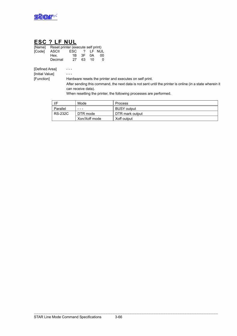
ESC ? LF NUL [Name] Reset printer (execute self print) [Code] ASCII ESC ? LF NUL Hex. 1B 3F 0A 00 Decimal 27 63 10 0 [Defined Area] - - - [Initial Value] - - - [Function] Hardware resets the printer and executes on self print. After sending this command, the next data is not sent until the printer is online (in a state wherein it
can receive data). When resetting the printer, the following processes are performed.
I/F Mode Process Parallel - - - BUSY output RS-232C DTR mode DTR mark output Xon/Xoff mode Xoff output
――――――――――――――――――――――――――――――――――――――――――――――――――――――――――――――――――――――――――――― STAR Line Mode Command Specifications 3-66
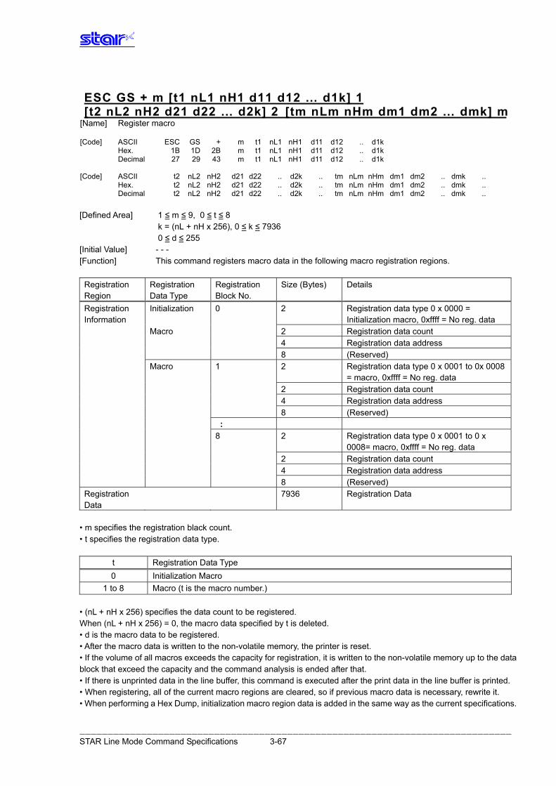
ESC GS + m [t1 nL1 nH1 d11 d12 … d1k] 1 [t2 nL2 nH2 d21 d22 … d2k] 2 [tm nLm nHm dm1 dm2 … dmk] m
[Name] Register macro [Code] ASCII ESC GS + m t1 nL1 nH1 d11 d12 .. d1k Hex. 1B 1D 2B m t1 nL1 nH1 d11 d12 .. d1k Decimal 27 29 43 m t1 nL1 nH1 d11 d12 .. d1k [Code] ASCII t2 nL2 nH2 d21 d22 .. d2k .. tm nLm nHm dm1 dm2 .. dmk .. Hex. t2 nL2 nH2 d21 d22 .. d2k .. tm nLm nHm dm1 dm2 .. dmk .. Decimal t2 nL2 nH2 d21 d22 .. d2k .. tm nLm nHm dm1 dm2 .. dmk .. [Defined Area] 1 ≤ m ≤ 9, 0 ≤ t ≤ 8 k = (nL + nH x 256), 0 ≤ k ≤ 7936 0 ≤ d ≤ 255 [Initial Value] - - - [Function] This command registers macro data in the following macro registration regions.
Registration Region
Registration Data Type
Registration Block No.
Size (Bytes) Details
Registration Information
Initialization 0 2 Registration data type 0 x 0000 = Initialization macro, 0xffff = No reg. data
Macro 2 Registration data count 4 Registration data address 8 (Reserved) Macro 1 2 Registration data type 0 x 0001 to 0x 0008
= macro, 0xffff = No reg. data 2 Registration data count 4 Registration data address 8 (Reserved)
: 8 2 Registration data type 0 x 0001 to 0 x
0008= macro, 0xffff = No reg. data 2 Registration data count 4 Registration data address 8 (Reserved) Registration Data
7936 Registration Data
• m specifies the registration black count. • t specifies the registration data type.
t Registration Data Type 0 Initialization Macro
1 to 8 Macro (t is the macro number.) • (nL + nH x 256) specifies the data count to be registered. When (nL + nH x 256) = 0, the macro data specified by t is deleted. • d is the macro data to be registered. • After the macro data is written to the non-volatile memory, the printer is reset. • If the volume of all macros exceeds the capacity for registration, it is written to the non-volatile memory up to the data block that exceed the capacity and the command analysis is ended after that. • If there is unprinted data in the line buffer, this command is executed after the print data in the line buffer is printed. • When registering, all of the current macro regions are cleared, so if previous macro data is necessary, rewrite it. • When performing a Hex Dump, initialization macro region data is added in the same way as the current specifications.
――――――――――――――――――――――――――――――――――――――――――――――――――――――――――――――――――――――――――――― STAR Line Mode Command Specifications 3-67
3.4. Raster Graphics Command Details Raster graphics are command types and incidental specifications that enable high speed and high quality printing of graphics. The following shows the characteristics and specifications for raster graphics.
• Defines the raster mode command as the STAR line mode extension set. Basically no restrictions set in use of conventional STAR line mode. STAR Page Mode cannot be used. • Handles high speed data transmission When using IEEE 1284, data transmission rate of 80 to 100 KB /sec ensured. • Handles IEEE 1284, USB and Ethernet I/F (RS-232C not applicable) • Handles both fixed length/variable length mode • Print speed selectable • Post printing cut operation selectable • All settings possible by Raster commands. Most settings are possible without DIPSW/memory switch settings. • Supports printer driver handling raster mode
The following shows the raster command details. Note that if not specifically noted, the following commands are effective only in raster mode and the commands are ignored (4 bytes ignored) when other than the raster mode. The raster image buffer in the command details described below indicate the raster dedicated image buffer, the length thereof (vertical direction dot count) differing between models.
――――――――――――――――――――――――――――――――――――――――――――――――――――――――――――――――――――――――――――― STAR Line Mode Command Specifications 3-68
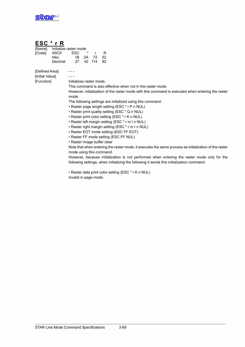
ESC * r R [Name] Initialize raster mode [Code] ASCII ESC * r R Hex. 1B 2A 72 52 Decimal 27 42 114 82 [Defined Area] - - - [Initial Value] - - - [Function] Initializes raster mode. This command is also effective when not in the raster mode. However, initialization of the raster mode with this command is executed when entering the raster
mode. The following settings are initialized using this command. • Raster page length setting (ESC * r P n NUL) • Raster print quality setting (ESC * Q n NUL) • Raster print color setting (ESC * r K n NUL) • Raster left margin setting (ESC * r m l n NUL) • Raster right margin setting (ESC * r m r n NUL) • Raster EOT mode setting (ESC FF EOT) • Raster FF mode setting (ESC FF NUL) • Raster image buffer clear Note that when entering the raster mode, it executes the same process as initialization of the raster
mode using this command. However, because initialization is not performed when entering the raster mode only for the
following settings, when initializing the following it sends this initialization command. • Raster data print color setting (ESC * r K n NUL) Invalid in page mode.
――――――――――――――――――――――――――――――――――――――――――――――――――――――――――――――――――――――――――――― STAR Line Mode Command Specifications 3-69
ESC * r A [Name] Enter raster mode [Code] ASCII ESC * r A Hex. 1B 2A 72 41 Decimal 27 42 114 65 [Defined Area] - - - [Initial Value] - - - [Function] Enters raster mode. This command is ignored when in the raster mode. The following shows the details regard processing of this command. (1) Reception of this command. (2) When using parallel I/F, IEEE 1284 reverse mode is prohibited. (3) All data remaining in the reception buffer and image buffer is printed equivalent to the FF
command. (4) Initialize raster mode (5) Enter raster mode When in the raster mode, the raster mode is initialized. The following shows the contents of the initialization. • Raster page length setting (ESC * r P n NUL) • Raster print quality setting (ESC * Q n NUL) • Raster left margin setting (ESC * r m l n NUL) • Raster right margin setting (ESC * r m r n NUL) • Raster EOT mode setting (ESC FF EOT) • Raster FF mode setting (ESC FF NUT) • Raster image buffer clear (*) Only raster data print color setting is not initialized when entering the raster mode. Invalid in page mode.
――――――――――――――――――――――――――――――――――――――――――――――――――――――――――――――――――――――――――――― STAR Line Mode Command Specifications 3-70
ESC * r B [Name] Quit raster mode [Code] ASCII ESC * r B Hex. 1B 2A 72 42 Decimal 27 42 114 66 [Defined Area] - - - [Initial Value] - - - [Function] Quits raster mode. When quitting the raster mode, if there is raster data remaining in the image buffer of the raster
mode, it quits the raster mode after executing the raster EOT mode. Note that with this command, IEEE 1284 reverse mode is allowed in parallel I/F and it sets the top
of page with the line mode. Invalid in page mode.
ESC * r C [Name] Clear raster data [Code] ASCII ESC * r C Hex. 1B 2A 72 43 Decimal 27 42 114 67 [Defined Area] - - - [Initial Value] - - - [Function] Clears image buffer data in the raster mode. Invalid in page mode.
――――――――――――――――――――――――――――――――――――――――――――――――――――――――――――――――――――――――――――― STAR Line Mode Command Specifications 3-71
ESC * r D n NUL [Name] Drawer drive [Code] ASCII ESC * r D n NUL Hex. 1B 2A 72 44 n 00 Decimal 27 42 114 68 n 0 [Defined Area] 0≤n≤3 [Initial Value] n = 0 [Function] Drives the drawer in the raster mode. Drawer drive conditions conform to setting command (<ESC> <BEL> n1 n2) of the line mode. n is a decimal description (max. 255 digits) using ASCII characters.
n Drive circuits 0 None 1 External device drive 1 drive 2 External device drive 2 drive 3 External device drive 1 drive and external device drive 2 drive
Invalid in page mode.
――――――――――――――――――――――――――――――――――――――――――――――――――――――――――――――――――――――――――――― STAR Line Mode Command Specifications 3-72
ESC * r E n NUL [Name] Set raster EOT mode [Code] ASCII ESC * r E n NUL Hex. 1B 2A 72 45 n 00 Decimal 27 42 114 69 n 0 [Defined Area] n = 0, 1, 2, 3, 8, 9, 12, 13, 36, 37 [Initial Value] Models handling full cut: n = 9 Models connected with a presenter: n = 37 [Function] Sets the raster EOT mode. The EOT mode operates to execute using the raster document quit command (ESC FF EOT). n is a decimal description (max. 255 digits) using ASCII characters. Invalid in page mode. Specification A <EOT mode setting format>
n FormFeed Cut Feed Cutter Presenter 0 Set To Default Set To Default Set To Default Set To Default 1 ○ -- -- -- 2 ○ ○ -- -- 3 ○ TearBar -- -- 8 ○ -- Full Cut -- 9 ○ ○ Full Cut --
12 ○ -- Partial Cut -- 13 ○ ○ Partial Cut -- 36 ○ -- Full Cut Eject 37 ○ ○ Full Cut Eject
Specification B <EOT mode setting format>
n FormFeed Cut Feed Cutter Presenter 0 Set To Default Set To Default Set To Default Set To Default 1 ○ (*1) -- -- -- 2 ○ (*1) ○ -- -- 3 ○ (*1) TearBar -- -- 8 ○ (*1) -- Full Cut -- 9 ○ (*1) ○ Full Cut --
12 ○ (*1) -- Partial Cut -- 13 ○ (*1) ○ Partial Cut -- 36 ○ (*1) -- Full Cut Eject 37 ○ (*1) ○ Full Cut Eject
*1) Form Feed When the printer is a model handling BM and is set for BM to be effective, the set raster mode page length is ignored and BM detecting is performed.
――――――――――――――――――――――――――――――――――――――――――――――――――――――――――――――――――――――――――――― STAR Line Mode Command Specifications 3-73

ESC * r F n NUL [Name] Set raster FF mode [Code] ASCII ESC * r F n NUL Hex. 1B 2A 72 46 n 00 Decimal 27 42 114 70 n 0 [Defined Area] n = 0, 1, 2, 3, 8, 9, 12, 13, 36, 37 [Initial Value] Models handling full cut: n = 9 Models connected with a presenter: n = 37 [Function] Sets raster FF mode. The FF mode operates to execute using the raster document quit command (ESC FF NUL). n is a decimal description (max. 255 digits) using ASCII characters. Invalid in page mode. Specification A <FF mode setting format>
n FormFeed Cut Feed Cutter Presenter 0 Set To Default Set To Default Set To Default Set To Default 1 ○ -- -- -- 2 ○ ○ -- -- 3 ○ TearBar -- -- 8 ○ -- Full Cut -- 9 ○ ○ Full Cut --
12 ○ -- Partial Cut -- 13 ○ ○ Partial Cut -- 36 ○ -- Full Cut Eject 37 ○ ○ Full Cut Eject
Specification B <FF mode setting format>
n FormFeed Cut Feed Cutter Presenter 0 Set To Default Set To Default Set To Default Set To Default 1 ○ (*1) -- -- -- 2 ○ (*1) ○ -- -- 3 ○ (*1) TearBar -- -- 8 ○ (*1) -- Full Cut -- 9 ○ (*1) ○ Full Cut --
12 ○ (*1) -- Partial Cut -- 13 ○ (*1) ○ Partial Cut -- 36 ○ (*1) -- Full Cut Eject 37 ○ (*1) ○ Full Cut Eject
*1) Form Feed When the printer is a model handling BM and is set for BM to be effective, the set raster mode page length is ignored and BM detecting is performed.
――――――――――――――――――――――――――――――――――――――――――――――――――――――――――――――――――――――――――――― STAR Line Mode Command Specifications 3-74
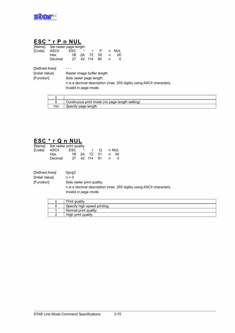
ESC * r P n NUL [Name] Set raster page length [Code] ASCII ESC * r P n NUL Hex. 1B 2A 72 50 n 00 Decimal 27 42 114 80 n 0 [Defined Area] - - - [Initial Value] Raster image buffer length [Function] Sets raster page length. n is a decimal description (max. 255 digits) using ASCII characters. Invalid in page mode.
n 0 Continuous print mode (no page length setting)
1≤n Specify page length
ESC * r Q n NUL [Name] Set raster print quality [Code] ASCII ESC * r Q n NUL Hex. 1B 2A 72 51 n 00 Decimal 27 42 114 81 n 0 [Defined Area] 0≤n≤2 [Initial Value] n = 0 [Function] Sets raster print quality. n is a decimal description (max. 255 digits) using ASCII characters. Invalid in page mode.
n Print quality 0 Specify high speed printing 1 Normal print quality 2 High print quality
――――――――――――――――――――――――――――――――――――――――――――――――――――――――――――――――――――――――――――― STAR Line Mode Command Specifications 3-75
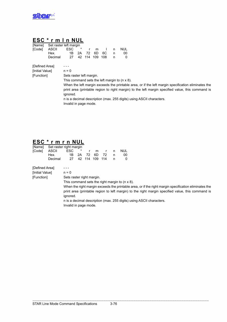
ESC * r m l n NUL [Name] Set raster left margin [Code] ASCII ESC * r m l n NUL Hex. 1B 2A 72 6D 6C n 00 Decimal 27 42 114 109 108 n 0 [Defined Area] - - - [Initial Value] n = 0 [Function] Sets raster left margin. This command sets the left margin to (n x 8). When the left margin exceeds the printable area, or if the left margin specification eliminates the
print area (printable region to right margin) to the left margin specified value, this command is ignored.
n is a decimal description (max. 255 digits) using ASCII characters. Invalid in page mode.
ESC * r m r n NUL [Name] Set raster right margin [Code] ASCII ESC * r m r n NUL Hex. 1B 2A 72 6D 72 n 00 Decimal 27 42 114 109 114 n 0 [Defined Area] - - - [Initial Value] n = 0 [Function] Sets raster right margin. This command sets the right margin to (n x 8). When the right margin exceeds the printable area, or if the right margin specification eliminates the
print area (printable region to left margin) to the right margin specified value, this command is ignored.
n is a decimal description (max. 255 digits) using ASCII characters. Invalid in page mode.
――――――――――――――――――――――――――――――――――――――――――――――――――――――――――――――――――――――――――――― STAR Line Mode Command Specifications 3-76
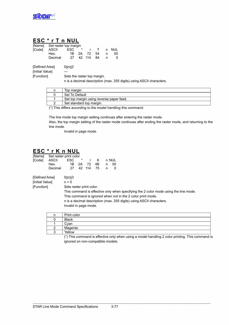
ESC * r T n NUL [Name] Set raster top margin [Code] ASCII ESC * r T n NUL Hex. 1B 2A 72 54 n 00 Decimal 27 42 114 84 n 0 [Defined Area] 0≤n≤2 [Initial Value] --- [Function] Sets the raster top margin. n is a decimal description (max. 255 digits) using ASCII characters.
n Top margin 0 Set To Default 1 Set top margin using reverse paper feed. 2 Set standard top margin.
(*) This differs according to the model handling this command. The line mode top margin setting continues after entering the raster mode. Also, the top margin setting of the raster mode continues after ending the raster mode, and returning to the line mode. Invalid in page mode.
ESC * r K n NUL [Name] Set raster print color [Code] ASCII ESC * r K n NUL Hex. 1B 2A 72 4B n 00 Decimal 27 42 114 75 n 0 [Defined Area] 0≤n≤3 [Initial Value] n = 0 [Function] Sets raster print color. This command is effective only when specifying the 2 color mode using the line mode. This command is ignored when not in the 2 color print mode. n is a decimal description (max. 255 digits) using ASCII characters. Invalid in page mode.
n Print color 0 Black 1 Cyan 2 Magenta 3 Yellow
(*) This command is effective only when using a model handling 2 color printing. This command is ignored on non-compatible models.
――――――――――――――――――――――――――――――――――――――――――――――――――――――――――――――――――――――――――――― STAR Line Mode Command Specifications 3-77
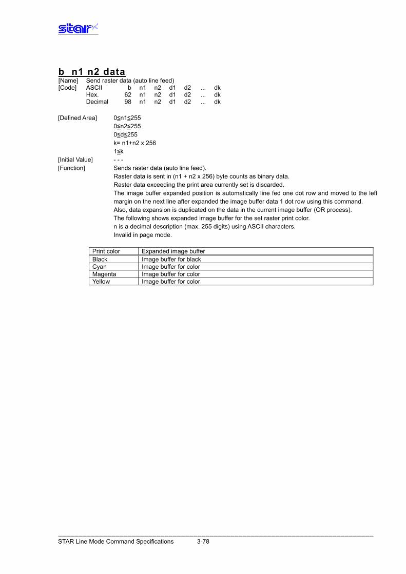
b n1 n2 data [Name] Send raster data (auto line feed) [Code] ASCII b n1 n2 d1 d2 ... dk Hex. 62 n1 n2 d1 d2 ... dk Decimal 98 n1 n2 d1 d2 ... dk [Defined Area] 0≤n1≤255 0≤n2≤255 0≤d≤255 k= n1+n2 x 256 1≤k [Initial Value] - - - [Function] Sends raster data (auto line feed). Raster data is sent in (n1 + n2 x 256) byte counts as binary data. Raster data exceeding the print area currently set is discarded. The image buffer expanded position is automatically line fed one dot row and moved to the left
margin on the next line after expanded the image buffer data 1 dot row using this command. Also, data expansion is duplicated on the data in the current image buffer (OR process). The following shows expanded image buffer for the set raster print color. n is a decimal description (max. 255 digits) using ASCII characters. Invalid in page mode.
Print color Expanded image buffer Black Image buffer for black Cyan Image buffer for color Magenta Image buffer for color Yellow Image buffer for color
――――――――――――――――――――――――――――――――――――――――――――――――――――――――――――――――――――――――――――― STAR Line Mode Command Specifications 3-78
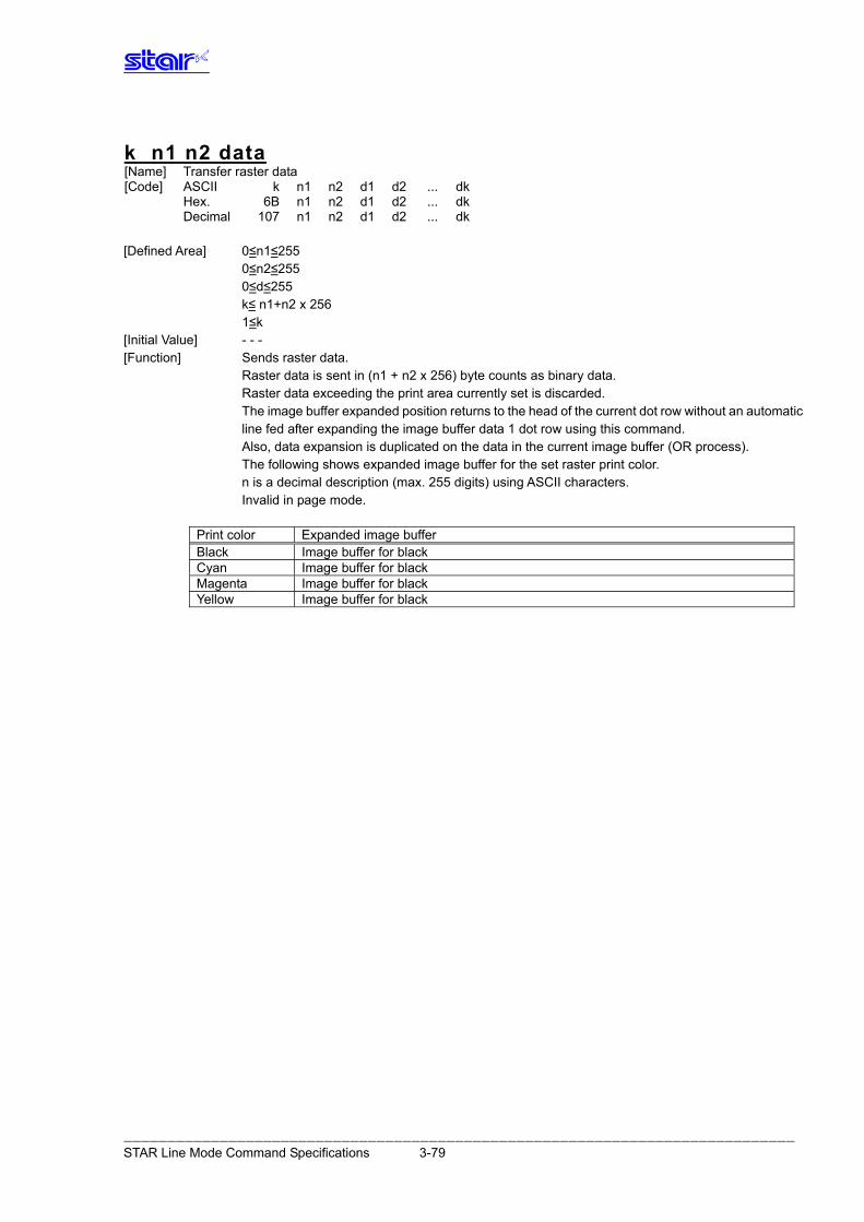
k n1 n2 data [Name] Transfer raster data [Code] ASCII k n1 n2 d1 d2 ... dk Hex. 6B n1 n2 d1 d2 ... dk Decimal 107 n1 n2 d1 d2 ... dk [Defined Area] 0≤n1≤255 0≤n2≤255 0≤d≤255 k≤ n1+n2 x 256 1≤k [Initial Value] - - - [Function] Sends raster data. Raster data is sent in (n1 + n2 x 256) byte counts as binary data. Raster data exceeding the print area currently set is discarded. The image buffer expanded position returns to the head of the current dot row without an automatic
line fed after expanding the image buffer data 1 dot row using this command. Also, data expansion is duplicated on the data in the current image buffer (OR process). The following shows expanded image buffer for the set raster print color. n is a decimal description (max. 255 digits) using ASCII characters. Invalid in page mode.
Print color Expanded image buffer Black Image buffer for black Cyan Image buffer for black Magenta Image buffer for black Yellow Image buffer for black
――――――――――――――――――――――――――――――――――――――――――――――――――――――――――――――――――――――――――――― STAR Line Mode Command Specifications 3-79
ESC * r Y n NUL [Name] Move vertical direction position (Line feed for specified dots) [Code] ASCII ESC * r Y n NUL Hex. 1B 2A 72 59 n 00 Decimal 27 42 114 89 n 0 [Defined Area] - - - [Initial Value] - - - [Function] Moves vertical direction position. Moves position n dots with this command. When the current page length setting is in continuous print mode, and the n dots exceed the
remaining dot count of the raster image buffer length, this moves up to the remaining dot count and ignores the overflow.
If the page length is set, it moves to the current page length and ignores the overflow. Note that when there is overflow, this expands the next raster data after printing the raster image
buffer data with the next raster data transfer and move vertical direction position command. n is a decimal description (max. 255 digits) using ASCII characters. Invalid in page mode.
――――――――――――――――――――――――――――――――――――――――――――――――――――――――――――――――――――――――――――― STAR Line Mode Command Specifications 3-80
ESC FF NUL [Name] Execute FF mode [Code] ASCII ESC FF NUL Hex. 1B 0C 00 Decimal 27 12 0 [Defined Area] - - - [Initial Value] - - - [Function] Executes FF mode. Executes operation specified by the FF mode setting command (ESC * r F n NUL). Invalid in page mode.
ESC FF EOT [Name] Execute EOT mode [Code] ASCII ESC FF EOT Hex. 1B 0C 04 Decimal 27 12 4 [Defined Area] - - - [Initial Value] - - - [Function] Executes EOT mode. Executes operation specified by the EOT mode setting command (ESC * r E n NUL). Invalid in page mode.
ESC * r N n NUL [Name] Discard data for specified byte count [Code] ASCII ESC * r N n NUL Hex. 1B 2A 72 4E n 0 Decimal 27 42 114 78 n 0 [Defined Area] 1≤n≤255 [Initial Value] - - - [Function] Discards data for the specified byte count. Discards data received after a byte count specified by n. n is expressed in decimal (maximum 4 digits) using ASCII characters. This command is effective only in raster mode. Invalid in page mode.
――――――――――――――――――――――――――――――――――――――――――――――――――――――――――――――――――――――――――――― STAR Line Mode Command Specifications 3-81
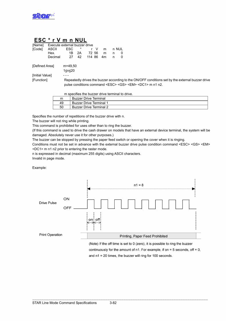
ESC * r V m n NUL [Name] Execute external buzzer drive [Code] ASCII ESC * r V m n NUL Hex. 1B 2A 72 56 m n 0 Decimal 27 42 114 86 4m n 0 [Defined Area] m=49,50 1≤n≤20 [Initial Value] - - - [Function] Repeatedly drives the buzzer according to the ON/OFF conditions set by the external buzzer drive pulse conditions command <ESC> <GS> <EM> <DC1> m n1 n2. m specifies the buzzer drive terminal to drive.
m Buzzer Drive Terminal 49 Buzzer Drive Terminal 1 50 Buzzer Drive Terminal 2
Specifies the number of repetitions of the buzzer drive with n. The buzzer will not ring while printing. This command is prohibited for uses other than to ring the buzzer. (If this command is used to drive the cash drawer on models that have an external device terminal, the system will be damaged. Absolutely never use it for other purposes.) The buzzer can be stopped by pressing the paper feed switch or opening the cover when it is ringing. Conditions must not be set in advance with the external buzzer drive pulse condition command <ESC> <GS> <EM> <DC1> m n1 n2 prior to entering the raster mode. n is expressed in decimal (maximum 255 digits) using ASCII characters. Invalid in page mode. Example:
――――――――――――――――――――――――――――――――――――――――――――――――――――――――――――――――――――――――――――― STAR Line Mode Command Specifications 3-82
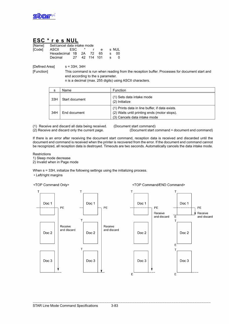
ESC * r e s NUL [Name] Set/cancel data intake mode [Code] ASCII ESC * r e s NUL Hexadecimal 1B 2A 72 65 s 00 Decimal 27 42 114 101 s 0 [Defined Area] s = 33H, 34H [Function] This command is run when reading from the reception buffer. Processes for document start and end according to the s parameter.
n is a decimal (max. 255 digits) using ASCII characters.
s Name Function
(1) Sets data intake mode 33H Start document
(2) Initialize
(1) Prints data in line buffer, if data exists. 34H End document (2) Waits until printing ends (motor stops).
(3) Cancels data intake mode (1) Receive and discard all data being received. (Document start command) (2) Receive and discard only the current page. (Document start command + document end command) If there is an error after receiving the document start command, reception data is received and discarded until the document end command is received when the printer is recovered from the error. If the document end command cannot be recognized, all reception data is destroyed. Timeouts are two seconds. Automatically cancels the data intake mode. Restrictions 1) Sleep mode decrease 2) Invalid when in Page mode When s = 33H, initialize the following settings using the initializing process. • Left/right margins
――――――――――――――――――――――――――――――――――――――――――――――――――――――――――――――――――――――――――――― STAR Line Mode Command Specifications 3-83
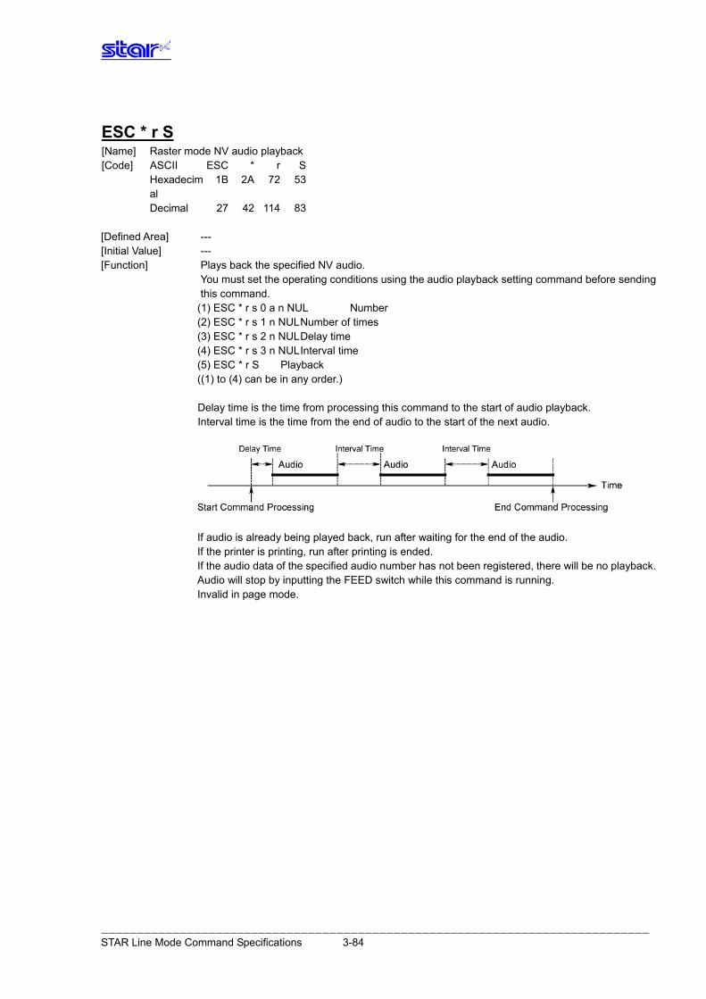
ESC * r S [Name] Raster mode NV audio playback [Code] ASCII ESC * r S Hexadecim
al 1B 2A 72 53
Decimal 27 42 114 83 [Defined Area] --- [Initial Value] --- [Function] Plays back the specified NV audio.
You must set the operating conditions using the audio playback setting command before sending this command.
(1) ESC * r s 0 a n NUL Number (2) ESC * r s 1 n NUL Number of times (3) ESC * r s 2 n NUL Delay time (4) ESC * r s 3 n NUL Interval time (5) ESC * r S Playback ((1) to (4) can be in any order.) Delay time is the time from processing this command to the start of audio playback. Interval time is the time from the end of audio to the start of the next audio.
If audio is already being played back, run after waiting for the end of the audio. If the printer is printing, run after printing is ended. If the audio data of the specified audio number has not been registered, there will be no playback. Audio will stop by inputting the FEED switch while this command is running. Invalid in page mode.
――――――――――――――――――――――――――――――――――――――――――――――――――――――――――――――――――――――――――――― STAR Line Mode Command Specifications 3-84
ESC * r s 0 a n NUL [Name] Set raster mode NV audio playback number [Code] ASCII ESC * r s 0 a n NUL Hexadecim
al 1B 2A 72 73 30 a n 00
Decimal 27 42 114 115 48 a n 0 [Defined Area] a = 48, 49
‘1’ ≤ n ≤ ’255’ [Initial Value] No audio playback number setting. [Function] Set the audio playback number to play in the raster mode audio playback command (ESC * r S).
a specifies the area where the audio data to playback is stored. a Audio data storage area
49 User area n is a decimal description (max. 5 digits) using ASCII characters. No setting when the parameter is not defined. Invalid in Page Mode.
――――――――――――――――――――――――――――――――――――――――――――――――――――――――――――――――――――――――――――― STAR Line Mode Command Specifications 3-85
ESC * r s 1 n NUL [Name] Set raster mode NV audio playback count [Code] ASCII ESC * r s 1 n NUL Hexadecim
al 1B 2A 72 73 31 n 00
Decimal 27 42 114 115 49 n 0 [Defined Area] ‘1’ ≤ n ≤ ’65535’ [Initial Value] No audio playback count setting. [Function] Set the audio playback count to n times in the raster mode audio playback command (ESC * r S).
n is a decimal description (max. 5 digits) using ASCII characters. No setting when the parameter is not defined. Invalid in page mode.
ESC * r s 2 n NUL [Name] Set raster mode NV audio playback delay time [Code] ASCII * r s 2 n NUL ESC Hexadecimal 1B 2A 72 73 32 n 00 Decimal 27 42 114 115 50 n 0 [Defined Area] ‘0’ ≤ n ≤ ’65535’ [Initial Value] n = ‘0’ [Function] Set the audio playback delay time to n second in the raster mode audio playback command
(ESC * r S). Delay time is the time from starting processing of the raster mode audio playback command
(ESC * r S) to the start of audio playback. n is a decimal description (max. 5 digits) using ASCII characters. No setting when the parameter is not defined. Invalid in page mode.
ESC * r s 3 n NUL [Name] Set raster mode NV audio playback interval time [Code] ASCII ESC * r s 3 n NUL Hexadecimal 1B 2A 72 73 33 n 00 Decimal 27 42 114 115 51 n 0 [Defined Area] ‘0’ ≤ n ≤ ’65535’ [Initial Value] n = ‘0’ [Function] Set the audio playback interval time to n second in the raster mode audio playback command
(ESC * r S). Interval time is the time from the end of audio to the start of the next audio. n is a decimal description (max. 5 digits) using ASCII characters. No setting when the parameter is not defined. Invalid in page mode.
――――――――――――――――――――――――――――――――――――――――――――――――――――――――――――――――――――――――――――― STAR Line Mode Command Specifications 3-86
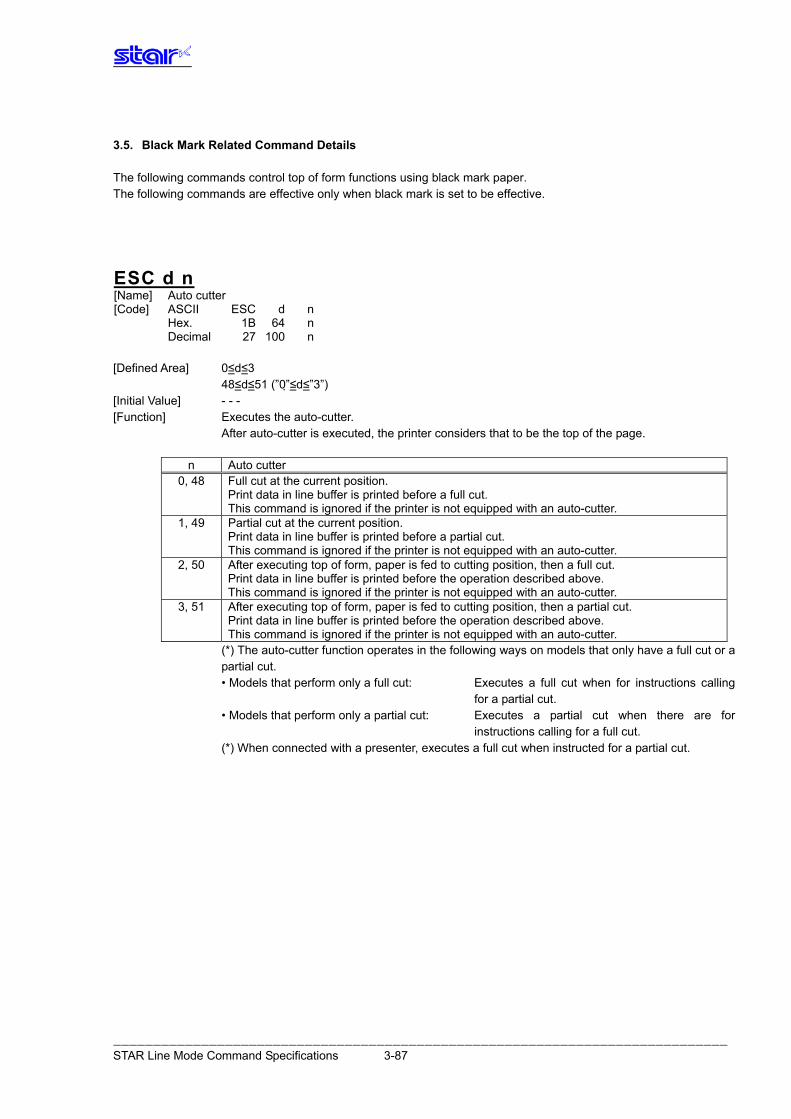
3.5. Black Mark Related Command Details The following commands control top of form functions using black mark paper. The following commands are effective only when black mark is set to be effective.
ESC d n [Name] Auto cutter [Code] ASCII ESC d n Hex. 1B 64 n Decimal 27 100 n [Defined Area] 0≤d≤3 48≤d≤51 (”0”≤d≤”3”) [Initial Value] - - - [Function] Executes the auto-cutter. After auto-cutter is executed, the printer considers that to be the top of the page.
n Auto cutter 0, 48 Full cut at the current position.
Print data in line buffer is printed before a full cut. This command is ignored if the printer is not equipped with an auto-cutter.
1, 49 Partial cut at the current position. Print data in line buffer is printed before a partial cut. This command is ignored if the printer is not equipped with an auto-cutter.
2, 50 After executing top of form, paper is fed to cutting position, then a full cut. Print data in line buffer is printed before the operation described above. This command is ignored if the printer is not equipped with an auto-cutter.
3, 51 After executing top of form, paper is fed to cutting position, then a partial cut. Print data in line buffer is printed before the operation described above. This command is ignored if the printer is not equipped with an auto-cutter.
(*) The auto-cutter function operates in the following ways on models that only have a full cut or a partial cut.
• Models that perform only a full cut: Executes a full cut when for instructions calling for a partial cut.
• Models that perform only a partial cut: Executes a partial cut when there are for instructions calling for a full cut.
(*) When connected with a presenter, executes a full cut when instructed for a partial cut.
――――――――――――――――――――――――――――――――――――――――――――――――――――――――――――――――――――――――――――― STAR Line Mode Command Specifications 3-87
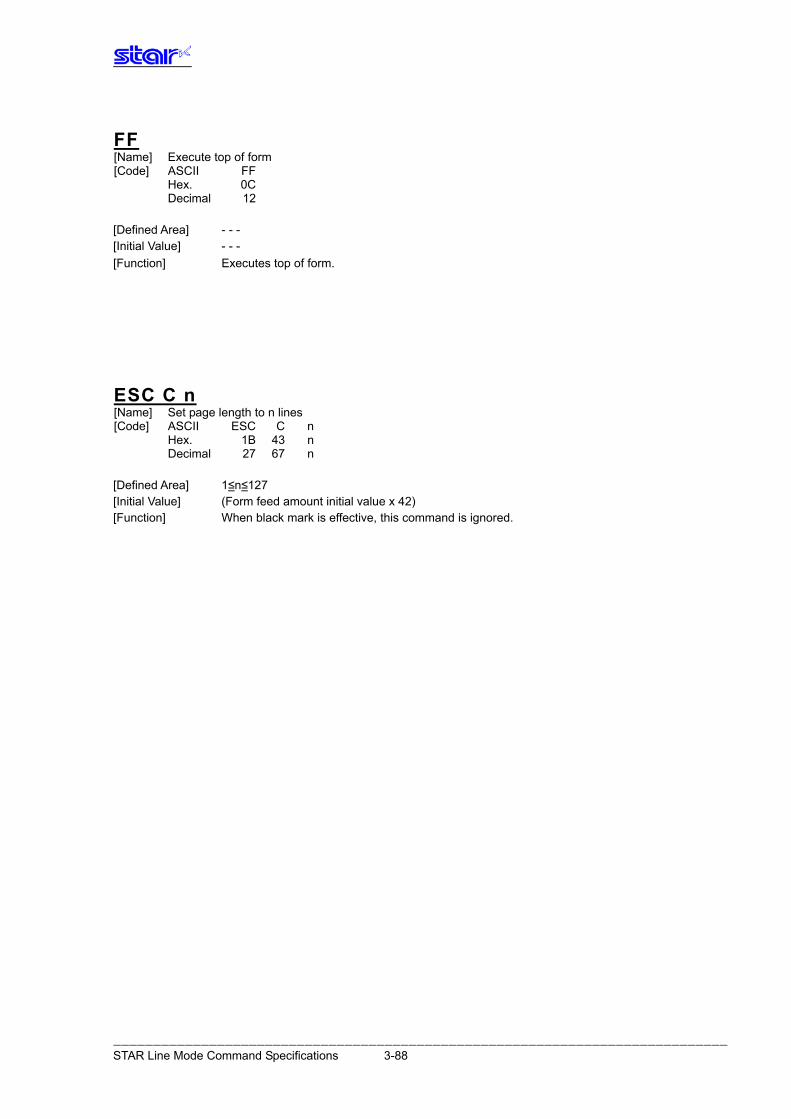
FF [Name] Execute top of form [Code] ASCII FF Hex. 0C Decimal 12 [Defined Area] - - - [Initial Value] - - - [Function] Executes top of form.
ESC C n [Name] Set page length to n lines [Code] ASCII ESC C n Hex. 1B 43 n Decimal 27 67 n [Defined Area] 1≤n≤127 [Initial Value] (Form feed amount initial value x 42) [Function] When black mark is effective, this command is ignored.
――――――――――――――――――――――――――――――――――――――――――――――――――――――――――――――――――――――――――――― STAR Line Mode Command Specifications 3-88
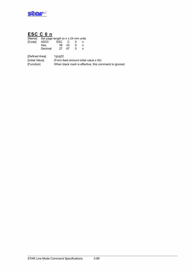
ESC C 0 n [Name] Set page length to n x 24 mm units [Code] ASCII ESC C 0 n Hex. 1B 43 0 n Decimal 27 67 0 n [Defined Area] 1≤n≤22 [Initial Value] (Form feed amount initial value x 42) [Function] When black mark is effective, this command is ignored.
――――――――――――――――――――――――――――――――――――――――――――――――――――――――――――――――――――――――――――― STAR Line Mode Command Specifications 3-89
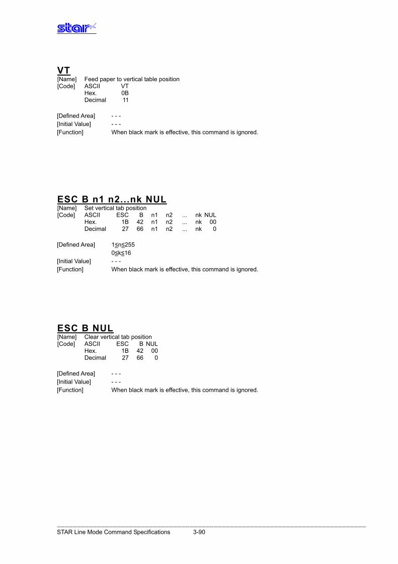
VT [Name] Feed paper to vertical table position [Code] ASCII VT Hex. 0B Decimal 11 [Defined Area] - - - [Initial Value] - - - [Function] When black mark is effective, this command is ignored.
ESC B n1 n2...nk NUL [Name] Set vertical tab position [Code] ASCII ESC B n1 n2 ... nk NUL Hex. 1B 42 n1 n2 ... nk 00 Decimal 27 66 n1 n2 ... nk 0 [Defined Area] 1≤n≤255 0≤k≤16 [Initial Value] - - - [Function] When black mark is effective, this command is ignored.
ESC B NUL [Name] Clear vertical tab position [Code] ASCII ESC B NUL Hex. 1B 42 00 Decimal 27 66 0 [Defined Area] - - - [Initial Value] - - - [Function] When black mark is effective, this command is ignored.
――――――――――――――――――――――――――――――――――――――――――――――――――――――――――――――――――――――――――――― STAR Line Mode Command Specifications 3-90
3.6. USB Related Command Details The following commands control USB I/F functions. There are no corresponding commands.
――――――――――――――――――――――――――――――――――――――――――――――――――――――――――――――――――――――――――――― STAR Line Mode Command Specifications 3-91
3.7. 2 Color Printing Command Details The following commands control 2 color printing functions. The following commands are effective only when using a model handling 2 color printing.
ESC RS c n [Name] Set print color in 2 color print mode [Code] ASCII ESC RS c n Hex. 1B 1E 63 n Decimal 27 30 99 n [Defined Area] 0≤n≤1 48≤n≤49 (”0”≤n≤”1”) [Initial Value] n = 0, 48 (When in 2 color print mode) [Function] Specifies print color in 2 color print mode. This command is ignored when not in the 2 color print mode. Specifies black for the print color when in 2 color print mode. This command is cleared only when the printer is reset. The specification of this command is not cleared by ESC @ CAN. However, print color is initialized to black by the ESC @ and CAN only when in the compatible 2
color print mode.
n Specifies 2 color print mode color 0, 48 Black 1, 49 Red
――――――――――――――――――――――――――――――――――――――――――――――――――――――――――――――――――――――――――――― STAR Line Mode Command Specifications 3-92
ESC RS C n [Name] Select/cancel 2 color print mode [Code] ASCII ESC RS C n Hex. 1B 1E 43 n Decimal 27 30 67 n [Defined Area] Specification A 0≤n≤2 48≤n≤50 (”0”≤n≤”2”) Specification B 0≤n≤1 48≤n≤49 (”0”≤n≤”1”) Specification C 0≤n≤2 48≤n≤50 (”0”≤n≤”2”) n = 16, n = 32 [Initial Value] n = 0, 48 [Function] Specification A
n Select/cancel 2 color print mode 0, 48 Cancel 2-color printing mode
When in two-color print mode, this command cancels 2-color printing mode. This command is ignored when the 2-color print mode is already cancelled. The specification of this command is not cleared by ESC @, CAN. The following processes are executed by canceling the 2-color print mode using this command.
• Prints data in line buffer in 2-color print mode, if unprinted data exists in the line buffer. • Waits to stop printing when printing in 2-color print mode.
• Recovers logo print setting to single color mode setting.
1, 49 Select 2-color printing mode This command selects 2-color print mode, when in single color print mode. This command is ignored already in the 2-color print mode. The specification of this command is not cleared by ESC @, CAN. The following processes are executed by selecting the 2-color print mode using this command.
• Prints data in line buffer in the single color print mode, if unprinted data exists in the line buffer.
• Waits to stop printing when printing in single-color print mode. • Initializes print color setting (2-color print mode setting) • Sets logo print setting to 2 color mode setting.
Invalid in page mode.
――――――――――――――――――――――――――――――――――――――――――――――――――――――――――――――――――――――――――――― STAR Line Mode Command Specifications 3-93
Specification B
n Select/cancel 2 color print mode 0, 48 Cancel 2-color printing mode
When in two-color print mode, this command cancels 2-color printing mode. This command is ignored when the 2-color print mode is already cancelled. The specification of this command is not cleared by ESC @, CAN. The following processes are executed by canceling the 2-color print mode using this command.
• Prints data in line buffer in 2-color print mode, if unprinted data exists in the line buffer. • Waits to stop printing when printing in 2-color print mode.
• Recovers logo print setting to single color mode setting. 1, 49 Select 2-color printing mode
This command selects 2-color print mode, when in single color print mode. This command is ignored already in the 2-color print mode. The specification of this command is not cleared by ESC @, CAN. The following processes are executed by selecting the 2-color print mode using this command.
• Prints data in line buffer in the single color print mode, if unprinted data exists in the line buffer.
• Waits to stop printing when printing in single-color print mode. • Initializes print color setting (2-color print mode setting) • Sets logo print setting to 2 color mode setting.
Specification C
n Specify print mode 0, 48 Single color print mode 1, 49 2-color print mode 2, 50 Dot compatible 2-color mode 16 Low power consumption mode 32 Double resolution mode
• If set to the low power consumption mode using the DIP switches, this command is ignored. • This command is not cleared by ESC @, CAN. • When there is unprinted data in the line buffer, print the line buffer data. • This command is processed after ending the current print job.
――――――――――――――――――――――――――――――――――――――――――――――――――――――――――――――――――――――――――――― STAR Line Mode Command Specifications 3-94
ESC 4 [Name] Select white/black inverted printing [Code] ASCII ESC 4 Hex. 1B 34 Decimal 27 52 [Defined Area] - - - [Initial Value] White/black inversion cancelled [Function] Specifies white/black inversion for ANK characters and Kanji characters. IBM block ignores white/black inversion.
ESC 5 [Name] Cancel white/black inversion [Code] ASCII ESC 5 Hex. 1B 35 Decimal 27 53 [Defined Area] - - - [Initial Value] White/black inversion cancelled [Function] Cancels white/black inversion for ANK characters and Kanji characters.
――――――――――――――――――――――――――――――――――――――――――――――――――――――――――――――――――――――――――――― STAR Line Mode Command Specifications 3-95
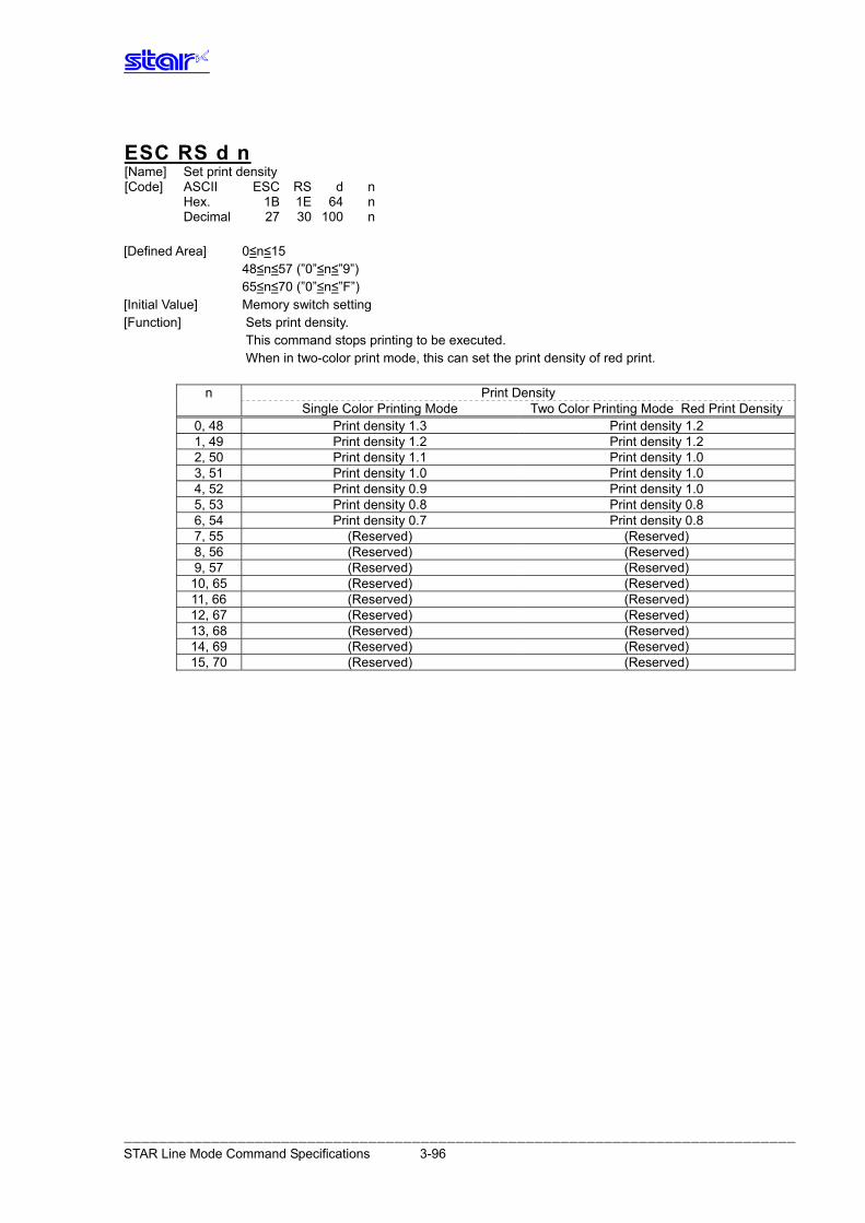
ESC RS d n [Name] Set print density [Code] ASCII ESC RS d n Hex. 1B 1E 64 n Decimal 27 30 100 n [Defined Area] 0≤n≤15 48≤n≤57 (”0”≤n≤”9”) 65≤n≤70 (”0”≤n≤”F”) [Initial Value] Memory switch setting [Function] Sets print density.
This command stops printing to be executed. When in two-color print mode, this can set the print density of red print.
n Print Density Single Color Printing Mode Two Color Printing Mode Red Print Density
0, 48 Print density 1.3 Print density 1.2 1, 49 Print density 1.2 Print density 1.2 2, 50 Print density 1.1 Print density 1.0 3, 51 Print density 1.0 Print density 1.0 4, 52 Print density 0.9 Print density 1.0 5, 53 Print density 0.8 Print density 0.8 6, 54 Print density 0.7 Print density 0.8 7, 55 (Reserved) (Reserved) 8, 56 (Reserved) (Reserved) 9, 57 (Reserved) (Reserved) 10, 65 (Reserved) (Reserved) 11, 66 (Reserved) (Reserved) 12, 67 (Reserved) (Reserved) 13, 68 (Reserved) (Reserved) 14, 69 (Reserved) (Reserved) 15, 70 (Reserved) (Reserved)
――――――――――――――――――――――――――――――――――――――――――――――――――――――――――――――――――――――――――――― STAR Line Mode Command Specifications 3-96
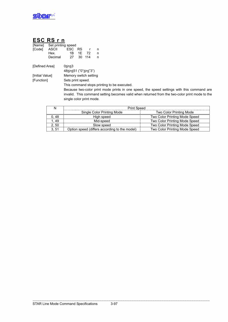
ESC RS r n [Name] Set printing speed [Code] ASCII ESC RS r n Hex. 1B 1E 72 n Decimal 27 30 114 n [Defined Area] 0≤n≤3 48≤n≤51 (”0”≤n≤”3”) [Initial Value] Memory switch setting [Function] Sets print speed. This command stops printing to be executed. Because two-color print mode prints in one speed, the speed settings with this command are
invalid. This command setting becomes valid when returned from the two-color print mode to the single color print mode.
N Print Speed Single Color Printing Mode Two Color Printing Mode
0, 48 High speed Two Color Printing Mode Speed 1, 49 Mid-speed Two Color Printing Mode Speed 2, 50 Slow speed Two Color Printing Mode Speed 3, 51 Option speed (differs according to the model) Two Color Printing Mode Speed
――――――――――――――――――――――――――――――――――――――――――――――――――――――――――――――――――――――――――――― STAR Line Mode Command Specifications 3-97
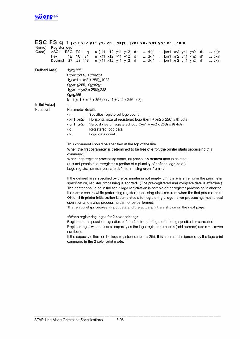
ESC FS q n [x11 x12 y11 y12 d1. . .dk]1. . . [xn1 xn2 yn1 yn2 d1. . .dk]n [Name] Register logo [Code] ASCII ESC FS n [x11 x12 y11 y12 d1 … dk]1 … [xn1 xn2 yn1 yn2 d1 ... dk]nq Hex. 1B 1C 71 n [x11 x12 y11 y12 d1 … dk]1 … [xn1 xn2 yn1 yn2 d1 ... dk]n Decimal 27 28 113 n [x11 x12 y11 y12 d1 … dk]1 … [xn1 xn2 yn1 yn2 d1 ... dk]n [Defined Area] 1≤n≤255 0≤xn1≤255, 0≤xn2≤3 1≤(xn1 + xn2 x 256)≤1023 0≤yn1≤255, 0≤yn2≤1 1≤yn1 + yn2 x 256)≤288 0≤d≤255 k = {(xn1 + xn2 x 256) x (yn1 + yn2 x 256) x 8} [Initial Value] - - - [Function] Parameter details • n: Specifies registered logo count • xn1, xn2: Horizontal size of registered logo {(xn1 + xn2 x 256) x 8} dots • yn1, yn2: Vertical size of registered logo {(yn1 + yn2 x 256) x 8} dots • d: Registered logo data • k: Logo data count This command should be specified at the top of the line. When the first parameter is determined to be free of error, the printer starts processing this
command. When logo register processing starts, all previously defined data is deleted. (It is not possible to reregister a portion of a plurality of defined logo data.) Logo registration numbers are defined in rising order from 1.
If the defined area specified by the parameter is not empty, or if there is an error in the parameter
specification, register processing is aborted. (The pre-registered and complete data is effective.) The printer should be initialized if logo registration is completed or register processing is aborted. If an error occurs while performing register processing (the time from when the first parameter is
OK until th printer initialization is completed after registering a logo), error processing, mechanical operation and status processing cannot be performed.
The relationships between input data and the actual print are shown on the next page. <When registering logos for 2 color printing> Registration is possible regardless of the 2 color printing mode being specified or cancelled. Register logos with the same capacity as the logo register number n (odd number) and n + 1 (even
number). If the capacity differs or the logo register number is 255, this command is ignored by the logo print
command in the 2 color print mode.
――――――――――――――――――――――――――――――――――――――――――――――――――――――――――――――――――――――――――――― STAR Line Mode Command Specifications 3-98
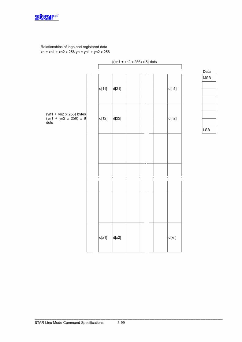
Relationships of logo and registered data xn = xn1 + xn2 x 256 yn = yn1 + yn2 x 256 {(xn1 + xn2 x 256) x 8} dots
Data
MSB
d[11] d[21] d[n1]
(yn1 + yn2 x 256) bytes (yn1 + yn2 x 256) x 8 dots
d[12] d[22] d[n2]
LSB
d[x1] d[x2] d[xn]
――――――――――――――――――――――――――――――――――――――――――――――――――――――――――――――――――――――――――――― STAR Line Mode Command Specifications 3-99
ESC FS p n m [Name] Print logo [Code] ASCII ESC FS p n m Hex. 1B 1C 70 n m Decimal 27 28 112 n m [Defined Area] 1≤n≤255 0≤m≤3 48≤m≤51 (”0”≤m≤”3”) [Initial Value] - - - [Function] Prints the logo of registration number n registered using the logo registration command (ESC FS q)
according to the print mode m.
m Logo print mode 0, 48 Normal mode 1, 49 Double wide mode 2, 50 Double high mode 3, 51 Double high/wide mode
If there is unprinted data in the line buffer, this command is executed after printing that data.
Therefore, it is not possible to print with other data in the same line (characters, bit images, bar codes).
Form feed obeys the vertical print size of the logo. Adornments other than upside-down printing and expansion settings are unaffected. The horizontal printing start position conforms to the left margin position and the horizontal print
area conforms to the left and right margin settings. If the logo horizontal print size exceeds the horizontal print region, the portion exceeding the area
is not printed. <When using the 2 color print mode> When the logo register number n is odd: Register number n is printed in black; register number n + 1 is printed in red and overlapped. The command is ignored when the capacity of the register number n and the capacity of the
register number n + 1 are different. The command is ignored when the register number n = 255 is specified. When the logo register number n is even: Register number n is printed in black; register number n - 1 is printed in red and overlapped. The command is ignored when the capacity of the register number n and the capacity of the
register number n - 1 are different. The command is ignored when the register number n = 255 is specified.
――――――――――――――――――――――――――――――――――――――――――――――――――――――――――――――――――――――――――――― STAR Line Mode Command Specifications 3-100
3.8. Presenter Related Command Details The following commands control the presenter functions. The following commands are effective only on models equipped with a presenter.
ESC SYN 0 n [Name] Execute presenter paper recovery [Code] ASCII ESC SYN 0 n Hex. 1B 16 30 n Decimal 27 22 48 n [Defined Area] n = 0, n = 48 (“0”) [Initial Value] - - - [Function] Executes presenter paper recovery. This command is ignored when a presenter is not connected. Also, this command is executed when paper is supplied by the presenter, exists in the presenter
and the paper has been cut. This command is ignored with under all other conditions. (Ignored when paper is being recovered.)
ESC SYN 1 n [Name] Set presenter paper automatic recovery function and automatic recovery time [Code] ASCII ESC SYN 1 n Hex. 1B 16 31 n Decimal 27 22 49 n [Defined Area] 0≤n≤255 [Initial Value] Memory switch setting [Function] Sets presenter paper automatic recovery function and automatic recovery time. This command is ignored when a presenter is not connected. Settings using this command are effective from the next sheet when the printer processes this
command and paper has already been supplied to the presenter.
N Functions n = 0 Paper automatic recovery function invalid.
1≤n≤255 Paper automatic recovery function valid. Automatic recovery time: n x 0.5 sec (0.5 sec to 127.5 sec)
――――――――――――――――――――――――――――――――――――――――――――――――――――――――――――――――――――――――――――― STAR Line Mode Command Specifications 3-101
ESC SYN 3 n [Name] Acquire presenter paper counter [Code] ASCII ESC SYN 3 n Hex. 1B 16 33 n Decimal 27 22 51 n [Defined Area] n = 0, 1 n = 48, 49 (”0”, “1”) [Initial Value] - - - [Function] Acquires presenter paper counter. This command is ignored when a presenter is not connected. Counter can count to 0xFFFFFFFF sheets. Counter is cleared to zero when the following conditions are met. • At a printer reset • At the <CAN> command • At the <ESC> <SYN> 4 n command The paper counter using this command sends the counter value at the time this command is
processed. The counter is counted up when paper is completely recovered or when pulled out. The counter counts from when the power is turned ON, excluding the following. • When paper is discharged because of an error • When printing using self-print • When paper in the presenter is discharged when the power is turned ON
N Counter n = 0, 48 Acquires paper reel counter n = 1, 49 Acquires paper recovery counter
<Counter transmission format from printer: When using the paper reel counter> Printer transmission: ESC SYN 3 n c1 c2 c3 c4 Reel counter: c4 + (c3 x 256) + (c2 x 256 x 256) + (c1 x 256 x 256 x256)
――――――――――――――――――――――――――――――――――――――――――――――――――――――――――――――――――――――――――――― STAR Line Mode Command Specifications 3-102
ESC SYN 4 n [Name] Initialize presenter paper counter [Code] ASCII ESC SYN 4 n Hex. 1B 16 34 n Decimal 27 22 52 n [Defined Area] n = 0 [Initial Value] - - - [Function] Initializes the presenter paper counter (paper reel counter/paper recovery counter). Initialization of the paper counter using this command is executed when this command is
processed.
――――――――――――――――――――――――――――――――――――――――――――――――――――――――――――――――――――――――――――― STAR Line Mode Command Specifications 3-103
ESC GS SUB DC1 m t1 t2 [Name] Specify snout operation mode
ESC GS SUB DC1 m t1 t2[Code] ASCII 1B 1D 1A 11 m t1 t2 Hexadecimal
Decimal 27 29 26 17 m t1 t2 [Defined Area] 0 ≤ m ≤ 3, 48 ≤ m ≤ 51 (“0” ≤ m ≤ “3”) t1 = 0, t2 =0 [Initial Value] MSW Setting [Function] Specify the snout operation mode using the m parameter.
m Snout Operating Mode 0, 48 Snout LED output OFF 1, 49 Snout LED output ON (while printing, or during presenter operation) 2, 50 Snout LED output ON (during an error) 3, 51 Snout LED output ON (while printing, or during presenter operation or an error)
This command is valid when a presenter is connected. When the snout is not connected, this command is prohibited from use.
ESC GS SUB DC2 m t1 t2 [Name] Specify Snout LED ON/OFF
ESC GS SUB DC2 m t1 t2[Code] ASCII 1B 1D 1A 12 m t1 t2 Hexadecimal
Decimal 27 29 26 18 m t1 t2 [Defined Area] 1 ≤ m ≤ 2, 49 ≤ m ≤ 50, (“1” ≤ m ≤ “2”) 0 ≤ t1 ≤ 255, 0 ≤ t2 ≤ 255 [Initial Value] t1 = 2, t2 = 2 [Function] Specify Snout LED ON/OFF times. m specifies the snout operation mode.
m Snout Operating Mode 1, 49 This command specifies the LED ON/OFF times while the presenter is operating.
(LED lights in orange while the printer is printing.) 2, 50 This command specifies the LED ON/OFF times for recoverable and non-recoverable
errors. t1 specifies the snout LED ON time. When 1 ≤ t1 ≤ 255: ON time = t1 x 50 msec When t1 = 0: When ON time is default value (t1=2) T2 specifies the snout LED OFF time. When 1 ≤ t2 ≤ 255: OFF time = t2 x 50 msec When t2 = 0: When OFF time is default value (t2=2) This command is valid when a presenter is connected. When the snout is not connected, this command is prohibited from use.
――――――――――――――――――――――――――――――――――――――――――――――――――――――――――――――――――――――――――――― STAR Line Mode Command Specifications 3-104
ESC GS SUB DC3 m t1 t2 [Name] Snout LED output
ESC GS SUB DC3 m t1 t2[Code] ASCII 1B 1D 1A 13 m t1 t2 Hexadecimal
Decimal 27 29 26 19 m t1 t2 [Defined Area] 1 ≤ m ≤ 2, 49 ≤ m ≤ 50, (“1” ≤ m ≤ “2”) 0 ≤ t1 ≤ 255, 0 ≤ t2 ≤ 255 [Initial Value] --- [Function] Outputs Snout LED. m specifies the snout LED output terminal.
m LED output terminal 1, 49 External output terminal 1 2, 50 External output terminal 2
t1 specifies the ON time for snout LED output. When 1 ≤ t1 ≤ 255: ON time = t1 x 50 msec When t1 = 0: When ON time is default value (t1=2) t2 specifies the OFF time for snout LED output. When 0 ≤ t2 ≤ 255: OFF time = t2 x 50 msec When t2 = 0: When OFF time is default value (t2=2) This command is valid when a presenter is connected. When the snout is not connected, this command is prohibited from use.
This command has priority if received while outputting the snout LED in the operation mode specified by the <ESC><GS><EM><DC1> m t1 t2 command.
――――――――――――――――――――――――――――――――――――――――――――――――――――――――――――――――――――――――――――― STAR Line Mode Command Specifications 3-105
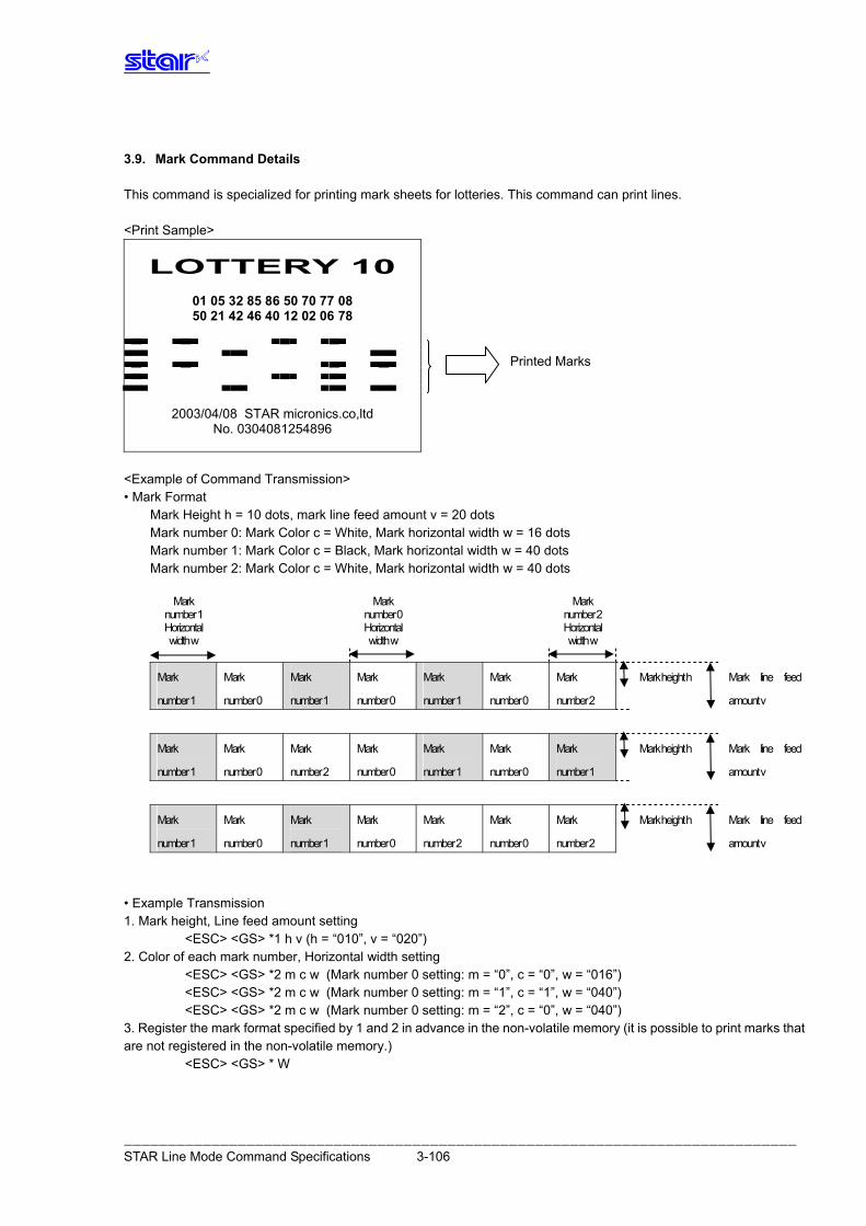
3.9. Mark Command Details This command is specialized for printing mark sheets for lotteries. This command can print lines. <Print Sample>
LOTTERY 10
01 05 32 85 86 50 70 77 08 50 21 42 46 40 12 02 06 78
Printed Marks
2003/04/08 STAR micronics.co,ltd No. 0304081254896
<Example of Command Transmission> • Mark Format
Mark Height h = 10 dots, mark line feed amount v = 20 dots Mark number 0: Mark Color c = White, Mark horizontal width w = 16 dots Mark number 1: Mark Color c = Black, Mark horizontal width w = 40 dots Mark number 2: Mark Color c = White, Mark horizontal width w = 40 dots
Mark
number 1 Horizontal width w
Mark number 0 Horizontal width w
Mark number 2
Horizontal width w
Mark Mark Mark Mark
number 0
Mark
number 0
Mark
number 0
Mark
number 2
Mark height h
number 1 number 1 number 1
Mark line feed
amount v
Mark
number 0
Mark
number 2
Mark
number 0
Mark
number 0
Mark height h Mark
number 1
Mark
number 1
Mark
number 1
Mark line feed
amount v
Mark Mark Mark
number 0
Mark
number 0
Mark
number 2
Mark
number 0
Mark
number 2
Mark height h
number 1 number 1
Mark line feed
amount v
• Example Transmission 1. Mark height, Line feed amount setting <ESC> <GS> *1 h v (h = “010”, v = “020”) 2. Color of each mark number, Horizontal width setting <ESC> <GS> *2 m c w (Mark number 0 setting: m = “0”, c = “0”, w = “016”) <ESC> <GS> *2 m c w (Mark number 0 setting: m = “1”, c = “1”, w = “040”) <ESC> <GS> *2 m c w (Mark number 0 setting: m = “2”, c = “0”, w = “040”) 3. Register the mark format specified by 1 and 2 in advance in the non-volatile memory (it is possible to print marks that are not registered in the non-volatile memory.) <ESC> <GS> * W
――――――――――――――――――――――――――――――――――――――――――――――――――――――――――――――――――――――――――――― STAR Line Mode Command Specifications 3-106
4. Printing Marks <ESC><GS> * 0 n m1 m2 m3 m4 m5 m6 m7 (n=”007”, m1=”1”, m2=”0”, m3=”1”, m4=”0”, m5=”1”, m6=”0”, m7=”2”) <ESC><GS> * 0 n m1 m2 m3 m4 m5 m6 m7 (n=”007”, m1=”1”, m2=”0”, m3=”2”, m4=”0”, m5=”1”, m6=”0”, m7=”1”) <ESC><GS> * 0 n m1 m2 m3 m4 m5 m6 m7 (n=”007”, m1=”1”, m2=”0”, m3=”1”, m4=”0”, m5=”2”, m6=”0”, m7=”2”)
――――――――――――――――――――――――――――――――――――――――――――――――――――――――――――――――――――――――――――― STAR Line Mode Command Specifications 3-107
ESC GS * 0 n m1 m2 m3 … mk [Name] Print mark [Code] ASCII ESC GS * 0 n m1 m2 m3 … mk Hex. 1B 1D 2A 30 n m1 m2 m3 … mk Decimal 27 29 42 48 n m1 m2 m3 … mk [Defined Area] “001” ≤ n ≤ ”255” “0” ≤ m ≤ ”9” k = n [Initial Value] - - - [Function] Prints the mark number specified by m, based on the mark format (mark height, mark line feed
amount, each mark color, and each mark horizontal width) that is preset. n indicates the number of marks to print; If the number of marks is 10 (m1 to m10), n = “010.” m specifies the mark number to print. n and m are ASCII character strings that are represented by decimals; They are composed of
character codes “0” to “9.” This command is ignored if there is print data in the image buffer. Therefore, other characters
cannot be included (characters, bit images, bar codes, etc.). If there is no mark specified in the remaining print region, the number of bytes specified by n are
discarded. Also, if the value of n is out of the defined range, subsequent data are processed as normal data. This command is affected by position alignment, left margin, moved position, positions such as
horizontal tab and upside down printing. Invalid in page mode.
――――――――――――――――――――――――――――――――――――――――――――――――――――――――――――――――――――――――――――― STAR Line Mode Command Specifications 3-108
ESC GS * 1 h v Name] Specify mark height and line feed [Code] ASCII ESC GS * 1 h v Hex. 1B 1D 2A 31 h v Decimal 27 29 42 49 h v [Defined Area] “001” ≤ h ≤ ”255” “001” ≤ v ≤ ”255” h ≤ v [Initial Value] Non-volatile memory [Function] Specifies mark height and line feed amount h is the mark height (number of dots); v is the line feed amount for the mark (number of dots) h and v are ASCII character strings that are represented by decimals; They are composed of
character codes “0” to “9.” If a small line feed amount is specified, missing print can occur, so more than v = 16 dots is
recommended. Invalid in page mode.
ESC GS * 2 m c w [Name] Specify mark color and mark horizontal width for each mark number [Code] ASCII ESC GS * 2 m c w Hex. 1B 1D 2A 32 m c w Decimal 27 29 42 50 m c w [Defined Area] “0” ≤ m ≤ ”9” “0” ≤ c ≤ ”1” “001” ≤ w ≤ ”999” [Initial Value] Non-volatile memory [Function] Specifies mark color and mark horizontal width for each mark number. m specifies the mark number. c specifies the mark color. w specifies the mark horizontal width (number of dots). If w exceeds the currently set print region, this command is ignored. m, c and w are ASCII character strings that are represented by decimals; They are composed of
character codes “0” to “9.” Invalid in page mode.
c Mark Color “0” (48) White “1” (49) Black
――――――――――――――――――――――――――――――――――――――――――――――――――――――――――――――――――――――――――――― STAR Line Mode Command Specifications 3-109
ESC GS * W [Name] Register mark format to non-volatile memory [Code] ASCII ESC GS * W Hex. 1B 1D 2A 57 Decimal 27 29 42 87 [Defined Area] - - - [Initial Value] - - - [Function] Registers the mark format (mark height, mark line feed amount, each mark color, and each mark
horizontal width) to the non-volatile memory. After registering to the non-volatile memory, the printer is reset. Invalid in page mode.
ESC GS * C [Name] Initialize mark format in the non-volatile memory [Code] ASCII ESC GS * C Hex. 1B 1D 2A 43 Decimal 27 29 42 67 [Defined Area] - - - [Initial Value] - - - [Function] Initializes the registered mark format (mark height, mark line feed amount, each mark color, and
each mark horizontal width) in the non-volatile memory. After initialization, the printer is reset. Initial Value of the Mark Format • Mark Height:: “016” 16 dots • Mark line feed amount:: “032” 32 dots • Mark color: “0” (White → All mark numbers) • Mark horizontal width: “080” 80 dots → All mark numbers) Invalid in page mode.
――――――――――――――――――――――――――――――――――――――――――――――――――――――――――――――――――――――――――――― STAR Line Mode Command Specifications 3-110
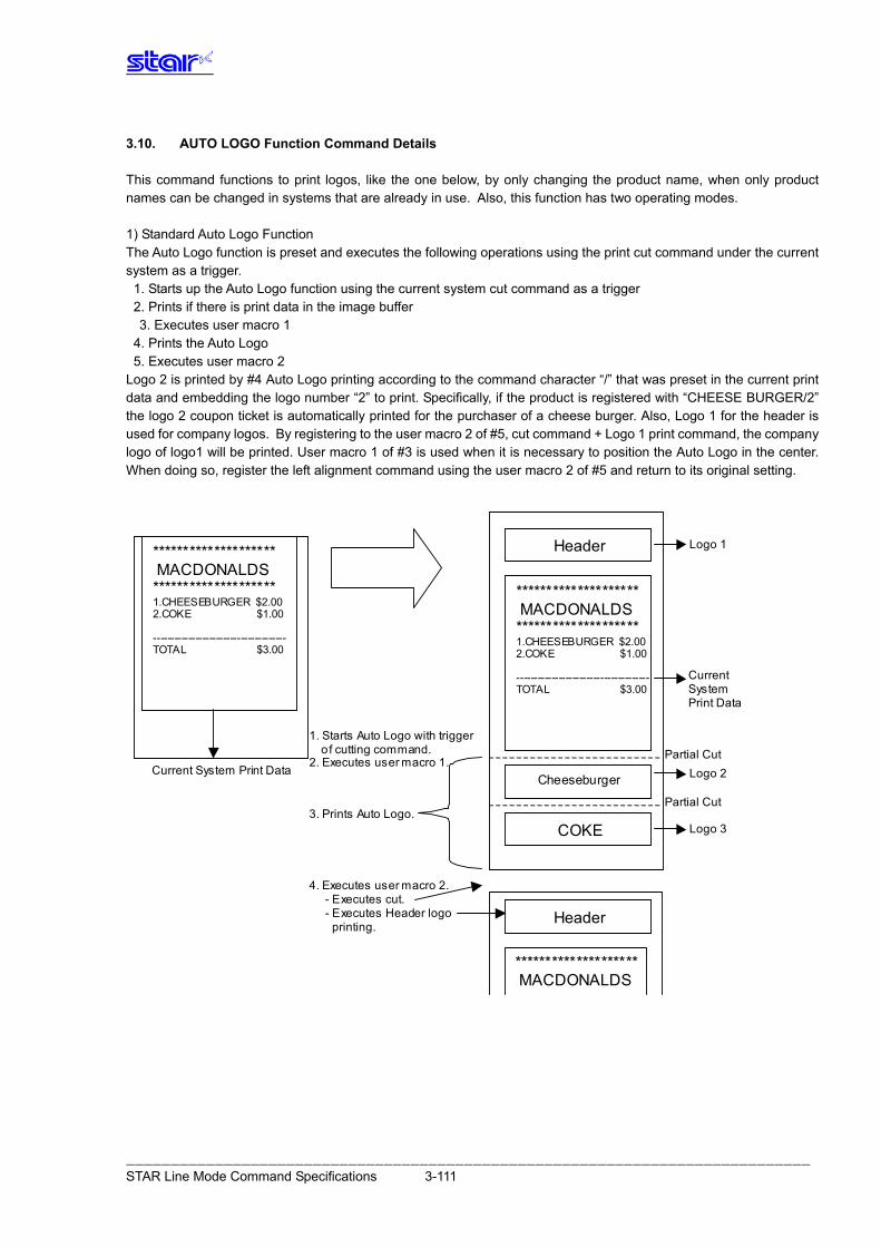
3.10. AUTO LOGO Function Command Details This command functions to print logos, like the one below, by only changing the product name, when only product names can be changed in systems that are already in use. Also, this function has two operating modes. 1) Standard Auto Logo Function The Auto Logo function is preset and executes the following operations using the print cut command under the current system as a trigger. 1. Starts up the Auto Logo function using the current system cut command as a trigger 2. Prints if there is print data in the image buffer
3. Executes user macro 1 4. Prints the Auto Logo 5. Executes user macro 2 Logo 2 is printed by #4 Auto Logo printing according to the command character “/” that was preset in the current print data and embedding the logo number “2” to print. Specifically, if the product is registered with “CHEESE BURGER/2” the logo 2 coupon ticket is automatically printed for the purchaser of a cheese burger. Also, Logo 1 for the header is used for company logos. By registering to the user macro 2 of #5, cut command + Logo 1 print command, the company logo of logo1 will be printed. User macro 1 of #3 is used when it is necessary to position the Auto Logo in the center. When doing so, register the left alignment command using the user macro 2 of #5 and return to its original setting.
***************
MACDONALDS
*************** 1.CHEESBUGER $2.00
2.COKE $1.00
----------------------
TOTAL $3.00
******************** MACDONALDS ******************** 1.CHEESEBURGER $2.00 2.COKE $1.00 -------------------------------------- TOTAL $3.00
******************** MACDONALDS ******************** 1.CHEESEBURGER $2.00 2.COKE $1.00 -------------------------------------- TOTAL $3.00
Header
Header
COKE
Cheeseburger
Logo 1
Logo 2
Logo 3
Current System Print Data
Current System Print Data
Partial Cut
Partial Cut
Header
******************** MACDONALDS
1. Starts Auto Logo with trigger o f cutting command. 2. Executes user macro 1.
4. Executes user macro 2. - Executes cut. - Executes Header logo printing.
3. Prints Auto Logo.
――――――――――――――――――――――――――――――――――――――――――――――――――――――――――――――――――――――――――――― STAR Line Mode Command Specifications 3-111
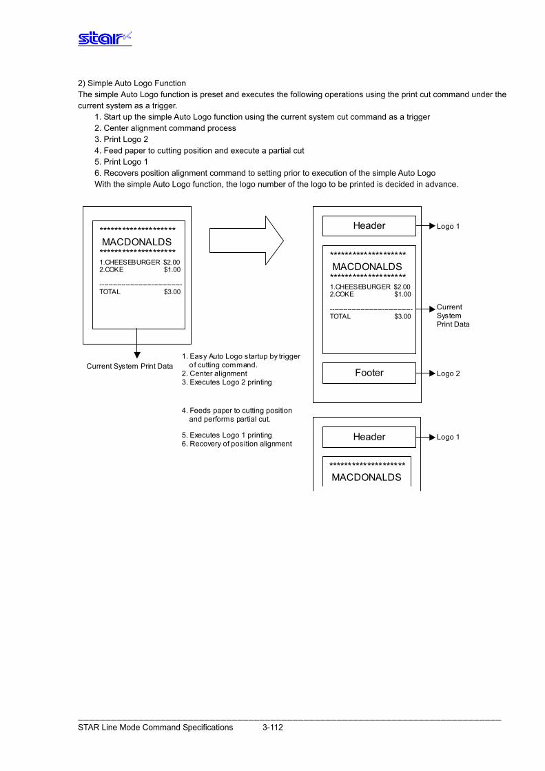
2) Simple Auto Logo Function The simple Auto Logo function is preset and executes the following operations using the print cut command under the current system as a trigger.
1. Start up the simple Auto Logo function using the current system cut command as a trigger 2. Center alignment command process 3. Print Logo 2 4. Feed paper to cutting position and execute a partial cut 5. Print Logo 1 6. Recovers position alignment command to setting prior to execution of the simple Auto Logo With the simple Auto Logo function, the logo number of the logo to be printed is decided in advance.
***************
MACDONALDS
*************** 1.CHEESBUGER $2.00
2.COKE $1.00
----------------------
TOTAL $3.00
******************** MACDONALDS ******************** 1.CHEESEBURGER $2.00 2.COKE $1.00 -------------------------------------- TOTAL $3.00
******************** MACDONALDS ******************** 1.CHEESEBURGER $2.00 2.COKE $1.00 -------------------------------------- TOTAL $3.00
Header Logo 1
Logo 1
Current System Print Data
Current System Print Data
Header
******************** MACDONALDS
4. Feeds paper to cutting position and performs partial cut.
5. Executes Logo 1 printing 6. Recovery of position alignment
Footer Logo 2
1. Easy Auto Logo startup by trigger o f cutting command. 2. Center alignment 3. Executes Logo 2 printing
――――――――――――――――――――――――――――――――――――――――――――――――――――――――――――――――――――――――――――― STAR Line Mode Command Specifications 3-112
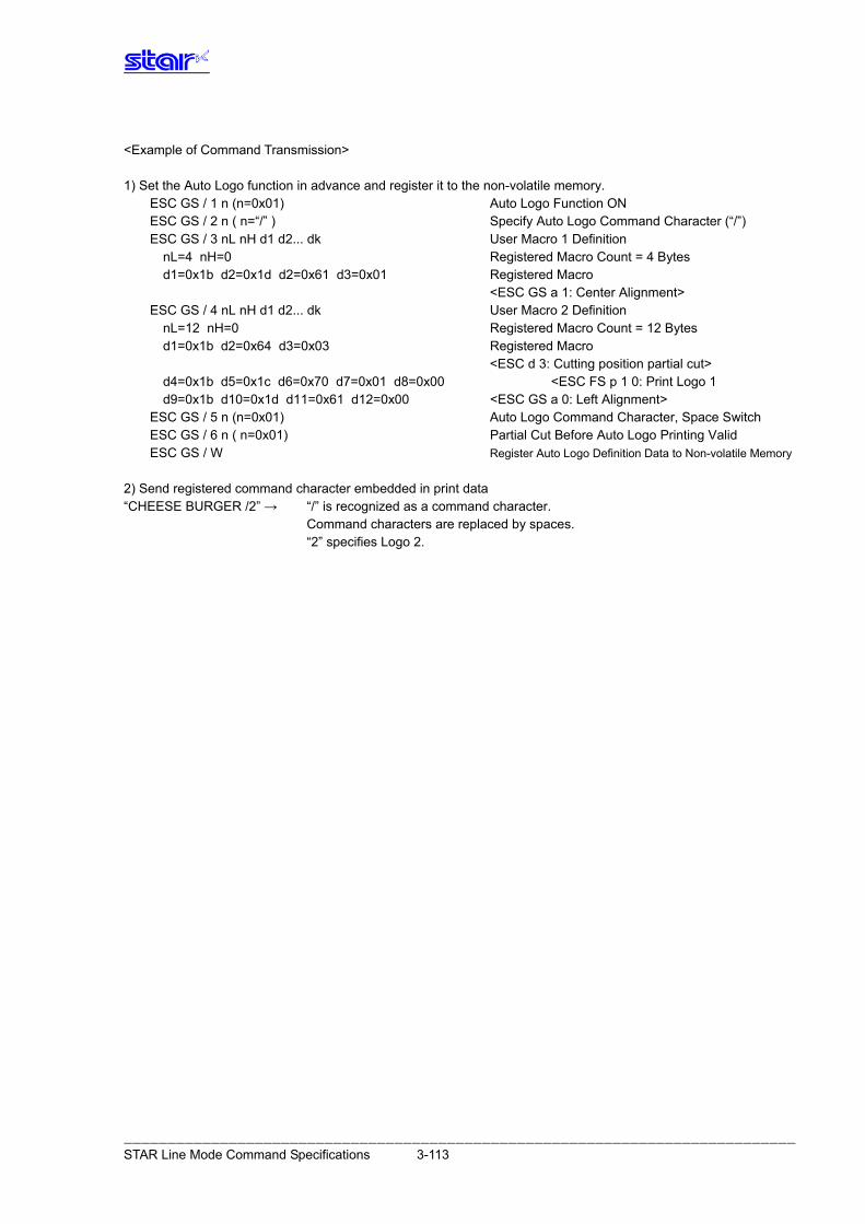
<Example of Command Transmission> 1) Set the Auto Logo function in advance and register it to the non-volatile memory.
ESC GS / 1 n (n=0x01) Auto Logo Function ON ESC GS / 2 n ( n=“/” ) Specify Auto Logo Command Character (“/”) ESC GS / 3 nL nH d1 d2... dk User Macro 1 Definition
nL=4 nH=0 Registered Macro Count = 4 Bytes d1=0x1b d2=0x1d d2=0x61 d3=0x01 Registered Macro <ESC GS a 1: Center Alignment>
ESC GS / 4 nL nH d1 d2... dk User Macro 2 Definition nL=12 nH=0 Registered Macro Count = 12 Bytes d1=0x1b d2=0x64 d3=0x03 Registered Macro <ESC d 3: Cutting position partial cut> d4=0x1b d5=0x1c d6=0x70 d7=0x01 d8=0x00 <ESC FS p 1 0: Print Logo 1 d9=0x1b d10=0x1d d11=0x61 d12=0x00 <ESC GS a 0: Left Alignment>
ESC GS / 5 n (n=0x01) Auto Logo Command Character, Space Switch ESC GS / 6 n ( n=0x01) Partial Cut Before Auto Logo Printing Valid ESC GS / W Register Auto Logo Definition Data to Non-volatile Memory
2) Send registered command character embedded in print data “CHEESE BURGER /2” → “/” is recognized as a command character. Command characters are replaced by spaces. “2” specifies Logo 2.
――――――――――――――――――――――――――――――――――――――――――――――――――――――――――――――――――――――――――――― STAR Line Mode Command Specifications 3-113
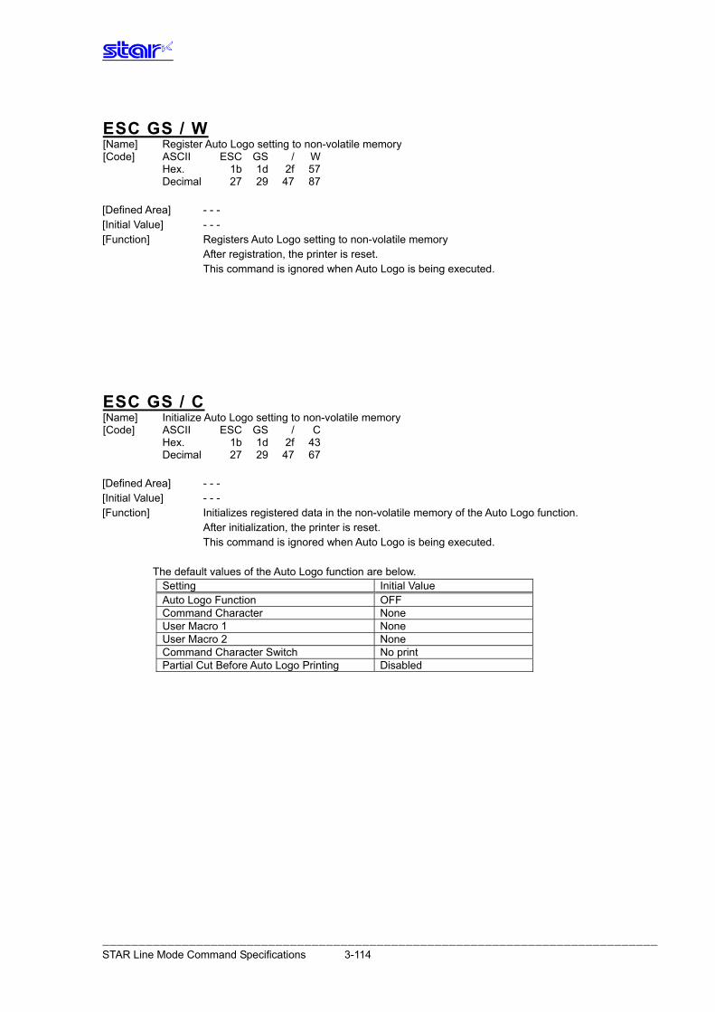
ESC GS / W [Name] Register Auto Logo setting to non-volatile memory [Code] ASCII ESC GS / W Hex. 1b 1d 2f 57 Decimal 27 29 47 87 [Defined Area] - - - [Initial Value] - - - [Function] Registers Auto Logo setting to non-volatile memory After registration, the printer is reset. This command is ignored when Auto Logo is being executed.
ESC GS / C [Name] Initialize Auto Logo setting to non-volatile memory [Code] ASCII ESC GS / C Hex. 1b 1d 2f 43 Decimal 27 29 47 67 [Defined Area] - - - [Initial Value] - - - [Function] Initializes registered data in the non-volatile memory of the Auto Logo function.
After initialization, the printer is reset. This command is ignored when Auto Logo is being executed.
The default values of the Auto Logo function are below.
Setting Initial Value Auto Logo Function OFF Command Character None User Macro 1 None User Macro 2 None Command Character Switch No print Partial Cut Before Auto Logo Printing Disabled
――――――――――――――――――――――――――――――――――――――――――――――――――――――――――――――――――――――――――――― STAR Line Mode Command Specifications 3-114
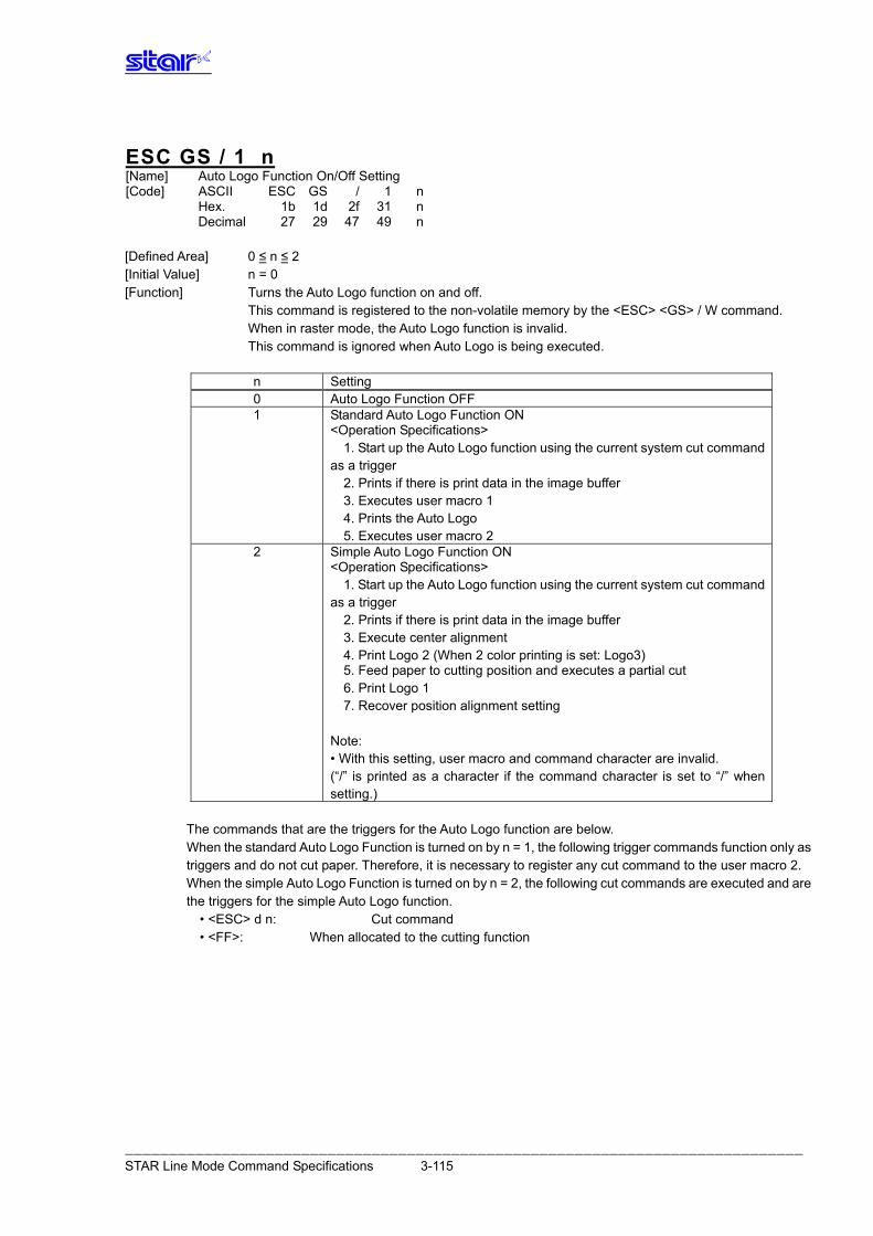
ESC GS / 1 n [Name] Auto Logo Function On/Off Setting [Code] ASCII ESC GS / 1 n Hex. 1b 1d 2f 31 n Decimal 27 29 47 49 n [Defined Area] 0 ≤ n ≤ 2 [Initial Value] n = 0 [Function] Turns the Auto Logo function on and off.
This command is registered to the non-volatile memory by the <ESC> <GS> / W command. When in raster mode, the Auto Logo function is invalid.
This command is ignored when Auto Logo is being executed.
n Setting 0 Auto Logo Function OFF 1 Standard Auto Logo Function ON
<Operation Specifications> 1. Start up the Auto Logo function using the current system cut command
as a trigger 2. Prints if there is print data in the image buffer 3. Executes user macro 1 4. Prints the Auto Logo 5. Executes user macro 2
2 Simple Auto Logo Function ON <Operation Specifications>
1. Start up the Auto Logo function using the current system cut command as a trigger
2. Prints if there is print data in the image buffer 3. Execute center alignment 4. Print Logo 2 (When 2 color printing is set: Logo3) 5. Feed paper to cutting position and executes a partial cut 6. Print Logo 1 7. Recover position alignment setting
Note: • With this setting, user macro and command character are invalid. (“/” is printed as a character if the command character is set to “/” when setting.)
The commands that are the triggers for the Auto Logo function are below.
When the standard Auto Logo Function is turned on by n = 1, the following trigger commands function only as triggers and do not cut paper. Therefore, it is necessary to register any cut command to the user macro 2. When the simple Auto Logo Function is turned on by n = 2, the following cut commands are executed and are the triggers for the simple Auto Logo function.
• <ESC> d n: Cut command • <FF>: When allocated to the cutting function
――――――――――――――――――――――――――――――――――――――――――――――――――――――――――――――――――――――――――――― STAR Line Mode Command Specifications 3-115
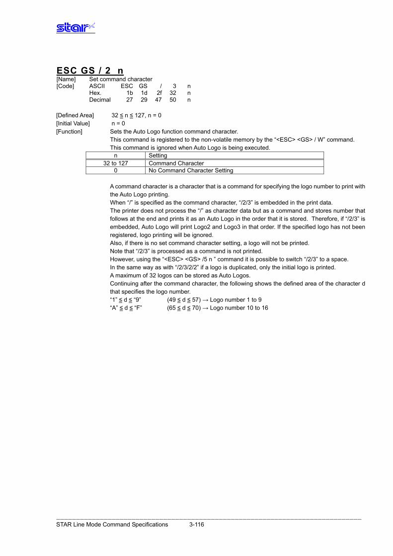
ESC GS / 2 n [Name] Set command character [Code] ASCII ESC GS / 3 n Hex. 1b 1d 2f 32 n Decimal 27 29 47 50 n [Defined Area] 32 ≤ n ≤ 127, n = 0 [Initial Value] n = 0 [Function] Sets the Auto Logo function command character. This command is registered to the non-volatile memory by the “<ESC> <GS> / W” command. This command is ignored when Auto Logo is being executed.
n Setting 32 to 127 Command Character
0 No Command Character Setting A command character is a character that is a command for specifying the logo number to print with
the Auto Logo printing. When “/” is specified as the command character, “/2/3” is embedded in the print data. The printer does not process the “/” as character data but as a command and stores number that
follows at the end and prints it as an Auto Logo in the order that it is stored. Therefore, if “/2/3” is embedded, Auto Logo will print Logo2 and Logo3 in that order. If the specified logo has not been registered, logo printing will be ignored.
Also, if there is no set command character setting, a logo will not be printed. Note that “/2/3” is processed as a command is not printed. However, using the “<ESC> <GS> /5 n ” command it is possible to switch “/2/3” to a space. In the same way as with “/2/3/2/2” if a logo is duplicated, only the initial logo is printed. A maximum of 32 logos can be stored as Auto Logos. Continuing after the command character, the following shows the defined area of the character d
that specifies the logo number. “1” ≤ d ≤ “9” (49 ≤ d ≤ 57) → Logo number 1 to 9 “A” ≤ d ≤ “F” (65 ≤ d ≤ 70) → Logo number 10 to 16
――――――――――――――――――――――――――――――――――――――――――――――――――――――――――――――――――――――――――――― STAR Line Mode Command Specifications 3-116
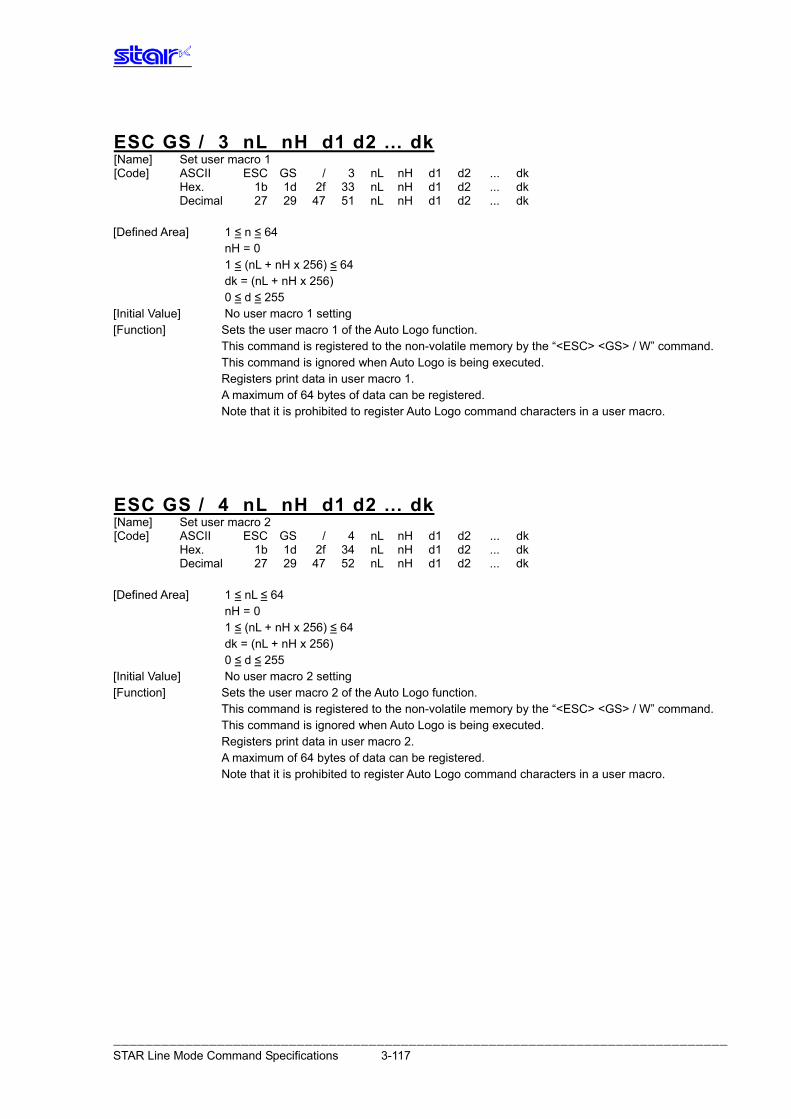
ESC GS / 3 nL nH d1 d2 … dk [Name] Set user macro 1 [Code] ASCII ESC GS / 3 nL nH d1 d2 ... dk Hex. 1b 1d 2f 33 nL nH d1 d2 ... dk Decimal 27 29 47 51 nL nH d1 d2 ... dk [Defined Area] 1 ≤ n ≤ 64
nH = 0 1 ≤ (nL + nH x 256) ≤ 64 dk = (nL + nH x 256) 0 ≤ d ≤ 255
[Initial Value] No user macro 1 setting [Function] Sets the user macro 1 of the Auto Logo function. This command is registered to the non-volatile memory by the “<ESC> <GS> / W” command. This command is ignored when Auto Logo is being executed. Registers print data in user macro 1. A maximum of 64 bytes of data can be registered. Note that it is prohibited to register Auto Logo command characters in a user macro.
ESC GS / 4 nL nH d1 d2 … dk [Name] Set user macro 2 [Code] ASCII ESC GS / 4 nL nH d1 d2 ... dk Hex. 1b 1d 2f 34 nL nH d1 d2 ... dk Decimal 27 29 47 52 nL nH d1 d2 ... dk [Defined Area] 1 ≤ nL ≤ 64
nH = 0 1 ≤ (nL + nH x 256) ≤ 64 dk = (nL + nH x 256) 0 ≤ d ≤ 255
[Initial Value] No user macro 2 setting [Function] Sets the user macro 2 of the Auto Logo function. This command is registered to the non-volatile memory by the “<ESC> <GS> / W” command. This command is ignored when Auto Logo is being executed. Registers print data in user macro 2. A maximum of 64 bytes of data can be registered. Note that it is prohibited to register Auto Logo command characters in a user macro.
――――――――――――――――――――――――――――――――――――――――――――――――――――――――――――――――――――――――――――― STAR Line Mode Command Specifications 3-117
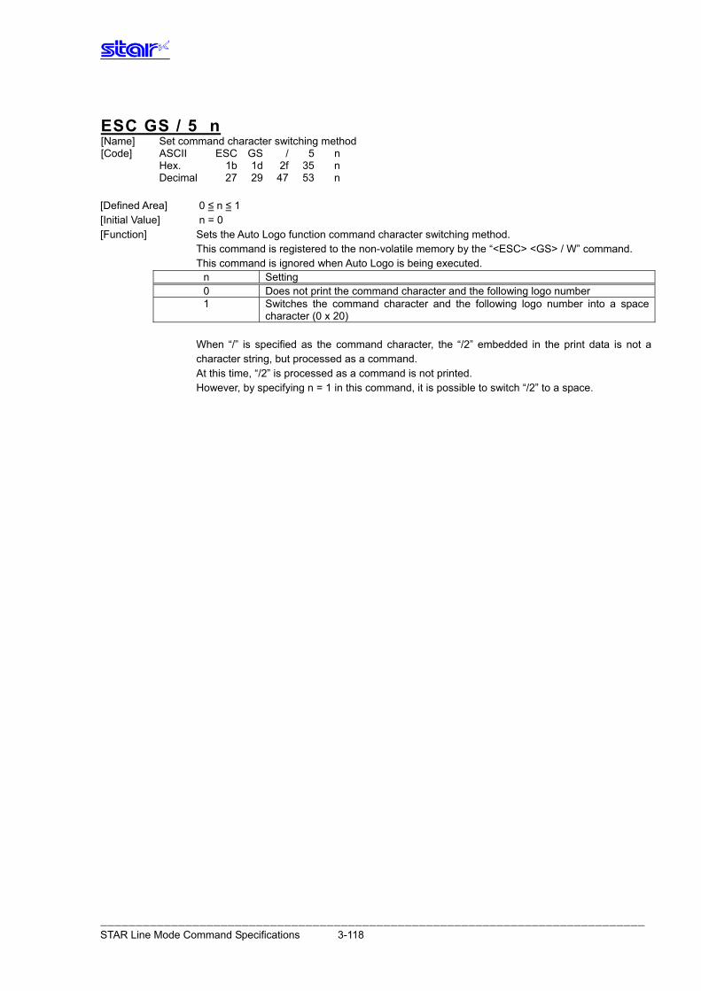
ESC GS / 5 n [Name] Set command character switching method [Code] ASCII ESC GS / 5 n Hex. 1b 1d 2f 35 n Decimal 27 29 47 53 n [Defined Area] 0 ≤ n ≤ 1 [Initial Value] n = 0 [Function] Sets the Auto Logo function command character switching method. This command is registered to the non-volatile memory by the “<ESC> <GS> / W” command. This command is ignored when Auto Logo is being executed.
n Setting 0 Does not print the command character and the following logo number 1 Switches the command character and the following logo number into a space
character (0 x 20) When “/” is specified as the command character, the “/2” embedded in the print data is not a
character string, but processed as a command. At this time, “/2” is processed as a command is not printed. However, by specifying n = 1 in this command, it is possible to switch “/2” to a space.
――――――――――――――――――――――――――――――――――――――――――――――――――――――――――――――――――――――――――――― STAR Line Mode Command Specifications 3-118
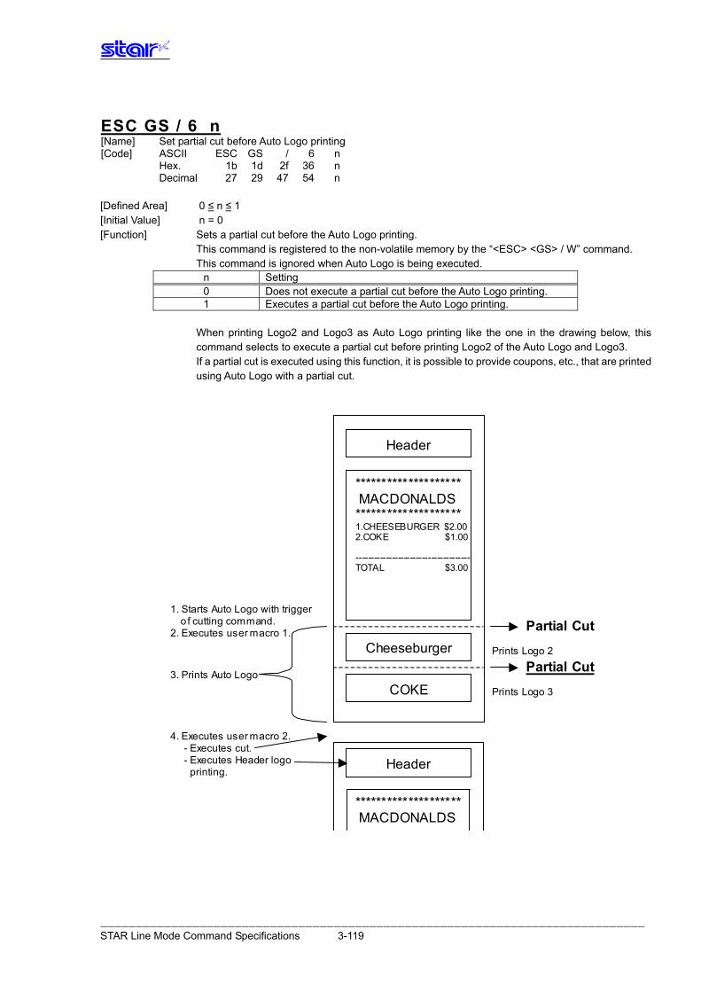
ESC GS / 6 n [Name] Set partial cut before Auto Logo printing [Code] ASCII ESC GS / 6 n Hex. 1b 1d 2f 36 n Decimal 27 29 47 54 n [Defined Area] 0 ≤ n ≤ 1 [Initial Value] n = 0 [Function] Sets a partial cut before the Auto Logo printing. This command is registered to the non-volatile memory by the “<ESC> <GS> / W” command. This command is ignored when Auto Logo is being executed.
n Setting 0 Does not execute a partial cut before the Auto Logo printing. 1 Executes a partial cut before the Auto Logo printing.
When printing Logo2 and Logo3 as Auto Logo printing like the one in the drawing below, this
command selects to execute a partial cut before printing Logo2 of the Auto Logo and Logo3. If a partial cut is executed using this function, it is possible to provide coupons, etc., that are printed
using Auto Logo with a partial cut.
***************
MACDONALDS
*************** 1.CHEESBUGER $2.00
2.COKE $1.00
----------------------
TOTAL $3.00
******************** MACDONALDS ******************** 1.CHEESEBURGER $2.00 2.COKE $1.00 -------------------------------------- TOTAL $3.00
Header
Header
COKE
Cheeseburger Prints Logo 2
Prints Logo 3
Partial Cut
Partial Cut
Header
******************** MACDONALDS
1. Starts Auto Logo with trigger o f cutting command. 2. Executes user macro 1.
4. Executes user macro 2. - Executes cut. - Executes Header logo printing.
3. Prints Auto Logo
――――――――――――――――――――――――――――――――――――――――――――――――――――――――――――――――――――――――――――― STAR Line Mode Command Specifications 3-119
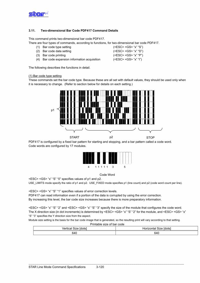
3.11. Two-dimensional Bar Code PDF417 Command Details This command prints two-dimensional bar code PDF417. There are four types of commands, according to functions, for two-dimensional bar code PDF417.
(1) Bar code type setting (<ESC> <GS> “x” “S”) (2) Bar code data setting (<ESC> <GS> “x” “D”) (3) Bar code printing (<ESC> <GS> “x” “P”) (4) Bar code expansion information acquisition (<ESC> <GS> “x” “I”)
The following describes the functions in detail.
(1) Bar code type setting These commands set the bar code type. Because these are all set with default values, they should be used only when it is necessary to change. (Refer to section below for details on each setting.) PDF417 is configured by a fixed bar pattern for starting and stopping, and a bar pattern called a code word. Code words are configured by 17 modules.
Code Word
<ESC> <GS> “x” “S” “0” specifies values of p1 and p2. USE_LIMITS mode specify the ratio of p1 and p2. USE_FIXED mode specifies p1 (line count) and p2 (code word count per line). <ESC> <GS> “x” “S” “1” specifies values of error correction levels. PDF417 can read information even if a portion of the data is corrupted by using the error correction. By increasing this level, the bar code size increases because there is more preparatory information. <ESC> <GS> “x” “S” “2” and <ESC> <GS> “x” “S” “3” specify the size of the module that configures the code word. The X direction size (in dot increments) is determined by <ESC> <GS> “x” “S” “2” for the module, and <ESC> <GS> “x” “S” “3” specifies the Y direction size from the aspect. Module size setting is the basis for the bar code image that is generated, so the resulting print will vary according to that setting.
Printable size of bar code Vertical Size [dots] Horizontal Size [dots]
640 640
p1
p2 START STOP
4 1 1 1 1 1 3 5
――――――――――――――――――――――――――――――――――――――――――――――――――――――――――――――――――――――――――――― STAR Line Mode Command Specifications 3-120
The settings above are set individually, so the errors described below may be generated even if there is no particular problem in those settings. In such case, if the bar code is generated the (3) print command (<ESC> <GS> “x” “P”) is ignored. • Error is generated when generating a bar code, due to the combination of the bar code setting commands. • The bar code data that is generated exceeds the printable size of PDF417. • Print data exceeds the currently set print region. It is recommended to use (4) Bar code expansion information acquisition (<ESC> <GS> “x” “I”) as a means for checking these errors prior to printing. (2) Bar code data setting command This command sets the print data of the bar code. (3) Bar code print command This command prints the bar code according to the settings of (1) and (2). (4) Bar code expansion information acquisition This command checks whether it is possible to print the bar code according to the settings of (1) and (2). - Precautions for use of commands -
• Unless the following operations are performed, the setting values are maintained for (1) and (2). • Sending of new setting commands • Sending an initializing command (<ESC> @, <CAN>) • The power is turned off • Sending (3) and (4) when needed • Printing • When printing, position shifting according to the horizontal tab, absolute position specification, relative position specification, and position alignment is valid. • Upside-down printing and two-color printing are possible. • When a bar code is printed, always verify it by actual use.
Send the command transmission example last. 1. Bar code type setting
<ESC> <GS> “x” “S” “0” 0 2 3: Sets the bar code size to USE_LIMITS = 2:3 <ESC> <GS> “x” “S” “1” 3: Sets ECC level to 3 <ESC> <GS> “x” “S” “2” 3: Sets the module X direction size to 3 dots <ESC> <GS> “x” “S” “3” 3: Sets module aspect ratio to 3
2. Bar code data setting
<ESC> <GS> “x” “D” 10 0 “0123456789”: Sets the bar code data 3. Printing bar code To verify whether printing is possible with the current settings, check the bar code expansion information
<ESC> <GS> “x” “I”: Bar code expansion information check <ESC> <GS> “x” “P”: Print
――――――――――――――――――――――――――――――――――――――――――――――――――――――――――――――――――――――――――――― STAR Line Mode Command Specifications 3-121
ESC GS x S 0 n p1 p2 [Name] Set PDF417 bar code size [Code] ASCII ESC GS x S 0 n p1 p2
Hex. 1B 1D 78 53 30 n p1 p2 Decimal 27 29 120 83 48 n p1 p2 [Defined Area] n = 0, 1
When n = 0: 1 ≤ p1 ≤ 99, 1 ≤ p2 ≤ 99 When n = 1: p1 = 0 or 3 ≤ p1 ≤ 90, p2 = 0 or 1 ≤ p2 ≤ 30
(However, this excludes p1 = p2 = 0) [Initial Value] n = 0, p1 = 1, p2 = 2 [Function] Parameter details
n p1, p2 (Specify Method to Specify Bar Code Size) (Size Specification)
p1: p2: Proportions of Vertical (p1) and Horizontal (p2) 0 USE_LIMITS (Specify ratio of bar code horizontally and vertically)
However, p1: p2 = 1: 99 to 10 : 1 (p1/p2 = 0.01 to 10)
p1: Number of lines (0, 3 to 90), p2: Number of columns (0, 1 to 30)
1 USE_FIXED (Specifies number of lines and number of columns of bar code.) However, p1 * p2 ≤ 928
When either p1 or p2 specifies 0, it indicates that that setting value is variable.
Setting the bar code size using this command specifies the general size of the bar code. The size will automatically be corrected according to the other settings.
ESC GS x S 1 n [Name] Set PDF417 ECC (security level) [Code] ASCII ESC GS x S 1 n
Hex. 1B 1D 78 53 31 n Decimal 27 29 120 83 49 n [Defined Area] 0 ≤ n ≤ 8 [Initial Value] n = 1 [Function] Parameter details
• n: ECC level (0 to 8)
ESC GS x S 2 n [Name] Set PDF417 module X direction size [Code] ASCII ESC GS x S 2 n
Hex. 1B 1D 78 53 32 n Decimal 27 29 120 83 50 n [Defined Area] 1 ≤ n ≤ 10 [Initial Value] n = 2 [Function] Parameter details
• n: Sets the module X direction size (x-dim). Units: Dots It is recommended that 2 ≤ n when specifying using this command. When using with n = 1, check by actual use.
――――――――――――――――――――――――――――――――――――――――――――――――――――――――――――――――――――――――――――― STAR Line Mode Command Specifications 3-122
ESC GS x S 3 n [Name] Set PDF417 module aspect ratio [Code] ASCII ESC GS x S 3 n
Hex. 1B 1D 78 53 33 n Decimal 27 29 120 83 51 n [Defined Area] 1 ≤ n ≤ 10 [Initial Value] n = 3 [Function] Parameter details
• n: Sets the module aspect ratio (asp). The module Y direction size (x-dim x asp) is set using this command.
It is recommended that 2 ≤ n when specifying using this command. When using with n = 1, check by actual use.
ESC GS x D nL nH d1 d2 … dk [Name] Set PDF417 bar code data [Code] ASCII ESC GS x D nL nH d1 d2 … dk Hex. 1B 1D 78 44 nL nH d1 d2 … dk Decimal 27 29 120 68 nL nH d1 d2 … dk [Defined Area] 0 ≤ nL ≤ 255, 0 ≤ nH ≤ 255
1 ≤ (nL + nH x 256) ≤ 1024 0 ≤ d ≤ 255 1 ≤ k ≤ 1024
[Initial Value] --- [Function] Parameter details
• nL + nH x 256 : Bar code data count • dk : Bar code data (Maximum 1024 data)
When [nL + nH x 256] is outside of the definition, data of [nL + nH x 256] bytes is discarded.
ESC GS x P [Name] Print PDF417 bar code [Code] ASCII ESC GS x P Hex. 1B 1D 78 50 Decimal 27 29 120 80 [Defined Area] --- [Initial Value] --- [Function] Prints the bar code data. If there is unprinted data in the line buffer, this command is executed after printing that data in the
line buffer. Therefore, it is not possible to print with other data in the same line (characters, bit images, bar codes).
Also, this command is ignored if the following errors occur. • When an error is generated when generating a bar code, due to the combination of the bar code
setting commands • When the bar code data that is generated exceeds the printable size of PDF417 • When the print data exceeds the currently set print region When a bar code is printed, always verify it by actual use.
――――――――――――――――――――――――――――――――――――――――――――――――――――――――――――――――――――――――――――― STAR Line Mode Command Specifications 3-123
ESC GS x I [Name] Get PDF417 bar code expansion information [Code] ASCII ESC GS x I Hex. 1B 1D 78 49 Decimal 27 29 120 73
[Defined Area] --- [Initial Value] --- [Function] When printing a bar code with the current settings and at the print starting position using this
command, error information is sent to the printer. Therefore, it is possible to check whether it is possible to print before actually printing, by using this command.
If an error occurs, this command is discarded even if the print command (<ESC> <GS> “x” “P”) is sent.
If the following errors occur, “Error” information is sent to the printer. • When an error is generated when generating a bar code, due to the combination of the bar code
setting commands. • When the bar code data that is generated exceeds the printable size of PDF417. • When the print data exceeds the currently set print region
Transmission format: <ESC> <GS> “x” “I” n
n 0 No Error 1 Error
――――――――――――――――――――――――――――――――――――――――――――――――――――――――――――――――――――――――――――― STAR Line Mode Command Specifications 3-124
3.12. Details of the Print Starting Trigger Control Command This command is for models equipped with an expansion control function for page control of line unit commands, by controlling the image buffer by page.
ESC GS g 0 m n [Name] Print starting trigger [Code] ASCII ESC GS g 0 m n Hex. 1B 1D 67 30 m n Decimal 27 29 103 48 m n
[Defined Area] m = 0, n = 0 [Initial Value] --- [Function] Starts printing when there is unprinted data in the image buffer. It is prohibited to send this command while in the raster mode.
ESC GS g 1 m n [Name] Print starting timer [Code] ASCII ESC GS g 1 m n Hex. 1B 1D 67 31 m n Decimal 27 29 103 49 m n
[Defined Area] m = 0, 0 ≤ n ≤ 255 [Initial Value] Depends on the model [Function] Sets the print starting timer specified at n x 10 msec. The print starting timer starts measuring from the point where the print data reception stops, and
measures up to the set print starting timer. When the set print starting timer is reached, the printer starts printing if there is unprinted data in
the image buffer. It is prohibited to send this command while in the raster mode.
n Operating Mode 0 Print starting timer = initial value 1 to 255 Print starting timer n x 10 msec.
――――――――――――――――――――――――――――――――――――――――――――――――――――――――――――――――――――――――――――― STAR Line Mode Command Specifications 3-125
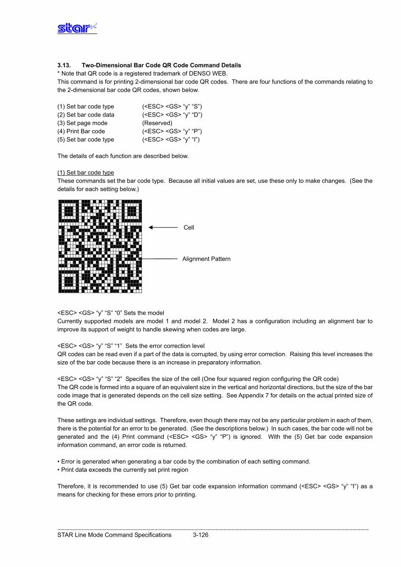
――――――――――――――――――――――――――――――――――――――――――――――――――――――――――――――――――――――――――――― STAR Line Mode Command Specifications 3-126
Cell
Alignment Pattern
3.13. Two-Dimensional Bar Code QR Code Command Details * Note that QR code is a registered trademark of DENSO WEB. This command is for printing 2-dimensional bar code QR codes. There are four functions of the commands relating to the 2-dimensional bar code QR codes, shown below. (1) Set bar code type (<ESC> <GS> “y” “S”) (2) Set bar code data (<ESC> <GS> “y” “D”) (3) Set page mode (Reserved) (4) Print Bar code (<ESC> <GS> “y” “P”) (5) Set bar code type (<ESC> <GS> “y” “I”) The details of each function are described below. (1) Set bar code type These commands set the bar code type. Because all initial values are set, use these only to make changes. (See the details for each setting below.)
<ESC> <GS> “y” “S” “0” Sets the model Currently supported models are model 1 and model 2. Model 2 has a configuration including an alignment bar to improve its support of weight to handle skewing when codes are large. <ESC> <GS> “y” “S” “1” Sets the error correction level QR codes can be read even if a part of the data is corrupted, by using error correction. Raising this level increases the size of the bar code because there is an increase in preparatory information. <ESC> <GS> “y” “S” “2” Specifies the size of the cell (One four squared region configuring the QR code) The QR code is formed into a square of an equivalent size in the vertical and horizontal directions, but the size of the bar code image that is generated depends on the cell size setting. See Appendix 7 for details on the actual printed size of the QR code. These settings are individual settings. Therefore, even though there may not be any particular problem in each of them, there is the potential for an error to be generated. (See the descriptions below.) In such cases, the bar code will not be generated and the (4) Print command (<ESC> <GS> “y” “P”) is ignored. With the (5) Get bar code expansion information command, an error code is returned. • Error is generated when generating a bar code by the combination of each setting command. • Print data exceeds the currently set print region Therefore, it is recommended to use (5) Get bar code expansion information command (<ESC> <GS> “y” “I”) as a means for checking for these errors prior to printing.
(2) Set bar code data This command sets the bar code print data. There are four types of data that can be set using QR codes. They are: numbers; English characters; binary; and Kanji. Furthermore, there are two types of data setting methods. One is to specify these along with the bar code data (data manual analysis), and the other is to specify only the bar code data (data automatic analysis). (3) Set page mode This command is not used. (4) Print Bar code This command prints bar codes based on the settings of (1) to (3). (5) Set bar code type This command confirms whether to print bar codes based on the settings of (1) to (3). = Precautions on using these commands = • The setting values for (1) to (3) are held unless any of the following operations are performed.
• Sending a new setting command • Sending an initialize command (<ESC> @, <CAN>) • Turning the power OFF
• When there is an error in sending a command with (2), the set data is cleared and the command itself is disabled. • (4) and (5) are sent when necessary. • Printing:
• When printing, position movement using specify absolute position, specify relative position, and align position are enabled. • Upside down printing and 2-color printing are possible.
• Printed bar codes should always be checked in an actual use.
――――――――――――――――――――――――――――――――――――――――――――――――――――――――――――――――――――――――――――― STAR Line Mode Command Specifications 3-127
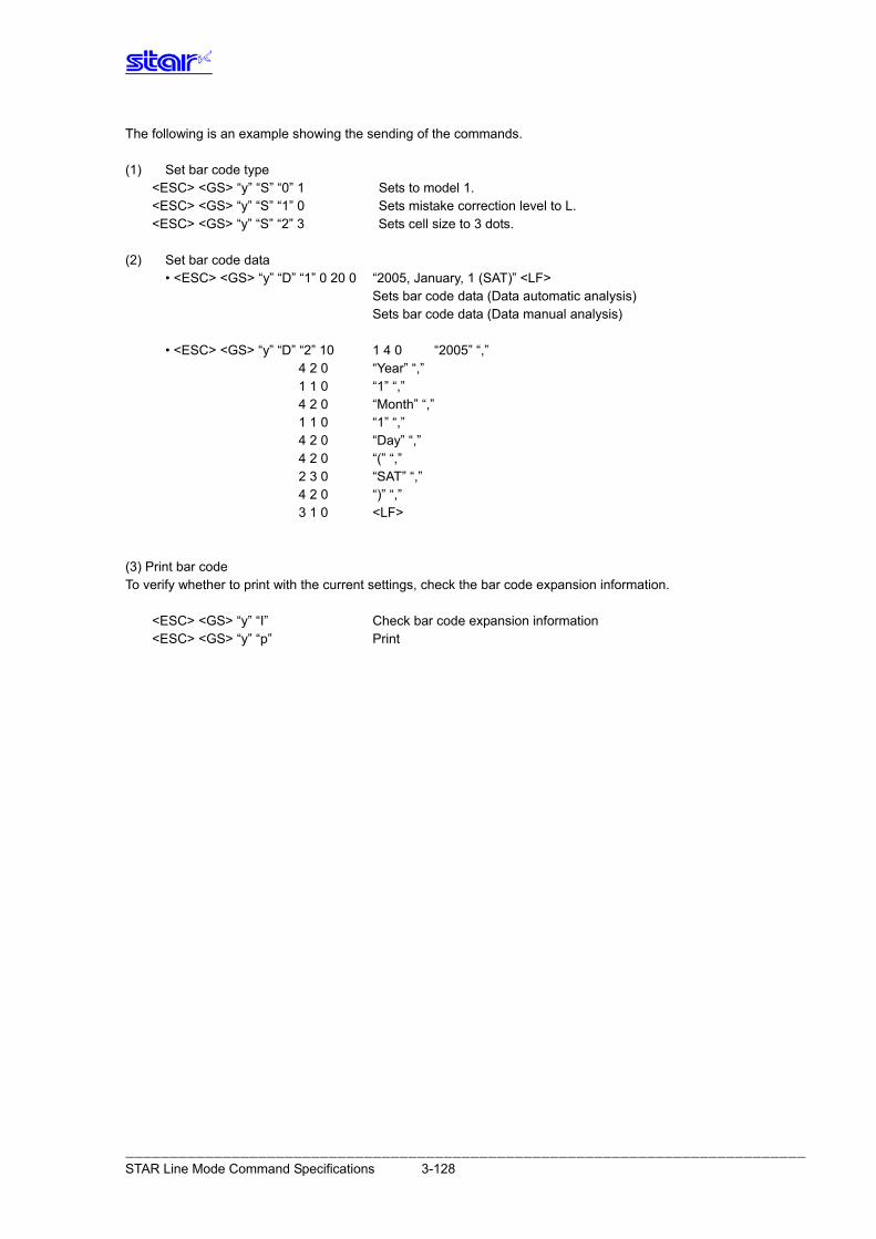
The following is an example showing the sending of the commands. (1) Set bar code type
<ESC> <GS> “y” “S” “0” 1 Sets to model 1. <ESC> <GS> “y” “S” “1” 0 Sets mistake correction level to L. <ESC> <GS> “y” “S” “2” 3 Sets cell size to 3 dots.
(2) Set bar code data • <ESC> <GS> “y” “D” “1” 0 20 0 “2005, January, 1 (SAT)” <LF> Sets bar code data (Data automatic analysis) Sets bar code data (Data manual analysis) • <ESC> <GS> “y” “D” “2” 10 1 4 0 “2005” “,” 4 2 0 “Year” “,” 1 1 0 “1” “,” 4 2 0 “Month” “,” 1 1 0 “1” “,” 4 2 0 “Day” “,” 4 2 0 “(” “,” 2 3 0 “SAT” “,” 4 2 0 “)” “,” 3 1 0 <LF> (3) Print bar code To verify whether to print with the current settings, check the bar code expansion information.
<ESC> <GS> “y” “I” Check bar code expansion information <ESC> <GS> “y” “p” Print
――――――――――――――――――――――――――――――――――――――――――――――――――――――――――――――――――――――――――――― STAR Line Mode Command Specifications 3-128
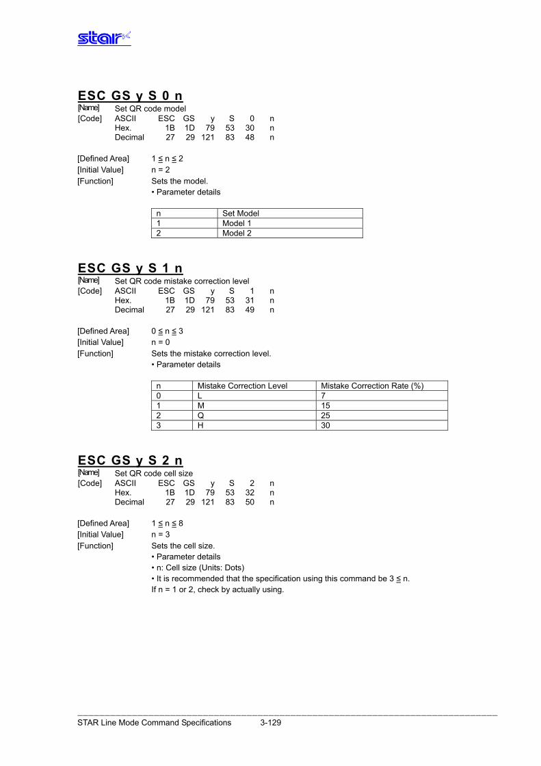
ESC GS y S 0 n [Name] Set QR code model [Code] ASCII ESC GS y S 0 n Hex. 1B 1D 79 53 30 n Decimal 27 29 121 83 48 n
[Defined Area] 1 ≤ n ≤ 2 [Initial Value] n = 2 [Function] Sets the model. • Parameter details
n Set Model 1 Model 1 2 Model 2
ESC GS y S 1 n [Name] Set QR code mistake correction level [Code] ASCII ESC GS y S 1 n Hex. 1B 1D 79 53 31 n Decimal 27 29 121 83 49 n
[Defined Area] 0 ≤ n ≤ 3 [Initial Value] n = 0 [Function] Sets the mistake correction level. • Parameter details
n Mistake Correction Level Mistake Correction Rate (%) 0 L 7 1 M 15 2 Q 25 3 H 30
ESC GS y S 2 n [Name] Set QR code cell size [Code] ASCII ESC GS y S 2 n Hex. 1B 1D 79 53 32 n Decimal 27 29 121 83 50 n
[Defined Area] 1 ≤ n ≤ 8 [Initial Value] n = 3 [Function] Sets the cell size. • Parameter details • n: Cell size (Units: Dots) • It is recommended that the specification using this command be 3 ≤ n. If n = 1 or 2, check by actually using.
――――――――――――――――――――――――――――――――――――――――――――――――――――――――――――――――――――――――――――― STAR Line Mode Command Specifications 3-129
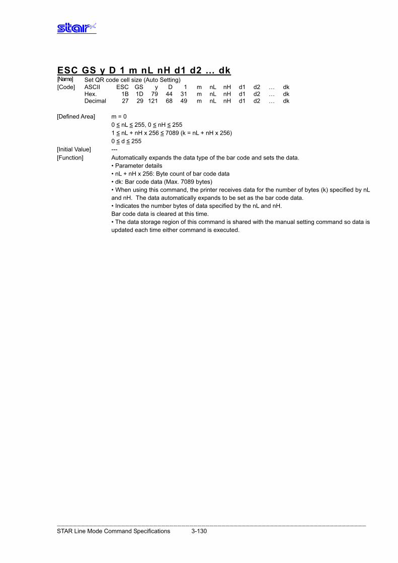
ESC GS y D 1 m nL nH d1 d2 … dk [Name] Set QR code cell size (Auto Setting) [Code] ASCII ESC GS y D 1 m nL nH d1 d2 … dk Hex. 1B 1D 79 44 31 m nL nH d1 d2 … dk Decimal 27 29 121 68 49 m nL nH d1 d2 … dk
[Defined Area] m = 0 0 ≤ nL ≤ 255, 0 ≤ nH ≤ 255 1 ≤ nL + nH x 256 ≤ 7089 (k = nL + nH x 256) 0 ≤ d ≤ 255 [Initial Value] --- [Function] Automatically expands the data type of the bar code and sets the data. • Parameter details • nL + nH x 256: Byte count of bar code data • dk: Bar code data (Max. 7089 bytes) • When using this command, the printer receives data for the number of bytes (k) specified by nL
and nH. The data automatically expands to be set as the bar code data. • Indicates the number bytes of data specified by the nL and nH. Bar code data is cleared at this time. • The data storage region of this command is shared with the manual setting command so data is
updated each time either command is executed.
――――――――――――――――――――――――――――――――――――――――――――――――――――――――――――――――――――――――――――― STAR Line Mode Command Specifications 3-130
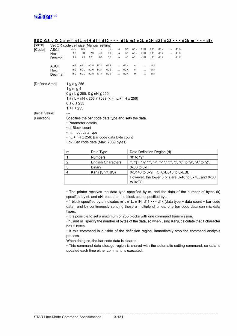
ESC GS y D 2 a m1 n1L n1H d11 d12 • • • d1k m2 n2L n2H d21 d22 • • • d2k ml • • • dlk [Name] Set QR code cell size (Manual setting) [Code] ASCII E S C G S y D 2 a m 1 n 1 L n 1 H d 11 d 1 2 … d 1 K
Hex. 1 B 1 D 7 9 4 4 3 2 a m 1 n 1 L n 1 H d 11 d 1 2 … d 1 K
Decimal 2 7 2 9 1 2 1 6 8 5 0 a m 1 n 1 L n 1 H d 11 d 1 2 … d 1 K
ASCII m 2 n 2 L n 2 H D 2 1 d 2 2 … d 2 K m l … d k l
Hex. m 2 n 2 L n 2 H D 2 1 d 2 2 … d 2 K m l … d k l
Decimal m 2 n 2 L n 2 H D 11 d 2 2 … d 2 K m l … d k l
[Defined Area] 1 ≤ a ≤ 255 1 ≤ m ≤ 4 0 ≤ nL ≤ 255, 0 ≤ nH ≤ 255 1 ≤ nL + nH x 256 ≤ 7089 (k = nL + nH x 256) 0 ≤ d ≤ 255 1 ≤ I ≤ 255 [Initial Value] --- [Function] Specifies the bar code data type and sets the data. • Parameter details • a: Block count • m: Input data type • nL + nH x 256: Bar code data byte count • dk: Bar code data (Max. 7089 bytes)
m Data Type Data Definition Region (d) 1 Numbers “0” to “9” 2 English Characters “”, “$”, “%” “*”, “+”, “-“ “.” “/”, “:”, “0” to “9”, “A” to “Z”, 3 Binary 0x00 to 0xFF 4 Kanji (Shift JIS) 0x8140 to 0x9FFC, 0xE040 to 0xEBBF However, the lower 8 bits are 0x40 to 0x7E, and 0x80
to 0xFC
• The printer receives the data type specified by m, and the data of the number of bytes (k) specified by nL and nH, based on the block count specified by a. • 1 block specified by a indicates m1, n1L, n1H, d11 • • • d1k (data type + data count + bar code data), and by continuously sending these a multiple of times, one bar code data can mix data types. • It is possible to set a maximum of 255 blocks with one command transmission. • nL and nH specify the number of bytes of the data, so when using Kanji, calculate that 1 character has 2 bytes. • If this command is outside of the definition region, immediately stop the command analysis process. When doing so, the bar code data is cleared. • This command data storage region is shared with the automatic setting command, so data is updated each time either command is executed.
――――――――――――――――――――――――――――――――――――――――――――――――――――――――――――――――――――――――――――― STAR Line Mode Command Specifications 3-131
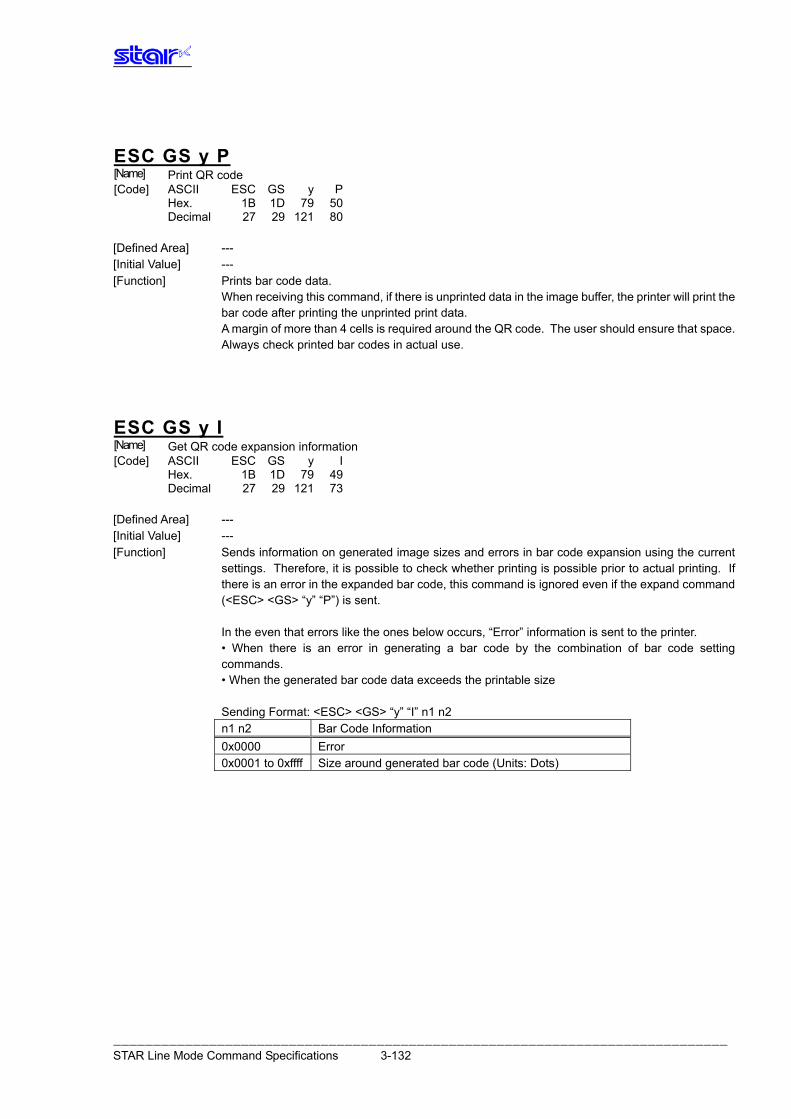
ESC GS y P [Name] Print QR code [Code] ASCII ESC GS y P Hex. 1B 1D 79 50 Decimal 27 29 121 80
[Defined Area] --- [Initial Value] --- [Function] Prints bar code data. When receiving this command, if there is unprinted data in the image buffer, the printer will print the
bar code after printing the unprinted print data. A margin of more than 4 cells is required around the QR code. The user should ensure that space. Always check printed bar codes in actual use.
ESC GS y I [Name] Get QR code expansion information [Code] ASCII ESC GS y I Hex. 1B 1D 79 49 Decimal 27 29 121 73
[Defined Area] --- [Initial Value] --- [Function] Sends information on generated image sizes and errors in bar code expansion using the current
settings. Therefore, it is possible to check whether printing is possible prior to actual printing. If there is an error in the expanded bar code, this command is ignored even if the expand command (<ESC> <GS> “y” “P”) is sent.
In the even that errors like the ones below occurs, “Error” information is sent to the printer. • When there is an error in generating a bar code by the combination of bar code setting
commands. • When the generated bar code data exceeds the printable size
Sending Format: <ESC> <GS> “y” “I” n1 n2 n1 n2 Bar Code Information 0x0000 Error 0x0001 to 0xffff Size around generated bar code (Units: Dots)
――――――――――――――――――――――――――――――――――――――――――――――――――――――――――――――――――――――――――――― STAR Line Mode Command Specifications 3-132
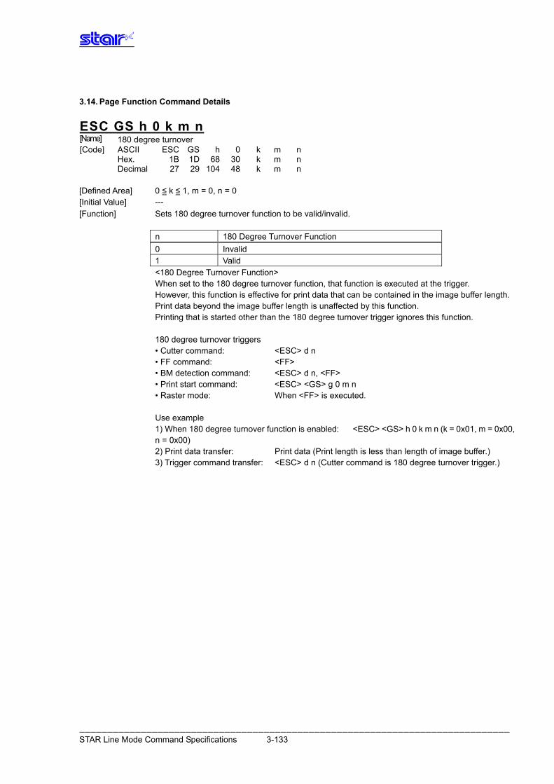
3.14. Page Function Command Details
ESC GS h 0 k m n [Name] 180 degree turnover [Code] ASCII ESC GS h 0 k m n Hex. 1B 1D 68 30 k m n Decimal 27 29 104 48 k m n
[Defined Area] 0 ≤ k ≤ 1, m = 0, n = 0 [Initial Value] --- [Function] Sets 180 degree turnover function to be valid/invalid.
n 180 Degree Turnover Function 0 Invalid 1 Valid
<180 Degree Turnover Function> When set to the 180 degree turnover function, that function is executed at the trigger. However, this function is effective for print data that can be contained in the image buffer length. Print data beyond the image buffer length is unaffected by this function. Printing that is started other than the 180 degree turnover trigger ignores this function. 180 degree turnover triggers • Cutter command: <ESC> d n • FF command: <FF> • BM detection command: <ESC> d n, <FF> • Print start command: <ESC> <GS> g 0 m n • Raster mode: When <FF> is executed. Use example 1) When 180 degree turnover function is enabled: <ESC> <GS> h 0 k m n (k = 0x01, m = 0x00,
n = 0x00) 2) Print data transfer: Print data (Print length is less than length of image buffer.) 3) Trigger command transfer: <ESC> d n (Cutter command is 180 degree turnover trigger.)
――――――――――――――――――――――――――――――――――――――――――――――――――――――――――――――――――――――――――――― STAR Line Mode Command Specifications 3-133
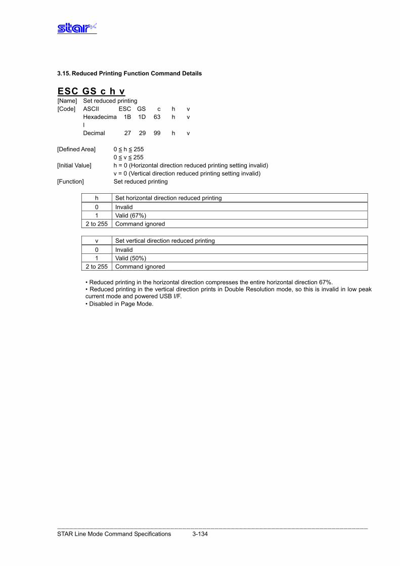
3.15. Reduced Printing Function Command Details
ESC GS c h v [Name] Set reduced printing [Code] ASCII ESC GS c h v Hexadecima
l 1B 1D 63 h v
Decimal 27 29 99 h v [Defined Area] 0 ≤ h ≤ 255 0 ≤ v ≤ 255 [Initial Value] h = 0 (Horizontal direction reduced printing setting invalid) v = 0 (Vertical direction reduced printing setting invalid) [Function] Set reduced printing
h Set horizontal direction reduced printing 0 Invalid 1 Valid (67%)
2 to 255 Command ignored
v Set vertical direction reduced printing 0 Invalid 1 Valid (50%)
2 to 255 Command ignored • Reduced printing in the horizontal direction compresses the entire horizontal direction 67%. • Reduced printing in the vertical direction prints in Double Resolution mode, so this is invalid in low peak
current mode and powered USB I/F. • Disabled in Page Mode.
――――――――――――――――――――――――――――――――――――――――――――――――――――――――――――――――――――――――――――― STAR Line Mode Command Specifications 3-134
3.16. Page Mode Command Details
ESC GS P 0 [Name] Selects page mode [Code] ASCII ESC GS P 0 Hexadecima
l 1B 1D 50 30
Decimal 27 29 80 48 [Function] Switches from standard mode to page mode. • Valid only when input at the top of the line.
• Invalid when input in page mode. • Returns to standard mode after running this command.
• ESC GS P 1 (selects standard mode) • ESC GS P 7 (prints in page mode and recovers)
• The character expansion position uses the starting point specified by ESC GS P2 (selection of character print direction in page mode) in the print region specified by ESC GS P 3 (set print region in page mode).
• Switches the following command setting values that have independent values for both page and standard modes to the setting values of page mode.
• Set space amount: ESC SP , ESC : , ESC M, ESC P, ESC g, ESC p, ESC s, ESC t • Set the line feed amount: ESC z, ESC 0, ESC 1, ESC 2, • Set horizontal tab: ESC D
• The following commands are invalid in page mode. • VT: Vertical tab • FF: Form feed • ESC GS c: Reduced Printing • ESC GS ) B: Text Search • ESC RS m: BM setting • ESC RS A: Printing Region Setting • ESC GS M: Maintenance counter control • ESC GS r: Get CRC • ESC GS %: User ID • ESC GS *: Print Mark • ESC RS C: Set printing mode • ESC * r: Related to raster mode • ESC RS r: Set print speed • ESC RS L: Lump print of logos • ESC FS p: Print logo
――――――――――――――――――――――――――――――――――――――――――――――――――――――――――――――――――――――――――――― STAR Line Mode Command Specifications 3-135
ESC GS P 1 [Name] Cancel page mode [Code] ASCII ESC GS P 1 Hexadecimal 1B 1D 50 31 Decimal 27 29 80 49 [Function] Cancels page mode. • Valid only when input in page mode.
• Data expanded in page mode is erased. • After execution, the top of the line is positioned at the next print starting position. • Print region set by ESC GS P 3 (Set print region in page mode) is initialized. • Switches the following command setting values that have independent values for both standard
and page modes to the setting values of standard mode.
• Set space amount: ESC SP , ESC: , ESC M, ESC P, ESC g, ESC p, ESC s, ESC t • Set the line feed amount: ESC z, ESC 0, ESC 1, ESC 2, • Set horizontal tab: ESC D
• The following commands are valid only when set in standard mode. • ESC GS P 3: Set print region in page mode • ESC GS P 2: Select character print direction in page mode
• The following commands are ignored in standard mode. • ESC GS P 4: Specify character vertical direction absolute position in
page mode • ESC GS P 5: Specify character vertical direction relative position in page mode • ESC GS P 6: Print data in page mode • ESC GS P 7: Print in page mode and recover • ESC GS P 8: Cancel print data in page mode • When power is turned on and when a reset is implemented, standard mode is selected when executing initialization (ESC @) of the printer.
ESC GS P 2 n [Name] Select character print direction in page mode [Code] ASCII ESC GS P 2 Hexadecimal 1B 1D 50 32 Decimal 27 29 80 50 [Defined Area] 0 ≤ n ≤ 3, 48 ≤ n ≤ 51 [Initial Value] n = 0 [Function] Select character print direction and starting point in page mode.
――――――――――――――――――――――――――――――――――――――――――――――――――――――――――――――――――――――――――――― STAR Line Mode Command Specifications 3-136
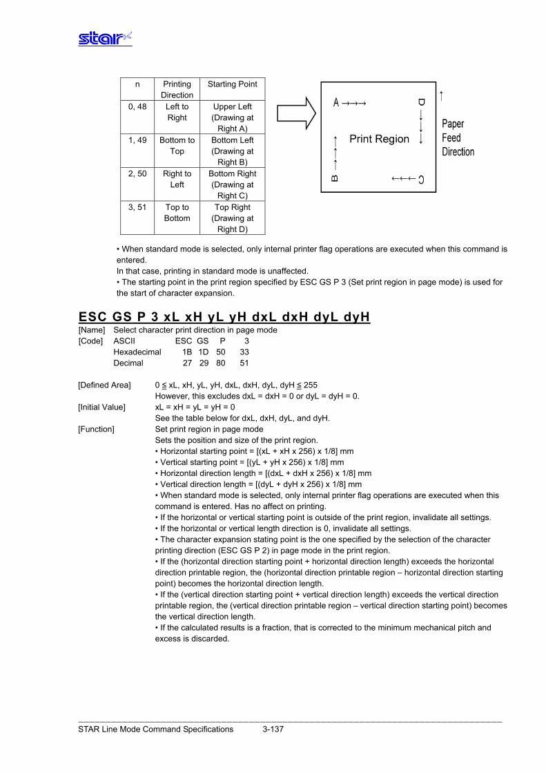
n Printing Direction
Starting Point 0, 48 Left to
Right Upper Left (Drawing at
Right A) 1, 49 Bottom to
Top Bottom Left (Drawing at
Right B) 2, 50 Right to
Left Bottom Right (Drawing at
Right C) 3, 51 Top to
Bottom Top Right
(Drawing at Right D)
• When standard mode is selected, only internal printer flag operations are executed when this command is entered. In that case, printing in standard mode is unaffected.
• The starting point in the print region specified by ESC GS P 3 (Set print region in page mode) is used for the start of character expansion.
ESC GS P 3 xL xH yL yH dxL dxH dyL dyH [Name] Select character print direction in page mode [Code] ASCII ESC GS P 3 Hexadecimal 1B 1D 50 33 Decimal 27 29 80 51 [Defined Area] 0 ≤ xL, xH, yL, yH, dxL, dxH, dyL, dyH ≤ 255
However, this excludes dxL = dxH = 0 or dyL = dyH = 0. [Initial Value] xL = xH = yL = yH = 0
See the table below for dxL, dxH, dyL, and dyH. [Function] Set print region in page mode
Sets the position and size of the print region. • Horizontal starting point = [(xL + xH x 256) x 1/8] mm • Vertical starting point = [(yL + yH x 256) x 1/8] mm • Horizontal direction length = [(dxL + dxH x 256) x 1/8] mm • Vertical direction length = [(dyL + dyH x 256) x 1/8] mm
• When standard mode is selected, only internal printer flag operations are executed when this command is entered. Has no affect on printing.
• If the horizontal or vertical starting point is outside of the print region, invalidate all settings. • If the horizontal or vertical length direction is 0, invalidate all settings. • The character expansion stating point is the one specified by the selection of the character
printing direction (ESC GS P 2) in page mode in the print region. • If the (horizontal direction starting point + horizontal direction length) exceeds the horizontal
direction printable region, the (horizontal direction printable region – horizontal direction starting point) becomes the horizontal direction length.
• If the (vertical direction starting point + vertical direction length) exceeds the vertical direction printable region, the (vertical direction printable region – vertical direction starting point) becomes the vertical direction length.
• If the calculated results is a fraction, that is corrected to the minimum mechanical pitch and excess is discarded.
――――――――――――――――――――――――――――――――――――――――――――――――――――――――――――――――――――――――――――― STAR Line Mode Command Specifications 3-137
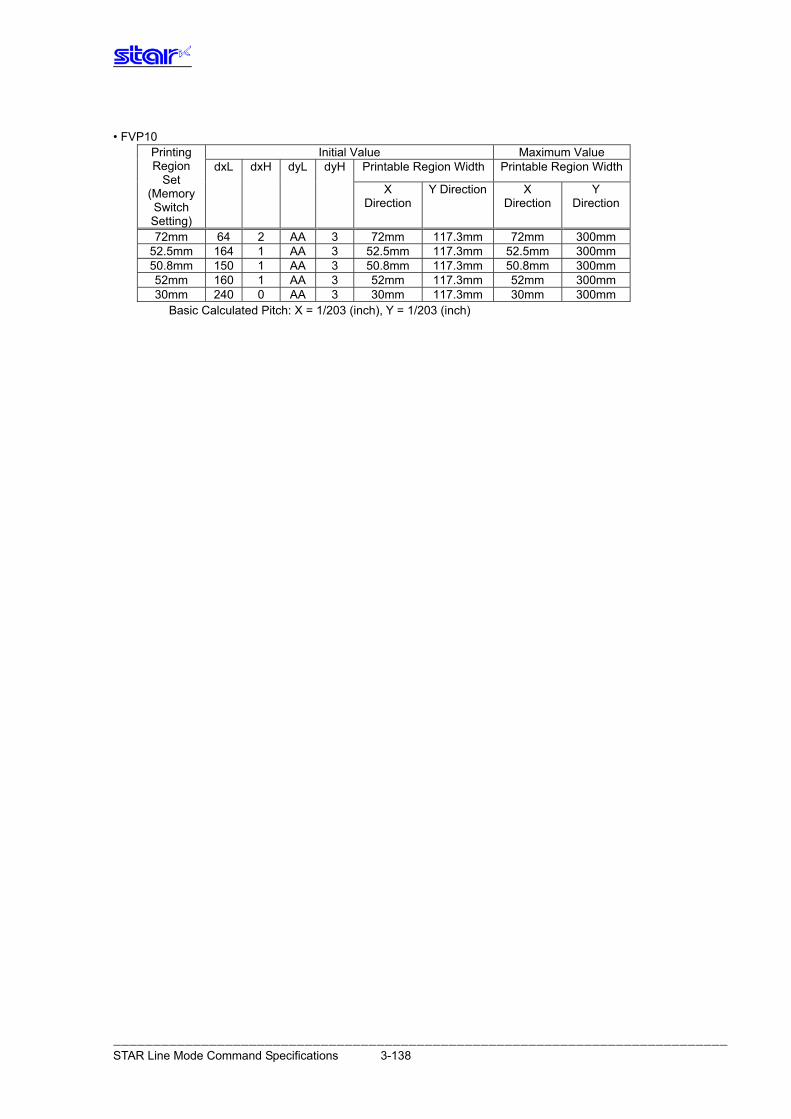
• FVP10
Initial Value Maximum Value Printable Region Width Printable Region Width
Printing Region dxL dxH dyL dyH
Set X
Direction Y Direction X
Direction Y
Direction (Memory Switch Setting) 72mm 64 2 AA 3 72mm 117.3mm 72mm 300mm
52.5mm 164 1 AA 3 52.5mm 117.3mm 52.5mm 300mm 50.8mm 150 1 AA 3 50.8mm 117.3mm 50.8mm 300mm 52mm 160 1 AA 3 52mm 117.3mm 52mm 300mm 30mm 240 0 AA 3 30mm 117.3mm 30mm 300mm
Basic Calculated Pitch: X = 1/203 (inch), Y = 1/203 (inch)
――――――――――――――――――――――――――――――――――――――――――――――――――――――――――――――――――――――――――――― STAR Line Mode Command Specifications 3-138
ESC GS P 4 nL nH [Name] Specify character vertical direction absolute position in page mode [Code] ASCII ESC GS P 4 Hexadecima
l 1B 1D 50 34
Decimal 27 29 80 52 [Defined Area] 0 ≤ nL ≤ 255, 0 ≤ nH ≤ 255 [Initial Value] - - - [Function] Specify the position for character vertical direction of the data expansion starting position in page
mode with the absolute position that uses the starting point as a reference. The position of the character vertical direction of the starting position for subsequent data expansion uses the position from the starting point [(nL + nH x 256) x 1/8]mm.
• This command is ignored when page mode is not selected. • Absolute position specifications that exceed the specified print region are ignored. • The position of the character horizontal direction of the data expansion starting position does not
move. • Specify the reference starting point using ESC GS P 2. • The following operations will occur depending on the starting point of ESC GS P 2
(select character print direction in page mode). a. When the starting point is “upper left” or “bottom right,” specify the absolute position of the paper feed
direction. b. When the starting point is “upper right” or “bottom left,” specify the absolute position of the
perpendicular direction to the paper feed. • If the calculated results is a fraction, that is corrected to the minimum mechanical pitch and
excess is discarded.
――――――――――――――――――――――――――――――――――――――――――――――――――――――――――――――――――――――――――――― STAR Line Mode Command Specifications 3-139
ESC GS P 5 nL nH [Name] Specify character vertical direction relative position in page mode [Code] ASCII ESC GS P 5 Hexadecima
l 1B 1D 50 35
Decimal 27 29 80 53 [Defined Area] 0 ≤ nL ≤ 255, 0 ≤ nH ≤ 255 [Initial Value] - - - [Function] Specify the position for character vertical direction of the data expansion starting position in page
mode with the relative position that uses the current position as a reference. The subsequent data expansion starting position uses the position moved [(nL + nH x 256) x 1/8] mm from the current position.
• This command is ignored when page mode is not selected. • When specifying the characters downward from the current position the value is positive (plus);
when specifying upward, the value is negative (minus). • Negative numbers are represented by a complement of 65536. For example, use the following to
move upward N pitches. nL + nH x 256 = 65536-N
• Relative position specifications that exceed the specified print region are ignored. • The following operations will occur depending on the ESC GS P 2 (select character print
direction in page mode). a. When the starting point is “upper left” or “bottom right,” specify the absolute position of the
paper feed direction. b. When the starting point is “upper right” or “bottom left,” specify the relative position of the
perpendicular direction to the paper feed. • If the calculated results is a fraction, that is corrected to the minimum mechanical pitch and
excess is discarded.
――――――――――――――――――――――――――――――――――――――――――――――――――――――――――――――――――――――――――――― STAR Line Mode Command Specifications 3-140
ESC GS P 6 [Name] Print data in page mode [Code] ASCII ESC GS P 6 Hexadecimal 1B 1D 50 36 Decimal 27 29 80 54 [Function] Lump-prints data expanded to the entire print region in page mode. • Valid only when page mode is selected.
• After printing, the following information is maintained. a. Expanded data
b. Selection of character print direction in page mode (ESC GS P 2) c. Setting of print region in page mode (ESC GS P 3) d. Character expansion position
ESC GS P 7 [Name] Print in page mode and recover [Code] ASCII ESC GS P 7 Hexadecima
l 1B 1D 50 37
Decimal 27 29 80 55 [Function] Lump-prints data expanded to the entire print region and recovers to standard mode. • All expanded data is erased after printing.
• Print region set by ESC GS P 3 (Set print region in page mode) is initialized. • No paper cut is executed. • After execution, the top of the line is positioned at the next print starting position. • Valid only when page mode is selected.
ESC GS P 8 [Name] Cancel print data in page mode [Code] ASCII ESC GS P 8 Hexadecimal 1B 1D 50 38 Decimal 27 29 80 56 [Function] Erases all data in presently set print region, in page mode. • Valid only when page mode is selected.
• Portion included in the currently set print region is deleted even if data of the print region set previously.
――――――――――――――――――――――――――――――――――――――――――――――――――――――――――――――――――――――――――――― STAR Line Mode Command Specifications 3-141
3.17. Text Search Command Details
ESC GS ) B pL pH fn [parameter] [Name] Set text search [Code] ASCII ESC ) B pL pH fn [parameter] Hexadecimal 1B 29 42 pL pH fn [parameter] Decimal 27 41 66 pL pH fn [parameter] [Function] Runs processes related to text search.
• pL and pH specify the parameter count (pL + pH x 256) in bytes after fn. • See the function specifications for details on [parameter].
fn Function No. Function Name 48 Function 48 Enable and disables text search 49 Function 49 Set the number of times to run the text search macro 50 Function 50 Set to print the string that matches in the text search 64 Function 64 Define the text search string 65 Function 65 Define the text search macro 80 Function 80 Register text search settings and definitions in the non-volatile memory 81 Function 81 Initialize text search settings and definitions 96 Function 96 Print the text search settings and definitions 97 Function 97 Run the text search macro
<Function 48> ESC GS ) B pL pH fn m (fn = 48) [Name] Enable and disables text search [Code] ASCII ESC GS ) B pL pH fn m Hexadecimal 1B 1D 29 42 pL pH fn m Decimal 27 29 41 66 pL pH fn m [Defined Area] pL = 2, pH = 0
fn = 48 m = 0, 1
[Initial Value] Depends on setting registered in the non-volatile memory (At the time of shipment: m = 0) [Function] Makes text searches valid or invalid.
m Set 0 Invalid 1 Valid
When text search is valid, determines whether a string registered in the printer in advance is in the print data. If it is included, run a text search macro that corresponds to that string after running the following trigger command. • Execute cuts by continous <LF>. • <ESC> “d” No setting when the parameter is not a valid value. This setting is applied to printer operations when this command is processed. This setting is registered to non-volatile memory by the ESC GS ) B <Function 80) command. This command is ignored when the text search macro is running. Disabled in Page Mode.
――――――――――――――――――――――――――――――――――――――――――――――――――――――――――――――――――――――――――――― STAR Line Mode Command Specifications 3-142
<Function 49> ESC GS ) B pL pH fn m (fn = 49) [Name] Set the number of times to run the text search macro [Code] ASCII ESC GS ) B pL pH fn m Hexadecimal 1B 1D 29 42 pL pH fn m Decimal 27 29 41 66 pL pH fn m [Defined Area] pL = 2, pH = 0 fn = 49 m = 0, 1 [Initial Value] Depends on setting registered in the non-volatile memory (At the time of shipment: m = 0) [Function] Sets the number of times to run the text search macro when the strings match.
m Set 0 Run one time 1 Run for the number of times strings match
No setting when the parameter is not a valid value. This setting is applied to printer operations when this command is processed. This setting is registered to non-volatile memory by the ESC GS ) B <Function 80) command. This command is ignored when the text search macro is running. Disabled in Page Mode.
<Function 50> ESC GS ) B pL pH fn m (fn = 50) [Name] Set to print the string that matches in the text search [Code] ASCII ESC GS ) B pL pH fn m Hexadecimal 1B 1D 29 42 pL pH fn m Decimal 27 29 41 66 pL pH fn m [Defined Area] pL = 2, pH = 0 fn = 50 m = 0, 1, 2 [Initial Value] Depends on setting registered in the non-volatile memory (At the time of shipment: m = 0) [Function] Sets the string print operation when strings match.
m Set 0 Prints the string 1 Does not print the string 2 Switches the string with a blank character
No setting when the parameter is not a valid value. This setting is applied to printer operations when this command is processed. This setting is registered to non-volatile memory by the ESC GS ) B <Function 80) command. This command is ignored when the text search macro is running. Disabled in Page Mode.
――――――――――――――――――――――――――――――――――――――――――――――――――――――――――――――――――――――――――――― STAR Line Mode Command Specifications 3-143
<Function 64> ESC GS ) B pL pH fn m k d1…dk (fn = 64) [Name] Define the text search string [Code] ASCII ESC GS ) B pL pH fn n m k d1 ... dk Hexadecimal 1B 1D 29 42 pL pH fn n m k d1 ... dk Decimal 27 29 41 66 pL pH fn n m k d1 ... dk [Defined Area] 4 ≤ (pL + pH x 256) ≤ 65535 (0 ≤ pL ≤ 255, 0 ≤ pH ≤ 255)
fn = 64 1 ≤ n ≤ 100 1 ≤ m ≤ 100 0 ≤ k ≤ 32 32 ≤ d ≤ 255
[Initial Value] Depends on setting registered in the non-volatile memory (At the time of shipment: no string definition)
[Function] Defines the text search string for number n. If the text search string for number n is already defined, it is overwritten. M specifies the text search macro number to run. K specifies the size of the defined data in bytes. D specifies the defined data. When the parameter has an invalid value, no definition. This definition is applied to printer operations when this command is processed. This definition is registered to non-volatile memory by the ESC GS ) B <Function 80) command. This command is ignored when the text search macro is running. Disabled in Page Mode.
<Function 65> ESC GS ) B pL pH fn m k1 k2 d1…dk (fn = 65) [Name] Define the text search macro [Code] ASCII ESC GS ) B pL pH fn m k1 k2 d1 ... dk Hexadecimal 1B 1D 29 42 pL pH fn m k1 k2 d1 ... dk Decimal 27 29 41 66 pL pH fn m k1 k2 d1 ... dk [Defined Area] 4 ≤ (pL + pH x 256) ≤ 65535 (0 ≤ pL ≤ 255, 0 ≤ pH ≤ 255)
fn = 65 1 ≤ m ≤ 100 0 ≤ (k = k1 + k2 x 256) ≤ 7680 (0 ≤ k1 ≤ 255, 0 ≤ k2 ≤ 30) (Size of defined area = 7,680 bytes) 0 ≤ d ≤ 255
[Initial Value] Depends on setting registered in the non-volatile memory (At the time of shipment: no text search macro definition)
[Function] Defines the text search macro for number m. If the text search macro for number m is already defined, it is overwritten. (k = k1 + k2 x 256) specifies the size of the defined data in bytes. d specifies the defined data. If the parameter has an invalid value, processing of this command ends at that point. This definition is applied to printer operations when this command is processed. This definition is registered to non-volatile memory by the ESC GS ) B <Function 80) command. This command is ignored when the text search macro is running. Disabled in Page Mode.
――――――――――――――――――――――――――――――――――――――――――――――――――――――――――――――――――――――――――――― STAR Line Mode Command Specifications 3-144
<Function 80> ESC GS ) B pL pH fn m (fn = 80) [Name] Register text search settings and definitions in the non-volatile memory [Code] ASCII ESC GS ) B pL pH fn m Hexadecimal 1B 1D 29 42 pL pH fn m Decimal 27 29 41 66 pL pH fn m [Defined Area] pL = 2, pH = 0 fn = 80 m = 0 [Initial Value] --- [Function] Registers the text search setting to non-volatile memory.
The following shows the contents to register. Function No. Contents Function 48 Enable and disables text search Function 49 Set the number of times to run the text search macro Function 50 Set to print the string that matches in the text search Function 64 Define the text search string Function 65 Define the text search macro Function 81 Initialize text search settings and definitions
After registration ends, resets the printer. The printer operates by reading the setting registered using this command the next time the printer power is turned on. This command is ignored when the text search macro is running. Consider the life of the non-volatile memory and avoid over-sue of this command. Disabled in Page Mode.
<Function 81> ESC GS ) B pL pH fn m (fn = 81) [Name] Initialize text search settings and definitions [Code] ASCII ESC GS ) B pL pH fn m Hexadecimal 1B 1D 29 42 pL pH fn m Decimal 27 29 41 66 pL pH fn m [Defined Area] pL = 2, pH = 0
fn = 81 m = 0
[Initial Value] --- [Function] Initialize text search settings and definitions The following shows the contents to initialize.
Function No. Contents Initial Value Function 48 Enable and disables text search Invalid Function 49 Set the number of times to run the text search macro 1 times Function 50 Set to print the string that matches in the text search Prints the string Function 64 Define the text search string No text search string definition Function 65 Define the text search macro No text search macro definition
This setting is applied to printer operations when this command is processed. This setting is registered to non-volatile memory by the ESC GS ) B <Function 80) command. This command is ignored when the text search macro is running. Disabled in Page Mode.
――――――――――――――――――――――――――――――――――――――――――――――――――――――――――――――――――――――――――――― STAR Line Mode Command Specifications 3-145
<Function 96> ESC GS ) B pL pH fn m (fn = 96) [Name] Print the text search settings and definitions [Code] ASCII ESC GS ) B pL pH fn m Hexadecimal 1B 1D 29 42 pL pH fn m Decimal 27 29 41 66 pL pH fn m [Defined Area] pL = 2, pH = 0
fn = 96 m = 0
[Initial Value] --- [Function] Prints text search settings and definitions
The following shows the contents to print. Function No. Contents Function 48 Enable and disables text search Function 49 Set the number of times to run the text search macro Function 50 Set to print the string that matches in the text search Function 64 Define the text search string Function 65 Define the text search macro
The text search macro is not run at this time. This command is ignored when the text search macro is running. Disabled in Page Mode.
<Function 97> ESC GS ) B pL pH fn m (fn = 97) [Name] Run the text search macro [Code] ASCII ESC GS ) B pL pH fn m Hexadecimal 1B 1D 29 42 pL pH fn m Decimal 27 29 41 66 pL pH fn m [Defined Area] pL = 2, pH = 0
fn = 97 1 ≤ m ≤ 100
[Initial Value] --- [Function] Runs the text search macro for number m.
This command is ignored when the text search macro is running. Disabled in Page Mode.
――――――――――――――――――――――――――――――――――――――――――――――――――――――――――――――――――――――――――――― STAR Line Mode Command Specifications 3-146
3.18. Audio Command Details
ESC GS s O z a n c1 c2 d1 d2 t1 t2 [Name] Playback NV audio [Code] ASCII ESC GS s O z a n c1 c2 d1 d2 t1 t2 Hexadecimal 1B 1D 73 4F z a n c1 c2 d1 d2 t1 t2 Decimal 27 29 115 79 z a n c1 c2 d1 d2 t1 t2 [Defined Area] Z = 0
a = 0, 1, 48, 49 1 ≤ n ≤ 255 1 ≤ c1 + c2x256 ≤ 65535 0 ≤ d1 + d2x256 ≤ 65535 0 ≤ t1 + t2x256 ≤ 65535
[Initial Value] --- [Function] Plays back the specified NV audio. a specifies the area where the audio data to playback is stored.
a Audio data storage area 1, 49 User area
n specifies the audio number to playback. (c1 + c2 x 256) specifies the number of times. (d1 + d2 x 256) specifies the delay time. Delay time is the time from starting to process this command to the start of audio playback
(in seconds). (t1 + t2 x 256) specifies the interval time. Interval time is the time from the end of the previous audio to the start of the next audio
(in seconds). If audio is already being played back, playback after waiting for the end of the audio. If the printer is printing, playback after printing is ended. When the parameter has an invalid value, there is no audio playback. If the audio data of the specified audio number has not been registered, there will be no playback. Audio will stop by inputting the FEED switch while there is audio playback using this command. Audio will stop using the NV audio stop command (ESC GS s P) while there is audio playback using this command.
――――――――――――――――――――――――――――――――――――――――――――――――――――――――――――――――――――――――――――― STAR Line Mode Command Specifications 3-147
ESC GS s P [Name] Stop NV audio [Code] ASCII ESC GS s P Hexadecimal 1B 1D 73 50 Decimal 27 29 115 80 [Defined Area] --- [Initial Value] --- [Function] Stops audio playback for the following reasons.
NV audio playback command ESC GS s O NV audio lump playback command ESC GS s T When run in real-time when this command is received This command is ignored with there is no audio playback.
ESC GS s R z n1 n2 n3 d1 … dn [Name] Playback received audio [Code] ASCII ESC GS s R z n1 n2 n3 d1 … dn Hexadecimal 1B 1D 73 52 z n1 n2 n3 d1 … dn Decimal 27 29 115 82 z n1 n2 n3 d1 … dn [Defined Area] Z = 0 1 ≤ (n = n1 + n2 x 256 + n3 * 65536) ≤ 16777215 0 ≤ d ≤ 255 [Initial Value] --- [Function] Does not register audio data in the non-volatile memory and plays back one time while receiving
data. (n1 + n2 x 256 + n3 x 65536) specifies the number of bytes of the audio data. d is audio data in sampling frequency of 11.025 kHz, ADPCM format in quantization bit rate of 4 bits. When data transfer from the host is slow (theoretical value: 44,100 bps or lower), playback is intermittent.
――――――――――――――――――――――――――――――――――――――――――――――――――――――――――――――――――――――――――――― STAR Line Mode Command Specifications 3-148
ESC GS s I z e a n c1 c2 d1 d2 t1 t2 … 0xFF [Name] Register automatic audio setting information [Code] ASCII ESC GS s I z e a n c1 c2 d1 d2 t1 t2 … 0xFF Hexadecimal 1B 1D 73 49 z e a n c1 c2 d1 d2 t1 t2 … FF Decimal 27 29 115 73 z e a n c1 c2 d1 d2 t1 t2 … 255 [Defined Area] z = 0, 1
0 ≤ e ≤ 63(0x3F) a = 1, 49 0 ≤ n ≤ 255 0 ≤ c1 + c2 x 256 ≤ 65535 0 ≤ d1 + d2 x 256 ≤ 65535 0 ≤ t1 + t2 x 256 ≤ 65535
[Initial Value] At the time of shipment: Set to automatic audio
e Printer Internal Status a n c1 + c2x256 d1 + d2x256 t1 + t2x256 0x00 Cutter error 0 1 1 0 0 0x01 Flash ROM error 0 2 1 0 0 0x02 EE-PROM error 0 3 1 0 0 0x03 SRAM error 0 4 1 0 0 0x04 Head temperature
detection error 0 5 1 0 0
0x05 Power voltage error 0 6 1 0 0 0x06 to 0x0F (Reserved) 0 0 0 0 0
0x10 BM Error 0 7 1 0 0 0x11 PE error 0 8 1 0 0 0x12 Cover open 0 9 1 5 0 0x13 NE error 0 10 1 0 0
0x14 to 0x1F (Reserved) 0 0 0 0 0 0x20 Head high
temperature stop error 0 11 1 0 0
0x21 to 0x2F (Reserved) 0 0 0 0 0 0x30 Idling 0 0 0 0 0
0x31 to 0x3F (Reserved) 0 0 0 0 0 [Function] When z = 1, the automatic audio setting information returns to the default factory setting. (At this
time, do not send parameters after e.) When z = 0, register the automatic audio setting information to playback when the printer’s internal status occurs. e specifies the printer’s internal status assigned to audio. a specifies the area where the audio data to set is stored.
a Audio data storage area 1, 49 User area
n specifies the audio number to playback. However, when n = 0, or audio data of a specified number is not registered, automatic audio is invalid. (c1 + c2 x 256) specifies the number of times. (d1 + d2 x 256) specifies the delay time. Delay time is the time from the occurrence of the printer’s internal status to the start of audio
playback (in seconds). (t1 + t2 x 256) specifies the interval time. Interval time is the time from the end of the previous audio to the start of the next audio (in
seconds). You can register multiple times by repeating parameters e to t2.
――――――――――――――――――――――――――――――――――――――――――――――――――――――――――――――――――――――――――――― STAR Line Mode Command Specifications 3-149
Perform lump registration until 0xFF which is the end code. When the parameter is determined to be free of error, the printer starts processing this command. When the parameter has an invalid value, there is no setting. (Sets already determined to be free of problems are valid.) This command should be specified at the top of the line. After registering automatic audio setting information, reset the printer. Error processing mechanical operations or status processing and the like are not possible while registering automatic audio setting information (the time from receiving 0xFF which is the end code until printer reset is completed after automatic audio registration ends). Audio will stop by inputting the FEED switch while there is audio playback using this setting. Command Transmission Example Cutter error: User area 12th/3 times/delay 2 seconds/interval 1 second, Flash ROM error: User area 13th/4 times/delay 5 seconds/interval 6 seconds ESC GS s I z e a n c1 c2 d1 d2 t1 t2 1B 1D 73 49 00 00 01 0C 03 00 02 00 01 00 01 01 0D 04 00 05 00 06 00 FF
――――――――――――――――――――――――――――――――――――――――――――――――――――――――――――――――――――――――――――― STAR Line Mode Command Specifications 3-150
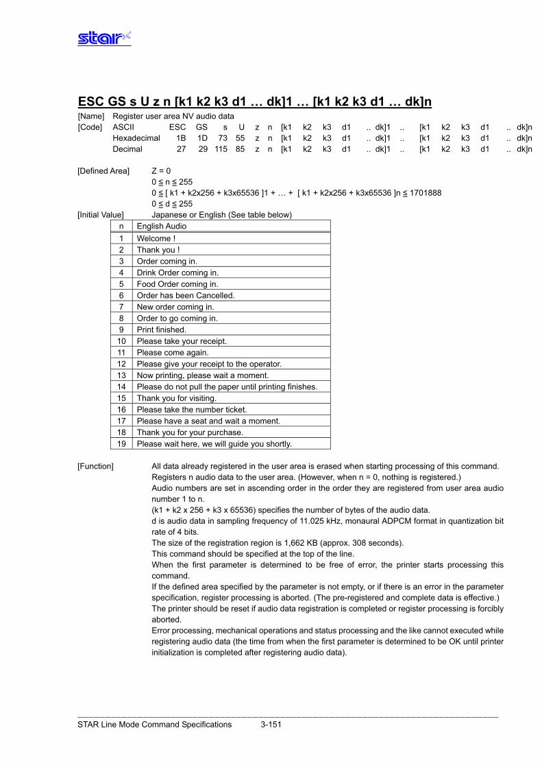
ESC GS s U z n [k1 k2 k3 d1 … dk]1 … [k1 k2 k3 d1 … dk]n [Name] Register user area NV audio data [Code] ASCII ESC GS s U z n [k1 k2 k3 d1 .. dk]1 .. [k1 k2 k3 d1 .. dk]n Hexadecimal 1B 1D 73 55 z n [k1 k2 k3 d1 .. dk]1 .. [k1 k2 k3 d1 .. dk]n Decimal 27 29 115 85 z n [k1 k2 k3 d1 .. dk]1 .. [k1 k2 k3 d1 .. dk]n [Defined Area] Z = 0
0 ≤ n ≤ 255 0 ≤ [ k1 + k2x256 + k3x65536 ]1 + … + [ k1 + k2x256 + k3x65536 ]n ≤ 1701888 0 ≤ d ≤ 255
[Initial Value] Japanese or English (See table below) n English Audio 1 Welcome ! 2 Thank you ! 3 Order coming in. 4 Drink Order coming in. 5 Food Order coming in. 6 Order has been Cancelled. 7 New order coming in. 8 Order to go coming in. 9 Print finished.
10 Please take your receipt. 11 Please come again. 12 Please give your receipt to the operator. 13 Now printing, please wait a moment. 14 Please do not pull the paper until printing finishes. 15 Thank you for visiting. 16 Please take the number ticket. 17 Please have a seat and wait a moment. 18 Thank you for your purchase. 19 Please wait here, we will guide you shortly.
[Function] All data already registered in the user area is erased when starting processing of this command. Registers n audio data to the user area. (However, when n = 0, nothing is registered.) Audio numbers are set in ascending order in the order they are registered from user area audio number 1 to n. (k1 + k2 x 256 + k3 x 65536) specifies the number of bytes of the audio data. d is audio data in sampling frequency of 11.025 kHz, monaural ADPCM format in quantization bit rate of 4 bits. The size of the registration region is 1,662 KB (approx. 308 seconds). This command should be specified at the top of the line. When the first parameter is determined to be free of error, the printer starts processing this command. If the defined area specified by the parameter is not empty, or if there is an error in the parameter specification, register processing is aborted. (The pre-registered and complete data is effective.) The printer should be reset if audio data registration is completed or register processing is forcibly aborted. Error processing, mechanical operations and status processing and the like cannot executed while registering audio data (the time from when the first parameter is determined to be OK until printer initialization is completed after registering audio data).
――――――――――――――――――――――――――――――――――――――――――――――――――――――――――――――――――――――――――――― STAR Line Mode Command Specifications 3-151
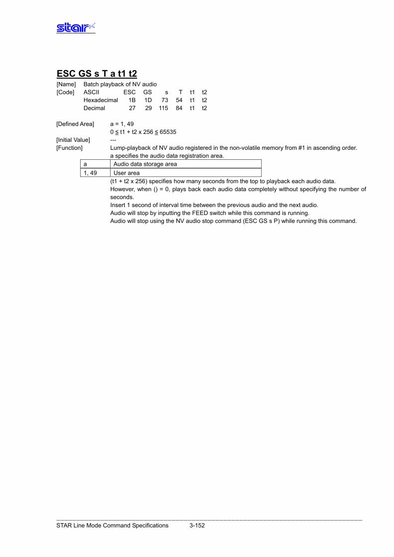
ESC GS s T a t1 t2 [Name] Batch playback of NV audio [Code] ASCII ESC GS s T t1 t2 Hexadecimal 1B 1D 73 54 t1 t2 Decimal 27 29 115 84 t1 t2 [Defined Area] a = 1, 49 0 ≤ t1 + t2 x 256 ≤ 65535 [Initial Value] --- [Function] Lump-playback of NV audio registered in the non-volatile memory from #1 in ascending order. a specifies the audio data registration area.
a Audio data storage area 1, 49 User area
(t1 + t2 x 256) specifies how many seconds from the top to playback each audio data. However, when () = 0, plays back each audio data completely without specifying the number of
seconds. Insert 1 second of interval time between the previous audio and the next audio. Audio will stop by inputting the FEED switch while this command is running. Audio will stop using the NV audio stop command (ESC GS s P) while running this command.
――――――――――――――――――――――――――――――――――――――――――――――――――――――――――――――――――――――――――――― STAR Line Mode Command Specifications 3-152
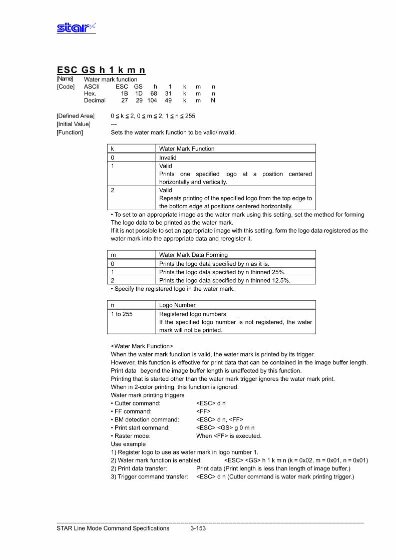
ESC GS h 1 k m n [Name] Water mark function [Code] ASCII ESC GS h 1 k m n Hex. 1B 1D 68 31 k m n Decimal 27 29 104 49 k m N
[Defined Area] 0 ≤ k ≤ 2, 0 ≤ m ≤ 2, 1 ≤ n ≤ 255 [Initial Value] --- [Function] Sets the water mark function to be valid/invalid.
k Water Mark Function 0 Invalid 1 Valid
Prints one specified logo at a position centered horizontally and vertically.
2 Valid Repeats printing of the specified logo from the top edge to the bottom edge at positions centered horizontally.
• To set to an appropriate image as the water mark using this setting, set the method for forming The logo data to be printed as the water mark. If it is not possible to set an appropriate image with this setting, form the logo data registered as the water mark into the appropriate data and reregister it.
m Water Mark Data Forming 0 Prints the logo data specified by n as it is. 1 Prints the logo data specified by n thinned 25%. 2 Prints the logo data specified by n thinned 12.5%.
• Specify the registered logo in the water mark.
n Logo Number 1 to 255 Registered logo numbers.
If the specified logo number is not registered, the water mark will not be printed.
<Water Mark Function> When the water mark function is valid, the water mark is printed by its trigger. However, this function is effective for print data that can be contained in the image buffer length. Print data beyond the image buffer length is unaffected by this function. Printing that is started other than the water mark trigger ignores the water mark print. When in 2-color printing, this function is ignored. Water mark printing triggers • Cutter command: <ESC> d n • FF command: <FF> • BM detection command: <ESC> d n, <FF> • Print start command: <ESC> <GS> g 0 m n • Raster mode: When <FF> is executed. Use example 1) Register logo to use as water mark in logo number 1. 2) Water mark function is enabled: <ESC> <GS> h 1 k m n (k = 0x02, m = 0x01, n = 0x01) 2) Print data transfer: Print data (Print length is less than length of image buffer.) 3) Trigger command transfer: <ESC> d n (Cutter command is water mark printing trigger.)
――――――――――――――――――――――――――――――――――――――――――――――――――――――――――――――――――――――――――――― STAR Line Mode Command Specifications 3-153
4. CHARACT ER CODE TABLES
Refer to the separate ”Character Code Tables” .
――――――――――――――――――――――――――――――――――――――――――――――――――――――――――――――――――――――――――――― STAR Line Mode Command Specifications 4-1
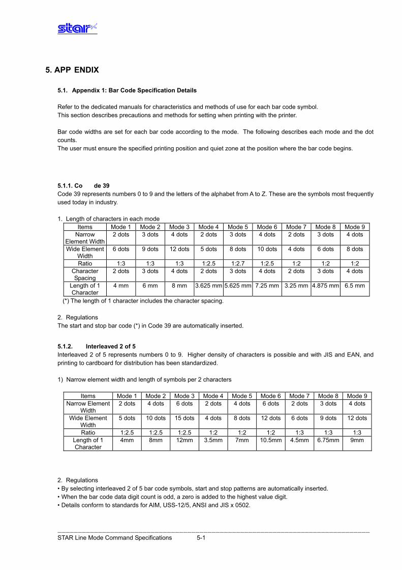
5. APP ENDIX
5.1. Appendix 1: Bar Code Specification Details Refer to the dedicated manuals for characteristics and methods of use for each bar code symbol. This section describes precautions and methods for setting when printing with the printer. Bar code widths are set for each bar code according to the mode. The following describes each mode and the dot counts. The user must ensure the specified printing position and quiet zone at the position where the bar code begins.
5.1.1. Co de 39 Code 39 represents numbers 0 to 9 and the letters of the alphabet from A to Z. These are the symbols most frequently used today in industry. 1. Length of characters in each mode
Items Mode 1 Mode 2 Mode 3 Mode 4 Mode 5 Mode 6 Mode 7 Mode 8 Mode 9Narrow
Element Width 2 dots 3 dots 4 dots 2 dots 3 dots 4 dots 2 dots 3 dots 4 dots
Wide Element Width
6 dots 9 dots 12 dots 5 dots 8 dots 10 dots 4 dots 6 dots 8 dots
Ratio 1:3 1:3 1:3 1:2.5 1:2.7 1:2.5 1:2 1:2 1:2 Character Spacing
2 dots 3 dots 4 dots 2 dots 3 dots 4 dots 2 dots 3 dots 4 dots
Length of 1 Character
4 mm 6 mm 8 mm 3.625 mm 5.625 mm 7.25 mm 3.25 mm 4.875 mm 6.5 mm
(*) The length of 1 character includes the character spacing. 2. Regulations The start and stop bar code (*) in Code 39 are automatically inserted.
5.1.2. Interleaved 2 of 5 Interleaved 2 of 5 represents numbers 0 to 9. Higher density of characters is possible and with JIS and EAN, and printing to cardboard for distribution has been standardized. 1) Narrow element width and length of symbols per 2 characters
Items Mode 1 Mode 2 Mode 3 Mode 4 Mode 5 Mode 6 Mode 7 Mode 8 Mode 9Narrow Element
Width 2 dots 4 dots 6 dots 2 dots 4 dots 6 dots 2 dots 3 dots 4 dots
Wide Element Width
5 dots 10 dots 15 dots 4 dots 8 dots 12 dots 6 dots 9 dots 12 dots
Ratio 1:2.5 1:2.5 1:2.5 1:2 1:2 1:2 1:3 1:3 1:3 Length of 1 Character
4mm 8mm 12mm 3.5mm 7mm 10.5mm 4.5mm 6.75mm 9mm
2. Regulations • By selecting interleaved 2 of 5 bar code symbols, start and stop patterns are automatically inserted. • When the bar code data digit count is odd, a zero is added to the highest value digit. • Details conform to standards for AIM, USS-12/5, ANSI and JIS x 0502.
――――――――――――――――――――――――――――――――――――――――――――――――――――――――――――――――――――――――――――― STAR Line Mode Command Specifications 5-1
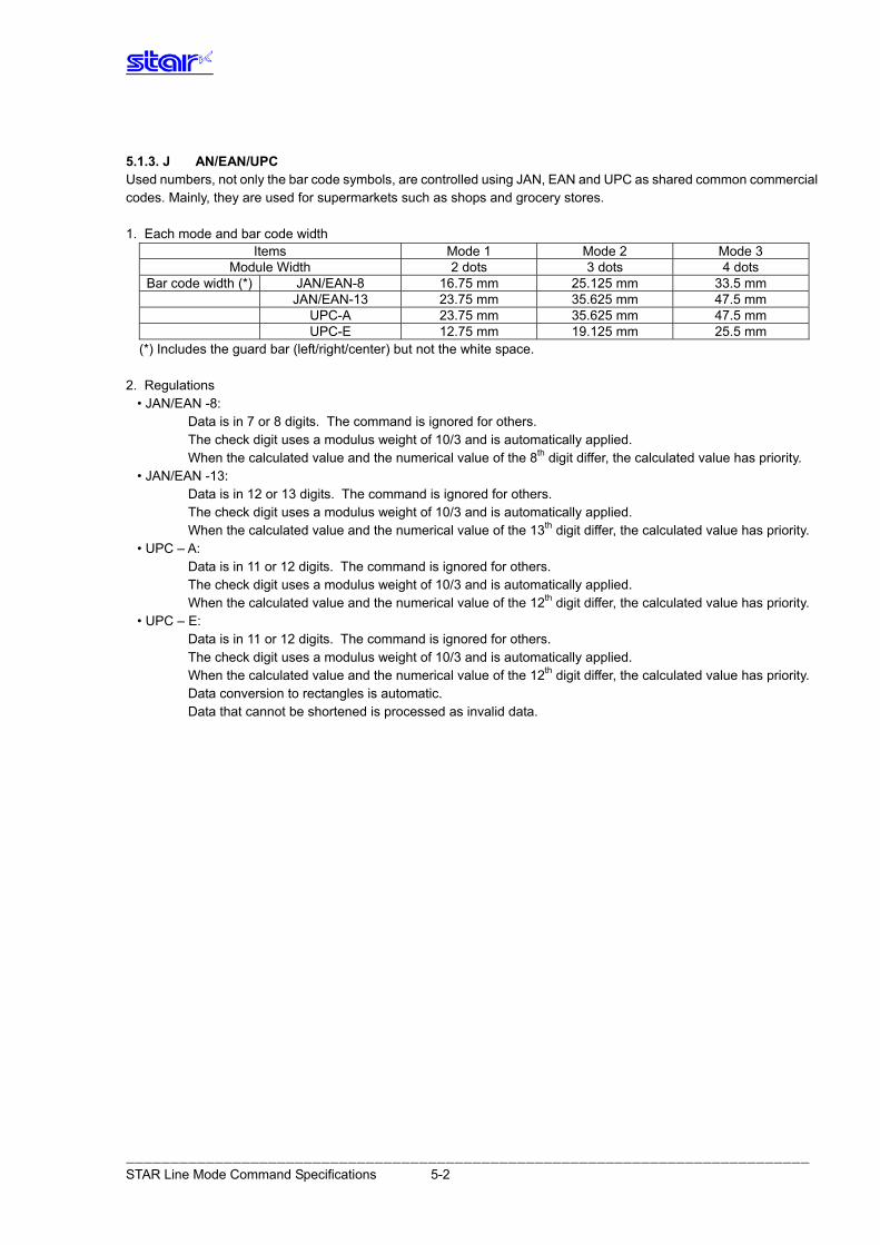
5.1.3. J AN/EAN/UPC Used numbers, not only the bar code symbols, are controlled using JAN, EAN and UPC as shared common commercial codes. Mainly, they are used for supermarkets such as shops and grocery stores. 1. Each mode and bar code width
Items Mode 1 Mode 2 Mode 3 Module Width 2 dots 3 dots 4 dots
Bar code width (*) JAN/EAN-8 16.75 mm 25.125 mm 33.5 mm JAN/EAN-13 23.75 mm 35.625 mm 47.5 mm UPC-A 23.75 mm 35.625 mm 47.5 mm UPC-E 12.75 mm 19.125 mm 25.5 mm
(*) Includes the guard bar (left/right/center) but not the white space. 2. Regulations • JAN/EAN -8:
Data is in 7 or 8 digits. The command is ignored for others. The check digit uses a modulus weight of 10/3 and is automatically applied. When the calculated value and the numerical value of the 8th digit differ, the calculated value has priority.
• JAN/EAN -13: Data is in 12 or 13 digits. The command is ignored for others. The check digit uses a modulus weight of 10/3 and is automatically applied. When the calculated value and the numerical value of the 13th digit differ, the calculated value has priority.
• UPC – A: Data is in 11 or 12 digits. The command is ignored for others. The check digit uses a modulus weight of 10/3 and is automatically applied. When the calculated value and the numerical value of the 12th digit differ, the calculated value has priority.
• UPC – E: Data is in 11 or 12 digits. The command is ignored for others. The check digit uses a modulus weight of 10/3 and is automatically applied. When the calculated value and the numerical value of the 12th digit differ, the calculated value has priority. Data conversion to rectangles is automatic. Data that cannot be shortened is processed as invalid data.
――――――――――――――――――――――――――――――――――――――――――――――――――――――――――――――――――――――――――――― STAR Line Mode Command Specifications 5-2
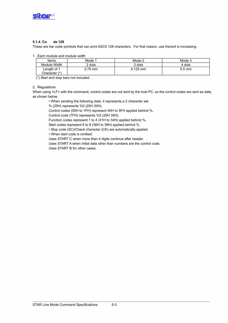
5.1.4. Co de 128 These are bar code symbols that can print ASCII 128 characters. For that reason, use thereof is increasing. 1. Each module and module width
Items Mode 1 Mode 2 Mode 3 Module Width 2 dots 3 dots 4 dots Length of 1
Character (*) 2.75 mm 4.125 mm 5.5 mm
(*) Start and stop bars not included. 2. Regulations When using <LF> with the command, control codes are not sent by the host PC, so the control codes are sent as data, as shown below. • When sending the following data, it represents a 2 character set.
% (25H) represents %0 (25H 30H). Control codes (00H to 1FH) represent 40H to 5FH applied behind %. Control code (7FH) represents %5 (25H 35H). Function codes represent 1 to 4 (31H to 34H) applied behind %. Start codes represent 6 to 8 (36H to 38H) applied behind %.
• Stop code (SC)/Check character (CK) are automatically applied. • When start code is omitted:
Uses START C when more than 4 digits continue after header. Uses START A when initial data other than numbers are the control code. Uses START B for other cases.
――――――――――――――――――――――――――――――――――――――――――――――――――――――――――――――――――――――――――――― STAR Line Mode Command Specifications 5-3
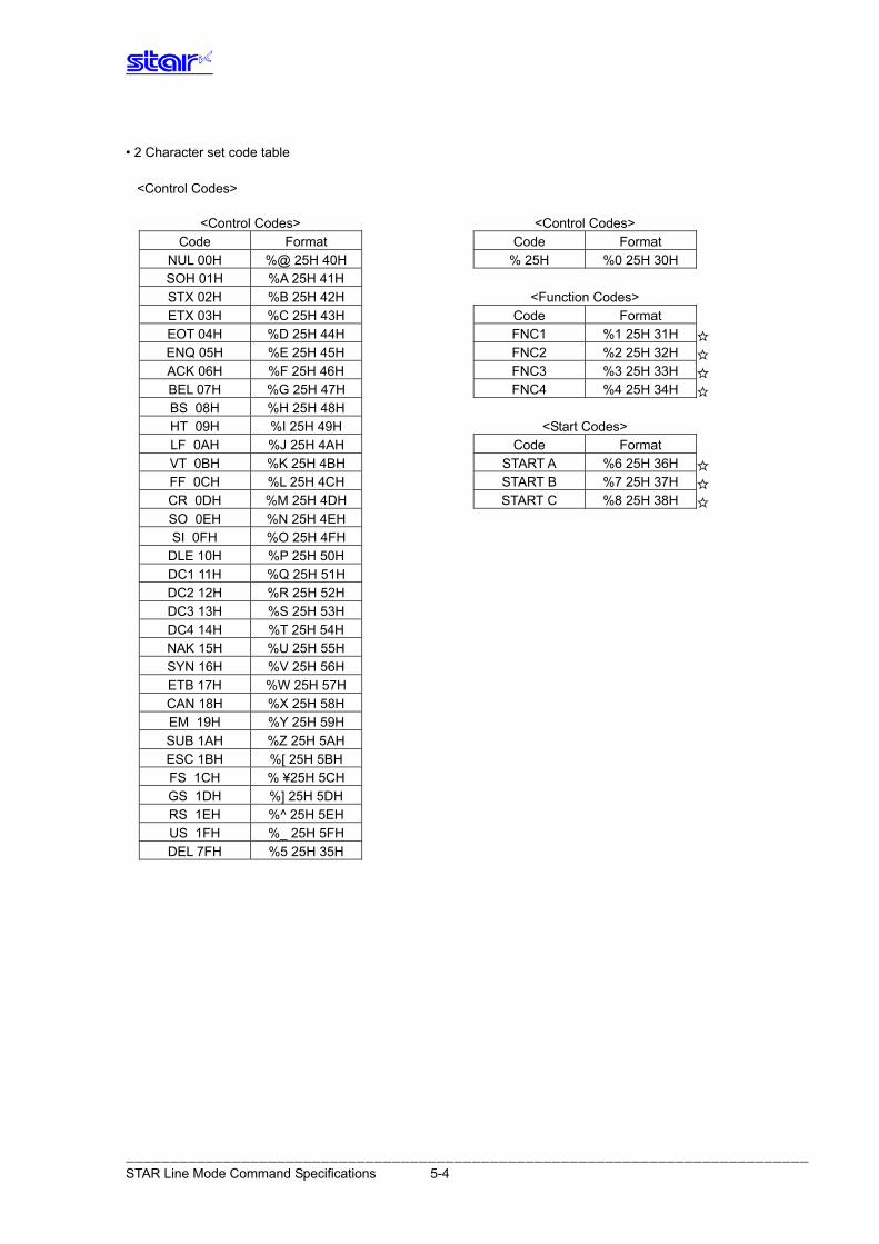
• 2 Character set code table <Control Codes>
<Control Codes> <Control Codes> Code Format Code Format
NUL 00H %@ 25H 40H % 25H %0 25H 30H SOH 01H %A 25H 41H
STX 02H %B 25H 42H <Function Codes> ETX 03H %C 25H 43H Code Format EOT 04H %D 25H 44H FNC1 %1 25H 31H ENQ 05H %E 25H 45H FNC2 %2 25H 32H ACK 06H %F 25H 46H FNC3 %3 25H 33H BEL 07H %G 25H 47H FNC4 %4 25H 34H BS 08H %H 25H 48H
HT 09H %I 25H 49H <Start Codes> LF 0AH %J 25H 4AH Code Format VT 0BH %K 25H 4BH START A %6 25H 36H FF 0CH %L 25H 4CH START B %7 25H 37H CR 0DH %M 25H 4DH START C %8 25H 38H SO 0EH %N 25H 4EH
SI 0FH %O 25H 4FH DLE 10H %P 25H 50H DC1 11H %Q 25H 51H DC2 12H %R 25H 52H DC3 13H %S 25H 53H DC4 14H %T 25H 54H NAK 15H %U 25H 55H SYN 16H %V 25H 56H ETB 17H %W 25H 57H CAN 18H %X 25H 58H EM 19H %Y 25H 59H SUB 1AH %Z 25H 5AH ESC 1BH %[ 25H 5BH FS 1CH % ¥25H 5CH GS 1DH %] 25H 5DH RS 1EH %^ 25H 5EH US 1FH %_ 25H 5FH DEL 7FH %5 25H 35H
――――――――――――――――――――――――――――――――――――――――――――――――――――――――――――――――――――――――――――― STAR Line Mode Command Specifications 5-4
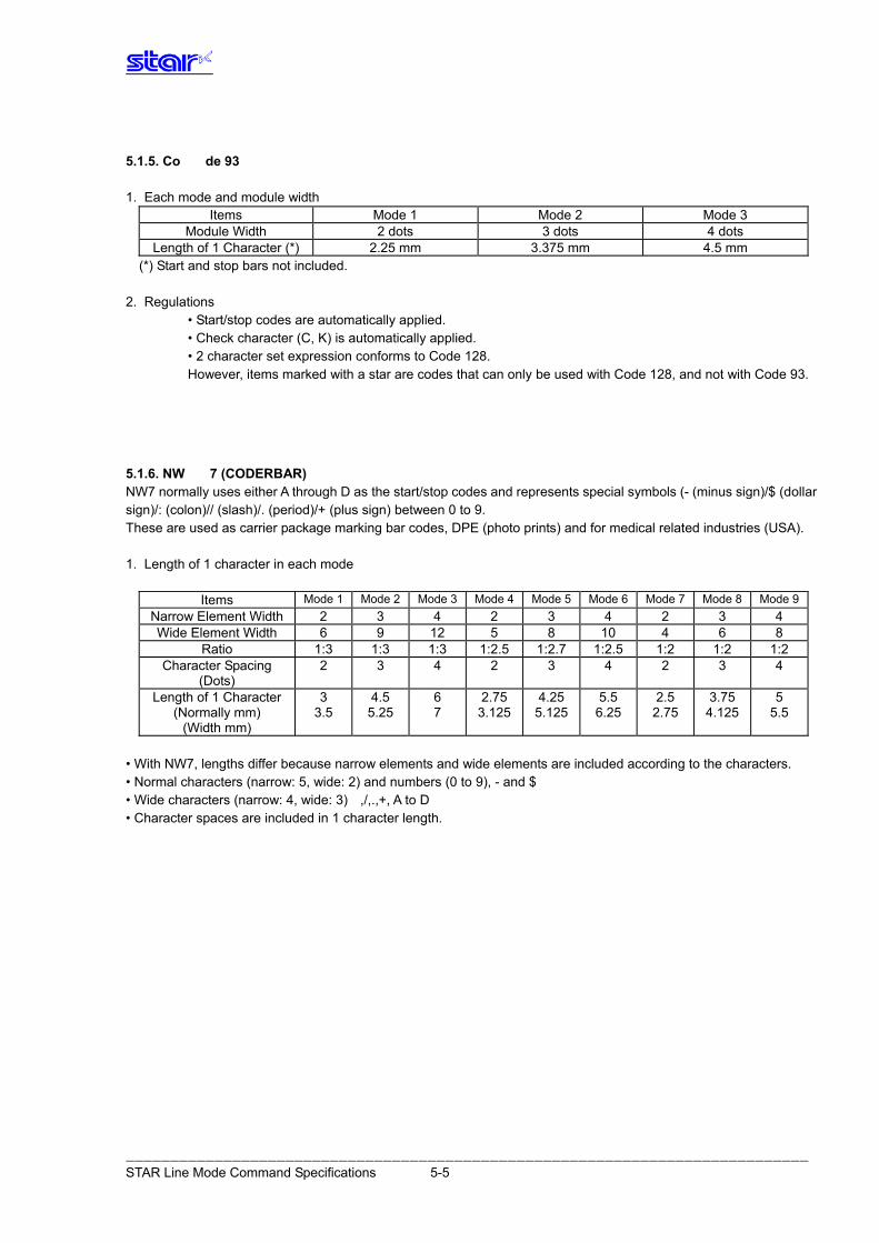
5.1.5. Co de 93 1. Each mode and module width
Items Mode 1 Mode 2 Mode 3 Module Width 2 dots 3 dots 4 dots
Length of 1 Character (*) 2.25 mm 3.375 mm 4.5 mm (*) Start and stop bars not included.
2. Regulations • Start/stop codes are automatically applied. • Check character (C, K) is automatically applied. • 2 character set expression conforms to Code 128.
However, items marked with a star are codes that can only be used with Code 128, and not with Code 93.
5.1.6. NW 7 (CODERBAR) NW7 normally uses either A through D as the start/stop codes and represents special symbols (- (minus sign)/$ (dollar sign)/: (colon)// (slash)/. (period)/+ (plus sign) between 0 to 9. These are used as carrier package marking bar codes, DPE (photo prints) and for medical related industries (USA). 1. Length of 1 character in each mode
Items Mode 1 Mode 2 Mode 3 Mode 4 Mode 5 Mode 6 Mode 7 Mode 8 Mode 9Narrow Element Width 2 3 4 2 3 4 2 3 4 Wide Element Width 6 9 12 5 8 10 4 6 8
Ratio 1:3 1:3 1:3 1:2.5 1:2.7 1:2.5 1:2 1:2 1:2 Character Spacing
(Dots) 2 3 4 2 3 4 2 3 4
Length of 1 Character (Normally mm)
3 4.5 6 2.75 4.25 5.5 2.5 3.75 5 3.5 5.25 7 3.125 5.125 6.25 2.75 4.125 5.5
(Width mm) • With NW7, lengths differ because narrow elements and wide elements are included according to the characters. • Normal characters (narrow: 5, wide: 2) and numbers (0 to 9), - and $ • Wide characters (narrow: 4, wide: 3) ,/,.,+, A to D • Character spaces are included in 1 character length.
――――――――――――――――――――――――――――――――――――――――――――――――――――――――――――――――――――――――――――― STAR Line Mode Command Specifications 5-5
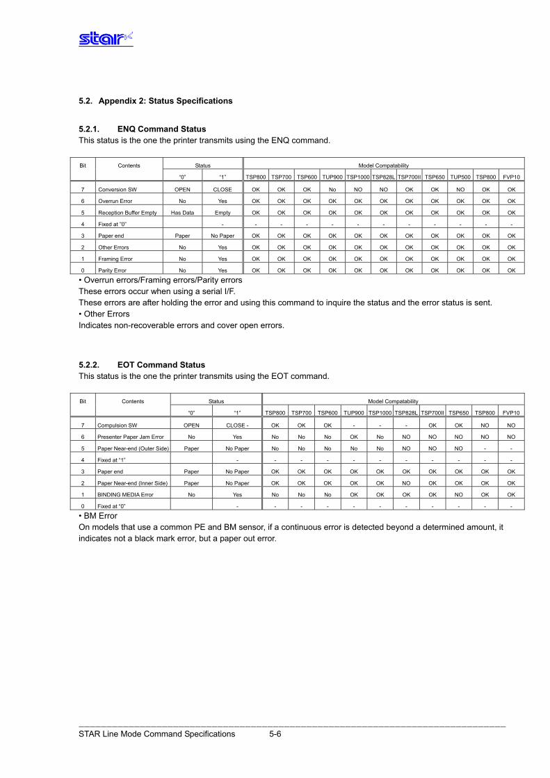
――――――――――――――――――――――――――――――――――――――――――――――――――――――――――――――――――――――――――――― STAR Line Mode Command Specifications 5-6
5.2. Appendix 2: Status Specifications
5.2.1. ENQ Command Status This status is the one the printer transmits using the ENQ command. Bit Contents Status Model Compatability
“0” “1” TSP800 TSP700 TSP600 TUP900 TSP1000 TSP828L TSP700II TSP650 TUP500 TSP800 FVP10
7 Conversion SW OPEN CLOSE OK OK OK No NO NO OK OK NO OK OK
6 Overrun Error No Yes OK OK OK OK OK OK OK OK OK OK OK
5 Reception Buffer Empty Has Data Empty OK OK OK OK OK OK OK OK OK OK OK
4 Fixed at ”0” - - - - - - - - - - - -
3 Paper end Paper No Paper OK OK OK OK OK OK OK OK OK OK OK
2 Other Errors No Yes OK OK OK OK OK OK OK OK OK OK OK
1 Framing Error No Yes OK OK OK OK OK OK OK OK OK OK OK
0 Parity Error No Yes OK OK OK OK OK OK OK OK OK OK OK
• Overrun errors/Framing errors/Parity errors These errors occur when using a serial I/F. These errors are after holding the error and using this command to inquire the status and the error status is sent. • Other Errors Indicates non-recoverable errors and cover open errors.
5.2.2. EOT Command Status This status is the one the printer transmits using the EOT command. Bit Contents Status Model Compatability
“0” “1” TSP800 TSP700 TSP600 TUP900 TSP1000 TSP828L TSP700II TSP650 TSP800 FVP10
7 Compulsion SW OPEN CLOSE - OK OK OK - - - OK OK NO NO
6 Presenter Paper Jam Error No Yes No No No OK No NO NO NO NO NO
5 Paper Near-end (Outer Side) Paper No Paper No No No No No NO NO NO - -
4 Fixed at “1” - - - - - - - - - - -
3 Paper end Paper No Paper OK OK OK OK OK OK OK OK OK OK
2 Paper Near-end (Inner Side) Paper No Paper OK OK OK OK OK NO OK OK OK OK
1 BINDING MEDIA Error No Yes No No No OK OK OK OK NO OK OK
0 Fixed at “0” - - - - - - - - - - -
• BM Error On models that use a common PE and BM sensor, if a continuous error is detected beyond a determined amount, it indicates not a black mark error, but a paper out error.
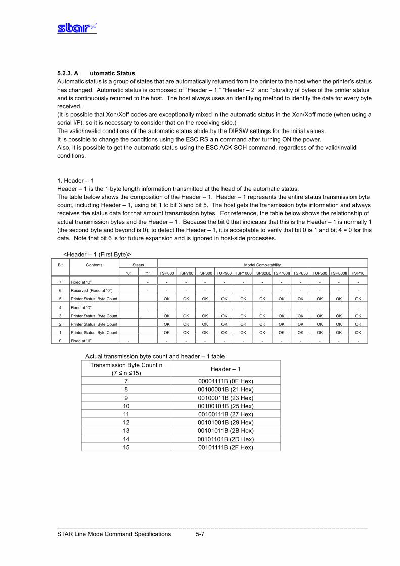
5.2.3. A utomatic Status Automatic status is a group of states that are automatically returned from the printer to the host when the printer’s status has changed. Automatic status is composed of “Header – 1,” “Header – 2” and “plurality of bytes of the printer status and is continuously returned to the host. The host always uses an identifying method to identify the data for every byte received. (It is possible that Xon/Xoff codes are exceptionally mixed in the automatic status in the Xon/Xoff mode (when using a serial I/F), so it is necessary to consider that on the receiving side.) The valid/invalid conditions of the automatic status abide by the DIPSW settings for the initial values. It is possible to change the conditions using the ESC RS a n command after turning ON the power. Also, it is possible to get the automatic status using the ESC ACK SOH command, regardless of the valid/invalid conditions. 1. Header – 1 Header – 1 is the 1 byte length information transmitted at the head of the automatic status. The table below shows the composition of the Header – 1. Header – 1 represents the entire status transmission byte count, including Header – 1, using bit 1 to bit 3 and bit 5. The host gets the transmission byte information and always receives the status data for that amount transmission bytes. For reference, the table below shows the relationship of actual transmission bytes and the Header – 1. Because the bit 0 that indicates that this is the Header – 1 is normally 1 (the second byte and beyond is 0), to detect the Header – 1, it is acceptable to verify that bit 0 is 1 and bit 4 = 0 for this data. Note that bit 6 is for future expansion and is ignored in host-side processes.
<Header – 1 (First Byte)> Bit Contents Status Model Compatability
“0” “1” TSP800 TSP700 TSP600 TUP900 TSP1000 TSP828L TSP700II TSP650 TUP500 TSP800II FVP10
7 Fixed at “0” - - - - - - - - - - - -
6 Reserved (Fixed at “0”) - - - - - - - - - - - -
5 Printer Status Byte Count OK OK OK OK OK OK OK OK OK OK OK
4 Fixed at “0” - - - - - - - - - - - -
3 Printer Status Byte Count OK OK OK OK OK OK OK OK OK OK OK
2 Printer Status Byte Count OK OK OK OK OK OK OK OK OK OK OK
1 Printer Status Byte Count OK OK OK OK OK OK OK OK OK OK OK
0 Fixed at “1” - - - - - - - - - - - -
Actual transmission byte count and header – 1 table
Transmission Byte Count n Header – 1
(7 ≤ n ≤15) 7 00001111B (0F Hex) 8 00100001B (21 Hex) 9 00100011B (23 Hex) 10 00100101B (25 Hex) 11 00100111B (27 Hex) 12 00101001B (29 Hex) 13 00101011B (2B Hex) 14 00101101B (2D Hex) 15 00101111B (2F Hex)
――――――――――――――――――――――――――――――――――――――――――――――――――――――――――――――――――――――――――――― STAR Line Mode Command Specifications 5-7
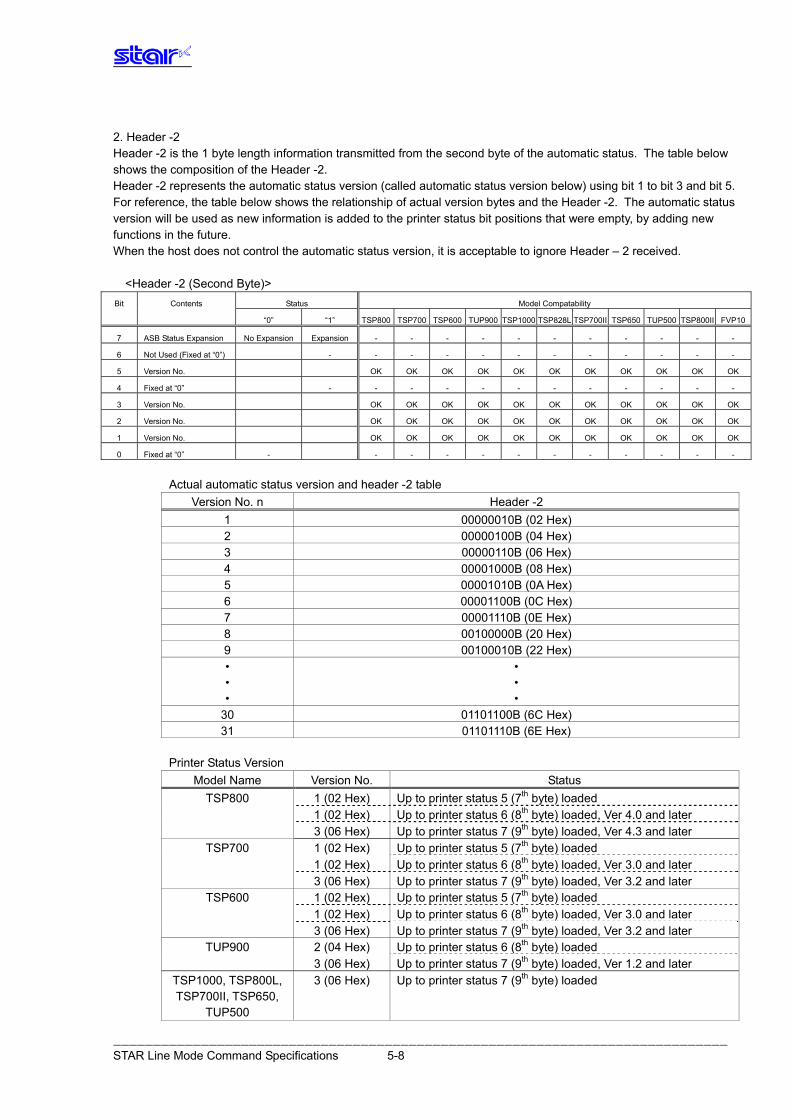
2. Header -2 Header -2 is the 1 byte length information transmitted from the second byte of the automatic status. The table below shows the composition of the Header -2. Header -2 represents the automatic status version (called automatic status version below) using bit 1 to bit 3 and bit 5. For reference, the table below shows the relationship of actual version bytes and the Header -2. The automatic status version will be used as new information is added to the printer status bit positions that were empty, by adding new functions in the future. When the host does not control the automatic status version, it is acceptable to ignore Header – 2 received.
<Header -2 (Second Byte)> Bit Contents Status Model Compatability
“0” “1” TSP800 TSP700 TSP600 TUP900 TSP1000 TSP828L TSP700II TSP650 TUP500 TSP800II FVP10
7 ASB Status Expansion No Expansion Expansion - - - - - - - - - - -
6 Not Used (Fixed at “0”) - - - - - - - - - - - -
5 Version No. OK OK OK OK OK OK OK OK OK OK OK
4 Fixed at “0” - - - - - - - - - - - -
3 Version No. OK OK OK OK OK OK OK OK OK OK OK
2 Version No. OK OK OK OK OK OK OK OK OK OK OK
1 Version No. OK OK OK OK OK OK OK OK OK OK OK
0 Fixed at “0” - - - - - - - - - - - -
Actual automatic status version and header -2 table
Version No. n Header -2 1 00000010B (02 Hex) 2 00000100B (04 Hex) 3 00000110B (06 Hex) 4 00001000B (08 Hex) 5 00001010B (0A Hex) 6 00001100B (0C Hex) 7 00001110B (0E Hex) 8 00100000B (20 Hex) 9 00100010B (22 Hex)
• • • • • •
30 01101100B (6C Hex) 31 01101110B (6E Hex)
Printer Status Version
Model Name Version No. Status Up to printer status 5 (7th byte) loaded TSP800 1 (02 Hex) Up to printer status 6 (8th byte) loaded, Ver 4.0 and later 1 (02 Hex) Up to printer status 7 (9th byte) loaded, Ver 4.3 and later 3 (06 Hex) Up to printer status 5 (7th byte) loaded TSP700 1 (02 Hex) Up to printer status 6 (8th byte) loaded, Ver 3.0 and later 1 (02 Hex) Up to printer status 7 (9th byte) loaded, Ver 3.2 and later 3 (06 Hex) Up to printer status 5 (7th byte) loaded TSP600 1 (02 Hex) Up to printer status 6 (8th byte) loaded, Ver 3.0 and later 1 (02 Hex) Up to printer status 7 (9th byte) loaded, Ver 3.2 and later 3 (06 Hex) Up to printer status 6 (8th byte) loaded TUP900 2 (04 Hex) Up to printer status 7 (9th byte) loaded, Ver 1.2 and later 3 (06 Hex) Up to printer status 7 (9th byte) loaded 3 (06 Hex) TSP1000, TSP800L,
TSP700II, TSP650, TUP500
――――――――――――――――――――――――――――――――――――――――――――――――――――――――――――――――――――――――――――― STAR Line Mode Command Specifications 5-8
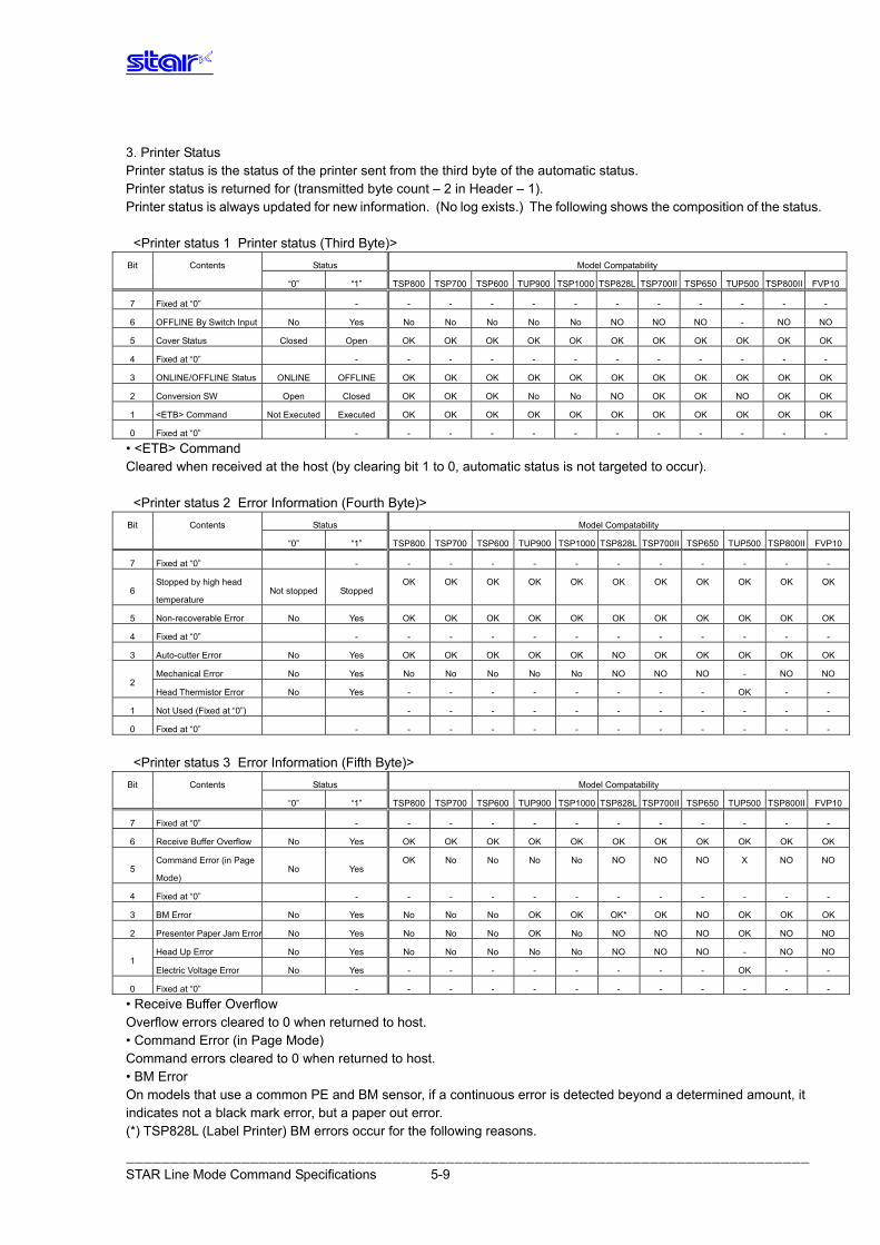
――――――――――――――――――――――――――――――――――――――――――――――――――――――――――――――――――――――――――――― STAR Line Mode Command Specifications 5-9
3. Printer Status Printer status is the status of the printer sent from the third byte of the automatic status. Printer status is returned for (transmitted byte count – 2 in Header – 1). Printer status is always updated for new information. (No log exists.) The following shows the composition of the status. <Printer status 1 Printer status (Third Byte)> Bit Contents Status Model Compatability
“0” “1” TSP800 TSP700 TSP600 TUP900 TSP1000 TSP828L TSP700II TSP650 TUP500 TSP800II FVP10
7 Fixed at “0” - - - - - - - - - - - -
6 OFFLINE By Switch Input No Yes No No No No No NO NO NO - NO NO
5 Cover Status Closed Open OK OK OK OK OK OK OK OK OK OK OK
4 Fixed at “0” - - - - - - - - - - - -
3 ONLINE/OFFLINE Status ONLINE OFFLINE OK OK OK OK OK OK OK OK OK OK OK
2 Conversion SW Open Closed OK OK OK No No NO OK OK NO OK OK
1 <ETB> Command Not Executed Executed OK OK OK OK OK OK OK OK OK OK OK
0 Fixed at “0” - - - - - - - - - - - -
• <ETB> Command Cleared when received at the host (by clearing bit 1 to 0, automatic status is not targeted to occur). <Printer status 2 Error Information (Fourth Byte)> Bit Contents Status Model Compatability
“0” “1” TSP800 TSP700 TSP600 TUP900 TSP1000 TSP828L TSP700II TSP650 TUP500 TSP800II FVP10
7 Fixed at “0” - - - - - - - - - - - -
6 Stopped by high head
temperature Not stopped Stopped
OK OK OK OK OK OK OK OK OK OK OK
5 Non-recoverable Error No Yes OK OK OK OK OK OK OK OK OK OK OK
4 Fixed at “0” - - - - - - - - - - - -
3 Auto-cutter Error No Yes OK OK OK OK OK NO OK OK OK OK OK
Mechanical Error No Yes No No No No No NO NO NO - NO NO 2
Head Thermistor Error No Yes - - - - - - - - OK - -
1 Not Used (Fixed at “0”) - - - - - - - - - - -
0 Fixed at “0” - - - - - - - - - - - -
<Printer status 3 Error Information (Fifth Byte)> Bit Contents Status Model Compatability
“0” “1” TSP800 TSP700 TSP600 TUP900 TSP1000 TSP828L TSP700II TSP650 TUP500 TSP800II FVP10
7 Fixed at “0” - - - - - - - - - - - -
6 Receive Buffer Overflow No Yes OK OK OK OK OK OK OK OK OK OK OK
5 Command Error (in Page
Mode) No Yes
OK No No No No NO NO NO X NO NO
4 Fixed at “0” - - - - - - - - - - - -
3 BM Error No Yes No No No OK OK OK* OK NO OK OK OK
2 Presenter Paper Jam Error No Yes No No No OK No NO NO NO OK NO NO
Head Up Error No Yes No No No No No NO NO NO - NO NO 1
Electric Voltage Error No Yes - - - - - - - - OK - -
0 Fixed at “0” - - - - - - - - - - - -
• Receive Buffer Overflow Overflow errors cleared to 0 when returned to host. • Command Error (in Page Mode) Command errors cleared to 0 when returned to host. • BM Error On models that use a common PE and BM sensor, if a continuous error is detected beyond a determined amount, it indicates not a black mark error, but a paper out error. (*) TSP828L (Label Printer) BM errors occur for the following reasons.
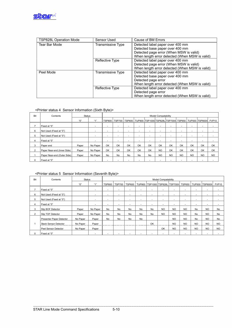
――――――――――――――――――――――――――――――――――――――――――――――――――――――――――――――――――――――――――――― STAR Line Mode Command Specifications 5-10
TSP828L Operation Mode Sensor Used Cause of BM Errors
Transmissive Type Detected label paper over 400 mm Detected base paper over 400 mm Detected page error (When MSW is valid) When length error detected (When MSW is valid)
Tear Bar Mode
Reflective Type Detected label paper over 400 mm Detected page error (When MSW is valid) When length error detected (When MSW is valid)
Transmissive Type Detected label paper over 400 mm Detected base paper over 400 mm Detected page error When length error detected (When MSW is valid)
Peel Mode
Reflective Type Detected label paper over 400 mm Detected page error When length error detected (When MSW is valid)
<Printer status 4 Sensor Information (Sixth Byte)> Bit Contents Status Model Compatability
“0” “1” TSP800 TSP700 TSP600 TUP900 TSP1000 TSP828L TSP700II TSP650 TUP500 TSP800II FVP10
7 Fixed at “0” - - - - - - - - - - - -
6 Not Used (Fixed at “0”) - - - - - - - - - - - -
5 Not Used (Fixed at “0”) - - - - - - - - - - - -
4 Fixed at “0” - - - - - - - - - - - -
3 Paper end Paper No Paper OK OK OK OK OK OK OK OK OK OK OK
2 Paper Near-end (Inner Side) Paper No Paper OK OK OK OK OK NO OK OK OK OK OK
1 Paper Near-end (Outer Side) Paper No Paper No No No No No NO NO NO NO NO NO
0 Fixed at “0” - - - - - - - - - - - -
<Printer status 5 Sensor Information (Seventh Byte)> Bit Contents Status Model Compatability
“0” “1” TSP800 TSP700 TSP600 TUP900 TSP1000 TSP828L TSP700II TSP650 TUP500 TSP800II FVP10
7 Fixed at “0” - - - - - - - - - - - -
6 Not Used (Fixed at “0”) - - - - - - - - - - - -
5 Not Used (Fixed at “0”) - - - - - - - - - - - -
4 Fixed at “0” - - - - - - - - - - - -
3 Slip BOF Detector Paper No Paper No No No No No NO NO NO No NO No
2 Slip TOF Detector Paper No Paper No No No No No NO NO NO No NO No
Presenter Paper Detector No Paper Paper No No No No NO NO No NO No
Stack Sensor Detector No Paper Paper OK NO NO NO NO NO 1
Peel Sensor Detector No Paper Paper OK NO NO NO NO NO
0 Fixed at “0” - - - - - - - - - - - -
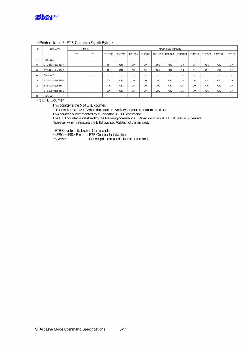
<Printer status 6 ETB Counter (Eighth Byte)> Bit Contents Status Model Compatability
“0” “1” TSP800 TSP700 TSP600 TUP900 TSP1000 TSP828L TSP700II TSP650 TUP500 TSP800II FVP10
7 Fixed at 0 - - - - - - - - - - - -
6 ETB Counter Bit-4 OK OK OK OK OK OK OK OK OK OK OK
5 ETB Counter Bit-3 OK OK OK OK OK OK OK OK OK OK OK
4 Fixed at 0 - - - - - - - - - - - -
3 ETB Counter Bit-2 OK OK OK OK OK OK OK OK OK OK OK
2 ETB Counter Bit-1 OK OK OK OK OK OK OK OK OK OK OK
1 ETB Counter Bit-0 OK OK OK OK OK OK OK OK OK OK OK
0 Fixed at 0 - - - - - - - - - - - -
(*) ETB Counter This counter is the 5 bit ETB counter.
(It counts from 0 to 31. When the counter overflows, it counts up from 31 to 0.) This counter is incremented by 1 using the <ETB> command. The ETB counter is initialized by the following commands. When doing so, ASB ETB status is cleared. However, when initializing the ETB counter, ASB is not transmitted.
<ETB Counter Initialization Commands> • <ESC> <RS> E n : ETB Counter Initialization • <CAN> : Cancel print data and initialize commands
――――――――――――――――――――――――――――――――――――――――――――――――――――――――――――――――――――――――――――― STAR Line Mode Command Specifications 5-11
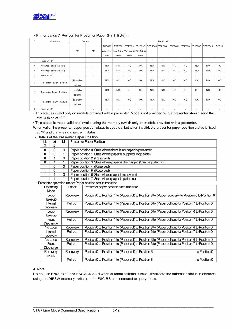
<Printer status 7 Position for Presenter Paper (Ninth Byte)> Bit Contents Status By model
TSP800 TSP700 TSP600 TUP900 TSP1000 TSP828L TSP700II TSP650 TUP500 TSP800II FVP10
“0” “1” Ver. 4.3 or
later
Ver. 3.2 or
later
Ver. 3.2 or
later
Ver. 1.2 or
later
7 Fixed at “0” - - - - - - - - - - - -
6 Not Used (Fixed at “0”) - NO NO NO OK NO NO NO NO NO NO NO
5 Not Used (Fixed at “0”) - NO NO NO OK NO NO NO NO NO NO NO
4 Fixed at “0” - - - - - - - - - - - -
(See table
below)
NO NO NO OK NO NO NO NO OK NO NO 3 Presenter Paper Position
(See table
below)
NO NO NO OK NO NO NO NO OK NO NO 2 Presenter Paper Position
(See table
below)
NO NO NO OK NO NO NO NO OK NO NO 1 Presenter Paper Position
0 Fixed at “0” - - - - - - - - - - - -
• This status is valid only on models provided with a presenter. Models not provided with a presenter should send this status fixed at “0.”
• This status is made valid and invalid using the memory switch only on models provided with a presenter. When valid, the presenter paper position status is updated, but when invalid, the presenter paper position status is fixed
at “0” and there is no change in status. • Details of the Presenter Paper Position
bit 3
bit 2
bit 1
Presenter Paper Position
0 0 0 Paper position 0 State where there is no paper in presenter 0 0 1 Paper position 1 State where paper is supplied (loop state) 0 1 0 Paper position 2 (Reserved) 0 1 1 Paper position 3 State where paper is discharged (Can be pulled out) 1 0 0 Paper position 4 (Reserved) 1 0 1 Paper position 5 (Reserved) 1 1 0 Paper position 6 State where paper is recovered 1 1 1 Paper position 7 State where paper is pulled out.
• Presenter operation mode: Paper position status transition Operating
Mode Paper Presenter paper position state transition
Loop Take-up
Recovery Position 0 to Position 1 to (Paper cut) to Position 3 to (Paper recovery) to Position 6 to Position 0
Internal recovery
Pull out Position 0 to Position 1 to (Paper cut) to Position 3 to (Paper pull out) to Position 7 to Position 0
Loop Take-up
Recovery Position 0 to Position 1 to (Paper cut) to Position 3 to (Paper pull out) to Position 6 to Position 0
Front Discharge
Pull out Position 0 to Position 1 to (Paper cut) to Position 3 to (Paper pull out) to Position 7 to Position 0
No Loop Recovery Position 0 to Position 1 to (Paper cut) to Position 3 to (Paper pull out) to Position 6 to Position 0 Internal recovery
Pull out Position 0 to Position 1 to (Paper cut) to Position 3 to (Paper pull out) to Position 7 to Position 0
No Loop Recovery Position 0 to Position 1 to (Paper cut) to Position 3 to (Paper pull out) to Position 6 to Position 0 Front
Discharge Pull out Position 0 to Position 1 to (Paper cut) to Position 3 to (Paper pull out) to Position 7 to Position 0
Recovery Invalid
Recovery Position 0 to Position 1 to (Paper cut) to Position 6 to Position 0
Pull out Position 0 to Position 1 to (Paper cut) to Position 6 to Position 0 4. Note Do not use ENQ, EOT, and ESC ACK SOH when automatic status is valid. Invalidate the automatic status in advance using the DIPSW (memory switch) or the ESC RS a n command to query these.
――――――――――――――――――――――――――――――――――――――――――――――――――――――――――――――――――――――――――――― STAR Line Mode Command Specifications 5-12
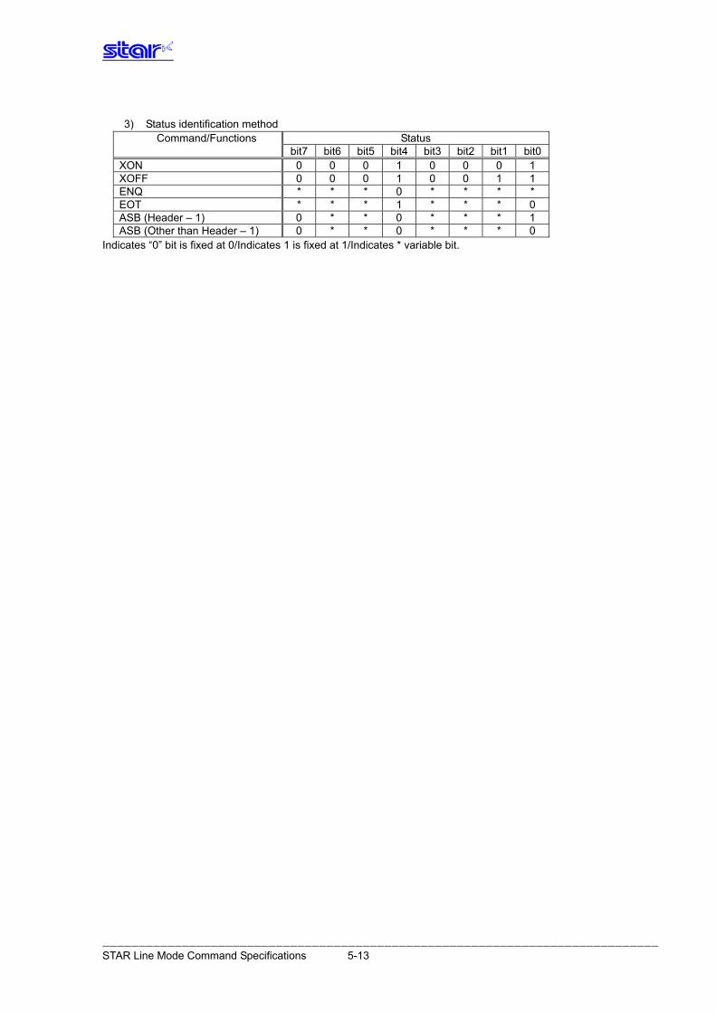
3) Status identification method
Command/Functions Status bit7 bit6 bit5 bit4 bit3 bit2 bit1 bit0 XON 0 0 0 1 0 0 0 1 XOFF 0 0 0 1 0 0 1 1 ENQ * * * 0 * * * * EOT * * * 1 * * * 0 ASB (Header – 1) 0 * * 0 * * * 1 ASB (Other than Header – 1) 0 * * 0 * * * 0
Indicates “0” bit is fixed at 0/Indicates 1 is fixed at 1/Indicates * variable bit.
――――――――――――――――――――――――――――――――――――――――――――――――――――――――――――――――――――――――――――― STAR Line Mode Command Specifications 5-13
5.2.4 Prin ter status transmission specification when using Ethernet I/F and Wireless LAN I/F The following describes printer status transmission specifications when using an Ethernet I/F and wireless LAN I/F. 1) Transmission Format:
• When transmitting only STAR ASB: STAR ASB (Second Byte Bit 7 = 1) + Length (Length = 0x0000) • When transmitting printer status other than STAR ASB: STAR ASB (Second Byte Bit 7 = 1) + Length + Status Data
<Length Details> • 2 byte value indicating status data byte count (0x0000 ≤ Length ≤ 0x0200) • When the status data is 10 bytes: Length = 0x000a • Apply Length = 0x0000 to only transmit STAR ASB. • When STAR ASB Second Byte Bit-7 is applied with Length, set to Bit-7 = 1
In analysis of printer statuses, the total number of bytes of the ASB according to the STAR ASB First byte is detected, and it is detected whether Length has been applied by the second byte Bit-7 of STAR ASB. Depending on the length, by acquiring subsequent status data byte counts, it is possible to analyze the status. 2) Status data transmission format Status type + separator character 1 + data type + status length + printer status + separator character 2 1. Status Type (2byte or 4Byte)
• First and Second Bytes Indicate the cause to generate a printer status. • “00”: Reserved • “01” to ”09”: Star real-time status request command • ”10” to ”49”: Star status request command • “50”: Reserved • “51” to ”59”: Reserved • “60” to ”99”: Reserved • “A0” to “FF”: Reserved • Third and Fourth Bytes When a cause occurs, these indicate the command n parameter. If there is no n parameter, the third and fourth bytes can be omitted. <Ex.> When n = 0x31 using the ESC SYN 3 n command, the third and fourth bytes are “31.”
――――――――――――――――――――――――――――――――――――――――――――――――――――――――――――――――――――――――――――― STAR Line Mode Command Specifications 5-14
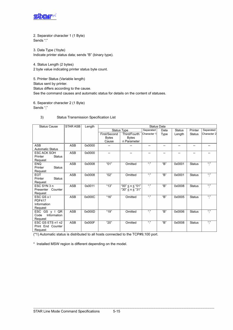
2. Separator character 1 (1 Byte) Sends “:” 3. Data Type (1byte) Indicate printer status data; sends “B” (binary type). 4. Status Length (2 bytes) 2 byte value indicating printer status byte count. 5. Printer Status (Variable length) Status sent by printer. Status differs according to the cause. See the command causes and automatic status for details on the content of statuses. 6. Separator character 2 (1 Byte) Sends “;”
3) Status Transmission Specification List
Status Cause STAR ASB Length Status Data Status Type Data Status PrinterSeparated Separated
Type Length First/Second Bytes
Third/Fourth Bytes
StatusCharacter 1 Character 2
Cause n ParameterASB 0x0000 -- -- -- -- -- -- -- ASB
Automatic Status ESC ACK SOH Printer Status Request
ASB 0x0000 -- -- -- -- -- -- --
ENQ Printer Status Request
ASB 0x0008 “01” Omitted “:” “B” 0x0001 “;” Status
EOT Printer Status Request
ASB 0x0008 “02” Omitted “:” “B” 0x0001 “;” Status
ASB 0x0011 “13” “:” “B” 0x0008 “;” ESC SYN 3 n “00” ≤Presenter Counter Request
n ≤ “01” Status“30” ≤ n ≤ ”31”
ASB 0x000C “16” Omitted “:” “B” 0x0005 “;” ESC GS x I StatusPDF417 Information Request
ASB 0x000D “19” Omitted “:” “B” 0x0006 “;” ESC GS y I QR Code Information Request
Status
ASB 0x000F “20” Omitted “:” “B” 0x0008 “;” ESC GS ETS n1 n2 Print End Counter Request
Status
(*1) Automatic status is distributed to all hosts connected to the TCP#9,100 port. * Installed MSW region is different depending on the model.
――――――――――――――――――――――――――――――――――――――――――――――――――――――――――――――――――――――――――――― STAR Line Mode Command Specifications 5-15
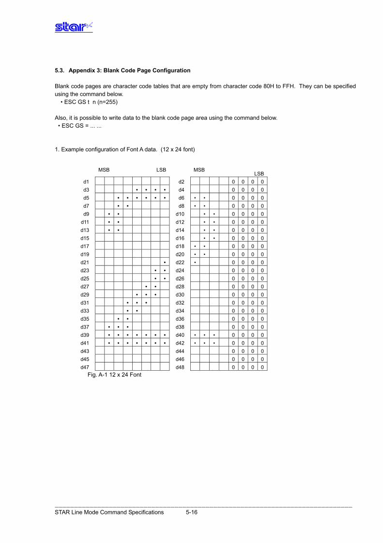
――――――――――――――――――――――――――――――――――――――――――――――――――――――――――――――――――――――――――――― STAR Line Mode Command Specifications 5-16
5.3. Appendix 3: Blank Code Page Configuration Blank code pages are character code tables that are empty from character code 80H to FFH. They can be specified using the command below.
• ESC GS t n (n=255) Also, it is possible to write data to the blank code page area using the command below. • ESC GS = ... ... 1. Example configuration of Font A data. (12 x 24 font)
MSB LSB MSB
LSB
d1 d2 0 0 0 0 d3 • • • • d4 0 0 0 0 d5 • • • • • • d6 • • 0 0 0 0 d7 • • d8 • • 0 0 0 0 d9 • • d10 • • 0 0 0 0
d11 • • d12 • • 0 0 0 0 d13 • • d14 • • 0 0 0 0 d15 d16 • • 0 0 0 0 d17 d18 • • 0 0 0 0 d19 d20 • • 0 0 0 0 d21 • d22 • 0 0 0 0 d23 • • d24 0 0 0 0 d25 • • d26 0 0 0 0 d27 • • d28 0 0 0 0 d29 • • • d30 0 0 0 0 d31 • • • d32 0 0 0 0 d33 • • d34 0 0 0 0 d35 • • d36 0 0 0 0 d37 • • • d38 0 0 0 0 d39 • • • • • • • d40 • • • 0 0 0 0 d41 • • • • • • • d42 • • • 0 0 0 0 d43 d44 0 0 0 0 d45 d46 0 0 0 0 d47 d48 0 0 0 0
Fig. A-1 12 x 24 Font
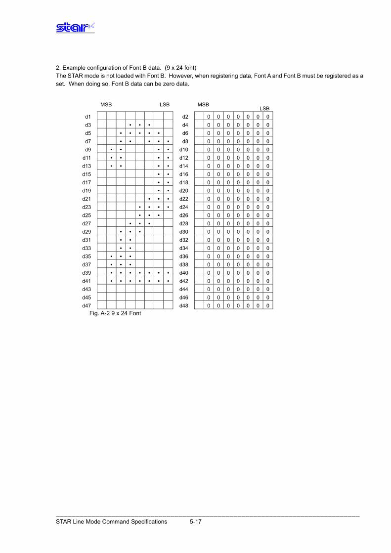
――――――――――――――――――――――――――――――――――――――――――――――――――――――――――――――――――――――――――――― STAR Line Mode Command Specifications 5-17
2. Example configuration of Font B data. (9 x 24 font) The STAR mode is not loaded with Font B. However, when registering data, Font A and Font B must be registered as a set. When doing so, Font B data can be zero data.
MSB LSB MSB
LSB
d1 d2 0 0 0 0 0 0 0 d3 • • • d4 0 0 0 0 0 0 0 d5 • • • • • d6 0 0 0 0 0 0 0 d7 • • • • • d8 0 0 0 0 0 0 0 d9 • • • • d10 0 0 0 0 0 0 0
d11 • • • • d12 0 0 0 0 0 0 0 d13 • • • • d14 0 0 0 0 0 0 0 d15 • • d16 0 0 0 0 0 0 0 d17 • • d18 0 0 0 0 0 0 0 d19 • • d20 0 0 0 0 0 0 0 d21 • • • d22 0 0 0 0 0 0 0 d23 • • • • d24 0 0 0 0 0 0 0 d25 • • • d26 0 0 0 0 0 0 0 d27 • • • d28 0 0 0 0 0 0 0 d29 • • • d30 0 0 0 0 0 0 0 d31 • • d32 0 0 0 0 0 0 0 d33 • • d34 0 0 0 0 0 0 0 d35 • • • d36 0 0 0 0 0 0 0 d37 • • • d38 0 0 0 0 0 0 0 d39 • • • • • • • d40 0 0 0 0 0 0 0 d41 • • • • • • • d42 0 0 0 0 0 0 0 d43 d44 0 0 0 0 0 0 0 d45 d46 0 0 0 0 0 0 0 d47 d48 0 0 0 0 0 0 0
Fig. A-2 9 x 24 Font
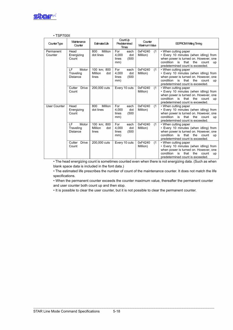
• TSP700II Count Up
Predetermined Times
Maintenance Counter
Counter Maximum Value Counter Type Estimated Life EEPROM Writing Timing
Permanent Counter
Head Energizing Count
800 Million dot lines
For each 4,000 dot lines (500 mm)
0xF4240 (1 Million)
• When cutting paper • Every 10 minutes (when idling) from when power is turned on. However, one condition is that the count up predetermined count is exceeded.
LF Motor Traveling Distance
100 km; 800 Million dot lines
For each 4,000 dot lines (500 mm)
0xF4240 (1 Million)
• When cutting paper • Every 10 minutes (when idling) from when power is turned on. However, one condition is that the count up predetermined count is exceeded.
Cutter Drive Count
200,000 cuts Every 10 cuts 0xF4240 (1 Million)
• When cutting paper • Every 10 minutes (when idling) from when power is turned on. However, one condition is that the count up predetermined count is exceeded.
User Counter Head Energizing Count
800 Million dot lines
For each 4,000 dot lines (500 mm)
0xF4240 (1 Million)
• When cutting paper • Every 10 minutes (when idling) from when power is turned on. However, one condition is that the count up predetermined count is exceeded.
LF Motor Traveling Distance
100 km; 800 Million dot lines
For each 4,000 dot lines (500 mm)
0xF4240 (1 Million)
• When cutting paper • Every 10 minutes (when idling) from when power is turned on. However, one condition is that the count up predetermined count is exceeded.
Cutter Drive Count
200,000 cuts Every 10 cuts 0xF4240 (1 Million)
• When cutting paper • Every 10 minutes (when idling) from when power is turned on. However, one condition is that the count up predetermined count is exceeded.
• The head energizing count is sometimes counted even when there is not energizing data. (Such as when blank space data is included in the font data.) • The estimated life prescribes the number of count of the maintenance counter. It does not match the life specifications. • When the permanent counter exceeds the counter maximum value, thereafter the permanent counter and user counter both count up and then stop. • It is possible to clear the user counter, but it is not possible to clear the permanent counter.
――――――――――――――――――――――――――――――――――――――――――――――――――――――――――――――――――――――――――――― STAR Line Mode Command Specifications 5-18
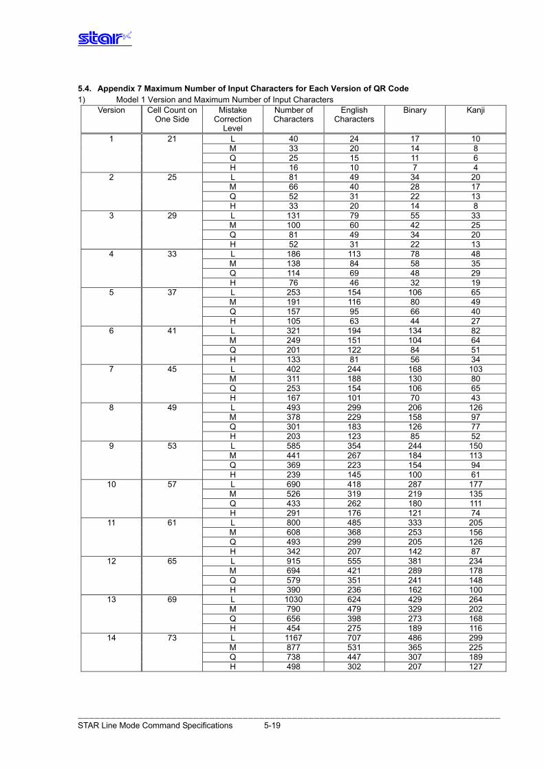
――――――――――――――――――――――――――――――――――――――――――――――――――――――――――――――――――――――――――――― STAR Line Mode Command Specifications 5-19
5.4. Appendix 7 Maximum Number of Input Characters for Each Version of QR Code 1) Model 1 Version and Maximum Number of Input Characters
Version Cell Count on One Side
Mistake Correction
Level
Number of Characters
English Characters
Binary Kanji
1 21 L 40 24 17 10 M 33 20 14 8 Q 25 15 11 6 H 16 10 7 4
2 25 L 81 49 34 20 M 66 40 28 17 Q 52 31 22 13 H 33 20 14 8
3 29 L 131 79 55 33 M 100 60 42 25 Q 81 49 34 20 H 52 31 22 13
4 33 L 186 113 78 48 M 138 84 58 35 Q 114 69 48 29 H 76 46 32 19
5 37 L 253 154 106 65 M 191 116 80 49 Q 157 95 66 40 H 105 63 44 27
6 41 L 321 194 134 82 M 249 151 104 64 Q 201 122 84 51 H 133 81 56 34
7 45 L 402 244 168 103 M 311 188 130 80 Q 253 154 106 65 H 167 101 70 43
8 49 L 493 299 206 126 M 378 229 158 97 Q 301 183 126 77 H 203 123 85 52
9 53 L 585 354 244 150 M 441 267 184 113 Q 369 223 154 94 H 239 145 100 61
10 57 L 690 418 287 177 M 526 319 219 135 Q 433 262 180 111 H 291 176 121 74
11 61 L 800 485 333 205 M 608 368 253 156 Q 493 299 205 126 H 342 207 142 87
12 65 L 915 555 381 234 M 694 421 289 178 Q 579 351 241 148 H 390 236 162 100
13 69 L 1030 624 429 264 M 790 479 329 202 Q 656 398 273 168 H 454 275 189 116
14 73 L 1167 707 486 299 M 877 531 365 225 Q 738 447 307 189 H 498 302 207 127
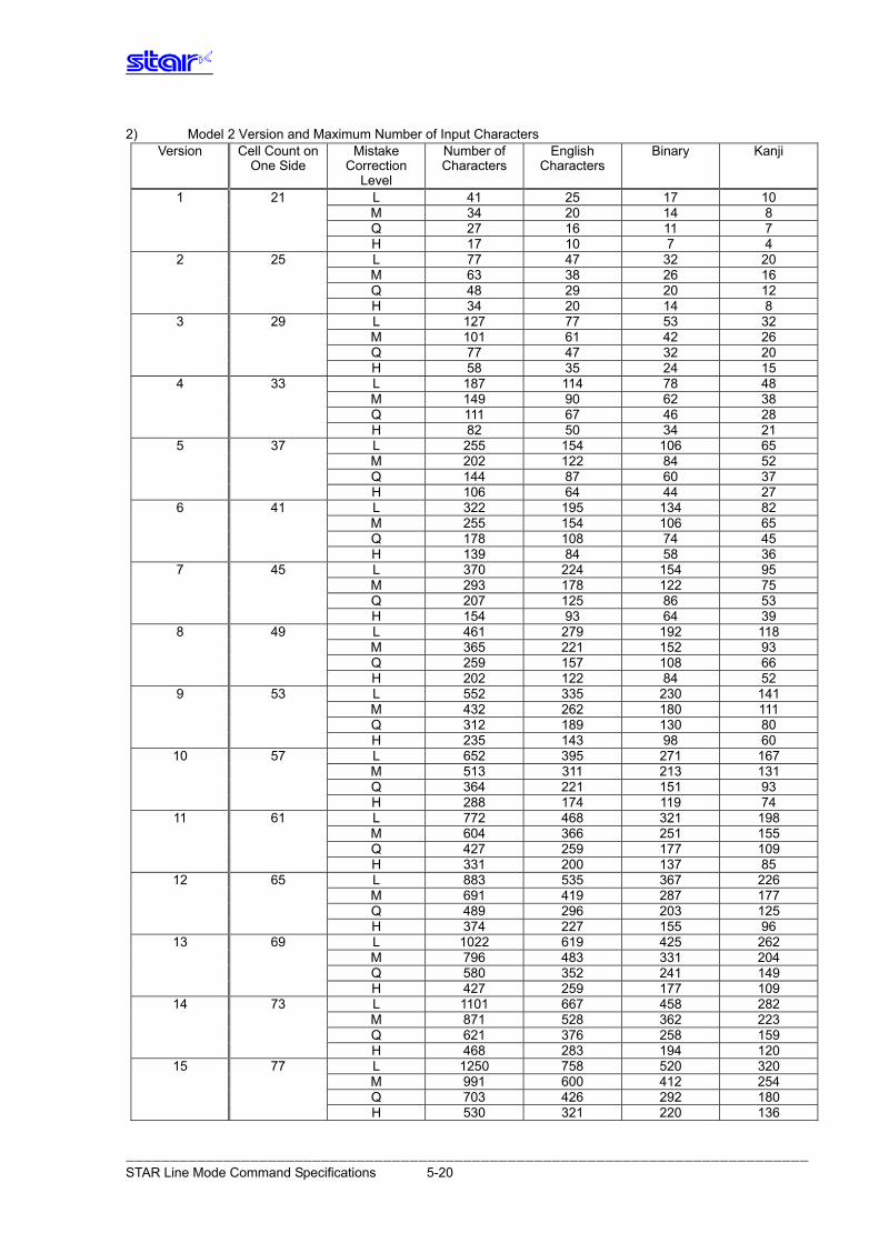
――――――――――――――――――――――――――――――――――――――――――――――――――――――――――――――――――――――――――――― STAR Line Mode Command Specifications 5-20
2) Model 2 Version and Maximum Number of Input Characters Version Cell Count on
One Side Mistake
Correction Level
Number of Characters
English Characters
Binary Kanji
1 21 L 41 25 17 10 M 34 20 14 8 Q 27 16 11 7 H 17 10 7 4
2 25 L 77 47 32 20 M 63 38 26 16 Q 48 29 20 12 H 34 20 14 8
3 29 L 127 77 53 32 M 101 61 42 26 Q 77 47 32 20 H 58 35 24 15
4 33 L 187 114 78 48 M 149 90 62 38 Q 111 67 46 28 H 82 50 34 21
5 37 L 255 154 106 65 M 202 122 84 52 Q 144 87 60 37 H 106 64 44 27
6 41 L 322 195 134 82 M 255 154 106 65 Q 178 108 74 45 H 139 84 58 36
7 45 L 370 224 154 95 M 293 178 122 75 Q 207 125 86 53 H 154 93 64 39
8 49 L 461 279 192 118 M 365 221 152 93 Q 259 157 108 66 H 202 122 84 52
9 53 L 552 335 230 141 M 432 262 180 111 Q 312 189 130 80 H 235 143 98 60
10 57 L 652 395 271 167 M 513 311 213 131 Q 364 221 151 93 H 288 174 119 74
11 61 L 772 468 321 198 M 604 366 251 155 Q 427 259 177 109 H 331 200 137 85
12 65 L 883 535 367 226 M 691 419 287 177 Q 489 296 203 125 H 374 227 155 96
13 69 L 1022 619 425 262 M 796 483 331 204 Q 580 352 241 149 H 427 259 177 109
14 73 L 1101 667 458 282 M 871 528 362 223 Q 621 376 258 159 H 468 283 194 120
15 77 L 1250 758 520 320 M 991 600 412 254 Q 703 426 292 180 H 530 321 220 136
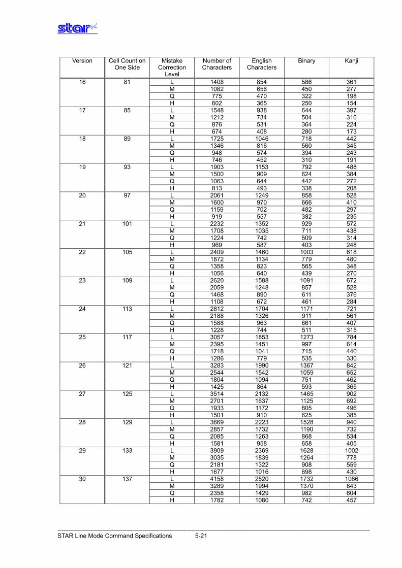
――――――――――――――――――――――――――――――――――――――――――――――――――――――――――――――――――――――――――――― STAR Line Mode Command Specifications 5-21
Version Cell Count on One Side
Mistake Correction
Level
Number of Characters
English Characters
Binary Kanji
16 81 L 1408 854 586 361 M 1082 656 450 277 Q 775 470 322 198 H 602 365 250 154
17 85 L 1548 938 644 397 M 1212 734 504 310 Q 876 531 364 224 H 674 408 280 173
18 89 L 1725 1046 718 442 M 1346 816 560 345 Q 948 574 394 243 H 746 452 310 191
19 93 L 1903 1153 792 488 M 1500 909 624 384 Q 1063 644 442 272 H 813 493 338 208
20 97 L 2061 1249 858 528 M 1600 970 666 410 Q 1159 702 482 297 H 919 557 382 235
21 101 L 2232 1352 929 572 M 1708 1035 711 438 Q 1224 742 509 314 H 969 587 403 248
22 105 L 2409 1460 1003 618 M 1872 1134 779 480 Q 1358 823 565 348 H 1056 640 439 270
23 109 L 2620 1588 1091 672 M 2059 1248 857 528 Q 1468 890 611 376 H 1108 672 461 284
24 113 L 2812 1704 1171 721 M 2188 1326 911 561 Q 1588 963 661 407 H 1228 744 511 315
25 117 L 3057 1853 1273 784 M 2395 1451 997 614 Q 1718 1041 715 440 H 1286 779 535 330
26 121 L 3283 1990 1367 842 M 2544 1542 1059 652 Q 1804 1094 751 462 H 1425 864 593 365
27 125 L 3514 2132 1465 902 M 2701 1637 1125 692 Q 1933 1172 805 496 H 1501 910 625 385
28 129 L 3669 2223 1528 940 M 2857 1732 1190 732 Q 2085 1263 868 534 H 1581 958 658 405
29 133 L 3909 2369 1628 1002 M 3035 1839 1264 778 Q 2181 1322 908 559 H 1677 1016 698 430
30 137 L 4158 2520 1732 1066 M 3289 1994 1370 843 Q 2358 1429 982 604 H 1782 1080 742 457
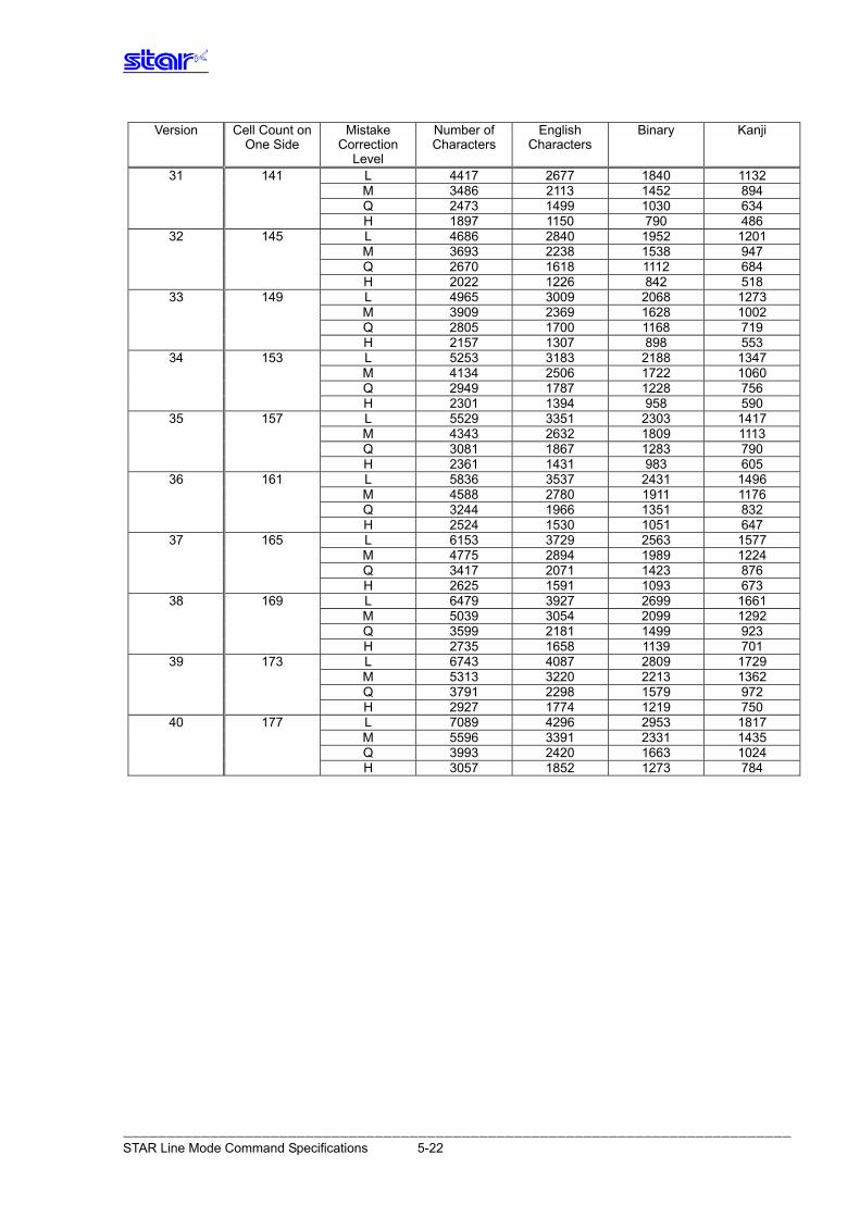
――――――――――――――――――――――――――――――――――――――――――――――――――――――――――――――――――――――――――――― STAR Line Mode Command Specifications 5-22
Version Cell Count on One Side
Mistake Correction
Level
Number of Characters
English Characters
Binary Kanji
31 141 L 4417 2677 1840 1132 M 3486 2113 1452 894 Q 2473 1499 1030 634 H 1897 1150 790 486
32 145 L 4686 2840 1952 1201 M 3693 2238 1538 947 Q 2670 1618 1112 684 H 2022 1226 842 518
33 149 L 4965 3009 2068 1273 M 3909 2369 1628 1002 Q 2805 1700 1168 719 H 2157 1307 898 553
34 153 L 5253 3183 2188 1347 M 4134 2506 1722 1060 Q 2949 1787 1228 756 H 2301 1394 958 590
35 157 L 5529 3351 2303 1417 M 4343 2632 1809 1113 Q 3081 1867 1283 790 H 2361 1431 983 605
36 161 L 5836 3537 2431 1496 M 4588 2780 1911 1176 Q 3244 1966 1351 832 H 2524 1530 1051 647
37 165 L 6153 3729 2563 1577 M 4775 2894 1989 1224 Q 3417 2071 1423 876 H 2625 1591 1093 673
38 169 L 6479 3927 2699 1661 M 5039 3054 2099 1292 Q 3599 2181 1499 923 H 2735 1658 1139 701
39 173 L 6743 4087 2809 1729 M 5313 3220 2213 1362 Q 3791 2298 1579 972 H 2927 1774 1219 750
40 177 L 7089 4296 2953 1817 M 5596 3391 2331 1435 Q 3993 2420 1663 1024 H 3057 1852 1273 784
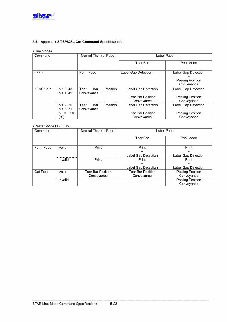
5.5. Appendix 8 TSP828L Cut Command Specifications <Line Mode>
Label Paper Command Normal Thermal Paper
Tear Bar Peel Mode
<FF> Form Feed Label Gap Detection Label Gap Detection +
Peeling Position Conveyance
n = 0, 48 n = 1, 49
Tear Bar Position Conveyance
Label Gap Detection +
Tear Bar Position Conveyance
Label Gap Detection +
Peeling Position Conveyance
<ESC> d n
n = 2, 50 Tear Bar Position Conveyance
Label Gap Detection Label Gap Detection n = 3, 51 + + n = 116 (“t”)
Tear Bar Position Conveyance
Peeling Position Conveyance
<Raster Mode FF/EOT>
Label Paper Command Normal Thermal Paper
Tear Bar Peel Mode
Valid Print Print +
Label Gap Detection
Print +
Label Gap Detection
Form Feed
Invalid Print Print Print + +
Label Gap Detection Label Gap Detection Valid Tear Bar Position
Conveyance Tear Bar Position
Conveyance Peeling Position
Conveyance Cut Feed
Invalid --- --- Peeling Position Conveyance
――――――――――――――――――――――――――――――――――――――――――――――――――――――――――――――――――――――――――――― STAR Line Mode Command Specifications 5-23
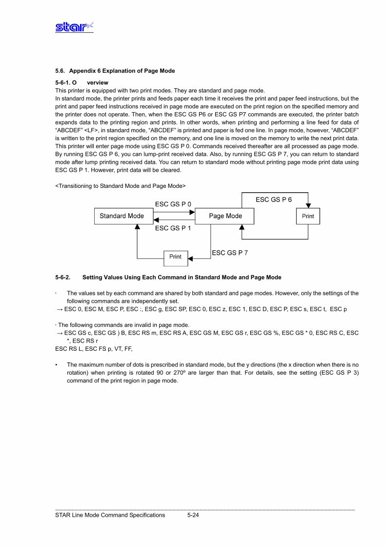
5.6. Appendix 6 Explanation of Page Mode
5-6-1. O verview This printer is equipped with two print modes. They are standard and page mode. In standard mode, the printer prints and feeds paper each time it receives the print and paper feed instructions, but the print and paper feed instructions received in page mode are executed on the print region on the specified memory and the printer does not operate. Then, when the ESC GS P6 or ESC GS P7 commands are executed, the printer batch expands data to the printing region and prints. In other words, when printing and performing a line feed for data of “ABCDEF” <LF>, in standard mode, “ABCDEF” is printed and paper is fed one line. In page mode, however, “ABCDEF” is written to the print region specified on the memory, and one line is moved on the memory to write the next print data. This printer will enter page mode using ESC GS P 0. Commands received thereafter are all processed as page mode. By running ESC GS P 6, you can lump-print received data. Also, by running ESC GS P 7, you can return to standard mode after lump printing received data. You can return to standard mode without printing page mode print data using ESC GS P 1. However, print data will be cleared. <Transitioning to Standard Mode and Page Mode>
5-6-2. Setting Values Using Each Command in Standard Mode and Page Mode • The values set by each command are shared by both standard and page modes. However, only the settings of the
following commands are independently set. → ESC 0, ESC M, ESC P, ESC :, ESC g, ESC SP, ESC 0, ESC z, ESC 1, ESC D, ESC P, ESC s, ESC t, ESC p • The following commands are invalid in page mode. → ESC GS c, ESC GS ) B, ESC RS m, ESC RS A, ESC GS M, ESC GS r, ESC GS %, ESC GS * 0, ESC RS C, ESC
*, ESC RS r ESC RS L, ESC FS p, VT, FF, • The maximum number of dots is prescribed in standard mode, but the y directions (the x direction when there is no
rotation) when printing is rotated 90 or 270º are larger than that. For details, see the setting (ESC GS P 3) command of the print region in page mode.
――――――――――――――――――――――――――――――――――――――――――――――――――――――――――――――――――――――――――――― STAR Line Mode Command Specifications 5-24
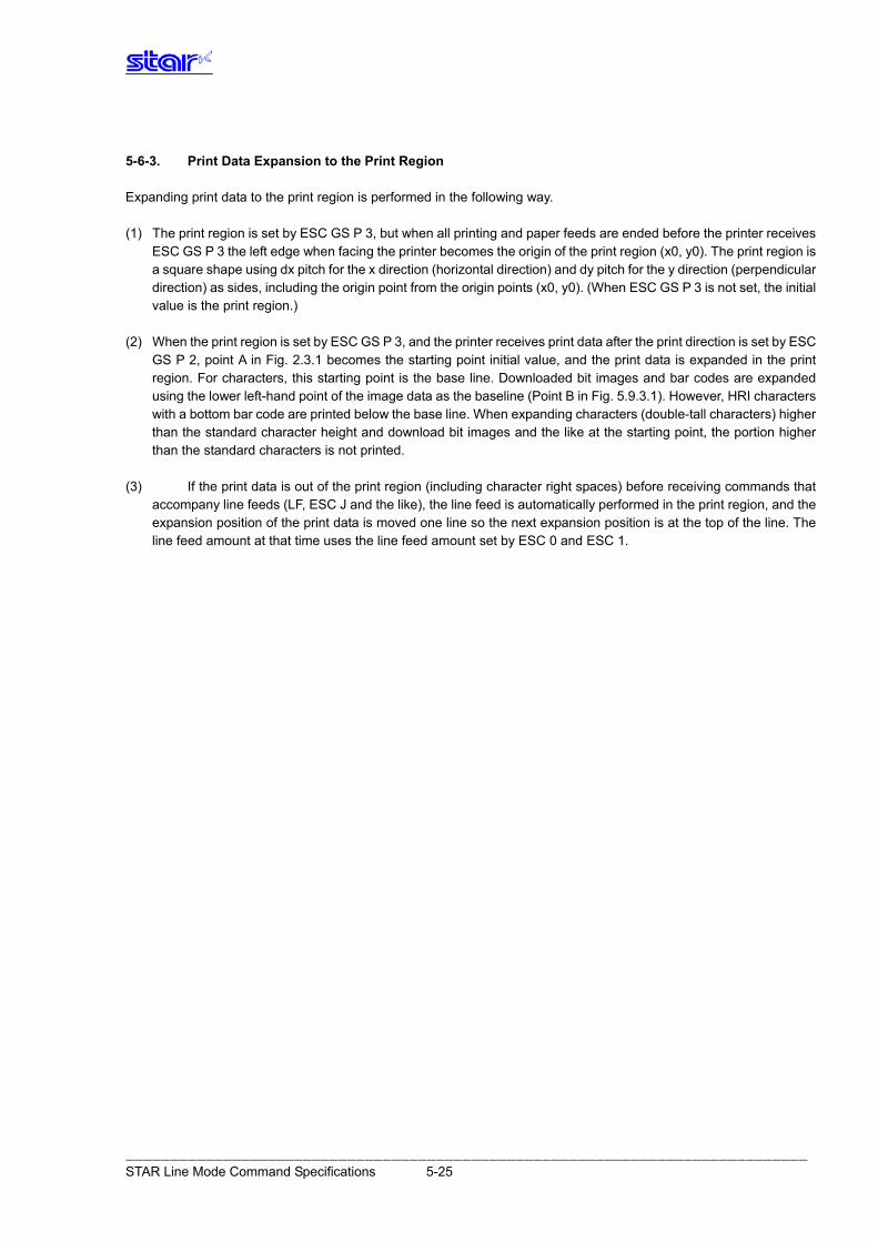
5-6-3. Print Data Expansion to the Print Region Expanding print data to the print region is performed in the following way. (1) The print region is set by ESC GS P 3, but when all printing and paper feeds are ended before the printer receives
ESC GS P 3 the left edge when facing the printer becomes the origin of the print region (x0, y0). The print region is a square shape using dx pitch for the x direction (horizontal direction) and dy pitch for the y direction (perpendicular direction) as sides, including the origin point from the origin points (x0, y0). (When ESC GS P 3 is not set, the initial value is the print region.)
(2) When the print region is set by ESC GS P 3, and the printer receives print data after the print direction is set by ESC
GS P 2, point A in Fig. 2.3.1 becomes the starting point initial value, and the print data is expanded in the print region. For characters, this starting point is the base line. Downloaded bit images and bar codes are expanded using the lower left-hand point of the image data as the baseline (Point B in Fig. 5.9.3.1). However, HRI characters with a bottom bar code are printed below the base line. When expanding characters (double-tall characters) higher than the standard character height and download bit images and the like at the starting point, the portion higher than the standard characters is not printed.
(3) If the print data is out of the print region (including character right spaces) before receiving commands that
accompany line feeds (LF, ESC J and the like), the line feed is automatically performed in the print region, and the expansion position of the print data is moved one line so the next expansion position is at the top of the line. The line feed amount at that time uses the line feed amount set by ESC 0 and ESC 1.
――――――――――――――――――――――――――――――――――――――――――――――――――――――――――――――――――――――――――――― STAR Line Mode Command Specifications 5-25
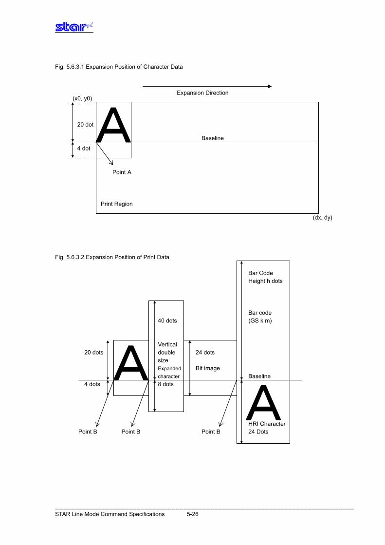
Fig. 5.6.3.1 Expansion Position of Character Data (x0, y0) Baseline A
Expansion Direction
(dx, dy) Fig. 5.6.3.2 Expansion Position of Print Data Bar Code Height h dots Bar code 40 dots (GS k m) Vertical 20 dots double 24 dots size Expanded Bit image character Baseline
4 dots 8 dots HRI Character
Point B Point B Point B 24 Dots
20 dot
4 dot
Point A
Print Region
AA
――――――――――――――――――――――――――――――――――――――――――――――――――――――――――――――――――――――――――――― STAR Line Mode Command Specifications 5-26
5.7. 5-7) Appendix 7 Explanation of Print Startup Control Starting Printing When Set to Page Units
When print startup control is set to page units, printing starts when the image buffer length is full or the following commands are run.
If the following commands are not received, start printing after a 1-second timeout. For details on image buffer length and how to set print startup control, see the product specifications manual.
Print starting trigger • Cutter command : <ESC> d n • FF command : <FF> • BM detection command : <ESC> d n, <FF> • Print startup command : <ESC><GS> g 0 m n • Raster mode : <ESC> <FF> <NUL> : <ESC> <FF> <EOT>
――――――――――――――――――――――――――――――――――――――――――――――――――――――――――――――――――――――――――――― STAR Line Mode Command Specifications 5-27
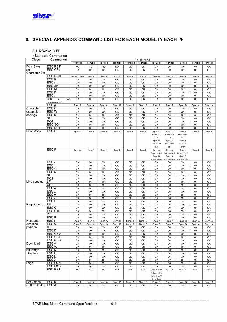
――――――――――――――――――――――――――――――――――――――――――――――――――――――――――――――――――――――――――――― STAR Line Mode Command Specifications 6-1
6. SPECIAL APPENDIX COMMAND LIST FOR EACH MODEL IN EACH I/F
6.1. RS-232 C I/F • Standard Commands Class Commands Model Name
TSP800 TSP700 TSP600 TUP900 TSP1000 TSP828L TSP700II TSP650 TUP500 TSP800II FVP10Font Style ESC RS F NO NO NO NO OK OK OK OK OK OK OK and Character Set
ESC GS t OK OK OK OK OK OK OK OK OK OK OK
ESC GS = Ver. 3.0 or later Spec. A Spec. A Spec. A Spec. A Spec. A Spec. B Spec. B Spec. B Spec. B Spec. B
ESC R OK OK OK OK OK OK OK OK OK OK OK ESC / OK OK OK OK OK OK OK OK OK OK OK ESC SP OK OK OK OK OK OK OK OK OK OK OK ESC M OK OK OK OK OK OK OK OK OK OK OK ESC P OK OK OK OK OK OK OK OK OK OK OK ESC : OK OK OK OK OK OK OK OK OK OK OK ESC p (Not
recommended) OK OK OK OK OK OK OK OK OK OK OK
ESC g Spec. A Spec. A Spec. A Spec. B Spec. B Spec. B Spec. A Spec. A Spec. B Spec. A Spec. A Character ESC i OK OK OK OK OK OK OK OK OK OK OK expansion ESC W OK OK OK OK OK OK OK OK OK OK OK settings ESC h OK OK OK OK OK OK OK OK OK OK OK SO OK OK OK OK OK OK OK OK OK OK OK DC4 OK OK OK OK OK OK OK OK OK OK OK ESC SO OK OK OK OK OK OK OK OK OK OK OK ESC DC4 OK OK OK OK OK OK OK OK OK OK OK Print Mode ESC E Spec. A Spec. A Spec. A Spec. B Spec. B Spec. B Spec. A
Before Ver. 2.0
Spec. B Ver. 2.0 or
later
Spec. A Before Ver.
2.0 Spec. B
Ver. 2.0 or later
Spec. A Before Ver.
2.0 Spec. B
Ver. 2.0 or later
Spec. B Spec. B
ESC F Spec. A Spec. A Spec. A Spec. B Spec. B Spec. B Spec. A Before V. 2.0
Spec. B V. 2.0 or later
Spec. A Before V. 2.0
Spec. B V. 2.0 or later
Spec. A Before V. 2.0
Spec. B V. 2.0 or later
Spec. B Spec. B
ESC - OK OK OK OK OK OK OK OK OK OK OK ESC _ OK OK OK OK OK OK OK OK OK OK OK ESC 4 OK OK OK OK OK OK OK OK OK OK OK ESC 5 OK OK OK OK OK OK OK OK OK OK OK SI OK OK OK OK OK OK OK OK OK OK OK DC2 OK OK OK OK OK OK OK OK OK OK OK Line spacing LF OK OK OK OK OK OK OK OK OK OK OK CR OK OK OK OK OK OK OK OK OK OK OK ESC a OK OK OK OK OK OK OK OK OK OK OK ESC z OK OK OK OK OK OK OK OK OK OK OK ESC 0 OK OK OK OK OK OK OK OK OK OK OK ESC J OK OK OK OK OK OK OK OK OK OK OK ESC I OK OK OK OK OK OK OK OK OK OK OK Page Control FF OK OK OK OK OK OK OK OK OK OK OK
ESC C OK OK OK OK OK OK OK OK OK OK OK ESC C 0 OK OK OK OK OK OK OK OK OK OK OK VT OK OK OK OK OK OK OK OK OK OK OK ESC B OK OK OK OK OK OK OK OK OK OK OK Horizontal ESC l Spec. A Spec. A Spec. A Spec. B Spec. B Spec. B Spec. A Spec. A Spec. B Spec. A Spec. A direction ESC Q Spec. A Spec. A Spec. A Spec. B Spec. B Spec. B Spec. A Spec. A Spec. B Spec. A Spec. A position HT OK OK OK OK OK OK OK OK OK OK OK ESC D OK OK OK OK OK OK OK OK OK OK OK ESC GS A OK OK OK OK OK OK OK OK OK OK OK ESC GS R OK OK OK OK OK OK OK OK OK OK OK ESC GS a OK OK OK OK OK OK OK OK OK OK OK Download ESC & OK OK OK OK OK OK OK OK OK OK OK ESC % OK OK OK OK OK OK OK OK OK OK OK Bit Image ESC K OK OK OK OK OK OK OK OK OK OK OK Graphics ESC L OK OK OK OK OK OK OK OK OK OK OK ESC k OK OK OK OK OK OK OK OK OK OK OK ESC X OK OK OK OK OK OK OK OK OK OK OK Logo ESC FS q OK OK OK OK OK OK OK OK OK OK OK ESC FS p OK OK OK OK OK OK OK OK OK OK OK ESC RS L NO NO NO NO NO NO Spec. A for V.
1.2 or earier; Spec. B for V.
1.3 or later
Spec. B Spec. B Spec. B Spec. B
Bar Codes ESC b Spec. A Spec. A Spec. A Spec. B Spec. B Spec. B Spec. B Spec. B Spec. B Spec. B Spec. BCutter Control ESC d OK OK OK OK OK OK OK OK OK OK OK
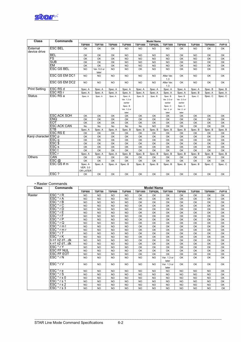
――――――――――――――――――――――――――――――――――――――――――――――――――――――――――――――――――――――――――――― STAR Line Mode Command Specifications 6-2
Class Commands Model Name
TSP800 TSP700 TSP600 TUP900 TSP1000 TSP828L TSP700II TSP650 TUP500 TSP800II FVP10External device drive
ESC BEL OK OK OK NO NO NO NO OK NO OK OK
BEL OK OK OK NO NO NO NO OK NO OK OK FS OK OK OK NO NO NO NO OK NO OK OK SUB OK OK OK NO NO NO NO OK NO OK OK EM OK OK OK NO NO NO NO OK NO OK OK ESC GS BEL NO Ver. 5.0 or
later NO NO OK NO NO OK NO OK OK
ESC GS EM DC1 NO NO NO NO NO NO After Ver. 1.3
OK NO OK OK
ESC GS EM DC2 NO NO NO NO NO NO After Ver. 1.3
OK NO OK OK
Print Setting ESC RS d Spec. A Spec. A Spec. A Spec. A Spec. A Spec. A Spec. A Spec. A Spec. A Spec. B Spec. B ESC RS r Spec. A Spec. A Spec. A Spec. A Spec. A Spec. A Spec. A Spec. A Spec. B Spec. A Spec. AStatus ESC RS a Spec. A Spec. A Spec. A
Spec. A
Ver. 1.2 or earlier
Spec. B Ver. 1.2 or
later
Spec. B Spec. B Spec. B Ver. 2.0 or
earlier Spec. C Ver. 2. or
later
Spec. B Ver. 2.0 or
earlier Spec. C Ver. 2. or
later
Spec. C Spec. C Spec. C
ESC ACK SOH OK OK OK OK OK OK OK OK OK OK OK ENQ OK OK OK OK OK OK OK OK OK OK OK EOT OK OK OK OK OK OK OK OK OK OK OK ESC ACK CAN No No No No No NO OK OK OK OK OK ETB Spec. A Spec. A Spec. A Spec. B Spec. B Spec. B Spec. B Spec. B Spec. B Spec. B Spec. B ESC RS E OK OK OK OK OK OK OK OK OK OK OK Kanji character ESC p OK OK OK OK OK OK OK OK OK OK OK ESC q OK OK OK OK OK OK OK OK OK OK OK ESC $ OK OK OK OK OK OK OK OK OK OK OK ESC s OK OK OK OK OK OK OK OK OK OK OK ESC t OK OK OK OK OK OK OK OK OK OK OK ESC r Spec. A Spec. A Spec. A Spec. B Spec. B Spec. B Spec. B Spec. B Spec. B Spec. B Spec. BOthers CAN OK OK OK OK OK OK OK OK OK OK OK ESC @ OK OK OK OK OK OK OK OK OK OK OK ESC GS # m Spec. A
VER. 3.0 OR LATER
Spec. A Spec. A Spec. B Spec. B Spec. B Spec. B Spec. B Spec. B Spec. C Spec. C
ESC ? OK OK OK OK OK OK OK OK OK OK OK
• Raster Commands Class Commands Model Name
TSP800 TSP700 TSP600 TUP900 TSP1000 TSP828L TSP700II TSP650 TUP500 TSP800II FVP10Raster ESC * r R NO NO NO NO OK OK OK OK OK OK OK ESC * r A NO NO NO NO OK OK OK OK OK OK OK ESC * r B NO NO NO NO OK OK OK OK OK OK OK ESC * r C NO NO NO NO OK OK OK OK OK OK OK ESC * r D NO NO NO NO OK OK OK OK OK OK OK ESC * r E NO NO NO NO OK OK OK OK OK OK OK ESC * r F NO NO NO NO OK OK OK OK OK OK OK ESC * r P NO NO NO NO OK OK OK OK OK OK OK ESC * r Q NO NO NO NO OK OK OK OK OK OK OK ESC * r m l NO NO NO NO OK OK OK OK OK OK OK ESC * r m r NO NO NO NO OK OK OK OK OK OK OK ESC * r T NO NO NO NO OK OK OK OK OK OK OK ESC * r K NO NO NO NO OK OK OK OK OK OK OK b n1 n2 d1...dk NO NO NO NO OK OK OK OK OK OK OK k n1 n2 d1...dk NO NO NO NO OK OK OK OK OK OK OK ESC * r Y NO NO NO NO OK OK OK OK OK OK OK ESC FF NUL NO NO NO NO OK OK OK OK OK OK OK ESC FF EOT NO NO NO NO OK OK OK OK OK OK OK ESC * r N NO NO NO NO NO NO Ver. 1.3 or
later OK OK OK OK
ESC * r V NO NO NO NO NO NO Ver. 1.3 or later
OK OK OK OK
ESC * r e NO NO NO NO NO NO NO NO NO NO OK ESC * r S NO NO NO NO NO NO NO NO NO NO OK ESC * r s 0 NO NO NO NO NO NO NO NO NO NO OK ESC * r s 1 NO NO NO NO NO NO NO NO NO NO OK ESC * r s 2 NO NO NO NO NO NO NO NO NO NO OK ESC * r s 3 NO NO NO NO NO NO NO NO NO NO OK
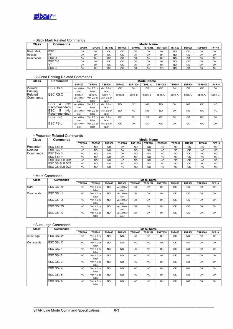
――――――――――――――――――――――――――――――――――――――――――――――――――――――――――――――――――――――――――――― STAR Line Mode Command Specifications 6-3
• Black Mark Related Commands Class Commands Model Name
TSP800 TSP700 TSP600 TUP900 TSP1000 TSP828L TSP700II TSP650 TUP500 TSP800II FVP10Black Mark ESC d OK OK OK OK OK OK OK NO OK OK OK Related FF OK OK OK OK OK OK OK NO OK OK OK Commands ESC C OK OK OK OK OK OK OK NO OK OK OK ESC C 0 OK OK OK OK OK OK OK NO OK OK OK VT OK OK OK OK OK OK OK NO OK OK OK ESC B OK OK OK OK OK OK NO NO OK OK OK
• 2-Color Printing Related Commands Class Commands Model Name
TSP800 TSP700 TSP600 TUP900 TSP1000 TSP828L TSP700II TSP650 TUP500 TSP800II FVP102-Color Printing
ESC RS c Ver. 4.0 or later
Ver. 2.0 or later
Ver. 2.0 or later
OK OK OK OK OK OK OK OK
Related Commands
ESC RS C Spec. A Ver. 4.0 or
later
Spec. A Ver. 2.0 or
later
Spec. A Ver. 2.0 or
later
Spec. B Spec. B Spec. B Spec. C Spec. A Spec. C Spec. C Spec. C
ESC 4 (Not Recommended)
Ver. 4.0 or later
Ver. 2.0 or later
Ver. 2.0 or later
NO NO NO NO OK NO OK NO
ESC 5 (Not Recommended)
Ver. 4.0 or later
Ver. 2.0 or later
Ver. 2.0 or later
NO NO NO NO OK NO OK NO
ESC FS q Ver. 4.0 or later
Ver. 2.0 or later
Ver. 2.0 or later
OK OK OK OK OK OK OK OK
ESC FS p Ver. 4.0 or later
Ver. 2.0 or later
Ver. 2.0 or later
OK OK OK OK OK OK OK OK
• Presenter Related Commands Class Commands Model Name
TSP800 TSP700 TSP600 TUP900 TSP1000 TSP828L TSP700II TSP650 TUP500 TP800II FVP10Presenter ESC SYN 0 NO NO NO OK NO NO NO NO OK NO NO Related ESC SYN 1 NO NO NO OK NO NO NO NO OK NO NO Commands ESC SYN 3 NO NO NO OK NO NO NO NO OK NO NO ESC SYN 4 NO NO NO OK NO NO NO NO OK NO NO ESC GS SUB DC1 NO NO NO NO NO NO NO NO OK NO NO ESC GS SUB DC2 NO NO NO NO NO NO NO NO OK NO NO ESC GS SUB DC3 NO NO NO NO NO NO NO NO OK NO NO
• Mark Commands Class Commands Model Name
TSP800 TSP700 TSP600 TUP900 TSP1000 TSP828L TSP700II TSP650 TUP500 TSP800II FVP10Mark ESC GS * 0 NO Ver. 4.0 or
later NO Ver. 3.0 or
later OK OK OK OK OK OK OK
Commands ESC GS * 1 NO Ver. 4.0 or later
NO Ver. 3.0 or later
OK OK OK OK OK OK OK
ESC GS * 2 NO Ver. 4.0 or later
NO Ver. 3.0 or later
OK OK OK OK OK OK OK
ESC GS * W NO Ver. 4.0 or later
NO Ver. 3.0 or later
OK OK OK OK OK OK OK
ESC GS * C NO Ver. 4.0 or later
NO Ver. 3.0 or later
OK OK OK OK OK OK OK
• Auto Logo Commands Class Commands Model Name
TSP800 TSP700 TSP600 TUP900 TSP1000 TSP828L TSP700II TSP650 TUP500 TSP800II FVP10Auto Logo ESC GS / W NO Ver. 4.0 or
later NO NO NO NO OK OK NO OK OK
Commands ESC GS / C NO Ver. 4.0 or later
NO NO NO NO OK OK NO OK OK
ESC GS / 1 NO Ver. 4.0 or later
NO NO NO NO OK OK NO OK OK
ESC GS / 2 NO Ver. 4.0 or later
NO NO NO NO OK OK NO OK OK
ESC GS / 3 NO Ver. 4.0 or later
NO NO NO NO OK OK NO OK OK
ESC GS / 4 NO Ver. 4.0 or later
NO NO NO NO OK OK NO OK OK
ESC GS / 5 NO Ver. 4.0 or later
NO NO NO NO OK OK NO OK OK
ESC GS / 6 NO Ver. 4.0 or later
NO NO NO NO OK OK NO OK OK
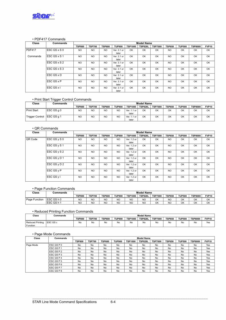
――――――――――――――――――――――――――――――――――――――――――――――――――――――――――――――――――――――――――――― STAR Line Mode Command Specifications 6-4
• PDF417 Commands Class Commands Model Name
TSP800 TSP700 TSP600 TUP900 TSP1000 TSP828L TSP700II TSP650 TUP500 TSP800II FVP10PDF417 ESC GS x S 0 NO NO NO Ver. 3.1 or
later OK OK OK NO OK OK OK
Commands ESC GS x S 1 NO NO NO Ver. 3.1 or later
OK OK OK NO OK OK OK
ESC GS x S 2 NO NO NO Ver. 3.1 or later
OK OK OK NO OK OK OK
ESC GS x S 3 NO NO NO Ver. 3.1 or later
OK OK OK NO OK OK OK
ESC GS x D NO NO NO Ver. 3.1 or later
OK OK OK NO OK OK OK
ESC GS x P NO NO NO Ver. 3.1 or later
OK OK OK NO OK OK OK
ESC GS x I NO NO NO Ver. 3.1 or later
OK OK OK NO OK OK OK
• Print Start Trigger Control Commands Class Commands Model Name
TSP800 TSP700 TSP600 TUP900 TSP1000 TSP828L TSP700II TSP650 TUP500 TSP800II FVP10Print Start ESC GS g 0 NO NO NO NO Ver. 1.1 or
later OK OK OK OK OK OK
Trigger Control ESC GS g 1 NO NO NO NO Ver. 1.1 or later
OK OK OK OK OK OK
• QR Commands Class Commands Model Name
TSP800 TSP700 TSP600 TUP900 TSP1000 TSP828L TSP700II TSP650 TUP500 TSP800II FVP10QR Code ESC GS y S 0 NO NO NO NO Ver. 1.2 or
later OK OK NO OK OK OK
ESC GS y S 1 NO NO NO NO Ver. 1.2 or later
OK OK NO OK OK OK
ESC GS y S 2 NO NO NO NO Ver. 1.2 or later
OK OK NO OK OK OK
ESC GS y D 1 NO NO NO NO Ver. 1.2 or later
OK OK NO OK OK OK
ESC GS y D 2 NO NO NO NO Ver. 1.2 or later
OK OK NO OK OK OK
ESC GS y P NO NO NO NO Ver. 1.2 or later
OK OK NO OK OK OK
ESC GS y I NO NO NO NO Ver. 1.2 or later
OK OK NO OK OK OK
• Page Function Commands Class Commands Model Name
TSP800 TSP700 TSP600 TUP900 TSP1000 TSP828L TSP700II TSP650 TUP500 TSP800II FVP10Page Function ESC GS h 0 NO NO NO NO NO NO OK NO OK OK OK ESC GS h 1 NO NO NO NO NO NO OK NO OK OK OK
• Reduced Printing Function Commands Class Commands Model Name
TSP800 TSP700 TSP600 TUP900 TSP1000 TSP828L TSP700II TSP650 TUP500 TSP800II FVP10Reduced Printing Function
ESC GS c No No No No No No No No No No Yes
• Page Mode Commands Class Commands Model Name
TSP800 TSP700 TSP600 TUP900 TSP1000 TSP828L TSP700II TSP650 TUP500 TSP800II FVP10Page Mode ESC GS P 0 No No No No No No No No No No Yes ESC GS P 1 No No No No No No No No No No Yes ESC GS P 2 No No No No No No No No No No Yes ESC GS P 3 No No No No No No No No No No Yes ESC GS P 4 No No No No No No No No No No Yes ESC GS P 5 No No No No No No No No No No Yes ESC GS P 6 No No No No No No No No No No Yes ESC GS P 7 No No No No No No No No No No Yes ESC GS P 8 No No No No No No No No No No Yes

• Text Search Commands
Class Commands Model Name TSP800 TSP700II TSP650 TUP500 TSP700 TSP600 TUP900 TSP1000 TSP828L TSP800II FVP10
Text Search ESC GS ) B (fn = 48) No No No No No No No No No No Yes ESC GS ) B (fn = 49) No No No No No No No No No No Yes
ESC GS ) B (fn = 50) No No No No No No No No No No Yes
ESC GS ) B (fn = 64) No No No No No No No No No No Yes
ESC GS ) B (fn = 65) No No No No No No No No No No Yes
ESC GS ) B (fn = 80) No No No No No No No No No No Yes
ESC GS ) B (fn = 81) No No No No No No No No No No Yes
ESC GS ) B (fn = 96) No No No No No No No No No No Yes
ESC GS ) B (fn = 97) No No No No No No No No No No Yes
• Audio Commands
Class Commands Model Name TSP800 TSP700II TSP650 TUP500 TSP700 TSP600 TUP900 TSP1000 TSP828L TSP800II FVP10
Audio ESC GS s O No No No No No No No No No No Yes ESC GS s P No No No No No No No No No No Yes
ESC GS s R No No No No No No No No No No Yes
ESC GS s I No No No No No No No No No No Yes
ESC GS s U No No No No No No No No No No Yes
ESC GS s T No No No No No No No No No No Yes
――――――――――――――――――――――――――――――――――――――――――――――――――――――――――――――――――――――――――――― STAR Line Mode Command Specifications 6-5
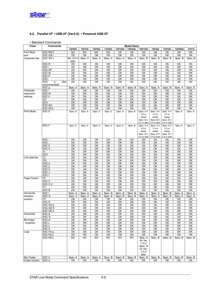
――――――――――――――――――――――――――――――――――――――――――――――――――――――――――――――――――――――――――――― STAR Line Mode Command Specifications 6-6
6.2. Parallel I/F • USB I/F (Ver2.0) • Powered USB I/F • Standard Commands Class Commands Model Name
TSP800 TSP700 TSP600 TUP900 TSP1000 TSP828L TSP700II TSP650 TUP500 TSP800II FVP10Font Style ESC RS F NO NO NO NO OK OK OK OK OK OK OK and ESC GS t OK OK OK OK OK OK OK OK OK OK OK Character Set ESC GS = Ver. 3.0 or
later Spec. A Spec. A Spec. A Spec. A Spec. A Spec. B Spec. B Spec. B Spec. B Spec. B
ESC R OK OK OK OK OK OK OK OK OK OK OK ESC / OK OK OK OK OK OK OK OK OK OK OK ESC SP OK OK OK OK OK OK OK OK OK OK OK ESC M OK OK OK OK OK OK OK OK OK OK OK ESC P OK OK OK OK OK OK OK OK OK OK OK ESC : OK OK OK OK OK OK OK OK OK OK OK ESC p (Not
recommended) OK OK OK OK OK OK OK OK OK OK OK
ESC g Spec. A Spec. A Spec. A Spec. B Spec. B Spec. B Spec. A Spec. A Spec. B Spec. A Spec. ACharacter ESC i OK OK OK OK OK OK OK OK OK OK OK expansion ESC W OK OK OK OK OK OK OK OK OK OK OK settings ESC h OK OK OK OK OK OK OK OK OK OK OK SO OK OK OK OK OK OK OK OK OK OK OK DC4 OK OK OK OK OK OK OK OK OK OK OK ESC SO OK OK OK OK OK OK OK OK OK OK OK ESC DC4 OK OK OK OK OK OK OK OK OK OK OK Print Mode ESC E Spec. A Spec. A Spec. A Spec. A Spec. A Spec. B Spec. A V.
2.0 or earlier
Spec. B V. 2.0 or later
Spec. A V. 2.0 or earlier
Spec. B V. 2.0 or later
Spec. A V. 2.0 or earlier
Spec. B V. 2.0 or later
Spec. A Spec. A
ESC F Spec. A Spec. A Spec. A Spec. A Spec. A Spec. B Spec. A V. 2.0 or earlier
Spec. B V. 2.0 or later
Spec. A V. 2.0 or earlier
Spec. B V. 2.0 or later
Spec. A V. 2.0 or earlier
Spec. B V. 2.0 or later
Spec. A Spec. A
ESC - OK OK OK OK OK OK OK OK OK OK OK ESC _ OK OK OK OK OK OK OK OK OK OK OK ESC 4 OK OK OK OK OK OK OK OK OK OK OK ESC 5 OK OK OK OK OK OK OK OK OK OK OK SI OK OK OK OK OK OK OK OK OK OK OK DC2 OK OK OK OK OK OK OK OK OK OK OK Line spacing LF OK OK OK OK OK OK OK OK OK OK OK CR OK OK OK OK OK OK OK OK OK OK OK ESC a OK OK OK OK OK OK OK OK OK OK OK ESC z OK OK OK OK OK OK OK OK OK OK OK ESC 0 OK OK OK OK OK OK OK OK OK OK OK ESC J OK OK OK OK OK OK OK OK OK OK OK ESC I OK OK OK OK OK OK OK OK OK OK OK Page Control FF OK OK OK OK OK OK OK OK OK OK OK
ESC C OK OK OK OK OK OK OK OK OK OK OK ESC C 0 OK OK OK OK OK OK OK OK OK OK OK VT OK OK OK OK OK OK OK OK OK OK OK
ESC B OK OK OK OK OK OK OK OK OK OK OK Horizontal ESC l Spec. A Spec. A Spec. A Spec. B Spec. B Spec. B Spec. A Spec. A Spec. B Spec. A Spec. Adirection ESC Q Spec. A Spec. A Spec. A Spec. B Spec. B Spec. B Spec. A Spec. A Spec. B Spec. A Spec. Aposition HT OK OK OK OK OK OK OK OK OK OK OK ESC D OK OK OK OK OK OK OK OK OK OK OK ESC GS A OK OK OK OK OK OK OK OK OK OK OK ESC GS R OK OK OK OK OK OK OK OK OK OK OK ESC GS a OK OK OK OK OK OK OK OK OK OK OK Download ESC & OK OK OK OK OK OK OK OK OK OK OK ESC % OK OK OK OK OK OK OK OK OK OK OK Bit Image ESC K OK OK OK OK OK OK OK OK OK OK OK Graphics ESC L OK OK OK OK OK OK OK OK OK OK OK
ESC k OK OK OK OK OK OK OK OK OK OK OK ESC X OK OK OK OK OK OK OK OK OK OK OK Logo ESC FS q OK OK OK OK OK OK OK OK OK OK OK ESC FS p OK OK OK OK OK OK OK OK OK OK OK ESC RS L NO NO NO NO NO NO Spec. A
for Ver. 1.2 or
Spec. B for Ver. 1.3 or later.
Spec. B Spec. B Spec. B Spec. B
Bar Codes ESC b Spec. A Spec. A Spec. A Spec. B Spec. B Spec. B Spec. B Spec. B Spec. B Spec. B Spec. BCutter Control ESC d OK OK OK OK OK OK OK OK OK OK OK
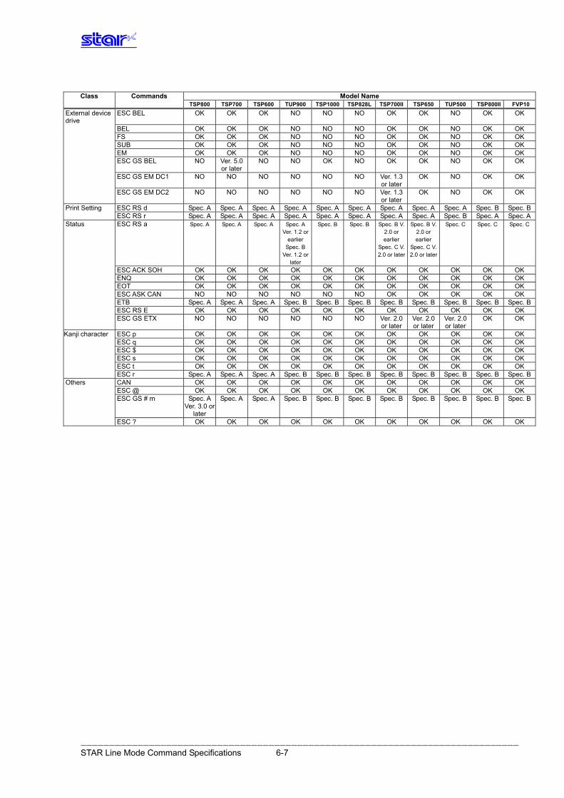
――――――――――――――――――――――――――――――――――――――――――――――――――――――――――――――――――――――――――――― STAR Line Mode Command Specifications 6-7
Class Commands Model Name
TSP800 TSP700 TSP600 TUP900 TSP1000 TSP828L TSP700II TSP650 TUP500 TSP800II FVP10External device drive
ESC BEL OK OK OK NO NO NO OK OK NO OK OK
BEL OK OK OK NO NO NO OK OK NO OK OK FS OK OK OK NO NO NO OK OK NO OK OK SUB OK OK OK NO NO NO OK OK NO OK OK EM OK OK OK NO NO NO OK OK NO OK OK ESC GS BEL NO Ver. 5.0
or laterNO NO OK NO OK OK NO OK OK
ESC GS EM DC1 NO NO NO NO NO NO Ver. 1.3 or later
OK NO OK OK
ESC GS EM DC2 NO NO NO NO NO NO Ver. 1.3 or later
OK NO OK OK
Print Setting ESC RS d Spec. A Spec. A Spec. A Spec. A Spec. A Spec. A Spec. A Spec. A Spec. A Spec. B Spec. B ESC RS r Spec. A Spec. A Spec. A Spec. A Spec. A Spec. A Spec. A Spec. A Spec. B Spec. A Spec. AStatus ESC RS a Spec. A Spec. A Spec. A
Spec. A
Ver. 1.2 or earlier
Spec. BVer. 1.2 or
later
Spec. B Spec. B Spec. B V. 2.0 or earlier
Spec. C V. 2.0 or later
Spec. B V. 2.0 or earlier
Spec. C V. 2.0 or later
Spec. C Spec. C Spec. C
ESC ACK SOH OK OK OK OK OK OK OK OK OK OK OK ENQ OK OK OK OK OK OK OK OK OK OK OK EOT OK OK OK OK OK OK OK OK OK OK OK ESC ASK CAN NO NO NO NO NO NO OK OK OK OK OK ETB Spec. A Spec. A Spec. A Spec. B Spec. B Spec. B Spec. B Spec. B Spec. B Spec. B Spec. B ESC RS E OK OK OK OK OK OK OK OK OK OK OK ESC GS ETX NO NO NO NO NO NO Ver. 2.0
or later Ver. 2.0 or later
Ver. 2.0 or later
OK OK
Kanji character ESC p OK OK OK OK OK OK OK OK OK OK OK ESC q OK OK OK OK OK OK OK OK OK OK OK ESC $ OK OK OK OK OK OK OK OK OK OK OK ESC s OK OK OK OK OK OK OK OK OK OK OK ESC t OK OK OK OK OK OK OK OK OK OK OK ESC r Spec. A Spec. A Spec. A Spec. B Spec. B Spec. B Spec. B Spec. B Spec. B Spec. B Spec. BOthers CAN OK OK OK OK OK OK OK OK OK OK OK ESC @ OK OK OK OK OK OK OK OK OK OK OK ESC GS # m Spec. A
Ver. 3.0 or later
Spec. A Spec. A Spec. B Spec. B Spec. B Spec. B Spec. B Spec. B Spec. B Spec. B
ESC ? OK OK OK OK OK OK OK OK OK OK OK
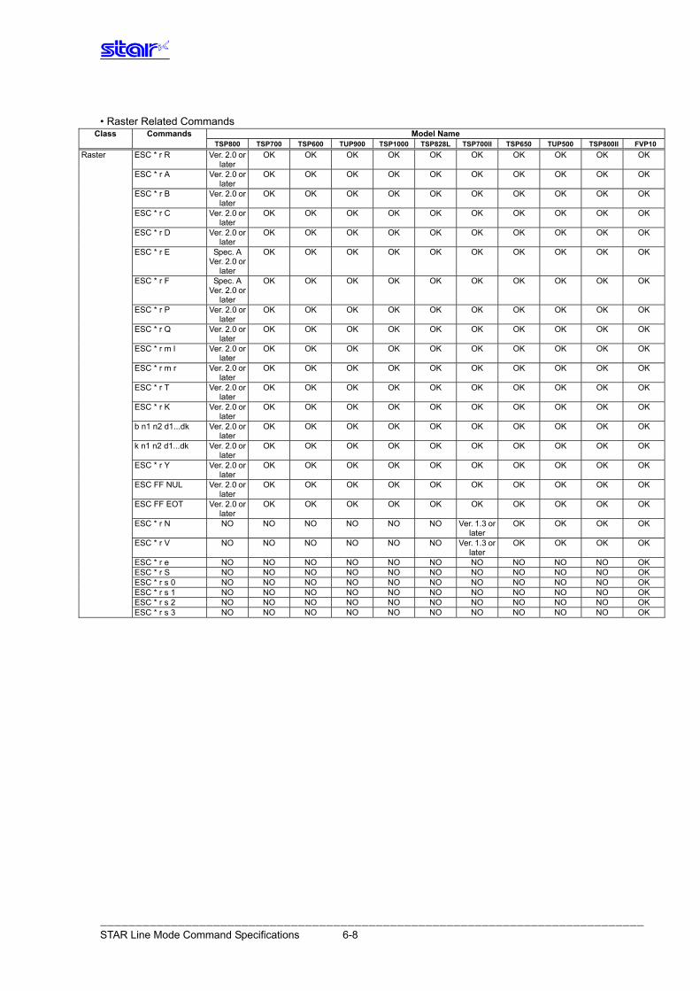
――――――――――――――――――――――――――――――――――――――――――――――――――――――――――――――――――――――――――――― STAR Line Mode Command Specifications 6-8
• Raster Related Commands
Class Commands Model Name TSP800 TSP700 TSP600 TUP900 TSP1000 TSP828L TSP700II TSP650 TUP500 TSP800II FVP10 Raster ESC * r R Ver. 2.0 or
later OK OK OK OK OK OK OK OK OK OK
ESC * r A Ver. 2.0 or later
OK OK OK OK OK OK OK OK OK OK
ESC * r B Ver. 2.0 or later
OK OK OK OK OK OK OK OK OK OK
ESC * r C Ver. 2.0 or later
OK OK OK OK OK OK OK OK OK OK
ESC * r D Ver. 2.0 or later
OK OK OK OK OK OK OK OK OK OK
ESC * r E Spec. A Ver. 2.0 or
later
OK OK OK OK OK OK OK OK OK OK
ESC * r F Spec. A Ver. 2.0 or
later
OK OK OK OK OK OK OK OK OK OK
ESC * r P Ver. 2.0 or later
OK OK OK OK OK OK OK OK OK OK
ESC * r Q Ver. 2.0 or later
OK OK OK OK OK OK OK OK OK OK
ESC * r m l Ver. 2.0 or later
OK OK OK OK OK OK OK OK OK OK
ESC * r m r Ver. 2.0 or later
OK OK OK OK OK OK OK OK OK OK
ESC * r T Ver. 2.0 or later
OK OK OK OK OK OK OK OK OK OK
ESC * r K Ver. 2.0 or later
OK OK OK OK OK OK OK OK OK OK
b n1 n2 d1...dk Ver. 2.0 or later
OK OK OK OK OK OK OK OK OK OK
k n1 n2 d1...dk Ver. 2.0 or later
OK OK OK OK OK OK OK OK OK OK
ESC * r Y Ver. 2.0 or later
OK OK OK OK OK OK OK OK OK OK
ESC FF NUL Ver. 2.0 or later
OK OK OK OK OK OK OK OK OK OK
ESC FF EOT Ver. 2.0 or later
OK OK OK OK OK OK OK OK OK OK
ESC * r N NO NO NO NO NO NO Ver. 1.3 or later
OK OK OK OK
ESC * r V NO NO NO NO NO NO Ver. 1.3 or later
OK OK OK OK
ESC * r e NO NO NO NO NO NO NO NO NO NO OK ESC * r S NO NO NO NO NO NO NO NO NO NO OK ESC * r s 0 NO NO NO NO NO NO NO NO NO NO OK ESC * r s 1 NO NO NO NO NO NO NO NO NO NO OK ESC * r s 2 NO NO NO NO NO NO NO NO NO NO OK ESC * r s 3 NO NO NO NO NO NO NO NO NO NO OK
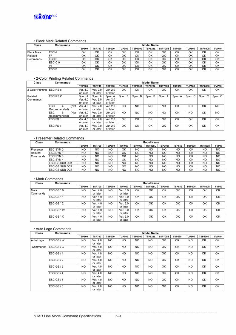
――――――――――――――――――――――――――――――――――――――――――――――――――――――――――――――――――――――――――――― STAR Line Mode Command Specifications 6-9
• Black Mark Related Commands Class Commands Model Name
TSP800 TSP700 TSP600 TUP900 TSP1000 TSP828L TSP700II TSP650 TUP500 TSP800II FVP10Black Mark ESC d OK OK OK OK OK OK OK OK OK OK OK Related FF OK OK OK OK OK OK OK OK OK OK OK Commands ESC C OK OK OK OK OK OK OK OK OK OK OK ESC C 0 OK OK OK OK OK OK OK OK OK OK OK VT OK OK OK OK OK OK OK OK OK OK OK ESC B OK OK OK OK OK OK OK OK OK OK OK
• 2-Color Printing Related Commands Class Commands Model Name
TSP800 TSP700 TSP600 TUP900 TSP1000 TSP828L TSP700II TSP650 TUP500 TSP800II FVP102-Color Printing ESC RS c Ver. 4.0
or later Ver. 2.0 or later
Ver. 2.0 or later
OK OK OK OK OK OK OK OK
Related Commands
ESC RS C Spec. A Ver. 4.0 or later
Spec. AVer. 2.0 or later
Spec. AVer. 2.0 or later
Spec. B Spec. B Spec. B Spec. A Spec. A Spec. C Spec. C Spec. C
ESC 4 (Not Recommended)
Ver. 4.0 or later
Ver. 2.0 or later
Ver. 2.0 or later
NO NO NO NO OK NO OK NO
ESC 5 (Not Recommended)
Ver. 4.0 or later
Ver. 2.0 or later
Ver. 2.0 or later
NO NO NO NO OK NO OK NO
ESC FS q Ver. 4.0 or later
Ver. 2.0 or later
Ver. 2.0 or later
OK OK OK OK OK OK OK OK
ESC FS p Ver. 4.0 or later
Ver. 2.0 or later
Ver. 2.0 or later
OK OK OK OK OK OK OK OK
• Presenter Related Commands
Class Commands Model Name TSP800 TSP700 TSP600 TUP900 TSP1000 TSP828L TSP700II TSP650 TUP500 TSP800II FVP10Presenter ESC SYN 0 NO NO NO OK NO NO NO NO OK NO NO Related ESC SYN 1 NO NO NO OK NO NO NO NO OK NO NO Commands ESC SYN 3 NO NO NO OK NO NO NO NO OK NO NO ESC SYN 4 NO NO NO OK NO NO NO NO OK NO NO ESC GS SUB DC1 NO NO NO NO NO NO NO NO OK NO NO ESC GS SUB DC2 NO NO NO NO NO NO NO NO OK NO NO ESC GS SUB DC3 NO NO NO NO NO NO NO NO OK NO NO
• Mark Commands
Class Commands Model Name TSP800 TSP700 TSP600 TUP900 TSP1000 TSP828L TSP700II TSP650 TUP500 TSP800II FVP10Mark Commands
ESC GS * 0 NO Ver. 4.0 or later
NO Ver. 3.0 or later
OK OK OK OK OK OK OK
ESC GS * 1 NO Ver. 4.0 or later
NO Ver. 3.0 or later
OK OK OK OK OK OK OK
ESC GS * 2 NO Ver. 4.0 or later
NO Ver. 3.0 or later
OK OK OK OK OK OK OK
ESC GS * W NO Ver. 4.0 or later
NO Ver. 3.0 or later
OK OK OK OK OK OK OK
ESC GS * C NO Ver. 4.0 or later
NO Ver. 3.0 or later
OK OK OK OK OK OK OK
• Auto Logo Commands
Class Commands Model Name TSP800 TSP700 TSP600 TUP900 TSP1000 TSP828L TSP700II TSP650 TUP500 TSP800II FVP10Auto Logo ESC GS / W NO Ver. 4.0
or laterNO NO NO NO OK OK NO OK OK
Commands ESC GS / C NO Ver. 4.0 or later
NO NO NO NO OK OK NO OK OK
ESC GS / 1 NO Ver. 4.0 or later
NO NO NO NO OK OK NO OK OK
ESC GS / 2 NO Ver. 4.0 or later
NO NO NO NO OK OK NO OK OK
ESC GS / 3 NO Ver. 4.0 or later
NO NO NO NO OK OK NO OK OK
ESC GS / 4 NO Ver. 4.0 or later
NO NO NO NO OK OK NO OK OK
ESC GS / 5 NO Ver. 4.0 or later
NO NO NO NO OK OK NO OK OK
ESC GS / 6 NO Ver. 4.0 or later
NO NO NO NO OK OK NO OK OK
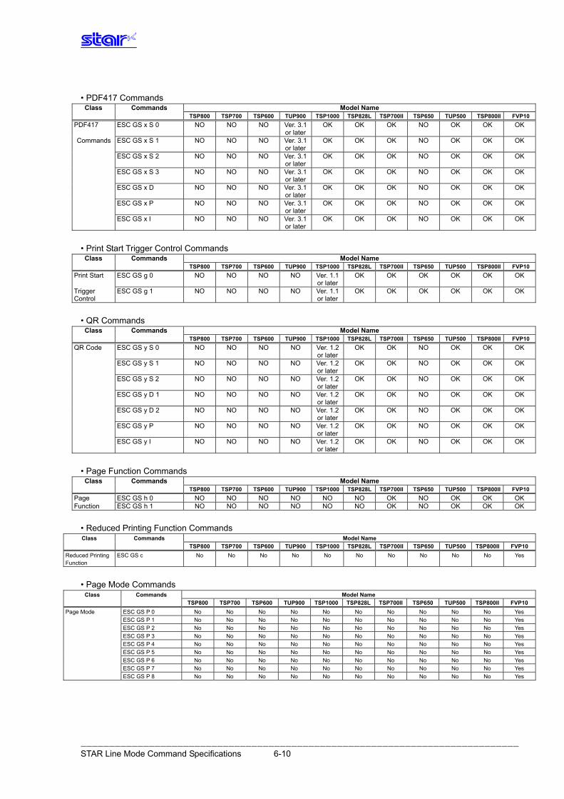
――――――――――――――――――――――――――――――――――――――――――――――――――――――――――――――――――――――――――――― STAR Line Mode Command Specifications 6-10
• PDF417 Commands
Class Commands Model Name TSP800 TSP700 TSP600 TUP900 TSP1000 TSP828L TSP700II TSP650 TUP500 TSP800II FVP10PDF417 ESC GS x S 0 NO NO NO Ver. 3.1
or laterOK OK OK NO OK OK OK
Commands ESC GS x S 1 NO NO NO Ver. 3.1 or later
OK OK OK NO OK OK OK
ESC GS x S 2 NO NO NO Ver. 3.1 or later
OK OK OK NO OK OK OK
ESC GS x S 3 NO NO NO Ver. 3.1 or later
OK OK OK NO OK OK OK
ESC GS x D NO NO NO Ver. 3.1 or later
OK OK OK NO OK OK OK
ESC GS x P NO NO NO Ver. 3.1 or later
OK OK OK NO OK OK OK
ESC GS x I NO NO NO Ver. 3.1 or later
OK OK OK NO OK OK OK
• Print Start Trigger Control Commands
Class Commands Model Name TSP800 TSP700 TSP600 TUP900 TSP1000 TSP828L TSP700II TSP650 TUP500 TSP800II FVP10Print Start ESC GS g 0 NO NO NO NO Ver. 1.1
or laterOK OK OK OK OK OK
Trigger Control
ESC GS g 1 NO NO NO NO Ver. 1.1 or later
OK OK OK OK OK OK
• QR Commands
Class Commands Model Name TSP800 TSP700 TSP600 TUP900 TSP1000 TSP828L TSP700II TSP650 TUP500 TSP800II FVP10QR Code ESC GS y S 0 NO NO NO NO Ver. 1.2
or laterOK OK NO OK OK OK
ESC GS y S 1 NO NO NO NO Ver. 1.2 or later
OK OK NO OK OK OK
ESC GS y S 2 NO NO NO NO Ver. 1.2 or later
OK OK NO OK OK OK
ESC GS y D 1 NO NO NO NO Ver. 1.2 or later
OK OK NO OK OK OK
ESC GS y D 2 NO NO NO NO Ver. 1.2 or later
OK OK NO OK OK OK
ESC GS y P NO NO NO NO Ver. 1.2 or later
OK OK NO OK OK OK
ESC GS y I NO NO NO NO Ver. 1.2 or later
OK OK NO OK OK OK
• Page Function Commands
Class Commands Model Name TSP800 TSP700 TSP600 TUP900 TSP1000 TSP828L TSP700II TSP650 TUP500 TSP800II FVP10Page ESC GS h 0 NO NO NO NO NO NO OK NO OK OK OK Function ESC GS h 1 NO NO NO NO NO NO OK NO OK OK OK
• Reduced Printing Function Commands Class Commands Model Name
TSP800 TSP700 TSP600 TUP900 TSP1000 TSP828L TSP700II TSP650 TUP500 TSP800II FVP10Reduced Printing Function
ESC GS c No No No No No No No No No No Yes
• Page Mode Commands Class Commands Model Name
TSP800 TSP700 TSP600 TUP900 TSP1000 TSP828L TSP700II TSP650 TUP500 TSP800II FVP10Page Mode ESC GS P 0 No No No No No No No No No No Yes ESC GS P 1 No No No No No No No No No No Yes ESC GS P 2 No No No No No No No No No No Yes ESC GS P 3 No No No No No No No No No No Yes ESC GS P 4 No No No No No No No No No No Yes ESC GS P 5 No No No No No No No No No No Yes ESC GS P 6 No No No No No No No No No No Yes ESC GS P 7 No No No No No No No No No No Yes ESC GS P 8 No No No No No No No No No No Yes
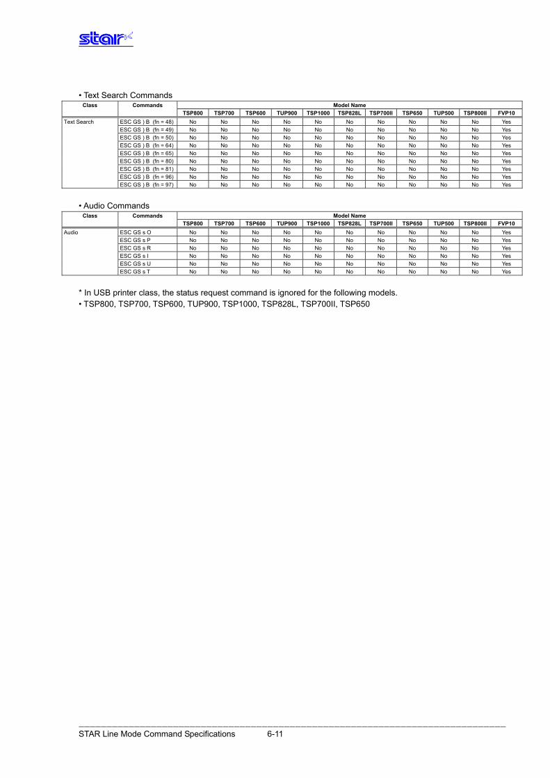
• Text Search Commands
Class Commands Model Name TSP800 TSP700II TSP650 TUP500 TSP700 TSP600 TUP900 TSP1000 TSP828L TSP800II FVP10
Text Search ESC GS ) B (fn = 48) No No No No No No No No No No Yes ESC GS ) B (fn = 49) No No No No No No No No No No Yes
ESC GS ) B (fn = 50) No No No No No No No No No No Yes
ESC GS ) B (fn = 64) No No No No No No No No No No Yes
ESC GS ) B (fn = 65) No No No No No No No No No No Yes
ESC GS ) B (fn = 80) No No No No No No No No No No Yes
ESC GS ) B (fn = 81) No No No No No No No No No No Yes
ESC GS ) B (fn = 96) No No No No No No No No No No Yes
ESC GS ) B (fn = 97) No No No No No No No No No No Yes
• Audio Commands
Class Commands Model Name TSP800 TSP700II TSP650 TUP500 TSP700 TSP600 TUP900 TSP1000 TSP828L TSP800II FVP10
Audio ESC GS s O No No No No No No No No No No Yes ESC GS s P No No No No No No No No No No Yes
ESC GS s R No No No No No No No No No No Yes
ESC GS s I No No No No No No No No No No Yes
ESC GS s U No No No No No No No No No No Yes
ESC GS s T No No No No No No No No No No Yes
* In USB printer class, the status request command is ignored for the following models. • TSP800, TSP700, TSP600, TUP900, TSP1000, TSP828L, TSP700II, TSP650
――――――――――――――――――――――――――――――――――――――――――――――――――――――――――――――――――――――――――――― STAR Line Mode Command Specifications 6-11
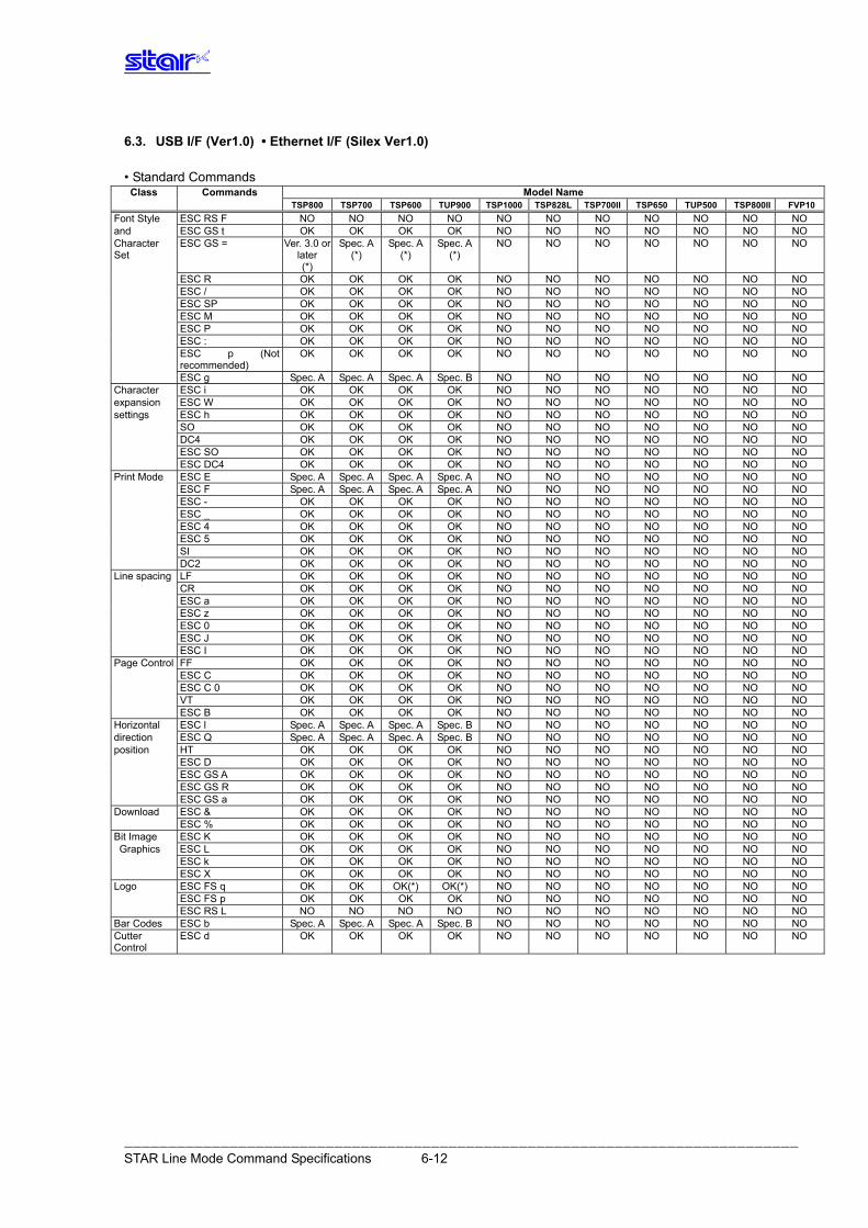
――――――――――――――――――――――――――――――――――――――――――――――――――――――――――――――――――――――――――――― STAR Line Mode Command Specifications 6-12
6.3. USB I/F (Ver1.0) • Ethernet I/F (Silex Ver1.0) • Standard Commands
Class Commands Model Name TSP800 TSP700 TSP600 TUP900 TSP1000 TSP828L TSP700II TSP650 TUP500 TSP800II FVP10Font Style ESC RS F NO NO NO NO NO NO NO NO NO NO NO and ESC GS t OK OK OK OK NO NO NO NO NO NO NO Character Set
ESC GS = Ver. 3.0 or later (*)
Spec. A(*)
Spec. A(*)
Spec. A(*)
NO NO NO NO NO NO NO
ESC R OK OK OK OK NO NO NO NO NO NO NO ESC / OK OK OK OK NO NO NO NO NO NO NO ESC SP OK OK OK OK NO NO NO NO NO NO NO ESC M OK OK OK OK NO NO NO NO NO NO NO ESC P OK OK OK OK NO NO NO NO NO NO NO ESC : OK OK OK OK NO NO NO NO NO NO NO ESC p (Not
recommended) OK OK OK OK NO NO NO NO NO NO NO
ESC g Spec. A Spec. A Spec. A Spec. B NO NO NO NO NO NO NO Character ESC i OK OK OK OK NO NO NO NO NO NO NO expansion ESC W OK OK OK OK NO NO NO NO NO NO NO settings ESC h OK OK OK OK NO NO NO NO NO NO NO SO OK OK OK OK NO NO NO NO NO NO NO DC4 OK OK OK OK NO NO NO NO NO NO NO ESC SO OK OK OK OK NO NO NO NO NO NO NO ESC DC4 OK OK OK OK NO NO NO NO NO NO NO Print Mode ESC E Spec. A Spec. A Spec. A Spec. A NO NO NO NO NO NO NO ESC F Spec. A Spec. A Spec. A Spec. A NO NO NO NO NO NO NO ESC - OK OK OK OK NO NO NO NO NO NO NO ESC _ OK OK OK OK NO NO NO NO NO NO NO ESC 4 OK OK OK OK NO NO NO NO NO NO NO ESC 5 OK OK OK OK NO NO NO NO NO NO NO SI OK OK OK OK NO NO NO NO NO NO NO DC2 OK OK OK OK NO NO NO NO NO NO NO Line spacing LF OK OK OK OK NO NO NO NO NO NO NO CR OK OK OK OK NO NO NO NO NO NO NO ESC a OK OK OK OK NO NO NO NO NO NO NO ESC z OK OK OK OK NO NO NO NO NO NO NO ESC 0 OK OK OK OK NO NO NO NO NO NO NO ESC J OK OK OK OK NO NO NO NO NO NO NO ESC I OK OK OK OK NO NO NO NO NO NO NO Page Control FF OK OK OK OK NO NO NO NO NO NO NO
ESC C OK OK OK OK NO NO NO NO NO NO NO ESC C 0 OK OK OK OK NO NO NO NO NO NO NO VT OK OK OK OK NO NO NO NO NO NO NO
ESC B OK OK OK OK NO NO NO NO NO NO NO Horizontal ESC l Spec. A Spec. A Spec. A Spec. B NO NO NO NO NO NO NO direction ESC Q Spec. A Spec. A Spec. A Spec. B NO NO NO NO NO NO NO position HT OK OK OK OK NO NO NO NO NO NO NO ESC D OK OK OK OK NO NO NO NO NO NO NO ESC GS A OK OK OK OK NO NO NO NO NO NO NO ESC GS R OK OK OK OK NO NO NO NO NO NO NO ESC GS a OK OK OK OK NO NO NO NO NO NO NO Download ESC & OK OK OK OK NO NO NO NO NO NO NO ESC % OK OK OK OK NO NO NO NO NO NO NO Bit Image ESC K OK OK OK OK NO NO NO NO NO NO NO Graphics ESC L OK OK OK OK NO NO NO NO NO NO NO
ESC k OK OK OK OK NO NO NO NO NO NO NO ESC X OK OK OK OK NO NO NO NO NO NO NO Logo ESC FS q OK OK OK(*) OK(*) NO NO NO NO NO NO NO ESC FS p OK OK OK OK NO NO NO NO NO NO NO ESC RS L NO NO NO NO NO NO NO NO NO NO NO Bar Codes ESC b Spec. A Spec. A Spec. A Spec. B NO NO NO NO NO NO NO Cutter Control
ESC d OK OK OK OK NO NO NO NO NO NO NO
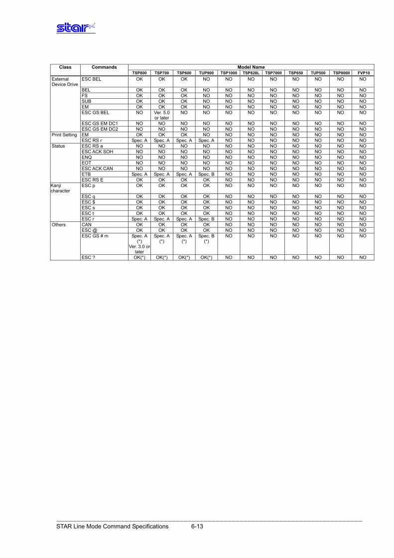
――――――――――――――――――――――――――――――――――――――――――――――――――――――――――――――――――――――――――――― STAR Line Mode Command Specifications 6-13
Class Commands Model Name
TSP800 TSP700 TSP600 TUP900 TSP1000 TSP828L TSP700II TSP650 TUP500 TSP800II FVP10External Device Drive
ESC BEL OK OK OK NO NO NO NO NO NO NO NO
BEL OK OK OK NO NO NO NO NO NO NO NO FS OK OK OK NO NO NO NO NO NO NO NO SUB OK OK OK NO NO NO NO NO NO NO NO EM OK OK OK NO NO NO NO NO NO NO NO ESC GS BEL NO Ver. 5.0
or laterNO NO NO NO NO NO NO NO NO
ESC GS EM DC1 NO NO NO NO NO NO NO NO NO NO NO ESC GS EM DC2 NO NO NO NO NO NO NO NO NO NO NO Print Setting EM OK OK OK NO NO NO NO NO NO NO NO ESC RS r Spec. A Spec. A Spec. A Spec. A NO NO NO NO NO NO NO Status ESC RS a NO NO NO NO NO NO NO NO NO NO NO ESC ACK SOH NO NO NO NO NO NO NO NO NO NO NO ENQ NO NO NO NO NO NO NO NO NO NO NO EOT NO NO NO NO NO NO NO NO NO NO NO ESC ACK CAN NO NO NO NO NO NO NO NO NO NO NO ETB Spec. A Spec. A Spec. A Spec. B NO NO NO NO NO NO NO ESC RS E OK OK OK OK NO NO NO NO NO NO NO Kanji character
ESC p OK OK OK OK NO NO NO NO NO NO NO
ESC q OK OK OK OK NO NO NO NO NO NO NO ESC $ OK OK OK OK NO NO NO NO NO NO NO ESC s OK OK OK OK NO NO NO NO NO NO NO ESC t OK OK OK OK NO NO NO NO NO NO NO ESC r Spec. A Spec. A Spec. A Spec. B NO NO NO NO NO NO NO Others CAN OK OK OK OK NO NO NO NO NO NO NO ESC @ OK OK OK OK NO NO NO NO NO NO NO ESC GS # m Spec. A
(*) Ver. 3.0 or
later
Spec. A(*)
Spec. A(*)
Spec. B(*)
NO NO NO NO NO NO NO
ESC ? OK(*) OK(*) OK(*) OK(*) NO NO NO NO NO NO NO
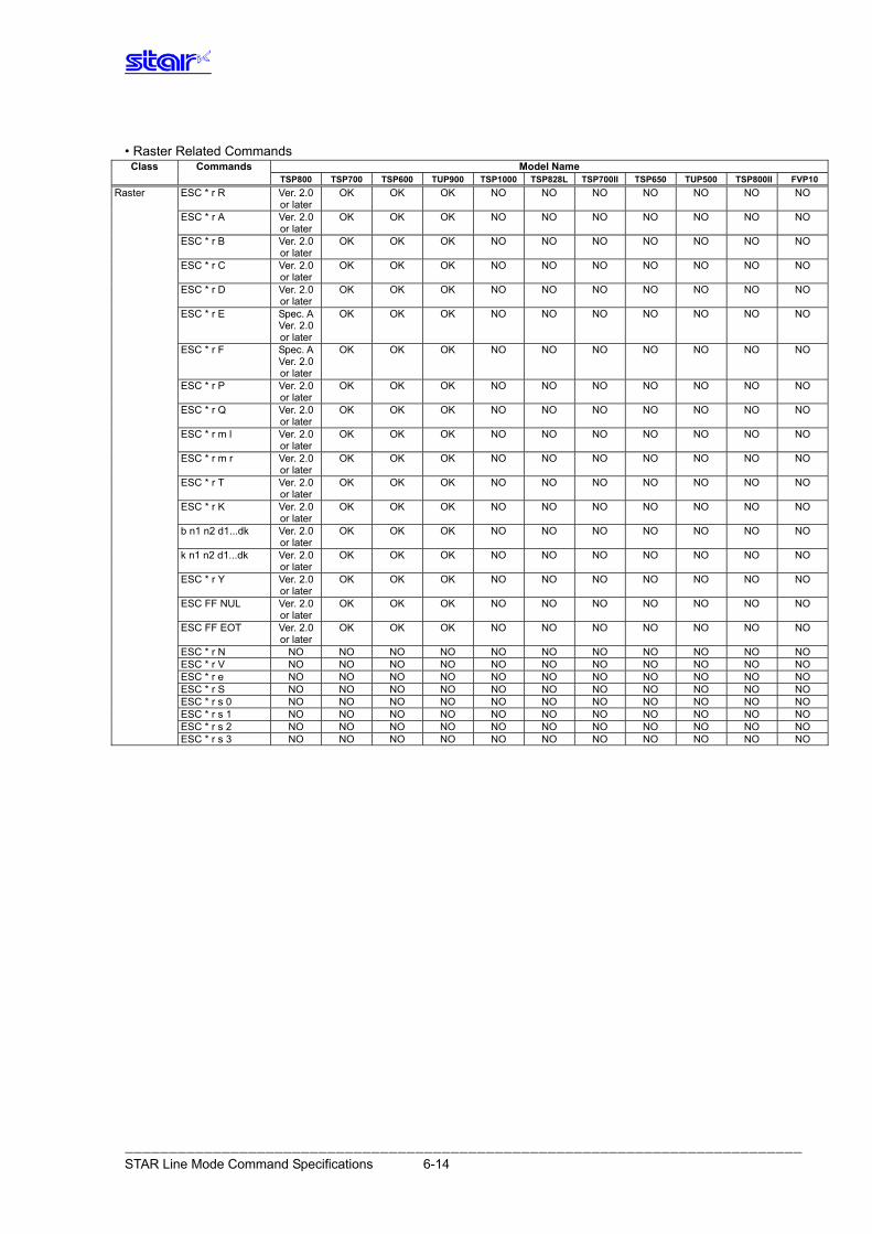
――――――――――――――――――――――――――――――――――――――――――――――――――――――――――――――――――――――――――――― STAR Line Mode Command Specifications 6-14
• Raster Related Commands
Class Commands Model Name TSP800 TSP700 TSP600 TUP900 TSP1000 TSP828L TSP700II TSP650 TUP500 TSP800II FVP10Raster ESC * r R Ver. 2.0
or later OK OK OK NO NO NO NO NO NO NO
ESC * r A Ver. 2.0 or later
OK OK OK NO NO NO NO NO NO NO
ESC * r B Ver. 2.0 or later
OK OK OK NO NO NO NO NO NO NO
ESC * r C Ver. 2.0 or later
OK OK OK NO NO NO NO NO NO NO
ESC * r D Ver. 2.0 or later
OK OK OK NO NO NO NO NO NO NO
ESC * r E Spec. A Ver. 2.0 or later
OK OK OK NO NO NO NO NO NO NO
ESC * r F Spec. A Ver. 2.0 or later
OK OK OK NO NO NO NO NO NO NO
ESC * r P Ver. 2.0 or later
OK OK OK NO NO NO NO NO NO NO
ESC * r Q Ver. 2.0 or later
OK OK OK NO NO NO NO NO NO NO
ESC * r m l Ver. 2.0 or later
OK OK OK NO NO NO NO NO NO NO
ESC * r m r Ver. 2.0 or later
OK OK OK NO NO NO NO NO NO NO
ESC * r T Ver. 2.0 or later
OK OK OK NO NO NO NO NO NO NO
ESC * r K Ver. 2.0 or later
OK OK OK NO NO NO NO NO NO NO
b n1 n2 d1...dk Ver. 2.0 or later
OK OK OK NO NO NO NO NO NO NO
k n1 n2 d1...dk Ver. 2.0 or later
OK OK OK NO NO NO NO NO NO NO
ESC * r Y Ver. 2.0 or later
OK OK OK NO NO NO NO NO NO NO
ESC FF NUL Ver. 2.0 or later
OK OK OK NO NO NO NO NO NO NO
ESC FF EOT Ver. 2.0 or later
OK OK OK NO NO NO NO NO NO NO
ESC * r N NO NO NO NO NO NO NO NO NO NO NO ESC * r V NO NO NO NO NO NO NO NO NO NO NO ESC * r e NO NO NO NO NO NO NO NO NO NO NO ESC * r S NO NO NO NO NO NO NO NO NO NO NO ESC * r s 0 NO NO NO NO NO NO NO NO NO NO NO ESC * r s 1 NO NO NO NO NO NO NO NO NO NO NO ESC * r s 2 NO NO NO NO NO NO NO NO NO NO NO ESC * r s 3 NO NO NO NO NO NO NO NO NO NO NO
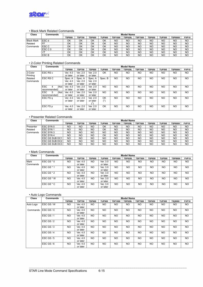
――――――――――――――――――――――――――――――――――――――――――――――――――――――――――――――――――――――――――――― STAR Line Mode Command Specifications 6-15
• Black Mark Related Commands Class Commands Model Name
TSP800 TSP700 TSP600 TUP900 TSP1000 TSP828L TSP700II TSP650 TUP500 TSP800II FVP10Black Mark ESC d OK OK OK OK NO NO NO NO NO NO NO Related FF OK OK OK OK NO NO NO NO NO NO NO Commands ESC C OK OK OK OK NO NO NO NO NO NO NO ESC C 0 OK OK OK OK NO NO NO NO NO NO NO VT OK OK OK OK NO NO NO NO NO NO NO ESC B OK OK OK OK NO NO NO NO NO NO NO
• 2-Color Printing Related Commands
Class Commands Model Name TSP800 TSP700 TSP600 TUP900 TSP1000 TSP828L TSP700II TSP650 TUP500 TSP800II FVP102-Color Printing
ESC RS c Ver. 4.0 or later
Ver. 2.0 or later
Ver. 2.0 or later
OK NO NO NO NO NO NO NO
Related Commands
ESC RS C Spec. A Ver. 4.0 or later
Spec. AVer. 2.0 or later
Spec. AVer. 2.0 or later
Spec. B NO NO NO NO NO NO NO
ESC 4 (Not recommended)
Ver. 4.0 or later
Ver. 2.0 or later
Ver. 2.0 or later
NO NO NO NO NO NO NO NO
ESC 5 (Not recommended)
Ver. 4.0 or later
Ver. 2.0 or later
Ver. 2.0 or later
NO NO NO NO NO NO NO NO
ESC FS q Ver. 4.0 or later
Ver. 2.0 or later
Ver. 2.0 or later
(*)
OK (*)
NO NO NO NO NO NO NO
ESC FS p Ver. 4.0 or later
Ver. 2.0 or later
Ver. 2.0 or later
OK NO NO NO NO NO NO NO
• Presenter Related Commands
Class Commands Model Name TSP800 TSP700 TSP600 TUP900 TSP1000 TSP828L TSP700II TSP650 TUP500 TSP800II FVP10 Presenter ESC SYN 0 NO NO NO OK NO NO NO NO NO NO NO Related ESC SYN 1 NO NO NO OK NO NO NO NO NO NO NO Commands ESC SYN 3 NO NO NO NO NO NO NO NO NO NO NO ESC SYN 4 NO NO NO OK NO NO NO NO NO NO NO ESC GS SUB DC1 NO NO NO NO NO NO NO NO NO NO NO ESC GS SUB DC2 NO NO NO NO NO NO NO NO NO NO NO ESC GS SUB DC3 NO NO NO NO NO NO NO NO NO NO NO
• Mark Commands
Class Commands Model Name TSP800 TSP700 TSP600 TUP900 TSP1000 TSP828L TSP700II TSP650 TUP500 TSP800II FVP10Mark Commands
ESC GS * 0 NO Ver. 4.0 or later
NO Ver. 3.0 or later
NO NO NO NO NO NO NO
ESC GS * 1 NO Ver. 4.0 or later
NO Ver. 3.0 or later
NO NO NO NO NO NO NO
ESC GS * 2 NO Ver. 4.0 or later
NO Ver. 3.0 or later
NO NO NO NO NO NO NO
ESC GS * W NO Ver. 4.0 or later
NO Ver. 3.0 or later
NO NO NO NO NO NO NO
ESC GS * C NO Ver. 4.0 or later
NO Ver. 3.0 or later
NO NO NO NO NO NO NO
• Auto Logo Commands
Class Commands Model Name TSP800 TSP700 TSP600 TUP900 TSP1000 TSP828L TSP700II TSP650 TUP500 TS{800II FVP10Auto Logo ESC GS / W NO Ver. 4.0
or laterNO NO NO NO NO NO NO NO NO
Commands ESC GS / C NO Ver. 4.0 or later
NO NO NO NO NO NO NO NO NO
ESC GS / 1 NO Ver. 4.0 or later
NO NO NO NO NO NO NO NO NO
ESC GS / 2 NO Ver. 4.0 or later
NO NO NO NO NO NO NO NO NO
ESC GS / 3 NO Ver. 4.0 or later
NO NO NO NO NO NO NO NO NO
ESC GS / 4 NO Ver. 4.0 or later
NO NO NO NO NO NO NO NO NO
ESC GS / 5 NO Ver. 4.0 or later
NO NO NO NO NO NO NO NO NO
ESC GS / 6 NO Ver. 4.0 or later
NO NO NO NO NO NO NO NO NO
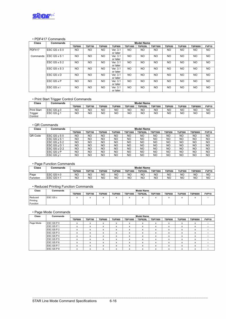
――――――――――――――――――――――――――――――――――――――――――――――――――――――――――――――――――――――――――――― STAR Line Mode Command Specifications 6-16
• PDF417 Commands
Class Commands Model Name TSP800 TSP700 TSP600 TUP900 TSP1000 TSP828L TSP700II TSP650 TUP500 TSP800II FVP10PDF417 ESC GS x S 0 NO NO NO Ver. 3.1
or laterNO NO NO NO NO NO NO
Commands ESC GS x S 1 NO NO NO Ver. 3.1 or later
NO NO NO NO NO NO NO
ESC GS x S 2 NO NO NO Ver. 3.1 or later
NO NO NO NO NO NO NO
ESC GS x S 3 NO NO NO Ver. 3.1 or later
NO NO NO NO NO NO NO
ESC GS x D NO NO NO Ver. 3.1 or later
NO NO NO NO NO NO NO
ESC GS x P NO NO NO Ver. 3.1 or later
NO NO NO NO NO NO NO
ESC GS x I NO NO NO Ver. 3.1 or later
NO NO NO NO NO NO NO
• Print Start Trigger Control Commands
Class Commands Model Name TSP800 TSP700 TSP600 TUP900 TSP1000 TSP828L TSP700II TSP650 TUP500 TSP800II FVP10Print Start ESC GS g 0 NO NO NO NO NO NO NO NO NO NO NO Trigger Control
ESC GS g 1 NO NO NO NO NO NO NO NO NO NO NO
• QR Commands
Class Commands Model Name TSP800 TSP700 TSP600 TUP900 TSP1000 TSP828L TSP700II TSP650 TUP500 TSP800II FVP10 QR Code ESC GS y S 0 NO NO NO NO NO NO NO NO NO NO NO ESC GS y S 1 NO NO NO NO NO NO NO NO NO NO NO ESC GS y S 2 NO NO NO NO NO NO NO NO NO NO NO ESC GS y D 1 NO NO NO NO NO NO NO NO NO NO NO ESC GS y D 2 NO NO NO NO NO NO NO NO NO NO NO ESC GS y P NO NO NO NO NO NO NO NO NO NO NO ESC GS y I NO NO NO NO NO NO NO NO NO NO NO
• Page Function Commands
Class Commands Model Name TSP800 TSP700 TSP600 TUP900 TSP1000 TSP828L TSP700II TSP650 TUP500 TSP800II FVP10Page ESC GS h 0 NO NO NO NO NO NO NO NO NO NO NO Function ESC GS h 1 NO NO NO NO NO NO NO NO NO NO NO
• Reduced Printing Function Commands Class Commands Model Name
TSP800 TSP700 TSP600 TUP900 TSP1000 TSP828L TSP700II TSP650 TUP500 TSP800II FVP10Reduced Printing Function
ESC GS c x x x x x x x x x x ○
• Page Mode Commands Class Commands Model Name
TSP800 TSP700 TSP600 TUP900 TSP1000 TSP828L TSP700II TSP650 TUP500 TSP800II FVP10Page Mode ESC GS P 0 x x x x x x x x x x ○ ESC GS P 1 x x x x x x x x x x ○ ESC GS P 2 x x x x x x x x x x ○ ESC GS P 3 x x x x x x x x x x ○ ESC GS P 4 x x x x x x x x x x ○ ESC GS P 5 x x x x x x x x x x ○ ESC GS P 6 x x x x x x x x x x ○ ESC GS P 7 x x x x x x x x x x ○ ESC GS P 8 x x x x x x x x x x ○
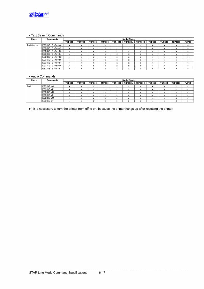
• Text Search Commands
Class Commands Model Name TSP800 TSP700II TSP650 TUP500 TSP700 TSP600 TUP900 TSP1000 TSP828L TSP800II FVP10
Text Search ESC GS ) B (fn = 48) x x x x x x x x x x ○ ESC GS ) B (fn = 49) x x x x x x x x x x ○
ESC GS ) B (fn = 50) x x x x x x x x x x ○
ESC GS ) B (fn = 64) x x x x x x x x x x ○
ESC GS ) B (fn = 65) x x x x x x x x x x ○
ESC GS ) B (fn = 80) x x x x x x x x x x ○
ESC GS ) B (fn = 81) x x x x x x x x x x ○
ESC GS ) B (fn = 96) x x x x x x x x x x ○
ESC GS ) B (fn = 97) x x x x x x x x x x ○
• Audio Commands
Class Commands Model Name TSP800 TSP700II TSP650 TUP500 TSP700 TSP600 TUP900 TSP1000 TSP828L TSP800II FVP10
Audio ESC GS s O x x x x x x x x x x ○ ESC GS s P x x x x x x x x x x ○
ESC GS s R x x x x x x x x x x ○
ESC GS s I x x x x x x x x x x ○
ESC GS s U x x x x x x x x x x ○
ESC GS s T x x x x x x x x x x ○
(*) It is necessary to turn the printer from off to on, because the printer hangs up after resetting the printer.
――――――――――――――――――――――――――――――――――――――――――――――――――――――――――――――――――――――――――――― STAR Line Mode Command Specifications 6-17
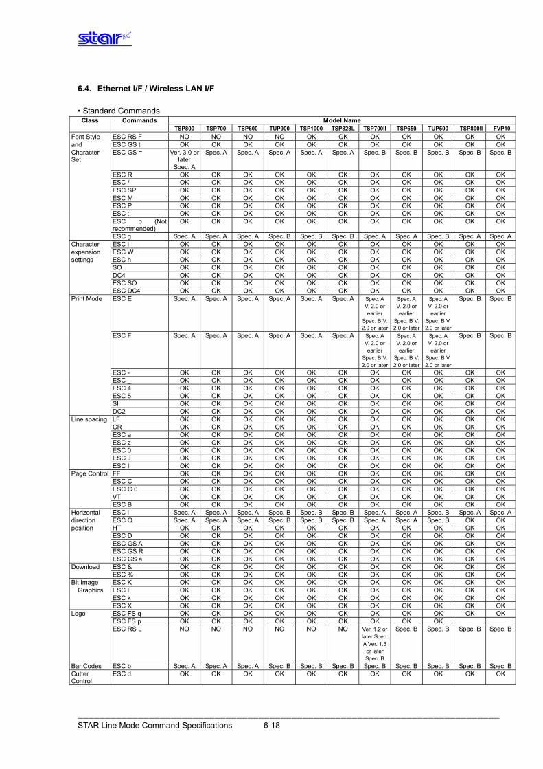
――――――――――――――――――――――――――――――――――――――――――――――――――――――――――――――――――――――――――――― STAR Line Mode Command Specifications 6-18
6.4. Ethernet I/F / Wireless LAN I/F • Standard Commands
Class Commands Model Name TSP800 TSP700 TSP600 TUP900 TSP1000 TSP828L TSP700II TSP650 TUP500 TSP800II FVP10Font Style ESC RS F NO NO NO NO OK OK OK OK OK OK OK and ESC GS t OK OK OK OK OK OK OK OK OK OK OK Character Set
ESC GS = Ver. 3.0 or later
Spec. A
Spec. A Spec. A Spec. A Spec. A Spec. A Spec. B Spec. B Spec. B Spec. B Spec. B
ESC R OK OK OK OK OK OK OK OK OK OK OK ESC / OK OK OK OK OK OK OK OK OK OK OK ESC SP OK OK OK OK OK OK OK OK OK OK OK ESC M OK OK OK OK OK OK OK OK OK OK OK ESC P OK OK OK OK OK OK OK OK OK OK OK ESC : OK OK OK OK OK OK OK OK OK OK OK ESC p (Not
recommended) OK OK OK OK OK OK OK OK OK OK OK
ESC g Spec. A Spec. A Spec. A Spec. B Spec. B Spec. B Spec. A Spec. A Spec. B Spec. A Spec. ACharacter ESC i OK OK OK OK OK OK OK OK OK OK OK expansion ESC W OK OK OK OK OK OK OK OK OK OK OK settings ESC h OK OK OK OK OK OK OK OK OK OK OK SO OK OK OK OK OK OK OK OK OK OK OK DC4 OK OK OK OK OK OK OK OK OK OK OK ESC SO OK OK OK OK OK OK OK OK OK OK OK ESC DC4 OK OK OK OK OK OK OK OK OK OK OK Print Mode ESC E Spec. A Spec. A Spec. A Spec. A Spec. A Spec. A Spec. A
V. 2.0 or earlier
Spec. B V. 2.0 or later
Spec. A V. 2.0 or earlier
Spec. B V. 2.0 or later
Spec. A V. 2.0 or earlier
Spec. B V. 2.0 or later
Spec. B Spec. B
ESC F Spec. A Spec. A Spec. A Spec. A Spec. A Spec. A Spec. A V. 2.0 or earlier
Spec. B V. 2.0 or later
Spec. A V. 2.0 or earlier
Spec. B V. 2.0 or later
Spec. A V. 2.0 or earlier
Spec. B V. 2.0 or later
Spec. B Spec. B
ESC - OK OK OK OK OK OK OK OK OK OK OK ESC _ OK OK OK OK OK OK OK OK OK OK OK ESC 4 OK OK OK OK OK OK OK OK OK OK OK ESC 5 OK OK OK OK OK OK OK OK OK OK OK SI OK OK OK OK OK OK OK OK OK OK OK DC2 OK OK OK OK OK OK OK OK OK OK OK Line spacing LF OK OK OK OK OK OK OK OK OK OK OK CR OK OK OK OK OK OK OK OK OK OK OK ESC a OK OK OK OK OK OK OK OK OK OK OK ESC z OK OK OK OK OK OK OK OK OK OK OK ESC 0 OK OK OK OK OK OK OK OK OK OK OK ESC J OK OK OK OK OK OK OK OK OK OK OK ESC I OK OK OK OK OK OK OK OK OK OK OK Page Control FF OK OK OK OK OK OK OK OK OK OK OK
ESC C OK OK OK OK OK OK OK OK OK OK OK ESC C 0 OK OK OK OK OK OK OK OK OK OK OK VT OK OK OK OK OK OK OK OK OK OK OK
ESC B OK OK OK OK OK OK OK OK OK OK OK Horizontal ESC l Spec. A Spec. A Spec. A Spec. B Spec. B Spec. B Spec. A Spec. A Spec. B Spec. A Spec. Adirection ESC Q Spec. A Spec. A Spec. A Spec. B Spec. B Spec. B Spec. A Spec. A Spec. B OK OK position HT OK OK OK OK OK OK OK OK OK OK OK ESC D OK OK OK OK OK OK OK OK OK OK OK ESC GS A OK OK OK OK OK OK OK OK OK OK OK ESC GS R OK OK OK OK OK OK OK OK OK OK OK ESC GS a OK OK OK OK OK OK OK OK OK OK OK Download ESC & OK OK OK OK OK OK OK OK OK OK OK ESC % OK OK OK OK OK OK OK OK OK OK OK Bit Image ESC K OK OK OK OK OK OK OK OK OK OK OK
Graphics ESC L OK OK OK OK OK OK OK OK OK OK OK ESC k OK OK OK OK OK OK OK OK OK OK OK ESC X OK OK OK OK OK OK OK OK OK OK OK Logo ESC FS q OK OK OK OK OK OK OK OK OK OK OK ESC FS p OK OK OK OK OK OK OK OK OK ESC RS L NO NO NO NO NO NO Ver. 1.2 or
later Spec. A Ver. 1.3
or later Spec. B
Spec. B Spec. B Spec. B Spec. B
Bar Codes ESC b Spec. A Spec. A Spec. A Spec. B Spec. B Spec. B Spec. B Spec. B Spec. B Spec. B Spec. BCutter Control
ESC d OK OK OK OK OK OK OK OK OK OK OK
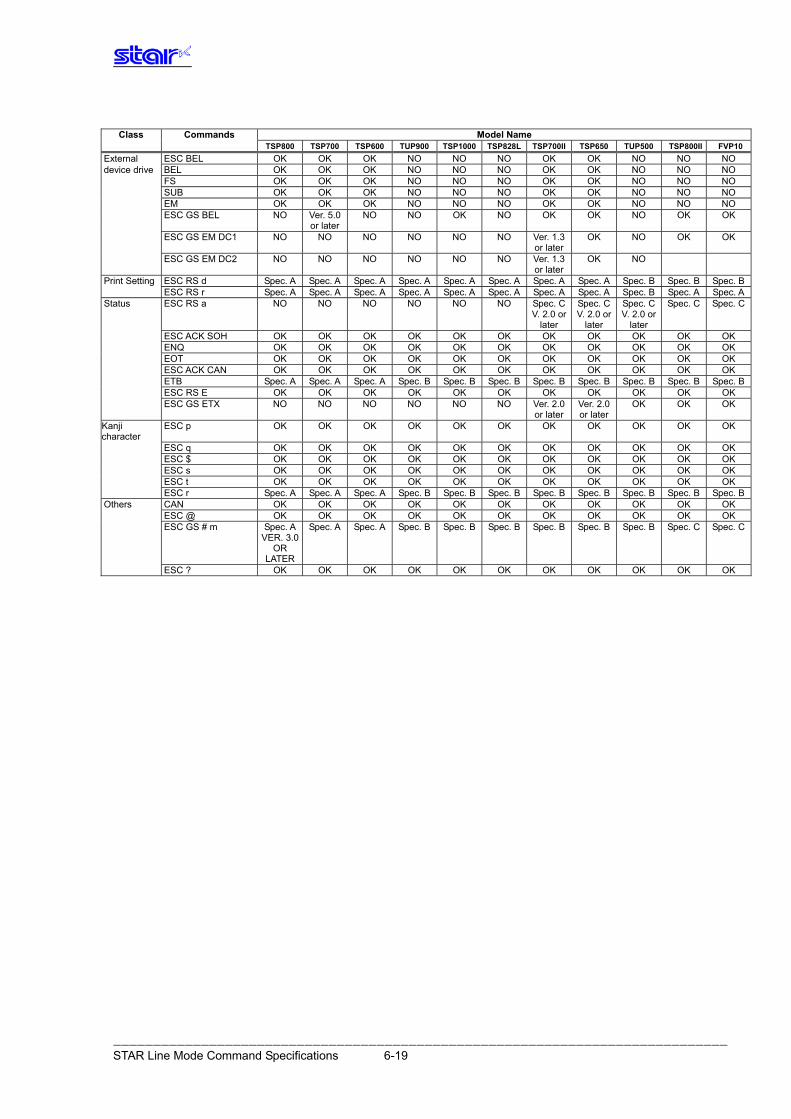
――――――――――――――――――――――――――――――――――――――――――――――――――――――――――――――――――――――――――――― STAR Line Mode Command Specifications 6-19
Class Commands Model Name
TSP800 TSP700 TSP600 TUP900 TSP1000 TSP828L TSP700II TSP650 TUP500 TSP800II FVP10External ESC BEL OK OK OK NO NO NO OK OK NO NO NO device drive BEL OK OK OK NO NO NO OK OK NO NO NO FS OK OK OK NO NO NO OK OK NO NO NO SUB OK OK OK NO NO NO OK OK NO NO NO EM OK OK OK NO NO NO OK OK NO NO NO ESC GS BEL NO Ver. 5.0
or laterNO NO OK NO OK OK NO OK OK
ESC GS EM DC1 NO NO NO NO NO NO Ver. 1.3 or later
OK NO OK OK
ESC GS EM DC2 NO NO NO NO NO NO Ver. 1.3 or later
OK NO
Print Setting ESC RS d Spec. A Spec. A Spec. A Spec. A Spec. A Spec. A Spec. A Spec. A Spec. B Spec. B Spec. B ESC RS r Spec. A Spec. A Spec. A Spec. A Spec. A Spec. A Spec. A Spec. A Spec. B Spec. A Spec. AStatus ESC RS a NO NO NO NO NO NO Spec. C
V. 2.0 or later
Spec. C V. 2.0 or
later
Spec. CV. 2.0 or
later
Spec. C Spec. C
ESC ACK SOH OK OK OK OK OK OK OK OK OK OK OK ENQ OK OK OK OK OK OK OK OK OK OK OK EOT OK OK OK OK OK OK OK OK OK OK OK ESC ACK CAN OK OK OK OK OK OK OK OK OK OK OK ETB Spec. A Spec. A Spec. A Spec. B Spec. B Spec. B Spec. B Spec. B Spec. B Spec. B Spec. B ESC RS E OK OK OK OK OK OK OK OK OK OK OK ESC GS ETX NO NO NO NO NO NO Ver. 2.0
or later Ver. 2.0 or later
OK OK OK
Kanji character
ESC p OK OK OK OK OK OK OK OK OK OK OK
ESC q OK OK OK OK OK OK OK OK OK OK OK ESC $ OK OK OK OK OK OK OK OK OK OK OK ESC s OK OK OK OK OK OK OK OK OK OK OK ESC t OK OK OK OK OK OK OK OK OK OK OK ESC r Spec. A Spec. A Spec. A Spec. B Spec. B Spec. B Spec. B Spec. B Spec. B Spec. B Spec. BOthers CAN OK OK OK OK OK OK OK OK OK OK OK ESC @ OK OK OK OK OK OK OK OK OK OK OK ESC GS # m Spec. A
VER. 3.0 OR
LATER
Spec. A Spec. A Spec. B Spec. B Spec. B Spec. B Spec. B Spec. B Spec. C Spec. C
ESC ? OK OK OK OK OK OK OK OK OK OK OK
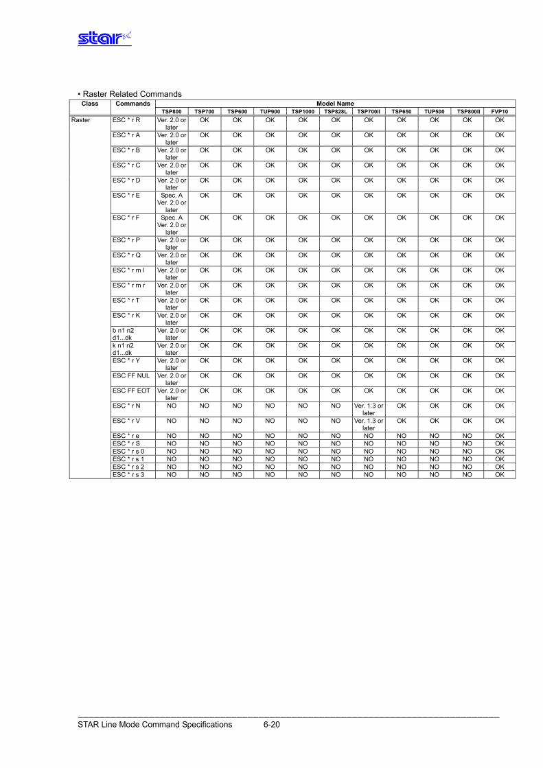
――――――――――――――――――――――――――――――――――――――――――――――――――――――――――――――――――――――――――――― STAR Line Mode Command Specifications 6-20
• Raster Related Commands
Class Commands Model Name TSP800 TSP700 TSP600 TUP900 TSP1000 TSP828L TSP700II TSP650 TUP500 TSP800II FVP10 Raster ESC * r R Ver. 2.0 or
later OK OK OK OK OK OK OK OK OK OK
ESC * r A Ver. 2.0 or later
OK OK OK OK OK OK OK OK OK OK
ESC * r B Ver. 2.0 or later
OK OK OK OK OK OK OK OK OK OK
ESC * r C Ver. 2.0 or later
OK OK OK OK OK OK OK OK OK OK
ESC * r D Ver. 2.0 or later
OK OK OK OK OK OK OK OK OK OK
ESC * r E Spec. A Ver. 2.0 or
later
OK OK OK OK OK OK OK OK OK OK
ESC * r F Spec. A Ver. 2.0 or
later
OK OK OK OK OK OK OK OK OK OK
ESC * r P Ver. 2.0 or later
OK OK OK OK OK OK OK OK OK OK
ESC * r Q Ver. 2.0 or later
OK OK OK OK OK OK OK OK OK OK
ESC * r m l Ver. 2.0 or later
OK OK OK OK OK OK OK OK OK OK
ESC * r m r Ver. 2.0 or later
OK OK OK OK OK OK OK OK OK OK
ESC * r T Ver. 2.0 or later
OK OK OK OK OK OK OK OK OK OK
ESC * r K Ver. 2.0 or later
OK OK OK OK OK OK OK OK OK OK
b n1 n2 d1...dk
Ver. 2.0 or later
OK OK OK OK OK OK OK OK OK OK
k n1 n2 d1...dk
Ver. 2.0 or later
OK OK OK OK OK OK OK OK OK OK
ESC * r Y Ver. 2.0 or later
OK OK OK OK OK OK OK OK OK OK
ESC FF NUL Ver. 2.0 or later
OK OK OK OK OK OK OK OK OK OK
ESC FF EOT Ver. 2.0 or later
OK OK OK OK OK OK OK OK OK OK
ESC * r N NO NO NO NO NO NO Ver. 1.3 or later
OK OK OK OK
ESC * r V NO NO NO NO NO NO Ver. 1.3 or later
OK OK OK OK
ESC * r e NO NO NO NO NO NO NO NO NO NO OK ESC * r S NO NO NO NO NO NO NO NO NO NO OK ESC * r s 0 NO NO NO NO NO NO NO NO NO NO OK ESC * r s 1 NO NO NO NO NO NO NO NO NO NO OK ESC * r s 2 NO NO NO NO NO NO NO NO NO NO OK ESC * r s 3 NO NO NO NO NO NO NO NO NO NO OK
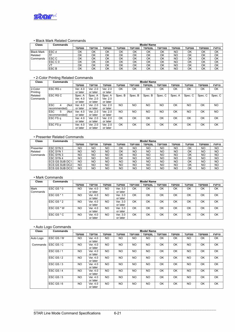
――――――――――――――――――――――――――――――――――――――――――――――――――――――――――――――――――――――――――――― STAR Line Mode Command Specifications 6-21
• Black Mark Related Commands
Class Commands Model Name TSP800 TSP700 TSP600 TUP900 TSP1000 TSP828L TSP700II TSP650 TUP500 TSP800II FVP10Black Mark ESC d OK OK OK OK OK OK OK NO OK OK OK Related FF OK OK OK OK OK OK OK NO OK OK OK Commands ESC C OK OK OK OK OK OK OK NO OK OK OK ESC C 0 OK OK OK OK OK OK OK NO OK OK OK VT OK OK OK OK OK OK OK NO OK OK OK ESC B OK OK OK OK OK OK OK NO OK OK OK
• 2-Color Printing Related Commands
Class Commands Model Name TSP800 TSP700 TSP600 TUP900 TSP1000 TSP828L TSP700II TSP650 TUP500 TSP800II FVP102-Color Printing
ESC RS c Ver. 4.0 or later
Ver. 2.0 or later
Ver. 2.0 or later
OK OK OK OK OK OK OK OK
Related Commands
ESC RS C Spec. A Ver. 4.0 or later
Spec. AVer. 2.0 or later
Spec. AVer. 2.0 or later
Spec. B Spec. B Spec. B Spec. C Spec. A Spec. C Spec. C Spec. C
ESC 4 (Not recommended)
Ver. 4.0 or later
Ver. 2.0 or later
Ver. 2.0 or later
NO NO NO NO OK NO OK NO
ESC 5 (Not recommended)
Ver. 4.0 or later
Ver. 2.0 or later
Ver. 2.0 or later
NO NO NO NO OK NO OK NO
ESC FS q Ver. 4.0 or later
Ver. 2.0 or later
Ver. 2.0 or later
OK OK OK OK OK OK OK OK
ESC FS p Ver. 4.0 or later
Ver. 2.0 or later
Ver. 2.0 or later
OK OK OK OK OK OK OK OK
• Presenter Related Commands
Class Commands Model Name TSP800 TSP700 TSP600 TUP900 TSP1000 TSP828L TSP700II TSP650 TUP500 TSP800II FVP10Presenter ESC SYN 0 NO NO NO OK NO NO NO NO OK NO NO Related ESC SYN 1 NO NO NO OK NO NO NO NO OK NO NO Commands ESC SYN 3 NO NO NO OK NO NO NO NO OK NO NO ESC SYN 4 NO NO NO OK NO NO NO NO OK NO NO ECS GS SUB DC1 NO NO NO NO NO NO NO NO OK NO NO ECS GS SUB DC2 NO NO NO NO NO NO NO NO OK NO NO ECS GS SUB DC3 NO NO NO NO NO NO NO NO OK NO NO
• Mark Commands
Class Commands Model Name TSP800 TSP700 TSP600 TUP900 TSP1000 TSP828L TSP700II TSP650 TUP500 TSP800II FVP10Mark Commands
ESC GS * 0 NO Ver. 4.0 or later
NO Ver. 3.0 or later
OK OK OK OK OK OK OK
ESC GS * 1 NO Ver. 4.0 or later
NO Ver. 3.0 or later
OK OK OK OK OK OK OK
ESC GS * 2 NO Ver. 4.0 or later
NO Ver. 3.0 or later
OK OK OK OK OK OK OK
ESC GS * W NO Ver. 4.0 or later
NO Ver. 3.0 or later
OK OK OK OK OK OK OK
ESC GS * C NO Ver. 4.0 or later
NO Ver. 3.0 or later
OK OK OK OK OK OK OK
• Auto Logo Commands
Class Commands Model Name TSP800 TSP700 TSP600 TUP900 TSP1000 TSP828L TSP700II TSP650 TUP500 TSP800II FVP10Auto Logo ESC GS / W NO Ver. 4.0
or laterNO NO NO NO OK OK NO OK OK
Commands ESC GS / C NO Ver. 4.0 or later
NO NO NO NO OK OK NO OK OK
ESC GS / 1 NO Ver. 4.0 or later
NO NO NO NO OK OK NO OK OK
ESC GS / 2 NO Ver. 4.0 or later
NO NO NO NO OK OK NO OK OK
ESC GS / 3 NO Ver. 4.0 or later
NO NO NO NO OK OK NO OK OK
ESC GS / 4 NO Ver. 4.0 or later
NO NO NO NO OK OK NO OK OK
ESC GS / 5 NO Ver. 4.0 or later
NO NO NO NO OK OK NO OK OK
ESC GS / 6 NO Ver. 4.0 or later
NO NO NO NO OK OK NO OK OK
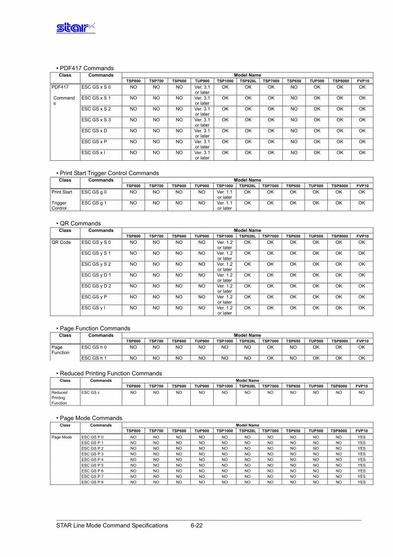
――――――――――――――――――――――――――――――――――――――――――――――――――――――――――――――――――――――――――――― STAR Line Mode Command Specifications 6-22
• PDF417 Commands
Class Commands Model Name TSP800 TSP700 TSP600 TUP900 TSP1000 TSP828L TSP700II TSP650 TUP500 TSP800II FVP10PDF417 ESC GS x S 0 NO NO NO Ver. 3.1
or laterOK OK OK NO OK OK OK
Commands
ESC GS x S 1 NO NO NO Ver. 3.1 or later
OK OK OK NO OK OK OK
ESC GS x S 2 NO NO NO Ver. 3.1 or later
OK OK OK NO OK OK OK
ESC GS x S 3 NO NO NO Ver. 3.1 or later
OK OK OK NO OK OK OK
ESC GS x D NO NO NO Ver. 3.1 or later
OK OK OK NO OK OK OK
ESC GS x P NO NO NO Ver. 3.1 or later
OK OK OK NO OK OK OK
ESC GS x I NO NO NO Ver. 3.1 or later
OK OK OK NO OK OK OK
• Print Start Trigger Control Commands
Class Commands Model Name TSP800 TSP700 TSP600 TUP900 TSP1000 TSP828L TSP700II TSP650 TUP500 TSP800II FVP10Print Start ESC GS g 0 NO NO NO NO Ver. 1.1
or laterOK OK OK OK OK OK
Trigger Control
ESC GS g 1 NO NO NO NO Ver. 1.1 or later
OK OK OK OK OK OK
• QR Commands
Class Commands Model Name TSP800 TSP700 TSP600 TUP900 TSP1000 TSP828L TSP700II TSP650 TUP500 TSP800II FVP10QR Code ESC GS y S 0 NO NO NO NO Ver. 1.2
or laterOK OK OK OK OK OK
ESC GS y S 1 NO NO NO NO Ver. 1.2 or later
OK OK OK OK OK OK
ESC GS y S 2 NO NO NO NO Ver. 1.2 or later
OK OK OK OK OK OK
ESC GS y D 1 NO NO NO NO Ver. 1.2 or later
OK OK OK OK OK OK
ESC GS y D 2 NO NO NO NO Ver. 1.2 or later
OK OK OK OK OK OK
ESC GS y P NO NO NO NO Ver. 1.2 or later
OK OK OK OK OK OK
ESC GS y I NO NO NO NO Ver. 1.2 or later
OK OK OK OK OK OK
• Page Function Commands
Class Commands Model Name TSP800 TSP700 TSP600 TUP900 TSP1000 TSP828L TSP700II TSP650 TUP500 TSP800II FVP10Page Function
ESC GS h 0 NO NO NO NO NO NO OK NO OK OK OK
ESC GS h 1 NO NO NO NO NO NO OK NO OK OK OK • Reduced Printing Function Commands
Class Commands Model Name TSP800 TSP700 TSP600 TUP900 TSP1000 TSP828L TSP700II TSP650 TUP500 TSP800II FVP10Reduced Printing Function
ESC GS c NO NO NO NO NO NO NO NO NO NO NO
• Page Mode Commands Class Commands Model Name
TSP800 TSP700 TSP600 TUP900 TSP1000 TSP828L TSP700II TSP650 TUP500 TSP800II FVP10Page Mode ESC GS P 0 NO NO NO NO NO NO NO NO NO NO YES ESC GS P 1 NO NO NO NO NO NO NO NO NO NO YES ESC GS P 2 NO NO NO NO NO NO NO NO NO NO YES ESC GS P 3 NO NO NO NO NO NO NO NO NO NO YES ESC GS P 4 NO NO NO NO NO NO NO NO NO NO YES ESC GS P 5 NO NO NO NO NO NO NO NO NO NO YES ESC GS P 6 NO NO NO NO NO NO NO NO NO NO YES ESC GS P 7 NO NO NO NO NO NO NO NO NO NO YES ESC GS P 8 NO NO NO NO NO NO NO NO NO NO YES
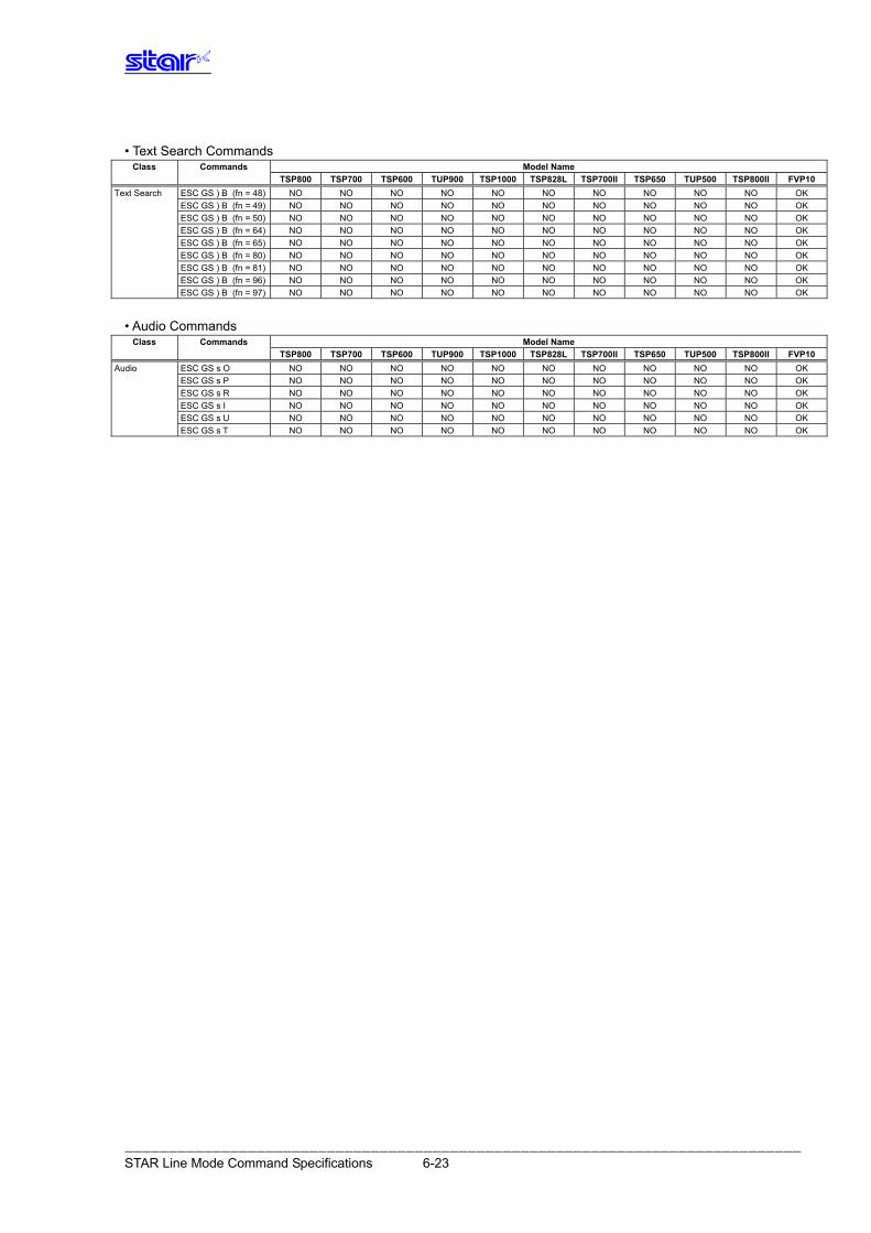
• Text Search Commands
Class Commands Model Name TSP800 TSP700II TSP650 TUP500 TSP700 TSP600 TUP900 TSP1000 TSP828L TSP800II FVP10
Text Search ESC GS ) B (fn = 48) NO NO NO NO NO NO NO NO NO NO OK ESC GS ) B (fn = 49) NO NO NO NO NO NO NO NO NO NO OK
ESC GS ) B (fn = 50) NO NO NO NO NO NO NO NO NO NO OK
ESC GS ) B (fn = 64) NO NO NO NO NO NO NO NO NO NO OK
ESC GS ) B (fn = 65) NO NO NO NO NO NO NO NO NO NO OK
ESC GS ) B (fn = 80) NO NO NO NO NO NO NO NO NO NO OK
ESC GS ) B (fn = 81) NO NO NO NO NO NO NO NO NO NO OK
ESC GS ) B (fn = 96) NO NO NO NO NO NO NO NO NO NO OK
ESC GS ) B (fn = 97) NO NO NO NO NO NO NO NO NO NO OK
• Audio Commands
Class Commands Model Name TSP800 TSP700II TSP650 TUP500 TSP700 TSP600 TUP900 TSP1000 TSP828L TSP800II FVP10
Audio ESC GS s O NO NO NO NO NO NO NO NO NO NO OK ESC GS s P NO NO NO NO NO NO NO NO NO NO OK
ESC GS s R NO NO NO NO NO NO NO NO NO NO OK
ESC GS s I NO NO NO NO NO NO NO NO NO NO OK
ESC GS s U NO NO NO NO NO NO NO NO NO NO OK
ESC GS s T NO NO NO NO NO NO NO NO NO NO OK
――――――――――――――――――――――――――――――――――――――――――――――――――――――――――――――――――――――――――――― STAR Line Mode Command Specifications 6-23
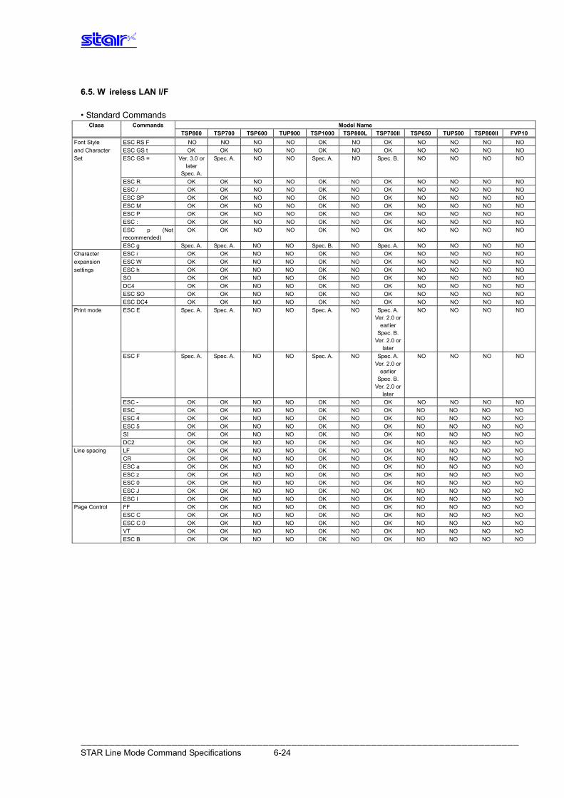
――――――――――――――――――――――――――――――――――――――――――――――――――――――――――――――――――――――――――――― STAR Line Mode Command Specifications 6-24
6.5. W ireless LAN I/F • Standard Commands
Class Commands Model Name TSP800 TSP700 TSP600 TUP900 TSP1000 TSP800L TSP700II TSP650 TUP500 TSP800II FVP10Font Style ESC RS F NO NO NO NO OK NO OK NO NO NO NO and Character ESC GS t OK OK NO NO OK NO OK NO NO NO NO Set ESC GS = Ver. 3.0 or
later Spec. A.
Spec. A. NO NO Spec. A. NO Spec. B. NO NO NO NO
ESC R OK OK NO NO OK NO OK NO NO NO NO ESC / OK OK NO NO OK NO OK NO NO NO NO ESC SP OK OK NO NO OK NO OK NO NO NO NO ESC M OK OK NO NO OK NO OK NO NO NO NO ESC P OK OK NO NO OK NO OK NO NO NO NO ESC : OK OK NO NO OK NO OK NO NO NO NO ESC p (Not
recommended) OK OK NO NO OK NO OK NO NO NO NO
ESC g Spec. A. Spec. A. NO NO Spec. B. NO Spec. A. NO NO NO NO Character ESC i OK OK NO NO OK NO OK NO NO NO NO expansion ESC W OK OK NO NO OK NO OK NO NO NO NO settings ESC h OK OK NO NO OK NO OK NO NO NO NO SO OK OK NO NO OK NO OK NO NO NO NO DC4 OK OK NO NO OK NO OK NO NO NO NO ESC SO OK OK NO NO OK NO OK NO NO NO NO ESC DC4 OK OK NO NO OK NO OK NO NO NO NO Print mode ESC E Spec. A. Spec. A. NO NO Spec. A. NO Spec. A.
Ver. 2.0 or earlier
Spec. B. Ver. 2.0 or
later
NO NO NO NO
ESC F Spec. A. Spec. A. NO NO Spec. A. NO Spec. A.Ver. 2.0 or
earlierSpec. B.
Ver. 2.0 or later
NO NO NO NO
ESC - OK OK NO NO OK NO OK NO NO NO NO ESC _ OK OK NO NO OK NO OK NO NO NO NO ESC 4 OK OK NO NO OK NO OK NO NO NO NO ESC 5 OK OK NO NO OK NO OK NO NO NO NO SI OK OK NO NO OK NO OK NO NO NO NO DC2 OK OK NO NO OK NO OK NO NO NO NO Line spacing LF OK OK NO NO OK NO OK NO NO NO NO CR OK OK NO NO OK NO OK NO NO NO NO ESC a OK OK NO NO OK NO OK NO NO NO NO ESC z OK OK NO NO OK NO OK NO NO NO NO ESC 0 OK OK NO NO OK NO OK NO NO NO NO ESC J OK OK NO NO OK NO OK NO NO NO NO ESC I OK OK NO NO OK NO OK NO NO NO NO Page Control FF OK OK NO NO OK NO OK NO NO NO NO
ESC C OK OK NO NO OK NO OK NO NO NO NO ESC C 0 OK OK NO NO OK NO OK NO NO NO NO VT OK OK NO NO OK NO OK NO NO NO NO
ESC B OK OK NO NO OK NO OK NO NO NO NO
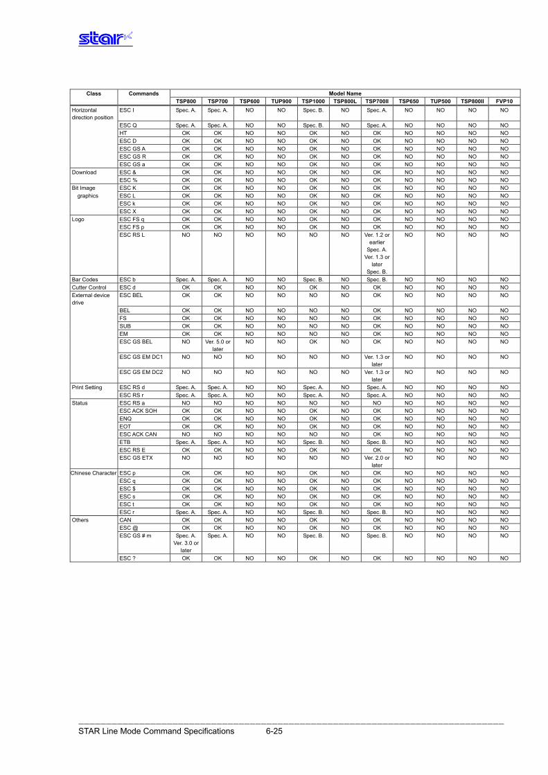
――――――――――――――――――――――――――――――――――――――――――――――――――――――――――――――――――――――――――――― STAR Line Mode Command Specifications 6-25
Class Commands Model Name
TSP800 TSP700 TSP600 TUP900 TSP1000 TSP800L TSP700II TSP650 TUP500 TSP800II FVP10Horizontal direction position
ESC I Spec. A. Spec. A. NO NO Spec. B. NO Spec. A. NO NO NO NO
ESC Q Spec. A. Spec. A. NO NO Spec. B. NO Spec. A. NO NO NO NO HT OK OK NO NO OK NO OK NO NO NO NO ESC D OK OK NO NO OK NO OK NO NO NO NO ESC GS A OK OK NO NO OK NO OK NO NO NO NO ESC GS R OK OK NO NO OK NO OK NO NO NO NO ESC GS a OK OK NO NO OK NO OK NO NO NO NO Download ESC & OK OK NO NO OK NO OK NO NO NO NO ESC % OK OK NO NO OK NO OK NO NO NO NO Bit Image ESC K OK OK NO NO OK NO OK NO NO NO NO
graphics ESC L OK OK NO NO OK NO OK NO NO NO NO ESC k OK OK NO NO OK NO OK NO NO NO NO ESC X OK OK NO NO OK NO OK NO NO NO NO Logo ESC FS q OK OK NO NO OK NO OK NO NO NO NO ESC FS p OK OK NO NO OK NO OK NO NO NO NO ESC RS L NO NO NO NO NO NO Ver. 1.2 or
earlierSpec. A.
Ver. 1.3 or later
Spec. B.
NO NO NO NO
Bar Codes ESC b Spec. A. Spec. A. NO NO Spec. . B NO Spec. . B NO NO NO NO Cutter Control ESC d OK OK NO NO OK NO OK NO NO NO NO External device drive
ESC BEL OK OK NO NO NO NO OK NO NO NO NO
BEL OK OK NO NO NO NO OK NO NO NO NO FS OK OK NO NO NO NO OK NO NO NO NO SUB OK OK NO NO NO NO OK NO NO NO NO EM OK OK NO NO NO NO OK NO NO NO NO ESC GS BEL NO Ver. 5.0 or
later NO NO OK NO OK NO NO NO NO
ESC GS EM DC1 NO NO NO NO NO NO Ver. 1.3 or later
NO NO NO NO
ESC GS EM DC2 NO NO NO NO NO NO Ver. 1.3 or later
NO NO NO NO
Print Setting ESC RS d Spec. A. Spec. A. NO NO Spec. A. NO Spec. A. NO NO NO NO ESC RS r Spec. A. Spec. A. NO NO Spec. A. NO Spec. A. NO NO NO NO Status ESC RS a NO NO NO NO NO NO NO NO NO NO NO ESC ACK SOH OK OK NO NO OK NO OK NO NO NO NO ENQ OK OK NO NO OK NO OK NO NO NO NO EOT OK OK NO NO OK NO OK NO NO NO NO ESC ACK CAN NO NO NO NO NO NO OK NO NO NO NO ETB Spec. A. Spec. A. NO NO Spec. B. NO Spec. B. NO NO NO NO ESC RS E OK OK NO NO OK NO OK NO NO NO NO ESC GS ETX NO NO NO NO NO NO Ver. 2.0 or
later NO NO NO NO
Chinese Character ESC p OK OK NO NO OK NO OK NO NO NO NO ESC q OK OK NO NO OK NO OK NO NO NO NO ESC $ OK OK NO NO OK NO OK NO NO NO NO ESC s OK OK NO NO OK NO OK NO NO NO NO ESC t OK OK NO NO OK NO OK NO NO NO NO ESC r Spec. A. Spec. A. NO NO Spec. B. NO Spec. B. NO NO NO NO Others CAN OK OK NO NO OK NO OK NO NO NO NO ESC @ OK OK NO NO OK NO OK NO NO NO NO ESC GS # m Spec. A.
Ver. 3.0 or later
Spec. A. NO NO Spec. B. NO Spec. B. NO NO NO NO
ESC ? OK OK NO NO OK NO OK NO NO NO NO
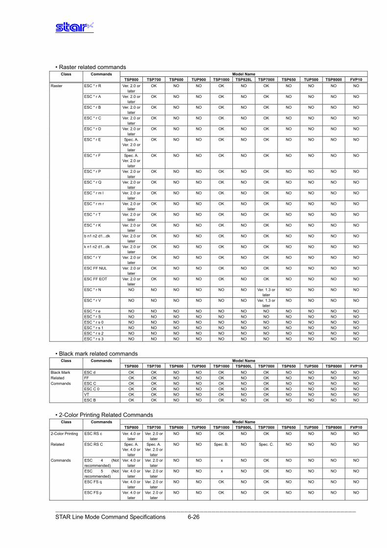
――――――――――――――――――――――――――――――――――――――――――――――――――――――――――――――――――――――――――――― STAR Line Mode Command Specifications 6-26
• Raster related commands
Class Commands Model Name TSP800 TSP700 TSP600 TUP900 TSP1000 TSP828L TSP700II TSP650 TUP500 TSP800II FVP10Raster ESC * r R Ver. 2.0 or
later OK NO NO OK NO OK NO NO NO NO
ESC * r A Ver. 2.0 or later
OK NO NO OK NO OK NO NO NO NO
ESC * r B Ver. 2.0 or later
OK NO NO OK NO OK NO NO NO NO
ESC * r C Ver. 2.0 or later
OK NO NO OK NO OK NO NO NO NO
ESC * r D Ver. 2.0 or later
OK NO NO OK NO OK NO NO NO NO
ESC * r E Spec. A. Ver. 2.0 or
later
OK NO NO OK NO OK NO NO NO NO
ESC * r F Spec. A. Ver. 2.0 or
later
OK NO NO OK NO OK NO NO NO NO
ESC * r P Ver. 2.0 or later
OK NO NO OK NO OK NO NO NO NO
ESC * r Q Ver. 2.0 or later
OK NO NO OK NO OK NO NO NO NO
ESC * r m l Ver. 2.0 or later
OK NO NO OK NO OK NO NO NO NO
ESC * r m r Ver. 2.0 or later
OK NO NO OK NO OK NO NO NO NO
ESC * r T Ver. 2.0 or later
OK NO NO OK NO OK NO NO NO NO
ESC * r K Ver. 2.0 or later
OK NO NO OK NO OK NO NO NO NO
b n1 n2 d1...dk Ver. 2.0 or later
OK NO NO OK NO OK NO NO NO NO
k n1 n2 d1...dk Ver. 2.0 or later
OK NO NO OK NO OK NO NO NO NO
ESC * r Y Ver. 2.0 or later
OK NO NO OK NO OK NO NO NO NO
ESC FF NUL Ver. 2.0 or later
OK NO NO OK NO OK NO NO NO NO
ESC FF EOT Ver. 2.0 or later
OK NO NO OK NO OK NO NO NO NO
ESC * r N NO NO NO NO NO NO Ver. 1.3 or later
NO NO NO NO
ESC * r V NO NO NO NO NO NO Ver. 1.3 or later
NO NO NO NO
ESC * r e NO NO NO NO NO NO NO NO NO NO NO ESC * r S NO NO NO NO NO NO NO NO NO NO NO ESC * r s 0 NO NO NO NO NO NO NO NO NO NO NO ESC * r s 1 NO NO NO NO NO NO NO NO NO NO NO ESC * r s 2 NO NO NO NO NO NO NO NO NO NO NO ESC * r s 3 NO NO NO NO NO NO NO NO NO NO NO
• Black mark related commands
Class Commands Model Name TSP800 TSP700 TSP600 TUP900 TSP1000 TSP800L TSP700II TSP650 TUP500 TSP800II FVP10Black Mark ESC d OK OK NO NO OK NO OK NO NO NO NO Related FF OK OK NO NO OK NO OK NO NO NO NO Commands ESC C OK OK NO NO OK NO OK NO NO NO NO ESC C 0 OK OK NO NO OK NO OK NO NO NO NO VT OK OK NO NO OK NO OK NO NO NO NO ESC B OK OK NO NO OK NO OK NO NO NO NO
• 2-Color Printing Related Commands Class Commands Model Name
TSP800 TSP700 TSP600 TUP900 TSP1000 TSP800L TSP700II TSP650 TUP500 TSP800II FVP102-Color Printing ESC RS c Ver. 4.0 or
later Ver. 2.0 or
later NO NO OK NO OK NO NO NO NO
Related ESC RS C Spec. A. Ver. 4.0 or
later
Spec. A.Ver. 2.0 or
later
NO NO Spec. B. NO Spec. C. NO NO NO NO
Commands ESC 4 (Not recommended)
Ver. 4.0 or later
Ver. 2.0 or later
NO NO x NO OK NO NO NO NO
ESC 5 (Not recommended)
Ver. 4.0 or later
Ver. 2.0 or later
NO NO x NO OK NO NO NO NO
ESC FS q Ver. 4.0 or later
Ver. 2.0 or later
NO NO OK NO OK NO NO NO NO
ESC FS p Ver. 4.0 or later
Ver. 2.0 or later
NO NO OK NO OK NO NO NO NO
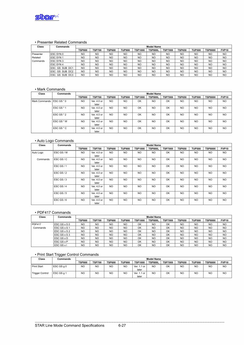
――――――――――――――――――――――――――――――――――――――――――――――――――――――――――――――――――――――――――――― STAR Line Mode Command Specifications 6-27
• Presenter Related Commands Class Commands Model Name
TSP800 TSP700 TSP600 TUP900 TSP1000 TSP800L TSP700II TSP650 TUP500 TSP800II FVP10Presenter ESC SYN 0 NO NO NO NO NO NO NO NO NO NO NO Related ESC SYN 1 NO NO NO NO NO NO NO NO NO NO NO Commands ESC SYN 3 NO NO NO NO NO NO NO NO NO NO NO ESC SYN 4 NO NO NO NO NO NO NO NO NO NO NO ESC GS SUB DC1 NO NO NO NO NO NO NO NO NO NO NO ESC GS SUB DC2 NO NO NO NO NO NO NO NO NO NO NO ESC GS SUB DC3 NO NO NO NO NO NO NO NO NO NO NO
• Mark Commands Class Commands Model Name
TSP800 TSP700 TSP600 TUP900 TSP1000 TSP800L TSP700II TSP650 TUP500 TSP800II FVP10Mark Commands ESC GS * 0 NO Ver. 4.0 or
later NO NO OK NO OK NO NO NO NO
ESC GS * 1 NO Ver. 4.0 or later
NO NO OK NO OK NO NO NO NO
ESC GS * 2 NO Ver. 4.0 or later
NO NO OK NO OK NO NO NO NO
ESC GS * W NO Ver. 4.0 or later
NO NO OK NO OK NO NO NO NO
ESC GS * C NO Ver. 4.0 or later
NO NO OK NO OK NO NO NO NO
• Auto Logo Commands
Class Commands Model Name TSP800 TSP700 TSP600 TUP900 TSP1000 TSP800L TSP700II TSP650 TUP500 TSP800II FVP10Auto Logo ESC GS / W NO Ver. 4.0 or
later NO NO NO NO OK NO NO NO NO
Commands ESC GS / C NO Ver. 4.0 or later
NO NO NO NO OK NO NO NO NO
ESC GS / 1 NO Ver. 4.0 or later
NO NO NO NO OK NO NO NO NO
ESC GS / 2 NO Ver. 4.0 or later
NO NO NO NO OK NO NO NO NO
ESC GS / 3 NO Ver. 4.0 or later
NO NO NO NO OK NO NO NO NO
ESC GS / 4 NO Ver. 4.0 or later
NO NO NO NO OK NO NO NO NO
ESC GS / 5 NO Ver. 4.0 or later
NO NO NO NO OK NO NO NO NO
ESC GS / 6 NO Ver. 4.0 or later
NO NO NO NO OK NO NO NO NO
• PDF417 Commands Class Commands Model Name
TSP800 TSP700 TSP600 TUP900 TSP1000 TSP800L TSP700II TSP650 TUP500 TSP800II FVP10PDF417 ESC GS x S 0 NO NO NO NO OK NO OK NO NO NO NO Commands ESC GS x S 1 NO NO NO NO OK NO OK NO NO NO NO
ESC GS x S 2 NO NO NO NO OK NO OK NO NO NO NO ESC GS x S 3 NO NO NO NO OK NO OK NO NO NO NO ESC GS x D NO NO NO NO OK NO OK NO NO NO NO ESC GS x P NO NO NO NO OK NO OK NO NO NO NO ESC GS x I NO NO NO NO OK NO OK NO NO NO NO
• Print Start Trigger Control Commands
Class Commands Model Name TSP800 TSP700 TSP600 TUP900 TSP1000 TSP800L TSP700II TSP650 TUP500 TSP800II FVP10Print Start ESC GS g 0 NO NO NO NO Ver. 1.1 or
later NO OK NO NO NO NO
Trigger Control ESC GS g 1 NO NO NO NO Ver. 1.1 or later
NO OK NO NO NO NO
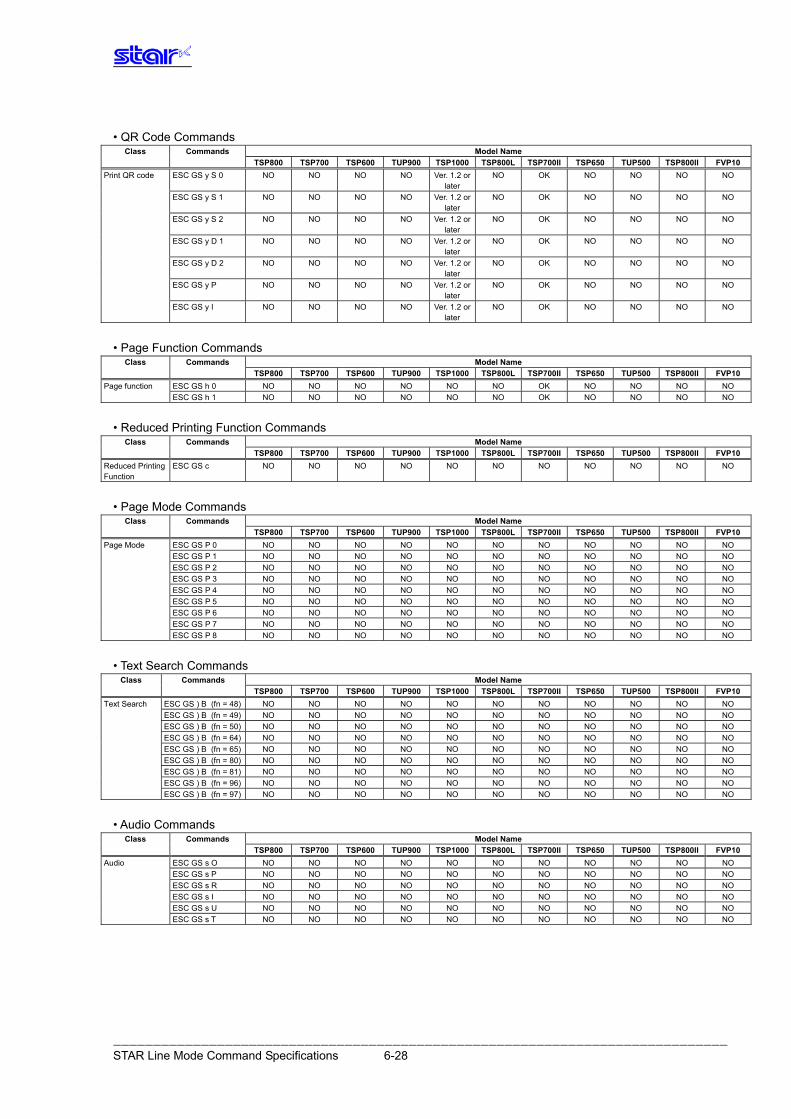
――――――――――――――――――――――――――――――――――――――――――――――――――――――――――――――――――――――――――――― STAR Line Mode Command Specifications 6-28
• QR Code Commands Class Commands Model Name
TSP800 TSP700 TSP600 TUP900 TSP1000 TSP800L TSP700II TSP650 TUP500 TSP800II FVP10Print QR code ESC GS y S 0 NO NO NO NO Ver. 1.2 or
later NO OK NO NO NO NO
ESC GS y S 1 NO NO NO NO Ver. 1.2 or later
NO OK NO NO NO NO
ESC GS y S 2 NO NO NO NO Ver. 1.2 or later
NO OK NO NO NO NO
ESC GS y D 1 NO NO NO NO Ver. 1.2 or later
NO OK NO NO NO NO
ESC GS y D 2 NO NO NO NO Ver. 1.2 or later
NO OK NO NO NO NO
ESC GS y P NO NO NO NO Ver. 1.2 or later
NO OK NO NO NO NO
ESC GS y I NO NO NO NO Ver. 1.2 or later
NO OK NO NO NO NO
• Page Function Commands Class Commands Model Name
TSP800 TSP700 TSP600 TUP900 TSP1000 TSP800L TSP700II TSP650 TUP500 TSP800II FVP10Page function ESC GS h 0 NO NO NO NO NO NO OK NO NO NO NO ESC GS h 1 NO NO NO NO NO NO OK NO NO NO NO
• Reduced Printing Function Commands Class Commands Model Name
TSP800 TSP700 TSP600 TUP900 TSP1000 TSP800L TSP700II TSP650 TUP500 TSP800II FVP10Reduced Printing Function
ESC GS c NO NO NO NO NO NO NO NO NO NO NO
• Page Mode Commands Class Commands Model Name
TSP800 TSP700 TSP600 TUP900 TSP1000 TSP800L TSP700II TSP650 TUP500 TSP800II FVP10Page Mode ESC GS P 0 NO NO NO NO NO NO NO NO NO NO NO ESC GS P 1 NO NO NO NO NO NO NO NO NO NO NO ESC GS P 2 NO NO NO NO NO NO NO NO NO NO NO ESC GS P 3 NO NO NO NO NO NO NO NO NO NO NO ESC GS P 4 NO NO NO NO NO NO NO NO NO NO NO ESC GS P 5 NO NO NO NO NO NO NO NO NO NO NO ESC GS P 6 NO NO NO NO NO NO NO NO NO NO NO ESC GS P 7 NO NO NO NO NO NO NO NO NO NO NO ESC GS P 8 NO NO NO NO NO NO NO NO NO NO NO
• Text Search Commands
Class Commands Model Name TSP800 TSP700 TSP600 TUP900 TSP1000 TSP800L TSP700II TSP650 TUP500 TSP800II FVP10Text Search ESC GS ) B (fn = 48) NO NO NO NO NO NO NO NO NO NO NO ESC GS ) B (fn = 49) NO NO NO NO NO NO NO NO NO NO NO ESC GS ) B (fn = 50) NO NO NO NO NO NO NO NO NO NO NO ESC GS ) B (fn = 64) NO NO NO NO NO NO NO NO NO NO NO ESC GS ) B (fn = 65) NO NO NO NO NO NO NO NO NO NO NO ESC GS ) B (fn = 80) NO NO NO NO NO NO NO NO NO NO NO ESC GS ) B (fn = 81) NO NO NO NO NO NO NO NO NO NO NO ESC GS ) B (fn = 96) NO NO NO NO NO NO NO NO NO NO NO ESC GS ) B (fn = 97) NO NO NO NO NO NO NO NO NO NO NO
• Audio Commands
Class Commands Model Name TSP800 TSP700 TSP600 TUP900 TSP1000 TSP800L TSP700II TSP650 TUP500 TSP800II FVP10Audio ESC GS s O NO NO NO NO NO NO NO NO NO NO NO ESC GS s P NO NO NO NO NO NO NO NO NO NO NO ESC GS s R NO NO NO NO NO NO NO NO NO NO NO ESC GS s I NO NO NO NO NO NO NO NO NO NO NO ESC GS s U NO NO NO NO NO NO NO NO NO NO NO ESC GS s T NO NO NO NO NO NO NO NO NO NO NO
Rev. 1.12 2010.05.10Printed in Japan, 80874577
SPECIAL PRODUCTS DIVISIONSTAR MICRONICS CO., LTD.536 Nanatsushinya, Shimizu-ku, Shizuoka, 424-0066 JapanTel: (int+81)-54-347-0112 Fax: (int+81)-54-347-0409
Please access the following URLhttp://www.star-m.jp/eng/dl/dl02.htmfor the latest revision of the manual.
OVERSEAS SUBSIDIARY COMPANIESSTAR MICRONICS AMERICA, INC.1150 King Georges Post Road, Edison, NJ 08837-3729 U.S.A.Tel: (int+1)-732-623-5555, Fax: (int+1)-732-623-5590
STAR MICRONICS EUROPE LTD.Star House, Peregrine Business Park, Gomm Road, High Wycombe, Bucks, HP13 7DL, U.K.Tel: (int+44)-1494-471111, Fax: (int+44)-1494-473333
STAR MICRONICS ASIA LTD.Rm. 1901-5, 19/F., Enterprise Square Two,3 Sheung Yuet Road, Kowloon Bay, Hong Kong Tel : (int+852)-2796-2727, Fax : (int+852)-2799-9344


![show access-group mode interface - Cisco€¦ · show access-group mode interface [interface interface-number] Syntax Description Defaults This command has no default settings. Command](https://img.pdfslide.net/doc/110x75/605498174543517f51389fe7/show-access-group-mode-interface-cisco-show-access-group-mode-interface-interface.jpg)

![T HE VI EDITOR. vi has 2 modes: command mode (initial or "default" mode) insert mode [Esc] is used to switch to command mode. In general, vi commands:](https://img.pdfslide.net/doc/110x75/56649ea25503460f94ba551b/t-he-vi-editor-vi-has-2-modes-command-mode-initial-or-default-mode-insert.jpg)