Embed Size (px)
Citation preview

© 2005 Directed Electronics, Inc. Vista, CA N564T 01-05
NOTE: This product is intended for installation by a professional installer only!Any attempt to install this product by any person other than a trained professionalmay result in severe damage to a vehicle’s electrical system and components.
MMooddeell 556644TTIInnssttaallllaattiioonn GGuuiiddee
HHoorrnneett
22 © 2005 Directed Electronics, Inc. Vista, CA
Bitwriter™, Code Hopping™, Doubleguard®, ESP™, FailSafe®, Ghost Switch™, Learn Routine™,Nite-Lite®, Nuisance Prevention Circuitry®, NPC®, Revenger®, Silent Mode™, Soft Chirp®,Stinger®, Valet®, Vehicle Recovery System®, VRS®, and Warn Away® are all Trademarks orRegistered Trademarks of Directed Electronics, Inc.
NNeeww SSooffttwwaarree CCoommppaattiibbiilliittyy ffoorr 110033TTKKeeyyppaadd
This unit now has software thatallows arming with entry delay whenused in conjunction with the optional110033TT Keypad. Refer to the 103TOwner’s Guide for details.
The Bitwriter® (p/n 998T)requires chip version 1.5 ornewer to program this unit.
© 2005 Directed Electronics, Inc. Vista, CA 33
ttaabbllee ooff ccoonntteennttsswwaarrnniinngg!! ssaaffeettyy ffiirrsstt .. .. .. .. .. .. .. .. .. .. .. .. .. .. .. .. .. .. .. .. .. .. .. .. 44
iinnssttaallllaattiioonn ppooiinnttss ttoo rreemmeemmbbeerr .. .. .. .. .. .. .. .. .. .. .. .. .. .. .. .. 55before beginning the installation . . . . . . . . . . . . 5after the installation . . . . . . . . . . . . . . . . . . . . . 5
ddeecciiddiinngg oonn ccoommppoonneenntt llooccaattiioonnss .. .. .. .. .. .. .. .. .. .. .. .. .. .. .. 66locations for the control module . . . . . . . . . . . . . 6locations for the siren . . . . . . . . . . . . . . . . . . . . 6locations for stinger doubleguard shock sensor . . . 7locations for valet/program switch . . . . . . . . . . . 8locations for the status LED . . . . . . . . . . . . . . . . 8
ffiinnddiinngg tthhee wwiirreess yyoouu nneeeedd.. .. .. .. .. .. .. .. .. .. .. .. .. .. .. .. .. .. .. .. 99locations for the optional starter kill relay . . . . . . 9locations for the relay satellite . . . . . . . . . . . . . . 9obtaining constant 12V . . . . . . . . . . . . . . . . . . . 9finding the starter wire . . . . . . . . . . . . . . . . . . 10finding the 12V switched ignition wire . . . . . . . . 10finding the tachometer wire . . . . . . . . . . . . . . . 11finding the wait-to-start bulb wire for diesels . . 11finding the accessory wire . . . . . . . . . . . . . . . . 11finding the door pin switch circuit. . . . . . . . . . . 12finding a (+) parking light wire . . . . . . . . . . . . . 12
mmaakkiinngg yyoouurr wwiirriinngg ccoonnnneeccttiioonnss .. .. .. .. .. .. .. .. .. .. .. .. .. .. .. 1133
pprriimmaarryy hhaarrnneessss ((HH11)),, 1122--ppiinn ccoonnnneeccttoorr .. .. .. .. .. .. .. .. .. .. 1144
aauuxxiilliiaarryy hhaarrnneessss ((HH22)),, 66--ppiinn ccoonnnneeccttoorr .. .. .. .. .. .. .. .. .. .. 1144
ddoooorr lloocckk hhaarrnneessss,, 33--ppiinn ccoonnnneeccttoorr .. .. .. .. .. .. .. .. .. .. .. .. .. 1155
rreemmoottee ssttaarrtt rriibbbboonn hhaarrnneessss,, wwiirriinngg ddiiaaggrraamm .. .. .. .. .. .. .. 1155
hheeaavvyy ggaauuggee rreellaayy ssaatteelllliittee wwiirriinngg ddiiaaggrraamm .. .. .. .. .. .. .. .. 1166
rreemmoottee ssttaarrtt hhaarrnneessss ((HH33)),, 55--ppiinn ccoonnnneeccttoorr .. .. .. .. .. .. .. 1166
pprriimmaarryy hhaarrnneessss ((HH11)) wwiirree ccoonnnneeccttiioonn gguuiiddee .. .. .. .. .. .. .. 1177
sseeccoonnddaarryy hhaarrnneessss ((HH22)) wwiirree ccoonnnneeccttiioonn gguuiiddee .. .. .. .. .. 2211
rreellaayy ssaatteelllliittee iinntteerrffaaccee wwiirree ccoonnnneeccttiioonn gguuiiddee .. .. .. .. .. 2233
rreemmoottee ssttaarrtt sseeccoonnddaarryy hhaarrnneessss ((HH33)) wwiirree ccoonnnneeccttiioonn gguuiiddee.. .. .. .. .. .. .. .. .. .. .. .. .. .. .. .. .. .. .. .. .. .. .. .. .. .. .. .. .. .. .. .. .. .. .. .. .. 2255
nneeuuttrraall ssaaffeettyy sswwiittcchh iinntteerrffaaccee .. .. .. .. .. .. .. .. .. .. .. .. .. .. .. .. 2266testing the neutral safety switch . . . . . . . . . . . . 27
bbyyppaassssiinngg GGMM vveehhiiccllee aannttii--tthheefftt ssyysstteemmss ((VVAATTSS)) .. .. .. .. 3300
11999955 aanndd nneewweerr vveehhiiccllee aannttii--tthheefftt ssyysstteemmss ((iimmmmoobbiilliizzeerrss)).. .. .. .. .. .. .. .. .. .. .. .. .. .. .. .. .. .. .. .. .. .. .. .. .. .. .. .. .. .. .. .. .. .. .. .. .. 3311
passlock I and passlock II (PL-1 and PL-2) . . . . . 31passkey III (PK-3), transponder-based systems . . 31
pplluugg--iinn LLEEDD aanndd vvaalleett//pprrooggrraamm sswwiittcchh .. .. .. .. .. .. .. .. .. .. .. 3322
pprrooggrraammmmeerr iinntteerrffaaccee,, 33--ppiinn bbllaacckk pplluugg .. .. .. .. .. .. .. .. .. .. 3322
sshhoocckk sseennssoorr hhaarrnneessss,, 44--ppiinn ccoonnnneeccttoorr .. .. .. .. .. .. .. .. .. .. .. 3333
ttaacchh lleeaarrnniinngg .. .. .. .. .. .. .. .. .. .. .. .. .. .. .. .. .. .. .. .. .. .. .. .. .. .. .. .. 3344
pprrooggrraammmmiinngg jjuummppeerrss .. .. .. .. .. .. .. .. .. .. .. .. .. .. .. .. .. .. .. .. .. .. 3344
ttrraannssmmiitttteerr//rreecceeiivveerr lleeaarrnn rroouuttiinnee™™ .. .. .. .. .. .. .. .. .. .. .. .. .. 3355tach threshold on/off . . . . . . . . . . . . . . . . . . . 35light flash (+)/(-) . . . . . . . . . . . . . . . . . . . . . . 35
ttrraannssmmiitttteerr ccoonnffiigguurraattiioonnss .. .. .. .. .. .. .. .. .. .. .. .. .. .. .. .. .. .. .. 3377standard configuration . . . . . . . . . . . . . . . . . . . 37
mmuullttii--lleevveell sseeccuurriittyy aarrmmiinngg .. .. .. .. .. .. .. .. .. .. .. .. .. .. .. .. .. .. .. 3388
ssyysstteemm ffeeaattuurreess lleeaarrnn rroouuttiinnee .. .. .. .. .. .. .. .. .. .. .. .. .. .. .. .. .. 3399
ffeeaattuurree mmeennuuss.. .. .. .. .. .. .. .. .. .. .. .. .. .. .. .. .. .. .. .. .. .. .. .. .. .. .. .. 4411menu #1 - basic features . . . . . . . . . . . . . . . . . 41menu #2 - advanced features . . . . . . . . . . . . . . 42menu #3 - remote start options. . . . . . . . . . . . . 42
ffeeaattuurree ddeessccrriippttiioonnss .. .. .. .. .. .. .. .. .. .. .. .. .. .. .. .. .. .. .. .. .. .. .. .. 4433menu #1 - basic features . . . . . . . . . . . . . . . . . 43menu #2 - advanced features . . . . . . . . . . . . . . 44menu #3 - remote start options. . . . . . . . . . . . . 46
nnuuiissaannccee pprreevveennttiioonn cciirrccuuiittrryy™™ .. .. .. .. .. .. .. .. .. .. .. .. .. .. .. .. 4488
vvaalleett mmooddee .. .. .. .. .. .. .. .. .. .. .. .. .. .. .. .. .. .. .. .. .. .. .. .. .. .. .. .. .. .. 4488
ttiimmeerr mmooddee.. .. .. .. .. .. .. .. .. .. .. .. .. .. .. .. .. .. .. .. .. .. .. .. .. .. .. .. .. .. 4499
ttaabbllee ooff zzoonneess.. .. .. .. .. .. .. .. .. .. .. .. .. .. .. .. .. .. .. .. .. .. .. .. .. .. .. .. 4499
sshhuuttddoowwnn ddiiaaggnnoossttiiccss .. .. .. .. .. .. .. .. .. .. .. .. .. .. .. .. .. .. .. .. .. .. 5500to perform shutdown diagnostics . . . . . . . . . . . . 50
lloonngg tteerrmm eevveenntt hhiissttoorryy .. .. .. .. .. .. .. .. .. .. .. .. .. .. .. .. .. .. .. .. .. 5500
ssaaffeettyy cchheecckk .. .. .. .. .. .. .. .. .. .. .. .. .. .. .. .. .. .. .. .. .. .. .. .. .. .. .. .. .. 5511
ttrroouubblleesshhoooottiinngg .. .. .. .. .. .. .. .. .. .. .. .. .. .. .. .. .. .. .. .. .. .. .. .. .. .. 5522alarm troubleshooting . . . . . . . . . . . . . . . . . . . 52remote start troubleshooting. . . . . . . . . . . . . . . 53
wwiirriinngg qquuiicckk rreeffeerreennccee gguuiiddee .. .. .. .. .. .. .. .. .. .. .. .. .. .. .. .. .. .. 5555
rreellaayy ssaatteelllliittee wwiirriinngg qquuiicckk rreeffeerreennccee gguuiiddee .. .. .. .. .. .. .. .. 5566
44 © 2005 Directed Electronics, Inc. Vista, CA
wwaarrnniinngg!! ssaaffeettyy ffiirrssttThe following safety warnings must be observed at all times:
■ Due to the complexity of this system, installation of this product must only be performed by an authorized
Directed Electronics dealer.
■ When properly installed, this system can start the vehicle via a command signal from the remote control
transmitter. Therefore, never operate the system in an area that does not have adequate ventilation. The fol-
lowing precautions are the sole responsibility of the user; however, authorized Directed Electronics dealers
should make the following recommendations to all users of this system:
1. Never operate the system in an enclosed or partially enclosed area without ventilation (such as a garage).
2. When parking in an enclosed or partially enclosed area or when having the vehicle serviced, the remote
start system must be disabled using the installed toggle switch.
3. It is the user's sole responsibility to properly handle and keep out of reach from children all remote
control transmitters to assure that the system does not unintentionally remote start the vehicle.
4. TTHHEE UUSSEERR MMUUSSTT IINNSSTTAALLLL AA CCAARRBBOONN MMOONNOOXXIIDDEE DDEETTEECCTTOORR IINN OORR AABBOOUUTT TTHHEE LLIIVVIINNGG AARREEAA AADDJJAACCEENNTT TTOO
TTHHEE VVEEHHIICCLLEE.. AALLLL DDOOOORRSS LLEEAADDIINNGG FFRROOMM AADDJJAACCEENNTT LLIIVVIINNGG AARREEAASS TTOO TTHHEE EENNCCLLOOSSEEDD OORR PPAARRTTIIAALLLLYY
EENNCCLLOOSSEEDD VVEEHHIICCLLEE SSTTOORRAAGGEE AARREEAA MMUUSSTT AATT AALLLL TTIIMMEESS RREEMMAAIINN CCLLOOSSEEDD..
■ Use of this product in a manner contrary to its intended mode of operation may result in property damage,
personal injury, or death. Except when performing the Safety Check outlined in this installation guide, (1)
Never remotely start the vehicle with the vehicle in gear, and (2) Never remotely start the vehicle with the
keys in the ignition. The user will be responsible for having the neutral safety feature of the vehicle period-
ically checked, wherein the vehicle must not remotely start while the car is in gear. This testing should be
performed by an authorized Directed Electronics dealer in accordance with the Safety Check outlined in this
product installation guide. If the vehicle starts in gear, cease remote start operation immediately and consult
with the user to fix the problem immediately.
■ After the remote start module has been installed, test the remote start module in accordance with the Safety
Check outlined in this installation guide. If the vehicle starts when performing the Neutral Safety Shutdown
Circuit test, the remote start unit has not been properly installed. The remote start module must be removed
or properly reinstalled so that the vehicle does not start in gear. All installations must be performed by an
authorized Directed Electronics dealer. OOPPEERRAATTIIOONN OOFF TTHHEE RREEMMOOTTEE SSTTAARRTT MMOODDUULLEE IIFF TTHHEE VVEEHHIICCLLEE SSTTAARRTTSS IINN
GGEEAARR IISS CCOONNTTRRAARRYY TTOO IITTSS IINNTTEENNDDEEDD MMOODDEE OOFF OOPPEERRAATTIIOONN.. OOPPEERRAATTIINNGG TTHHEE RREEMMOOTTEE SSTTAARRTT SSYYSSTTEEMM UUNNDDEERR
TTHHEESSEE CCOONNDDIITTIIOONNSS MMAAYY RREESSUULLTT IINN PPRROOPPEERRTTYY DDAAMMAAGGEE OORR PPEERRSSOONNAALL IINNJJUURRYY.. IIMMMMEEDDIIAATTEELLYY CCEEAASSEE TTHHEE UUSSEE
OOFF TTHHEE UUNNIITT AANNDD RREEPPAAIIRR OORR DDIISSCCOONNNNEECCTT TTHHEE IINNSSTTAALLLLEEDD RREEMMOOTTEE SSTTAARRTT MMOODDUULLEE.. DDIIRREECCTTEEDD EELLEECCTTRROONNIICCSS,,
IINNCC.. WWIILLLL NNOOTT BBEE HHEELLDD RREESSPPOONNSSIIBBLLEE OORR PPAAYY FFOORR IINNSSTTAALLLLAATTIIOONN OORR RREEIINNSSTTAALLLLAATTIIOONN CCOOSSTTSS..
© 2005 Directed Electronics, Inc. Vista, CA 55
iinnssttaallllaattiioonn ppooiinnttss ttoo rreemmeemmbbeerrIIMMPPOORRTTAANNTT!! This product is designed for fuel-injected, automatic transmission vehicles only.Installing it in a standard transmission vehicle is dangerous and is contrary to its intended use.
■ Please read this entire installation guide before beginning the installation. The installation of this remote
start system requires interfacing with many of the vehicle’s systems. Many new vehicles use low-voltage or
multiplexed systems that can be damaged by low resistance testing devices, such as test lights and logic
probes (computer safe test lights). Test all circuits with a high quality digital multi-meter before making con-
nections.
■ Do not disconnect the battery if the vehicle has an anti-theft-coded radio. If equipped with an air bag, avoid
disconnecting the battery if possible. Many airbag systems will display a diagnostic code through their
warning lights after they lose power. Disconnecting the battery requires this code to be erased, which can
require a trip to the dealer.
■ Check with the customer on status LED location.
■ Remove the domelight fuse. This prevents accidentally draining the battery.
■ Roll down a window to avoid being locked out of the car.
■ Test all functions. The “Using Your System” section of the Owner's Guide is very helpful when testing.
■ When testing, don’t forget that this system is equipped with Nuisance Prevention Circuitry™(NPC™). NPC can
bypass trigger zones, making them appear to stop working. See the Nuisance Prevention Circuitry section.
■ Review and complete the Safety Check section of this guide prior to the vehicle reassembly.
aafftteerr tthhee iinnssttaallllaattiioonn
bbeeffoorree bbeeggiinnnniinngg tthhee iinnssttaallllaattiioonn
66 © 2005 Directed Electronics, Inc. Vista, CA
ddeecciiddiinngg oonn ccoommppoonneenntt llooccaattiioonnss
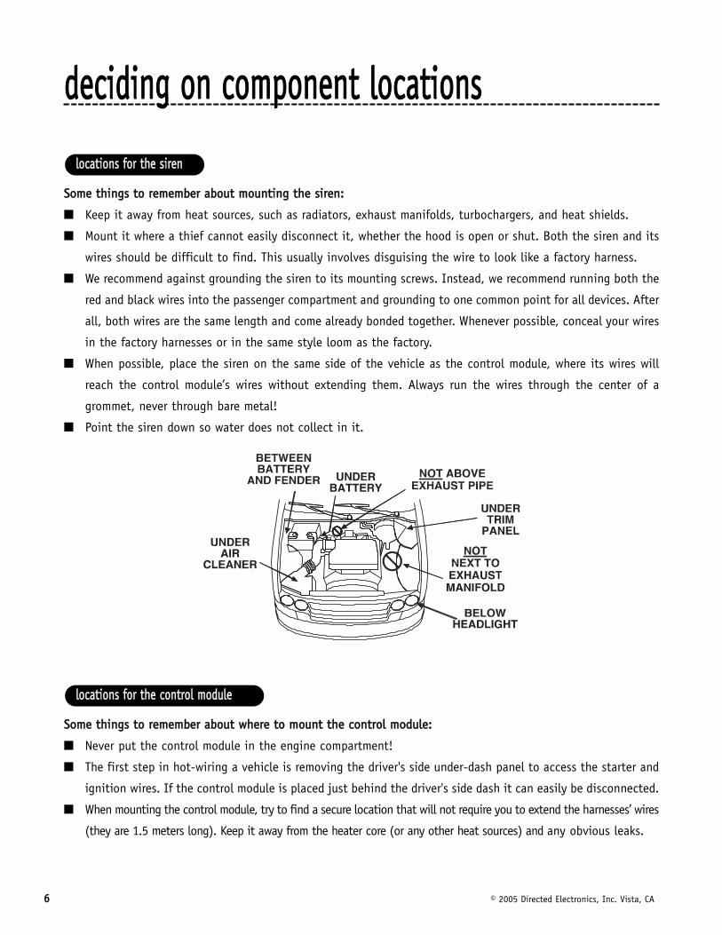
SSoommee tthhiinnggss ttoo rreemmeemmbbeerr aabboouutt mmoouunnttiinngg tthhee ssiirreenn::
■ Keep it away from heat sources, such as radiators, exhaust manifolds, turbochargers, and heat shields.
■ Mount it where a thief cannot easily disconnect it, whether the hood is open or shut. Both the siren and its
wires should be difficult to find. This usually involves disguising the wire to look like a factory harness.
■ We recommend against grounding the siren to its mounting screws. Instead, we recommend running both the
red and black wires into the passenger compartment and grounding to one common point for all devices. After
all, both wires are the same length and come already bonded together. Whenever possible, conceal your wires
in the factory harnesses or in the same style loom as the factory.
■ When possible, place the siren on the same side of the vehicle as the control module, where its wires will
reach the control module’s wires without extending them. Always run the wires through the center of a
grommet, never through bare metal!
■ Point the siren down so water does not collect in it.
SSoommee tthhiinnggss ttoo rreemmeemmbbeerr aabboouutt wwhheerree ttoo mmoouunntt tthhee ccoonnttrrooll mmoodduullee::
■ Never put the control module in the engine compartment!
■ The first step in hot-wiring a vehicle is removing the driver's side under-dash panel to access the starter and
ignition wires. If the control module is placed just behind the driver's side dash it can easily be disconnected.
■ When mounting the control module, try to find a secure location that will not require you to extend the harnesses’ wires
(they are 1.5 meters long). Keep it away from the heater core (or any other heat sources) and any obvious leaks.
llooccaattiioonnss ffoorr tthhee ccoonnttrrooll mmoodduullee
llooccaattiioonnss ffoorr tthhee ssiirreenn
© 2005 Directed Electronics, Inc. Vista, CA 77
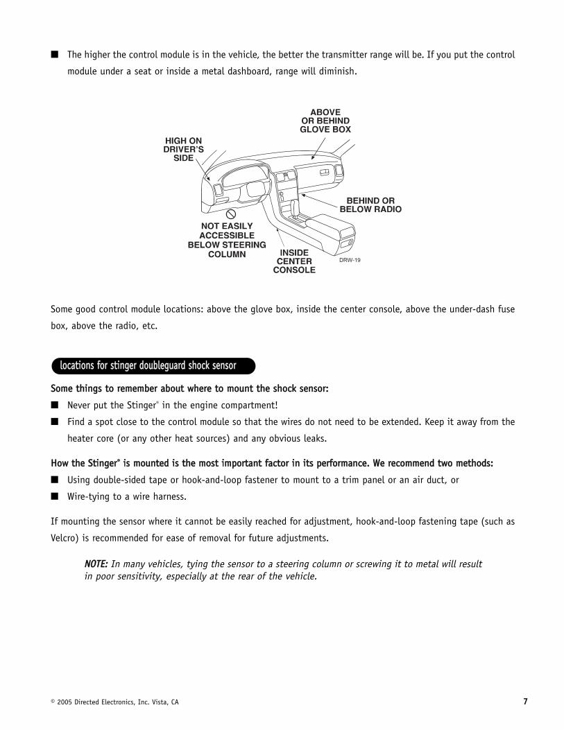
■ The higher the control module is in the vehicle, the better the transmitter range will be. If you put the control
module under a seat or inside a metal dashboard, range will diminish.
Some good control module locations: above the glove box, inside the center console, above the under-dash fuse
box, above the radio, etc.
SSoommee tthhiinnggss ttoo rreemmeemmbbeerr aabboouutt wwhheerree ttoo mmoouunntt tthhee sshhoocckk sseennssoorr::
■ Never put the Stinger® in the engine compartment!
■ Find a spot close to the control module so that the wires do not need to be extended. Keep it away from the
heater core (or any other heat sources) and any obvious leaks.
HHooww tthhee SSttiinnggeerr®® iiss mmoouunntteedd iiss tthhee mmoosstt iimmppoorrttaanntt ffaaccttoorr iinn iittss ppeerrffoorrmmaannccee.. WWee rreeccoommmmeenndd ttwwoo mmeetthhooddss::
■ Using double-sided tape or hook-and-loop fastener to mount to a trim panel or an air duct, or
■ Wire-tying to a wire harness.
If mounting the sensor where it cannot be easily reached for adjustment, hook-and-loop fastening tape (such as
Velcro) is recommended for ease of removal for future adjustments.
NNOOTTEE:: In many vehicles, tying the sensor to a steering column or screwing it to metal will resultin poor sensitivity, especially at the rear of the vehicle.
llooccaattiioonnss ffoorr ssttiinnggeerr ddoouubblleegguuaarrdd sshhoocckk sseennssoorr
88 © 2005 Directed Electronics, Inc. Vista, CA
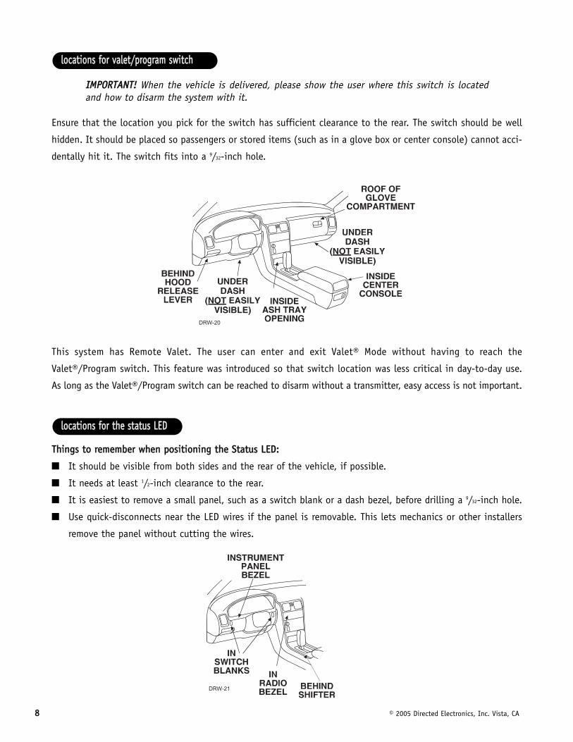
IIMMPPOORRTTAANNTT!! When the vehicle is delivered, please show the user where this switch is locatedand how to disarm the system with it.
Ensure that the location you pick for the switch has sufficient clearance to the rear. The switch should be well
hidden. It should be placed so passengers or stored items (such as in a glove box or center console) cannot acci-
dentally hit it. The switch fits into a 9/32-inch hole.
This system has Remote Valet. The user can enter and exit Valet® Mode without having to reach the
Valet®/Program switch. This feature was introduced so that switch location was less critical in day-to-day use.
As long as the Valet®/Program switch can be reached to disarm without a transmitter, easy access is not important.
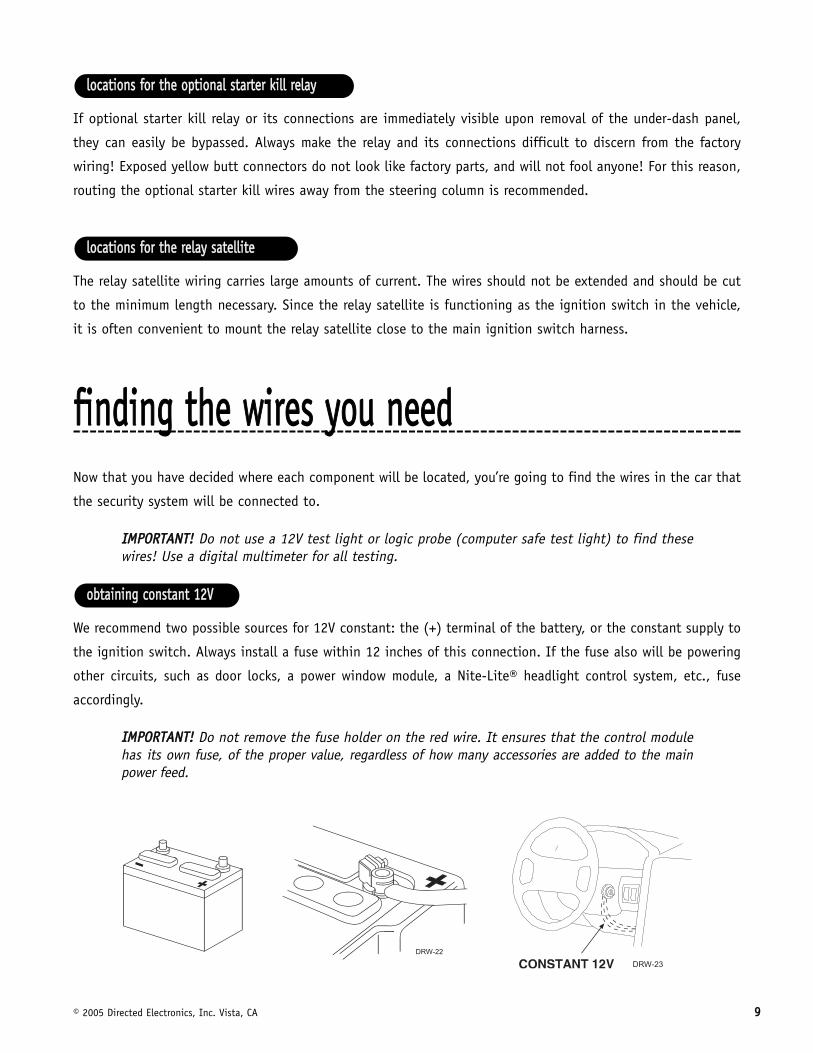
TThhiinnggss ttoo rreemmeemmbbeerr wwhheenn ppoossiittiioonniinngg tthhee SSttaattuuss LLEEDD::
■ It should be visible from both sides and the rear of the vehicle, if possible.
■ It needs at least 1/2-inch clearance to the rear.
■ It is easiest to remove a small panel, such as a switch blank or a dash bezel, before drilling a 9/32-inch hole.
■ Use quick-disconnects near the LED wires if the panel is removable. This lets mechanics or other installers
remove the panel without cutting the wires.
llooccaattiioonnss ffoorr tthhee ssttaattuuss LLEEDD
llooccaattiioonnss ffoorr vvaalleett//pprrooggrraamm sswwiittcchh
© 2005 Directed Electronics, Inc. Vista, CA 99
If optional starter kill relay or its connections are immediately visible upon removal of the under-dash panel,
they can easily be bypassed. Always make the relay and its connections difficult to discern from the factory
wiring! Exposed yellow butt connectors do not look like factory parts, and will not fool anyone! For this reason,
routing the optional starter kill wires away from the steering column is recommended.
The relay satellite wiring carries large amounts of current. The wires should not be extended and should be cut
to the minimum length necessary. Since the relay satellite is functioning as the ignition switch in the vehicle,
it is often convenient to mount the relay satellite close to the main ignition switch harness.
ffiinnddiinngg tthhee wwiirreess yyoouu nneeeeddNow that you have decided where each component will be located, you’re going to find the wires in the car that
the security system will be connected to.
IIMMPPOORRTTAANNTT!! Do not use a 12V test light or logic probe (computer safe test light) to find thesewires! Use a digital multimeter for all testing.
We recommend two possible sources for 12V constant: the (+) terminal of the battery, or the constant supply to
the ignition switch. Always install a fuse within 12 inches of this connection. If the fuse also will be powering
other circuits, such as door locks, a power window module, a Nite-Lite® headlight control system, etc., fuse
accordingly.
IIMMPPOORRTTAANNTT!! Do not remove the fuse holder on the red wire. It ensures that the control modulehas its own fuse, of the proper value, regardless of how many accessories are added to the mainpower feed.
oobbttaaiinniinngg ccoonnssttaanntt 1122VV
llooccaattiioonnss ffoorr tthhee rreellaayy ssaatteelllliittee
llooccaattiioonnss ffoorr tthhee ooppttiioonnaall ssttaarrtteerr kkiillll rreellaayy
1100 © 2005 Directed Electronics, Inc. Vista, CA
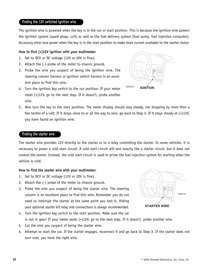
The ignition wire is powered when the key is in the run or start position. This is because the ignition wire powers
the ignition system (spark plugs, coil) as well as the fuel delivery system (fuel pump, fuel injection computer).
Accessory wires lose power when the key is in the start position to make more current available to the starter motor.
HHooww ttoo ffiinndd ((++))1122VV iiggnniittiioonn wwiitthh yyoouurr mmuullttiimmeetteerr::
1. Set to DCV or DC voltage (12V or 20V is fine).
2. Attach the (-) probe of the meter to chassis ground.
3. Probe the wire you suspect of being the ignition wire. The
steering column harness or ignition switch harness is an excel-
lent place to find this wire.
4. Turn the ignition key switch to the run position. If your meter
reads (+)12V, go to the next step. If it doesn’t, probe another
wire.
5. Now turn the key to the start position. The meter display should stay steady, not dropping by more than a
few tenths of a volt. If it drops close to or all the way to zero, go back to Step 3. If it stays steady at (+)12V,
you have found an ignition wire.
The starter wire provides 12V directly to the starter or to a relay controlling the starter. In some vehicles, it is
necessary to power a cold start circuit. A cold start circuit will test exactly like a starter circuit, but it does not
control the starter. Instead, the cold start circuit is used to prime the fuel injection system for starting when the
vehicle is cold.
HHooww ttoo ffiinndd tthhee ssttaarrtteerr wwiirree wwiitthh yyoouurr mmuullttiimmeetteerr::
1. Set to DCV or DC voltage (12V or 20V is fine).
2. Attach the (-) probe of the meter to chassis ground.
3. Probe the wire you suspect of being the starter wire. The steering
column is an excellent place to find this wire. Remember you do not
need to interrupt the starter at the same point you test it. Hiding
your optional starter kill relay and connections is always recommended.
4. Turn the ignition key switch to the start position. Make sure the car
is not in gear! If your meter reads (+)12V, go to the next step. If it doesn’t, probe another wire.
5. Cut the wire you suspect of being the starter wire.
6. Attempt to start the car. If the starter engages, reconnect it and go back to Step 3. If the starter does not
turn over, you have the right wire.
ffiinnddiinngg tthhee ssttaarrtteerr wwiirree
ffiinnddiinngg tthhee 1122VV sswwiittcchheedd iiggnniittiioonn wwiirree
© 2005 Directed Electronics, Inc. Vista, CA 1111
An accessory wire will show +12V when the key is in the accessory and run positions. It will not show +12V during
the cranking cycle. There will often be more than one accessory wire in the ignition harness. The correct accessory
wire will power the vehicle's climate control system. Some vehicles may have separate wires for the blower motor and
the air conditioning compressor. In such cases, it will be necessary to add a relay to power the second accessory wire.
To test for a tachometer wire, a multimeter capable of testing AC voltage must be used. The tachometer wire will
show between 1V and 6V AC. In multi-coil ignition systems, the system can learn individual coil wires. Individual
coil wires in a multi-coil ignition system will register lower amounts of AC voltage. Also, if necessary, the system
can use a fuel injector control wire for engine speed sensing. Common locations for a tachometer wire are the
ignition coil itself, the back of the gauges, engine computers, and automatic transmission computers.
IIMMPPOORRTTAANNTT!! Do not test tachometer wires using a test light or logic probe (computer safe test light)!This will damage the vehicle.
HHooww ttoo ffiinndd aa ttaacchhoommeetteerr wwiirree wwiitthh yyoouurr mmuullttiimmeetteerr::
1. Set to ACV or AC voltage (12V or 20V is fine).
2. Attach the (-) probe of the meter to chassis ground.
3. Start and run the vehicle.
4. Probe the wire you suspect of being the tachometer wire with the red probe of the meter.
5. If this is the correct wire the meter will read between 1V and 6V.
In diesel vehicles it is necessary to interface with the wire that turns on the WAIT TO START light in the dash-
board. This wire illuminates the bulb until the vehicle’s glow plugs are properly heated. When the light goes out
the vehicle can be started. This wire is always available at the connector leading to the bulb in the dashboard.
It can also be found at the Engine Control Module (ECM) in many vehicles.
TToo tteesstt aanndd ddeetteerrmmiinnee tthhee ppoollaarriittyy ooff tthhiiss wwiirree::
1. Set your multimeter to DCV or DC voltage (12 or 20V is fine).
2. Attach the (+) probe of the meter to (+)12V.
3. Probe the wire that you suspect leads to the bulb with the (-) probe of the meter.
4. Turn the ignition switch to the ON position.
5. If the meter indicates 12 volts until the light goes out you have isolated the correct wire and the wire's polar-
ity is negative (ground while the bulb is on).
6. If the meter reads zero volts until the light goes out and then reads 12 volts, you have isolated the correct
wire and the wire's polarity is positive.
ffiinnddiinngg tthhee wwaaiitt--ttoo--ssttaarrtt bbuullbb wwiirree ffoorr ddiieesseellss
ffiinnddiinngg tthhee ttaacchhoommeetteerr wwiirree
ffiinnddiinngg tthhee aacccceessssoorryy wwiirree
1122 © 2005 Directed Electronics, Inc. Vista, CA
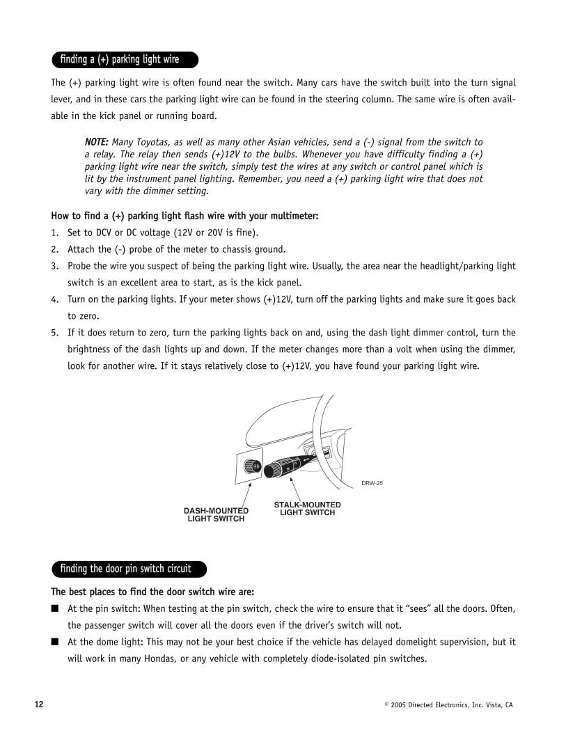
The (+) parking light wire is often found near the switch. Many cars have the switch built into the turn signal
lever, and in these cars the parking light wire can be found in the steering column. The same wire is often avail-
able in the kick panel or running board.
NNOOTTEE:: Many Toyotas, as well as many other Asian vehicles, send a (-) signal from the switch toa relay. The relay then sends (+)12V to the bulbs. Whenever you have difficulty finding a (+)parking light wire near the switch, simply test the wires at any switch or control panel which islit by the instrument panel lighting. Remember, you need a (+) parking light wire that does notvary with the dimmer setting.
HHooww ttoo ffiinndd aa ((++)) ppaarrkkiinngg lliigghhtt ffllaasshh wwiirree wwiitthh yyoouurr mmuullttiimmeetteerr::
1. Set to DCV or DC voltage (12V or 20V is fine).
2. Attach the (-) probe of the meter to chassis ground.
3. Probe the wire you suspect of being the parking light wire. Usually, the area near the headlight/parking light
switch is an excellent area to start, as is the kick panel.
4. Turn on the parking lights. If your meter shows (+)12V, turn off the parking lights and make sure it goes back
to zero.
5. If it does return to zero, turn the parking lights back on and, using the dash light dimmer control, turn the
brightness of the dash lights up and down. If the meter changes more than a volt when using the dimmer,
look for another wire. If it stays relatively close to (+)12V, you have found your parking light wire.
TThhee bbeesstt ppllaacceess ttoo ffiinndd tthhee ddoooorr sswwiittcchh wwiirree aarree::
■ At the pin switch: When testing at the pin switch, check the wire to ensure that it “sees” all the doors. Often,
the passenger switch will cover all the doors even if the driver’s switch will not.
■ At the dome light: This may not be your best choice if the vehicle has delayed domelight supervision, but it
will work in many Hondas, or any vehicle with completely diode-isolated pin switches.
ffiinnddiinngg tthhee ddoooorr ppiinn sswwiittcchh cciirrccuuiitt
ffiinnddiinngg aa ((++)) ppaarrkkiinngg lliigghhtt wwiirree
© 2005 Directed Electronics, Inc. Vista, CA 1133
Once you have determined the wire color, the easiest place to connect to the wire is often at the kick panel, at
the windshield pillar, or in the running board. When an easy location is not available, running a wire to the dome-
light itself is often the best solution.
HHooww ttoo ffiinndd aa ddoooorr ppiinn sswwiittcchh ttrriiggggeerr wwiirree wwiitthh yyoouurr mmuullttiimmeetteerr::
1. Set to DCV or DC voltage (12V or 20V is fine).
2. In most Fords, fasten the (-) probe of the meter to chassis ground. In most other cars, fasten the (+) probe
of your meter to (+)12V constant.
3. Probe the wire you suspect of being the door trigger wire. If the meter reads (+)12V when any door
is opened, you have found a trigger wire.
NNOOTTEE:: Make sure the wire you use “sees” all the doors! Some newer GM vehicles lack standard-type pin switches. The dome light in these vehicles is turned on when the door handle is lifted.These usually have a blue/white or white wire coming out of the door into the kick panel whichwill provide a (-) trigger for all doors. Some GM vehicles (some Cavaliers, Grand Ams, etc.) havea yellow wire coming out of the door which provides a (+) door trigger.
mmaakkiinngg yyoouurr wwiirriinngg ccoonnnneeccttiioonnssBefore making your connections, plan how your wires will be routed through the vehicle. For instance, the red
12V constant input and the orange ground-when-armed output (for the optional starter kill relay) will often be
routed together to the ignition switch harness. In order to keep the wiring neat and make it harder to find, you
may wish to wrap these wires together in electrical tape or conceal them in tubing similar to what the manu-
facturer used.
There are two acceptable ways of making a wire connection - solder connections and crimp connectors. When
properly performed, either type of connection is reliable and trouble-free. Regardless of whether you solder your
connections or you use mechanical-type crimp-on connections, ensure that all connections are mechanically
sound and that they are insulated.
Cheap electrical tape, especially when poorly applied, is not a reliable insulator. It often falls off in hot weather.
Use good-quality electrical tape or heat shrink.
■ Never twist-and-tape the wires together without soldering.
■ Never use “fuse taps”, as they can damage fuse box terminals.
If you use tapping connectors such as 3M T-Taps (not to be confused with Scotch-Locks), avoid using them in
higher-current applications (constant 12V, ground, etc.). Some tapping connectors are inferior in quality and
should be avoided.
1144 © 2005 Directed Electronics, Inc. Vista, CA
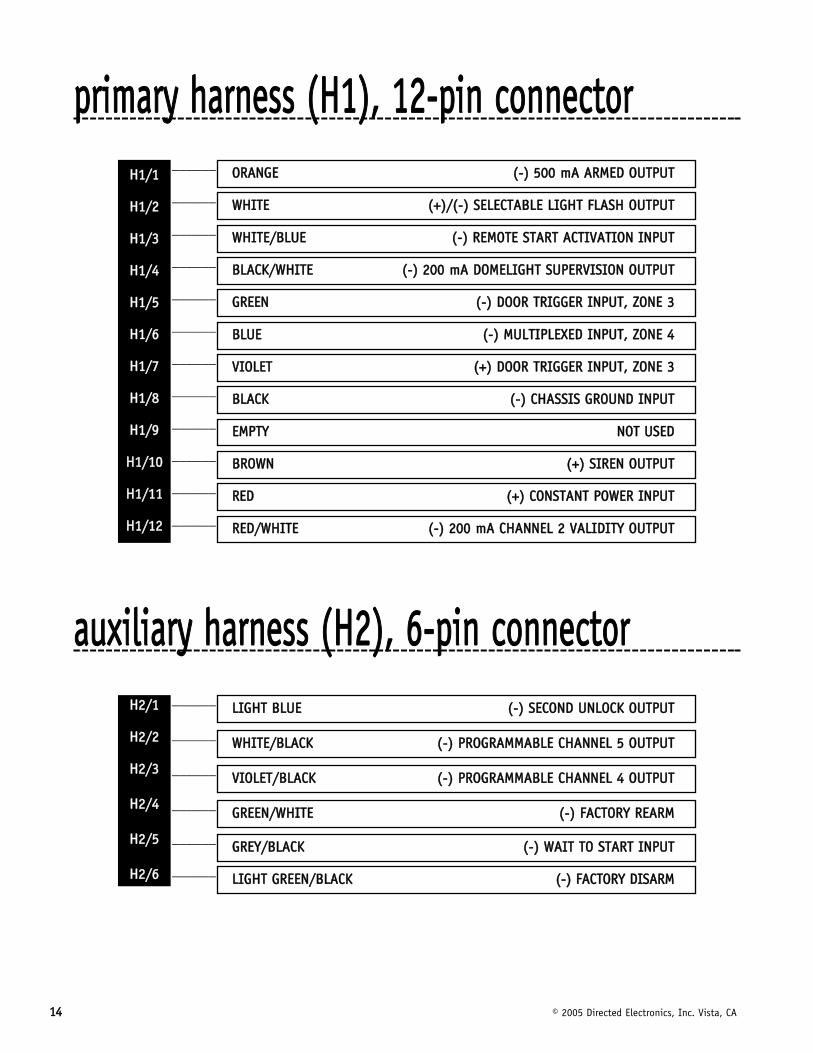
pprriimmaarryy hhaarrnneessss ((HH11)),, 1122--ppiinn ccoonnnneeccttoorr______
______
______
______
______
______
______
______
______
______
______
______
aauuxxiilliiaarryy hhaarrnneessss ((HH22)),, 66--ppiinn ccoonnnneeccttoorr______
______
______
______
______
______ LLIIGGHHTT GGRREEEENN//BBLLAACCKK ((--)) FFAACCTTOORRYY DDIISSAARRMM
GGRREEYY//BBLLAACCKK ((--)) WWAAIITT TTOO SSTTAARRTT IINNPPUUTT
GGRREEEENN//WWHHIITTEE ((--)) FFAACCTTOORRYY RREEAARRMM
VVIIOOLLEETT//BBLLAACCKK ((--)) PPRROOGGRRAAMMMMAABBLLEE CCHHAANNNNEELL 44 OOUUTTPPUUTT
WWHHIITTEE//BBLLAACCKK ((--)) PPRROOGGRRAAMMMMAABBLLEE CCHHAANNNNEELL 55 OOUUTTPPUUTT
LLIIGGHHTT BBLLUUEE ((--)) SSEECCOONNDD UUNNLLOOCCKK OOUUTTPPUUTTHH22//11
HH22//22
HH22//33
HH22//44
HH22//55
HH22//66
RREEDD//WWHHIITTEE ((--)) 220000 mmAA CCHHAANNNNEELL 22 VVAALLIIDDIITTYY OOUUTTPPUUTT
RREEDD ((++)) CCOONNSSTTAANNTT PPOOWWEERR IINNPPUUTT
BBRROOWWNN ((++)) SSIIRREENN OOUUTTPPUUTT
EEMMPPTTYY NNOOTT UUSSEEDD
BBLLAACCKK ((--)) CCHHAASSSSIISS GGRROOUUNNDD IINNPPUUTT
VVIIOOLLEETT ((++)) DDOOOORR TTRRIIGGGGEERR IINNPPUUTT,, ZZOONNEE 33
BBLLUUEE ((--)) MMUULLTTIIPPLLEEXXEEDD IINNPPUUTT,, ZZOONNEE 44
GGRREEEENN ((--)) DDOOOORR TTRRIIGGGGEERR IINNPPUUTT,, ZZOONNEE 33
BBLLAACCKK//WWHHIITTEE ((--)) 220000 mmAA DDOOMMEELLIIGGHHTT SSUUPPEERRVVIISSIIOONN OOUUTTPPUUTT
WWHHIITTEE//BBLLUUEE ((--)) RREEMMOOTTEE SSTTAARRTT AACCTTIIVVAATTIIOONN IINNPPUUTT
WWHHIITTEE ((++))//((--)) SSEELLEECCTTAABBLLEE LLIIGGHHTT FFLLAASSHH OOUUTTPPUUTT
OORRAANNGGEE ((--)) 550000 mmAA AARRMMEEDD OOUUTTPPUUTT HH11//11
HH11//22
HH11//33
HH11//44
HH11//55
HH11//66
HH11//77
HH11//88
HH11//99
HH11//1100
HH11//1111
HH11//1122
© 2005 Directed Electronics, Inc. Vista, CA 1155
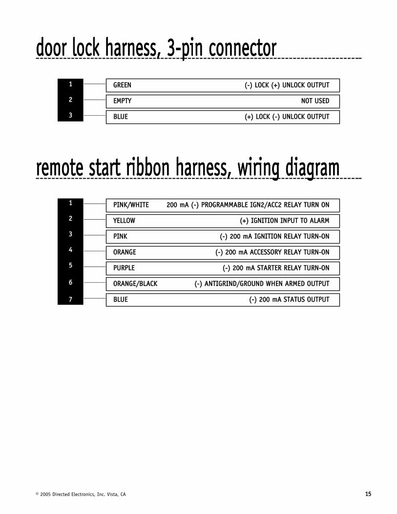
ddoooorr lloocckk hhaarrnneessss,, 33--ppiinn ccoonnnneeccttoorr______
______
______
rreemmoottee ssttaarrtt rriibbbboonn hhaarrnneessss,, wwiirriinngg ddiiaaggrraamm______
______
______
______
______
______
______ BBLLUUEE ((--)) 220000 mmAA SSTTAATTUUSS OOUUTTPPUUTT
OORRAANNGGEE//BBLLAACCKK ((--)) AANNTTIIGGRRIINNDD//GGRROOUUNNDD WWHHEENN AARRMMEEDD OOUUTTPPUUTT
PPUURRPPLLEE ((--)) 220000 mmAA SSTTAARRTTEERR RREELLAAYY TTUURRNN--OONN
OORRAANNGGEE ((--)) 220000 mmAA AACCCCEESSSSOORRYY RREELLAAYY TTUURRNN--OONN
PPIINNKK ((--)) 220000 mmAA IIGGNNIITTIIOONN RREELLAAYY TTUURRNN--OONN
YYEELLLLOOWW ((++)) IIGGNNIITTIIOONN IINNPPUUTT TTOO AALLAARRMM
PPIINNKK//WWHHIITTEE 220000 mmAA ((--)) PPRROOGGRRAAMMMMAABBLLEE IIGGNN22//AACCCC22 RREELLAAYY TTUURRNN OONN11
22
33
44
55
66
77
BBLLUUEE ((++)) LLOOCCKK ((--)) UUNNLLOOCCKK OOUUTTPPUUTT
EEMMPPTTYY NNOOTT UUSSEEDD
GGRREEEENN ((--)) LLOOCCKK ((++)) UUNNLLOOCCKK OOUUTTPPUUTT11
22
33
1166 © 2005 Directed Electronics, Inc. Vista, CA
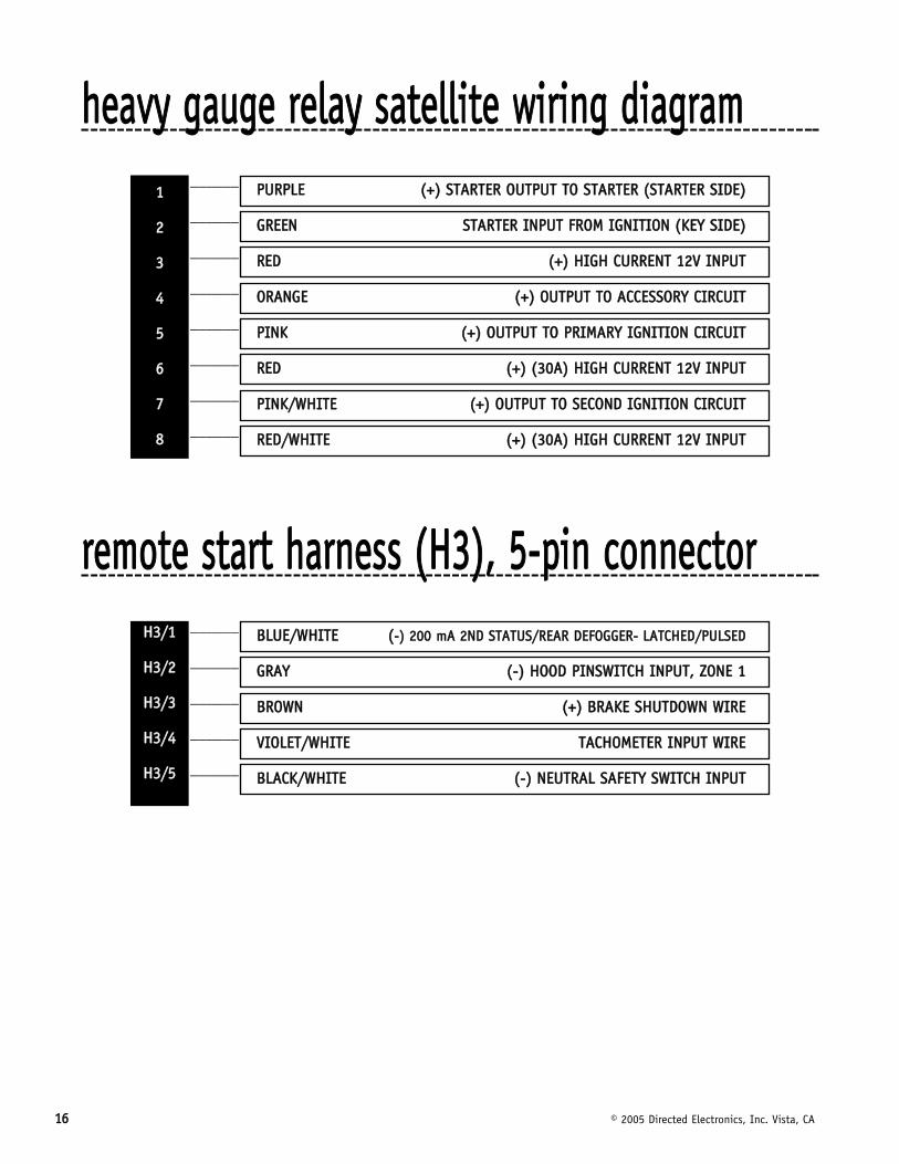
hheeaavvyy ggaauuggee rreellaayy ssaatteelllliittee wwiirriinngg ddiiaaggrraamm______
______
______
______
______
______
______
______
rreemmoottee ssttaarrtt hhaarrnneessss ((HH33)),, 55--ppiinn ccoonnnneeccttoorr______
______
______
______
______ BBLLAACCKK//WWHHIITTEE ((--)) NNEEUUTTRRAALL SSAAFFEETTYY SSWWIITTCCHH IINNPPUUTT
VVIIOOLLEETT//WWHHIITTEE TTAACCHHOOMMEETTEERR IINNPPUUTT WWIIRREE
BBRROOWWNN ((++)) BBRRAAKKEE SSHHUUTTDDOOWWNN WWIIRREE
GGRRAAYY ((--)) HHOOOODD PPIINNSSWWIITTCCHH IINNPPUUTT,, ZZOONNEE 11
BBLLUUEE//WWHHIITTEE ((--)) 220000 mmAA 22NNDD SSTTAATTUUSS//RREEAARR DDEEFFOOGGGGEERR-- LLAATTCCHHEEDD//PPUULLSSEEDDHH33//11
HH33//22
HH33//33
HH33//44
HH33//55
RREEDD//WWHHIITTEE ((++)) ((3300AA)) HHIIGGHH CCUURRRREENNTT 1122VV IINNPPUUTT
PPIINNKK//WWHHIITTEE ((++)) OOUUTTPPUUTT TTOO SSEECCOONNDD IIGGNNIITTIIOONN CCIIRRCCUUIITT
RREEDD ((++)) ((3300AA)) HHIIGGHH CCUURRRREENNTT 1122VV IINNPPUUTT
PPIINNKK ((++)) OOUUTTPPUUTT TTOO PPRRIIMMAARRYY IIGGNNIITTIIOONN CCIIRRCCUUIITT
OORRAANNGGEE ((++)) OOUUTTPPUUTT TTOO AACCCCEESSSSOORRYY CCIIRRCCUUIITT
RREEDD ((++)) HHIIGGHH CCUURRRREENNTT 1122VV IINNPPUUTT
GGRREEEENN SSTTAARRTTEERR IINNPPUUTT FFRROOMM IIGGNNIITTIIOONN ((KKEEYY SSIIDDEE))
PPUURRPPLLEE ((++)) SSTTAARRTTEERR OOUUTTPPUUTT TTOO SSTTAARRTTEERR ((SSTTAARRTTEERR SSIIDDEE))11
22
33
44
55
66
77
88
© 2005 Directed Electronics, Inc. Vista, CA 1177
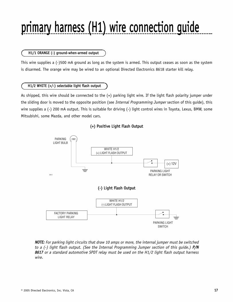
pprriimmaarryy hhaarrnneessss ((HH11)) wwiirree ccoonnnneeccttiioonn gguuiiddee
This wire supplies a (-)500 mA ground as long as the system is armed. This output ceases as soon as the system
is disarmed. The orange wire may be wired to an optional Directed Electronics 8618 starter kill relay.
As shipped, this wire should be connected to the (+) parking light wire. If the light flash polarity jumper under
the sliding door is moved to the opposite position (see Internal Programming Jumper section of this guide), this
wire supplies a (-) 200 mA output. This is suitable for driving (-) light control wires in Toyota, Lexus, BMW, some
Mitsubishi, some Mazda, and other model cars.
((++)) PPoossiittiivvee LLiigghhtt FFllaasshh OOuuttppuutt
((--)) LLiigghhtt FFllaasshh OOuuttppuutt
NNOOTTEE:: For parking light circuits that draw 10 amps or more, the internal jumper must be switchedto a (-) light flash output. (See the Internal Programming Jumper section of this guide.) PP//NN88661177 or a standard automotive SPDT relay must be used on the H1/2 light flash output harnesswire.
HH11//22 WWHHIITTEE ((++//--)) sseelleeccttaabbllee lliigghhtt ffllaasshh oouuttppuutt
HH11//11 OORRAANNGGEE ((--)) ggrroouunndd--wwhheenn--aarrmmeedd oouuttppuutt
1188 © 2005 Directed Electronics, Inc. Vista, CA
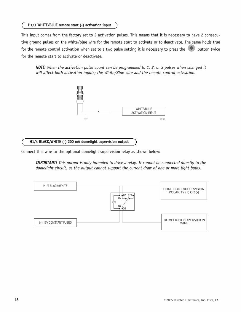
This input comes from the factory set to 2 activation pulses. This means that it is necessary to have 2 consecu-
tive ground pulses on the white/blue wire for the remote start to activate or to deactivate. The same holds true
for the remote control activation when set to a two pulse setting it is necessary to press the button twice
for the remote start to activate or deactivate.
NNOOTTEE:: When the activation pulse count can be programmed to 1, 2, or 3 pulses when changed itwill affect both activation inputs; the White/Blue wire and the remote control activation.
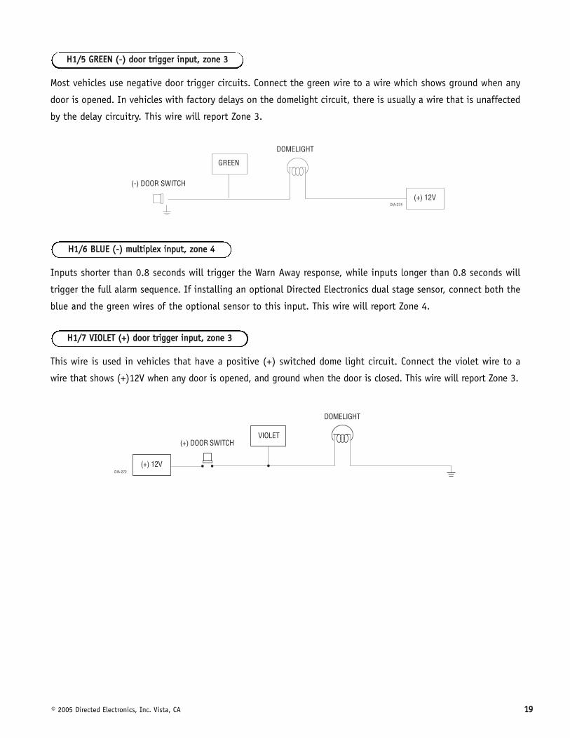
Connect this wire to the optional domelight supervision relay as shown below:
IIMMPPOORRTTAANNTT!! This output is only intended to drive a relay. It cannot be connected directly to thedomelight circuit, as the output cannot support the current draw of one or more light bulbs.
HH11//44 BBLLAACCKK//WWHHIITTEE ((--)) 220000 mmAA ddoommeelliigghhtt ssuuppeerrvviissiioonn oouuttppuutt
HH11//33 WWHHIITTEE//BBLLUUEE rreemmoottee ssttaarrtt ((--)) aaccttiivvaattiioonn iinnppuutt
© 2005 Directed Electronics, Inc. Vista, CA 1199
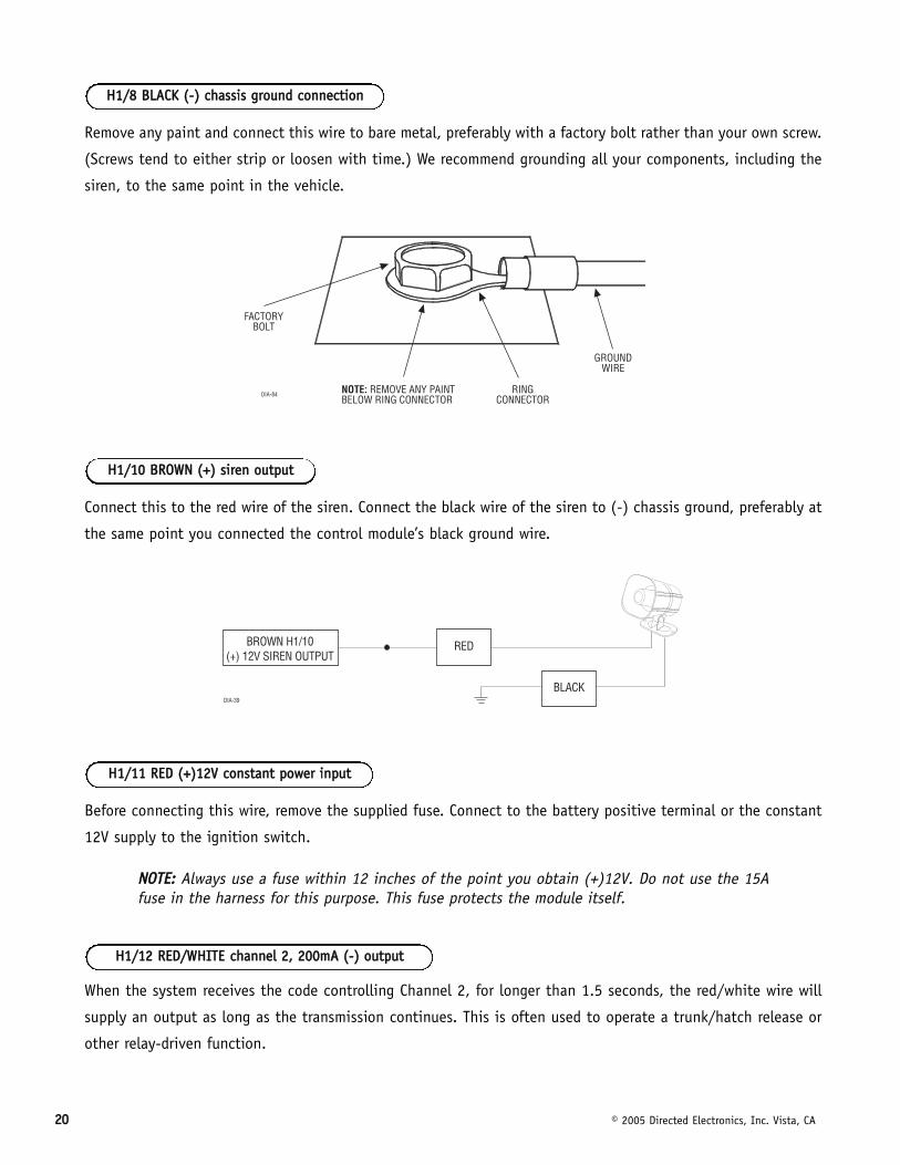
Most vehicles use negative door trigger circuits. Connect the green wire to a wire which shows ground when any
door is opened. In vehicles with factory delays on the domelight circuit, there is usually a wire that is unaffected
by the delay circuitry. This wire will report Zone 3.
Inputs shorter than 0.8 seconds will trigger the Warn Away response, while inputs longer than 0.8 seconds will
trigger the full alarm sequence. If installing an optional Directed Electronics dual stage sensor, connect both the
blue and the green wires of the optional sensor to this input. This wire will report Zone 4.
This wire is used in vehicles that have a positive (+) switched dome light circuit. Connect the violet wire to a
wire that shows (+)12V when any door is opened, and ground when the door is closed. This wire will report Zone 3.
HH11//77 VVIIOOLLEETT ((++)) ddoooorr ttrriiggggeerr iinnppuutt,, zzoonnee 33
HH11//66 BBLLUUEE ((--)) mmuullttiipplleexx iinnppuutt,, zzoonnee 44
HH11//55 GGRREEEENN ((--)) ddoooorr ttrriiggggeerr iinnppuutt,, zzoonnee 33
2200 © 2005 Directed Electronics, Inc. Vista, CA
Remove any paint and connect this wire to bare metal, preferably with a factory bolt rather than your own screw.
(Screws tend to either strip or loosen with time.) We recommend grounding all your components, including the
siren, to the same point in the vehicle.
Connect this to the red wire of the siren. Connect the black wire of the siren to (-) chassis ground, preferably at
the same point you connected the control module’s black ground wire.
Before connecting this wire, remove the supplied fuse. Connect to the battery positive terminal or the constant
12V supply to the ignition switch.
NNOOTTEE:: Always use a fuse within 12 inches of the point you obtain (+)12V. Do not use the 15Afuse in the harness for this purpose. This fuse protects the module itself.
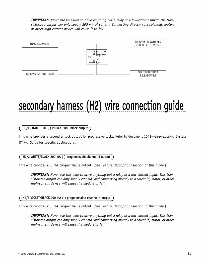
When the system receives the code controlling Channel 2, for longer than 1.5 seconds, the red/white wire will
supply an output as long as the transmission continues. This is often used to operate a trunk/hatch release or
other relay-driven function.
HH11//1122 RREEDD//WWHHIITTEE cchhaannnneell 22,, 220000mmAA ((--)) oouuttppuutt
HH11//1111 RREEDD ((++))1122VV ccoonnssttaanntt ppoowweerr iinnppuutt
HH11//1100 BBRROOWWNN ((++)) ssiirreenn oouuttppuutt
HH11//88 BBLLAACCKK ((--)) cchhaassssiiss ggrroouunndd ccoonnnneeccttiioonn
© 2005 Directed Electronics, Inc. Vista, CA 2211
IIMMPPOORRTTAANNTT!! Never use this wire to drive anything but a relay or a low-current input! The tran-sistorized output can only supply 200 mA of current. Connecting directly to a solenoid, motor,or other high-current device will cause it to fail.
sseeccoonnddaarryy hhaarrnneessss ((HH22)) wwiirree ccoonnnneeccttiioonn gguuiiddee
This wire provides a second unlock output for progressive locks. Refer to document 1041—Door Locking System
Wiring Guide for specific applications.
This wire provides 200 mA programmable output. (See Feature Descriptions section of this guide.)
IIMMPPOORRTTAANNTT!! Never use this wire to drive anything but a relay or a low-current input! This tran-sistorized output can only supply 200 mA, and connecting directly to a solenoid, motor, or otherhigh-current device will cause the module to fail.
HH22//33 VVIIOOLLEETT//BBLLAACCKK 220000 mmAA ((--)) pprrooggrraammmmaabbllee cchhaannnneell 44 oouuttppuutt
HH22//22 WWHHIITTEE//BBLLAACCKK 220000 mmAA ((--)) pprrooggrraammmmaabbllee cchhaannnneell 55 oouuttppuutt
HH22//11 LLIIGGHHTT BBLLUUEE ((--)) 220000mmAA 22nndd uunnlloocckk oouuttppuutt
2222 © 2005 Directed Electronics, Inc. Vista, CA
This wire sends a negative pulse every time the remote start shuts down or the doors are locked. This can be used to
pulse the arm wire of the vehicle's factory anti-theft device. Use a relay to send a (-) or (+) pulse to the arm wire.
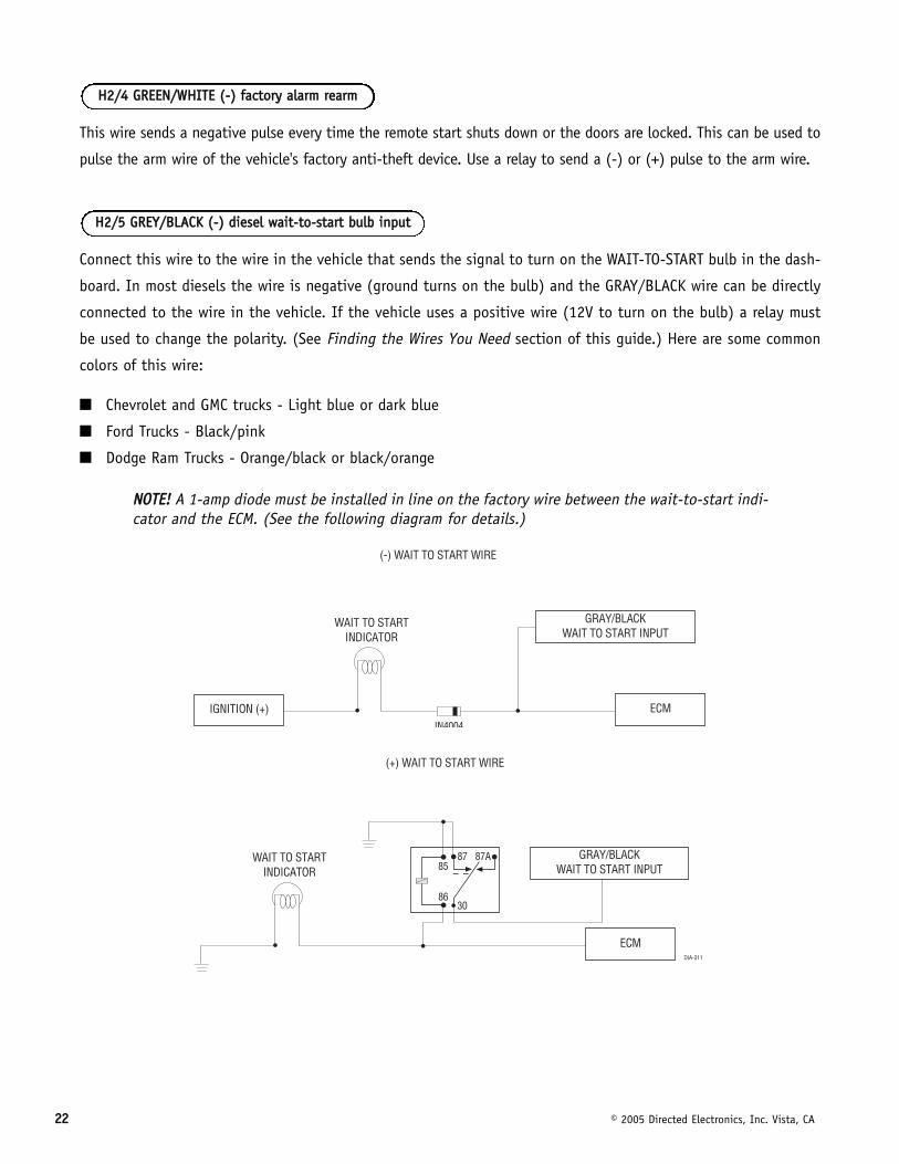
Connect this wire to the wire in the vehicle that sends the signal to turn on the WAIT-TO-START bulb in the dash-
board. In most diesels the wire is negative (ground turns on the bulb) and the GRAY/BLACK wire can be directly
connected to the wire in the vehicle. If the vehicle uses a positive wire (12V to turn on the bulb) a relay must
be used to change the polarity. (See Finding the Wires You Need section of this guide.) Here are some common
colors of this wire:
■ Chevrolet and GMC trucks - Light blue or dark blue
■ Ford Trucks - Black/pink
■ Dodge Ram Trucks - Orange/black or black/orange
NNOOTTEE!! A 1-amp diode must be installed in line on the factory wire between the wait-to-start indi-cator and the ECM. (See the following diagram for details.)
HH22//55 GGRREEYY//BBLLAACCKK ((--)) ddiieesseell wwaaiitt--ttoo--ssttaarrtt bbuullbb iinnppuutt
HH22//44 GGRREEEENN//WWHHIITTEE ((--)) ffaaccttoorryy aallaarrmm rreeaarrmm
© 2005 Directed Electronics, Inc. Vista, CA 2233
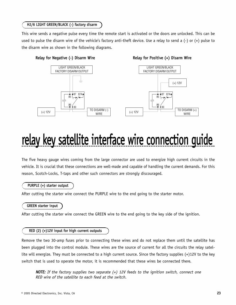
This wire sends a negative pulse every time the remote start is activated or the doors are unlocked. This can be
used to pulse the disarm wire of the vehicle's factory anti-theft device. Use a relay to send a (-) or (+) pulse to
the disarm wire as shown in the following diagrams.
RReellaayy ffoorr NNeeggaattiivvee ((--)) DDiissaarrmm WWiirree RReellaayy ffoorr PPoossiittiivvee ((++)) DDiissaarrmm WWiirree
rreellaayy kkeeyy ssaatteelllliittee iinntteerrffaaccee wwiirree ccoonnnneeccttiioonn gguuiiddeeThe five heavy gauge wires coming from the large connector are used to energize high current circuits in the
vehicle. It is crucial that these connections are well-made and capable of handling the current demands. For this
reason, Scotch-Locks, T-taps and other such connectors are strongly discouraged.
After cutting the starter wire connect the PURPLE wire to the end going to the starter motor.
After cutting the starter wire connect the GREEN wire to the end going to the key side of the ignition.
Remove the two 30-amp fuses prior to connecting these wires and do not replace them until the satellite has
been plugged into the control module. These wires are the source of current for all the circuits the relay satel-
lite will energize. They must be connected to a high current source. Since the factory supplies (+)12V to the key
switch that is used to operate the motor, it is recommended that these wires be connected there.
NNOOTTEE:: If the factory supplies two separate (+) 12V feeds to the ignition switch, connect oneRED wire of the satellite to each feed at the switch.
RREEDD ((22)) ((++))1122VV iinnppuutt ffoorr hhiigghh ccuurrrreenntt oouuttppuuttss
GGRREEEENN ssttaarrtteerr iinnppuutt
PPUURRPPLLEE ((++)) ssttaarrtteerr oouuttppuutt
HH22//66 LLIIGGHHTT GGRREEEENN//BBLLAACCKK ((--)) ffaaccttoorryy ddiissaarrmm
2244 © 2005 Directed Electronics, Inc. Vista, CA
Connect this wire to the accessory wire in the vehicle which powers the climate control system.
Connect this wire to the ignition wire in the vehicle.
Connect this wire to the second ignition/accessory wire in the vehicle. (See selectable menu feature 2-9.)
NNOOTTEE:: For vehicles that do not have a second ignition/accessory wire, this connection is notrequired.
If additional current capacity is needed cut this wire, add a fuse adequate for the circuit to be supplied, and
connect to an additional 12V source.
RREEDD//WWHHIITTEE ((++)) 1122VV iinnppuutt
PPIINNKK//WWHHIITTEE ((++)) sseeccoonndd iiggnniittiioonn aacccceessssoorryy oouuttppuutt
PPIINNKK ((++)) iiggnniittiioonn oouuttppuutt
OORRAANNGGEE ((++)) aacccceessssoorryy oouuttppuutt
© 2005 Directed Electronics, Inc. Vista, CA 2255
rreemmoottee ssttaarrtt sseeccoonnddaarryy hhaarrnneessss ((HH33)) wwiirree ccoonn--nneeccttiioonn gguuiiddee
This wire supplies a 200mA output as soon as the module begins the remote start process. The H3/1 BLUE wire
can also be used to activate the defogger trigger (latched/pulsed) 10-seconds after the remote start engages.
(See the Feature Descriptions section in this guide for details about programming this output.)
This wire MUST be connected to hood pinswitch. This input will disable or shut down the remote start when the hood
is opened. It will also trigger the security system if the hood is opened while the system is armed and report Zone 1.
This wire MUST be connected to the vehicle's brake light wire. This is the wire that shows (+) 12V when the brake
pedal is depressed. The remote start will be disabled or shut down any time the brake pedal is depressed. This
wire will also trigger the security system if the brake pedal is pressed while the system is armed and will report
Zone 1.
This input provides the module with information about the engine's revolutions per minute (RPMs). It can be
connected to the negative side of the coil in vehicles with conventional coils. In multi-coil and high energy igni-
tion systems locating a proper signal may be more difficult. (See Finding the Wires You Need section of this
guide.) Once connected, you must teach the system the tach signal. (See the Internal Programming Jumpers
section of this guide.)
HH33//44 VVIIOOLLEETT//WWHHIITTEE ttaacchhoommeetteerr iinnppuutt
HH33//33 BBRROOWWNN ((++)) bbrraakkee sswwiittcchh iinnppuutt,, zzoonnee 11
HH33//22 GGRRAAYY ((--)) hhoooodd ppiinnsswwiittcchh iinnppuutt,, zzoonnee 11
HH33//11 BBLLUUEE//WWHHIITTEE ((--)) ssttaattuuss oouuttppuutt
2266 © 2005 Directed Electronics, Inc. Vista, CA
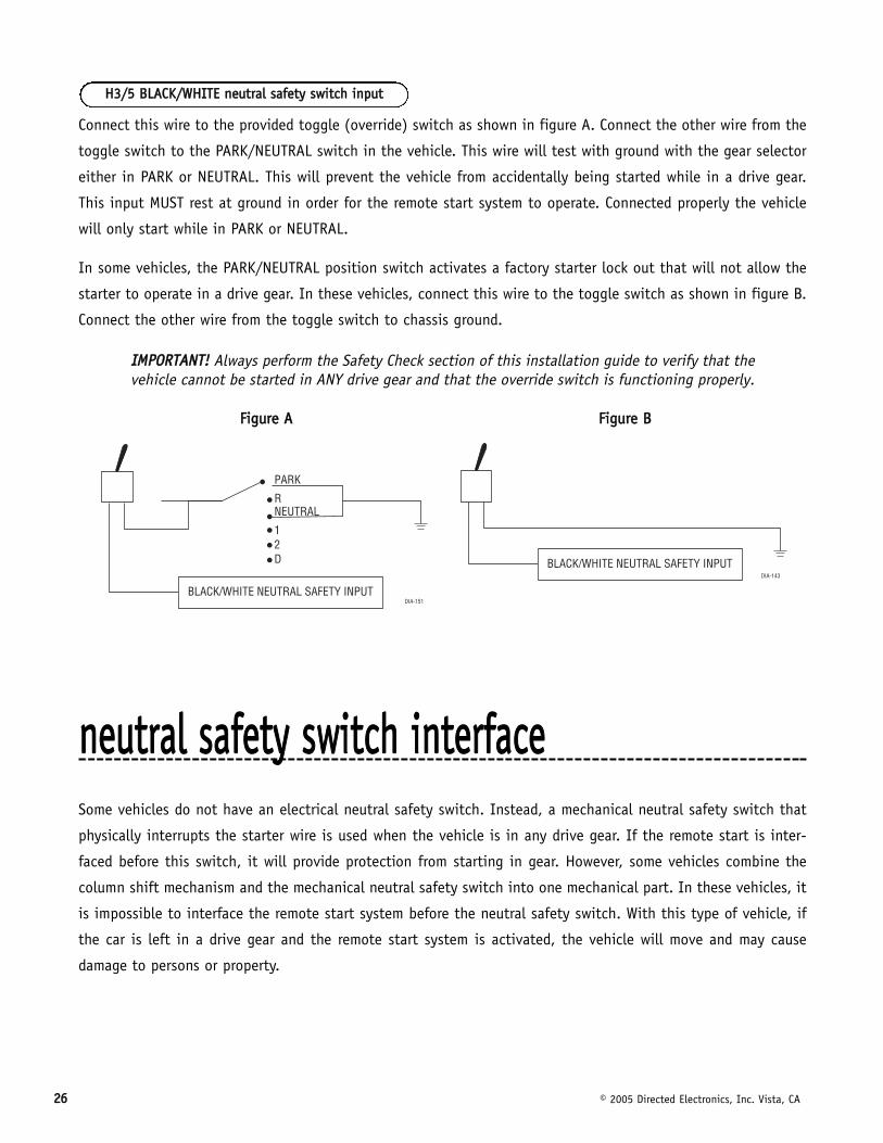
Connect this wire to the provided toggle (override) switch as shown in figure A. Connect the other wire from the
toggle switch to the PARK/NEUTRAL switch in the vehicle. This wire will test with ground with the gear selector
either in PARK or NEUTRAL. This will prevent the vehicle from accidentally being started while in a drive gear.
This input MUST rest at ground in order for the remote start system to operate. Connected properly the vehicle
will only start while in PARK or NEUTRAL.
In some vehicles, the PARK/NEUTRAL position switch activates a factory starter lock out that will not allow the
starter to operate in a drive gear. In these vehicles, connect this wire to the toggle switch as shown in figure B.
Connect the other wire from the toggle switch to chassis ground.
IIMMPPOORRTTAANNTT!! Always perform the Safety Check section of this installation guide to verify that thevehicle cannot be started in ANY drive gear and that the override switch is functioning properly.
FFiigguurree AA FFiigguurree BB
nneeuuttrraall ssaaffeettyy sswwiittcchh iinntteerrffaacceeSome vehicles do not have an electrical neutral safety switch. Instead, a mechanical neutral safety switch that
physically interrupts the starter wire is used when the vehicle is in any drive gear. If the remote start is inter-
faced before this switch, it will provide protection from starting in gear. However, some vehicles combine the
column shift mechanism and the mechanical neutral safety switch into one mechanical part. In these vehicles, it
is impossible to interface the remote start system before the neutral safety switch. With this type of vehicle, if
the car is left in a drive gear and the remote start system is activated, the vehicle will move and may cause
damage to persons or property.
HH33//55 BBLLAACCKK//WWHHIITTEE nneeuuttrraall ssaaffeettyy sswwiittcchh iinnppuutt

© 2005 Directed Electronics, Inc. Vista, CA 2277
According to available information, the only vehicles currently manufactured this way are most General Motors
trucks, sport utility vehicles and column shifting passenger cars. Available information also indicates that pre-
1996 Dodge Dakota pickups with 2.5 liter motors are manufactured this way as well.
GM vehicles that have the neutral safety switch built into the column shifter can usually be identified by a purple
starter wire. Typically, vehicles that use an outboard mechanical switch use a yellow wire from the ignition switch
to the mechanical switch and a purple wire from the mechanical switch to the starter itself. Remember, this is
only a rule of thumb and is not intended as a substitute for proper testing.
We suggest the following procedure to test for vehicles manufactured in this way.
NNOOTTEE:: You must complete the remote start system installation before doing the following test.Ensure that the remote start system is functioning normally. This includes connecting to thebrake as a shut-down.
1. Make sure there is adequate clearance to the front and rear of the vehicle because it may move slightly.
2. Make sure the hood is closed and there are no remote start shut-downs active.
3. Set the emergency brake.
4. Turn the key to the "run" position, this will release the shifter.
5. Place the car in drive (D).
6. Place your foot directly over the brake pedal, but do not depress it. Be ready to step on the brake if the
starter engages.
7. Activate the remote start system.
8. If the starter engages, immediately depress the brake to shut the remote start system down. If the starter
does not engage, no additional safety system is required.
If the starter engages and the vehicle is a General Motors product or Dodge Dakota pickup, refer to the follow-
ing text and diagrams for an alternative shut-down method which will prevent the starter from engaging. If the
vehicle is not a General Motors product or a Dodge Dakota pickup, please call Directed Electronics Technical
Support for an alternative shut-down method. Do not return the vehicle to the customer until this feature is
properly installed!
Every vehicle built in this fashion requires that the shifter be placed in park to remove the keys from the igni-
tion. As a result, it is possible to use the key-in-ignition sense switch to prevent remote starting if the keys are
in the ignition. The following diagrams illustrate how to accomplish this. The first diagram applies to all General
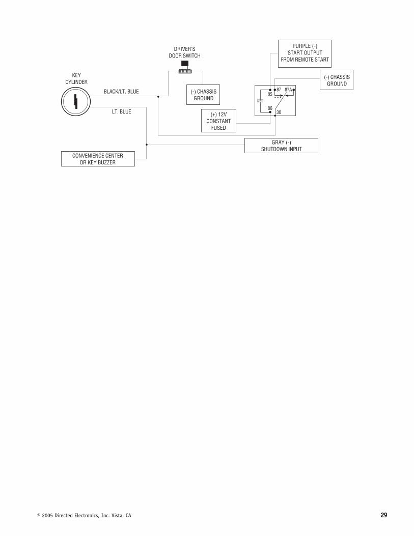
Motors vehicles at the present time. The second diagram applies to all pre-1996 Dodge Dakota pickup trucks with
2.5 liter motors. This solution has one side effect - if the customer inserts the key in the ignition with the driver's
door open, the remote start system will shut down. If this interface is used it is important to inform the cus-
tomer to close the driver’s door before inserting the key into the ignition when the remote start is active. This
tteessttiinngg tthhee nneeuuttrraall ssaaffeettyy sswwiittcchh
2288 © 2005 Directed Electronics, Inc. Vista, CA
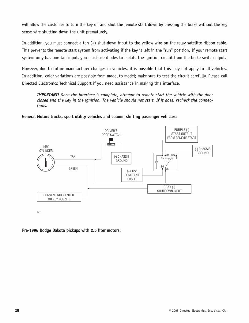
will allow the customer to turn the key on and shut the remote start down by pressing the brake without the key
sense wire shutting down the unit prematurely.
In addition, you must connect a tan (+) shut-down input to the yellow wire on the relay satellite ribbon cable.
This prevents the remote start system from activating if the key is left in the "run" position. If your remote start
system only has one tan input, you must use diodes to isolate the ignition circuit from the brake switch input.
However, due to future manufacturer changes in vehicles, it is possible that this may not apply to all vehicles.
In addition, color variations are possible from model to model; make sure to test the circuit carefully. Please call
Directed Electronics Technical Support if you need assistance in making this interface.
IIMMPPOORRTTAANNTT!! Once the interface is complete, attempt to remote start the vehicle with the doorclosed and the key in the ignition. The vehicle should not start. If it does, recheck the connec-tions.
GGeenneerraall MMoottoorrss ttrruucckkss,, ssppoorrtt uuttiilliittyy vveehhiicclleess aanndd ccoolluummnn sshhiiffttiinngg ppaasssseennggeerr vveehhiicclleess::
PPrree--11999966 DDooddggee DDaakkoottaa ppiicckkuuppss wwiitthh 22..55 lliitteerr mmoottoorrss::
© 2005 Directed Electronics, Inc. Vista, CA 2299
3300 © 2005 Directed Electronics, Inc. Vista, CA
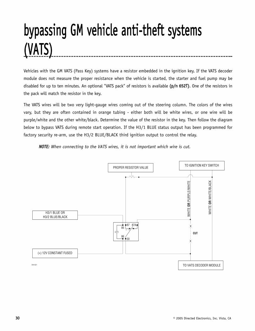
bbyyppaassssiinngg GGMM vveehhiiccllee aannttii--tthheefftt ssyysstteemmss((VVAATTSS))Vehicles with the GM VATS (Pass Key) systems have a resistor embedded in the ignition key. If the VATS decoder
module does not measure the proper resistance when the vehicle is started, the starter and fuel pump may be
disabled for up to ten minutes. An optional "VATS pack" of resistors is available ((pp//nn 665522TT)). One of the resistors in
the pack will match the resistor in the key.
The VATS wires will be two very light-gauge wires coming out of the steering column. The colors of the wires
vary, but they are often contained in orange tubing - either both will be white wires, or one wire will be
purple/white and the other white/black. Determine the value of the resistor in the key. Then follow the diagram
below to bypass VATS during remote start operation. If the H3/1 BLUE status output has been programmed for
factory security re-arm, use the H3/2 BLUE/BLACK third ignition output to control the relay.
NNOOTTEE:: When connecting to the VATS wires, it is not important which wire is cut.
��������������������� ��
������������ �������
��
����
�� ��
�� ����
��� �������!��"����
#
#
���
$�$���������� ��
��� ��������%���
"�������"������ ��
"�������$��$��"���
© 2005 Directed Electronics, Inc. Vista, CA 3311
11999955 aanndd nneewweerr vveehhiiccllee aannttii--tthheefftt ssyysstteemmss((iimmmmoobbiilliizzeerrss)) 1995 and newer vehicle anti-theft systems (immobilizers) require a bypass module. The bypass module allows for
easy interfacing, while still maintaining the OEM system’s integrity.
The Passlock I and Passlock II systems can be found in the following General Motors vehicles:
■ ‘95 and newer Cavalier and Sunfire
■ ‘96 and newer Achieva, Grand Am, and Skylark
■ ‘97 and newer Intrigue, Malibu, and Cutlass
■ ‘98 and newer trucks, vans, SUVs
■ ‘99 and newer Alero
■ 2000 and newer Impala and Saturn
Passlock I and II systems are VATS-evolved. Passlock systems still rely on the R-code to start, but the pellet is
no longer placed in the key. The resistor can now be found in the key switch. This allows for a greater number
of possible R-codes. In addition, Passlock systems require “seeing” the correct R-code at the correct time. To
bypass Passlock I and II, pp//nn 555555LL or pp//nn 555555TT is required.
The Passkey III system can be found in the following vehicles:
■ ‘97 and newer Park Avenue
■ ‘98 and newer Cadillac
■ ‘99 and newer U vans, Transport, Montana, and Silhouette
■ 2000 and newer Grand Prix, Lesabre, Monte Carlo, Lumina, Bonneville
■ 2001 and newer Aurora, Aztek and Rendezvous
Other transponder-based systems include: Acura, BMW, Dodge/Chrysler/Jeep, Ford, Honda, Infinity, Mazda,
Mercedes, Mitsubishi, Nissan, Toyota, Volkswagon, and Volvo.
PK-3 and the transponder-based systems use a transponder system that locks out the ignition and fuel system.
This transponder system is comprised of two parts. The first part, the transceiver, circles the key switch and is
activated when the key is placed in the key switch or turned to the run position. Upon activation, the trans-
ppaasssskkeeyy IIIIII ((PPKK--33)),, ttrraannssppoonnddeerr--bbaasseedd ssyysstteemmss
ppaasssslloocckk II aanndd ppaasssslloocckk IIII ((PPLL--11 aanndd PPLL--22))
3322 © 2005 Directed Electronics, Inc. Vista, CA
ceiver will excite the transponder, which is located (but not visible) in the head of the ignition key. The key
transponder will then send a unique code back to the transceiver for evaluation. If the code matches a valid code
of the system, the vehicle will be allowed to start. Most of these transponder-based systems can be bypassed
using pp//nn 555555UU.. Some may require additional parts from the vehicle manufacturer. Consult you dealer for the
applications. For most Ford PATS transponders, pp//nn 555555FF can be used, except for the following vehicles, which
will require pp//nn 555555UU: ‘97 and newer Mark VII, and 2000 and newer Taurus/Sable, Contour/Mystique and Focus.
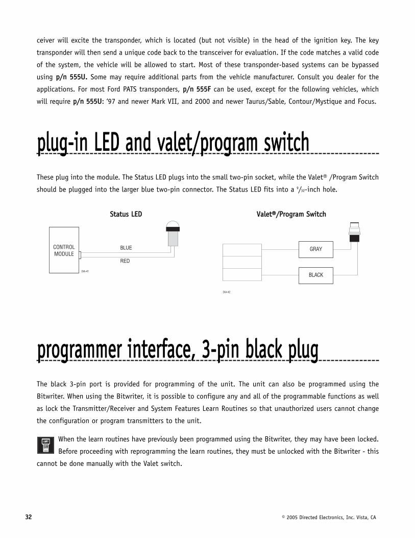
pplluugg--iinn LLEEDD aanndd vvaalleett//pprrooggrraamm sswwiittcchhThese plug into the module. The Status LED plugs into the small two-pin socket, while the Valet® /Program Switch
should be plugged into the larger blue two-pin connector. The Status LED fits into a 9/32-inch hole.
SSttaattuuss LLEEDD VVaalleett®®//PPrrooggrraamm SSwwiittcchh
pprrooggrraammmmeerr iinntteerrffaaccee,, 33--ppiinn bbllaacckk pplluuggThe black 3-pin port is provided for programming of the unit. The unit can also be programmed using the
Bitwriter. When using the Bitwriter, it is possible to configure any and all of the programmable functions as well
as lock the Transmitter/Receiver and System Features Learn Routines so that unauthorized users cannot change
the configuration or program transmitters to the unit.
When the learn routines have previously been programmed using the Bitwriter, they may have been locked.
Before proceeding with reprogramming the learn routines, they must be unlocked with the Bitwriter - this
cannot be done manually with the Valet switch.
�� �&�
© 2005 Directed Electronics, Inc. Vista, CA 3333
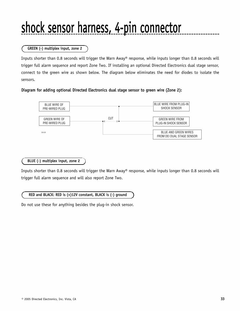
sshhoocckk sseennssoorr hhaarrnneessss,, 44--ppiinn ccoonnnneeccttoorr
Inputs shorter than 0.8 seconds will trigger the Warn Away® response, while inputs longer than 0.8 seconds will
trigger full alarm sequence and report Zone Two. If installing an optional Directed Electronics dual stage sensor,
connect to the green wire as shown below. The diagram below eliminates the need for diodes to isolate the
sensors.
DDiiaaggrraamm ffoorr aaddddiinngg ooppttiioonnaall DDiirreecctteedd EElleeccttrroonniiccss dduuaall ssttaaggee sseennssoorr ttoo ggrreeeenn wwiirree ((ZZoonnee 22))::
Inputs shorter than 0.8 seconds will trigger the Warn Away® response, while inputs longer than 0.8 seconds will
trigger full alarm sequence and will also report Zone Two.
Do not use these for anything besides the plug-in shock sensor.
RREEDD aanndd BBLLAACCKK:: RREEDD iiss ((++))1122VV ccoonnssttaanntt,, BBLLAACCKK iiss ((--)) ggrroouunndd
BBLLUUEE ((--)) mmuullttiipplleexx iinnppuutt,, zzoonnee 22
GGRREEEENN ((--)) mmuullttiipplleexx iinnppuutt,, zzoonnee 22
3344 © 2005 Directed Electronics, Inc. Vista, CA
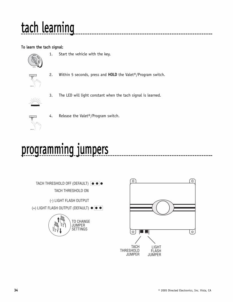
ttaacchh lleeaarrnniinnggTToo lleeaarrnn tthhee ttaacchh ssiiggnnaall::
1. Start the vehicle with the key.
2. Within 5 seconds, press and HHOOLLDD the Valet®/Program switch.
3. The LED will light constant when the tach signal is learned.
4. Release the Valet®/Program switch.
pprrooggrraammmmiinngg jjuummppeerrss
DRW-96
© 2005 Directed Electronics, Inc. Vista, CA 3355
In most cases, this jumper can be left in the OFF position. Some new vehicles use less than 12 volts in their
ignition systems. The unit may have trouble learning the tach signal in these vehicles. Changing the jumper to
the ON setting changes the trigger threshold of the digital tach circuit so it will work properly with these vehi-
cles. These vehicles include many newer Dodge/Chrysler/Plymouths, such as the Neon Cirrus/Stratus/Breeze and
LH-based cars.
This jumper is used to determine the light flash output. In the (+) position, the on-board relay is enabled and
the unit will output (+)12V on the WHITE wire, H1/2. In the (-) position, the on-board relay is disabled. The
WHITE wire, H1/2, will supply a 200 mA (-) output suitable for driving factory parking light relays. K
NNOOTTEE:: For parking light circuits that draw 10 amps or more, the internal jumper must be switchedto a (-) light flash output. PP//NN 88661177 or a standard automotive SPDT relay must be used on theH1/2 light flash output harness wire.
ttrraannssmmiitttteerr//rreecceeiivveerr lleeaarrnn rroouuttiinnee™™
The system comes with transmitters that have been taught to the receiver. The receiver can store up to 4 dif-
ferent transmitter codes in memory. Use the following learn routine to add transmitters to the system or to
change button assignments if desired.
The learn routine may be locked if previously programmed using the Bitwriter. If the horn generates one long
honk when attempting to program the unit, the learn routine is locked and must be unlocked using the Bitwriter™
before proceeding.
The Valet/Program switch, plugged into the blue port, is used for programming. There is a basic sequence of steps
to remember whenever programming this unit: Door, Key, Choose, Transmit and Release.
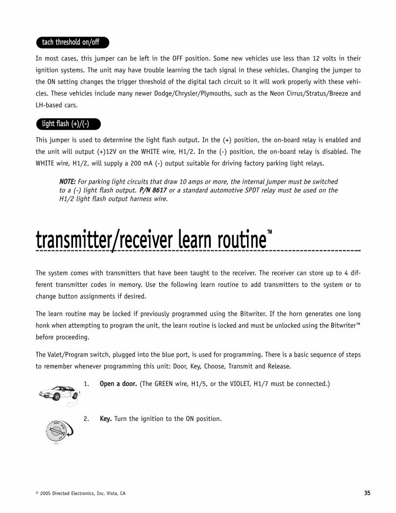
1. OOppeenn aa ddoooorr.. (The GREEN wire, H1/5, or the VIOLET, H1/7 must be connected.)
2. KKeeyy.. Turn the ignition to the ON position.
lliigghhtt ffllaasshh ((++))//((--))
ttaacchh tthhrreesshhoolldd oonn//ooffff
3366 © 2005 Directed Electronics, Inc. Vista, CA
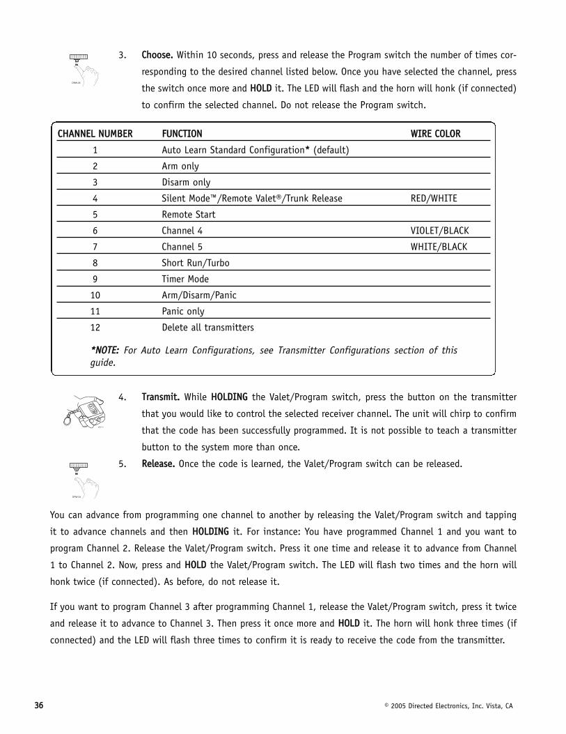
3. CChhoooossee.. Within 10 seconds, press and release the Program switch the number of times cor-
responding to the desired channel listed below. Once you have selected the channel, press
the switch once more and HHOOLLDD it. The LED will flash and the horn will honk (if connected)
to confirm the selected channel. Do not release the Program switch.
4. TTrraannssmmiitt.. While HHOOLLDDIINNGG the Valet/Program switch, press the button on the transmitter
that you would like to control the selected receiver channel. The unit will chirp to confirm
that the code has been successfully programmed. It is not possible to teach a transmitter
button to the system more than once.
5. RReelleeaassee.. Once the code is learned, the Valet/Program switch can be released.
You can advance from programming one channel to another by releasing the Valet/Program switch and tapping
it to advance channels and then HHOOLLDDIINNGG it. For instance: You have programmed Channel 1 and you want to
program Channel 2. Release the Valet/Program switch. Press it one time and release it to advance from Channel
1 to Channel 2. Now, press and HHOOLLDD the Valet/Program switch. The LED will flash two times and the horn will
honk twice (if connected). As before, do not release it.
If you want to program Channel 3 after programming Channel 1, release the Valet/Program switch, press it twice
and release it to advance to Channel 3. Then press it once more and HHOOLLDD it. The horn will honk three times (if
connected) and the LED will flash three times to confirm it is ready to receive the code from the transmitter.
CCHHAANNNNEELL NNUUMMBBEERR FFUUNNCCTTIIOONN WWIIRREE CCOOLLOORR
1 Auto Learn Standard Configuration** (default)
2 Arm only
3 Disarm only
4 Silent Mode™/Remote Valet®/Trunk Release RED/WHITE
5 Remote Start
6 Channel 4 VIOLET/BLACK
7 Channel 5 WHITE/BLACK
8 Short Run/Turbo
9 Timer Mode
10 Arm/Disarm/Panic
11 Panic only
12 Delete all transmitters
**NNOOTTEE:: For Auto Learn Configurations, see Transmitter Configurations section of thisguide.
© 2005 Directed Electronics, Inc. Vista, CA 3377
LLeeaarrnn RRoouuttiinnee wwiillll bbee eexxiitteedd iiff::
■ Door is closed.
■ Ignition is turned off.
■ Program switch is pressed too many times.
■ More than 15 seconds between steps.
ttrraannssmmiitttteerr ccoonnffiigguurraattiioonnssThe transmitters can be programmed with the standard or single button arm/disarm configurations by using the
Auto Learn functions in the Transmitter/Receiver Learn Routine.
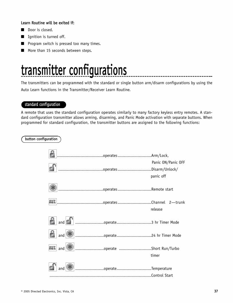
A remote that uses the standard configuration operates similarly to many factory keyless entry remotes. A stan-dard configuration transmitter allows arming, disarming, and Panic Mode activation with separate buttons. Whenprogrammed for standard configuration, the transmitter buttons are assigned to the following functions:
.....................................operates ...........................Arm/Lock,
Panic ON/Panic OFF
....................................operates ...........................Disarm/Unlock/
panic off
....................................operates ...........................Remote start
.....................................operates ...........................Channel 2—trunk
release
and .......................operate............................3 hr Timer Mode
and .......................operate............................24 hr Timer Mode
and .......................operate ..........................Short Run/Turbo
timer
and .......................operate............................Temperature
..................................................................................Control Start
bbuuttttoonn ccoonnffiigguurraattiioonn
ssttaannddaarrdd ccoonnffiigguurraattiioonn
3388 © 2005 Directed Electronics, Inc. Vista, CA
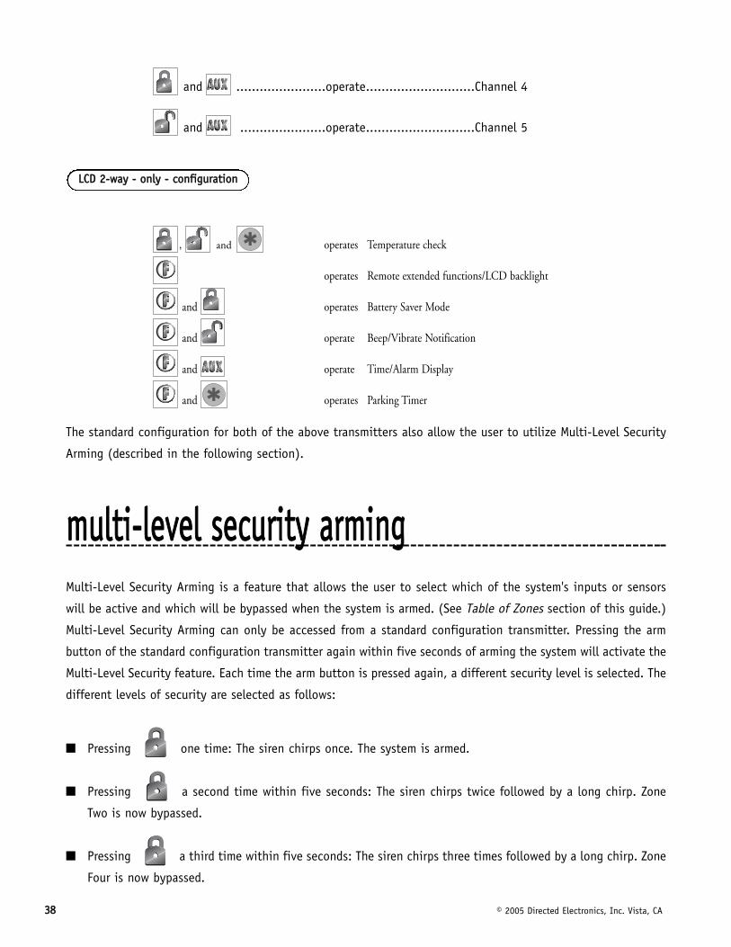
and .......................operate............................Channel 4
and ......................operate............................Channel 5
, and operates Temperature check
operates Remote extended functions/LCD backlight
and operates Battery Saver Mode
and operate Beep/Vibrate Notification
and operate Time/Alarm Display
and operates Parking Timer
The standard configuration for both of the above transmitters also allow the user to utilize Multi-Level Security
Arming (described in the following section).
mmuullttii--lleevveell sseeccuurriittyy aarrmmiinnggMulti-Level Security Arming is a feature that allows the user to select which of the system's inputs or sensors
will be active and which will be bypassed when the system is armed. (See Table of Zones section of this guide.)
Multi-Level Security Arming can only be accessed from a standard configuration transmitter. Pressing the arm
button of the standard configuration transmitter again within five seconds of arming the system will activate the
Multi-Level Security feature. Each time the arm button is pressed again, a different security level is selected. The
different levels of security are selected as follows:
■ Pressing one time: The siren chirps once. The system is armed.
■ Pressing a second time within five seconds: The siren chirps twice followed by a long chirp. Zone
Two is now bypassed.
■ Pressing a third time within five seconds: The siren chirps three times followed by a long chirp. Zone
Four is now bypassed.
LLCCDD 22--wwaayy -- oonnllyy -- ccoonnffiigguurraattiioonn
© 2005 Directed Electronics, Inc. Vista, CA 3399
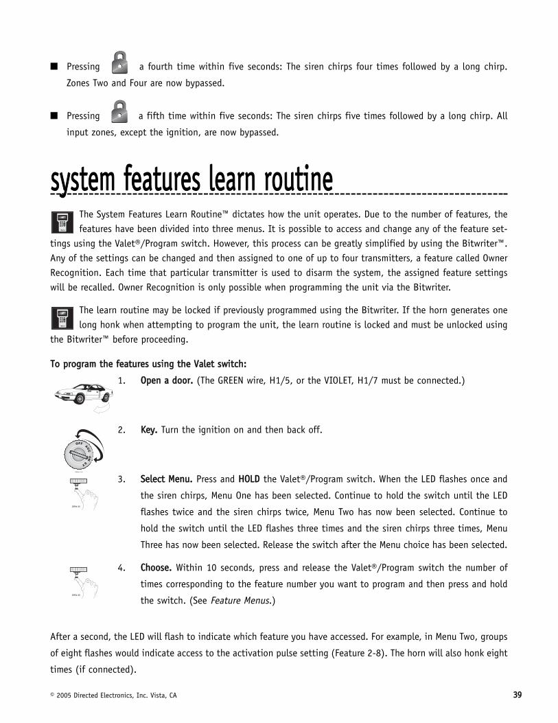
■ Pressing a fourth time within five seconds: The siren chirps four times followed by a long chirp.
Zones Two and Four are now bypassed.
■ Pressing a fifth time within five seconds: The siren chirps five times followed by a long chirp. All
input zones, except the ignition, are now bypassed.
ssyysstteemm ffeeaattuurreess lleeaarrnn rroouuttiinneeThe System Features Learn Routine™ dictates how the unit operates. Due to the number of features, thefeatures have been divided into three menus. It is possible to access and change any of the feature set-
tings using the Valet®/Program switch. However, this process can be greatly simplified by using the Bitwriter™.Any of the settings can be changed and then assigned to one of up to four transmitters, a feature called OwnerRecognition. Each time that particular transmitter is used to disarm the system, the assigned feature settingswill be recalled. Owner Recognition is only possible when programming the unit via the Bitwriter.
The learn routine may be locked if previously programmed using the Bitwriter. If the horn generates onelong honk when attempting to program the unit, the learn routine is locked and must be unlocked using
the Bitwriter™ before proceeding.
TToo pprrooggrraamm tthhee ffeeaattuurreess uussiinngg tthhee VVaalleett sswwiittcchh::
1. OOppeenn aa ddoooorr.. (The GREEN wire, H1/5, or the VIOLET, H1/7 must be connected.)
2. KKeeyy.. Turn the ignition on and then back off.
3. SSeelleecctt MMeennuu.. Press and HHOOLLDD the Valet®/Program switch. When the LED flashes once and
the siren chirps, Menu One has been selected. Continue to hold the switch until the LED
flashes twice and the siren chirps twice, Menu Two has now been selected. Continue to
hold the switch until the LED flashes three times and the siren chirps three times, Menu
Three has now been selected. Release the switch after the Menu choice has been selected.
4. CChhoooossee.. Within 10 seconds, press and release the Valet®/Program switch the number of
times corresponding to the feature number you want to program and then press and hold
the switch. (See Feature Menus.)
After a second, the LED will flash to indicate which feature you have accessed. For example, in Menu Two, groups
of eight flashes would indicate access to the activation pulse setting (Feature 2-8). The horn will also honk eight
times (if connected).
4400 © 2005 Directed Electronics, Inc. Vista, CA
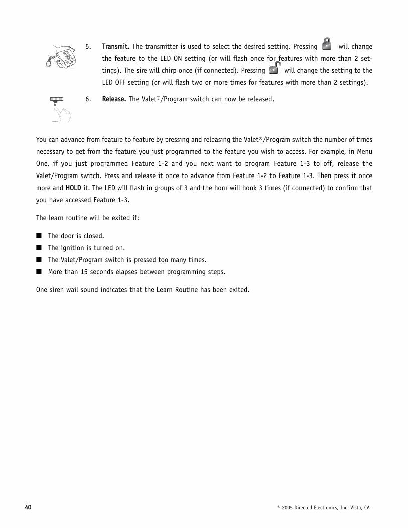
5. TTrraannssmmiitt.. The transmitter is used to select the desired setting. Pressing will change
the feature to the LED ON setting (or will flash once for features with more than 2 set-
tings). The sire will chirp once (if connected). Pressing will change the setting to the
LED OFF setting (or will flash two or more times for features with more than 2 settings).
6. RReelleeaassee.. The Valet®/Program switch can now be released.
You can advance from feature to feature by pressing and releasing the Valet®/Program switch the number of times
necessary to get from the feature you just programmed to the feature you wish to access. For example, in Menu
One, if you just programmed Feature 1-2 and you next want to program Feature 1-3 to off, release the
Valet/Program switch. Press and release it once to advance from Feature 1-2 to Feature 1-3. Then press it once
more and HHOOLLDD it. The LED will flash in groups of 3 and the horn will honk 3 times (if connected) to confirm that
you have accessed Feature 1-3.
The learn routine will be exited if:
■ The door is closed.
■ The ignition is turned on.
■ The Valet/Program switch is pressed too many times.
■ More than 15 seconds elapses between programming steps.
One siren wail sound indicates that the Learn Routine has been exited.
© 2005 Directed Electronics, Inc. Vista, CA 4411
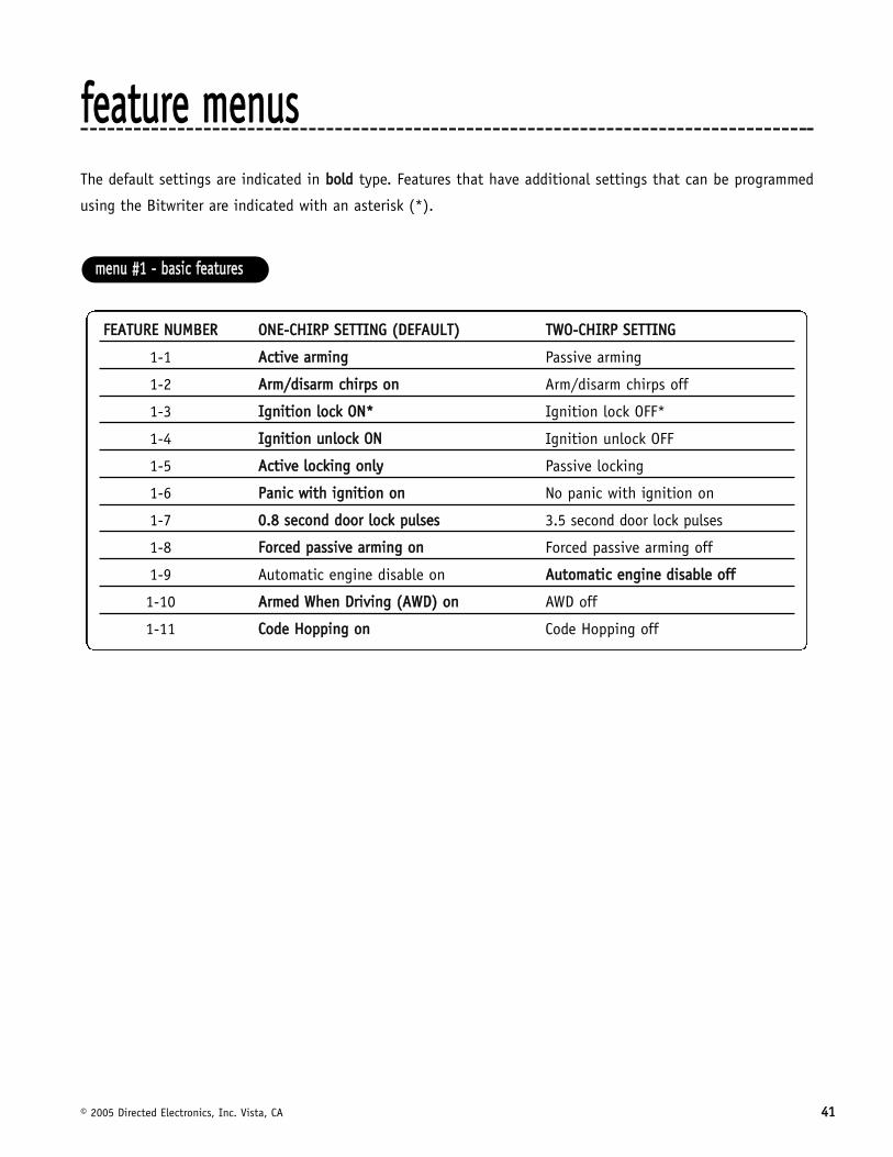
ffeeaattuurree mmeennuussThe default settings are indicated in bboolldd type. Features that have additional settings that can be programmed
using the Bitwriter are indicated with an asterisk (*).
FFEEAATTUURREE NNUUMMBBEERR OONNEE--CCHHIIRRPP SSEETTTTIINNGG ((DDEEFFAAUULLTT)) TTWWOO--CCHHIIRRPP SSEETTTTIINNGG
1-1 AAccttiivvee aarrmmiinngg Passive arming
1-2 AArrmm//ddiissaarrmm cchhiirrppss oonn Arm/disarm chirps off
1-3 IIggnniittiioonn lloocckk OONN** Ignition lock OFF*
1-4 IIggnniittiioonn uunnlloocckk OONN Ignition unlock OFF
1-5 AAccttiivvee lloocckkiinngg oonnllyy Passive locking
1-6 PPaanniicc wwiitthh iiggnniittiioonn oonn No panic with ignition on
1-7 00..88 sseeccoonndd ddoooorr lloocckk ppuullsseess 3.5 second door lock pulses
1-8 FFoorrcceedd ppaassssiivvee aarrmmiinngg oonn Forced passive arming off
1-9 Automatic engine disable on AAuuttoommaattiicc eennggiinnee ddiissaabbllee ooffff
1-10 AArrmmeedd WWhheenn DDrriivviinngg ((AAWWDD)) oonn AWD off
1-11 CCooddee HHooppppiinngg oonn Code Hopping off
mmeennuu ##11 -- bbaassiicc ffeeaattuurreess
4422 © 2005 Directed Electronics, Inc. Vista, CA
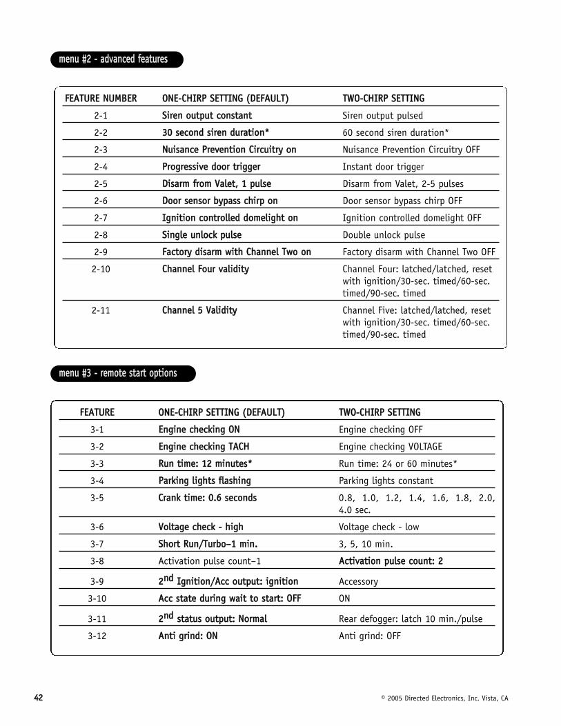
FFEEAATTUURREE OONNEE--CCHHIIRRPP SSEETTTTIINNGG ((DDEEFFAAUULLTT)) TTWWOO--CCHHIIRRPP SSEETTTTIINNGG
3-1 EEnnggiinnee cchheecckkiinngg OONN Engine checking OFF
3-2 EEnnggiinnee cchheecckkiinngg TTAACCHH Engine checking VOLTAGE
3-3 RRuunn ttiimmee:: 1122 mmiinnuutteess** Run time: 24 or 60 minutes*
3-4 PPaarrkkiinngg lliigghhttss ffllaasshhiinngg Parking lights constant
3-5 CCrraannkk ttiimmee:: 00..66 sseeccoonnddss 0.8, 1.0, 1.2, 1.4, 1.6, 1.8, 2.0, 4.0 sec.
3-6 VVoollttaaggee cchheecckk -- hhiigghh Voltage check - low
3-7 SShhoorrtt RRuunn//TTuurrbboo––11 mmiinn.. 3, 5, 10 min.
3-8 Activation pulse count–1 AAccttiivvaattiioonn ppuullssee ccoouunntt:: 22
3-9 22nndd IIggnniittiioonn//AAcccc oouuttppuutt:: iiggnniittiioonn Accessory
3-10 AAcccc ssttaattee dduurriinngg wwaaiitt ttoo ssttaarrtt:: OOFFFF ON
3-11 22nndd ssttaattuuss oouuttppuutt:: NNoorrmmaall Rear defogger: latch 10 min./pulse
3-12 AAnnttii ggrriinndd:: OONN Anti grind: OFF
mmeennuu ##33 -- rreemmoottee ssttaarrtt ooppttiioonnss
FFEEAATTUURREE NNUUMMBBEERR OONNEE--CCHHIIRRPP SSEETTTTIINNGG ((DDEEFFAAUULLTT)) TTWWOO--CCHHIIRRPP SSEETTTTIINNGG
2-1 SSiirreenn oouuttppuutt ccoonnssttaanntt Siren output pulsed
2-2 3300 sseeccoonndd ssiirreenn dduurraattiioonn** 60 second siren duration*
2-3 NNuuiissaannccee PPrreevveennttiioonn CCiirrccuuiittrryy oonn Nuisance Prevention Circuitry OFF
2-4 PPrrooggrreessssiivvee ddoooorr ttrriiggggeerr Instant door trigger
2-5 DDiissaarrmm ffrroomm VVaalleett,, 11 ppuullssee Disarm from Valet, 2-5 pulses
2-6 DDoooorr sseennssoorr bbyyppaassss cchhiirrpp oonn Door sensor bypass chirp OFF
2-7 IIggnniittiioonn ccoonnttrroolllleedd ddoommeelliigghhtt oonn Ignition controlled domelight OFF
2-8 SSiinnggllee uunnlloocckk ppuullssee Double unlock pulse
2-9 FFaaccttoorryy ddiissaarrmm wwiitthh CChhaannnneell TTwwoo oonn Factory disarm with Channel Two OFF
2-10 CChhaannnneell FFoouurr vvaalliiddiittyy Channel Four: latched/latched, reset with ignition/30-sec. timed/60-sec. timed/90-sec. timed
2-11 CChhaannnneell 55 VVaalliiddiittyy Channel Five: latched/latched, reset with ignition/30-sec. timed/60-sec. timed/90-sec. timed
mmeennuu ##22 -- aaddvvaanncceedd ffeeaattuurreess
© 2005 Directed Electronics, Inc. Vista, CA 4433
ffeeaattuurree ddeessccrriippttiioonnssThe features of the system are described below. Features that have additional settings that can be selected only
when programming with the Bitwriter are indicated by the following icon:
11--11 AACCTTIIVVEE//PPAASSSSIIVVEE AARRMMIINNGG:: When active arming is selected, the system will only arm when the transmitter is
used. When set to passive, the system will arm automatically 30 seconds after the last door is closed. To alert
the consumer of passive arming, the siren will chirp 20 seconds after the door is closed. This provides the con-
sumer with an audible warning prior to the system actually arming. At the 30 second mark, the system will arm,
but the siren will not chirp.
11--22 CCHHIIRRPPSS OONN//OOFFFF:: This feature controls the chirps that confirm the arming and disarming of the system.
11--33 IIGGNNIITTIIOONN CCOONNTTRROOLLLLEEDD DDOOOORR LLOOCCKKSS OONN//OOFFFF:: When turned on, the doors will lock three seconds after the igni-
tion is turned on and unlock when the ignition is turned off. There are separate steps for ignition lock and
ignition unlock. They can be programmed on or off independently.
11--44 IIGGNNIITTIIOONN CCOONNTTRROOLLLLEEDD UUNNLLOOCCKK:: When turned ON the doors will unlock when the ignition is turned OFF.
11--55 AACCTTIIVVEE//PPAASSSSIIVVEE LLOOCCKKIINNGG:: If passive arming is selected in Feature 1-1, then the system can be programmed
to either lock the doors when passive arming occurs, or only lock the doors when the system is armed via the
transmitter. Active locking means the system will not lock the doors when it passively arms. Passive locking
means that the system will lock the doors when it passively arms.
NNOOTTEE:: Remember, when passive arming is selected, the unit will chirp 20 seconds after the lastdoor is closed. The system does not actually arm or lock the doors until 30 seconds after thedoor has been closed.
11--66 PPAANNIICC WWIITTHH IIGGNNIITTIIOONN OONN:: This feature controls whether or not the panic mode is available with the igni-
tion on. In some states, there are laws prohibiting a siren sounding in a moving vehicle. This feature makes the
system compliant with these regulations.
mmeennuu ##11 -- bbaassiicc ffeeaattuurreess
4444 © 2005 Directed Electronics, Inc. Vista, CA
11--77 DDOOOORR LLOOCCKK PPUULLSSEE DDUURRAATTIIOONN:: Some European vehicles, such as Mercedes-Benz and Audi, require longer lock
and unlock pulses to operate the vacuum pump. Programming the system to provide 3.5 second pulses, will
accommodate the door lock interface in these vehicles. The default setting is 0.8 second door lock pulses. Some
modification to the door lock harness (H2) is also necessary. (See (+/-) Door Lock Outputs Harness (H4) section,
"Type E - Mercedes-Benz and Audi -1985 and Newer" diagram.)
11--88 FFOORRCCEEDD PPAASSSSIIVVEE AARRMMIINNGG OONN//OOFFFF:: To use this feature, passive arming must be selected in Feature 1-1. When
turned on, forced passive arming will ensure that the system will passively arm, even if a zone is left open or
invalid. Forced passive arming occurs one hour after the ignition is turned off.
11--99 AAUUTTOOMMAATTIICC EENNGGIINNEE DDIISSAABBLLEE ((AAEEDD)) OONN//OOFFFF: AED is a full-time, passive starter disable that works independ-
ently of the security system. When turned on, the orange, ground-when-armed output (H1/1) will activate 30
seconds after the ignition is turned off. The LED will flash at half its normal rate when the ignition is turned off
to indicate that AED is active and will interrupt the starter in 30 seconds. AED does not occur in Valet® mode
and can be bypassed using the emergency override procedure. The transmitter can be used to disarm AED,
however, the system must be armed and then disarmed, using the transmitter, to disarm AED.
11--1100 AARRMMEEDD WWHHIILLEE DDRRIIVVIINNGG ((AAWWDD)) OONN//OOFFFF:: In the default setting (Armed While Driving), the system can be
armed with the ignition on. When armed, the ground-when-armed is not active and the sensors are bypassed. The
door triggers will remain active.
11--1111 CCOODDEE HHOOPPPPIINNGG™™ OONN//OOFFFF:: The system uses a mathematical formula to change its code each time the trans-
mitter and receiver communicate. This makes the group of bits or "word" from the transmitter very long. The
longer the word is, the easier it is to block its transmission to the unit. Disabling the Code Hopping™ feature lets
the receiver ignore the Code Hopping™ part of the transmitted word. As a result, the unit may have better range
with Code Hopping™ off.
22--11 SSIIRREENN OOUUTTPPUUTT CCOONNSSTTAANNTT//PPUULLSSEEDD:: The system can be programmed to output pulses instead of a continuous
output when the system is triggered. This is useful to honk the factory horn in applications where a siren is unde-
sirable. Remember that the unit is only capable of supplying 1 amp of current. A relay will be required to interface
with most factory horn systems.
22--22 SSIIRREENN DDUURRAATTIIOONN 3300//6600 SSEECCOONNDDSS:: It is possible to program the unit to sound for 30 or 60 seconds
during the triggered sequence. Some states have laws regulating how long a security system can sound.
When using the Bitwriter™, the siren can be programmed to sound for any length of time from 1 second to 180
seconds. Use the right and left arrows or the plus (+) and minus (-) keys on the keyboard to change the siren
duration in 1 second intervals. Holding down the key will rapidly increase or decrease the setting.
mmeennuu ##22 -- aaddvvaanncceedd ffeeaattuurreess
© 2005 Directed Electronics, Inc. Vista, CA 4455
22--33 NNUUIISSAANNCCEE PPRREEVVEENNTTIIOONN CCIIRRCCUUIITTRRYY™™ ((NNPPCC™™)) OONN//OOFFFF:: NPC™ stops repeated triggering of the same zone. If
one zone is triggered three times in one hour, that zone is bypassed for one hour, starting from the time of the
third trigger. During that hour, if the system sees a trigger on that zone again, the system resets the one hour
timer. If one hour passes and the zone has not triggered again, the zone is activated and can trigger the system
again. NPC™ only monitors sensor inputs, and does not bypass the door trigger or the ignition trigger at any
time. If NPC™ is turned off, the system will respond to repeated triggers on the sensor inputs and will do so
indefinitely. Some states have laws regulating how many times a security system can trigger before it is consid-
ered a nuisance and the vehicle is towed away.
22--44 PPRROOGGRREESSSSIIVVEE DDOOOORR TTRRIIGGGGEERR OONN//OOFFFF:: The system responds to a door trigger input with a progressive
response. When the door is opened with the system armed, the siren will chirp 10 times prior to the full trig-
gered sequence. The door trigger is still treated as an instant trigger and closing the door quickly will not prevent
full triggered sequence from occurring. If the progressive door trigger is programmed off, the full siren output
will occur the moment the door is opened.
22--55 VVAALLEETT PPUULLSSEE CCOOUUNNTT 11 TTOO 55 PPUULLSSEESS:: The system can be programmed to count the number of presses of the
valet switch before disarming the security system. The factory default setting is one pulse. The unit can also be
set for two to five pulses.
Ghost Switch option: For added security, the GRAY wire on the two-pin Valet®/Program plug can be connected to
any switch in the vehicle that provides a positive (+) momentary pulse.
22--66 DDOOOORR SSEENNSSOORR BBYYPPAASSSS CCHHIIRRPP OONN//OOFFFF:: This feature controls the error chirp that is generated if the system is
armed with the door trigger active. This is useful in vehicles that have a long dome light delay after the door
has been closed. If the system is armed before the dome light has turned off, the security system will generate
the door trigger error chirp. If this error chirp is not desired, use this feature to disable the door open error chirp.
If the bypass chirp is turned off, no bypass chirp will be generated, even if a door is accidentally left open.
22--77 IIGGNNIITTIIOONN CCOONNTTRROOLLLLEEDD DDOOMMEE LLIIGGHHTT SSUUPPEERRVVIISSIIOONN OONN//OOFFFF:: If turned on, the system will turn on the dome
light for 60 seconds when the ignition is turned off. The optional dome light supervision feature must be installed
as described in the Wire Connection Guide.
22--88 DDOOUUBBLLEE PPUULLSSEE UUNNLLOOCCKK OONN//OOFFFF:: Some vehicles require two pulses on a single wire to unlock the doors. When
the double pulse unlock feature is turned on, the BLUE wire will supply two negative pulses instead of a single
pulse. At the same time, the GREEN wire will supply two positive pulses instead of a single pulse. This makes it
possible to directly interface with double pulse vehicles without any extra parts.
22--99 FFAACCTTOORRYY AALLAARRMM DDIISSAARRMM WWIITTHH CCHHAANNNNEELL 22:: In the default setting the factory alarm disarm output will disarm
the factory alarm system any time the button(s) controlling Channel Two is pressed.
4466 © 2005 Directed Electronics, Inc. Vista, CA
22--1100 CCHHAANNNNEELL 44 VVAALLIIDDIITTYY//LLAATTCCHHEEDD//LLAATTCCHHEEDD RREESSEETT WWIITTHH IIGGNNIITTIIOONN//3300 SSEECCOONNDD TTIIMMEEDD//9900 SSEECCOONNDD TTIIMMEEDD
OOUUTTPPUUTT:: This wire provides a (-) 200mA output whenever the transmitter button(s) controlling Channel 4 is
pressed. This output can be programmed to provide the following types of outputs (see also the Feature Menus
section):
■ VVaalliiddiittyy:: Output that will send a signal as long as the transmission is received.
■ LLaattcchheedd:: Output that will send a signal when the Channel 4 button(s) is pressed and will continue until the
same button(s) is pressed again.
■ LLaattcchheedd,, rreesseett wwiitthh iiggnniittiioonn:: Similar to the latched output, this type of output turns on the first time the
Channel 4 button(s) is pressed and turns off the next time the same button is pressed. This type of output
additionally stops and resets whenever the ignition is turned on and then off.
■ 3300--sseeccoonndd ttiimmeedd:: Output that will send a continuous signal for 30 seconds.
■ 9900--sseeccoonndd ttiimmeedd:: Output that will send a continuous signal for 90 seconds.
22--1111 CCHHAANNNNEELL 55 VVAALLIIDDIITTYY//LLAATTCCHHEEDD//LLAATTCCHHEEDD RREESSEETT WWIITTHH IIGGNNIITTIIOONN//3300 SSEECCOONNDD TTIIMMEEDD//9900 SSEECCOONNDD TTIIMMEEDD
OOUUTTPPUUTT:: Channel Four can be programmed for these output configurations. The unit is set to the default valid-
ity output. To change the configuration, use the two-chirp setting to toggle through the different configurations.
Refer to channel 4 feature 2-10 for additional detail.
33--11 EENNGGIINNEE CCHHEECCKKIINNGG OONN//OOFFFF:: In the default setting the remote start will monitor either the vehicle's tach wire
or voltage depending on the programming of feature 3-2. If programmed OFF the vehicle will crank for the pro-
grammed crank time (feature 3-5) and will not verify with tach or voltage that the car is running. In the OFF
setting, if the vehicle fails to start, the ignition can stay on for the entire run duration. Using tach or voltage
check is always recommended if possible.
33--22 CCHHEECCKKIINNGG TTYYPPEE TTAACCHH//VVOOLLTTAAGGEE:: Selects the method of engine monitoring. If set to TACHOMETER the unit will
reference the learned tach signal to disengage the starter. In addition it will monitor the RPM and shut down if
the engine RPM is too high or too low. When set to VOLTAGE, the unit will crank the starter for the programmed
time and then attempt to sense that the engine is running by detecting an increase in voltage. The threshold
for the voltage check is selectable in feature 3-6.
33--33 RRUUNN TTIIMMEE 1122,, 2244,, 6600 MMIINNUUTTEESS:: Selects the time in minutes that the system will operate the engine
until the system "times out". This is the maximum operation period and the system may be shut down
using a shutdown at any time. Using the Bitwriter, the run time can be programmed for any duration from 1-60
minutes.
mmeennuu ##33 -- rreemmoottee ssttaarrtt ooppttiioonnss
© 2005 Directed Electronics, Inc. Vista, CA 4477
33--44 PPAARRKKIINNGG LLIIGGHHTTSS FFLLAASSHHIINNGG//CCOONNSSTTAANNTT:: In the default setting, the unit will flash the vehicle's parking lights
(if connected) while remote started. The constant setting will turn the parking lights on solid for the entire run
duration.
33--55 CCRRAANNKK TTIIMMEE 00..66//00..88//11..00//11..22//11..44//11..66//11..88//22..00//44..00 SSEECCOONNDDSS:: If the unit is programmed for no engine check-
ing or voltage sense, the crank time must be set to the appropriate duration. The default setting is 0.6 second.
If a different crank time is desired, select feature 3-5 and select either 0.6 second by using the one-chirp setting
or toggle through the higher settings by using the two-chirp settings.
33--66 VVOOLLTTAAGGEE CCHHEECCKK HHII//LLOOWW:: This feature only functions when programmed for voltage sense. Some vehicles have
many accessories, which are turned on when remote started. In these vehicles, the variation of voltage between
the engine off and the car running is very small and the remote start unit may "think" the vehicle has not started.
This can cause the remote start to shut-down after the car has been started. If this happens program this feature
to the LOW position.
33--77 SSHHOORRTT RRUUNN//TTUURRBBOO:: When the and buttons on the transmitter are pressed simultaneously, the
vehicle will start for the programmed short run time. The factory default is 1 minute.
33--88 AACCTTIIVVAATTIIOONN PPUULLSSEE CCOOUUNNTT:: This allows the system to use 1 or 2 pulses to activate the remote start sequence.
NNoottee!! 1 or 2 pulses on the WHITE/BLUE remote start activation input wire as well as thebutton of the remote control.
33--99 22nndd IIGGNNIITTIIOONN//22nndd AACCCCEESSSSOORRYY OOUUTTPPUUTT:: This will allow the PINK/WHITE to be used as a 2nd ignition or an
accessory.
33--1100 AACCCCEESSSSOORRYY SSTTAATTEE DDUURRIINNGG WWAAIITT--TTOO--SSTTAARRTT:: This feature will allow the selection of the accessory output to
be ON or OFF during wait-to-start.
33--1111 22nndd SSTTAATTUUSS OOUUTTPPUUTT:: This feature will allow selection of status output or a rear defogger mode that turns
on ten seconds after the vehicle has started. The defogger mode has two selections, latched or pulsed. Latched
mode will only stay on for 10 minutes.
33--1122 AANNTTII--GGRRIINNDD OONN//OOFFFF:: With the anti-grind On (default) the ground-when-armed output will be active during
remote start operation. If accessories such as a voice module or window module are added to the unit, it may be
necessary to program this feature off.
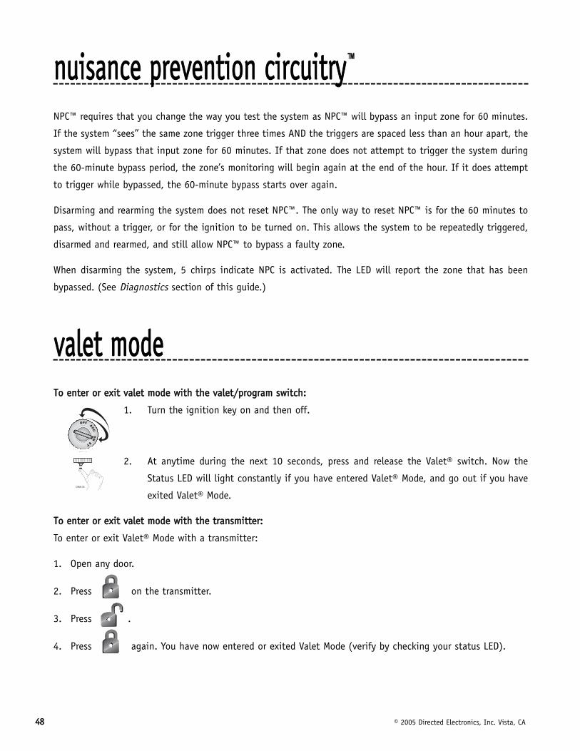
4488 © 2005 Directed Electronics, Inc. Vista, CA
nnuuiissaannccee pprreevveennttiioonn cciirrccuuiittrryy™™
NPC™ requires that you change the way you test the system as NPC™ will bypass an input zone for 60 minutes.
If the system “sees” the same zone trigger three times AND the triggers are spaced less than an hour apart, the
system will bypass that input zone for 60 minutes. If that zone does not attempt to trigger the system during
the 60-minute bypass period, the zone’s monitoring will begin again at the end of the hour. If it does attempt
to trigger while bypassed, the 60-minute bypass starts over again.
Disarming and rearming the system does not reset NPC™. The only way to reset NPC™ is for the 60 minutes to
pass, without a trigger, or for the ignition to be turned on. This allows the system to be repeatedly triggered,
disarmed and rearmed, and still allow NPC™ to bypass a faulty zone.
When disarming the system, 5 chirps indicate NPC is activated. The LED will report the zone that has been
bypassed. (See Diagnostics section of this guide.)
vvaalleett mmooddeeTToo eenntteerr oorr eexxiitt vvaalleett mmooddee wwiitthh tthhee vvaalleett//pprrooggrraamm sswwiittcchh::
1. Turn the ignition key on and then off.
2. At anytime during the next 10 seconds, press and release the Valet® switch. Now the
Status LED will light constantly if you have entered Valet® Mode, and go out if you have
exited Valet® Mode.
TToo eenntteerr oorr eexxiitt vvaalleett mmooddee wwiitthh tthhee ttrraannssmmiitttteerr::
To enter or exit Valet® Mode with a transmitter:
1. Open any door.
2. Press on the transmitter.
3. Press .
4. Press again. You have now entered or exited Valet Mode (verify by checking your status LED).
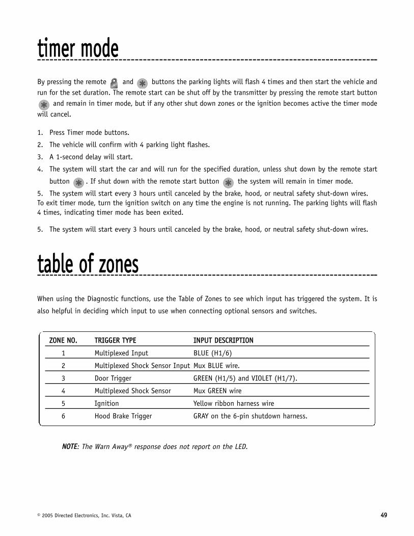
© 2005 Directed Electronics, Inc. Vista, CA 4499
ttiimmeerr mmooddeeBy pressing the remote and buttons the parking lights will flash 4 times and then start the vehicle andrun for the set duration. The remote start can be shut off by the transmitter by pressing the remote start button
and remain in timer mode, but if any other shut down zones or the ignition becomes active the timer modewill cancel.
1. Press Timer mode buttons.
2. The vehicle will confirm with 4 parking light flashes.
3. A 1-second delay will start.
4. The system will start the car and will run for the specified duration, unless shut down by the remote start
button . If shut down with the remote start button the system will remain in timer mode.
5. The system will start every 3 hours until canceled by the brake, hood, or neutral safety shut-down wires.To exit timer mode, turn the ignition switch on any time the engine is not running. The parking lights will flash4 times, indicating timer mode has been exited.
5. The system will start every 3 hours until canceled by the brake, hood, or neutral safety shut-down wires.
ttaabbllee ooff zzoonneessWhen using the Diagnostic functions, use the Table of Zones to see which input has triggered the system. It is
also helpful in deciding which input to use when connecting optional sensors and switches.
NNOOTTEE: The Warn Away® response does not report on the LED.
ZZOONNEE NNOO.. TTRRIIGGGGEERR TTYYPPEE IINNPPUUTT DDEESSCCRRIIPPTTIIOONN
1 Multiplexed Input BLUE (H1/6)
2 Multiplexed Shock Sensor Input Mux BLUE wire.
3 Door Trigger GREEN (H1/5) and VIOLET (H1/7).
4 Multiplexed Shock Sensor Mux GREEN wire
5 Ignition Yellow ribbon harness wire
6 Hood Brake Trigger GRAY on the 6-pin shutdown harness.
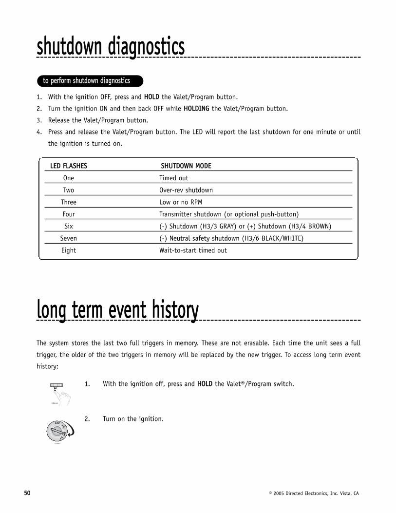
5500 © 2005 Directed Electronics, Inc. Vista, CA
sshhuuttddoowwnn ddiiaaggnnoossttiiccss
1. With the ignition OFF, press and HHOOLLDD the Valet/Program button.
2. Turn the ignition ON and then back OFF while HHOOLLDDIINNGG the Valet/Program button.
3. Release the Valet/Program button.
4. Press and release the Valet/Program button. The LED will report the last shutdown for one minute or until
the ignition is turned on.
lloonngg tteerrmm eevveenntt hhiissttoorryyThe system stores the last two full triggers in memory. These are not erasable. Each time the unit sees a full
trigger, the older of the two triggers in memory will be replaced by the new trigger. To access long term event
history:
1. With the ignition off, press and HHOOLLDD the Valet®/Program switch.
2. Turn on the ignition.
LLEEDD FFLLAASSHHEESS SSHHUUTTDDOOWWNN MMOODDEE
One Timed out
Two Over-rev shutdown
Three Low or no RPM
Four Transmitter shutdown (or optional push-button)
Six (-) Shutdown (H3/3 GRAY) or (+) Shutdown (H3/4 BROWN)
Seven (-) Neutral safety shutdown (H3/6 BLACK/WHITE)
Eight Wait-to-start timed out
ttoo ppeerrffoorrmm sshhuuttddoowwnn ddiiaaggnnoossttiiccss
© 2005 Directed Electronics, Inc. Vista, CA 5511
3. Release the Valet®/Program switch.
4. Press and release the Valet®/Program switch within 5 seconds. The LED will flash in groups
indicating the last two zones that triggered the unit for one minute or until the ignition
is turned off.
NNOOTTEE:: The Warn Away triggers are not stored to memory and will not be reported.
ssaaffeettyy cchheecckkBefore vehicle reassembly, the remote system must be checked to ensure safe and trouble-free operation. The fol-
lowing test procedure must be used to verify proper installation and operation of the system. The installation
must be completed before testing, including connection to the brake switch and hood switch.
1. Test the BRAKE shutdown circuit: With the vehicle in Park (P), activate the remote start system. Once the
engine is running, press the brake pedal. The engine should shut down immediately. If the engine continues
to run, check the brake circuit connection.
2. Test the HOOD PIN shutdown circuit: With the vehicle in Park (P), open the hood. Activate the remote start
system. The vehicle should not start. If the starter engages, check your hood pin and connections.
NNOOTTEE:: If programmed for Diesel Mode, the system will turn on the ignition, but the starter shouldnot engage with the hood open.
3. Test the NEUTRAL SAFETY shutdown circuit:
IIMMPPOORRTTAANNTT!! Make sure there is adequate clearance to the front and rear of the vehicle beforeattempting this test.
a. Make sure the hood is closed and no other shutdown circuits are active.
b. Set the emergency brake.
c. Turn the ignition key to the run position but do not start the engine.
d. Put the vehicle in Drive (D).
e. Put your foot over the brake pedal but do not press down on it. Be ready to step on the brake to shut-
down the remote start system.
5522 © 2005 Directed Electronics, Inc. Vista, CA
f. Activate the remote start system.
■ If the starter engages, immediately step on the brake to shut down the system. If it does engage,
recheck the neutral safety input connection. The vehicle may use a mechanical neutral safety switch.
(See H3/5 BLACK/WHITE neutral safety switch input in Remote Start Harness Wire Connection Guide
section of this guide.)
■ If the starter does not engage, the test is complete.
Once the system passes the three tests, the vehicle can be re-assembled and delivered. Do not the use the remote
start system or finalize the installation if it fails any of the safety check tests.
ttrroouubblleesshhoooottiinngg
■ SShhoocckk sseennssoorr ddooeessnn''tt ttrriiggggeerr tthhee aallaarrmm::
Has the NPC™ system been triggered? If so, you will hear 5 chirps when disarming. To check this, turn the igni-
tion key on and off to clear the NPC™'s memory, and then retest the shock sensor. For a detailed description of
NPC™, see Nuisance Prevention Circuitry section of this guide.
■ DDoooorr iinnppuutt ddooeess nnoott iimmmmeeddiiaatteellyy ttrriiggggeerr ffuullll aallaarrmm.. IInnsstteeaadd,, cchhiirrppss aarree hheeaarrdd ffoorr tthhee ffiirrsstt 33 sseeccoonnddss::
That's how the progressive two-stage door input works! This is a feature of this system. This is an instant trigger,
remember, since even if the door is instantly closed again, the progression from chirps to constant siren will continue.
■ CClloossiinngg tthhee ddoooorr ttrriiggggeerrss tthhee ssyysstteemm,, bbuutt ooppeenniinngg tthhee ddoooorr ddooeess nnoott::
Have you correctly identified the type of door switch system? This happens often when the wrong door input has
been used. (See Door Lock Harness Wire Connection Guide section of this guide.)
■ SSyysstteemm wwiillll nnoott ppaassssiivveellyy aarrmm uunnttiill iitt iiss rreemmootteellyy aarrmmeedd aanndd tthheenn ddiissaarrmmeedd::
Are the door inputs connected? Is the H1/6 blue wire connected to the door trigger wire in the vehicle? Either
the H1/5 green or the H1/7 violet should be used instead. (See wiring diagrams.)
■ DDoooorr iinnppuutt ddooeess nnoott rreessppoonndd wwiitthh tthhee pprrooggrreessssiivvee ttrriiggggeerr,, bbuutt wwiitthh iimmmmeeddiiaattee ffuullll aallaarrmm::
Does the Status LED indicate that the trigger was caused by the shock sensor? (See Diagnostics section of this
guide.) The shock sensor, if set to extreme sensitivity, may be detecting the door unlatching before the door
switch sends its signal. Reducing the sensitivity can solve this problem.
■ TThhee VVaalleett®®//PPrrooggrraamm sswwiittcchh ddooeessnn''tt wwoorrkk..
Is it plugged into the correct socket? See Plug-In LED and Valet®/Program Switch section of this guide.
aallaarrmm ttrroouubblleesshhoooottiinngg
© 2005 Directed Electronics, Inc. Vista, CA 5533
■ SSttaattuuss LLEEDD ddooeessnn''tt wwoorrkk..
You've probably guessed already, but here goes: Is it plugged in? (See Plug-In LED and Valet®/Program Switch
section of this guide.) Is the LED plugged into the correct socket?
■ DDoooorr lloocckkss ooppeerraattee bbaacckkwwaarrddss..
This unit has easily-reversed lock/unlock outputs. Recheck wire connections to see if you have reversed these.
■ TThhee rreemmoottee ssttaarrtt wwiillll nnoott aaccttiivvaattee..
1. Check the harnesses and their connections. Make sure that the harnesses are completely plugged into the
remote start module. Make sure there are good connections to the vehicle wiring.
2. Check voltage and fuses. Use a meter to check for voltage between the red wire in the 5-pin ribbon harness
and the black ground wire. If you have less than battery voltage, check both 30A fuses on the relay satel-
lite. Also make sure that the ground wire connects to a good chassis ground point.
3. Check diagnostics. The diagnostics will tell you which shutdown is active or not connected.
■ TThhee rreemmoottee ssttaarrtt wwiillll aaccttiivvaattee,, bbuutt tthhee ssttaarrtteerr nneevveerr eennggaaggeess..
1. Check for voltage on the purple starter wire two seconds after the remote start becomes active. If there is
voltage present, skip to Step 4. If there is not voltage present, advance to Step 2.
2. Check the 30A fuses.
3. Check diagnostics. If the gray/black wire is detecting ground upon activation, the starter will not crank.
4. Make sure the purple starter wire is connected on the starter side of the optional starter kill/anti-grind relay.
5. Does the vehicle have an immobilizer? Some immobilizer systems will not allow the vehicle to crank if active.
6. Check connections. The two red heavy gauge input wires on the relay satellite should have solid connections.
"T-taps" or "scotch locks" are not recommended for any high current heavy gauge wiring. Also, if the vehicle
has more than one 12-volt input wire, then connect one red wire to each.
■ TThhee vveehhiiccllee ssttaarrttss,, bbuutt iimmmmeeddiiaatteellyy ddiieess..
1. Does the vehicle have an immobilizer? The vehicle’s immobilizer will cut the fuel and/or spark during unau-
thorized starting attempts.
2. Is the remote start programmed for voltage sense? If so, the start time may not be set high enough, or you
may have to adjust the voltage threshold in programming. Voltage sense will not work on some vehicles.
3. Check diagnostics. Sometimes a shutdown will become active during cranking or just after cranking.
■ TThhee vveehhiiccllee ssttaarrttss,, bbuutt tthhee ssttaarrtteerr kkeeeeppss rruunnnniinngg..
1. Is the system programmed for engine checking off or voltage sense? When programmed for either of these
features, the engine cranks for the preprogrammed crank time regardless of how long it takes for the vehicle
to actually start. Adjust to a lower cranking time.
rreemmoottee ssttaarrtt ttrroouubblleesshhoooottiinngg
5544 © 2005 Directed Electronics, Inc. Vista, CA
2. Was the Tach Learn successful? The LED must light solid and bright to indicate a successful learn.
3. Make sure that there is a tach signal at the purple/white tach input wire of the remote start. If there is not
a tach signal, recheck the connection to the vehicle’s tach wire and make sure the wire is not broken or
shorted to ground leading to the remote start.
■ TThhee vveehhiiccllee wwiillll ssttaarrtt,, bbuutt wwiillll oonnllyy rruunn ffoorr 1100 sseeccoonnddss..
1. Is the remote start programmed for voltage sense? Try programming the unit for low voltage reference. If this
does not work, a tach wire should be used.
2. Check diagnostics.
■ TThhee cclliimmaattee ccoonnttrrooll ssyysstteemm ddooeess nnoott wwoorrkk wwhhiillee tthhee uunniitt iiss ooppeerraattiinngg tthhee vveehhiiccllee..
Either the wrong accessory wire is being energized or more than one ignition or accessory wire must be ener-
gized in order to operate the climate control system.
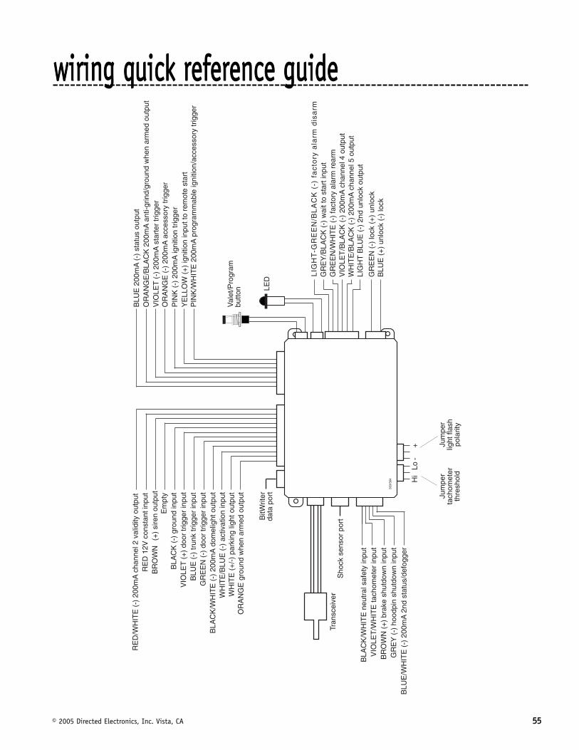
© 2005 Directed Electronics, Inc. Vista, CA 5555
��
�
�
� ��
����
���
����
���
����
���
��
���
����
� ��
��!"
� �#"
����
����
��
���
��$
%&�
��� ��
'�"(
��"�
��"�
���
�
�)��� ��
����
"��*
����
����
"���
�$
��
�
���
�+��
!��*
����
����
"���
�
$%&
���
���
���� ��
,,�
���
���*
����
*���
-�
��
%�
���
��
�
�$%�
./
���
�-�'�
��0
��#�
����
"*���
�
�)
�$%�
./
��� ��
�"���
��*�
����"
����
�
��
��
���
���� �-�
'���
0��#
���
����
��1
��%�
��$
%�.
/��� ��
,,�
��'
����
�#�2
����
���
�
��
��� �#�
'!���
���#
�'!
$%&
����
���#
�'!�
�� �#�
'!
1�#
���3
�� �
��+�
����
1��
%����
���
����
'���
����
�"���
�$
%�.
/��
���
���
�����#
�*�-
��0�
"���
�
$"��
�"���
����
����
�
4�5�
4�2
��
���
�$%�
./
��� ��
,,�
��'
����
�#�4
����
���
%�
���
$%&
���� ��
����
�#�'
!���
����
%��
6��
'!�*
��*�
����
��
$%�
./
���
���
��� ��
,,�
���
���#
" ��
����
���
�
��
��� ��
������"
���"�
���
$%&
���� ���
��!�
��"
���"�
���
1��
%���
�� ���
�����
" �
��"�
���
$%�
./
��� �
����
��"�
���
��
��0
$�
��
��
�*"
����
����
���
��
�7�1
�'��
*���
��"��
���
��
���
���
��� ��
,,�
��'
����
�#��
�(�#
"�"�0
����
���
$%&
���
,,�
���� �*
����
*���
����
��
�
�
�$%�
./
��,,
����
��"�
�"���
���
����
����
���
����
����
�1
��%�
���� ��,
,���*
������
���"
��
��
�
�
��� ��
,,�
���
''�*
*��0
���"
��
3�
/��� ��
,,�
��"
�"�"�
����"
��
)�
%%�
����
�" �"
�"���
"���
�����
���
����
*���
�3
�/
���
���
��,,
����
�� �
���
�+#�
�" �"
�"���
�''�
**��
0���"
��
8��
���
��'�
����
����
��*�
�#�
8��
���
#" ��
�-#�*
���
#��"�
0
��
%��
"
����
*'�"
(��
wwiirriinngg qquuiicckk rreeffeerreennccee gguuiiddee
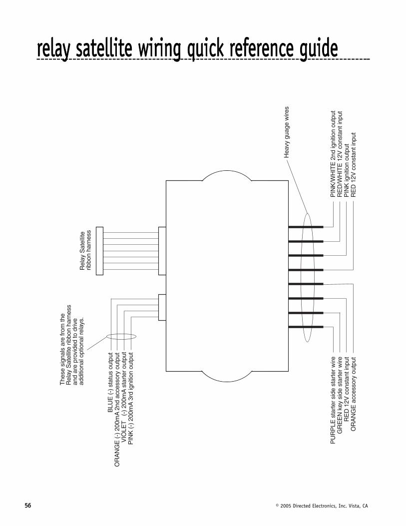
5566 © 2005 Directed Electronics, Inc. Vista, CA
3�
/���
��,,
���5
���"
�"�"�
����
����
1��
%���
���� ��
,,�
��*
�����
�����
���
��
�
����
��,,
����
����
''�*
*��0
����
���
$%&
����
�*��
��*�
����
��
��#
�0�6
���#
#"��
�"++�
����
���*
*
���
�7�1
�'��
*���
��"��
��3�
/�"
�"�"�
����
����
���
���
����7
�1�'
��*�
����"
����
3�
/��
���
���
���"
�"�"�
����
����
��
�
���
''�*
*��0
����
���
���
�7�1
�'��
*���
��"��
��
���
�!�0
�*"�
��*�
����
���"��
3&
�3%�
�*��
�����*
"���
*���
�����
"��
���*
��*"
��#
*���
��-��
����
��
�#�0
�6��
�##"�
���"+
+���
����
�**
����
����
���(
"���
�����
�"(�
���"
�"���
#����
"���
#���#
�0*9
���
(0�
�� �
��"��
*
rreellaayy ssaatteelllliittee wwiirriinngg qquuiicckk rreeffeerreennccee gguuiiddee


![5. Wiring Diagram - Subaru Forester. Wiring Diagram A: POWER SUPPLY ROUTING SU01-04A 12 6-3 [D5A0] WIRING DIAGRAM 5. Wiring Diagram SU01-04B 13 WIRING DIAGRAM [D5A0] 6-3 5. Wiring](https://img.pdfslide.net/doc/110x75/5aa205fe7f8b9a1f6d8cac3f/5-wiring-diagram-subaru-wiring-diagram-a-power-supply-routing-su01-04a-12.jpg)