Embed Size (px)
Citation preview
STATE OF CALIFORNIA
AIR RESOURCES BOARD
AIR MONITORING QUALITY ASSURANCE
VOLUME V
AUDIT PROCEDURES MANUAL FOR
AIR QUALITY MONITORING
APPENDIX E
THROUGH-THE-PROBE CRITERIA POLLUTANT
PERFORMANCE AUDIT PROCEDURES
MONITORING AND LABORATORY DIVISION
June 2015
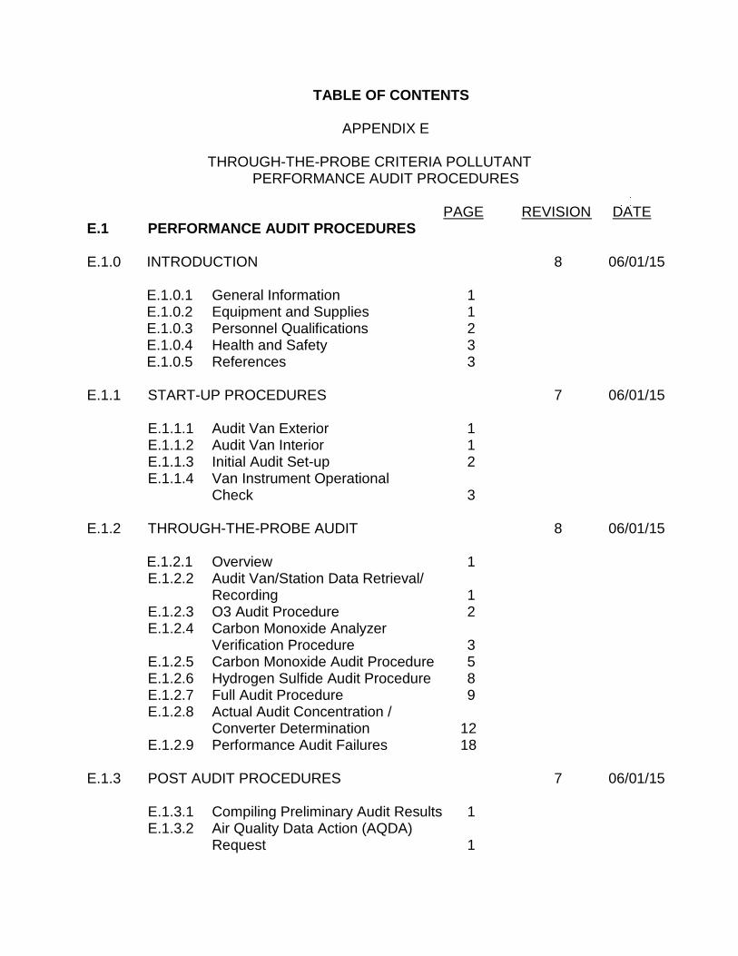
TABLE OF CONTENTS
APPENDIX E
THROUGH-THE-PROBE CRITERIA POLLUTANT PERFORMANCE AUDIT PROCEDURES
PAGE REVISION DATE E.1 PERFORMANCE AUDIT PROCEDURES E.1.0 INTRODUCTION 8 06/01/15 E.1.0.1 General Information 1 E.1.0.2 Equipment and Supplies 1 E.1.0.3 Personnel Qualifications 2 E.1.0.4 Health and Safety 3 E.1.0.5 References 3 E.1.1 START-UP PROCEDURES 7 06/01/15 E.1.1.1 Audit Van Exterior 1 E.1.1.2 Audit Van Interior 1 E.1.1.3 Initial Audit Set-up 2 E.1.1.4 Van Instrument Operational Check 3 E.1.2 THROUGH-THE-PROBE AUDIT 8 06/01/15 E.1.2.1 Overview 1 E.1.2.2 Audit Van/Station Data Retrieval/ Recording 1 E.1.2.3 O3 Audit Procedure 2 E.1.2.4 Carbon Monoxide Analyzer Verification Procedure 3 E.1.2.5 Carbon Monoxide Audit Procedure 5 E.1.2.6 Hydrogen Sulfide Audit Procedure 8 E.1.2.7 Full Audit Procedure 9 E.1.2.8 Actual Audit Concentration / Converter Determination 12 E.1.2.9 Performance Audit Failures 18 E.1.3 POST AUDIT PROCEDURES 7 06/01/15 E.1.3.1 Compiling Preliminary Audit Results 1 E.1.3.2 Air Quality Data Action (AQDA) Request 1
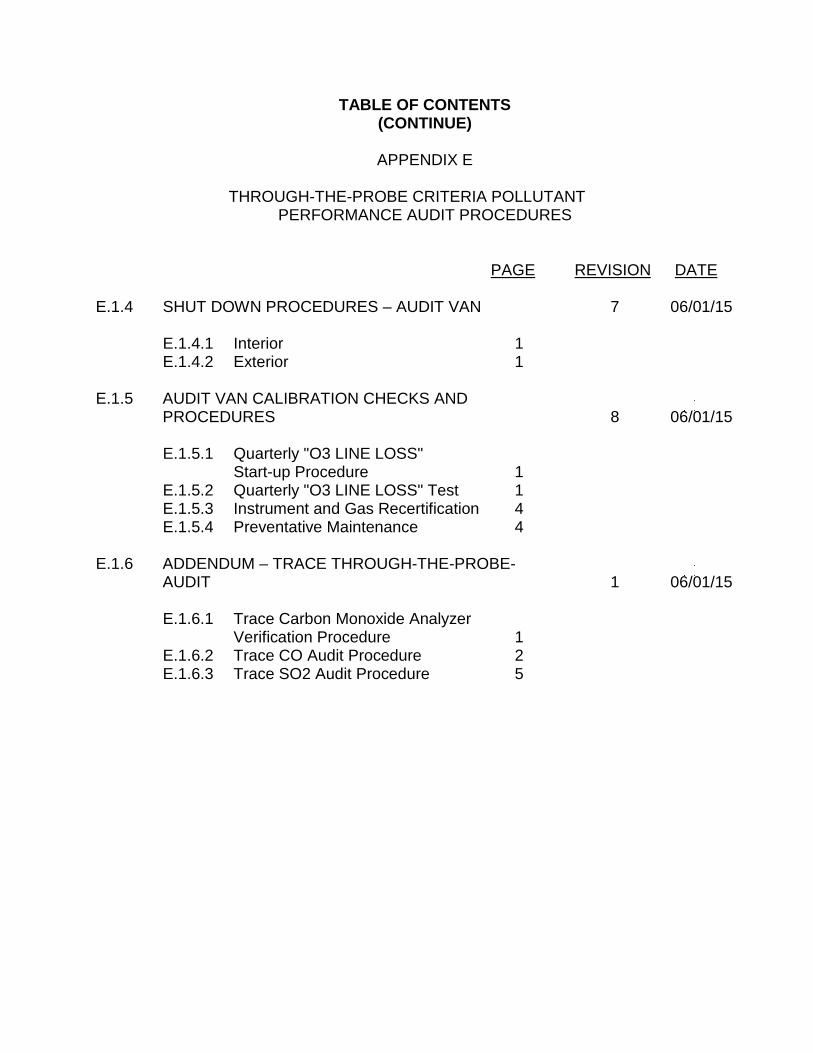
TABLE OF CONTENTS (CONTINUE)
APPENDIX E
THROUGH-THE-PROBE CRITERIA POLLUTANT
PERFORMANCE AUDIT PROCEDURES PAGE REVISION DATE E.1.4 SHUT DOWN PROCEDURES – AUDIT VAN 7 06/01/15 E.1.4.1 Interior 1 E.1.4.2 Exterior 1 E.1.5 AUDIT VAN CALIBRATION CHECKS AND
PROCEDURES 8 06/01/15 E.1.5.1 Quarterly "O3 LINE LOSS" Start-up Procedure 1 E.1.5.2 Quarterly "O3 LINE LOSS" Test 1 E.1.5.3 Instrument and Gas Recertification 4 E.1.5.4 Preventative Maintenance 4 E.1.6 ADDENDUM – TRACE THROUGH-THE-PROBE- AUDIT 1 06/01/15 E.1.6.1 Trace Carbon Monoxide Analyzer Verification Procedure 1 E.1.6.2 Trace CO Audit Procedure 2 E.1.6.3 Trace SO2 Audit Procedure 5
FIGURES
APPENDIX E
THROUGH-THE-PROBE CRITERIA POLLUTANT PERFORMANCE AUDIT PROCEDURES
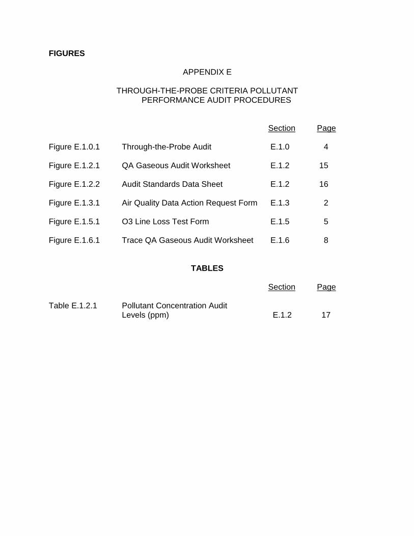
Section Page Figure E.1.0.1 Through-the-Probe Audit E.1.0 4 Figure E.1.2.1 QA Gaseous Audit Worksheet E.1.2 15 Figure E.1.2.2 Audit Standards Data Sheet E.1.2 16 Figure E.1.3.1 Air Quality Data Action Request Form E.1.3 2 Figure E.1.5.1 O3 Line Loss Test Form E.1.5 5 Figure E.1.6.1 Trace QA Gaseous Audit Worksheet E.1.6 8
TABLES Section Page Table E.1.2.1 Pollutant Concentration Audit
Levels (ppm) E.1.2 17
Volume V Section E.1.0 Revision 8 June 1, 2015 Page 1 of 4 E.1.0 INTRODUCTION E.1.0.1 GENERAL INFORMATION
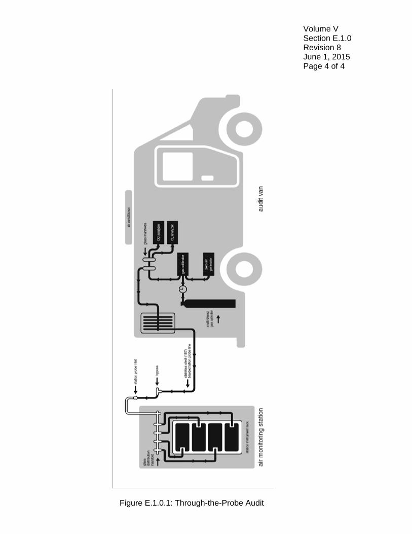
The Air Resources Board (ARB) Quality Assurance Section (QAS) is responsible for conducting through-the-probe (TTP) performance audits. These audits are required annually on all continuous gaseous analyzers in the ambient air monitoring network measuring for criteria pollutants. TTP audits of gaseous analyzers monitoring for O3 (O3), carbon monoxide (CO), nitrogen dioxide (NO2), hydrogen sulfide (H2S) and, sulfur dioxide (SO2) are conducted in accordance with U.S. Environmental Protection Agency (U.S. EPA) requirements (Title 40 Code of Federal Regulations, Part 58, Appendix A). These audits verify the accuracy of the gaseous analyzers and ensure the integrity of the entire sampling system. For the TTP audits, an audit van is driven by QAS staff to the ambient air monitoring station. Audit vans house the necessary instrumentation and equipment to allow the audit to be conducted under the same conditions as the station instruments. As depicted in Figure E.1.0.1, various concentrations of pollutant gases are delivered from the van, through a presentation line, into the station sampling probe. QAS compares the results obtained from the station analyzer to the known values generated in the van to determine accuracy.
The TTP audit methodology exposes deficiencies due to poor analyzer response, pollutant scavenging contaminants, and sampling system leaks. Deficiencies like these can cause the gaseous analyzers to fail an audit and possibly affect the quality of the ambient air data.
E.1.0.2 EQUIPMENT AND SUPPLIES
The current TTP audit system uses the following equipment:
1. Audit van with 240 VAC land-line and AC generator(s). 2. Voltage stabilized line conditioner, with battery backup. 3. Compressed gas cylinders traceable to National Institute of Standards
and Technology (NIST).
a. CO, 38-42 parts per million (ppm) (High CO), and 6-10 ppm (Low CO).
b. Ultrapure zero air.
Volume V Section E.1.0 Revision 8 June 1, 2015 Page 2 of 4
c. Superblend #1 (SB #1): CO, NO, NOX, and SO2. d. Superblend #2 (SB #2): CO and H2S. 4. Zero air generator. 5. Gas calibrator with an O3 generator.
6. O3 analyzer. 7. Carbon monoxide analyzer. 8. Nitrogen oxide analyzer.
NOTE: The nitrogen oxide analyzer is used for trouble-shooting and diagnostic purposes only. Therefore, it is not calibrated on a regular basis.
9. Presentation line is 150 feet of 3/8 inch, inside diameter, Teflon line
with stainless steel over-braiding and rubber casing with one to two feet of Teflon line attached to the end.
10. One to ten liters per minute by-pass rotometer and glass bypass tee.
11. Electronic barometer and temperature sensors. 12. Electronic chart recorder to document audit van temperature and audit
van gaseous concentrations. 13. Audit software to gather, calculate results, store audit data, and
generate a report upon completion of the audit.
E.1.0.3 PERSONNEL QUALIFICATION
All new ARB auditors undertake a one year training program that is documented and monitored by the QAS manager. The training includes in-office coursework, hands-on field experience conducting gaseous audits, and shadowing an experienced auditor for one year along with several in-field evaluations by the QAS manager. Initial training and certification of the National Performance Audit Program (NPAP) audit personnel is usually achieved through U.S. EPA’s federally implemented NPAP Field Scientist course. U.S. EPA reviews ARB’s training program annually for approval as an equivalent to U.S. EPA’s national certification and recertification courses. At least one senior ARB
Volume V Section E.1.0 Revision 8 June 1, 2015 Page 3 of 4
auditor is required to attend a phone recertification or equivalent training each year to receive information on any changes to U.S. EPA implemented NPAP that would need to be adopted by ARB to maintain the equivalency between the two programs.
E.1.0.4 HEALTH AND SAFETY
Refer to Standard Operating Procedures for Health and Safety at Air Monitoring Sites, Quality Assurance Section SOP AP.
E.1.0.5 REFERENCES
• U.S. Environmental Protection Agency, National Performance Audit Program for O3, SO2, NO2, and CO
• Title 40 Code of Federal Regulations Part 58, Appendix A • Quality Assurance Handbook, Volume II, Appendix D
Volume V Section E.1.0 Revision 8 June 1, 2015 Page 4 of 4
Figure E.1.0.1: Through-the-Probe Audit
Volume V Section E.1.1 Revision 7 June 1, 2015 Page 1 of 3 E.1.1 START-UP PROCEDURES E.1.1.1 AUDIT VAN EXTERIOR
Open the generator compartment door(s) and verify that the oil is in the "safe" operating range for each generator. Park the vehicle on level ground and shut off generator before checking generator engine oil. Unscrew the fill cap and wipe oil off the dip stick. Screw the cap back on, remove it and check the oil level on the dip stick. The oil level should be in the “safe” operation range between the FULL and ADD marks on the dip stick. Add oil as necessary.
E.1.1.2 AUDIT VAN INTERIOR
If additional warm-up of instruments is required prior to starting the generator(s), turn on equipment, in the following order; the voltage stabilized line conditioner with battery backup, the O3 analyzer, the CO analyzer, and the gas calibrator with O3 generator dilution unit. The voltage stabilized line conditioner with battery backup should operate these instruments for up to one and a half hours. It is not necessary to have zero air flow through the system during the warm-up period. 1. Make certain that the generator/land-line power source selector is in
the appropriate position (see generator operations manual). 2. Check that all circuit breakers are in "on" position. 3. Start generator(s) and warm up for five minutes prior to placing
electrical load on generator(s). If 240 VAC is available, use land-line power source in place of generator(s). After power source is stabilized place the power control switch in appropriate position (See specific procedures in audit van.)
4. Turn "on" the power to the voltage stabilized line conditioner with
battery backup (if not already on). 5. Turn "on" the power to the zero air generator (if not already on). 6. Turn "on" the power to the gas calibrator dilution unit (if not already
on). 7. The following analyzers are required for the audit(s) of the indicated
gases:
Volume V Section E.1.1 Revision 7 June 1, 2015 Page 2 of 3
a. O3: O3 analyzer.
b. CO, H2S, and SO2: CO analyzer.
c. NOX: O3, CO, and NOX analyzers.
NOTE: While the analyzers are in operation, the inside temperature of the van laboratory area must be maintained at 20-30 degrees Celsius (Quality Assurance Handbook Volume 2, Section 7.2.2). Check temperature routinely and adjust climate controls as necessary.
8. Turn "on" the power to the electronic chart recorder. 9. Allow a minimum warm-up time of one hour for the O3 analyzer and
two hours for the CO and NOX analyzers. E.1.1.3 INITIAL AUDIT SET-UP
1. Verify that the zero air generator and all instruments required for the
audit are operating properly.
2. Have the station operator take the station’s instrument data logger offline.
3. Press the "concentration" button on the front panel of the gas
calibrator. Check that ports one and two have been chosen for Superblend #1 and ports one and three for Superblend #2 on the calibrator and that the "Total Flow" indicates 16 liters per minute (lpm). Move cursor to "Target Gas" and enter "0.0" if it is not indicated. Press "Start,” then "Update" on the calibrator. Be sure the van's "Sample/Span" valve (3-way valve) is turned to the "Sample" position. Adjust the van's front manifold bypass to 0.3-0.4 lpm, if necessary.
4. Attach the presentation line to the station's gaseous probe inlet and
adjust the bypass to at least one liter per minute (lpm) for excess flow from the audit van.
NOTE: Connections will vary from station to station. Common
connections are: (1) through the calibration port on the stations glass inlet and (2) using the glass tee available in the audit van. Whatever the connection, be sure there is at least one lpm of bypass.
Volume V Section E.1.1 Revision 7 June 1, 2015 Page 3 of 3
5. Secure the presentation line to prevent movement during the audit. 6. Place safety cones around van as necessary.
E.1.1.4 VAN INSTRUMENT OPERATIONAL CHECK
After one hour, if any of the analyzer fails to meet operational standards consult the operator’s manual to review the analyzer’s test parameters and look up the troubleshooting guidelines. The operator’s manual, instrument operation manuals, and standard operating procedures are located on the van laptop desktop in the Forms and Worksheet folder. NOTE: The inlet pressure to the gaseous calibrator must be maintained
at 30 psi. Adjust the pressure regulator on the Zero air generator if this pressure is greater than ±10 percent from target pressure (see instrument manual).
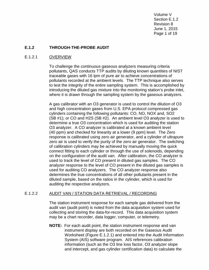
Volume V Section E.1.2 Revision 8 June 1, 2015 Page 1 of 19 E.1.2 THROUGH-THE-PROBE AUDIT E.1.2.1 OVERVIEW
To challenge the continuous gaseous analyzers measuring criteria pollutants, QAS conducts TTP audits by diluting known quantities of NIST traceable gases with 16 lpm of pure air to achieve concentrations of pollutants recorded at the ambient levels. The TTP technique also serves to test the integrity of the entire sampling system. This is accomplished by introducing the diluted gas mixture into the monitoring station’s probe inlet, where it is drawn through the sampling system by the gaseous analyzers.
A gas calibrator with an O3 generator is used to control the dilution of O3 and high concentration gases from U.S. EPA protocol compressed gas cylinders containing the following pollutants: CO, NO, NOX and, SO2 (SB #1); or CO and H2S (SB #2). An ambient level O3 analyzer is used to determine a true O3 concentration which is used for auditing the station O3 analyzer. A CO analyzer is calibrated at a known ambient level (40 ppm) and checked for linearity at a lower (9 ppm) level. The Zero response is calibrated using zero air generator, and a cylinder of ultrapure zero air is used to verify the purity of the zero air generator. The switching of calibration cylinders may be achieved by manually moving the quick connect fitting to each cylinder or through the use of solenoids, depending on the configuration of the audit van. After calibration, the CO analyzer is used to track the level of CO present in diluted gas samples. The CO analyzer response to the level of CO present in the diluted gas samples is used for auditing CO analyzers. The CO analyzer response also determines the true concentrations of all other pollutants present in the diluted sample, based on the ratios in the cylinder, which is used for auditing the respective analyzers.
E.1.2.2 AUDIT VAN / STATION DATA RETRIEVAL / RECORDING
The station instrument response for each sample gas delivered from the audit van (audit point) is noted from the data acquisition system used for collecting and storing the data-for-record. This data acquisition system may be a chart recorder, data logger, computer, or telemetry. NOTE: For each audit point, the station instrument response and van
instrument display are both recorded on the Gaseous Audit Worksheet (Figure E.1.2.1) and entered into the Audit Information System (AIS) software program. AIS references calibration information (such as the O3 line loss factor, O3 analyzer slope and intercept, and gas cylinder certification data) to calculate the
Volume V Section E.1.2 Revision 8 June 1, 2015 Page 2 of 19
van's true response at each audit point. AIS then calculates the percent difference between the two responses for each audit point and compares it with the acceptance criteria to indicate pass or fail.
With current technology, many monitoring stations are using electronic data loggers that store data at the site until collected on a set schedule. The data from the electronic data logger is handled in the same manner as the strip chart data, except that it is read directly from an electronic display at each audit level. The responses are recorded by the auditor on the audit worksheet and entered into the audit software program.
Some remote stations use a telemetry system. The telemetry system is updated every few minutes on dedicated phone lines. The data are averaged and stored in a centrally located computer. The station instrument responses are generally obtained by the site operator/technician calling for the analyzer responses. In some monitoring stations, this is accomplished by dialing the computer directly through a telephone modem. The response values are entered onto the station worksheet and into the audit van‘s laptop software program.
E.1.2.3 OZONE AUDIT PROCEDURE
1. Audit Point 1: Introduce zero air from the audit van to the station
through the presentation line. When the van and station readings are stable (ten minute chart trace and stability at or below 0.5 parts per billion [ppb]), record the responses on the Gaseous Audit Worksheet and in AIS with the laptop. This will be the first zero audit point. Consult table E.1.2.1 for the high, mid and low O3 audit points.
2. Audit Point 2: Cursor to O3 on the front panel of the calibrator and
enter the appropriate concentration for "Level 1" (high) audit point for O3 then press "Update.” When the van and station readings are stable, record the responses on the Gaseous Audit Worksheet and in AIS with the laptop.
NOTE: Make certain the calibrator updates after pressing the "Update"
button. Observe the "Target" and "Actual" O3 values on the front panel display of the calibrator. These values should be identical. If they are not, press "Update" again.
Volume V Section E.1.2 Revision 8 June 1, 2015 Page 3 of 19
NOTE: The gas calibrator with O3 generator is not calibrated on a regular basis; therefore, it may be necessary to adjust the target O3 values in order to get the desired concentration.
3. Audit Points 3 and 4: Follow the same procedure as "Audit Point 2"
for the "Level 2" and "Level 3" (mid and low) audit points. When the van and station readings are stable, record the responses on the Gaseous Audit Worksheet and in AIS with the laptop.
4. Audit Point 5: Cursor to O3 on the front panel of the calibrator and
enter zero (0.000 ppm) then press "Update.” When the van and station readings are stable, record the responses on the Gaseous Audit Worksheet and in AIS with the laptop.
5. Verify that all data entered into AIS matches the values on the
Gaseous Audit Worksheet. The second auditor should review and verify that the worksheet and AIS entries match.
6. Inform operator of preliminary audit results. In the event AIS identifies a
“fail” result follow Section E.1.2.9. PERFORMANCE AUDIT FAILURES. 7. Proceed with audit of other gaseous analyzer. If no further audits are
to be conducted follow Sections E.1.3 POST – AUDIT PROCEDURES and E.1.4 SHUT DOWN PROCEDURES – AUDIT VAN.
E.1.2.4 CARBON MONOXIDE ANALYZER VERIFICATION PROCEDURE
The audit van CO analyzer is used during a performance audit to analyze the amount of CO present in a diluted gas sample. Prior to each audit, of a gas other than O3 the CO analyzer is verified using zero air generator, ultrapure air, and NIST traceable CO gases at concentrations of approximately 9 ppm and 40 ppm. The CO analyzer is rechecked following the performance audit using the zero air generator, Ultrapure air, and a NIST traceable CO gas at 40 ppm. The pre-audit and post-audit CO analyzer responses are averaged to obtain true CO concentrations.
NOTE: If the CO analyzer drift exceeds 0.5 ppm for any of the verification
points the analyzer will require calibration. Refer to the operations manual for calibration procedures. The operator’s manual, instrument operation manuals, and standard operating procedures are located on the van laptop desktop in the Forms and Worksheet folder.
Volume V Section E.1.2 Revision 8 June 1, 2015 Page 4 of 19
NOTE: All van CO analyzer responses are to be entered into the laptop and on the Gaseous Audit Worksheet.
Two multi-port glass manifolds in the audit van are used during a performance audit. One manifold is used to supply the van instruments with zero air, Ultrapure zero air, and CO calibration gases, or diluted Superblend #1 gases. The additional manifold supplies the station with zero air or diluted Superblend #1 gases. A three-way valve is used to isolate the manifolds during verification of the van's CO analyzer. 1. The CO analyzer needs to be warmed-up for at least two hours prior
to calibration. The three-way valve should be in the "Sample" position prior to the audit.
2. If an O3 audit was conducted prior to the CO analyzer calibration, the
O3 analyzer may either be turned off or left on. If the O3 analyzer is turned off, readjust the flow to the bypass rotometer to 0.3-0.4 lpm.
3. Once the CO analyzer response to the zero air is stable, record the
result on the Gaseous Audit Worksheet under "CO Calibration.” If the response to zero air is not within ± 0.5 ppm of zero, calibrate the CO analyzer (refer to the CO analyzer operator’s manual).
4. When the response to zero air is stable, record the result on the Gaseous Audit Worksheet under "CO Calibration.”
5. Attach the quick connect on the "Span" line to the HIGH CO cylinder,
or if equipped, switch the High CO solenoid switch to the “on” position. Switch the 3-way valve to the "Span" position. Open the valve on the High CO gas cylinder and adjust the pressure regulator on the cylinder to 25 psi. Readjust the bypass to 0.3 to 0.4 lpm, using the appropriate needle valve.
6. Once the CO response is stable, record the result on the Gaseous
Audit Worksheet under "CO Calibration.” If the CO response is not within ± 0.5 ppm of the certified values listed on the High CO cylinder, calibrate the CO analyzer (refer to the CO analyzer operator’s manual).
7. Disconnect the "Span" line from the High CO and connect the quick
connect to the Low CO cylinder. Close the valve on the High CO
Volume V Section E.1.2 Revision 8 June 1, 2015 Page 5 of 19
cylinder. If the van is equipped with a solenoid, switch off the CO High, and then switch on the CO Low.
8. Open the valve on the Low CO gas cylinder and adjust the pressure
regulator to 25 psi. Readjust the bypass flow to 0.3 to 0.4 lpm, if necessary.
9. When the "Low CO" response is stable, record the result on the
Gaseous Audit Worksheet under "CO Calibration.” 10. Disconnect the "Span" line from the Low CO cylinder and connect the
quick connect to the ultrapure air cylinder. Close the valve on the Low CO cylinder. If the van is equipped with a solenoid, switch off the CO Low then switch on the ultrapure. Open the valve on the ultrapure air cylinder and adjust the pressure regulator to 25 psi. Readjust the bypass to 0.3 to 0.4 lpm, if necessary.
11. When the CO response is stable, record the result on the Gaseous
Audit Worksheet under "CO Calibration.”
12. Close the valve on the Ultrapure and disconnect the span line. If the van is equipped with a solenoid, put the switch for the Ultrapure in the “off” position.
13. Switch the 3-way valve back to the "Sample" position. Readjust the
bypass to 0.3 to 0.4 lpm, if necessary. 14. Enter all values into the laptop, if not already done. 15. To continue with other gaseous performance audits, refer to the
appropriate Section. E.1.2.5 CARBON MONOXIDE AUDIT PROCEDURE
1. The van gas calibrator should be in the "READY" mode ("CONC MODE" displayed on the lower left button). Press the "MAINTAIN PORTS" button. Enter "2" where the "Port" is indicated, press "ACCEPT." Confirm that the current quarter gas standards cylinder number and concentration have been entered into the calibrator. If the standards were not updated, enter the Superblend #1 concentrations for CO, NO, NOX, and SO2. Enter the cylinder identification number, using the "CYLINDER ID" button. Press the "EXIT" button twice to return to the "READY" mode.
Volume V Section E.1.2 Revision 8 June 1, 2015 Page 6 of 19
NOTE: Please refer to the operator’s manual if the van is equipped with a calibrator other than the Environics 9100. The operator’s manual, instrument operation manuals, and standard operating procedures are located on the van laptop desktop in the Forms and Worksheet folder.
2. Press the "CONC " button on the front panel of the calibrator. Verify
that the calibrator is displaying "MFC Port 2.” If not, cursor over and enter "2.” Cursor to "TARGET FLOW" and enter "16.0" if it is not displayed. Cursor to the "TARGET GAS" and enter "0.0" if it is not displayed.
3. Verification of the CO analyzer should be performed as outlined in
Section E.1.2.4. Consult Table E.1.2.1 for the highlighted audit points.
4. CO Audit Point 1: Record the zero air value on the Gaseous Audit
Worksheet and in AIS with the laptop. 5. Pressure regulator bleeding procedures. To bleed the
Superblend #1 pressure regulator, open the valve located at the NOX analyzer sample inlet for at least ten seconds prior to the audit. This procedure will evacuate any NO2 that has accumulated in the regulator.
6. Connect the line from the Environics 9100 port 2, to the
Superblend #1 regulator. Open the valve on the Superblend #1 cylinder and adjust the regulator pressure to 25 psi.
7. CO Audit Point 2: Using the arrow keys, move the cursor on the front
panel of the calibrator to "CO" and enter the concentration for the high CO audit point. Press the "UPDATE" button. When the van and station analyzer readings are stable, record the responses on the Gaseous Audit Worksheet and in AIS with the laptop. The station's instrument response for all CO audit points should be stable for a minimum of 10 minutes. NOTE: Verify that the calibrator updates after pressing the
"UPDATE" button. Observe the calibrator "TARGET" and "ACTUAL" gas values on the front panel display. These values should be the same (± 2 percent). If not, press "UPDATE" again.
Volume V Section E.1.2 Revision 8 June 1, 2015 Page 7 of 19
NOTE: The gas calibrator with O3 generator is not calibrated on a regular basis; therefore, it may be necessary to adjust the target CO values in order to get the desired concentration.
8. CO Audit Points 3 through 5: Repeat Step 7 for the "Middle," "Low,"
and "Post-Zero" audit points. When the readings are stable, record the responses on the Gaseous Audit Worksheet and in AIS with the laptop.
9. Switch the 3-way valve to the "Span" position. Connect the "Span"
line to the High CO regulator using the quick connect. If the audit van is equipped with a solenoid, switch the High CO to the “on” position. Open the High CO calibration cylinder and readjust the bypass to 0.3-0.4 lpm, if necessary. When the CO reading is stable, record the response on the Gaseous Audit Worksheet under "CO Calibration,” “Post-Audit CO Van Reading,” and in AIS with the laptop.
10. Switch the "Span" line to the ultrapure cylinder, close the valve on the
HIGH CO cylinder. If the audit van is equipped with a solenoid, switch the High CO to the “on” position. Open the "ultrapure" cylinder and readjust the bypass to 0.3-0.4 lpm, if necessary. When the reading is stable, record the response on the Gaseous Audit Worksheet under "CO Calibration,” “Post-Audit CO Van Reading,” and in AIS with the laptop.
11. Close the valve on the ultrapure cylinder. 12. Press "STOP" on the front panel of the calibrator, and then "EXIT" to
return the calibrator to the "READY" mode. 13. Verify that all data entered into AIS match the values on the Gaseous
Audit Worksheet. The second auditor should review and verify that the worksheet and AIS entries match.
14. Inform operator of preliminary audit results. In the event AIS identifies
a “fail” result follow Section E.1.2.9 PERFORMANCE AUDIT FAILURES.
15. Proceed with audit of other gaseous analyzer. If no further audits are
to be conducted follow Sections E.1.3 POST – AUDIT PROCEDURES and E.1.4 SHUT DOWN PROCEDURES – AUDIT VAN.
Volume V Section E.1.2 Revision 8 June 1, 2015 Page 8 of 19 E.1.2.6 HYDROGEN SULFIDE AUDIT PROCEDURE
1. The van gas calibrator should be in the "READY" mode ("CONC MODE" displayed on the lower left button). Press the "MAINTAIN PORTS" button. Enter the appropriate port number where "PORT" is indicated and press "ACCEPT.” Enter or verify the concentrations for H2S and CO. Enter the cylinder identification number, using the "CYLINDER ID" button. Press the "EXIT" button twice to return to the "READY" mode.
2. Press the "CONC MODE" button on the front panel of the calibrator.
Cursor to "TARGET FLOW" and enter "16.0" if not displayed. Cursor to "TARGET GAS" and enter "0.0" if not displayed. Press "UPDATE". Check that the 3-way valve is switched to "Sample."
3. Press the "START" button on the front panel of the Calibrator to
deliver zero air to the van and station instruments. Adjust the flow to the by-pass rotometer until 0.3-0.4 lpm is indicated.
4. Calibrate the CO analyzer as outlined in Section E.1.2.4. 5. Audit Point 1: Record the zero air generators’ reading on the
Gaseous Audit Worksheet and in the laptop. NOTE: The H2S analyzer may be audited on the 0-100 ppb or 0-200
ppb range (see Table E.1.2.1). 6. Audit Point 2: Cursor to "CO" and enter the "High" point concentration
in ppm for the applicable H2S analyzer range. Press the "UPDATE" button on the calibrator. When the van and station responses are stable, record them on the Gaseous Audit Worksheet and in AIS with the laptop. All H2S audit points should be stable for a minimum of 10 minutes.
NOTE: Verify that the calibrator updates after pressing the "UPDATE" button. Observe the calibrator "TARGET" and "ACTUAL" gas values on the front panel display. These values should be the same (± 2 percent). If not, press "UPDATE" again.
NOTE: The gas calibrator with O3 generator is not calibrated on a regular basis; therefore, it may be necessary to adjust the target CO values in order to get the desired concentration.
Volume V Section E.1.2 Revision 8 June 1, 2015 Page 9 of 19
7. Audit Points 3 and 4: Follow the same procedure as "Audit Point 2" for the "Middle" and "Low" audit points.
8. Audit Point 5: Cursor to "H2S" and enter zero (0.000 ppm) and press
"UPDATE.” When the van and station readings are stable, record the responses on the Gaseous Audit Worksheet and in AIS with the laptop.
9. Switch the 3-way valve to the "Span" position. Open the valve on the
"High CO" gas cylinder and attach the "Span" line to the regulator. If the audit van is equipped with a solenoid switch the High CO to the on position. Readjust the bypass flow to 0.3 to 0.4 lpm, if necessary. When the van CO reading is stable, record the response on the Gaseous Audit Worksheet under "CO Calibration," “Post-Audit CO Van Reading,” and in AIS with the laptop. Close the Valve on the High CO cylinder and disconnect the "Span" line.
10. Connect the "Span" line to the "ULTRAPURE" regulator and open the
valve. (If the audit van is equipped with a solenoid switch the High CO to the on position.) Readjust the bypass to 0.3-0.4 lpm, if necessary. When the van CO reading is stable, record the response on the Gaseous Audit Worksheet under "CO Calibration," “Post-Audit CO Van Reading,” and in AIS with the laptop.
11. When the station reading is stable, record the response on the
Gaseous Audit Worksheet. Press "STOP" on the front panel of the calibrator. Press "EXIT" to return the calibrator to the "READY" mode.
12. Verify that all data entered into AIS match the values on the Gaseous
Audit Worksheet. The second auditor should review and verify that the worksheet and AIS entries match.
13. Inform operator of preliminary audit results. In the event AIS identifies
a “fail” result follow Section E.1.2.9 PERFORMANCE AUDIT FAILURES.
14. Proceed with audit of other gaseous analyzer. If no further audits are
to be conducted follow Sections E.1.3 POST – AUDIT PROCEDURES and E.1.4 SHUT DOWN PROCEDURES – AUDIT VAN.
E.1.2.7 FULL AUDIT PROCEDURE
This procedure can be modified depending on the suite of analyzers present at the monitoring station. This procedure is detailed for CO, NOX,
Volume V Section E.1.2 Revision 8 June 1, 2015 Page 10 of 19
and SO2 analyzers in operation at ambient air monitoring stations. If all these analyzers are not present, corresponding audit points should be skipped. Consult Table E.1.2.1 for the audit points.
1. Place the van calibrator in the "READY" mode ("CONC MODE"
displayed on the lower left button) and press the "MAINTAIN PORTS" button. Enter the appropriate port number where "PORT" is indicated and press "ACCEPT.” Press the "EXIT" button twice to return to the "READY" mode.
2. Press the "CONC MODE" button on the front panel of the calibrator.
Cursor to "TARGET FLOW" and enter "16.0" lpm if not displayed. Cursor to "TARGET GAS" and enter "0.0" if not displayed. Press "UPDATE.” Check that the 3-way valve is switched to "Sample."
3. Press the "START" button on the front panel of the Calibrator to
deliver zero air to the van and station instruments. Adjust the flow to the bypass rotometer until 0.3-0.4 lpm is indicated.
4. If necessary calibrate the CO analyzer as outlined in Section E.1.2.4. 5. Audit Point 1: Record the CO value for zero-air on the Gaseous Audit
Worksheet and in AIS with the laptop. NOTE: Before starting Audit Point 2, check the operating range of the
station’s NO/NOX instrument. If the NO/NOX instrument is operating on a range less than 0-1 ppm, have the station operator disconnect the instrument from the manifold and cap the open manifold port. The instrument should be reconnected to the manifold when the target values for NO/NOX are within the instruments’ operating range. Also, if an SO2 analyzer is present, the NOX (if present) should be disconnected from the manifold, in a similar manner, for the SO2 high point.
6. Audit Point 2: Using the gas calibrator, target the value for CO which
corresponds to the high audit point of the station analyzer. Enter a “Target Gas” concentration. Press the "UPDATE" button on the front panel of the calibrator. When the audit van and station readings are stable, after a minimum of 10 minutes, record the responses on the Gaseous Audit Worksheet and in AIS with the laptop. NOX Titration: Without changing the CO concentration, move cursor to “C” on the front panel of the calibrator and enter 0.330 ppm. Press “Update.” When the van and station readings are stable, check that
Volume V Section E.1.2 Revision 8 June 1, 2015 Page 11 of 19
the resulting values fall within U.S. EPA range for the approved audit level. Record the response on the Gaseous Audit Worksheet and in AIS with the laptop.
7. Audit Point 3: Cursor to "O3" on the front panel of the calibrator and
enter "0.000.” Cursor to "TARGET" CO on the front panel of the calibrator and enter the value for CO which corresponds to the mid audit point of the station analyzer. Press "UPDATE" on the front panel of the calibrator. When the van and station readings are stable, record the responses on the Gaseous Audit Worksheet and in AIS with the laptop.
NOX Titration: Without changing the CO concentration, move cursor
to “O3” on the front panel of the calibrator and enter 0.150 ppm. Press “Update.” When the van and station readings are stable, check that the resulting values fall within U.S. EPA range for the approved audit level. Record the response on the Gaseous Audit Worksheet and in AIS with the laptop.
8. Audit Point 4: Cursor to "O3" on the front panel of the calibrator and
enter "0.000.” Cursor to "TARGET GAS" CO on the front panel of the calibrator and enter the value for CO which corresponds to the low audit point of the station analyzer. Press "UPDATE". When the van and station readings are stable, record the responses on the Gaseous Audit Worksheet and in AIS with the laptop. NOX Titration: Without changing the CO concentration, move cursor to “O3” on the front panel of the calibrator and enter 0.075 ppm. Press “Update.” When the van and station readings are stable, check that the resulting values fall within U.S. EPA range for the approved audit level. Record the response on the Gaseous Audit Worksheet and in AIS with the laptop.
9. Audit Point 5: Cursor to "O3" on the front panel of the calibrator and
enter "0.000.” Cursor to "TARGET GAS" CO on the front panel of the calibrator and enter 5.0 ppm. Press "UPDATE" on the front panel of the calibrator. When the van and station readings are stable, record the responses on the Gaseous Audit Worksheet and in AIS with the laptop.
10. Audit Point 6: Move the cursor on the front panel of the calibrator to
"TARGET GAS" CO, enter "0.0.” Press "UPDATE.” When the audit van and station responses are stable, record the results on the Gaseous Audit Worksheet and in AIS with the laptop.
Volume V Section E.1.2 Revision 8 June 1, 2015 Page 12 of 19
11. Switch the 3-way valve to the "Span" position. Connect the "Span"
line to the "HIGH" CO cylinder. Open the valve on the "HIGH CO" gas cylinder and adjust the bypass to 0.3-0.4 lpm, if necessary. When the van CO reading is stable, record the response on the van worksheet under "CO Calibration" and “Post-Audit CO Van Reading.”
12. Switch the "Span" line to the "ULTRAPURE" cylinder. Open the valve
on the "ULTRAPURE" gas cylinder and readjust the bypass to 0.3-0.4 lpm, if necessary. When the van CO reading is stable, record the response on the Gaseous Audit Worksheet under "CO Calibration" and “Post-Audit CO Van Reading.”
13. Switch the 3-way valve to the "Sample" position. Close the valves on all gas cylinders.
14. Press "STOP" on the front panel of the calibrator. Press "EXIT" to
return the calibrator to the "READY" mode. 15. Verify that all data entered into AIS match the values on the Gaseous
Audit Worksheet. The second auditor should review and verify that the worksheet and AIS entries match.
16. Inform operator of preliminary audit results. In the event AIS identifies
a “fail” result follow Section E.1.2.9 PERFORMANCE AUDIT FAILURES
17. Proceed with audit of other gaseous analyzer. If no further audits are
to be conducted follow Sections E.1.3 POST – AUDIT PROCEDURES and E.1.4 SHUT DOWN PROCEDURES – AUDIT VAN
E.1.2.8 ACTUAL AUDIT CONCENTRATION /CONVERTER EFFICIENCY
DETERMINATION
1. True O3 value for each audit point, for comparison with the station response, is calculated by applying a slope and intercept (derived from the biannual ARB Standards Laboratory certification) to the audit van O3 analyzer’s net display reading, and multiplying by one minus the O3 quarterly line loss correction factor (see Section E.1.5.1). True O3 (ppm) = [(Display – Zero Response) * Slope + Intercept] * (1 – Line Loss) where
• Display = O3 analyzer’s display response (ppm);
Volume V Section E.1.2 Revision 8 June 1, 2015 Page 13 of 19
• Zero Response = O3 analyzer’s zero response (ppm); • Slope = O3 analyzer’s slope; • Intercept = O3 analyzer’s intercept; and • Line Loss = O3 analyzer’s line loss correction factor.
The percent difference between actual audit (true O3) concentration and the station response is determined by Station Response – Actual Audit Percent Difference = --------------------------------------------- Actual Audit For each audit point, this percent difference is compared against the control limit criteria. If the percent difference is greater than ±10 percent the audit will result in a failure.
2. Actual concentrations for each gaseous pollutant except O3, at each
audit point, are determined by multiplying a dilution ratio with the concentration value of the pollutant in the Superblend cylinder. The dilution ratio and audit level concentrations are determined using the following formulae:
Dilution Ratio =
(Van CO – Van Zero) x CO Slope + CO Analyzer Intercept SB #1 or #2 CO Concentration Value
Actual audit values for NO, NOX, SO2, H2S (in ppb) = Dilution Ratio x SB #1 or SB #2 Concentration Value The percent difference between actual audit concentration and the station response is determined by Station Response – Actual Audit Percent Difference = --------------------------------------------- Actual Audit For each audit point, this percent difference is compared against the control limit criteria. If the percent difference is greater than ±15 percent the audit will result in a failure.
Volume V Section E.1.2 Revision 8 June 1, 2015 Page 14 of 19
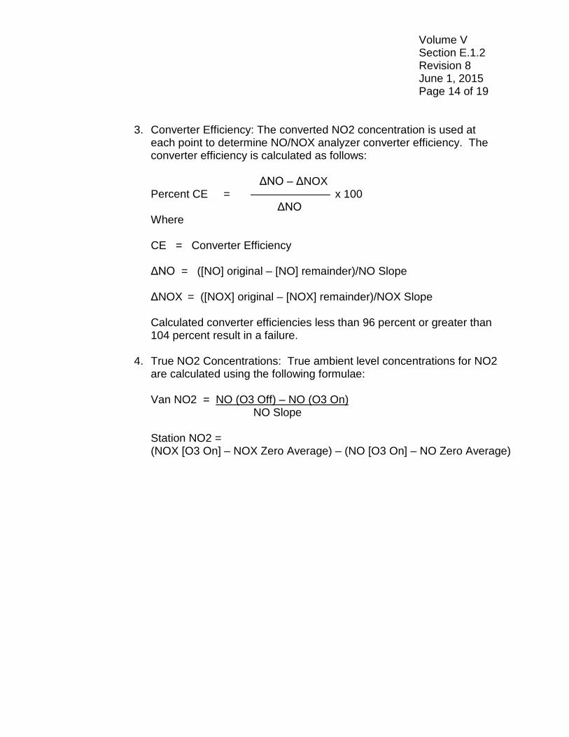
3. Converter Efficiency: The converted NO2 concentration is used at each point to determine NO/NOX analyzer converter efficiency. The converter efficiency is calculated as follows:
ΔNO – ΔNOX Percent CE = x 100 ΔNO Where CE = Converter Efficiency ΔNO = ([NO] original – [NO] remainder)/NO Slope ΔNOX = ([NOX] original – [NOX] remainder)/NOX Slope
Calculated converter efficiencies less than 96 percent or greater than 104 percent result in a failure.
4. True NO2 Concentrations: True ambient level concentrations for NO2
are calculated using the following formulae: Van NO2 = NO (O3 Off) – NO (O3 On) NO Slope
Station NO2 = (NOX [O3 On] – NOX Zero Average) – (NO [O3 On] – NO Zero Average)
Volume V Section E.1.2 Revision 8 June 1, 2015 Page 15 of 19
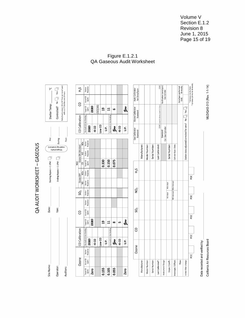
Figure E.1.2.1 QA Gaseous Audit Worksheet
Volume V Section E.1.2 Revision 8 June 1, 2015 Page 16 of 19
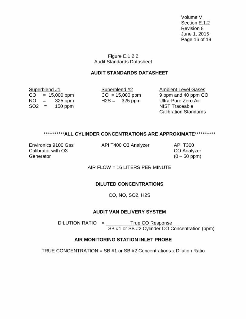
Figure E.1.2.2 Audit Standards Datasheet
AUDIT STANDARDS DATASHEET
Superblend #1 Superblend #2 Ambient Level Gases CO = 15,000 ppm CO = 15,000 ppm 9 ppm and 40 ppm CO NO = 325 ppm H2S = 325 ppm Ultra-Pure Zero Air SO2 = 150 ppm NIST Traceable Calibration Standards
***********ALL CYLINDER CONCENTRATIONS ARE APPROXIMATE***********
Environics 9100 Gas API T400 O3 Analyzer API T300 Calibrator with O3 CO Analyzer Generator (0 – 50 ppm)
AIR FLOW = 16 LITERS PER MINUTE
DILUTED CONCENTRATIONS
CO, NO, SO2, H2S
AUDIT VAN DELIVERY SYSTEM DILUTION RATIO = True CO Response SB #1 or SB #2 Cylinder CO Concentration (ppm)
AIR MONITORING STATION INLET PROBE
TRUE CONCENTRATION = SB #1 or SB #2 Concentrations x Dilution Ratio
Volume V Section E.1.2 Revision 8 June 1, 2015 Page 17 of 19
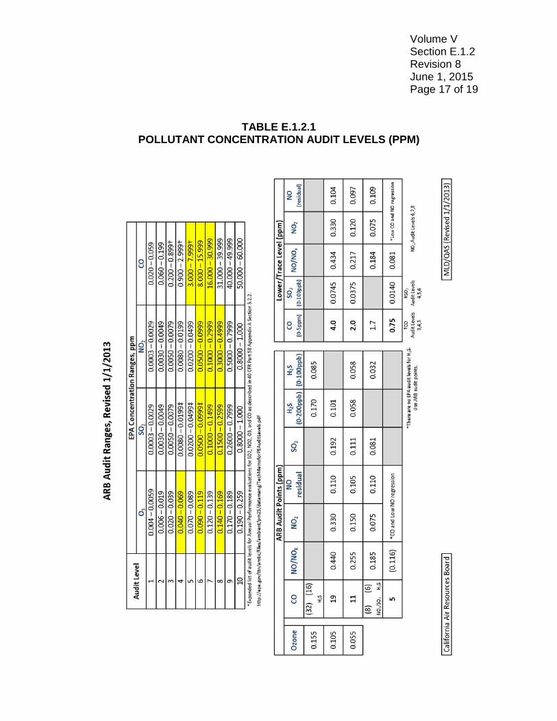
TABLE E.1.2.1 POLLUTANT CONCENTRATION AUDIT LEVELS (PPM)
Volume V Section E.1.2 Revision 8 June 1, 2015 Page 18 of 19 E.1.2.9 PERFORMANCE AUDIT FAILURES
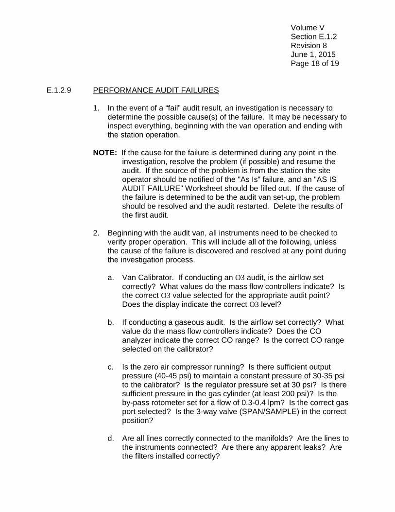
1. In the event of a “fail” audit result, an investigation is necessary to determine the possible cause(s) of the failure. It may be necessary to inspect everything, beginning with the van operation and ending with the station operation.
NOTE: If the cause for the failure is determined during any point in the
investigation, resolve the problem (if possible) and resume the audit. If the source of the problem is from the station the site operator should be notified of the "As Is" failure, and an "AS IS AUDIT FAILURE" Worksheet should be filled out. If the cause of the failure is determined to be the audit van set-up, the problem should be resolved and the audit restarted. Delete the results of the first audit.
2. Beginning with the audit van, all instruments need to be checked to
verify proper operation. This will include all of the following, unless the cause of the failure is discovered and resolved at any point during the investigation process.
a. Van Calibrator. If conducting an O3 audit, is the airflow set
correctly? What values do the mass flow controllers indicate? Is the correct O3 value selected for the appropriate audit point? Does the display indicate the correct O3 level?
b. If conducting a gaseous audit. Is the airflow set correctly? What
value do the mass flow controllers indicate? Does the CO analyzer indicate the correct CO range? Is the correct CO range selected on the calibrator?
c. Is the zero air compressor running? Is there sufficient output
pressure (40-45 psi) to maintain a constant pressure of 30-35 psi to the calibrator? Is the regulator pressure set at 30 psi? Is there sufficient pressure in the gas cylinder (at least 200 psi)? Is the by-pass rotometer set for a flow of 0.3-0.4 lpm? Is the correct gas port selected? Is the 3-way valve (SPAN/SAMPLE) in the correct position?
d. Are all lines correctly connected to the manifolds? Are the lines to
the instruments connected? Are there any apparent leaks? Are the filters installed correctly?
Volume V Section E.1.2 Revision 8 June 1, 2015 Page 19 of 19
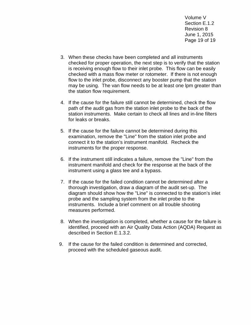
3. When these checks have been completed and all instruments checked for proper operation, the next step is to verify that the station is receiving enough flow to their inlet probe. This flow can be easily checked with a mass flow meter or rotometer. If there is not enough flow to the inlet probe, disconnect any booster pump that the station may be using. The van flow needs to be at least one lpm greater than the station flow requirement.
4. If the cause for the failure still cannot be determined, check the flow
path of the audit gas from the station inlet probe to the back of the station instruments. Make certain to check all lines and in-line filters for leaks or breaks.
5. If the cause for the failure cannot be determined during this
examination, remove the "Line" from the station inlet probe and connect it to the station’s instrument manifold. Recheck the instruments for the proper response.
6. If the instrument still indicates a failure, remove the "Line" from the
instrument manifold and check for the response at the back of the instrument using a glass tee and a bypass.
7. If the cause for the failed condition cannot be determined after a
thorough investigation, draw a diagram of the audit set-up. The diagram should show how the "Line" is connected to the station’s inlet probe and the sampling system from the inlet probe to the instruments. Include a brief comment on all trouble shooting measures performed.
8. When the investigation is completed, whether a cause for the failure is
identified, proceed with an Air Quality Data Action (AQDA) Request as described in Section E.1.3.2.
9. If the cause for the failed condition is determined and corrected,
proceed with the scheduled gaseous audit.
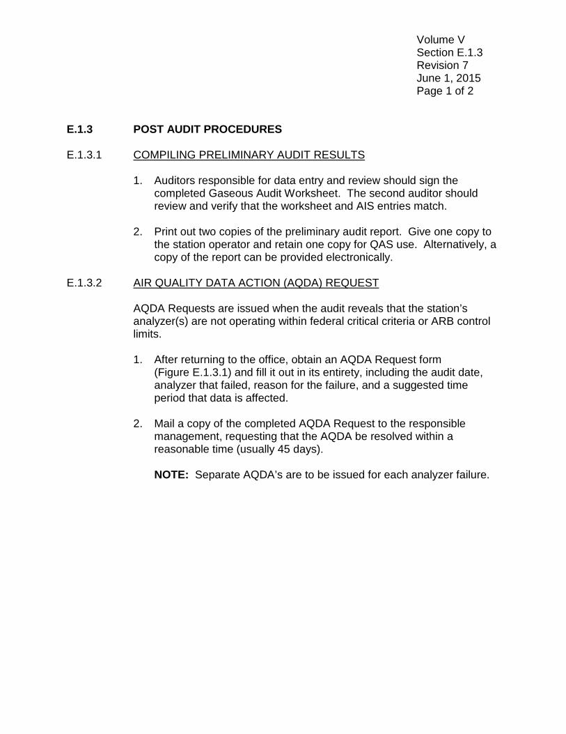
Volume V Section E.1.3 Revision 7 June 1, 2015 Page 1 of 2 E.1.3 POST AUDIT PROCEDURES E.1.3.1 COMPILING PRELIMINARY AUDIT RESULTS
1. Auditors responsible for data entry and review should sign the completed Gaseous Audit Worksheet. The second auditor should review and verify that the worksheet and AIS entries match.
2. Print out two copies of the preliminary audit report. Give one copy to
the station operator and retain one copy for QAS use. Alternatively, a copy of the report can be provided electronically.
E.1.3.2 AIR QUALITY DATA ACTION (AQDA) REQUEST
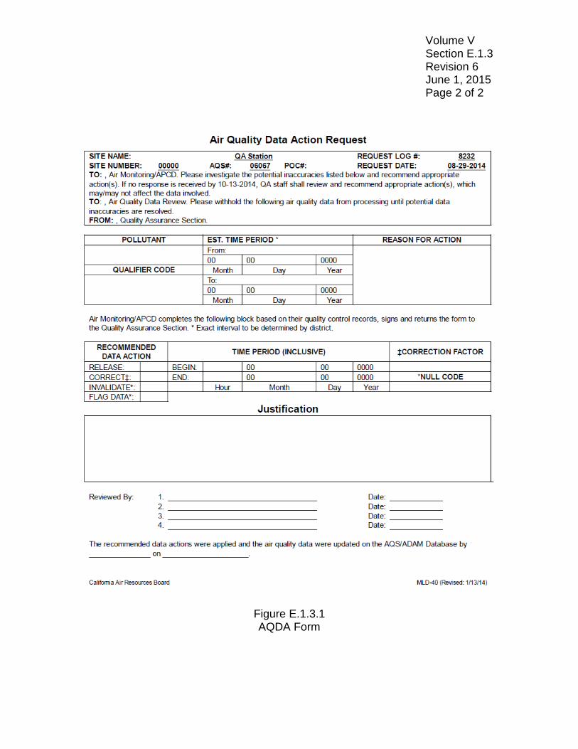
AQDA Requests are issued when the audit reveals that the station’s analyzer(s) are not operating within federal critical criteria or ARB control limits. 1. After returning to the office, obtain an AQDA Request form
(Figure E.1.3.1) and fill it out in its entirety, including the audit date, analyzer that failed, reason for the failure, and a suggested time period that data is affected.
2. Mail a copy of the completed AQDA Request to the responsible
management, requesting that the AQDA be resolved within a reasonable time (usually 45 days).
NOTE: Separate AQDA’s are to be issued for each analyzer failure.
Volume V Section E.1.3 Revision 6 June 1, 2015 Page 2 of 2
Figure E.1.3.1 AQDA Form
Volume V Section E.1.4 Revision 7 June 1, 2015 Page 1 of 1 E.1.4 SHUT DOWN PROCEDURES – AUDIT VAN E.1.4.1 INTERIOR
1. After printing the audit report, exit the computer AIS program and shut down the computer.
2. Turn off the power to the printer and chart recorder. 3. Turn off the power to the gas calibrator and applicable analyzers. 4. Turn off the power to the zero air system. 5. Close the valves on all compressed gas cylinders. 6. Turn off the power to the APC Smart UPS line conditioner. 7. Turn off the air conditioning units. 8. After shutting off all overhead lighting, turn off the generator(s).
E.1.4.2 EXTERIOR
1. Disconnect the presentation line from the station inlet and inform the operator that the station's data logger can be put back on line.
2. Reel the "Line" into the audit van and cap the end. Make certain the
end of the "Line" is placed into the "Line" cradle, and lock the hose reel into position.
3. Secure the ladder and safety cones. 4. Remove the wheel chocks.
Volume V Section E.1.5 Revision 8 June 1, 2015 Page 1 of 5 E.1.5 AUDIT VAN CALIBRATION CHECKS AND PROCEDURES E.1.5.1 QUARTERLY "OZONE LINE LOSS" TEST START-UP
The "O3 Line Loss" test is conducted quarterly to determine the actual O3 concentration being delivered to the station’s inlet probe. By analyzing the O3 concentration before and after the "Line,” it is possible to determine the actual amount of O3 loss attributed to the "Line.” This loss percentage is used to correct for "true" O3, so as not to bias audit results.
1. Plug in the audit van land-line or start the generator. 2. Make certain the land-line/generator switch is in the correct position. 3. Turn on the power to the APC Smart UPS, zero-air generator, gas
calibrator, O3 analyzer, and the chart recorder. 4. Make certain that the chart recorder is logging. 5. Record the date of the test, vehicle the test is being conducted in, and
the name of the person conducting the test. 6. Make certain that all the above instruments are "ON" and operating
properly. E.1.5.2 QUARTERLY "O3 LINE LOSS" TEST
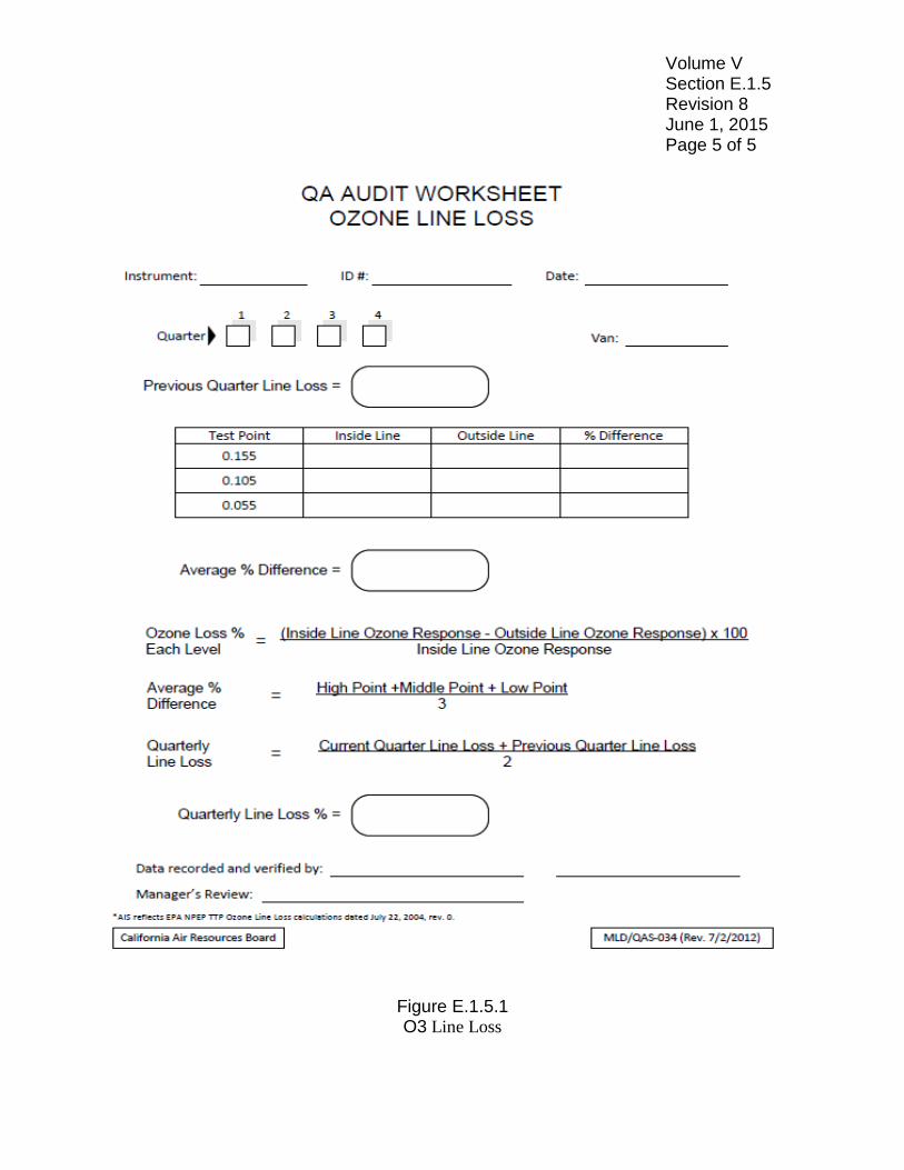
Two lines are used during the quarterly "O3 Line Loss" test. These will be referred to as the "Inside" and "Outside" lines. For determination of the line loss, information is recorded on the O3 Line Loss Audit Worksheet (Figure E.1.5.1).
INSIDE: Teflon line (1/4 inch OD) from the instrument port of the rear
manifold to the calibration port of the front manifold.
OUTSIDE: Stainless steel braided presentation line (150 feet long, 3/8 inch ID) with a needle valve, stainless steel tee, and one to two feet of Teflon line (1/4 inch OD).
NOTE: The van also uses two glass manifolds for gas distribution to
the van and station instruments. The "rear" manifold supplies audit gas concentrations to the station and a portion of the sample is supplied to the "front" manifold through a
Volume V Section E.1.5 Revision 8 June 1, 2015 Page 2 of 5
three-way valve which supplies the O3, NOX, and CO instruments.
1. Allow the zero-air generator, O3 analyzer, and the gas calibrator
(calibrator) to warm-up for at least one hour prior to conducting the "O3 Line Loss" test.
2. Uncap the audit van presentation line, remove the two-foot Teflon line
at the end of the presentation line, and attach the test equipment to the end of the presentation line.
3. With the calibrator in the "READY" mode ("CONC MODE" displayed
on the lower left button), press "CONC MODE" on the front panel of the calibrator. Using the arrow keys, cursor to "TOTAL FLOW" and enter "16.0" if not displayed. Cursor to "TARGET GAS" CO and enter "0.0" if not displayed. Cursor to "O3" and enter "0.000" if not displayed. Switch the 3-way valve to the "Sample" position. Press the "START" button on the front panel of the calibrator to deliver zero air.
4. With the "Inside" line connected to the front manifold, adjust the flow
to the rotometer until a by-pass flow of 0.3-0.4 lpm is indicated. When the O3 analyzer has a stable zero, record the value.
5. Disconnect the "Inside" line from the front manifold and connect the
"Outside" line. Using the needle valve on the test equipment, adjust the flow to the rotometer until a 0.3-0.4 lpm by-pass flow is indicated. When the O3 analyzer has a stable zero, record the value.
6. Cursor down to "O3" on the front panel of the calibrator and enter
"0.155" and press "UPDATE.” Allow sufficient time for a stable trace and record the O3 analyzer response.
7. Disconnect the "Outside" line and reconnect the "Inside" line.
Readjust the by-pass flow if necessary. Allow sufficient time for a stable trace and record the O3 analyzer response.
8. Cursor to "O3" on the front panel of the calibrator and enter "0.105"
and press "UPDATE.” Record the value when the O3 analyzer has a stable reading.
9. Disconnect the "Inside" line and reconnect the "Outside" line.
Volume V Section E.1.5 Revision 8 June 1, 2015 Page 3 of 5
10. Cursor to "O3" on the front panel of the calibrator and enter "0.055" and press "UPDATE.” Record the value when the O3 analyzer has a stable reading.
11. Disconnect the "Outside" line and reconnect the "Inside" line. Record
the value when the O3 analyzer has a stable reading.. 12. Cursor to "O3" on the front panel of the calibrator and enter "0.000"
and press "UPDATE.” Record the value when the O3 analyzer has a stable reading.
13. Disconnect the "Inside" line and reconnect the "Outside" line. Record
the value when the O3 analyzer has a stable reading. 14. Disconnect the "Outside" line and reconnect the "Inside" line. 15. Calculate the Quarterly O3 Line Loss using the following formulae:
NOTE: Before calculating "Quarterly O3 Line Loss,” subtract zero response at each test level.
O3 line loss percent for each level = Inside Line Response – Outside Line Response
Inside Line Response Average percent difference =
Test Level 1 + Test Level 2 + Test Level 3 3
Line Loss percent = Previous Quarter Loss + Current Quarter Loss
2
WARNING: If the current quarter line loss exceeds the previous quarter line loss by more than two percent, repeat the O3 line loss test. Condition the presentation line by running 0.500 ppm O3 through the line, if necessary.
16. Remove the O3 line loss test equipment from the presentation line.
Reconnect the two-foot Teflon line, cap it, and wind the presentation line back on the hose reel. Place the end of the "Line" in the hose cradle, and lock the hose reel in place.
Volume V Section E.1.5 Revision 8 June 1, 2015 Page 4 of 5 E.1.5.3 INSTRUMENT AND GAS RECERTIFICATION
1. O3 analyzer and transfer standard– The ARB Standards Laboratory re-certifies the UV Photometer against a Standard Reference Photometer at least semi-annually. The slope and intercept derived from the recertification are used in the calculation of audit van "True" O3 values.
2. Compressed Gases – The High CO (40 ppm), Low CO (9 ppm), and
SB #1 cylinders are certified on an annual basis in accordance with the U.S. EPA National Performance Audit Program requirement. SB #2 cylinders are certified in accordance with manufacturer recommendations.
E.1.5.4 PREVENTATIVE MAINTENANCE
1. At the end of each quarter perform 90-day Biannual Inspection of Terminals (BIT) and maintenance on all audit vans.
3. Replace particulate filters on all gaseous analyzers quarterly or as needed.
4. Check test parameter functions on all gaseous analyzer quarterly or as needed.
5. Leak check all analyzers annually or as needed.
Volume V Section E.1.5 Revision 8 June 1, 2015 Page 5 of 5
Figure E.1.5.1 O3 Line Loss
Volume V Section E.1.6 Revision 1 June 1, 2015 Page 1 of 8
E.1.6 ADDENDUM – TRACE THROUGH-THE-PROBE-AUDIT E.1.6.1 TRACE CARBON MONOXIDE ANALYZER VERIFICATION PROCEDURE
The audit van trace CO analyzer is used during a performance audit to analyze the amount of CO present in a trace diluted gas sample. Prior to each trace audit the trace CO analyzer is verified using zero air generator, ultrapure air, and NIST traceable CO gases at concentrations of approximately 1 and 4 ppm. The trace CO analyzer is rechecked following the performance audit using the zero air generator, Ultrapure air, and a NIST traceable CO gases at about 1 and 4 ppm. The pre-audit and post-audit CO analyzer responses are averaged to obtain true CO concentrations.
NOTE: Manual calibration with zero and span values should be
performed prior to trace CO verification. Refer to the operations manual for calibration procedures.
NOTE: All van trace CO analyzer responses are to be entered in AIS and
on the Trace Gaseous Audit Worksheet (Figure E1.6.1).
Two multi-port glass manifolds in the audit van are used during a performance audit. One manifold is used to supply the van instruments with zero air, Ultrapure zero air, and CO calibration gases, or diluted Superblend #1 gases. The additional manifold supplies the station with zero air or diluted Superblend #1 gases. A three-way valve is used to isolate the manifolds during verification of the van's trace CO analyzer. 1. The trace CO analyzer needs to be warmed-up for at least two hours
prior to calibration. The three-way valve should be in the "Sample" position prior to the audit.
2. Once the trace CO analyzer response to the zero air is stable, record
the result on the Trace Gaseous Audit Worksheet under "CO Calibration.”
3. Open the valve on the High CO gas cylinder and adjust the pressure regulator on the cylinder to 5 psi. Switch the High CO solenoid to the
Volume V Section E.1.6 Revision 1 June 1, 2015 Page 2 of 8
“on” position. Switch the 3-way valve to the "Span" position. Readjust the bypass to 0.3 to 0.4 lpm, using the appropriate needle valve.
4. Once the CO response is stable, record the result on the Gaseous
Audit Worksheet under "CO Calibration.” 5. Switch off the CO High, and then switch on the CO Low. 6. Open the valve on the Low CO gas cylinder and adjust the pressure
regulator to 5 psi. Readjust the bypass flow to 0.3 to 0.4 lpm, if necessary.
7. When the "Low CO" response is stable, record the result on the
Gaseous Audit Worksheet under "CO Calibration.” 8. Switch off the CO Low then switch on the ultrapure. Open the valve
on the ultrapure air cylinder and adjust the pressure regulator to 5 psi. Readjust the bypass to 0.3 to 0.4 lpm, if necessary.
9. When the CO analyzer response is stable, record the Ultrapure value
on the Gaseous Audit Worksheet under "CO Calibration.”
10. Switch the Ultrapure solenoid to the “off” position. 11. Switch the 3-way valve back to the "Sample" position. Readjust the
bypass to 0.3 to 0.4 lpm, if necessary. 12. Enter all values into the laptop, if not already done. 13. To continue with other gaseous performance audits, refer to the
appropriate Section. E.1.6.2 TRACE CARBON MONOXIDE AUDIT PROCEDURE
1. The van gas calibrator should be in the "READY" mode ("CONC MODE" displayed on the lower left button). Press the "MAINTAIN PORTS" button. Enter "2" where the "Port" is indicated, press "ACCEPT." Confirm that the current quarter gas standards cylinder number and concentration have been entered into the calibrator. If the standards were not updated, enter the Superblend #1 concentrations for CO, NO, NOX, and SO2. Enter the cylinder identification number, using the "CYLINDER ID" button. Press the "EXIT" button twice to return to the "READY" mode.
Volume V Section E.1.6 Revision 1 June 1, 2015 Page 3 of 8
NOTE: Please refer to the operator’s manual if the van is equipped
with a calibrator other than the Environics 9100. 2. Press the "CONC " button on the front panel of the calibrator. Verify
that the calibrator is displaying "MFC Port 2.” If not, cursor over and enter "2.” Cursor to "TARGET FLOW" and enter "16.0" if it is not displayed. Cursor to the "TARGET GAS" and enter "0.0" if it is not displayed.
3. Verification of the CO analyzer should be performed as outlined in
Section E.1.6.1. Consult Table E.1.2.1 for trace CO audit points. 4. Trace CO Audit Point 1: Record the zero air value on the Trace
Gaseous Audit Worksheet and in AIS with the laptop. 5. Pressure regulator bleeding procedures. To bleed the
Superblend #1 pressure regulator, open the valve located at the back of the calibrator inlet for at least twenty seconds prior to the audit. This procedure will evacuate any NO2 that has accumulated in the regulator.
6. Open the valve on the Superblend #1 cylinder and adjust the regulator
pressure to 25 psi. 7. Trace CO Audit Point 2: Using the arrow keys, move the cursor on
the front panel of the calibrator to "CO" and enter the concentration for the high CO audit point. Press the "UPDATE" button. When the van and station analyzer readings are stable, record the responses on the Trace Gaseous Audit Worksheet and in AIS with the laptop. The station's instrument response for all CO audit points should be stable for a minimum of 10 minutes. NOTE: Verify that the calibrator updates after pressing the
"UPDATE" button. Observe the calibrator "TARGET" and "ACTUAL" gas values on the front panel display. These values should be the same (± 2 percent). If not, press "UPDATE" again.
NOTE: The gas calibrator with O3 generator is not calibrated on a
regular basis; therefore, it may be necessary to adjust the target CO values in order to get the desired concentration.
Volume V Section E.1.6 Revision 1 June 1, 2015 Page 4 of 8
8. Trace CO Audit Points 3 through 5: Repeat Step 7 for the "Middle," "Low," and "Post-Zero" audit points. When the readings are stable, record the responses on the Gaseous Audit Worksheet and in AIS with the laptop.
9. Switch the 3-way valve to the "Span" position. Switch the High CO
solenoid to the “on” position. Open the High CO calibration cylinder and readjust the bypass to 0.3-0.4 lpm, if necessary. When the CO reading is stable, record the response on the Gaseous Audit Worksheet under "CO Calibration,” “Post-Audit CO Van Reading,” and in AIS with the laptop.
10. Switch the Low CO solenoid to the “on” position. Open the Low CO
calibration cylinder and readjust the bypass to 0.3-0.4 lpm, if necessary. When the CO reading is stable, record the response on the Gaseous Audit Worksheet under "CO Calibration,” “Post-Audit CO Van Reading,” and in AIS with the laptop.
11. Switch the High CO to the “on” position. Open the "ultrapure" cylinder
and readjust the bypass to 0.3-0.4 lpm, if necessary. When the reading is stable, record the response on the Gaseous Audit Worksheet under "CO Calibration,” “Post-Audit CO Van Reading,” and in AIS with the laptop.
12. Close the valve on the ultrapure cylinder. 13. Press "STOP" on the front panel of the calibrator, and then "EXIT" to
return the calibrator to the "READY" mode. 14. Verify that all data entered into AIS match the values on the Gaseous
Audit Worksheet. The second auditor should review and verify that the worksheet and AIS entries match.
15. Inform operator of preliminary audit results. In the event AIS identifies
a “fail” result follow Section E.1.2.9 PERFORMANCE AUDIT FAILURES.
16. Proceed with audit of other gaseous analyzer. If no further audits are
to be conducted follow Sections E.1.3 POST – AUDIT PROCEDURES and E.1.4 SHUT DOWN PROCEDURES – AUDIT VAN.
Volume V Section E.1.6 Revision 1 June 1, 2015 Page 5 of 8 E.1.6.3 TRACE SO2 AUDIT PROCEDURE
This procedure outlines a trace SO2 audit at ambient air monitoring station. Consult Table E.1.2.1 for the trace SO2 audit points. 1. Place the van calibrator in the "READY" mode ("CONC MODE"
displayed on the lower left button) and press the "MAINTAIN PORTS" button. Enter the appropriate port number 2 where "PORT" is indicated and press "ACCEPT.” Press the "EXIT" button twice to return to the "READY" mode.
2. Press the "CONC MODE" button on the front panel of the calibrator.
Cursor to "TARGET FLOW" and enter "16.0" lpm if not displayed. Cursor to "TARGET GAS" and enter "0.0" if not displayed. Press "UPDATE.” Check that the 3-way valve is switched to "Sample."
3. Press the "START" button on the front panel of the Calibrator to
deliver zero air to the van and station instruments. Adjust the flow to the bypass rotometer until 0.3-0.4 lpm is indicated.
4. If necessary calibrate the trace CO analyzer as outlined in Section
E.1.6.1. 5. Audit Point 1: Record the trace CO value for zero-air on the Gaseous
Audit Worksheet and in AIS with the laptop.
6. Audit Point 2: Using the gas calibrator, target the value for trace CO which corresponds to the high audit point of the station analyzer. Enter a “Target Gas” concentration. Press the "UPDATE" button on the front panel of the calibrator. When the audit van and station readings are stable, after a minimum of 10 minutes, record the responses on the Gaseous Audit Worksheet and in AIS with the laptop.
7. Audit Point 3: Cursor to "TARGET" CO on the front panel of the
calibrator and enter the value for trace CO which corresponds to the mid audit point of the station analyzer. Press "UPDATE" on the front panel of the calibrator. When the van and station readings are stable, record the responses on the Gaseous Audit Worksheet and in AIS with the laptop.
8. Audit Point 4: Cursor to "TARGET GAS" CO on the front panel of the
calibrator and enter the value for trace CO which corresponds to the
Volume V Section E.1.6 Revision 1 June 1, 2015 Page 6 of 8
low audit point of the station analyzer. Press "UPDATE". When the van and station readings are stable, record the responses on the Gaseous Audit Worksheet and in AIS with the laptop.
9. Audit Point 6: Move the cursor on the front panel of the calibrator to
"TARGET GAS" CO, enter "0.0.” Press "UPDATE.” When the audit van and station responses are stable, record the results on the Trace Gaseous Audit Worksheet and in AIS with the laptop.
10. Switch the 3-way valve to the "Span" position. Open the valve on the
"HIGH CO" gas cylinder and adjust the bypass to 0.3-0.4 lpm, if necessary. When the van CO reading is stable, record the response on the Trace Gaseous Audit Worksheet under "CO Calibration," “Post-Audit CO Van Reading,” and in AIS with the laptop.
11. Switch the Low CO solenoid to the “on” position. Open the Low CO
calibration cylinder and readjust the bypass to 0.3-0.4 lpm, if necessary. When the van CO reading is stable, record the response on the Trace Gaseous Audit Worksheet under "CO Calibration,” “Post-Audit CO Van Reading,” and in AIS with the laptop.
12. Switch the "Span" line to the "ULTRAPURE" cylinder. Open the valve
on the "ULTRAPURE" gas cylinder and readjust the bypass to 0.3-0.4 lpm, if necessary. When the van CO reading is stable, record the response on the Trace Gaseous Audit Worksheet under "CO Calibration" and “Post-Audit CO Van Reading.”
13. Switch the 3-way valve to the "Sample" position. Close the valves on
all gas cylinders. 14. Press "STOP" on the front panel of the calibrator. Press "EXIT" to
return the calibrator to the "READY" mode. 15. Verify that all data entered into AIS match the values on the Gaseous
Audit Worksheet. The second auditor should review and verify that the worksheet and AIS entries match.
16. Inform operator of preliminary audit results. In the event AIS identifies
a “fail” result follow Section E.1.2.9 PERFORMANCE AUDIT FAILURES

Volume V Section E.1.6 Revision 1 June 1, 2015 Page 7 of 8
17. Proceed with audit of other gaseous analyzer. If no further audits are
to be conducted follow Sections E.1.3 POST – AUDIT PROCEDURES and E.1.4 SHUT DOWN PROCEDURES – AUDIT VAN.
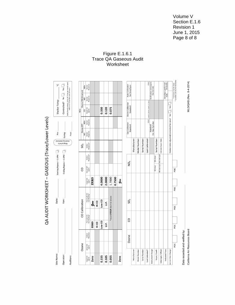
Volume V Section E.1.6 Revision 1 June 1, 2015 Page 8 of 8
Figure E.1.6.1
Trace QA Gaseous Audit Worksheet