Embed Size (px)
Citation preview
STATIC LATERAL- DIRECTIONAL STABILITY CHARACTERISTICS
OF FIVE CONTEMPORARY AIRPLANE MODELS FROM
WIND-TUNNEL TESTS AT HIGH SUBSONIC
AND SUPERSONIC SPEEDS
By Willard G. Smith and Louis H. Ball 4 Sd' Ames Aeronautical Laboratory A
Moffett Field, Calif.
GPO PRICE $ AOTHOKITl
Mlcrofiche (M F)
ff 653 July 65
NATIONAL ADVISORY COMMITTEE FOR AERONAUTICS
WASHINGTON January 4,1956
https://ntrs.nasa.gov/search.jsp?R=19660010446 2018-07-10T12:02:07+00:00Z
3
0 . 'I
I'
~ re- -
NATIONAL ADVISORY COMMITTEE FOR AERONAUTICS w 20 _ . . RESEARCH MEMORANDUM
E i b I C LATERAL-DIRECTIONAL STABILITY CHARACTERISTICS .s
OF FIVE CONTENPORARY AIRPLANE MODELS FRO
WIND-TUNNEL TESTS AT HIGH SUBSONIC -7
AND SUPERSONIC SPEEDS-\ Gl GI
This report presents the static lateral-directional stability charac- teristics of several airplane models recently investigated which cover many of the geometric arrangements of high-speed airplane components of current interest. The measured aerodynamic qualities afford information on the aerodynamic derivatives required for calculation of airplane motions. The results are presented for a subsonic Mach number of 0.9 and for super- sonic Mach nunhers ranging from 1.2 to 1.9. tests ranged from 1 to 4 million based on the mean aerodynamic chord.
The Reynolds numbers of the
Discussion of the results is limited to the most pertinent aerodynamic phenomena contributing to the lateral-directional characteristics of each airplane type. The directional stability of all the models deteriorated with increasing angle of attack and increasing Mach number. Interference effects are shown to have a strong influence upon the vertical-tail effec- tiveness and, consequently, upon the directional sia'vility. Tliese effects are, for the most part, associated with complex flow involving vorticity or shock waves and are, therefore, difficult to analyze. In order to expedite publication no analysis has been made. some insight into the basic phenomena involved.
The data, however, serve to give
INTRODUCTION
Much attention is being focused on the lateral-directional stability The low-aspect-ratio of aircraft capable of flight at supersonic speeds.
wings and high-fineness-ratio bodies necessary to satisfy the low drag requirements of these airplanes have increased the complexity of the aero- dynamic problems encountered in their design. The use of far rearward
2
center-of-gravity locations with the consequent short tail arms further aggravates the situation. available for a study of these problems. existing pertinent data was undertaken with a view to&rd supplying some of this needed information.
Only a small amount of aerodynamic data is 8' Por'thisreagon, a review of
It is the purpose of this report to summarize some of the current These data information regarding lateral-directional characteristics.
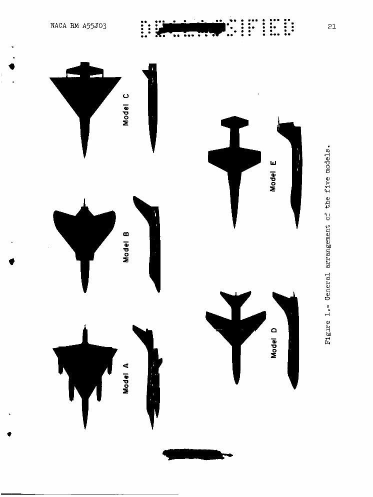
the most part, from developmental wind-tunnel tests ode1 configurations as requested by the military e models for which results are presented (see fig. 1) fairly representative of current design philosophy
~~
concerning airplanes capable- of flight speeds of the order of twice the speed of sound.
NOTATION
A l l results are presented in standard NACA coefficient form with the forces referred to the wind axes and the moments referred to the stability axes. In the stability system the Z axis lies in the plane of symmetry and is normal to the relative wind; the Y axis is normal to the plane of symmetry; and the X axis is normal to the Y and Z axes. definitions used in this report are as follows:
yawing moment C n
(See table I for moment center locations.) The notation and
yawing-moment coefficient, qSb
cross-wind force cross-wind-force coefficient, qs CC
rolling moment rolling-moment coefficient, qSb
C l
rate of change of yawing-moment coefficient with sideslip cnP angle, per deg
rate of change of cross-wind-force coefficient with sideslip angle, per deg ccP
rate of- change of rolling-moment coefficient with sideslip angle, per deg c z P
yawing-moment coefficient measured at a sideslip angle of Cn P -
5 O divided by 5', per deg
. . i
c
'.
cross-wind-force coefficient measured at a sideslip angle of 5' divided by 5 O , per deg
rolling-moment coefficient measured at a sideslip angle of 5' divided by 5 O , per deg
free-stream Mach number
total wing area including the area formed by extending the.' '
leading and trailing edges to the vertical plane of symmetry, sq ft
wing span, ft
mean aerodynamic chord of the wing, ft
ratio of mass flow through duct to mass flow through an equivalent stream tube in the free stream
free-stream d-ynmLic pressure, l b / sq ft
angle of attack measured between the projection of the relative wind in the plane of symmetry and the wing chord plane, deg
sideslip angle measured between the relative wind and the vertical plane of symmetry, deg
3
APPARATUS
Wind Tunnel and Equipment
These investigations were conducted in the Ames 6- by 6-foot super- sonic wind tunnel. This wind tunnel is of the closed-return, variable- pressure type in which the pressure and Mach number can be continuously varied. Stagnation pressures from 2 to 17 pounds per square inch abso- lute and Mach numbers from 0.60 to 0.90 and from 1.20 to 1.90 can be obtained. A complete description of the wind tunnel is given in refer- ence 1.
The models in each case were sting-mounted with the plane of movement of the system horizontal to utilize the most uniform stream conditions (see ref. 1). trical strain-gage balance enclosed within the model. ance in the strain-gage circuits were registered by recording-type galva- nometers which were calibrated by applying known loads to the balance.
The aerodynamic forces and moments were measured with an elec- The electric unbal-
4 ..... ....*+.*.J, 4;: . ....... . . . . . . . . . . . ........ ..... ........ ....... . . . . . . . 0 . . NACA RM A55J03
- Models used during these tests were of polished metal construction.
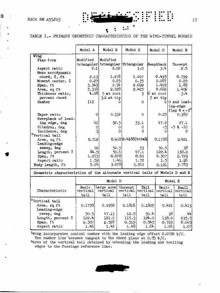
The models were all constructed so that the various component parts could be removed or modified. Two models were used in performing the tests of Model E. These models were essentially identical but one of the models incorporated certain modifications to allow for internal air flow. In the man, these modifications consisted of removing the side-inlet fairings, adding a duct exit fairing through which air egressed to the free stream, and extending and altering slightly the rear fuselage lines so as to accommodate both the duct exit fairing and the sting. Also the wing leading-edge flaps were deflected down 3' for a concurrent investi- gation of certain longitudinal characteristics of this ducted model. The primary geometric characteristics of the models are presented in table I.
TESTS AND PROCEDURE
The range of test conditions for the five models varies somewhat since this report is a compilation of five separate tests. Data were obtained for Mach numbers of 0.9 and for a supersonic range of about 1.2 to 1.9. The lowest supersonic test Mach number for a particular model was somewhat higher for the larger models in order that the shock waves reflected from the tunnel walls would not intersect any part of the model. The range df test variables for each model also differed somewhat. Data were obtained over a range of sideslip angles of about plus and minus 5' in increments of 2'. In some tests the plus range was extended to 8'. mary variable, the angle of attack was held constant; generally at 0' or 5'. The Reynolds number was held constant for each model with values ranging from 1 to 4 million for the various models.
For those tests with angle of sideslip as the pri- V'
Tests were made for several of the models with sidesli constant at 5' while the angle of attack was varied from -4 18' in increments of 2 O .
CJP, Cc/P, and C,/p between the results obtained at sideslip angles of plus and minus 3 . These values may disagree somewhat with the derivatives taken through zero angle of sideslip due to nonlinearities in the curves. usefulness of these figures is then to show the variation with angle of attack of the lateral-directional stability derivatives.
angle held to about 8
The lateral-directional stability parameters were obtained from these data by taking increments
0
The primary
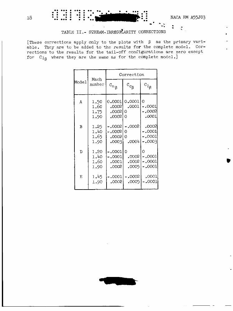
Corrections to the data to account for the effects of stream irregu-
The correction larities known to exist in the wind tunnel (ref. 1) were obtained by testing each model in the upright and inverted attitudes. was taken as one half of the difference between the slope of the upright and the inverted data (taken at stream irregularities were obtained from an analysis of the test results, it was not practical to include them in the ComDutation of the basic data
p = Oo and a = 0' ) . Since the effec>s of
b'
5
which is presented herein as plots with angle of sideslip or attack as the primary variable. atives have been corrected for the effects of stream irregularities in those figures where Mach number is the primary variable. derivatives were obtained by taking the slopes of the basic plots (which are uncorrected) and applying the corrections for stream effects from table 11.
However, the lateral-directional stability deriv-
The stability
A flow-visualization technique known as the "vapor-screen method" was used in tests of Model D to qualitatively study the flow field in the vicinity of the tail. is given in reference 2. In the present investigation the camera, used to photograph the vapor screen, was mounted directly behind the model in a manner similar to the rear camera in reference 2.
A rather complete description of the technique
RESULTS
The lateral-directional stability characteristics of the various versus Mach number.
However, as previ-
models are presented in plots of The basic plots of Cn, CC, and C2 versus p are also presented, pri- marily to show the nonlinearity with sideslip angle. ously noted, the basic data plots have not been corrected for the effects of stream irregularities and should be used with consideration of the corrections listed in table 11.
CnP, Ccp, and C1
The results of these tests are grouped according to models. No comparison of the test results for the various models is made. In order to facilitate identification of the model configuration for which the data in a particular graph pertain, a silhouette of the basic model con- figuration is shown in the upper portion of each graph. or additions to the model are shown as a dashed line on the silhouette. The form of presentation for each model group is as follows:
Any modifications
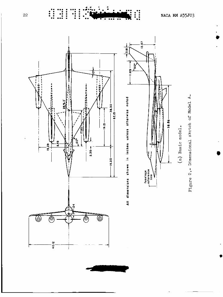
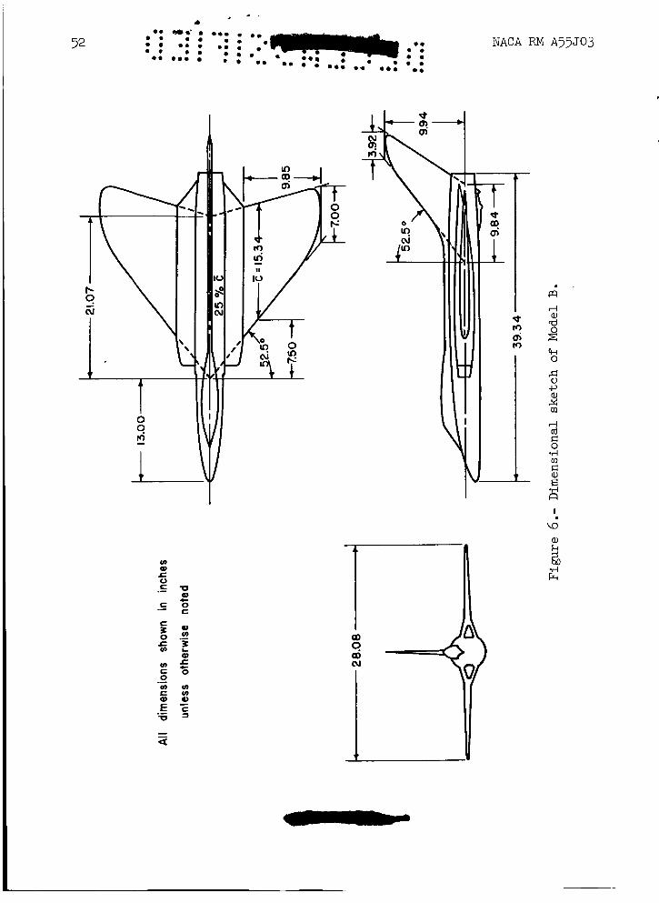
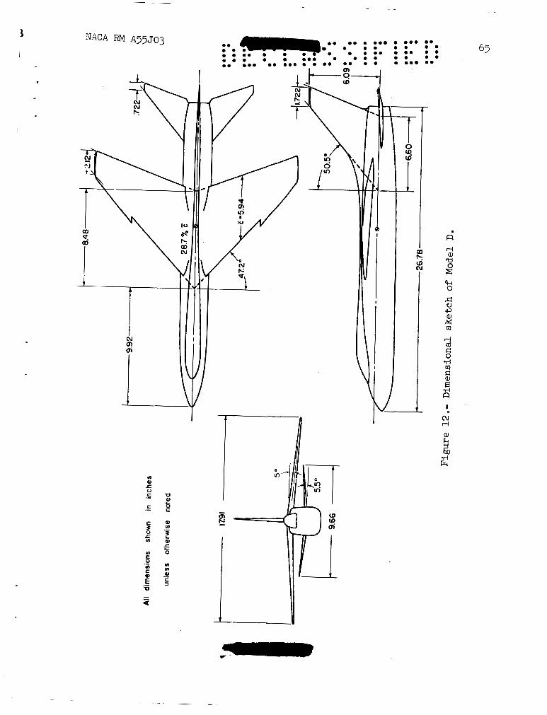
1. Dimensional sketch of the model.
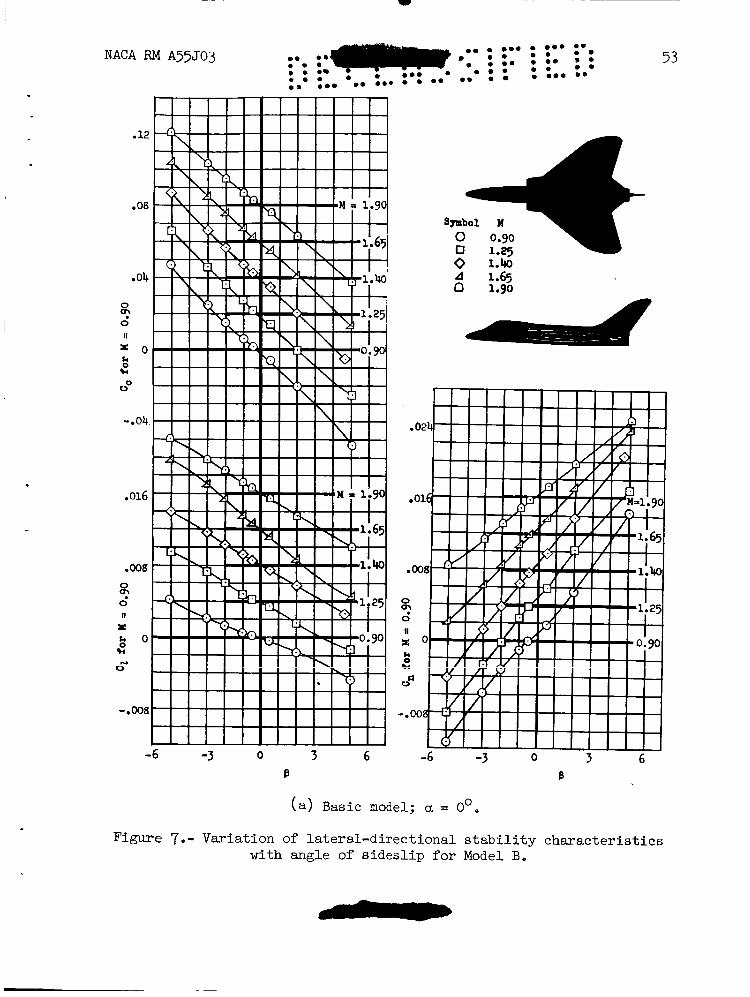
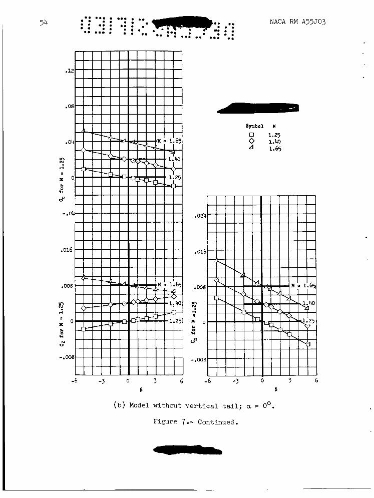
2. Variation of yawing-moment, rolling-moment, and cross-wind-force coefficient with angle of sideslip.
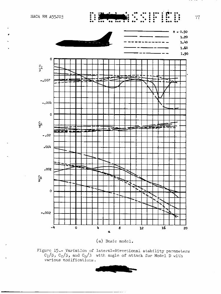
3. Variation of the lateral-directional stability parameters Cn/p, Cc/p, and C,/p with angle of attack.
4. Variation of the lateral-directional stability derivatives with Mach number.
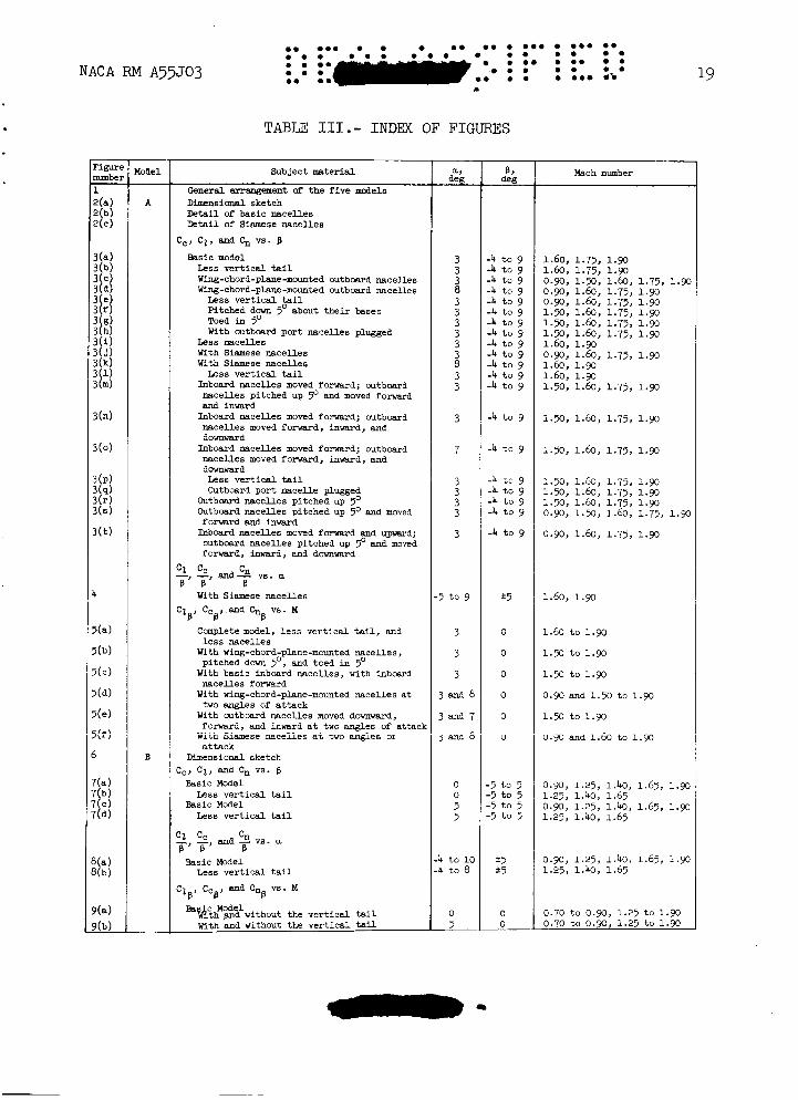
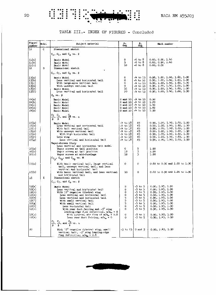
An index of the results is presented in table 111. order of presentation is adhered to throughout this report.
In general, this However, in
6
certain of the tests (Models C and E) the range of variables was insuffi- cient to warrant the complete presentation used for the other models. c
c
DISCUSSION
It is the intent to discuss herein only the broad aspects of the lateral-directional characteristics of each particular model and to point out the pertinent aerodynamic factors contributing to the results. Possi- ble conclusions to be drawn from a comparison of the aerodynamic qualities of the models are left to the reader.
Model A
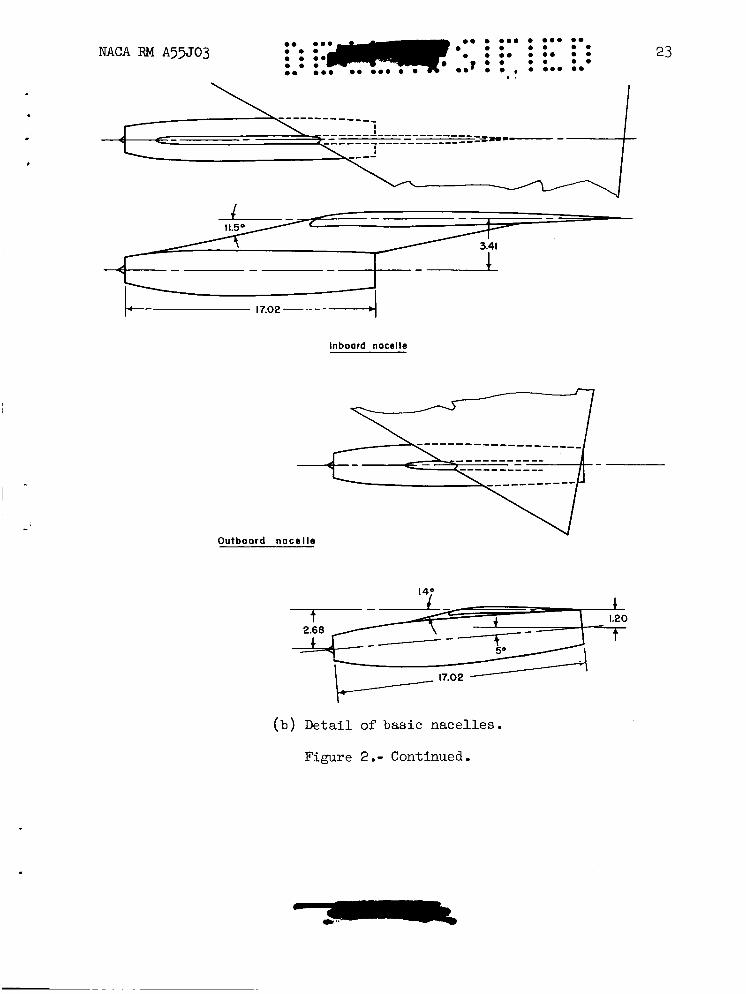
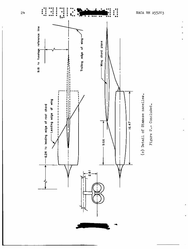
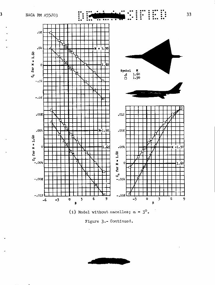
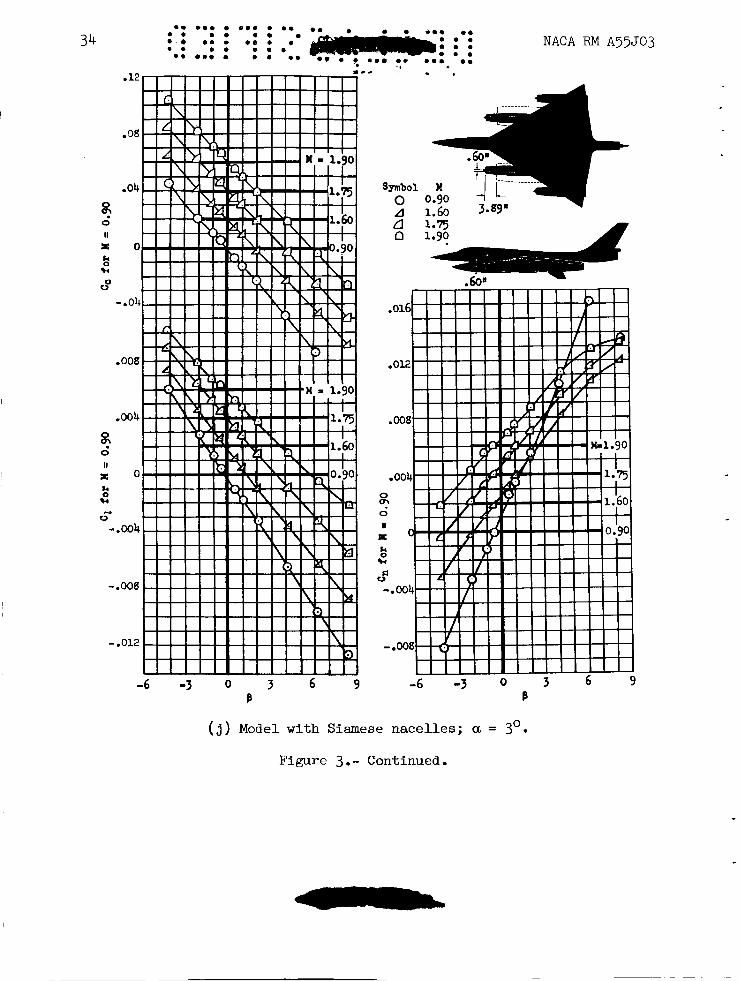
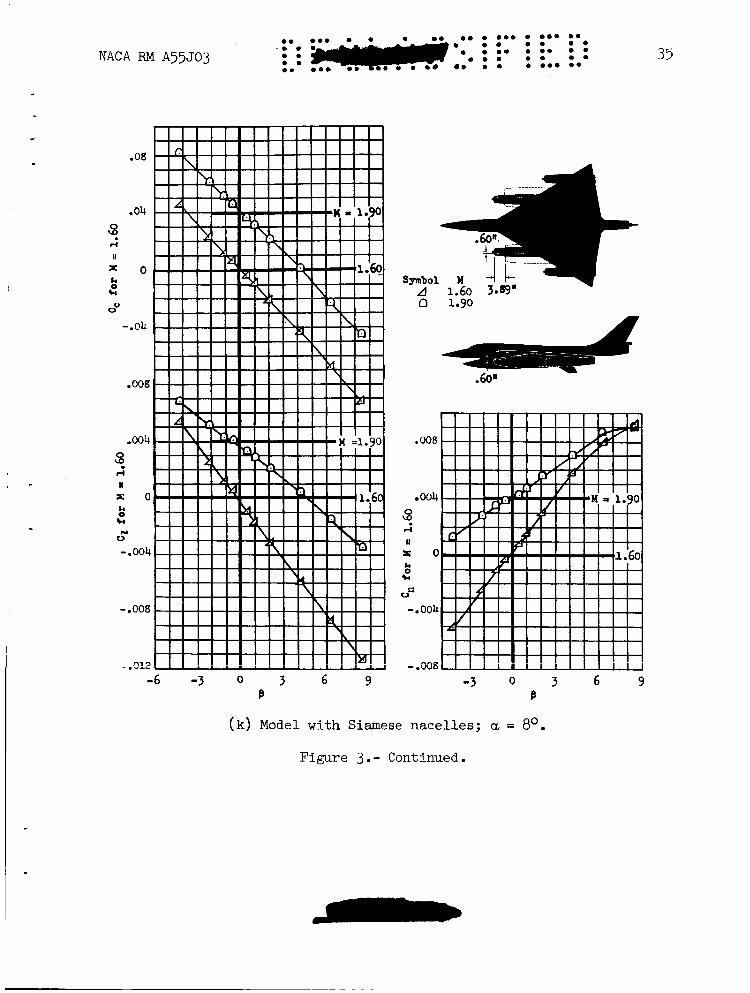
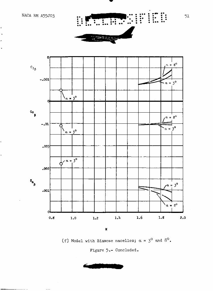
At supersonic speeds , externally mounted nacelles (or stores) can have large aerodynamic effects, particularly upon directional stability. This fact is significantly illustrated in the data for Model A, the geomet- rlc characteristics of which are shown in figure 2. Detailed information concerning the effects of nacelle position upon the lateral-directional characteristics of this model for both tail-on and tail-off configurations is presented in figure 3. The variation of Cl//3, CC/p, and Cn/p with angle of attack is shown in figure 4 for the model with Siamese nacelles. Portions of the data presented in figure 3 are more conveniently summarized in figure 5.
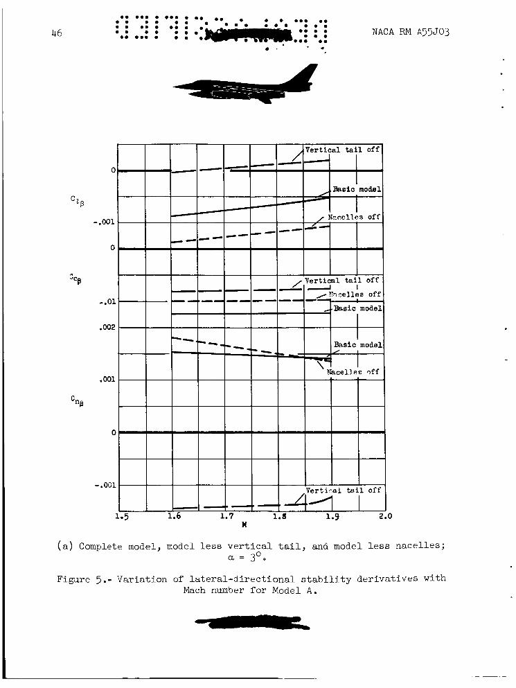
Interference effects of the nacelles on the vertical-tail effective- ness can be seen best by comparing the directional stability of the model with the nacelles off (dashed line in fig. 5(a)) and with the outboard nacelles mounted in the wing chord plane (solid line in fig. 5(b)). the lowest supersonic Mach number where comparable data exist (Mach number of 1.6), the model with chord-plane-mounted nacelles shows a substantial decrease in directional stability relative to that of the model without nacelles. The difference between the directional stability for the two configurations diminishes with increasing Mach number to the extent that at a Mach number of 1.9, essentially no effect of the nacelles upon this parameter is evident. The decreased directional stability for the model with outboard nacelles mounted in the wing chord plane is evidently caused by the compression waves from these nacelles which impinge upon the verti- cal tail. The effect of these waves is to decrease the loading on the vertical tail due to sideslip and consequently to decrease the directional stability. To illustrate how the outboard nacelles influence the direc- tional stability, consider the case of a positive sideslip angle (right wing advanced). surface while the inboard side of the left nacelle becomes a corresponding compression surface. When the expansion waves from the right nacelle and
At
The inboard side of the right nacelle becomes an expansion
-
the compression waves from on the vertical tail,
. .
mo m m 0 0 0 0 0.0 om 0 0 m o 0 0
0 0 0 mo e m m m o m
m m m 0 0
0 0 moo 0 0 m o o o m 0
om om0 NACA RM ~ 5 5 ~ 0 3 . 0 ' 0 .. 0 7
the differential loading results in a destabilizing force on the vertical tail. It can be seen that the nacelle-vertical-tail interference depends on the relative location of the nacelle Mach cones and the vertical tail. This interference, for a given outboard nacelle location, is then a func- tion of Mach number, angle of sideslip, and angle of attack. At higher supersonic speeds, the pressure disturbances from these nacelles which are propagated nearly along Mach lines *mabe rearward. The boundary of the area of the vertical tail inf&u(?n&d by these pressures, therefore, moves rearward and the extent ef*this region diminishes with increasing Mach number. pass behind the vertical tail. However, the tail moves into the distur- bance region with increasing sideslip angle resulting, as shown in figure 3( c), in decreased directional stability at sideslip angles larger than 4' at a Mach number of 1.75 and larger than 6' at a Mach number of 1.9.
At a Mach number of 1.9 the pressure disturbances apparently
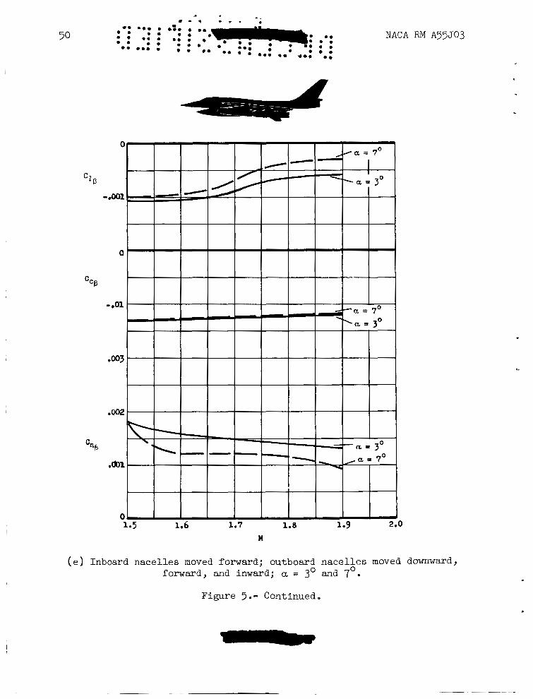
The results show a general decrease in directional stability with increasing angle of attack for this model with several nacelle arrange- ments (figs. 5(d) through 5(f)). is believed to be the result of a l o s s in the effectiveness of the verti- cal tail which, at supersonic speed, occurs primarily because of the decreased dynamic pressure associated with the expansion of the air stream over the upper surface of the wing at positive angles of attack. The for- ward position of the vertical tail relative to the wing contributes to its vulnerability from this source, particularly at the higher Mach numbers.
The reduction in directional stability
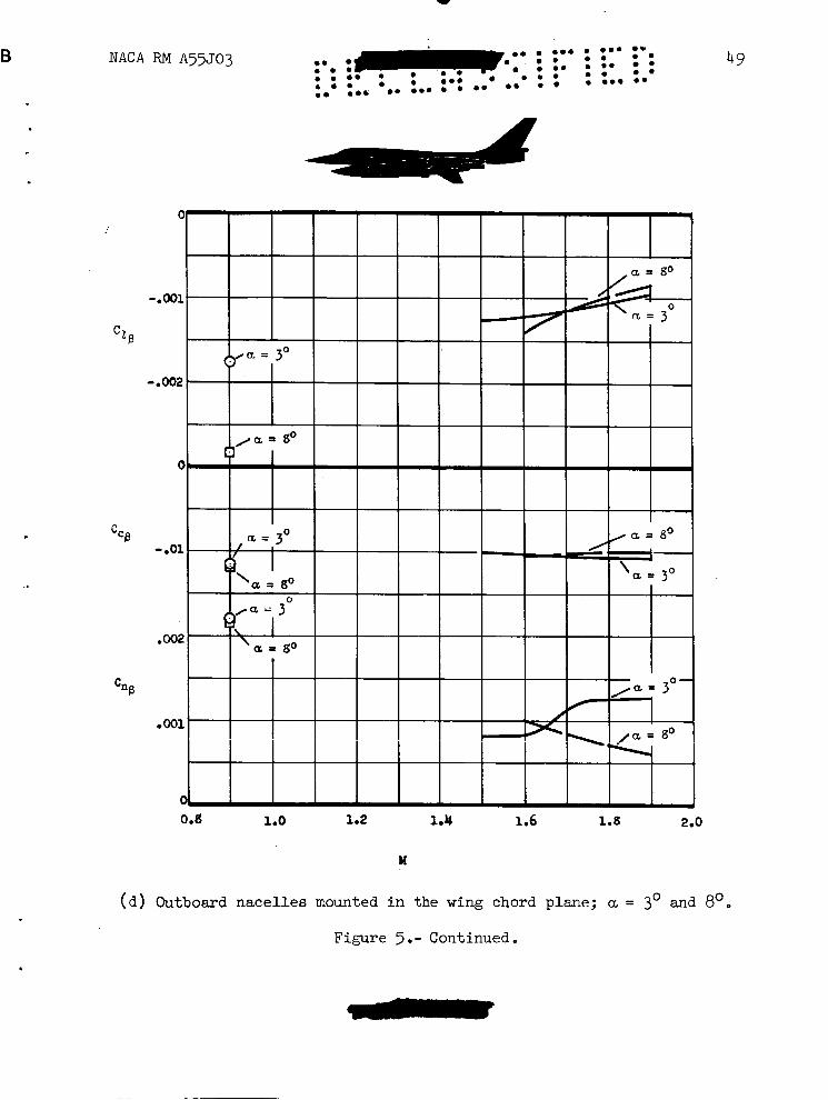
Another effect of angle of attack on directional stability is shown for the model with chord-plane-mounted outboard nacelles (fig. 5( d) ) . Results in the figure show not only a decrease in stability at an angle of attack of 8' compared to an angle of attack of 3 O , but also a considera- bly different variation with Mach number. Since the relative position of the vertical tail with respect to the Mach cones from the nacelles chan es with angle of attack, it is conceivable that at an angle of attack of 8 the interference effects previously discussed might occur at a higher Mach number and that the strength of these effects might be changed.
8
Not all the nacelle arrangements tested decreased the directional stability. Specifically, when the model was fitted with outboard nacelles mounted under the wing, adverse interference effects were not evident. In these cases the vertical tail was shielded from the outboard nacelles by the wing.
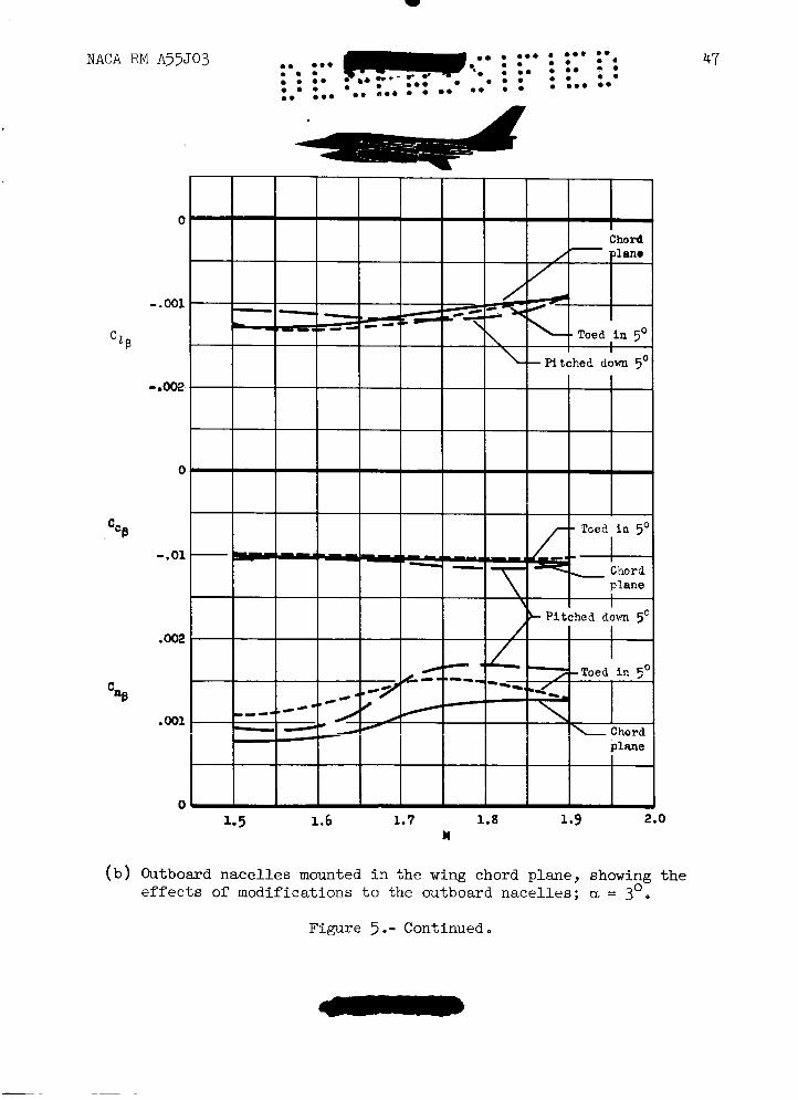
Two modifications were made to the chord-plane-mounted nacelles to improve the directional stability of the model. The outboard nacelles were pitched down 5' from their original position to lower the inlets, and the nacelles were rotated inboard (again from the original position) to bring their inlets closer to the vertical plane of symmetry. results of these nacelle modifications on the directional stability (fig. 5(b)) indicate that small changes in shielding of the vertical tail or in location of the nacelle Mach cones relative to the vertical tail
The
a
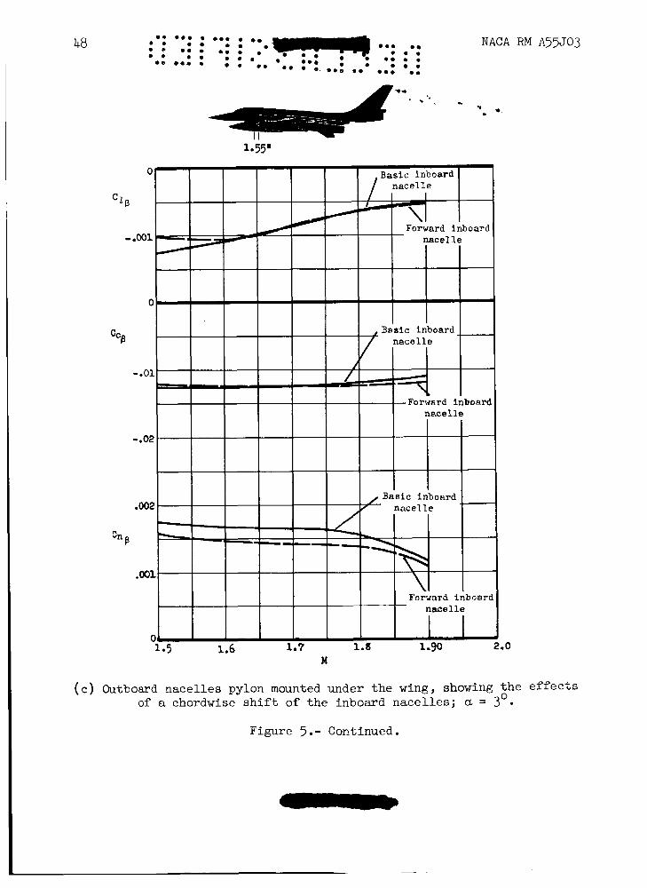
can reduce the interference effects considerably. Part of the increased stability for the model with "toed-in" nacelles is due to direct air loads on the nacelles as the asymmetric nacelle drag in sideslip is stabilizing. It might be noted that a chordwise shift of the inboard nacelle has no unusual effect on the lateral-directional stability characteristics of the model (fig. ?(e)).
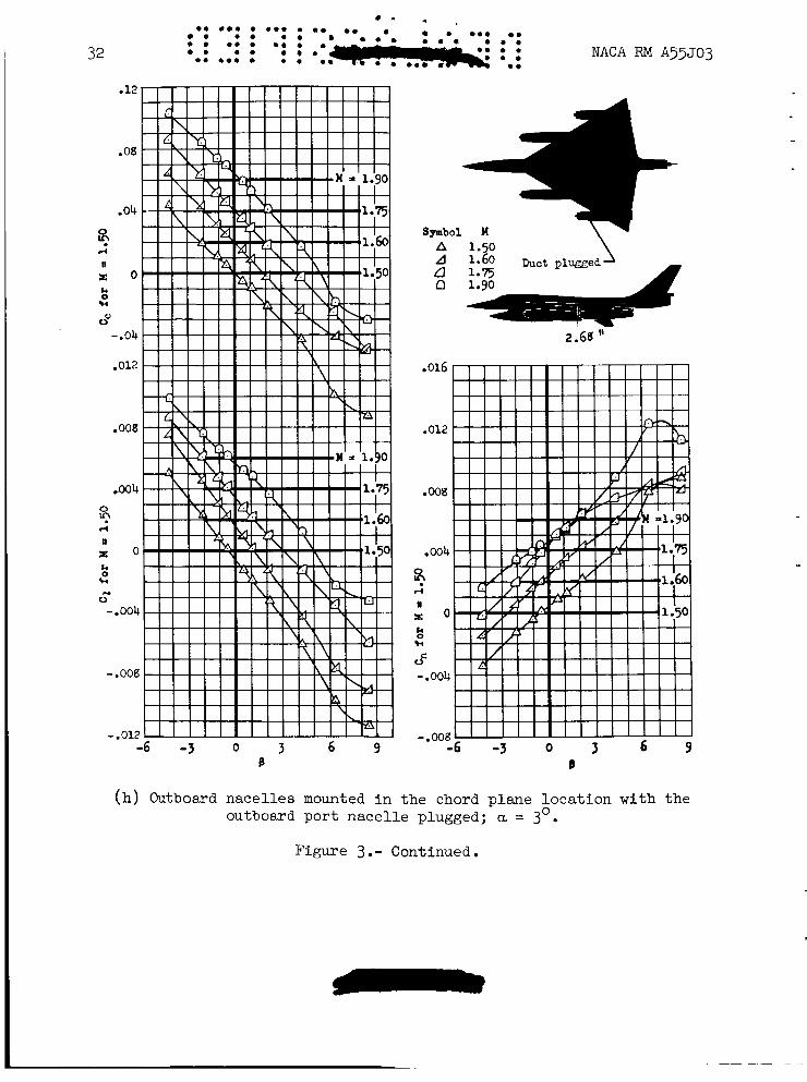
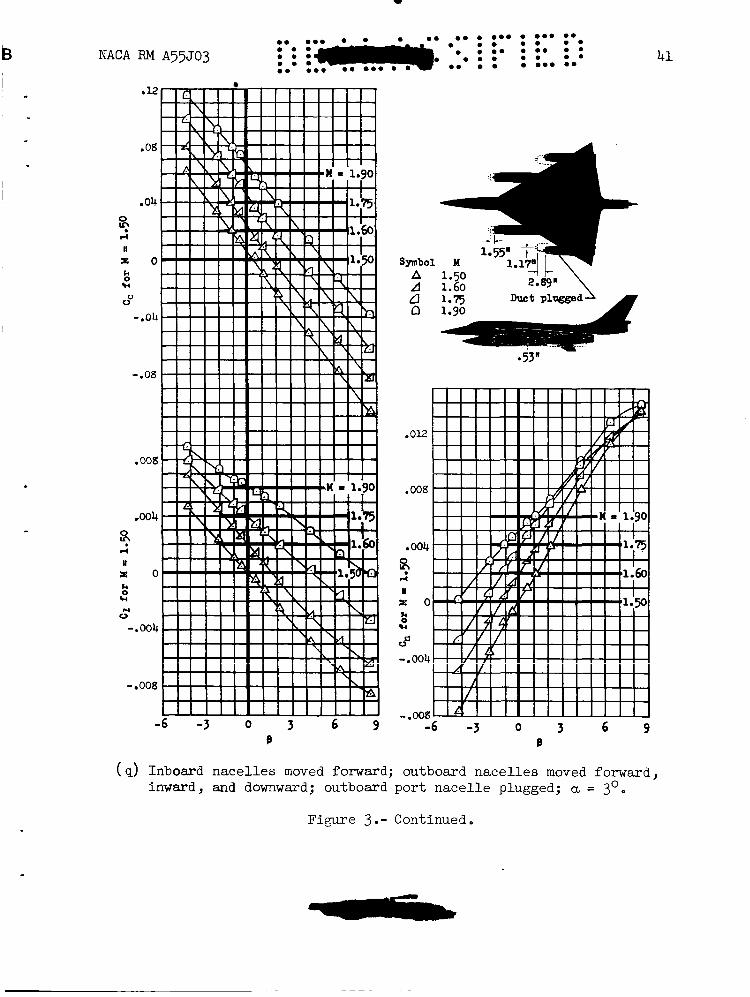
The consequence of a sudden engiAe failure for an airplane with external engine nacelles mounted well outboard of the plane of symmetry is of considerable concern. In this investigation the static-lateral- directional stability characteristics were obtained for the model with an outboard nacelle plugged to simulate this condition. only the aerodynamic effects of reducing the duct mass-flow ratio to zero and no attempt was made to simulate asymmetric thrust conditions. nacelle arrangements were tested in this condition. Figure 3(h) presents results for a plugged chord-plane-mounted nacelle while figure 3(q) is a plugged pylon-mounted nacelle. The same nacelle arrangements, unplugged, are shown in figures 3( c) and 3(n). port outboard nacelle plugged exhibited a small increment of negative yawing moment, compared to the symmetrical condition, which increased with speed to an unbalanced equivalent to a 2 O yaw angle at a Mach number of 1.9 for the chord-plane-mounted nacelles. of the model with a chord-plane-mounted outboard nacelle plugged was decreased slightly while the pylon-mounted outboard nacelles showed little change except at a Mach number of 1.90 where both arrangements show a siz- able decrease in directional stability. The erratic variation of the lateral-directional characteristics with sideslip angle for the model with a chord-plane-mounted nacelle plugged ( fig . 3( h) ) is probably the result of the nacelle-tail interference previously discussed (note that these variations did not occur for the model with pylon-mounted nacelles). It is difficult to analyze the effects of nacelle-tail interference for one outboard nacelle plugged since the Mach cones from the nacelles are no longer symmetrical and the position of the detached bow wave in the vicinity of the vertical tail cannot be predicted.
These data show
Two
Both nacelle arrangements with the
The directional stability
The conical camber in the wing of Model A was incorporated for reasons other than those pertaining to the lateral-directional stability char- acteristics. Tests were not made to evaluate the extent to which this camber influenced the present results, although it is believed to have but a small effect. Conical camber and its influence on the lateral- directional stability characteristics of a wing similar to that of Model A is discussed in reference 3.
NACA RM A57J03 9
Model B .
The three-view drawing of this model (fig. 6) shows the wing plan . form to be basically triangular, but modified by rounded tips and indented trailing edges. The model had a sweptback vertical tail but no horizontal tail. Side inlets were incorporated in the fuselage. These engine inlets blended into the wing root as a fillet-type fairing. internal ducts and exhausted at the rear of the fuselage at mass-flow ratios that were representative of flight conditions.
Air flowed through
The lateral-directional stability characteristics versus sideslip
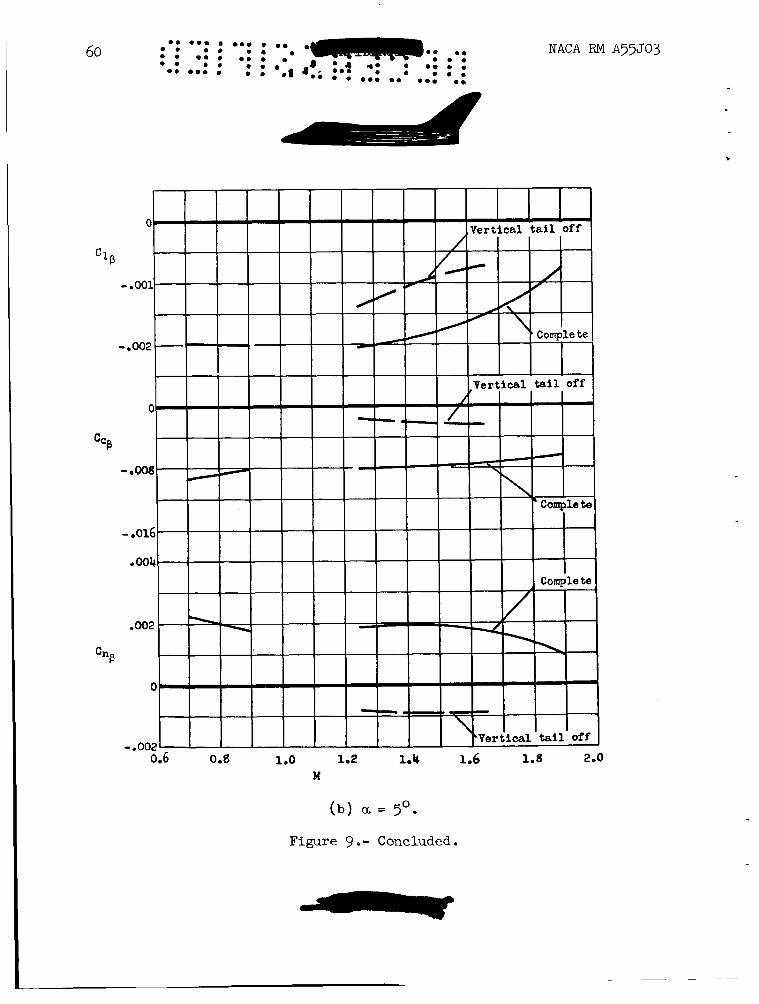
The decrease in directional sta- angle of Model B (presented in fig. 7) showed no anomalous variations with angle of attack or Mach number. bility with increasing angle of attack (fig. 8) is believed to be due primarily to a decrease in tail effectiveness resulting from the decrease in dynamic pressure associated with the expansion of the air stream pass- ing over the upper surface of the wing at angle of attack. The decrease in directional stability with Mach number (fig. 9) is no greater than would be expected, from consideration of compressibility effects.
The variation of rolling-moment coefficient with angle of attack and Mach number shown by this model (fig. 8) is an intrinsic property of the wing plan form. The variation of the parameter C,/p with angle of attack is negative and reduces in magnitude as the Mach number increases to M = 1.65. The slope of the C,/P curve is positive for a Mach number of 1.90 where the component of velocity perpendicular to the wing leading edge is supersonic. These results, including the reversal of sign when the wing leading edge becomes supersonic, are in good agreement with pre- dictions based on linearized potential theory (ref. 4) for a triangular wing of aspect ratio 2.
Model C
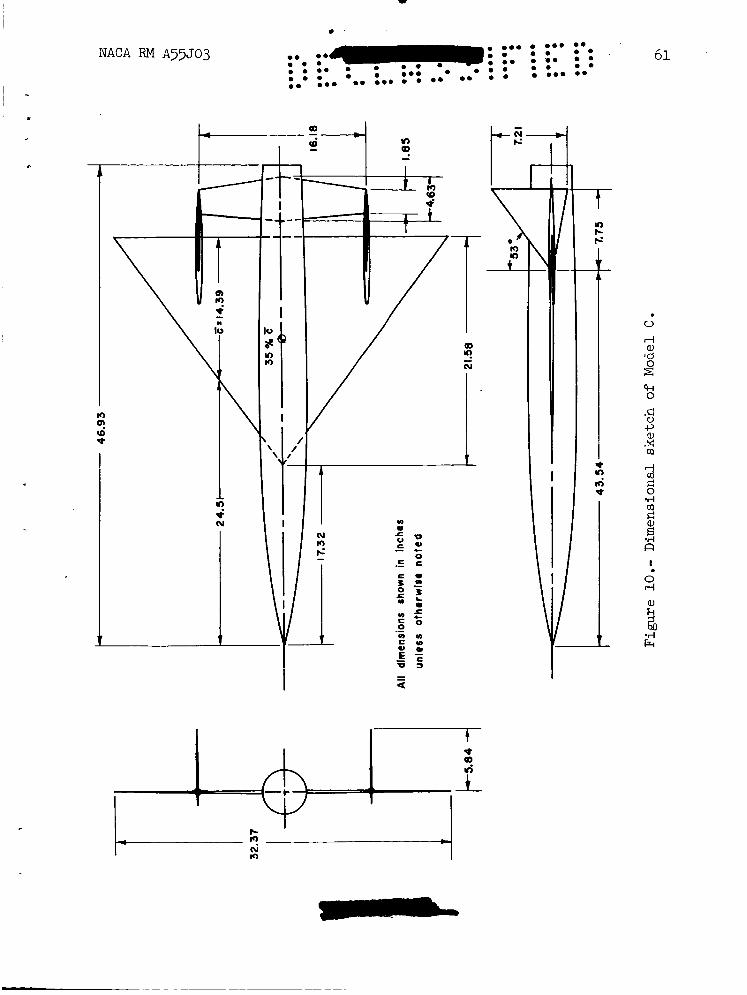
The aerodynamic results for Model C illustrate the lateral-directional stability characteristics of a triangular-wing airplane similar to Models A and B, but stabilized by twin vertical fins mounted midway out on the wing (see fig. 10). detached from the wing trailing edge, which was believed to have only a secondary effect on the directional characteristics. The wind-tunnel investigation from which these data were obtained was concerned primarily with the longitudinal characteristics of the model; however, a limited amount of lateral data was obtained. These data are considered to be important since they point out the existence of severe lateral-directional stability reversals which might occur for any airplane, during certain flight conditions, with a highly swept wing leading edge and with vertical fins mounted outboard on the wing.
This model also had a longitudinal control surface,
10 NACA RM A55J03
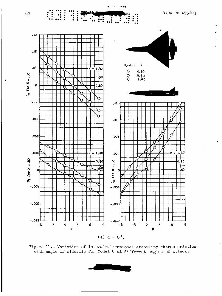
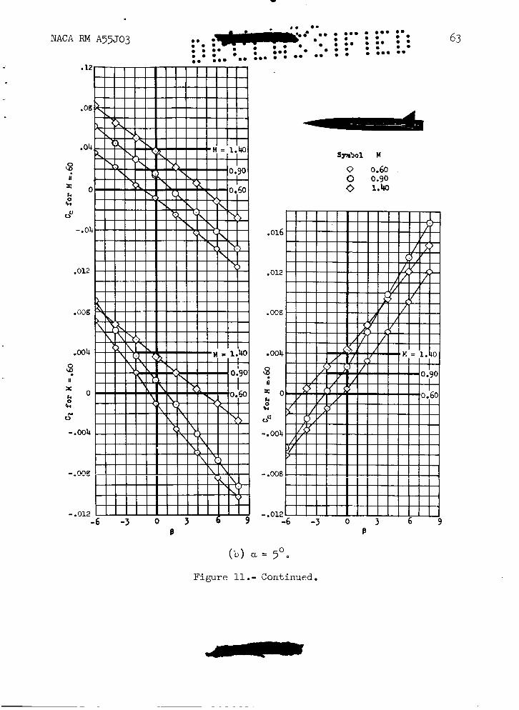
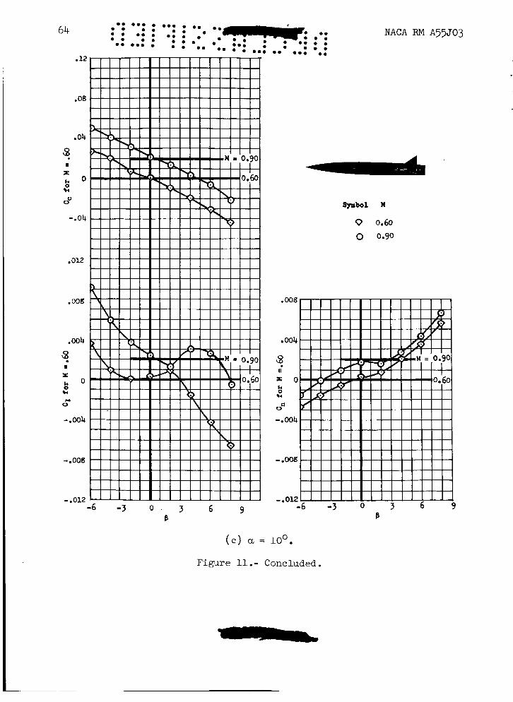
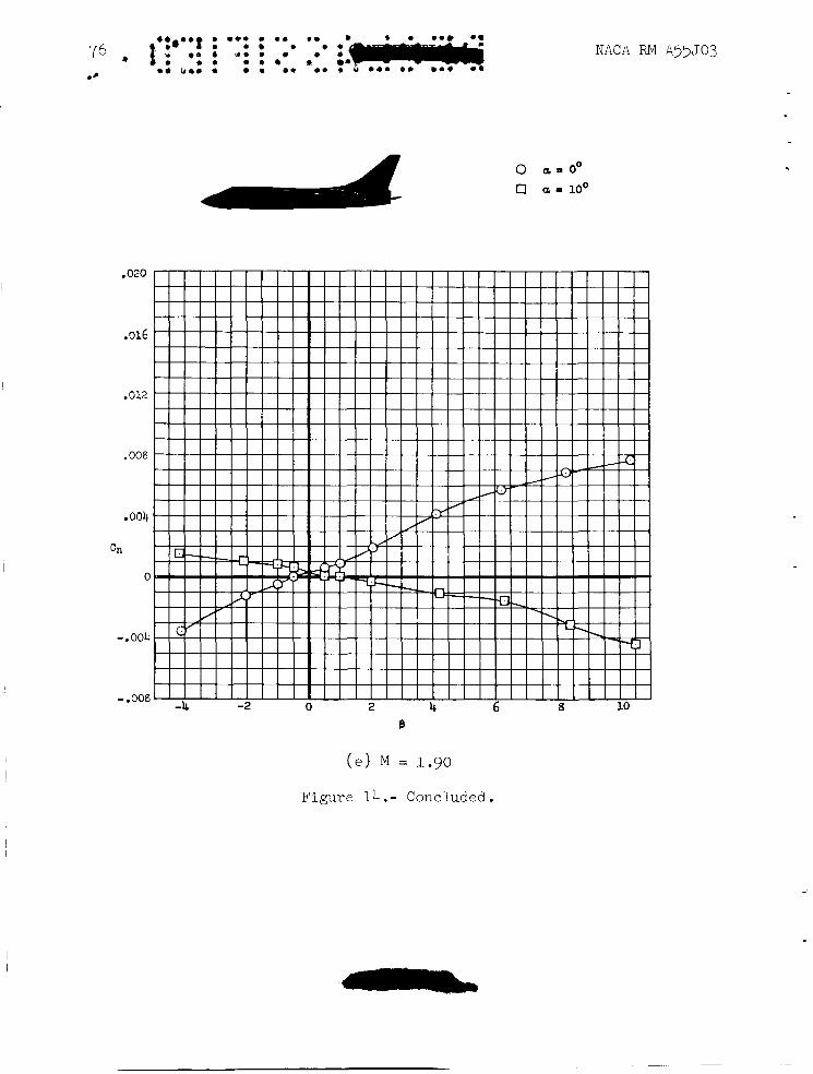
Figure 11 presents the Iate~=directional stability characteristics of Model C at angles of attack of Oo, 5', and 10'. slightly nonlinear at 0' and 5' (figs. ll(a) and ll(b)); however, at 10' angle of attack (fig . 11( c) ) the yawing-moment and rolling-moment charac- teristics for the two subsonic Mach numbers show reversals at small angles of sideslip. characteristics of the model (not presented in this report) which also revealed discontinuities in the 10' angle-of -attack region. The lift- curve slope decreased slightly and there was a forward shift in the center-of-pressure location which would indicate the onset of a wing- tip stall. Similar variations in the longitudinal characteristics were observed in reference 5 with regard to an aspect-ratio-2 triangular wing even though no fins were.mounted on the wing. noted that these variations result from the failure of the separated flow at the leading edge of the wing to reattach over the outboard portion of the wing at the higher angles of attack. It is apparent then that in the neighborhood of loo angle of attack the wing of Model C is in a critical region of tip stall. Further, it is believed that the presence of the vertical fins near the critical region of detached flow has an adverse effect on the flow pattern over the wing and that, when separation occurs, the entire portion of the wing outboard of the fins stalls. It is con- jectured that when the model was yawed at an angle of attack of loo, the change of the air-flow pattern over the wing resulting from the decrease in effective sweep angle caused a premature stall on the advancing wing. The sudden stalling of the advancing wing tip produces the reversal of dihedral effect found near zero sideslip angle. The decrease in direc- tional stability which accompanies the rolling-moment variations is due to mutual interference between the wing tips and fins. The tip stall on the advancing wing apparently decreases the effectiveness of the adjacent fin. These observations are substantiated by the results of an investi- gation (ref. 6) of the effects of outboard fins on the static-stability and rolling characteristics of a triangular wing model. The results pre- sented in figure 11( c) are somewhat erratic (rolling-moment and yawing- moment curves lack symmetry) because of the difficulty in obtaining con- sistent data for the unsteady flow conditions associated with the wing- tip stall.
The data are only C
An examination was made of the longitudinal aerodynamic
In reference 5, it was
Model D
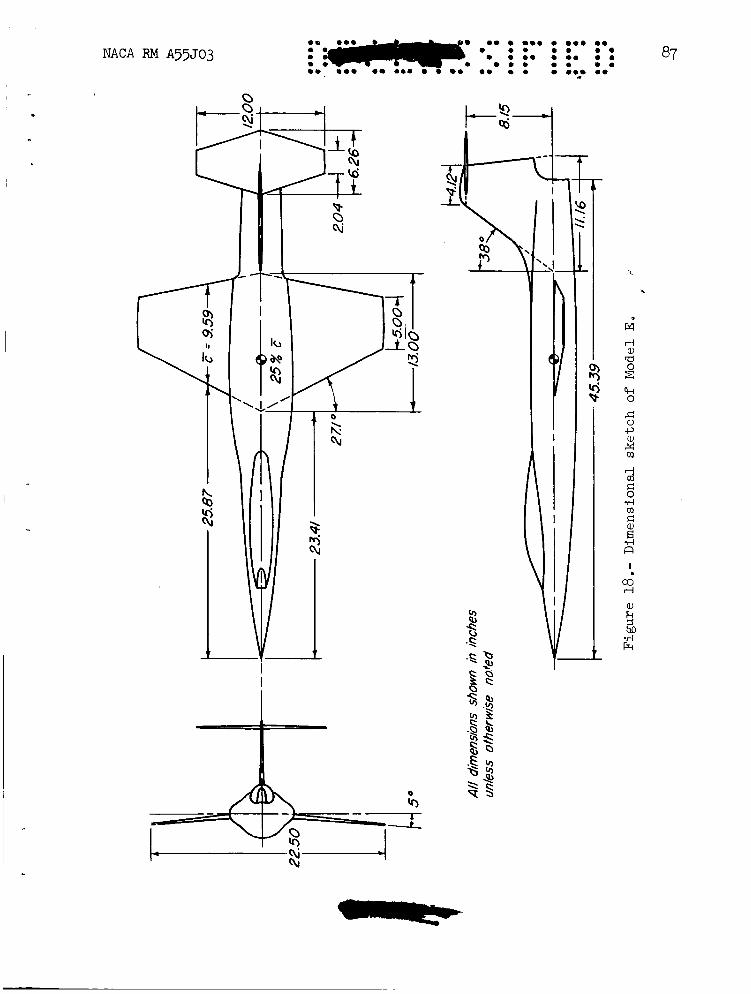
The lateral-directional characteristics of this model are interest- ing, particularly in that the results offer the opportunity to study the aerodynamic influence of the fuselage upon the stabilizing effectiveness of the tail. A three-view drawing of this model is shown in figure 12 and further details concerning its geometric characteristics are presented in table I.
NACA RM A55503 11
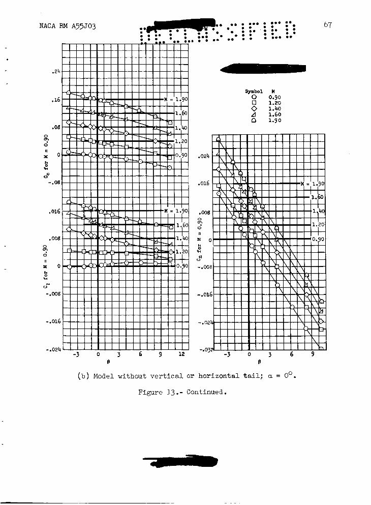
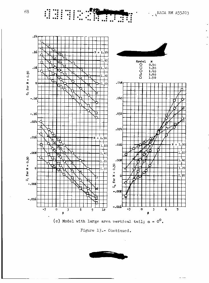
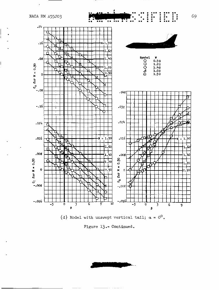
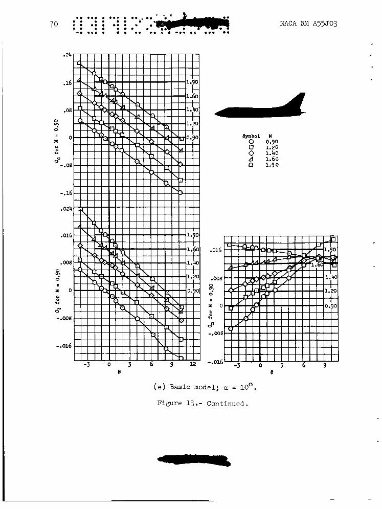
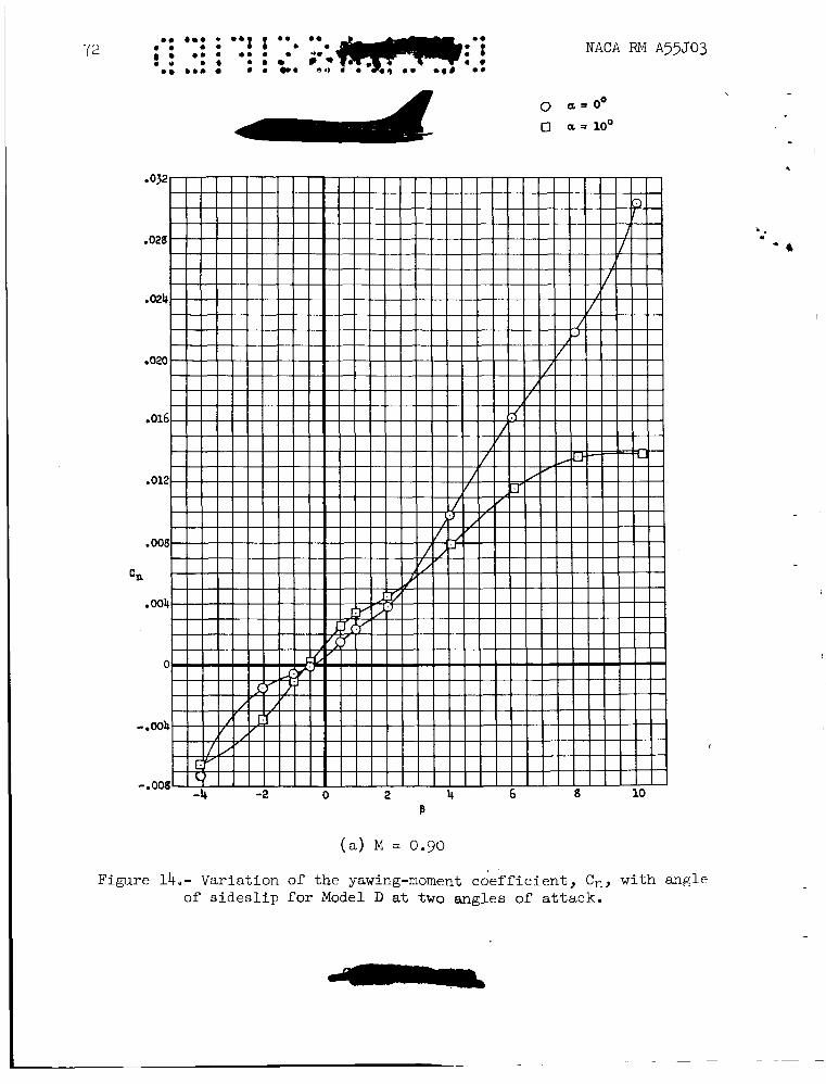
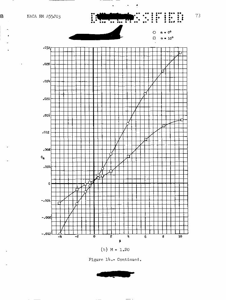
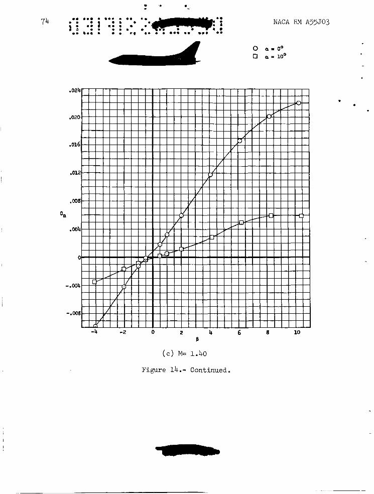
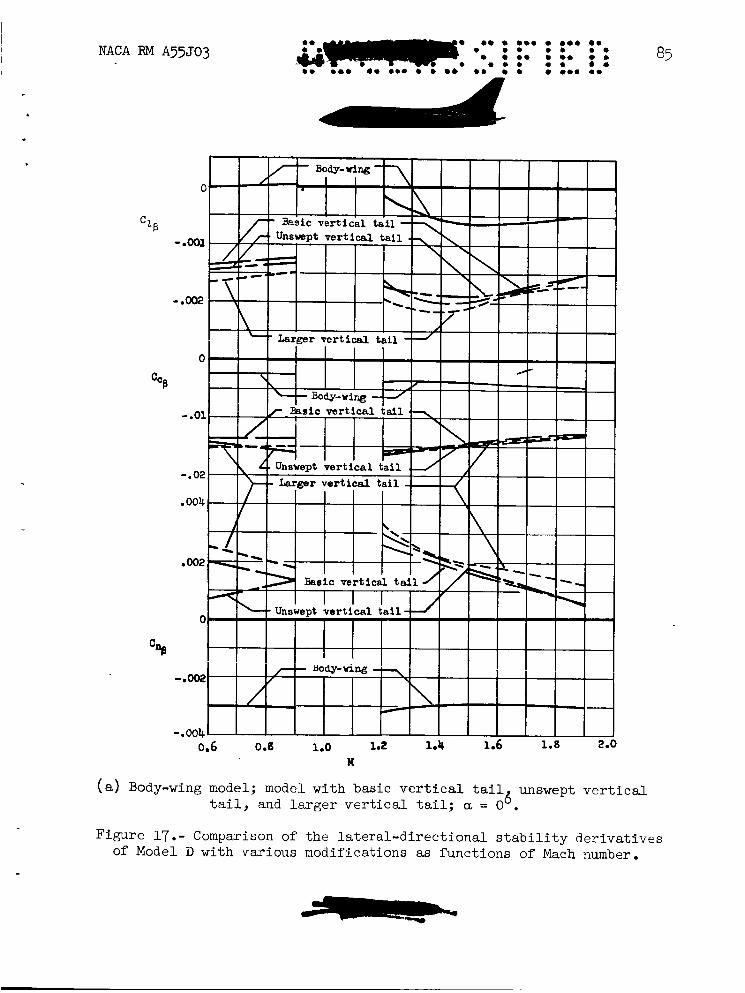
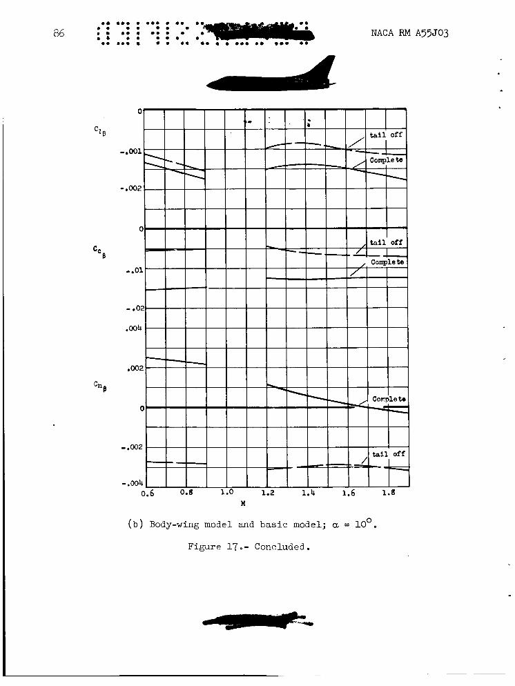
The coefficients CC, C2, and Cn vs. B are presented in figure 13 while figure 14 shows Cn vs. B , on a larger scale, for the basic model at angles of attack of 0' and 10'. Figure 15 presents the variation of Cl/j3, Cc/B, and Cn/p with a, for the basic model with various modifi- cations. Photographs showing the flow pattern behind the wing-body model are shown in figure 16. Figure 17 presents the variation of the lateral- directional stability characteristics with Mach number at angles of attack of Oo and 10' for the model with several vertical-tail arrangements. From an examination of the data presented in figures 15 and 17, it is evident that the directional stability of Model D decreased markedly with increas- ing angle of attack and Mach number, especially at supersonic speeds. Moreover, the yawing moment of the model (fig. 13) varies nonlinearly with sideslip angle because of the nonlinear variation of vertical-tail load with sideslip (cf. figs. l3(a) and l3(b)). A more detailed exami- nation of this nonlinearity is presented in figure 14, wherein the variation of the yawing moment with sideslip angle is shown at two angles of attack and several Mach numbers.
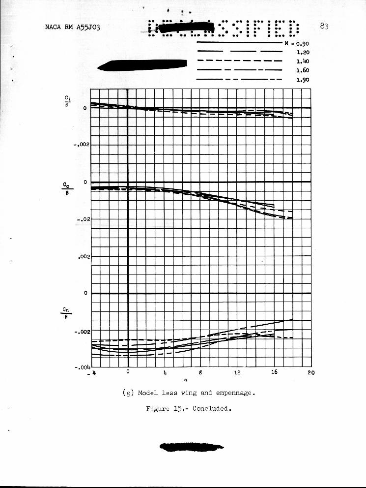
The decrease in directional stability with Mach number shown in figure 17 is about as expected, from consideration of the effect of Mach number upon the vertical-tail effectiveness. Notice, however, that the large destabilizing body contribution remains constant with Mach number while that of the vertical fin decreases so that the model has almost neutral directional stability at a Mach number of 1.9. addition of the wing has very little effect upon this unstable body con- tribution can be seen by comparing the results for the body alone w'ith those of the wing-body combination (see figs. l5(g) and l?(b)).
That
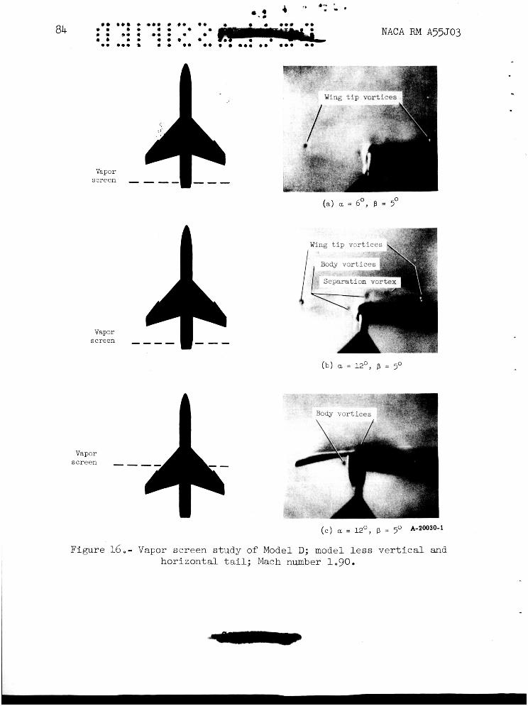
Investigation of the effect of angle of attack upon the lateral- directional characteristics revealed a further serious effect of the long fuselage. The deterioration of directional stability with increasing angle of attack (fig. 15) was found to be related in part to the fact that the effectiveness of the vertical taiL is influenced by vorticity associated with the lifting fuselage. A qualitative study of this problem was made by examining tne induced ?low rield i r i t h e t a l i regloii of Model D in conditions of combined angle of attack and sideslip with the vapor-screen flow-visualization technique described'in detail in reference 2. Some typical vapor-screen photographs obtained in these tests are shown in figure 16. The point from which these photographs were taken was located inside the wind tunnel directly downstream from the model. The thin plane of intense light was projecting across the wind tunnel from the left; consequently, a shadow of the model was cast to the right. regions of concentrated vorticity shed from lifting elements of the model forward of the vapor screen. moisture particles outward from their centers of rotation. areas of the vortices, therefore, are devoid of particles capable of reflecting light and hence these vortex regions appear as dark spots on the vapor screen.
The dark circular spots on the vapor screen are caused by
The spinning action of the vortices forces Innermost
12 NACA RM A55J03
In figure 16(a) the dark spot at the left is caused by the wing-tip vortex shed from the left wing of the model. The corresponding vortex from the right wing is obscured somewhat by the shadow cast by the fuse- lage. In addition to these vortices, two more vortices originating from the fuselage are shown to be located in close proximity to the positions normally occupied by the tail of the model. Note that at 12' angle of attack the intensity of all of the vortices increases (see fig. 16(b)) as is indicated by an increase in the size of the dark spots. Also, at 12' angle of attack another vortex appears at a point approximately midway between the fuselage and the right wing-tip vortex. This vortex is believed to form as a result of flow separation associated with the leading edge of a sweptback wing. Because of the proximity of the fuse- lage vortices to the tail position, particularly the vertical tail, it is believed that they have a large effect upon the directional stability of the model at angle of attack. Similarly, the directional stability probably is influenced to a lesser degree (in the angle ranges tested) by the induced effects of the wing-tip and separation vortices because of their remote location relative to the tail. From physical considera- tions in conjunction with a study of the location and direction of rota- tion, particularly of the upper fuselage vortex, it is believed that the dorsal fairing and the lower portions of the vertical tail are in regions of adverse sidewash when the model is at combined angle-of-attack and -sideslip conditions.
Forward movement of the vapor screen to the midpoint of the body in figure 16(~) shows that at this position the center of rotation of one of the fuselage vortices is under the left wing and that of the other is above the fuselage. It is probable that the effect of Mach number in the supersonic range has little influence upon the induced flow patterns shown in figure 16 (ref 2 ) .
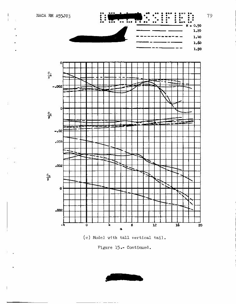
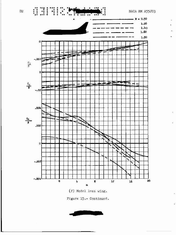
An estimate of the magnitude of the induced effect of the fuselage upon the vertical-tail effectiveness can be obtained by comparing direc- tional stability of the body alone in figure l5(g) with that of the body- tail combination (fig. l5( f)) . Note that at about 14' angle of attack the vertical tail has lost its effectiveness almost entirely, despite the fact that the area of the vertical tail is about 30 percent of the wing area. bination with that of the complete model, it is evident that some improve- ment in directional stabillty occurs as a result of the addition of the wing. This result probably is caused by the wing downwash restricting to some extent the vertical movement with angle of attack of the fuselage vortex which passes near the vertical tail and by a decrease in the strength of the fuselage vortices. Tests of the model with vertical tails of higher aspect ratio and with lesser sweepback angle, figures l5(c) and 15( d) , show only slight improvement in the directional characteristics, except at a Mach number of 1.9 where a small loss is shown. This decrease in directional stability occasioned by these vertical-tail modifications
By comparing the directional stability of the body-tail com-
is believed to be the result of a 1 of dynamic pressure when the
d b b
NACA RM A 5 5 J 0 3
vertical tail was extended upward or forward since the shock waves emanating from the trailing edge ofthe wing at a Mach number of 1.9 cross the vertical tail in the region of the tip.
13
A s noted in the "Procedure" section of this report, the lateral- directional data presented as functions of angle of attack have not been adjusted for the effects of air-stream irregularities. Hence, the level of the data may be slightly in error although the variation with angle of atta'ck is believed to be correct.
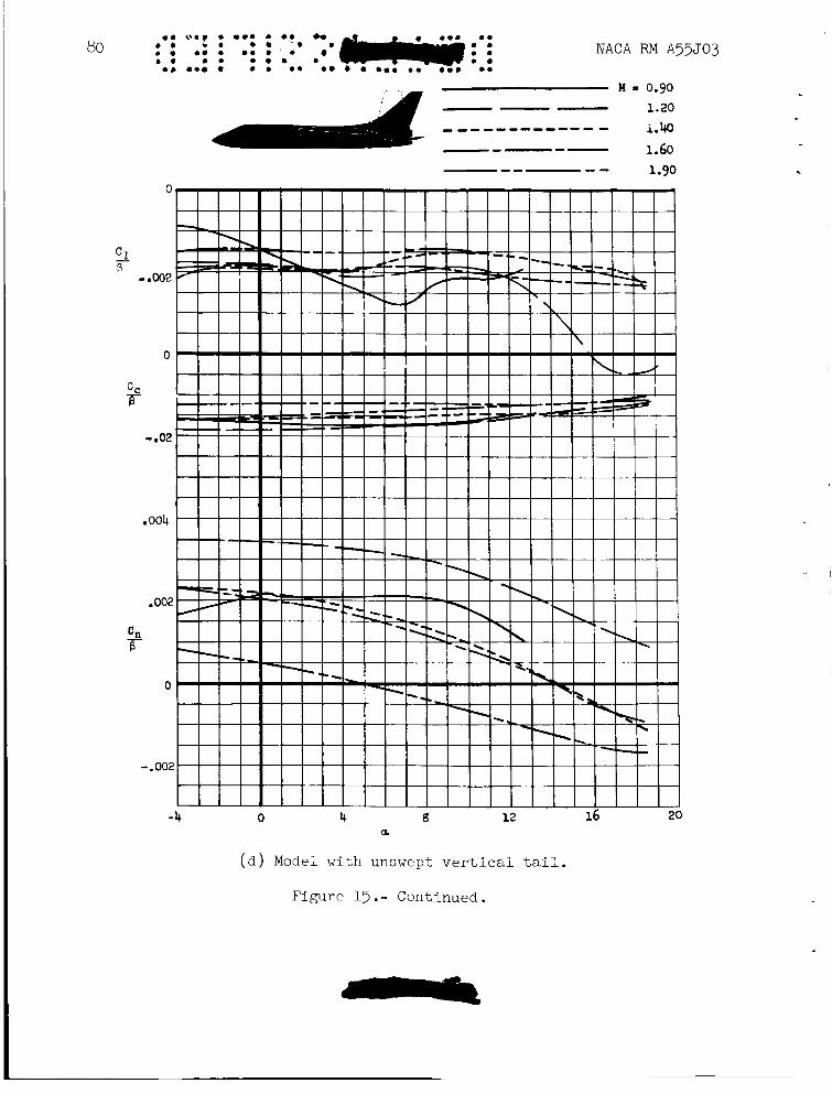
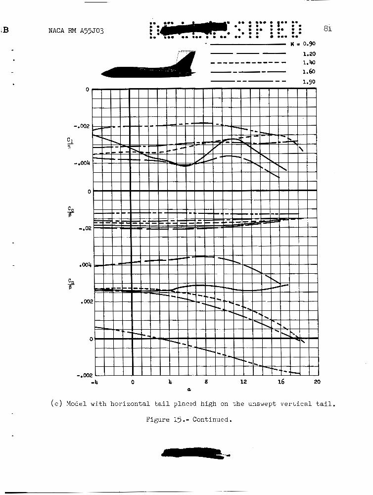
The influence of horizontal-tail and vertical-tail interference on the lateral-directional characteristics of Model D, especially at higher angles of attack, was cursorily investigated in tests with the horizontal tail mounted at the tip of the vertical tail. teristics of the model with an unswept vertical tail with the horizontal tail mounted low on the fuselage and on the tip of the vertical tail is shown in figures l5(d) and l5(e). The end-plate effect of the horizontal tail, when mounted at the tip of the vertical tail, is evident in these figures by the increased cross-wind-force and yawing-moment parameters at an angle of a.t.tack of 0'. A more significant effect of the high tail on the characteristics of this model is the improvement in the variation of directional stability with increasing angle of attack. This is the result of horizontal- and vertical-tail interference and so varies with horizontal-tail loads. Both the end-plate and interference effects of the high horizontal-tail position contribute a positive dihedral effect. the end-plate and interference effects of the horizontal tail exist only within the Mach cone of the horizontal tail, the gains in the directional characteristics of the model diminish with increasing Mach number.
A comparison of the charac-
Since
Model E
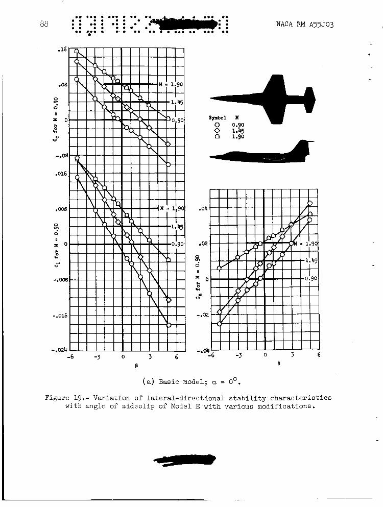
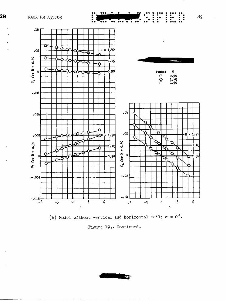
The effect of horizontal-tail position on the longitudinal charac- teristics of aircraft has received considerable attention. Results for Model E (see fig. 18 for dimensional.sketch) permits a study of the influence of a high horizontal-tail location on the lateral-directional stability characteristics. Figures 19( c) and 19(h) present yawing-moment, rolling-moment, and cross-wind-force coefficients as functions of sideslip angle for the model with and without the horizontal tail. A comparison of these two figures shows that the addition of the horizontal tail high on the vertical fin significantly increases the lateral-directional stability of the model, particularly at subsonic speeds. However, as the Mach number is changed from 0.9 to 1.47 and then to 1.9 the lateral-directional stabi- lizing contribution of the horizontal tail decreases. At supersonic speeds the area of the tail surfaces subject to the favorable mutual interference is confined to the area within the-Mach cones of the horizontal and verti- cal tails. Therefore, as the Mach number is increased the interference decreases.
14
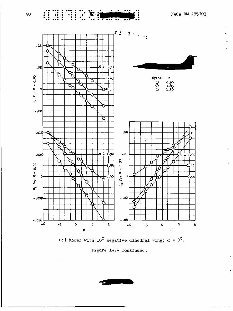
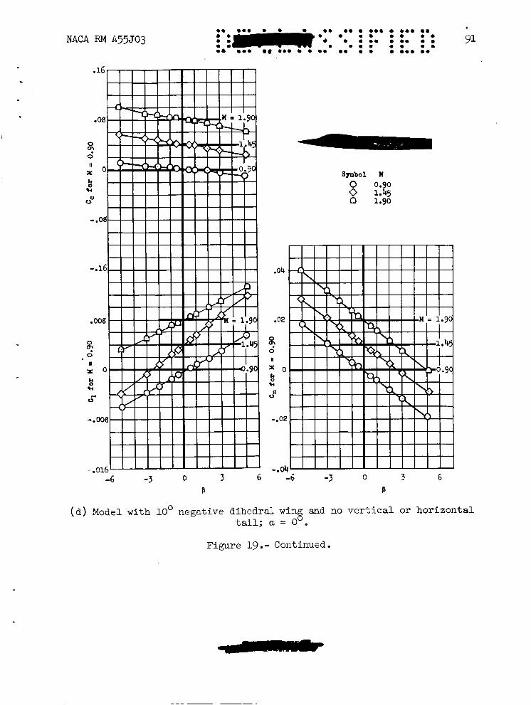
Results are presented which illustrate the effect of a dihedral angle change of from -5' to -10' on the lateral-directional stability characteristics of the complete model (figs. l9(a) and lg(c)) and the wing-body arrangement (figs. l9(b) and l9(d) ) son of two tail arrangements on the model (figs. l9(c) and l9(f)). The model with the lowered horizontal tail (fig. l9(f)) shows a decrease in directional stability which is slightly greater than would be expected due to the decrease in vertical-tail area. The dihedral effect resulting from lowering the horizontal tail was equivalent to a -5' change in wing dihedral angle at a Mach number of 0.9 and decreased with speed to about -1' at a Mach number of 1.9.
Also shown is a compari-
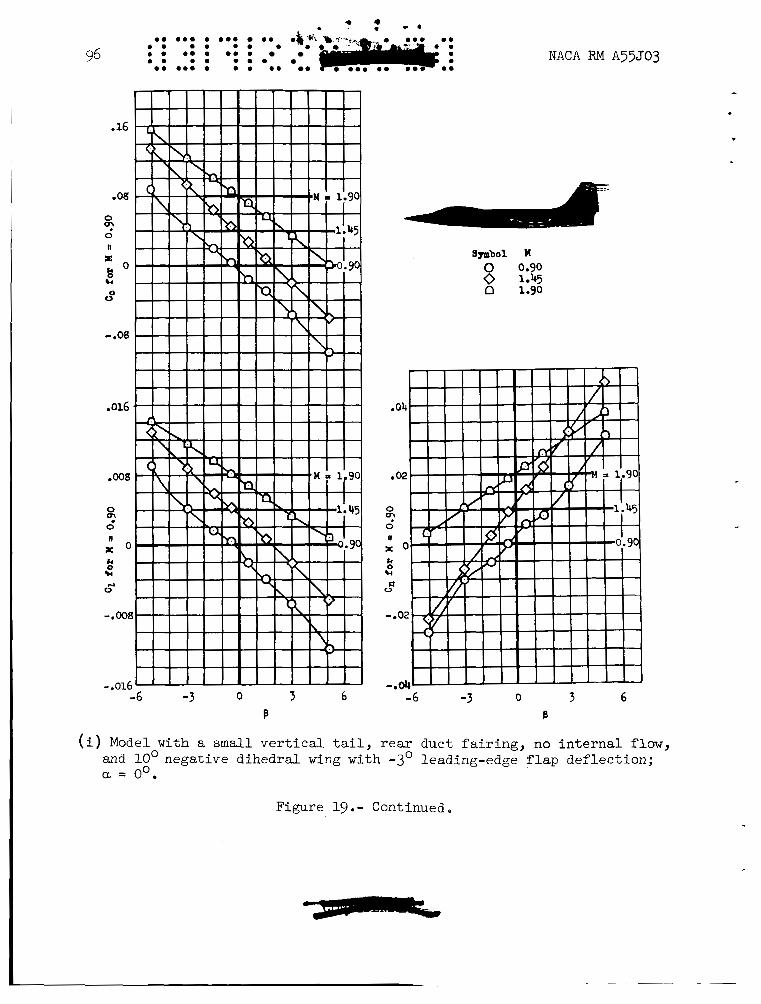
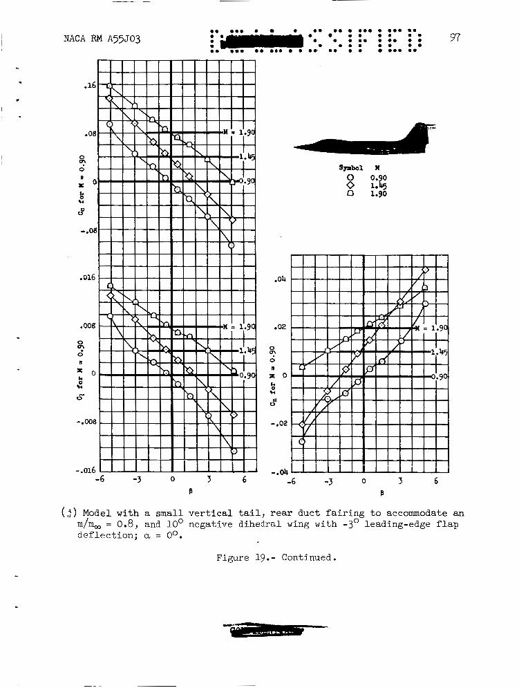
In order to investigate the lateral-directional stability character- istics of the model with air entering the side inlets, another model was constructed which incorporated certain modifications to allow for internal air flow. Comparison of the lateral-directional characteristics of the model with an internal mass-flow ratio of 0.8 (fig. l9( j)) and with the inlets faired closed (fig. l9(i)) showed a slight decrease in directional stability f o r the case of internal air flow. the result of the additional side loads carried by the inlets. This com- parison was made with the rear duct fairing in place. rear duct fairing on the aerodynamic characteristics of the model are shown by a comparison of figures l9( i) and l9( k) . duct fairing contribute a stable restoring moment to the model.
This effect was apparently
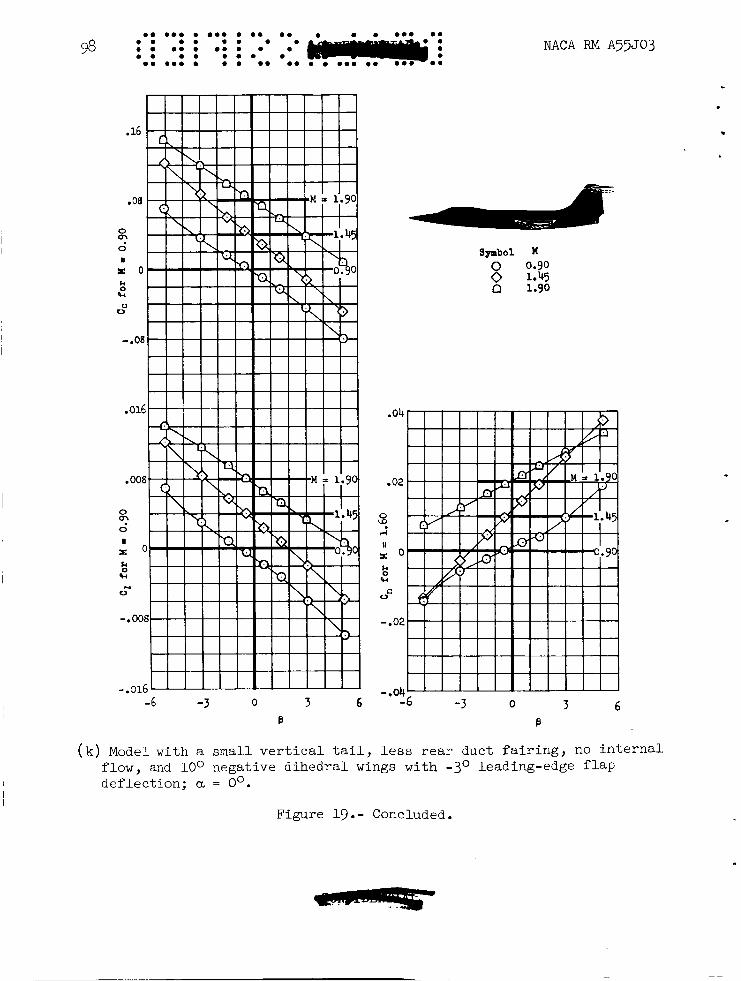
The effect of the
Side loads on the rear
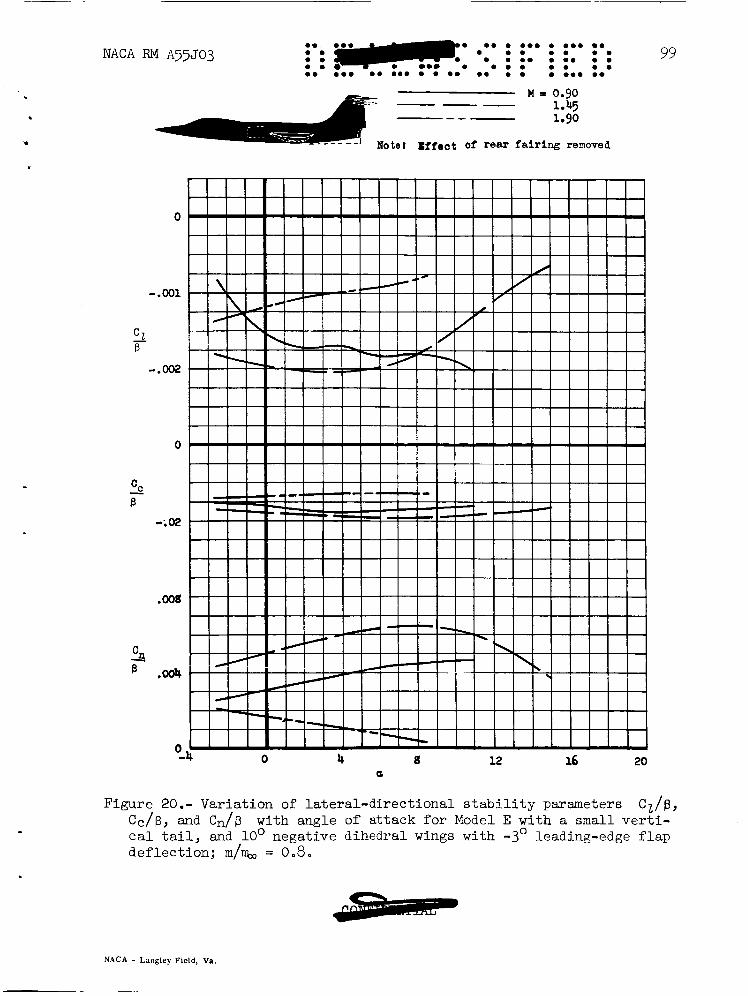
The effect of angle of attack on the lateral-directional stability parameters of Model E with internal air flow is presented in figure 20. Results obtained at Mach numbers of 0.9 and 1.45 show a progressive increase in directional stability with angle of attack up to angles of 7' or 8'. This type of variation with angle of attack results from the horizontal-tail-vertical-tail interference, and appears to be a charac- teristic effect of the high-mounted horizontal tail. Similar variations of the lateral-directional stability parameters with angle of attack are shown in the data for Model D with the high-mounted horizontal tail. decrease in directional stability with increasing angle of attack at a Mach number of 1.9 may be due to a combination of the decrease in end- plate effect at higher Mach numbers, and to the l o s s of vertical-tail effectiveness resulting from the air expansion over the wing. phenomenon was observed to affect the directional characteristics of Models A , B, and D at those Mach numbers where portions of the vertical tail were ahead of the shock wave emanating from the trailing edge Of
The
The latter
I the wing.
L
~
NACA RM A55503 15
C'ONCLUDING REMARKS
Examination of the aerodynamic parameters for several models inves- tigated show the following aerodynamic phenomena to be important in the determination of model characteristics:
1. The vorticity shed from the body may play a predominant part in the variation of directional stability with angle of attack at all Mach numbers for airplanes having a long slender body. In particular, the vorticity due to the side load on the body appears to be important in this respect.
2. The flow field generated by the upper surface of the wing? within which the air density is reduced, can influence the variation of directional stability with angle of attack. This effect was shown in these data as a decrease in directional stability with increasing angle of attack for those models with the vertical tail mounted close above the wing. This condition tends to become more severe as the Mach number increases.
3. The effect of the impingement of pressure disturbances from other portions of the airplane on the vertical surface appears important in determining di/rectional stability and is a factor to be considered, particularly for airplanes with nacelles or external stores. found that use may be made of the shielding effect of the wing to improve this condition.
It is
4. Large favorable end-plate effects of horizontal tails are found at transonic speeds but these favorable effects disappear at higher super- sonic Mach numbers since the Mach cone of the horizontal tail does not envelope a sizable portion of the vertical tail.
Ames Aeronautical Laboratory National Advisory Committee for Aeronautics
Moffett Field, Calif., Oct. 3, 1955
REFERENCES
1. Frick, Charles W., and Olson, Robert N.: Flow Studies in the Asym- metric Adjustable Nozzle of the Ames 6- by 6-~oot Supersonic Wind Tunnel. NACA RM AgE24, 1949.
16 NACA RM A55J03
* - . 2. Spahr, Richard J., and Dickey;- 3obBrt R . 9' Wind-Tunnel Investigation
of the Vortex Wake and Downwa>6'l%Eld 'Behind Triangular Wings and Wing-Body Combinations at Supersonic Speeds. NACA RM A53D10, 1953. I
3. Christensen, Frederik B.: An Experimental Investigation of Four Triangular-Wing-Body Combinations in Sideslip at Mach Numbers 0.6, 0.9, 1.4, and 1.7. NACA RM A33I22, 1954.
4. Jones, Arthur L., Spreiter, John R., and Alksne, Alberta: The Rolling Moment Due to Sideslip of Triangular, Trapezoidal, and Related Plan Forms in Supersonic Flow. NACA TN 1700, 1948.
5. Anderson, Adrien E.: An Investigation at Low Speed of a Large- Scale Triangular Wing of Aspect Ratio Two. - 11. "he Effect of Airfoil Section Modifications and the Determination of the Wake Downwash. NACA RM A7H28, 1947.
Jaquet, Byron M., and Brewer, Jack D.: 6. Effects of Various Out- board and Central Fins on Low-Speed Static-Stability and Rolling Characteristics of a Triangular-Wing Model. NACA RM ~9~18, 1949.
1 -
l 4
Model A
rlodif ied triangular
2.1
2.13
5.338
0.25 3.343
4.08
NACA RM A55J03
Model B
Modified triangular
2.02
I. .278
2.728
0.25 2.34
5 at root
. * D ..e t -
TABIE I.- PRIMARY GEOMETRIC CHARACTERISTICS OF TRE WIND-TUNNEL MODELS
0
60 0 3
0.712
50 84.5
1.073 1 -59 5.14
wing Plan form
0 * 332
52.5 0 0
0.468
52.5 50.6
0.878 1.46
3.278
Aspect ratio Mean aerodynamic chord, E , ft Moment center, span, ft Area, sq ft Thickness ratio, percent chord Camber
'Vertical tail Area, sq ft Leading-edge
Length, percent E sweep, deg
span, ft Aspect ratio
Taper ratio Sweepback of lead-
Dihedral, deg Incidence, deg
'Vertical tail Area, sq ft Leading-edge sweep, deg Length, percent span, ft Aspect ratio
Body length, ft
ing aeg
I4Ul.L
0.1758
50.5
0.507 1.46
122.4
b u l l
0.1958
47.13 121.2 0.528 1.42
b U l L
0.1816 0.1805 0.421 0.41:
12.5 50.4 38 44 115.3 124.0 138.0 135.7 0.519 0.545 0.729 0.66:
1.48 1.64 1.26 1.07
Model C
hiangular 3 -0
1.207 0.35
2 e699 2.425
3
0
0
53 -1 0 0
,.4188(tot+
53 67.1 0.60 1.72
3 * 910
Model D
lweptback 3.4
0 -495 0.287 1.493 0.662
I at root 5 at tip
0
0.25
47.2 -5 0
0.1758
50.5 122.4 0.507 1.5
2.121
Model E
Unswept 2.5
0.799 0.25 1.89
1.406 3 -4
0 and lead- ing -edge flap 6 = -3'
0.385
27 .I. -5 & -10
0
0.421
38 138.0
1.26 3.783
0 * 729
Geometric characteristics of the alternate vertical tails of Models D and E
I Model D I Model E
Characteristic I vE;?:a1
lWing incorporates conical camber with the leading edge offset 0.0286 b/2.
2Area of the vertical tail obtained by extending the leading and trailing The camber line becomes tangent to the chord plane at 0.85 b/2.
edges to the fuselage reference line.
18
I P C
0 - .0001 - .0002 .0001
.0002 - .0001 - .0001 - .0003 0 - .0001 - . 0001 - .0001 .OOOl
- .0001
'e., . i -
TABLE 11. - STREAM-IRREGU~ITY CORRECTIONS b
[These corrections apply only to the plots with able. rections to the results for the tail-off configurations are zero except f o r where they are the same as for the complete model.]
as the primary vari- Cor- They are to be added to the results for the complete model.
C z p
Model
A
B
D
E
Mach number
1.50 1.60 1.75 1 .go
1.25 1.40 1.65 1.90
1.20 1.40 1.60 1.90
1.90 1.45
~ Correction I
3.0001 0.0001 .0002 .0001 .0002 0 .0002 0
- .0002 - .0002 - .0002 0
.0002 0
.0003 .ooo4
- .0001 0 -.0001 .0005 .0001 .000E .0002 .ooo:
- .0001 - .000E .0002 .ooo:
NACA RM A55503
TABLE 111.- INDEX OF FIGURES
Moael - A
B
Subject material
General arrangement of the five models Dimensional sketch Detail of basic nacelles Detail of Siamese nacelles
cc, cz, c, -7s. B Besic model Less vertical tail Wing-chord-plane-mounted outboard nacelles Wing-chord-plane-mounted outboard nacelles Less vertical tail Pitched down 5' about their bases Toed in 5' With outboard port nacelles plugged
Less nacelles With Siamese nacelles With Siamese nacelles Less vertical tail
Inboard nacelles moved forward; outboard nacelles pitched up 5' and moved forward and inward
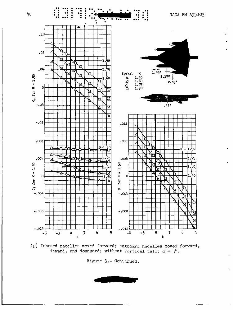
nacelles moved forward, inward, and downward
nacelles moved forward, inward, and downward
Inboard nacelles moved forward; outboard
Inboard nacelles moved forward; outboard
Less vertical tail Outboard port nacelle plugged
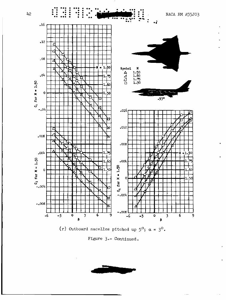
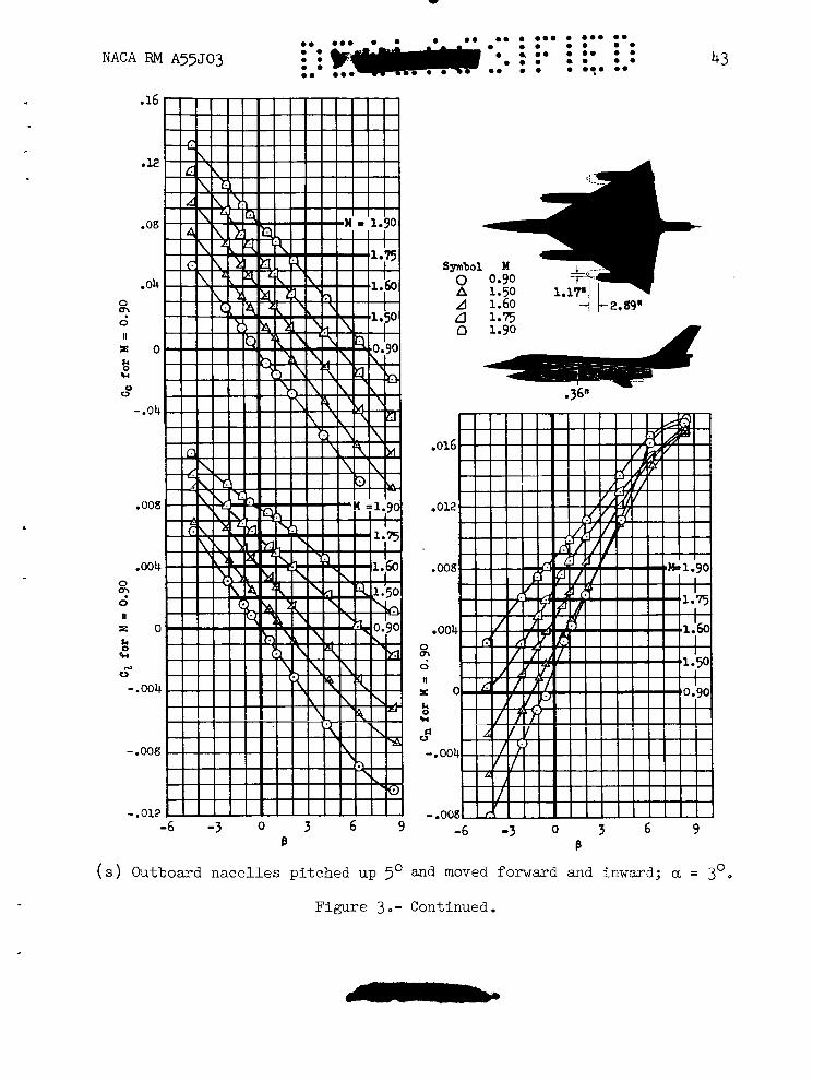
Outboard nacelles pitched up 5' Outboard nacelles pitched up 5 O and moved forward and inward Inboard nacelles moved forward and upward; outboard nacelles pitched up 5' and moved forward, inward, and downward
c',c", and 5 vs. a B B B
With Siamese nacelles
Complete model, less vertical tail, and
With Wing-chord-plane-mounted nacelles,
With basic inboard nacelles, with inboard
With wing-chord-plane-mounted nacelles at
With outboard nacelles moved downward,
wizn Siamese nacelles az TWO angies of
less nacelles
pitched down 5', and toed in 5'
nacelles forward
two angles of attack
forvard, and inward at two engles of attacl
attack ... ,.
Dimensional sketch
Basic Model
Basic Model
cct cz9 and c, B
Less vertical tail
Less vertical tail
2, 5, and 5 vs. a B B B Basic Model Less vertical tail
Czg, CcB, a d CnB VS. M
Ea ic Model . Fkith ,and wlthout the vertical tail With and without the vertical tail
2 g
3 3 3
3 3 3 3 3 3 0 3 3
a
3
7
3 3 3 3
3
5 to 9
3
3
3
3 and a 3 and 7
j ana 8
0 0 5 5
4 to 10 4 to a
0 5
B, deg
-4 to g -4 to g -4 to g -4 to g -4 to g -4 to g -4 to g -4 to g -4 to g -4 to g -4 to g -4 to g -4 to g
-4 to g
-4 to g
-4 to g -4 to g -4 to g -4 to 9
-4 to g
*5
0
0
0
0
0
U
-5 to 5 -5 to 5 -5 to 5 -5 to 5
*5 *5
0 0
Mach number
1.60, 1.75, 1.9 1.60, 1.75, 1.9
0 . 9 , 1.60. 1.75, 1.90 0 . 9 , 1.50, 1.63, 1.75, l.s 0.90; 1.60; 1.75; 1.90 1.50, 1.60, 1.75, 1.9 1.50, 1.60, 1.75, 1.9 1.50, 1.60, 1.75, 1.9
0 . 9 , 1.60, 1.75, 1.9 1.60, 1.9
1.60, 1.9 1.60, 1.9 1.50, 1.60, 1.75, 1.9
1.50, 1.60, 1.75, 1.9
1.50, 1.60, 1.75, 1.9
1.50, 1.60, 1.75, i.9 1.50, 1.60, 1.75, 1.9 1.50, 1.60, 1.75, 1.9 0.90, 1.52, 1.60, 1.75, 1.9
0.90, 1.60, 1.75, 1.9
1.60, 1.9
1.60 to 1.9
1.50 to 1.90
1.50 to 1.9
0.90 and 1.50 to 1.9
1.50 to 1.9
u .yJ and 1.h to 1.9
o . ~ , 1.25, 1.40, 1.65, 1.9 1.25, 1.40, 1.65 0.9, 1.25, 1.40, 1.65, 1.9 1.25, 1.40, 1.65
0.90, 1.25, 1.40, 1.65, 1.9 1.25, 1.40, 1.65
0.70 to 0 . 9 , 1.25 to 1.9 0.70 to 0 . 9 , 1.25 to 1.9
20 . . 0.. 0 . .e ... . 0.. . 0 . 0 . .
0 . e . .. . 0 . ... ... . 0 . 0 . 0 . .
0 . e.. . . . 0 . _. - ** f - * l * - TABLE 111.- INDEX OF FIGURES - Concluded
Subject material
Dimensional sketch
c, C1) and Cn VS. B
Basic Model Basic Model %sic M o d e l Dimensional sketch
c) '21, and C, VS. B Basic Model Less vertical and horizontal tail With Large-area vertical tail With unswept vertical tail
Less vertical and horizontal tail Basic Model
n vs. B Basic Model Basic Model Basic Model Basic Model Basic Model
Basic Model Less vertical and horizontal tail With tall vertical tail With unswept vertical tail
Less wing With high horizontal tail
Less vertical and horizontal tail spor-Screen Study
Less vertical and horizontal tail model Vapor screen at tail position Vapor screen at tail position Vapor screen at mid-fuselage
I ~ , Ccg, and CnB VS. M
With basic vertical tail, large vertical tall, unswept vertical tail, and less vertical &d horizontal tail
and horizontal tail With basic vertical tail, and less vertical
Dimensional sketch c , C1, and Cn VS. B
Basic Model Less vertical and horizontal tail With 10' negative dihedral wing
Less vertical and horizontal tail Less vertical and horizontal tail With small vertical tail With small vertical tail
Less horizontal tail With rear duct fairing and -3' wing leading-edge flap deflection, m/% = 0 With internal air flow of in/% = 0.8 Less rear duct fairing, m/% = 0
+, 5, and 5 vs. a B B With 10' negative dihedral wing, small vertical tail, -3' wing leading-edge flap deflection; mf- = 0.8
a, deg
0 5 10
0 0 0 0 10 10
and 10 and 10 and 10 ana 10 and 10
4 to 18 4 to 18 4 to 18 4 to 18 4 to 18 4 to 18 4 to 18
6 12 12
0
10
0 0 0 0 5 0 5 0 0
0 0
.3 to 1:
&
-6 to 8 -6 to 8 -6 to 8
-4 to 10 -4 to 10 -4 to 10 -4 to 10 -4 to 10 -4 to 10
-4 to 10 -4 to 10 -4 to 10 -4 to 10 -4 to 10
*5 *5 *5 *5 *5 *5 *5
5 5 5
0
0
-5 to 5 -5 to 5 -5 to 5 -5 to 5 -5 to 5 -5 to 5 -5 to 5 -5 to 5 -5 to 5
-5 to 5 -5 to 5
0 and 5
NACA RM A55J03
Eknch number
0.60, 0 . 9 , 1.40 0.60, 0 . 9 , 1.40 0.60, 0.9
0.9, 1.20, 1.40, 1.60, 1.9 0 . 9 , 1.20, 1.40, 1.60, 1.9
0 . 9 , 1.20, 1.40, 1.60, 1.9 0 . 9 , 1.20, 1.40, 1.60, 1.9 0 . 9 , 1.20, 1.40, 1.60, 1.90
0.90, 1.20, 1.40, 1.60, 1.9
0 . 9 1.20 1.40 1.60 1.9
0 . 9 , 1.20, 1.40, 1.60, 1.90 0.90, 1.20, 1.40, 1.60, 1.90 0.90, 1.20, 1.40, 1.60, 1.9 0 . 9 . 1.20, 1.40, 1.60, 1.9 0 . 9 , 1.20, 1.40, 1.60, 1.9 0.9, 1.20, 1.40, 1.60, 1.9 0.9, 1.20, 1.40, 1.60, 1.90
1.9 1.9 1.9
0.60 to 0 . 9 and 1.20 to 1.9
0.60 to 0 . 9 and 1.20 to 1.5
0 . 9 , 1.45, 1.9 0 . 9 , 1.45, 1.9 0 . 9 , 1.45, 1.9 0 . 9 , 1.45, 1.90 0 . 9 , 1.45, 1.90 0 . 9 , 1.45, 1.9
0 . 9 , 1.45, 1.90 0 . 9 , 1.45, 1.9
0 . 9 , 1.45, 1.90 0 . 9 , 1.45, 1.9
0.9, 1.45, 1.90
0 . 9 , 1.45, 1.90
NACA RM A55J03
rn - 0, 0
21
22
I
U 0
0 E
0 w
c
.- E 0 r 0
a (I) 0
c
+
- a
(I) 0 r V c .- c .- c B 0 s a
a c 0 a E 0
.-
E .- 0
- - a
NACA RM A55J03
ri a, a 0
V
E!
.ri cn cd PI n
cd - w
NACA RM ~55.~03
Inboard nocelle
23
Outboard n a c e l l e
( b ) De ta i l of basic nace l l e s .
Figure 2 Continued
24
Q C .- -
0 0 0 . 0 . 0 .0 . 0 . 0 . 0 0 0 0 . 0 0 0 . 0 0 . 0 0 0 0 0 . 0 0
0 . 0 0 . .
0) 0 C
Q t! e w-
P 0 r 0
0 c
2 u- 0
Q 0 0 Q
0 c 0 0 0)
0
.-
- .e-
t 2 I
-4
/
NACA RM A 5 5 5 0 3
3
.'
.12
.OB
.04
8 ri n E O
OV
k 0
Fc
- a 0 4
-.08
.012
.008
.004
$3 d
n r Q k 0 Fc Y 0
-.m
- .008 -6 -3 0 3 6 9
e
A 1.60
e
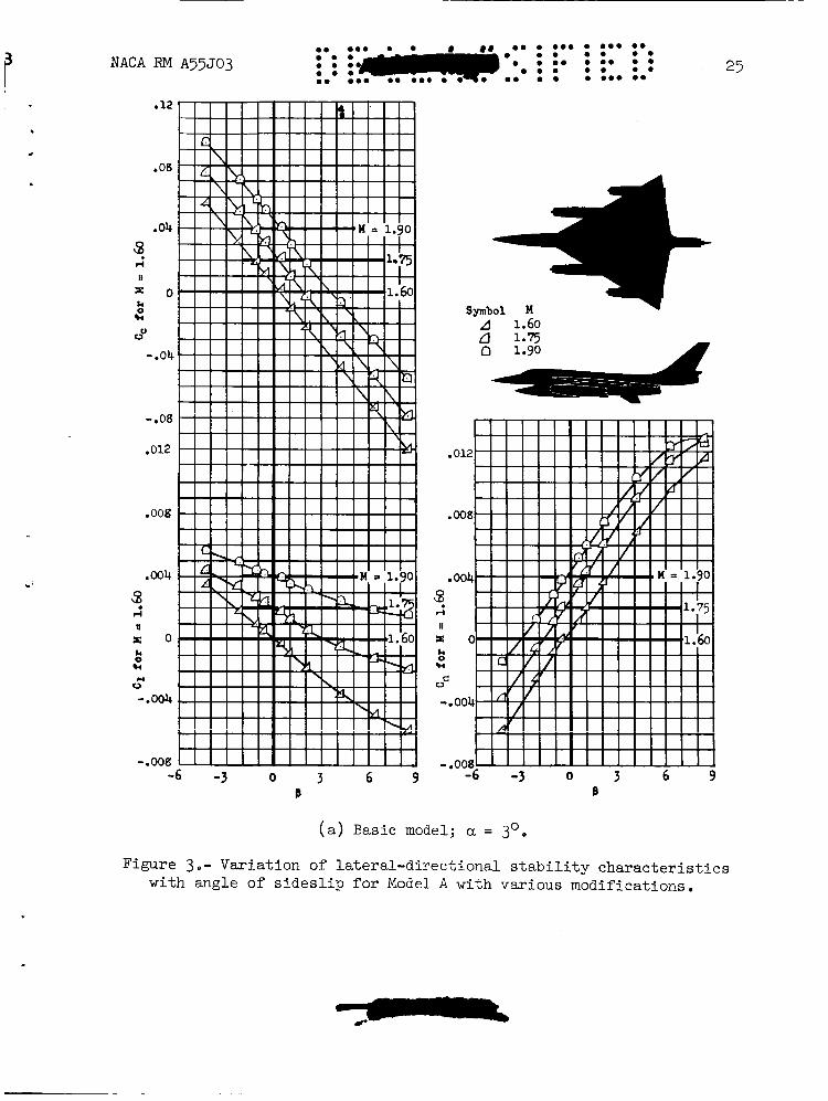
( a ) Basic model; a = 3 O .
Figure 3.- Variat ion of l a t e r a l - d i r e c t i o n a l s t a b i l i t y c h a r a c t e r i s t i c s wi th angle of s i d e s l i p f o r Model A with var ious modifications.
26 .e e.. e ..e e e. .e e.. e. : : e: : e i i
e . .. . .e* e. .e e.. . e e .e
.-a,-
-6 -3 o 3 6 9 B
NACA RM A55J03
Symbol M
n 1.75
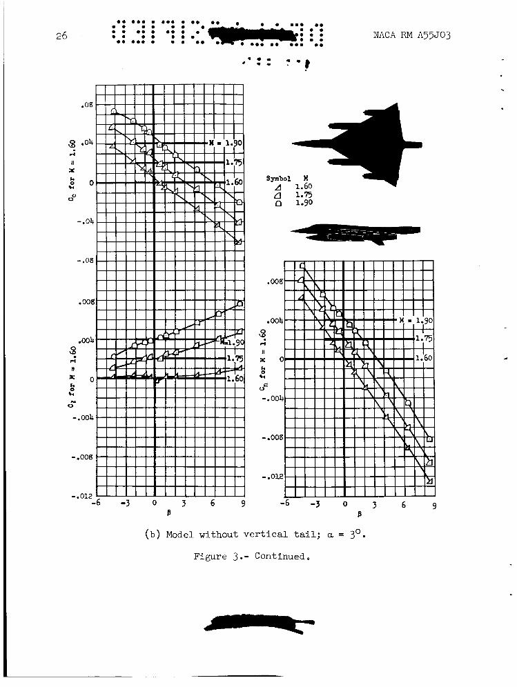
(b) Model without vertical tail; a = 3'.
Figure 3.- Continued.
' -
I -
NACA RM A55503 27
0 0.90
A 1.60
a 1.90
2.68" 1.2'
.016
e 0 1 2
e o 0 4 0
2 II
X O
Fd "S
-.004
o(
- .008 -6 -3 0 3
b
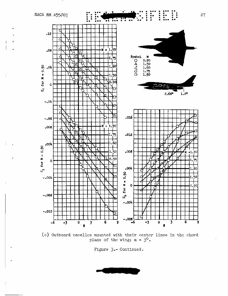
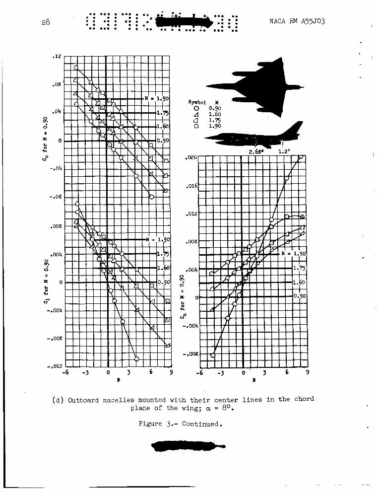
(c) Outboard nacelles mounted with their center lines in the chord plane of the wing; a = 3'. I
Figure 3. - Continued ~
28
.12
.04 0
2 II
= o k 0 k
0 0
- e 0 4
-.08
.008
004 0
0 II
02
E O % k
0 N
- 004
- e 0 0 8
- .012
0 0.90 A 1.60
2.68" 1.2"
-6 -3 0 3 6 9 B
( a ) Outboard nacelles mounted with their center lines in the chord plane of the wing; a = 80.
Figure 3.- Continued.
-6 -3 0 3 6 9 8
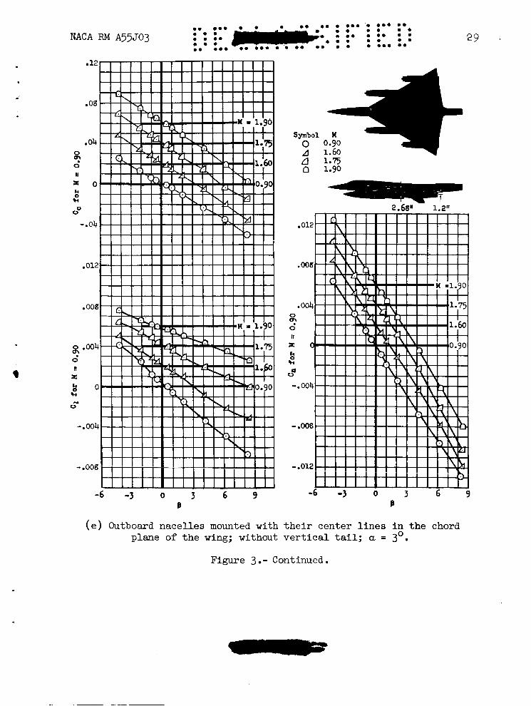
(e) Outboard nacelles mounted with their center lines in the chord plane of the wing; without vertical tail; a = 3 . 0
Figure 3 .- Continued.
30 e. *.. .e. e 0 . e. 0 . . 0.. ..
NACA RM A55J03 e . 0 . e. . . e o . e. 0 0 . 0 . ... e* ... . . 0 . . .
A 1.50 A 1.60
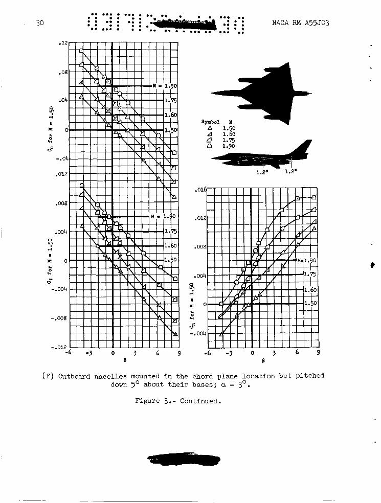
(f) Outboard nace l les mounted i n t h e chord plane l o c a t i o n bu t pi tched 0 down 5' about t h e i r bases; a = 3 .
Figure 3.- Continued.
c
symbol H A 1.50 A 1.60 a 1.5 n 1.90
2.68" 1.2"
-6 -3 0 3 6 9 B
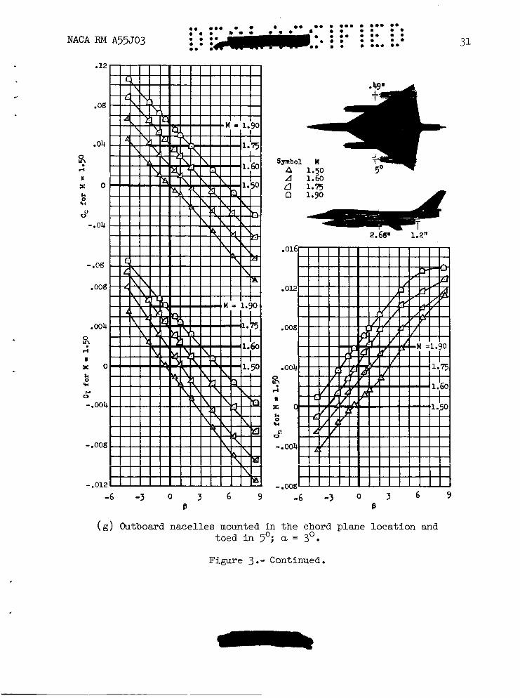
( g ) Outboard nace l les mounted in t h e chord plane loca t ion and toed i n 5'; a = 3'.
Figure 3. - Continued.
32
.12
.08
.04 0
r(
I!
9
E O k 0 FI
0"
- e 0 4
.012
. 008
,004 0
rl
W
u?
x o k
w
0 - - 004
-.008
-.012 1 1 I I I I I I I I I I -6 -3 0 3 6 9
8
.016
.012
.008
.m4 a
r O
rl
I
k 0 FI
0 d
- .004
-.ooa -6 -3 0 3
B
A 1.50 \
2.68 "
(h) Outboard nace l les mounted i n t h e chord plane l o c a t i o n with the 0 outboard p o r t nace l le plugged; a = 3 .
Figure 3.- Continued.
3 NACA RM A55503 33
.012
.004
8
X O
8
rl
I
*(
0 El
-e004
- .008 -3 0 3 6 9
B
(i) Model without nacelles; a = 3'.
Figure 3. - Continued
34
-6 -3 Q 3 6 9 B
' 0 0 . . e . 0 . . e.. . * *
NACA RM A55J03
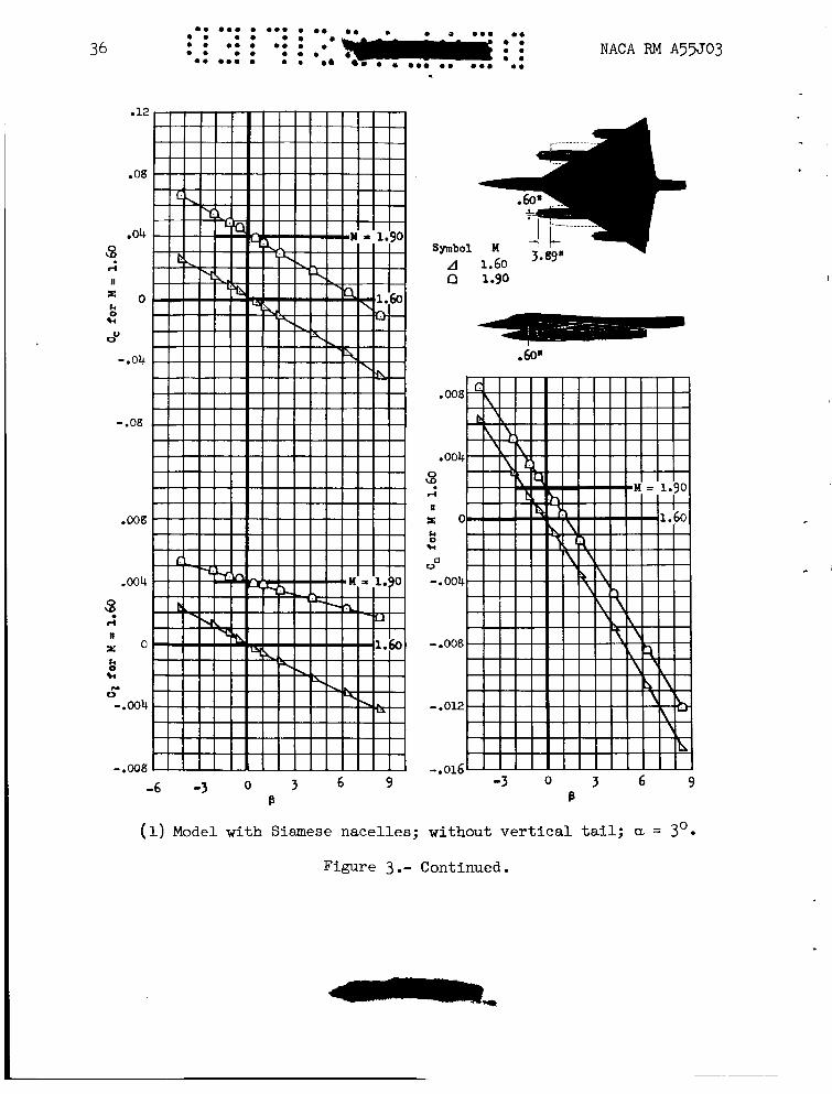
(j) Model with Siamese nacelles; a = 3'.
Figure 3.- Continued.
NACA RM A55J03
.OB
-04 3
E O
G ov
r(
I1
k
13 1.90
-.04
.ooa
,004
3 I4 n
X O 004
s k 0 w 0 N r(
n
Ld P
-.004 X O
w
- .oog - a 0 0 4
- .mz ~ n-9 - . V A L
-6 -3 O 3 6 9 -3 0 3 6 9 B B
35
( k ) Model with Siamese nace l les ; a = 8'.
Figure 3 . - Continued.
36
.12
.os
.04 8
E O
VV
rl
II
k 0 w
- e 0 4
- .08
.oos
.a4
3
r o
rl
I
k 0 w c 0 - .004
- .ooS
0 . . a 0 . 0 .
NACA RM A55503 0 .
(1) Model with Siamese nacelles; without vertical tail; a = 3'0
Figure 3.- Continued.
NACA RV A55J03
A 1.50 2.59" A Ll n
.36"
.016
.012
.008
.004
6 r(
1 r Q
0':
k 0 F,
-.004
-.Oog- . . . . . 3 6 9 -6 -3 0
8
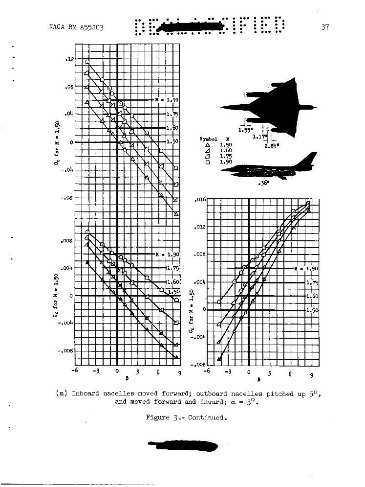
( m ) Inboard nace l les moved forward; outboard nace l l e s pi tched up 501 and moved forward and inwad; a = 3O.
37
Figure 3 o- Continued.
38 NACA RM A55J03
A 1-50 A 1.60 2.89"
J
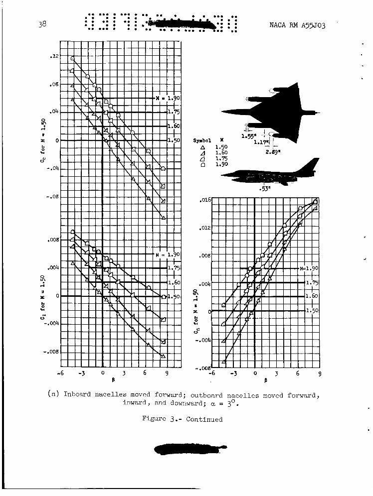
( n ) Inboard nace l l e s moved forward; outboard n a c e l l e s moved forward, inward, and downward; a = 3 0 .
Figure 3 .- Continued
.
NACA RM A55303 39
,
A 1.50 ---.-I t A 1.60 2.89"
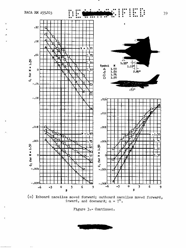
( 0 ) Inboard nace l l e s moved forward; outboard nace l les moved forward, inward, and downward; a = 7'.
Figure 3 * - Continued.
40 0 . . 0 . NACA RM A55J03
( p ) Inboard nace l l e s moved forward; outboard n a c e l l e s moved forward, inward, and downward; without v e r t i c a l ta i l ; a = 3'.
Figure 3.- Continued.
i3 NACA RM ~55503
.08
.04 0
ri
U
?
X O I4 0 k
0" - a 0 4
-.oa
,008
,004 0
ri U
";'
x o k 0 91
0 N
-.004
.. 008
-6 -3 0 3 6 9 B
- - - em oms e m
41
.
A 1.60
.53*
.012
.008
.004
a t-4
1 X O
8 cp k
-a004
- .008 -6 -3 0 3
B
( q) Inboard nace l les moved forward; outboard nace l l e s moved forward, inward, and downward; outboard po r t nace l le plugged; a, = 3'.
Figure 3 .- Continued
.16
12
.08
.Ob 0
4
II
u;'
X O
2 0"
k
-.Ob
.008
,004 0
4
I
?
> : o
c k
u 0 -.004
-.ma
-6 -3 Q 3 6 9 B
Symbol M A 1-50 A 1.60
.016
.012
,008
e004
8 rl
1 r O
ko
s. -.OOb
CI
- .008 -6 -3 Q 3 6 9
e ( r ) Outboard nace l les pi tched up 5'; a = 3 0
Figure 3.- Continued.
.
43
. .
1.60 A 1.75
-6 -3 0 3 6 9 B
0 ( s ) Outboard nacelles pitched up 5' and moved forwasd and inward; a = 3
Figure 3.- Continued.
44 0 . 0 0 0 0 0 0 0 0 0 . 0 . : : 0 : : 0 : ; ..e
0 . oop e o < * 0 0 0 .
0 . 0 0 0 0 0 0
.12
.OS
.04 0
0 II
Q:
x o k 0
%.4
0 rJ
- e 0 4
- .08 .008
.004 0
0 0: n x o k 0
%.4 M 0
- .004
- .008
-.012 - I ,
-6 -3 0 3 6 9 e
0 0 0 . 0 . 0 . NACA RM A55J03
0 0
-60" -14"
-6 -3 0 3 6 9 e
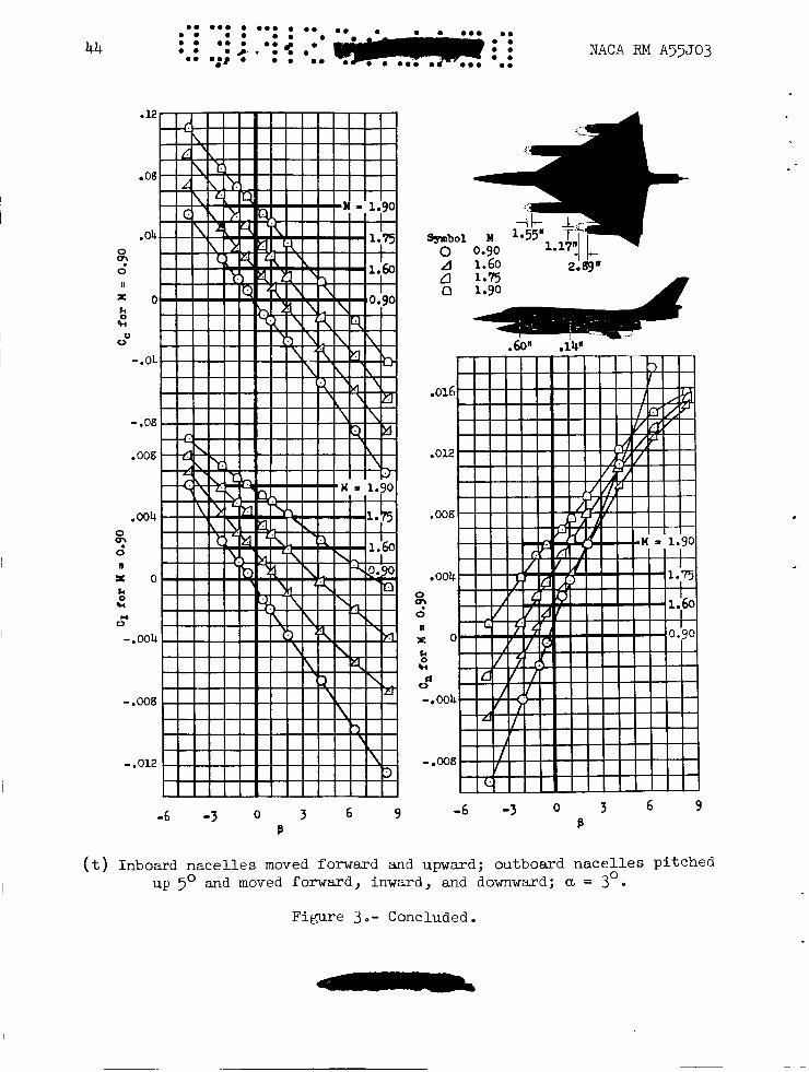
( t ) Inboard nace l l e s moved forward and upward; outbomd n a c e l l e s pi tched 0 up 5 O and moved fo rwad , inward, and downward; a = 3
Figure 3.- Concluded.
4
-6 -3 0 3 U
6 9
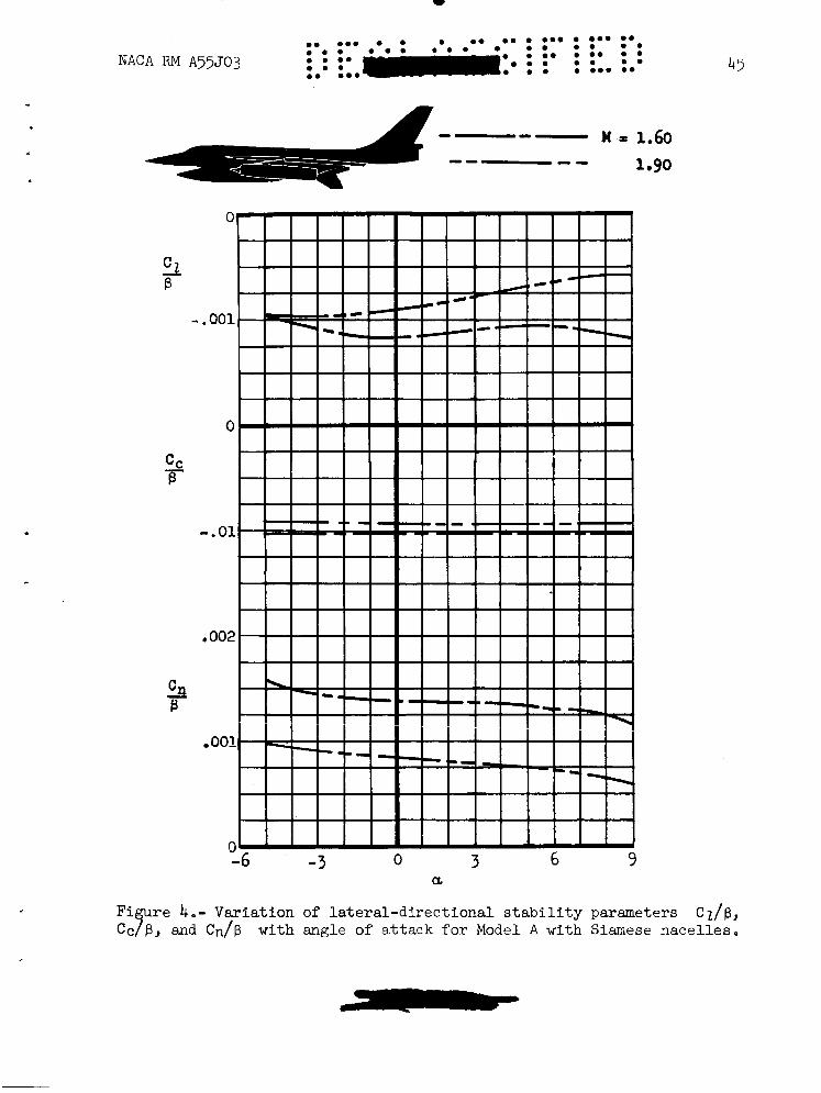
45
re 4.- Variation of lateral-directional stability parameters Cz/p, and Cn/p with angle of a t t a c k for Model A with Siamese nacelles.
"B C
46 NACA RM A35J03
(a) Complete model, model less vertical tail, and model less nacelles; a = 3'.
Figure 5.- Variation of lateral-directional stability derivatives with Mach number for Model A .
NACA RM A55J03 47
1.6 1.7 1.8 1.9 2.0 w
( b ) Outboard nace l l e s mounted i n the wing chord plane, showing t h e e f f e c t s of modifications t o the outboard nace l les ; a = 3 0 ,,
Figure 5 . - Continued
48 NACA RM A53J03
.O M
( c ) Outboard nace l l e s pylon mounted under the wing, showing t h e e f f e c t s of a chordwise s h i f t of t h e inboard nace l l e s ; a = 3 .
Figure 5 . - Continued.
0
B NACA RM A55J03 49
0.8 1.0 1.2 1.4 1.6 1.8 2.0
W
(d) Outboard nacelles mounted in the wing chord plane; a = 3' and 8'.
Figure 5. - Continued
NACA RM A55503
( e ) Inboard nace l l e s moved forward; outboard n a c e l l e s moved downward, forward, and inward; a = 3' and 7'.
Figure 5.- Continued.
NACA RM A55J03
0.8 1.0 1.2 1.4 1.6 1.8 2.0
( f ) Model with Siamese nace l les ; CL = 3' and 8'.
Figure 5 .- Concluded.
a
= a l z .E m E
m f
c m
c o 0 m u ) c m W W
.-
_- E Z u =
NACA RM A55J03
T t
i
NACA RM A55503
.12
.0g
-04
0
2 It
X O
k" k
0 0
-.Ob.
.016
.008 0
0 II
X
*(
i:
01'
g o N
-.ma
-6 -3 0 3 6 B
I
0 1.25 0 1.46 A 1.65 n 1.90
53
-6 -3 0 3 6 B
(a) Basic model; a = 0'.
Figure 7.- Variation of l a t e r a l - d i r e c t i o n a l s t a b i l i t y c h a r a c t e r i s t i c s with angle of s i d e s l i p for Model B.
-6 -3
-.008
- 0 3 6
B
Symbol W
o 1.25 0 1.40
1.65
-6 -3 0 3 6 B
(b) Model without vertical ta i l ; a = 0'.
Figure 7.- Continued.
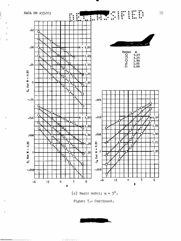
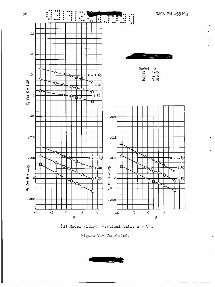
0 ( c ) Basic model; a = 5
Figure 7 .- Continued
n
~~ ~
-6 -3 0 3 6 -6 -3 0 3 6 B B
( d ) Model without v e r t i c a l tail; a = 3'.
Figure 7.- Concluded.
3 NACA RM A55J03
C A B
I -
57
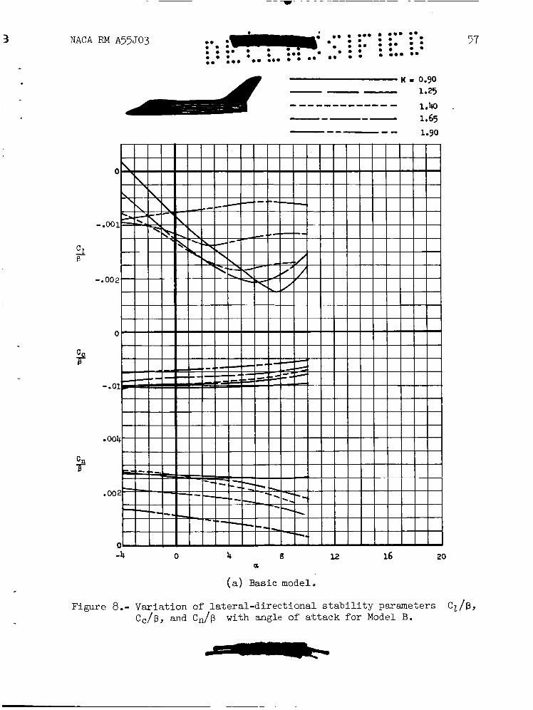
-4 0 4 g 12 16 20 5
(a) Basic model.
Figure 8.- Variat ion of l a t e r a l - d i r e c t i o n a l s t a b i l i t y parameters C,/p, Cc/p, and C n / p with angle of a t t a c k f o r Model B.
am mom o m m 0 0 m * m :*i
m a m m m m m m m e m a m o m
am mmo ma ma om. eo m o m em
NACA RM A55J03
a
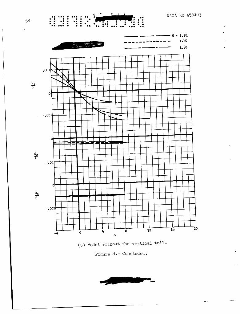
(b) Model without the vertical t a i l .
Figure 8.- Concluded.
NACA RM A55J03
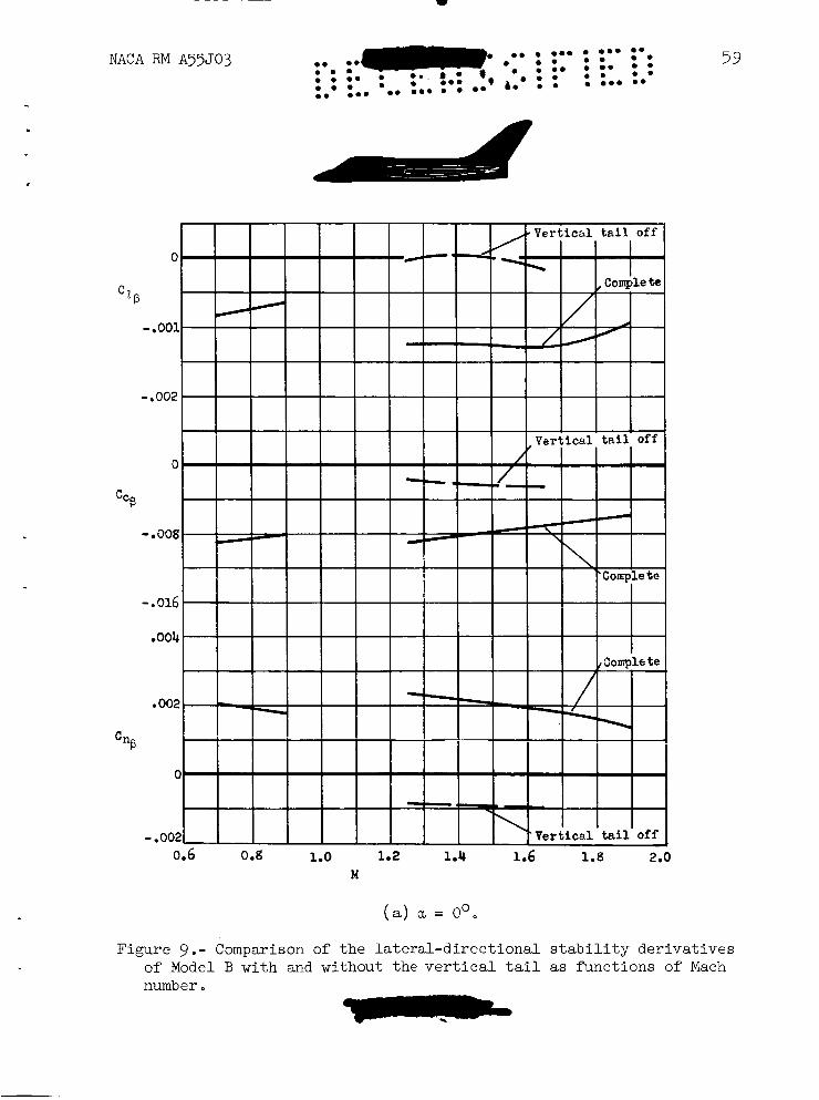
0.6 0.g 1.0 1.2 1.4 1.6 1.8 2.0 H
(a) a = 0'.
Figure 9.- Comparison of the lateral-directional stability derivatives of Model B with and without the vertical tail as functions of Mach number
60 NACA RM A55J03
(b) a = 5 O .
Figure 9 .- Concluded.
~~ ~
NACA RM ~55J03
\ -
I
I, .I' I
7-
61
V
k 0
I . 0 rl
.
.12
. og
.04
8
a 0
"0
I1 E
0 91
-.Ob
.012
.oog
.004
0
I1 '0,
= o k 0 91 m 0
-.004
-.00S
- .012 -6 -3 O 3 6 9
B
0 0.60 0 0.90 0 1.40
( a ) a = 0'.
NACA RM A55J03
Figure 11.- Variat ion of l a t e r a l - d i r e c t i o n a l s t a b i l i t y c h a r a c t e r i s t i c s with angle of s i d e s l i p for Model C a t d i f f e r e n t angles of a t t ack .
NACA RM A55J03
( b ) a = 500
Symbol M
0 0.60 0 0.90 0 1.40
.01
.01
.oo
. 00 s i
2 "C
E k
-.oo
- .OO
-.01
Figure 11 .- Continued
64
.12
.OB
.04
s II z k o 0 +I
0 0
-.04
.012
. 008
.004
s n
ZC k o 0 +I
PA 0
-.004
-.008
- .012
NACA RM A55J03
spabol n
0 0.60
0 0.90
( c ) a = loo.
Figure 11.- Concluded.
NACA RM A55J03 am am a a a a a a a a am
a . a a m a m a a a a a a a a a m
a a a a a a a a e a a a a m m a .a a a a am a a a a a ma am a a a a a e me
m
8 5 .E 0 3 C L L o w
L o o C 0
f
.- E : 48s E 5 a
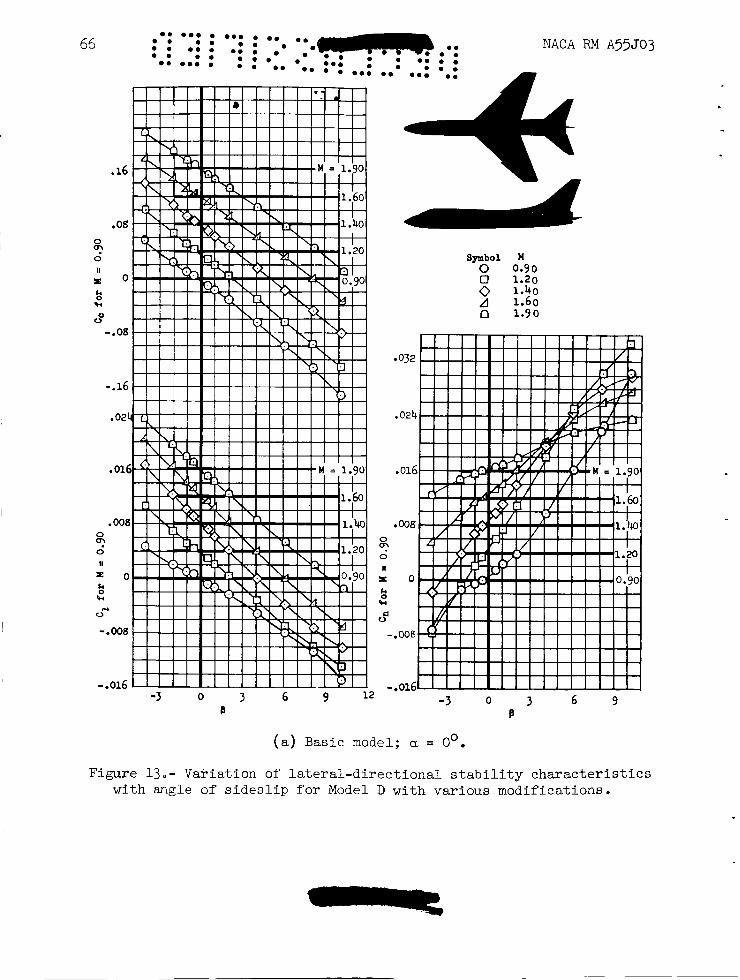
Figure 13.- VaPiation of l a t e r a l - d i r e c t i o n a l s t a b i l i t y c h a r a c t e r i s t i c s with angle of s i d e s l i p f o r Model D with var ious modifications.
67
B B
( b ) Model without v e r t i c a l o r ho r i zon ta l ta i l ; a = 0 . 0
Figure 13. - Continued.
-3 0 3 6 9 12 B
( c ) Model with large area v e r t i c a l t a i l ; a = 0'.
Figure 13.- Continued.
Symbol M 0 0.90 0 1.20 0 1.bo A 1.60 n 1.90
-3 0 3 6 9 -.or6
B
NACA RM A55J03 .. e., e. @*. 4 i. .e 0 0 0 .*. ..
Symbol I4 0 0.90 0 1.20 0 1.40 .4 1.60 n 1.90
0 (a) Model with unswept v e r t i c a l t a i l ; a = 0 . Figure 13 .- Continued.
.24
.16
.08
0
0
E k 0 w 0
Q?
" 0
0
-.08
-.16
.024
.016
. 008 0
2 11
E O
w
0 u
-.W8
-.016
-3 0 3 e
NACA RM A55J03
Symbol W 0 0.90 0 1.20 0 1.40 A 1.60 13 1.90
.016
.008 0 : II
x o k d Fi
0
-.ooa
-3 0 3 6 9 -.016~' I I - ' ' I I I I I I I I
e ( e ) Basic model; a = 10 0
Figure 13.- Continued.
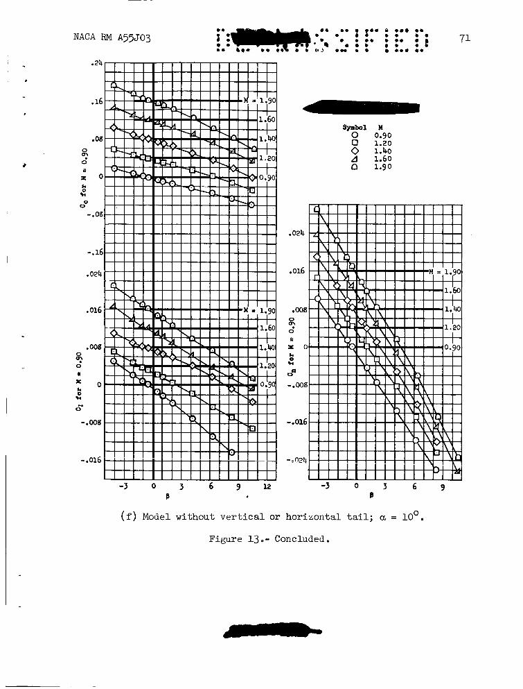
0 ( f ) Model without v e r t i c a l o r hor izonta l t a i l ; a = 10
Figure 13 - Concluded.
NACA RM A35J03
(a) M = 0.90
Figure 14.- Variation of the yawing-moment coefficient, Cn, with angle of sideslip for Model D at two angles of attack.
,
B
I "
I 1
I
I
NACA RM A 5 5 J 0 3 73
Figure 14.- Continued
NACA RM A55J03 74
0 u-00 0 u = loo
( c ) M= 1.40
Figure 14.- Continued.
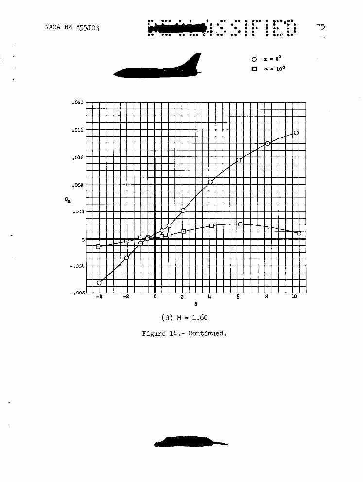
( a ) M = 1.60
Figure 14 Continued
0 a - 0 '
a = loo
.020
.016
.012
,008
.004
Cn
0
-. 004
- .008 -4 -2 0 0
o a = o O O a - 10'
NACA RM A55J03
Figure 14.- Concluded.
0
-.002
-. 004
0
- .02
.002
0
-.002
(a) Basic model.
Figure 15.- Variation of lateral-directional stability parameters Cz/p, Cc/p, and Cn/B various modifications.
with angle of attack for Model D with
77
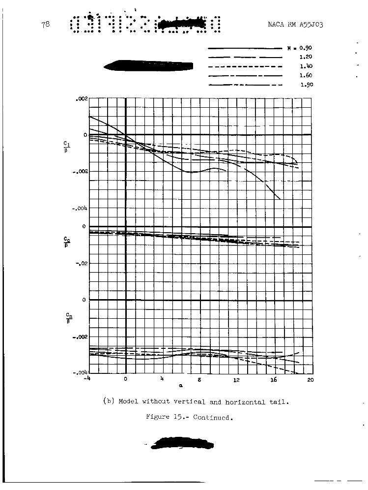
(b) Model without vertical and horizontal tail.
Figure 15.- Continued.
NACA RM A55JQ3
- C1 B
- Cn B
-4 0 4 8 12 16 20 a
(c) Model with tall vertical tail.
Figure 15 .- Continued.
NACA RM A35J03
-- -- 1.90 0
- C 1
- ,002 P
0
C C
T-
- .02
004
.002
- Cn B
0
-.002
1 1 1 1 1 1 1 1 1 1 1 1 1 1 1 1 1 1 1 1 1 1 1 1 1 -4 0 4 a 12 16 20
a
( a ) Model with unswept vertical tail.
Figure 15 .- Continued.
1B
(e) Model with horizontal tail placed high on the unswept vertical tail.
Figure 15. - Continued.
~9 m o l : -9 : : e..
e. m o e a .a e o DO. O D 0.9 0 0
NACA RM A55t e m a * e . . e . . m m m e 0 0 .
- M LI 0.90 - 1.20 --------- 1.40 ,-,---- 1.60
1.90 1- -- L-
0 4 8 12 16 20 a
( f ) Model l e s s wing.
Figure 15. - Continued.
JO3
NACA RM A55J03 me om e me. e worn em
e m 0 0 o m -".& :*- - e o 0 0 & a
83 S 0 0 0 B O . 0 0
- 0 e.. m. * e * 0 0 .e m e 0 0 w ..e 0 0
4 12 a
( g ) Model l e s s wing and empennage.
Figure 15 .- Concluded
16 20
Vapor
Vapor --- screen - - - -
NACA RM A55503
$62-
Wing t i p vortices
(a) u = 6 O , p = 5'
Wing t i p v o r t i
Body vor t ices
P:
Body vor t ices
( c ) a, = lpO, p = 50 A-20030-1
Figure 16,- Vapor screen study of Model D; model l e s s v e r t i c a l and hor izonta l t a i l ; Mach number 1-90.
NACA RM A55503 85
(a ) Body-wing model; model with basic v e r t i c a l t a i l unswept v e r t i c a l t a i l , and l a r g e r v e r t i c a l t a i l ; a = 0 6 .
Figure 17.- Comparison of t he l a t e ra l -d i r ec t iona l s t a b i l i t y de r iva t ives of Model D with var ious modifications as funct ions of Mach number.
M
( b ) Body-wing model and b a s i c model; a = 10'.
Figure 17.- Concluded.
NACA RM A55503
l -
NACA RM A55503
I
I
I I V-
-6 -3 0 3 6 B
Symbol U 0 0.90 0 1.b D 1.90
B
0 (a) Basic model; a, = 0 . Figure 19.- Variation of lateral-directional stability characteristics
with angle of sideslip of Model E with various modifications.
2B NACA RM A55J03 00 0 om. 0.0 0 0
0 0 . 0 0 0 . 0 . . 4 0 0 0 .
0 . 0 0 0 m . 89 .. 0 0.0 0 0
Symbol bl 0.90 8 1.45 n 1.90
0 (b) Model without vertical and horizontal tail; a = 0 .
Figure 19. - Continued.
a. * a * a * * a a .a a. *a. a.
90 : a . : a: 0 . : a t * * a : a * F . ; m : a. *a. a a a .a a. a a ..a a. * a * .a
( c ) Model with 10' nega
Figure 19.
.04
- .02
-.04
NACA RM A55J03
.
Symbol H 0.90 8 1.45 a 1.90
-6 -3 0 3 6 B
. t ive dihedral wing; a = 0'.
- Continued.
NACA RM A55503
I I 1 1 - m C ,
-.”..I
-6 -3 0 3 6 B
Symbol M 0 0.90 0 1.45 D 1.90
-6 -3 0 3 B
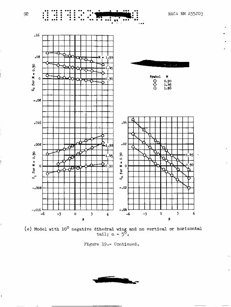
( d ) Model with 10’ negative d ihedra l wing and no v e r t i c a l or hor i zon ta l t a i l ; a = 0’.
Figure 19. - Continued.
e. ea . e o e e e o e o e e o o e we o e e e o e e e e e e 0 0 . e e ~ e e e e a . e o e e e e .. 92
.16
.08
0
0 I1
9'
P o 0 w 0
0
- .08
.016
.008
0
2 II
E O k 0 w
0 .4
-.008
-.016 -6 -3 0 3 6
B
NACA RM A55J03
.
Symbol H 0 0.90 0 1.45 n 1.90
.04
.02
0
0 II
o!
x o k 0 w
EI 0
-.02
-.04 -6 -3 0 3 6
B
( e > Model with 10' negative d ihedra l wing and no v e r t i c a l or hor izonta l t a i l ; a =
Figure 19.- Continued.
NACA RM A55503
-6 -3 0 3 6 B
Symbol If 0 0.90 0 1.45 n 1.90
3 6 -b -3 0
B
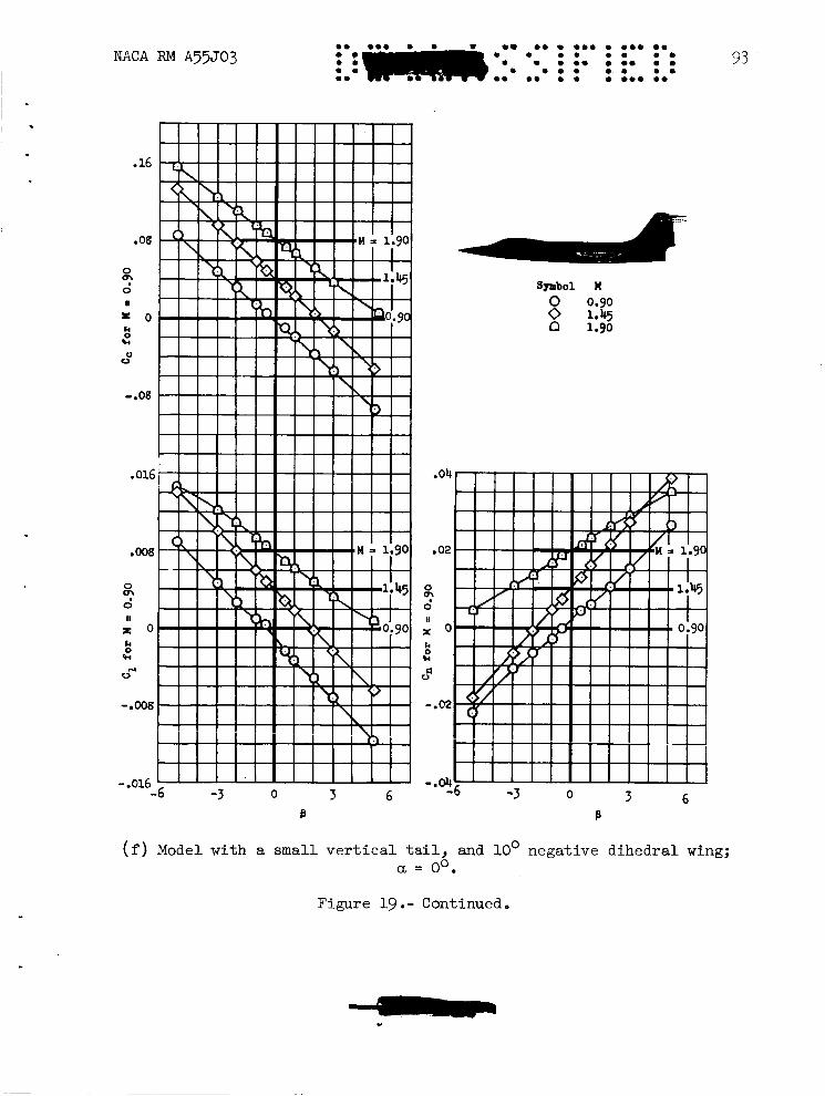
(f) Model with a small v e r t i c a l t a i l , and 10' negative dihedral wing; a = oO.
Figure 19 .- Continued
-6 -3 0 3 6 B
NACA FU4 A55503
Symbol , H 0.90 8 1.45 n 1.90
-6 -3 0 3 6 B
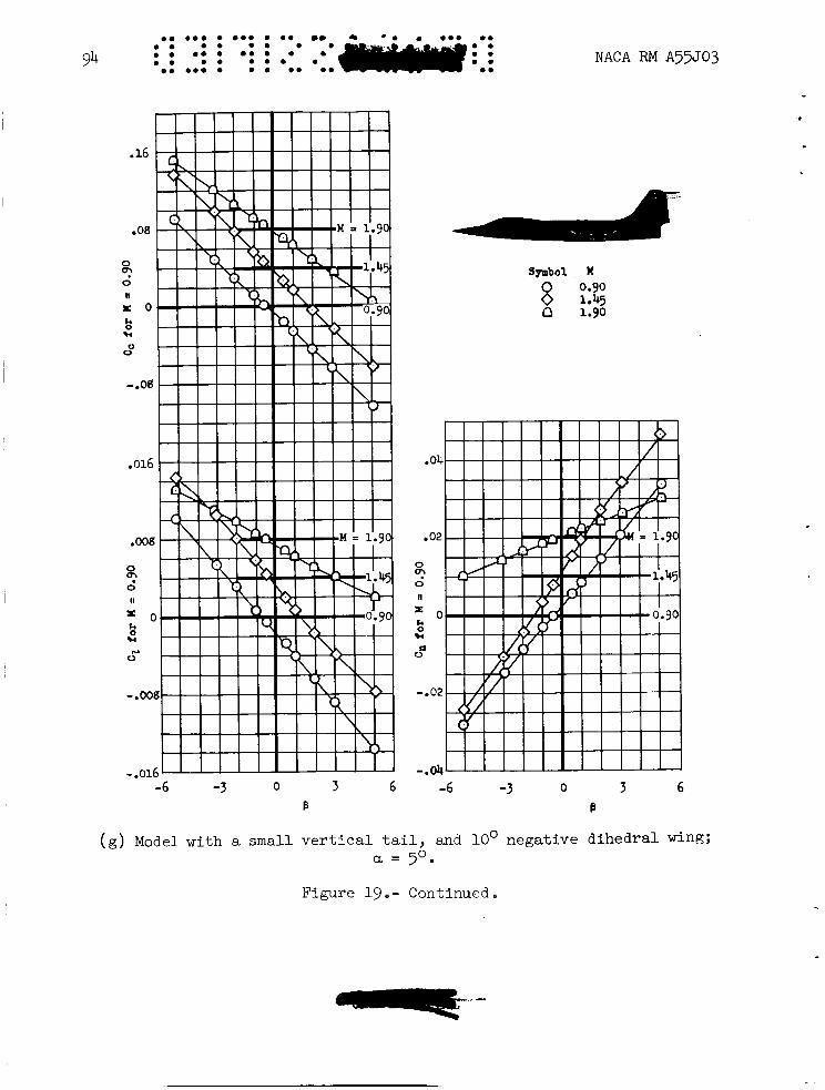
( g ) Model with a small v e r t i c a l t a i l , and 10' negat ive d i h e d r a l wing; a = 50.
Figure 19 o - Continued
NACA RM A55503 t
95 m. . ... . e.. .. . 0 . .. 0 . . 0 . . 0 . . 0 . . e.. 0 . 0 . 0 . . . ..e 0 .
symbol t! 0 0.90 0 1.45 o 1.90
.16
.08
0
0
U
02
X O
!i! OV
-.og
k
.04 -.16
.008 .02
02 m
X O x o !i! k
0
0 II
0
0 II
w d 0
k
0 rJ
-.ooel -.02
-.016 -.04 -6 -3 0 3 6 -6 -3 0 3 6
B B
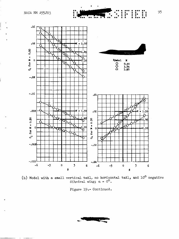
( h ) Model with a small v e r t i c a l tail, no hor i zon ta l t a i l , and 10' negat ive 0 dihedra l wing; a = 0
Figure 19 .- Continued.
0 . . ? r e ma moo 0 0 0 . ma
o m o m a m m e ' o m o m 0 o m m m o a m a m 0
am m o m 0 0 0 0 0 96 NACA RM A55J03
Symbol M 0.90 8 1.45 n 1.90
-6 -3 0 3 6 B
(i) Model with a small v e r t i c a l t a i l , r e a r duct f a i r i n g , no internal flow, and 10' negative d ihedra l wing with -3' leading-edge f l a p def lect ion; a = oo.
Figure 19.- Continued.
ee e e e e e em e e e e e e e e e e em 97 e e e e e m
e e e . . e * * e . e * e * e * e .
NACA RM A55503 m e s e e e e ea. e e e m e e e e eee e e
.16
.oa
0
0 Q;'
i o 8 k
u 0
-.os
.016
.008
0
0 s' n
= o
s k 0 w
-.008
I ! I I 111-1 -.016 1 I I I I I I ' ' ' '
0 3 6 -6 -3 B
.04
.02
0
0
II
a'
r O
ko +l
la 0
-.02
-.04
Symbol U 0 0.90 0 1.45 [3 1.90
-6 -3 0 3 6 B
(j) Model with a small vertical tail, rear duct fairing to accommodate an m/m, = 0.8, and 10' negative dihedral wing with -3' leading-edge flap deflection; a = Oo.
Figure 19. - Continued.
ma .am a a a a a ma a. a a a a a a a.
NACA RM A’j3J03
t
Symbol 0.90 8 1.45
n 1.90
.04
.02 *
3
X O
Fd
PI
II
+4
0 C
-.02
-.a -3 0 3 6
B
-6
(k) Model with a small vertical tail, less rear duct fairing, no internal flow, and loo negative dihedral wings with - 3 O leading-edge flap deflection; a = Oo.
Figure 19.- Concluded.
.
. V
-- M = 0.90
0
-.001
0
0 -4 0 4 8 12 16 20
U
Figure 20.- Variat ion of l a t e r a l - d i r e c t i o n a l s t a b i l i t y parameters C,/p, Cc/p, and Cn/p with angle of a t tack for Model E with a small v e r t i - cal t a i l , and loo negative dihedral wings with -3' leading-edge f l a p def lec t ion ; m / h = 0.8.
NACA - Langley Field, Va.
~~~