Embed Size (px)
Citation preview
Çukurova Üniversitesi Mühendislik Mimarlık Fakültesi Dergisi, 32(3), ss. 227-241, Eylül 2017 Çukurova University Journal of the Faculty of Engineering and Architecture, 32(3), pp. 227-241, September 2017
Ç.Ü. Müh. Mim. Fak. Dergisi, 32(3), Eylül 2017 227
Stator Feedforward Voltage Estimation Based Sensorless Permanent
Magnet Synchronous Generator Drive using Multi-Parameter
Estimation Based on MRAS
Ömer Cihan KIVANÇ
1, Salih Barış ÖZTÜRK
*1
1Okan Üniversitesi, Mühendislik Fakültesi, Elektrik-Elektronik Mühendisliği Bölümü, İstanbul
Geliş tarihi: 17.05.2017 Kabul tarihi: 25.09.2017
Abstract
A simple and efficient position sensorless control method based on feedforward voltage estimation for
PMSG improved with multi-parameter estimation using MRAS is proposed in this paper. The
dynamically enhanced stator feedforward dq‒axes voltages that are derived from steady-state PMSG
model are modified for the sensorless drive. In direct-drive wind turbine systems, because of low back-
EMF amplitude in the generator output at very low speed operation, the rotor flux linkage cannot be
predicted correctly. Vector control is often used in PMSG control, because it has a simple structure and is
suitable for various industrial systems. In the power equation, maximum power is obtained as a function
of torque and speed. In the proposed method, a variable-speed wind turbine system with back to back
converter structure is connected to common DC-link. In this paper, the proposed sensorless control
scheme has been implemented with 1 kW PMSG drive controlled by a TMS320F28335 DSP for low
speed at 0.1 p.u. (300 rpm) is achieved under multi-parameter variations.
Keywords: Model reference adaptive system (MRAS), PMSG, Sensorless control, Feedforward voltage
estimation, Multi-parameter estimation
MRAS Tabanlı Çoklu-Parametre Tahmini ile Güçlendirilmiş İleri Beslemeli Stator
Gerilim Tahminine Dayanan Sensörsüz Sürekli Mıknatıslı Senkron Generatör
Kontrolü
Öz
Bu makalede MRAS tabanlı çoklu-parametre tahmini ile güçlendirilmiş ileri beslemeli stator gerilim
tahminine dayanan basit ve verimli bir sensörsüz sürekli mıknatıslı senkron generatör (SMSG) kontrol
metodu geliştirilmiştir. Sürekli mıknatıslı senkron generatörün sürekli hal dq‒ekseni stator gerilim
eşitlikleri önerilen kontrol metoduna uygun olarak ileri beslemeli stator gerilim eşitlikleri haline
*Sorumlu yazar (Corresponding author): Salih Barış ÖZTÜRK, [email protected]
Stator Feedforward Voltage Estimation Based Sensorless Permanent Magnet Synchronous Generator Drive using
Multi-parameter Estimation Based on MRA
228 Ç.Ü. Müh. Mim. Fak. Dergisi, 32(3), Eylül 2017
dönüştürülmektedir. Çeşitli endütriyel uygulamalar için uygun ve basit bir yapısı olması nedeniyle
SMSG’nin kontrolünde vektör kontrol sıkça kullanılmaktadır. Güç eşitliğinde maksimum güç, moment ve
hızın bir fonksiyonu olarak ifade edilir. Önerilen yöntemde, arka arkaya bağlı konvertör yapısına sahip
değişken hızlı rüzgar türbini sistemi, ortak DC-baraya bağlanmıştır. Bu makalede, önerilen sensörsüz
kontrol metodu TMS320F28335 DSP tarafından kontrol edilen 1 kW PMSG sürücü ile gerçek zamanlı
deneysel olarak nominal hızın %10’u (300 rpm) değerindeki düşük hızda çoklu parametre değişimi
altında başarı ile gerçekleştirilmiştir.
Anahtar Kelimeler: Model referans adaptif sistem (MRAS), SMSG, Sensörsüz kontrol, İleri beslemeli
gerilim tahmini, Çoklu parametre tahmini
1. INTRODUCTION
The difference between fossil energy sources and
demanded energy needs is rapidly increasing. This
increase leads to alternative search and solutions in
energy production. With the integration of smart
grid to energy production at the macro level,
individual energy production is supported by
companies and governments [1]. Utilization of the
wind turbines in small energy production is
increasing rapidly. In US, the small wind turbine
market shares in 2014 reached $60 million. In
England, energy capacity of wind turbines ranging
between 0 and 1.5 kW is recorded as 1.84 MW in
2013. In small wind turbines, Permanent Magnet
Synchronous Generator (PMSG) is preferred for
high performance, high power density, reliability,
and high efficiency. The outer rotor and the inner
rotor PMS generators that have axial flow
direction are used in various industries with wide
power ranges as direct-drive [2]. In small PMSG
systems that generate less than or equal 10 kW
power, there is no need for gearbox and the
connection can be made directly to the turbine [2–
[10]. This is an important factor lowering the cost
in small wind turbine systems [8–10]. PMSG is
suitable for wind power generation allowing
maximum power generation in a wide speed range
and at different wind speeds [11]. Efficient wind
turbine system can be constructed by adjusting the
speed of the generator shaft optimally for variable
wind speeds at maximum power operating point
[12]. In variable-speed PMSG control, it is
required to know the rotor position information
and wind speed [13]. Because the working
conditions of the turbine changes so often, changes
in speed and torque reduce the control
performance. Moreover, in order to ensure power
generation at wide speed range, sensitive and high
resolution position control is performed by
encoder, resolver or hall sensors. On the other
hand, sensorless PMSG control can be
accomplished without using position sensors [10].
In the control of PMSGs, with the elimination of
the position sensor, cost, maintenance and
robustness problems of the overall system are
reduced [8–10]. Because no initial position
problem and operating at flux-weakening region
exist, sensorless control is a significant cost
reductive solution for the control of PMSG drives.
Determining the wind speed and rotor position can
be accomplished with the methods which are
Direct Torque Control (DTC), Model Reference
Adaptive System (MRAS), and Sliding Mode
Observer (SMO) depending on back-EMF
prediction [8, 14–18]. Because these methods are
often affected by parameter variation and cause
loss of stability at low speeds, they have severe
disadvantages in sensorless PMSG control [19–
21]. Moreover, because of complex calculation and
the difficulty of adjusting control parameters, the
methods like EKF, FL and ANN are not preferred
in industrial applications [9, 22–27]. Since the
amplitude of the back-EMF is poor and fluctuates
at low generator operating speeds in sensorless
control algorithms that are based on back-EMF
estimation, it is difficult to predict the rotor
position [28]. Thus, stability of the entire system
can be increased and efficient and stable power
generation can be achieved at lower speeds. In
order to provide parameter adaptation in sensorless
control methods, rotor flux linkage estimation and
stator resistance adaptation are performed with
MRAS, observer based methods, and genetic
algorithms [28–32].
Ömer Cihan KIVANÇ, Salih Barış ÖZTÜRK
Ç.Ü. Müh. Mim. Fak. Dergisi, 32(3), Eylül 2017 229
In this study, in order to obtain the position and
speed information of the driven PMSG directly,
feedforward voltage estimation method is
suggested. With the proposed method even in the
situations where the wind speed is low, it is
ensured that a superior PMSG control performance
is achieved compared to other sensorless control
methods based on back-EMF prediction. Because
the rotor flux and the stator resistance undergo a
change due to the effects of the loss of magnetic
properties of magnets and temperature rise, a
highly efficient control is ensured by estimating
the rotor flux linkage and stator resistance using
MRAS observer [30–34]. In this study, in order to
get the maximum efficiency from PMSG, MPPT
curve of the wind turbine is obtained in the real
system. Active power reference that is required for
power control is obtained from this curve after
predicting the generator speed. Compared to other
position sensorless control algorithms in which the
majority of the methods require rotor position
estimation first and then the speed is obtained by
derivation of the position, in the proposed method
primarily the speed is estimated, the position is
then estimated with the help of a simple
integration and first degree low pass filter without
using any derivative term.
This paper is organized as follows. The principle
of PMSG and proposed sensorless control method
and MPPT studies are presented in Section 2. In
Section 3, MRAS method is presented for
estimation of stator flux linkage and stator
resistance. In Section 4, the proposed speed
sensorless control scheme based on MRAS has
been implemented with 1 kW PMSG drive
controlled by a TMS320F28335 DSP. The
hardware implementation and experimental results
of the proposed sensorless PM synchronous
generator drive including steady-state load
disturbance are presented and discussed.
Experimental results demonstrate the feasibility
and effectiveness of the proposed stator
feedforward voltage estimation (FFVE) based
position sensorless control scheme improved by
MRAS multi-parameter estimation for permanent
magnet synchronous generator under various load
condition.
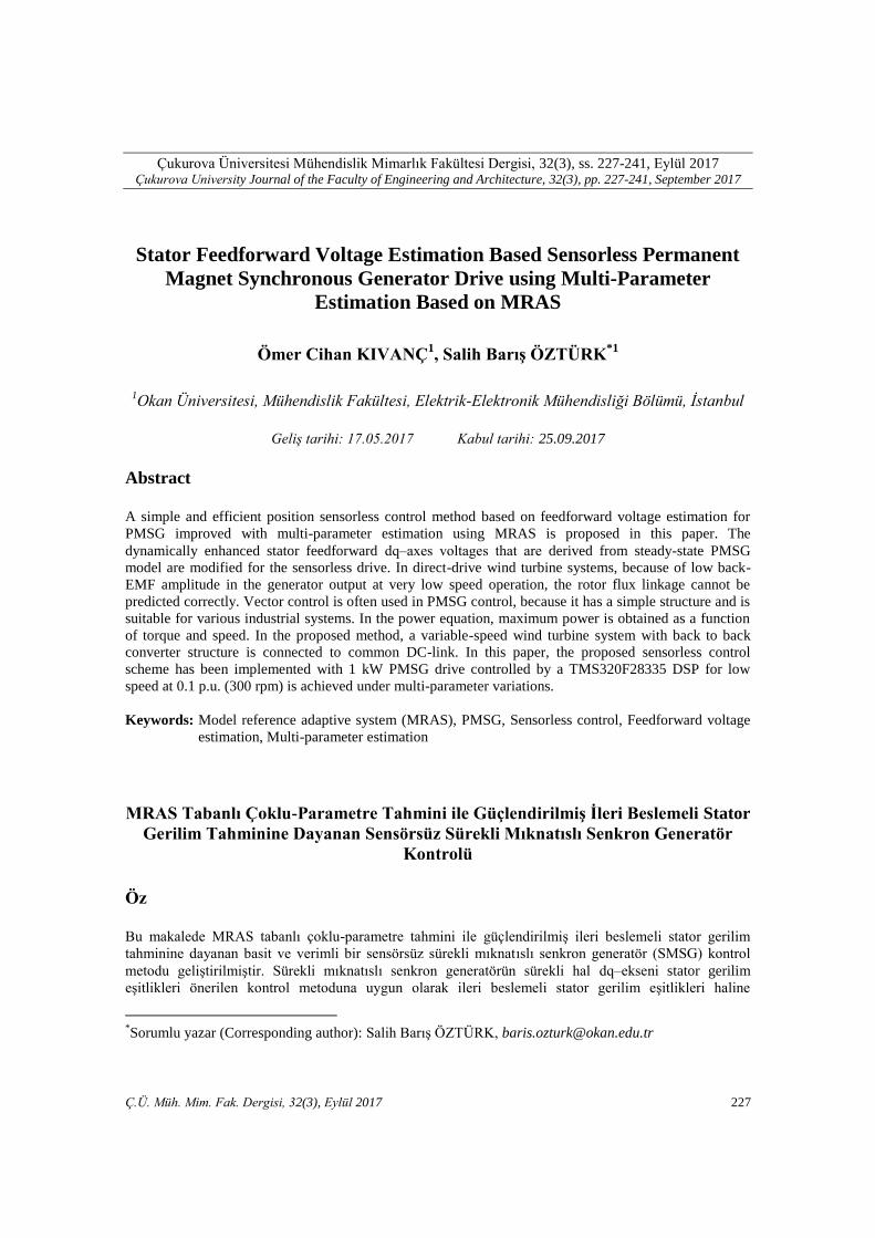
Figure 1. Equivalent electrical circuit diagrams of
quadrate q– and d– axes synchronous
reference frame of PMSG
2. PROPOSED SENSORLESS
CONTROL METHOD AND MPPT
STUDIES
The dq model in the rotating synchronous
reference frame is used to analyze the PMSG for
the proposed speed and position estimations, as
shown in Figure 1. The stator voltage equations of
the PMSG in the rotating dq reference frame are
given by Eq. (1) and Eq. (2), omitting the
influences of magnetic field saturation and
magnetic hysteresis as
vq iqRs+ q
diq
dt+( e did+ e f) (1)
vd idRs+ d
did
dt- e qiq
(2)
where vd, vq, id, iq are the stator d– and q–axes
voltages and currents in the rotor reference frame,
respectively; Rs is the stator winding resistance; d
and q denote the d– and q–axes inductance,
respectively; e is the rotor angular electrical
velocity; and f is the flux linkage due to the
permanent magnet rotor flux [35, 36]. The steady-
state form of dq–axes stator voltage equations can
be derived from Eq. (3) and Eq. (4) by making
derivative terms equal to zero in each equation as
vq iqRs+( e did+ e f)
(3)
vd idRs- e qiq
(4)
–axis circuit –axis circuit
Stator Feedforward Voltage Estimation Based Sensorless Permanent Magnet Synchronous Generator Drive using
Multi-parameter Estimation Based on MRA
230 Ç.Ü. Müh. Mim. Fak. Dergisi, 32(3), Eylül 2017
2.1. Wind Turbine Characteristics and MPPT
Algorithm Based on Indirect Speed
Control
The energy produced in wind turbine systems is
not only based on the turbine characteristics, but
also based on the control method. Output
mechanical power of wind turbine is shown as
Ptur PwindCp 1
2 r2vw
3 Cp( , ) (5)
where is the air density, r is the radius of wind
turbine rotor plane, r2 is the area swept by the
blades, vw is the wind speed, Cp is the turbine
power coefficient, is the tip-speed ratio, and is
the pitch angle. In small wind turbines, fixed pitch
angle is used because of cost and restrictions.
Thus, in Eq. (4), 0 is assumed. The aerodynamic
model of a wind turbine can be characterized by
the well-known Cp( , ) curves. is defined by
Tip Speed
Wind Speed er
vw (6)
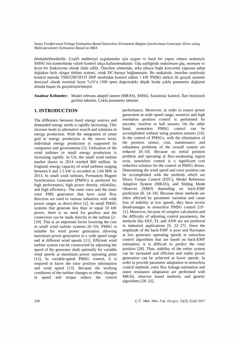
Considering the relationship between and Cp as
the speed changes for a given wind velocity, there
is a unique turbine speed which gives the
maximum output power. The peak power for each
wind speeds occurs at the point where Cp is
maximum. In order to maximize the generated
power, it is desirable for the generator to have a
power characteristic that follows the maximum Cp
curve [18]. Cp is the sixth order polynomial of the
tip-speed ratio. Cp curve is modeled based on the
sixth order polynomial expression [16]. Curve
fitting is a good approximation for wide wind
speed values between 2 m/s and 15 m/s. The
results of the Cp vs. tip speed ratio simulation is
shown in Figure 2.
Cp( ) (c0+∑ ci i
i 6
i 1
) (7)
Cp( ) c1 (c2
i-c3 -c4) e
-c5 i +c6 i (8)
The Cp( ) curves expressed in Eq. (7) and Eq. (8)
depend on the blade design and are given by the
wind turbine characteristic [13].
Figure 2. Power coefficient and tip speed ratio
curve
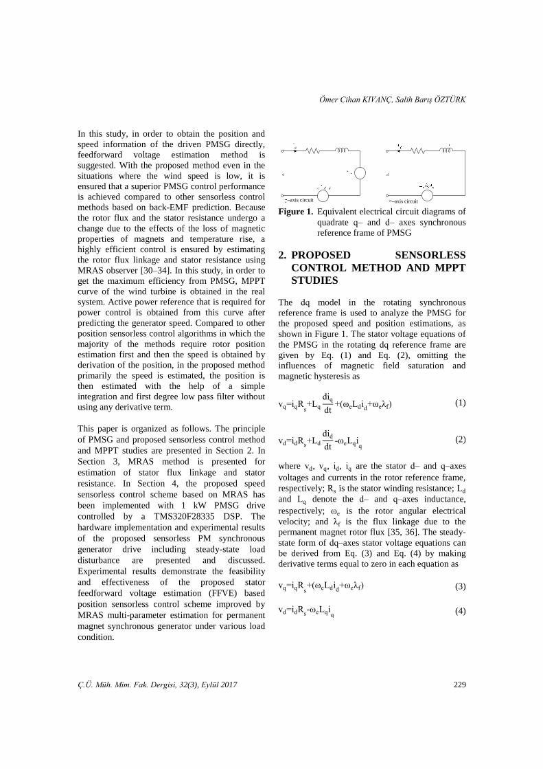
The purpose of the proposed sensorless MPPT
algorithms is to control the shaft speed of the
PMSG to maintain the optimal tip-speed ratio
without the knowledge of the PMSG rotor speed
and wind speed. In the literature, researchers
recommended various methods for sensorless
control of PMSG with MPPT control. Optimal
torque control, perturbation and observation
control, fuzzy logic control and some genetic
algorithms are certain methods.
In this study, torque reference is provided by
reference speed command called indirect speed
control with MPPT [37].
Figure 3. Block diagram of MPPT control
algorithm
Tip Speed Ratio [1.34 unit/div]
Pow
er C
oef
fici
ent
[0.1
25
un
it/d
iv]
Wind Turbine Model
MPPT Model
𝜌𝜋
𝜔
𝜔
𝑣
𝜋𝜌 𝜔
2
𝜔
𝜔
Ömer Cihan KIVANÇ, Salih Barış ÖZTÜRK
Ç.Ü. Müh. Mim. Fak. Dergisi, 32(3), Eylül 2017 231
The prediction of wind speed and rotor speed are
important parameters for maximum power output.
To obtain maximum active power for variable
wind speed, opt can be calculated from the roots
of the derivative of the polynomial in Eq. (8).
Then, based on the reference wind speed vw the
corresponding optimal generator speed is obtained.
Figure 2 shows that the proposed MPPT algorithm
is based on the reference wind turbine. The
equation Eq. (9) shows torque calculation based on
Pwind and Cp.
Te 3p
2 fiq
PwindCp
e
(9)
Reference current is generated from the outer
voltage loop via regulating the DC-link voltage
based on control error. In both voltage control
loops, the PI feedback controllers are enhanced
simply by robust control scheme, as shown in
Figure 3 to yield good dynamic performance.
Reference current is generated based on the
specific wind speed with MPPT mechanism. In
order to produce maximum DC-power in DC-link
at variable speeds, proposed sensorless control
method that is capable of obtaining precise
position estimation at different wind speeds is
proposed.
Teopt R5 e
2Cpopt
2 opt3
(10)
iq* 2Teopt
3p f Cpopt
R5 e2
3p f opt3
(11)
The equations Eq. (10) and Eq. (11) show optimal
torque and optimal q–axis current command that
are given as reference variable wind speed.
dq–axes stator feedforward voltages are normally
used in the FOC of AC machines at the output of
the inner dq–axes PI current regulators to
enhanced the dynamic performance of the machine
[38]. In this method, feedforward voltages are not
only used for the dynamic performance
improvements, but also used to achieve a simple
but effective position sensorless speed control of
PMSG drive.
It is visible that stator d– and q–axes currents can
be controlled by the d– and q–axes voltages and
speed using Eq. (12) and Eq. (13). The control
principle is adopted where the current in q–axis is
controlled by speed of rotation or frequency of
stator voltage applied to q–axis winding [19]. The
amplitude of q–axis voltage is obtained by
neglecting the derivative term and assuming that
real currents closely follow reference values iq iq*
and id id* (reference values are marked with * in
the superscript and hat ^ above is the symbol
indicates estimates) [38]. Below are the modified
stator feedforward voltage equations for the
proposed speed sensorless scheme given in d
reference frame,
vq* iq
*Rs+( e did
*+ e f)+K v (12)
vd* id
*Rs- e qiq
*+ v (13)
where v is the output of the d–axis PI current
regulator and e is the output of the q–axis PI
current regulator. v is multiplied by gain K and
added to q–axis voltage equation vq* representing
the part of the derivative term in the dynamic
voltage equation given in (1). Similarly, v term in
Eq. (12) also acts as the derivative representation
given in Eq. (2) for achieving a better transient
response in the sensorless operation.
The d frame stator voltages given in Eq. (12) and
Eq. (13) are obtained by modifying the dynamic
machine model and used as the basic reference
signals to control the PM machine without
requiring a position sensor. The signals depend on
machine parameters. At any operating point, the
machine itself determines the required voltages at
its terminal by letting the inverter duplicate the
voltages. This process is so called as self-control.
The components of the d frame voltage reference
signals given in Eq. (12) and Eq. (13) are derived
from Eq. (1) and Eq. (2), respectively under the
assumption of steady-state conditions where
Stator Feedforward Voltage Estimation Based Sensorless Permanent Magnet Synchronous Generator Drive using
Multi-parameter Estimation Based on MRA
232 Ç.Ü. Müh. Mim. Fak. Dergisi, 32(3), Eylül 2017
derivative terms are replaced with the regulator
correction terms and a relevant gain.
In stator voltage estimation, stator resistance is
arranged depending on the error between reference
d–axis current and feedback d–axis current
component. Since the stator resistance variation
has a minimal effect on the control, the method
provides high dynamic control capability.
Moreover, q–axis current is controlled by speed
feedback. The method proposed by Okuyama et al.
[39] has been applied for induction machine. The
variation of the rotor flux linkage is estimated by
observer and updated online. According to the
proposed method based on stator voltage
estimation, the voltage signal is added to vq as a
feedforward signal. In this study, a high
performance sensorless operation is performed in a
wide speed range without using high-frequency
signal injection. In speed estimation, v is taken as
the reference which varies proportional to speed.
In the proposed method, while the stator resistance
change effects are not taken into consideration
continuously, the rotor flux linkage variation
determines the performance of the proposed
control method [33, 40]. The rotor flux linkage is
controlled by an additional feedforward voltage
signal. K value is a gain which is determined based
on the variable speed region. Start-up performance
of the generator relies on K value that should be
fixed properly as an important parameter in the
proposed sensorless control.
Note that estimation of rotor speed r is obtained
by passing e obtained from output of the PI
current regulator in q–axis through a first order
filter. The time constant of the filter depends on
the overall system mechanical characteristics and
heavily affects the dynamics and stability of the
sensorless control scheme.
3. ROTOR FLUX LINKAGE AND
STATOR RESISTANCE
ESTIMATOR BASED ON MRAS PMSG motor parameters vary depending on
temperature, frequency, load conditions and work
zone [41, 42]. In order to eliminate the effects of
parameter changes, an MRAS observer structure is
suggested for the proposed sensorless control
scheme. While the rotor position errors occur from
stator resistance change at low speeds, this
problem is eliminated with multi-parameter
estimation; the effects of the rotor flux linkage
change caused from permanent magnets are also
eliminated [43–45].
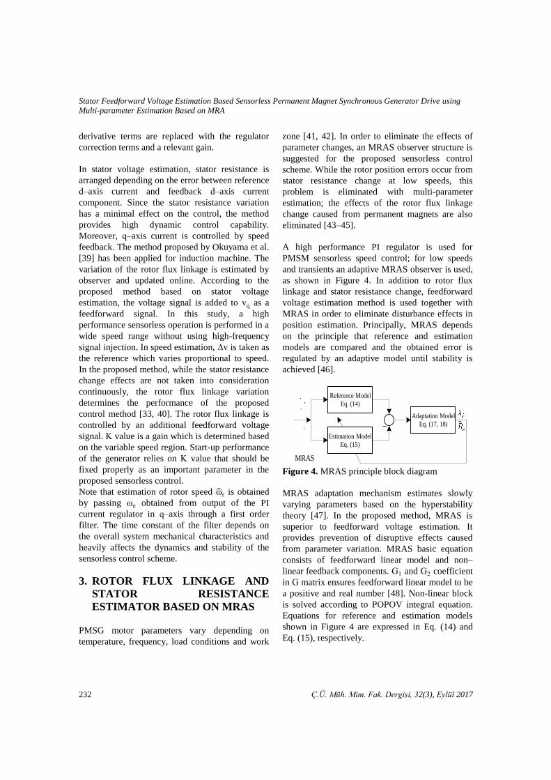
A high performance PI regulator is used for
PMSM sensorless speed control; for low speeds
and transients an adaptive MRAS observer is used,
as shown in Figure 4. In addition to rotor flux
linkage and stator resistance change, feedforward
voltage estimation method is used together with
MRAS in order to eliminate disturbance effects in
position estimation. Principally, MRAS depends
on the principle that reference and estimation
models are compared and the obtained error is
regulated by an adaptive model until stability is
achieved [46].
Figure 4. MRAS principle block diagram
MRAS adaptation mechanism estimates slowly
varying parameters based on the hyperstability
theory [47]. In the proposed method, MRAS is
superior to feedforward voltage estimation. It
provides prevention of disruptive effects caused
from parameter variation. MRAS basic equation
consists of feedforward linear model and non–
linear feedback components. G1 and G2 coefficient
in G matrix ensures feedforward linear model to be
a positive and real number [48]. Non-linear block
is solved according to POPOV integral equation.
Equations for reference and estimation models
shown in Figure 4 are expressed in Eq. (14) and
Eq. (15), respectively.
−
Reference Model
Eq. (14)
Estimation Model
Eq. (15)
Adaptation Model
Eq. (17, 18)
MRAS
Ömer Cihan KIVANÇ, Salih Barış ÖZTÜRK
Ç.Ü. Müh. Mim. Fak. Dergisi, 32(3), Eylül 2017 233
[
diq
dtdid
dt
]
[ -Rs
q
- d
q
e
q
d
e
-Rs
d ]
⏟ A
[iq
id]
+
[ 1
q
0
01
d]
⏟ B
[vqvd] + *
- f
q
e
0
+
⏟ C
(14)
[ diq
dt
did
dt ]
[ -Rs
q
- d
q
e
q
d
e
-Rs
d ]
⏟ A
*iq
id+
+
[ 1
q
0
01
d]
⏟ B
[vqvd]+ *
- f
q
e
0
+
⏟ C
+ [G1 0
0 G2]
⏟ G
*iq-iq
id-id+
(15)
where Rs and f are the estimated stator resistance
and rotor flux linkage, respectively which are the
outputs of the adaptation model. Rs and f are
updated in the estimation block in the closed loop
system, as a result iq and id currents are predicted.
e
[ d(iq-iq)
dt
d(id-id)
dt ]
(
[ -Rs
q
- d
q
e
q
d
e
-Rs
d ]
+ [G1 0
0 G2]
)
*iq-iq
id-id+
+
(
[ -Rs
q
- d
q
e
q
d
e
-Rs
d ]
-
[ -Rs
q
- d
q
e
q
d
e
-Rs
d ]
)
*iq
id+
+(*
- f
q
e
0
+ - *- f
q
e
0
+)
(16)
In Eq. (16), the errors of the MRAS current
estimators are given. Selection of accurate values
of G1 and G2 gains given in Eq. (15) eliminate the
algebraic loop problem occurs in simulation and
experimental studies [48]. The error correction is
accomplished by an adaptation model. G matrix
given in Eq. (15) is an observer gain matrix in
which the parameters should be adjusted properly
[46]. False selection of the G matrix parameters
causes algebraic loops. Adaptation equations for
Rs and f are given in Eq. (17) and Eq. (18),
respectively where kpres, kires , kpflux
, kiflux, R0, f0
are the estimated resistance proportional regulator
coefficient, estimated resistance integrator
regulator coefficient, estimated rotor flux linkage
proportional regulator coefficient, rotor flux
linkage integrator regulator coefficient, and the
estimated previous stator resistance and rotor flux
linkage, respectively.
Rs -(kpres+kiress
)( s
id(id-id)+iq(iq-iq))+ R0
(17)
f - (kpflux+kifluxs) e(iq-iq) s+ f0. (18)
Stator resistance and rotor flux linkage estimation
values in Eq. (17) and Eq. (18) guarantees to give
faster response than the closed loop cycle. Since
large selected state errors are constantly growing
and small selected estimation time gets longer,
selection of proper regulator parameters are crucial
for minimizing the steady-state error [49]. In the
proposed MRAS method, a low-pass filter (LPF) is
used to overcome the rise of the estimated rotor
flux linkage value at low speed and at zero
crossing and distortion effects caused from stator
resistance estimation. In the situations where LPF
is not used at low speed, the estimation values are
small and cause the output of the feedforward
voltage estimation values to be faulty [50].
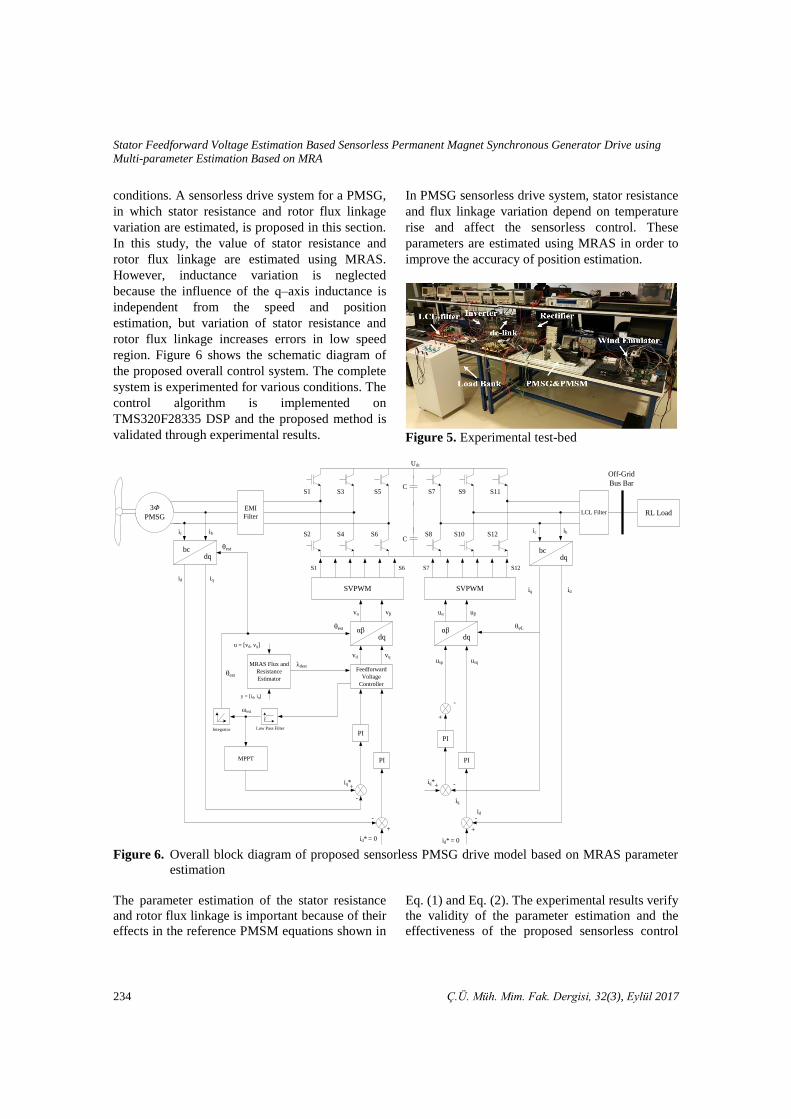
4. EXPERIMENTAL RESULTS
To show validity of the proposed control scheme,
the experimental studies are carried out for the
systems shown in Figure 5 under various operation
Stator Feedforward Voltage Estimation Based Sensorless Permanent Magnet Synchronous Generator Drive using
Multi-parameter Estimation Based on MRA
234 Ç.Ü. Müh. Mim. Fak. Dergisi, 32(3), Eylül 2017
conditions. A sensorless drive system for a PMSG,
in which stator resistance and rotor flux linkage
variation are estimated, is proposed in this section.
In this study, the value of stator resistance and
rotor flux linkage are estimated using MRAS.
However, inductance variation is neglected
because the influence of the q–axis inductance is
independent from the speed and position
estimation, but variation of stator resistance and
rotor flux linkage increases errors in low speed
region. Figure 6 shows the schematic diagram of
the proposed overall control system. The complete
system is experimented for various conditions. The
control algorithm is implemented on
TMS320F28335 DSP and the proposed method is
validated through experimental results.
In PMSG sensorless drive system, stator resistance
and flux linkage variation depend on temperature
rise and affect the sensorless control. These
parameters are estimated using MRAS in order to
improve the accuracy of position estimation.
Figure 5. Experimental test-bed
Figure 6. Overall block diagram of proposed sensorless PMSG drive model based on MRAS parameter
estimation
The parameter estimation of the stator resistance
and rotor flux linkage is important because of their
effects in the reference PMSM equations shown in
Eq. (1) and Eq. (2). The experimental results verify
the validity of the parameter estimation and the
effectiveness of the proposed sensorless control
C
C
SVPWM
S3
S4
S5
S6
S7
S8
3Φ
PMSG
bcdq
LCL FilterEMI
Filter
id
α dq
Feedforward
Voltage
Controller
MRAS Flux and
Resistance
Estimator
PI
iq
ic ib
MPPT
Low Pass FilterIntegrator
y = [id, iq]
u = [vd, vq]
θest
vα v
PI
+
+
-
-
id* = 0
est
vd vq
θest
dest
α dq
PI
PI
+
+
-
-
Udc
ic ib
uα u
S1
usp usq
θѱL
+
-
θest
Off-Grid
Bus Bar
RL Load
iq*
id* = 0
iq*
bcdq
idiq
id
iq
S9
S10
S6
S1
S2
S11
S12
SVPWM
S7 S12
Ömer Cihan KIVANÇ, Salih Barış ÖZTÜRK
Ç.Ü. Müh. Mim. Fak. Dergisi, 32(3), Eylül 2017 235
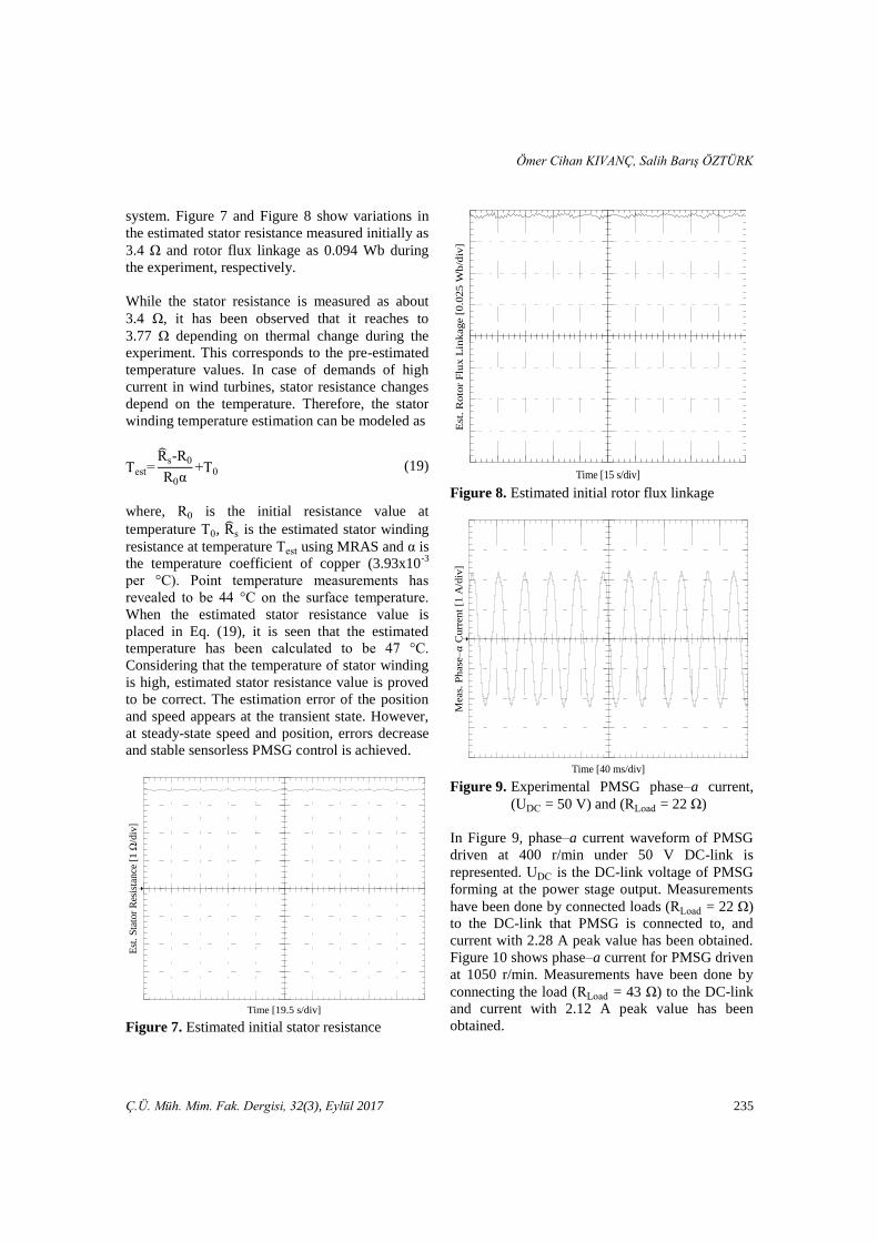
system. Figure 7 and Figure 8 show variations in
the estimated stator resistance measured initially as
3.4 and rotor flux linkage as 0.094 Wb during
the experiment, respectively.
While the stator resistance is measured as about
3.4 , it has been observed that it reaches to
3.77 depending on thermal change during the
experiment. This corresponds to the pre-estimated
temperature values. In case of demands of high
current in wind turbines, stator resistance changes
depend on the temperature. Therefore, the stator
winding temperature estimation can be modeled as
Test Rs-R0
R0α+T0 (19)
where, R0 is the initial resistance value at
temperature T0, Rs is the estimated stator winding
resistance at temperature Test using MRAS and α is
the temperature coefficient of copper (3.93x10⁻³
per °C). Point temperature measurements has
revealed to be 44 °C on the surface temperature.
When the estimated stator resistance value is
placed in Eq. (19), it is seen that the estimated
temperature has been calculated to be 47 °C.
Considering that the temperature of stator winding
is high, estimated stator resistance value is proved
to be correct. The estimation error of the position
and speed appears at the transient state. However,
at steady-state speed and position, errors decrease
and stable sensorless PMSG control is achieved.
Figure 7. Estimated initial stator resistance
Figure 8. Estimated initial rotor flux linkage
Figure 9. Experimental PMSG phase–a current,
(UDC = 50 V) and (R oad = 22 )
In Figure 9, phase–a current waveform of PMSG
driven at 400 r/min under 50 V DC-link is
represented. UDC is the DC-link voltage of PMSG
forming at the power stage output. Measurements
have been done by connected loads (R oad = 22 )
to the DC-link that PMSG is connected to, and
current with 2.28 A peak value has been obtained.
Figure 10 shows phase–a current for PMSG driven
at 1050 r/min. Measurements have been done by
connecting the load (R oad = 43 ) to the DC-link
and current with 2.12 A peak value has been
obtained.
Est
. S
tato
r R
esis
tance
[1
/div
]
Time [19.5 s/div]
Est
. R
oto
r F
lux L
inkage [
0.0
25 W
b/d
iv]
Time [15 s/div]
Time [40 ms/div]
Meas.
Ph
ase–𝑎
Cu
rren
t [1
A/d
iv]
Stator Feedforward Voltage Estimation Based Sensorless Permanent Magnet Synchronous Generator Drive using
Multi-parameter Estimation Based on MRA
236 Ç.Ü. Müh. Mim. Fak. Dergisi, 32(3), Eylül 2017
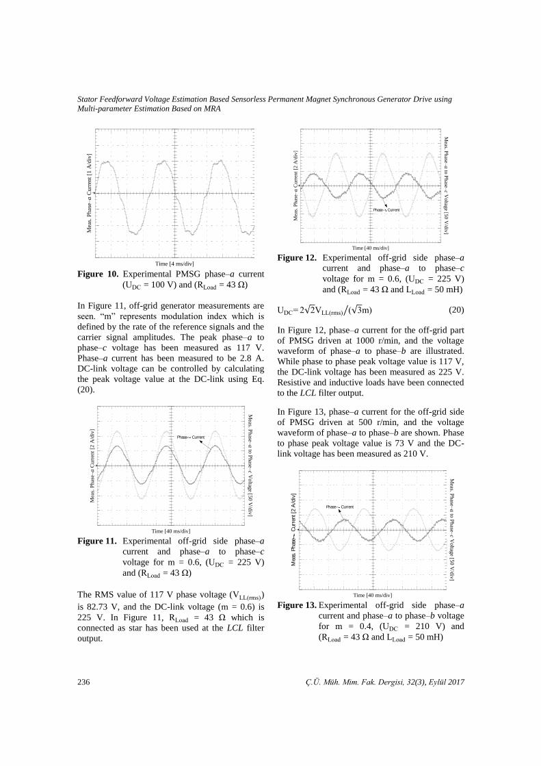
Figure 10. Experimental PMSG phase–a current
(UDC = 100 V) and (R oad = 43 )
In Figure 11, off-grid generator measurements are
seen. “m” represents modulation index which is
defined by the rate of the reference signals and the
carrier signal amplitudes. The peak phase–a to
phase–c voltage has been measured as 117 V.
Phase–a current has been measured to be 2.8 A.
DC-link voltage can be controlled by calculating
the peak voltage value at the DC-link using Eq.
(20).
Figure 11. Experimental off-grid side phase–a
current and phase–a to phase–c
voltage for m = 0.6, (UDC = 225 V)
and (R oad = 43 )
The RMS value of 117 V phase voltage (V (rms))
is 82.73 V, and the DC-link voltage (m = 0.6) is
225 V. In Figure 11, R oad = 43 which is
connected as star has been used at the LCL filter
output.
Figure 12. Experimental off-grid side phase–a
current and phase–a to phase–c
voltage for m = 0.6, (UDC = 225 V)
and (R oad = 43 and oad = 50 mH)
UDC 2√2V (rms) (√3m)⁄ (20)
In Figure 12, phase–a current for the off-grid part
of PMSG driven at 1000 r/min, and the voltage
waveform of phase–a to phase–b are illustrated.
While phase to phase peak voltage value is 117 V,
the DC-link voltage has been measured as 225 V.
Resistive and inductive loads have been connected
to the LCL filter output.
In Figure 13, phase–a current for the off-grid side
of PMSG driven at 500 r/min, and the voltage
waveform of phase–a to phase–b are shown. Phase
to phase peak voltage value is 73 V and the DC-
link voltage has been measured as 210 V.
Figure 13. Experimental off-grid side phase–a
current and phase–a to phase–b voltage
for m = 0.4, (UDC = 210 V) and
(R oad = 43 and oad = 50 mH)
Mea
s. P
has
e–𝑎
Curr
ent
[1 A
/div
]
Time [4 ms/div]
Time [40 ms/div]
Meas. P
hase–
𝑎 to
Phase–
𝑐 V
oltag
e [50
V/d
iv]
Phase– Current
Mea
s. P
has
e–𝑎
Curr
ent
[2 A
/div
]
Meas. P
hase–
𝑎 to
Ph
ase–𝑐 V
oltag
e [50
V/d
iv]
Time [40 ms/div]
Phase– Current
Mea
s. P
has
e–𝑎
Cu
rren
t [2
A/d
iv]
Mea
s. P
has
e– C
urr
ent [2
A/d
iv]
Time [40 ms/div]
Phase– Current
Meas. P
hase–
𝑎 to
Ph
ase–𝑐 V
oltag
e [50
V/d
iv]
Ömer Cihan KIVANÇ, Salih Barış ÖZTÜRK
Ç.Ü. Müh. Mim. Fak. Dergisi, 32(3), Eylül 2017 237
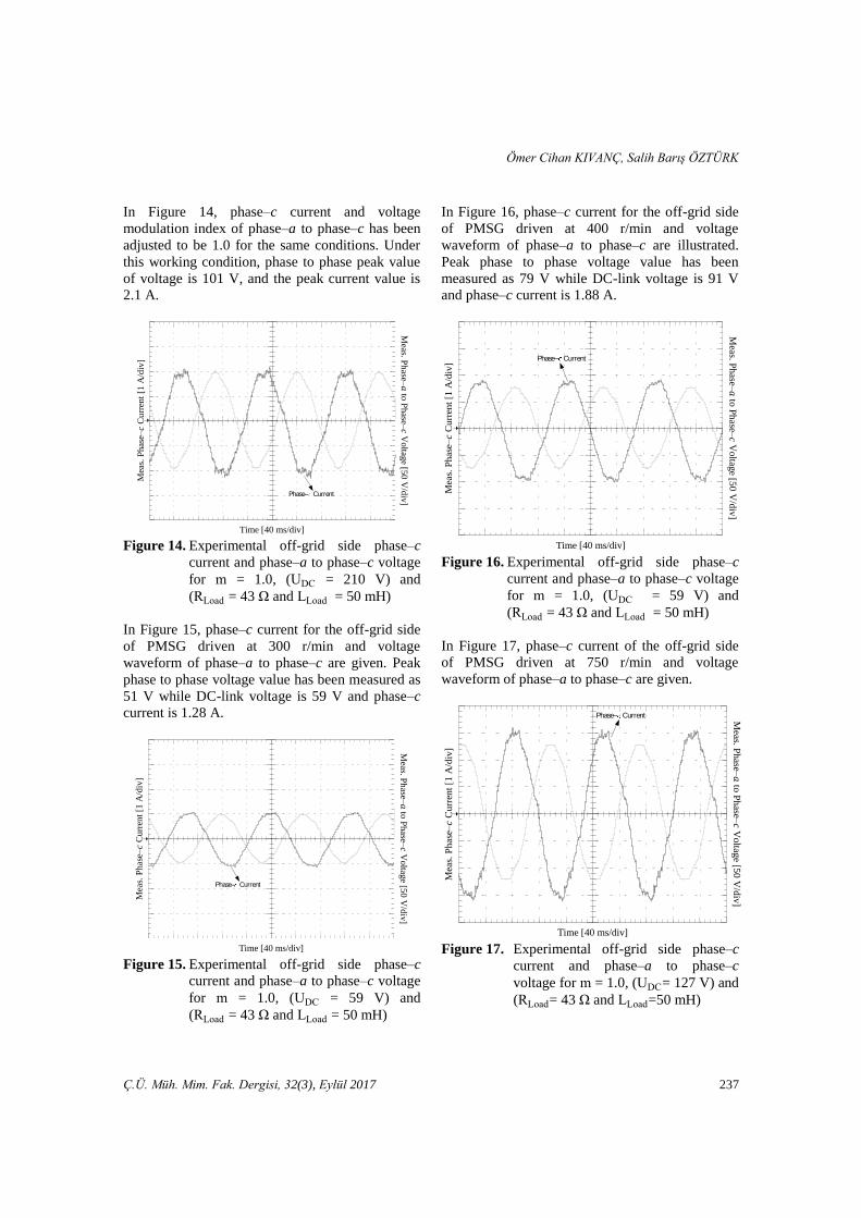
In Figure 14, phase–c current and voltage
modulation index of phase–a to phase–c has been
adjusted to be 1.0 for the same conditions. Under
this working condition, phase to phase peak value
of voltage is 101 V, and the peak current value is
2.1 A.
Figure 14. Experimental off-grid side phase–c
current and phase–a to phase–c voltage
for m = 1.0, (UDC = 210 V) and
(R oad = 43 and oad = 50 mH)
In Figure 15, phase–c current for the off-grid side
of PMSG driven at 300 r/min and voltage
waveform of phase–a to phase–c are given. Peak
phase to phase voltage value has been measured as
51 V while DC-link voltage is 59 V and phase–c
current is 1.28 A.
Figure 15. Experimental off-grid side phase–c
current and phase–a to phase–c voltage
for m = 1.0, (UDC = 59 V) and
(R oad = 43 and oad = 50 mH)
In Figure 16, phase–c current for the off-grid side
of PMSG driven at 400 r/min and voltage
waveform of phase–a to phase–c are illustrated.
Peak phase to phase voltage value has been
measured as 79 V while DC-link voltage is 91 V
and phase–c current is 1.88 A.
Figure 16. Experimental off-grid side phase–c
current and phase–a to phase–c voltage
for m = 1.0, (UDC = 59 V) and
(R oad = 43 and oad = 50 mH)
In Figure 17, phase–c current of the off-grid side
of PMSG driven at 750 r/min and voltage
waveform of phase–a to phase–c are given.
Figure 17. Experimental off-grid side phase–c
current and phase–a to phase–c
voltage for m = 1.0, (UDC= 127 V) and
(R oad= 43 and oad=50 mH)
Time [40 ms/div]
Meas. P
hase–
𝑎 to
Phase–
𝑐 V
oltag
e [50
V/d
iv]
Phase– Current
Mea
s. P
has
e–𝑐
Curr
ent
[1 A
/div
]
Phase– Current
Mea
s. P
has
e–𝑐
Curr
ent
[1 A
/div
]
Time [40 ms/div]
Meas. P
hase–
𝑎 to
Phase–
𝑐 V
oltag
e [50
V/d
iv]
Meas. P
hase–
𝑎 to
Phase–
𝑐 V
oltag
e [50
V/d
iv]
Time [40 ms/div]
Mea
s. P
has
e–𝑐
Curr
ent
[1 A
/div
]
Phase– Current
Time [40 ms/div]
Mea
s. P
has
e–𝑐
Curr
ent
[1 A
/div
]
Meas. P
hase–
𝑎 to
Phase–
𝑐 V
oltag
e [50
V/d
iv]
Phase– Current
Stator Feedforward Voltage Estimation Based Sensorless Permanent Magnet Synchronous Generator Drive using
Multi-parameter Estimation Based on MRA
238 Ç.Ü. Müh. Mim. Fak. Dergisi, 32(3), Eylül 2017
Peak voltage value between phase–a to phase–c
has been measured as 127 V while DC-link
voltage is 147 V and phase–c current is 3.24 A.
Measurements reflect that THD of the voltage
between phase–a to phase–b at the LCL-filter input
in the off-grid side of SSTP (assuming there is no
LCL filter) is 51.15% and it is considered too high.
The THD of the voltage phase–a to phase–b at the
LCL filter output in the off-grid side of SSTP is
around 4%.
4. CONCLUSION
The rotor flux linkage that changes due to aging,
vibration, humidity and temperature reduces the
drive control performance. So, the effects of aging
are tried to be eliminated and the control
performance is increased with life estimation
algorithms in the literature using online-learning
methods and parameter estimation methods.
Because the rotor flux and the stator resistance
undergo a change due to the effects of the loss of
magnetic properties of magnets and temperature
rise, a highly efficient control is ensured by
estimating the rotor flux linkage and stator
resistance using MRAS observer. In order to
obtain the position and speed information of the
driven PMSG directly, feedforward voltage
estimation method is suggested. With the proposed
method even in the situations where the wind
speed is low, it is ensured that a superior PMSG
control performance compared to other sensorless
control methods based on back-EMF prediction is
achieved.
Using the proposed method, maximum power
generation with 4% THD in the line voltages is
achieved by using the designed LCL filter
compared to other back-EMF estimation methods
even under low wind speeds at 0.1 p.u. (300 rpm)
of the PMSG drive.
5. ACKNOWLEDGMENTS
This work was supported by The Scientific and
Technological Research Council of Turkey
(TUBITAK) funded project (112E263).
APPENDIX
Parameters of the PM Synchronous Machine
Number of poles : 8
Rated torque (N∙m) : 2
Rated rms current (A) : 4
Stator inductance (mH) : 0.0033
Stator resistance ( ) : 3.4
Rotor magnetic flux linkage (Wb) : 0.095
Moment of inertia (kg.m2) : 0.0075
6. REFERENCES
1. Dasgupta, S., Mohan, S.N., Sahoo, S.K. Panda,
S.K., 2013. Application of Four-Switch-Based
Three-Phase Grid-Connected Inverter to
Connect Renewable Energy Source to a
Generalized Unbalanced Microgrid System.
IEEE Transactions on Industrial Electronics,
60(3), 12041215.
2. Iov, F., Blaabjerg, F., 2009. Power Electronics
and Control for Wind Power Systems, IEEE
Power Electronics and Machines in Wind
Applications, PEMWA, 116.
3. Parviainen, A., Pyrhonen, J., Kontkanen, P.,
2005. Axial Flux Permanent Magnet Generator
with Concentrated Winding for Small Wind
Power Applications, 11871191.
4. Bumby, J.R., Stannard, N., Dominy, J.,
McLeod, N., 2008. A Permanent Magnet
Generator for Small Scale Wind and Water
Turbines, 16.
5. Andriollo, M., De Bortoli, M., Martinelli, G.,
Morini, A., Tortella, A., 2008. Permanent
Magnet Axial Flux Disc Generator for Small
Wind Turbines, 16.
6. Olano, A., Moreno, V., Molina, J., Zubia, I.,
2008. Design and Construction of an Outer-
Rotor PM Synchronous Generator for Small
Wind Turbines; Comparing Real Results with
Those of FE Model, 16.
7. Haraguchi, H., Morimoto, S., Sanada, M.,
2009. Suitable Design of a PMSG for a Small-
Scale Wind Power Generator, 16.
8. Zhang, Z., Zhao, Y., Qiao, W., Qu, L., 2014. A
Space-Vector-Modulated Sensorless Direct-
Torque Control for Direct-Drive PMSG Wind
Ömer Cihan KIVANÇ, Salih Barış ÖZTÜRK
Ç.Ü. Müh. Mim. Fak. Dergisi, 32(3), Eylül 2017 239
Turbines, IEEE Transactions on Industry
Applications, 50(4), 23312341.
9. Benadja, M., Chandra, A., 2014. Sensorless
Control for Wind Energy Conversion System
(WECS) with Power Quality Improvement,
IEEE PES General Meeting| Conference &
Exposition, 15.
10. Hu, K.W., Liaw, C.M., 2015. Position
Sensorless Surface-Mounted Permanent-
Magnet Synchronous Generator and its
Application to Power DC Microgrid. IET
Power Electronics, 8(9), 16361650.
11. Baroudi, J.A., Dinavahi, V., Knight, A.M.,
2007. A Review of Power Converter
Topologies for Wind Generators. Renewable
Energy, 32(14), 23692385.
12. Muller, S., Deicke, M., De Doncker, R.W.,
2002. Doubly Fed Induction Generator
Systems for Wind Turbines. IEEE Industry
Applications Magazine, 8(3), 2633.
13. Qiao, W., Zhou, W., Aller, J.M., Harley, R.G.,
2008. Wind Speed Estimation Based
Sensorless Output Maximization Control for A
Wind Turbine Driving a DFIG. IEEE
Transactions on Power Electronics, 23(3),
11561169.
14. Guo, L., Zhang, X., Yang, S., Xie, Z., Qi, L.,
Wang, L., 2015. Super-Twisting Sliding Mode
Observer Based Speed Sensorless Torque
Control for PMSG Used in Wind Turbines,
24572462.
15. Ding, Z., Wei, G., Ding, X., 2014. PMSM
Control System Based on Sliding Mode
Technology and MRAS Method. IEEE
International Conference on Mechatronics and
Control (ICMC), 12761281.
16. Koch, G., Gabbi, T., Henz, G., Vieira, R.P.,
Pinheiro, H., 2015. Sensorless Technique
Applied to PMSG Of WECS Using Sliding
Mode Observer. IEEE 13th Brazilian Power
Electronics Conference and 1st Southern Power
Electronics Conference (COBEP/SPEC),
16.
17. Han, Y.S., Choi, J.S., Kim, Y.S., 2000.
Sensorless PMSM Drive with a Sliding Mode
Control Based Adaptive Speed and Stator
Resistance Estimator. IEEE Transactions on
Magnetics, 36(5), 35883591.
18. Yan, J., Lin, H., Feng, Y., Guo, X., Huang, Y.,
Zhu, Z.Q., 2013. Improved Sliding Mode
Model Reference Adaptive System Speed
Observer for Fuzzy Control of Direct-Drive
Permanent Magnet Synchronous Generator
Wind Power Generation System. IET
Renewable Power Generation, 7(1), 2835.
19. Akatsu, K., Kawamura, A., 2000. Sensorless
Very Low-Speed and Zero-Speed Estimations
with Online Rotor Resistance Estimation of
Induction Motor Without Signal Injection.
IEEE Transactions on Industry Applications,
36(3), 764771.
20. Eskola, M., Tuusa, H., 2003. Comparison of
MRAS and Novel Simple Method for Position
Estimation in PMSM Drives, vol. 2,
550555.
21. Burth, M., Verghese, G.C., Vélez-Reyes, M.,
1999. Subset Selection for Improved Parameter
Estimation in On-line Identification of a
Synchronous Generator, IEEE Transactions on
Power Systems, 14(1), 218225.
22. Liu, K., Zhu, Z.Q., Stone, D.A., 2013.
Parameter Estimation for Condition Monitoring
of PMSM Stator Winding and Rotor Permanent
Magnets, IEEE Transactions on Industrial
Electronics, 60(12), 59025913.
23. Chan, T.F., Wang, W., Borsje, P., Wong, Y.K.,
Ho, S.L., 2008. Sensorless Permanent-Magnet
Synchronous Motor Drive Using a Reduced-
Order Rotor Flux Observer. IET Electric Power
Applications, 2(2), 8898.
24. Rigatos, G., Siano, P., Zervos, N., 2014.
Sensorless Control of Distributed Power
Generators with the Derivative-free Nonlinear
Kalman Filter, IEEE Transactions on Industrial
Electronics, 61(11), 63696382.
25. Shasadeghi, M., Mardanah, M., Nayeripour,
M., Mansuri, M., 2015. Sensor Less Control of
PMSG-based Wind Turbine with Parallel
Distributed Compensator with Fuzzy Observer,
3540.
26. Benadja, M., Chandra, A., 2015. Adaptive
Sensorless Control of Pmsgs-Based Offshore
Wind Farm and VSC-HVDC Stations, IEEE
Journal of Emerging and Selected Topics in
Power Electronics, 3(4), 918931.
Stator Feedforward Voltage Estimation Based Sensorless Permanent Magnet Synchronous Generator Drive using
Multi-parameter Estimation Based on MRA
240 Ç.Ü. Müh. Mim. Fak. Dergisi, 32(3), Eylül 2017
27. Li, H., Shi, K.L., McLaren, P.G., 2005. Neural-
Network-Based Sensorless Maximum Wind
Energy Capture with Compensated Power
Coefficient. IEEE Transactions on Industry
Applications, 41(6), 15481556.
28. Inoue, Y., Yamada, K., Morimoto, S., Sanada,
M., 2007. Accuracy Improvement of IPMSM
Sensorless Drives with On-line Parameter
Identification, 860866.
29. Colovic, I., Kutija, M., Sumina, D., 2014.
Rotor Flux Estimation for Speed Sensorless
Induction Generator Used in Wind Power
Application, 2327.
30. Liu, K., Zhu, Z.Q., 2014. Online Estimation of
the Rotor Flux Linkage and Voltage-source
Inverter Nonlinearity in Permanent Magnet
Synchronous Machine Drives, IEEE
Transactions on Power Electronics, 29(1),
418427.
31. Lei, T., Barnes, M., Smith, S., Hur, S.H.,
Stock, A., Leithead, W.E., 2015. Using
Improved Power Electronics Modeling and
Turbine Control to Improve Wind Turbine
Reliability. IEEE Transactions on Energy
Conversion, 30(3), 10431051.
32. Jung, S.M., Park, J.S., Kim, H.W., Cho, K.Y.,
Youn, M.J., 2013. An MRAS-Based Diagnosis
of Open-circuit Fault in PWM Voltage-source
Inverters for PM Synchronous Motor Drive
Systems, IEEE Transactions on Power
Electronics, 28(5), 25142526.
33. Xiao, X., Chen, C., Zhang, M., 2010. Dynamic
Permanent Magnet Flux Estimation of
Permanent Magnet Synchronous Machines.
IEEE Transactions on Applied
Superconductivity, 20(3), 10851088.
34. Dumnic, B., Katic, V., Vasic, V., Milicevic, D.,
Delimar, M., 2012. An Improved MRAS Based
Sensorless Vector Control Method for Wind
Power Generator, Journal of Applied Research
and Technology, 10(5), 687697.
35. Bose, B.K., 1997. Power Electronics and
Variable Frequency Drives: Technology and
Applications, 3676.
36. Krishnan, R., 2009. Permanent Magnet
Synchronous and Brushless DC Motor Drives,
CRC Press.
37. Diaz, S.A., Silva, C., Juliet, J., Miranda, H.A.,
2009. Indirect Sensorless Speed Control of a
PMSG for Wind Application, 18441850.
38. Holtz, J., 2002. Sensorless Control of Induction
Motor Drives, Proceedings of the IEEE, 90(8),
13591394.
39. Okuyama, T., Fujimoto, N., Fujii, H., 1990. A
Simplified Vector Control System Without
Speed and Voltage Sensors-effect of Setting
Errors of Control Parameters and Their
Compensation. Electrical Engineering in Japan,
110(4), 129139.
40. Akatsu, K., Kawamura, A., 2000. Online Rotor
Resistance Estimation Using the Transient
State Under the Speed Sensorless Control of
Induction Motor, IEEE Transactions on Power
Electronics, 15(3), 553560.
41. Underwood, S.J., Husain, I., 2010. Online
Parameter Estimation and Adaptive Control of
Permanent-magnet Synchronous Machines,
IEEE Transactions on Industrial Electronics,
57(7), 24352443.
42. Bolognani, S., Peretti, L., Zigliotto, M., 2008.
Parameter Sensitivity Analysis of an Improved
Open-Loop Speed Estimate for Induction
Motor Drives. IEEE Transactions on Power
Electronics, 23(4), 21272135.
43. Ozturk, S.B., Akin, B., Toliyat, H.A.,
Ashrafzadeh, F., 2006. Low-cost Direct Torque
Control of Permanent Magnet Synchronous
Motor Using Hall-effect Sensors, 714.
44. Lu, Z., Sheng, H., Hess, H.L., Buck, K.M.,
2005. The Modeling and Simulation of a
Permanent Magnet Synchronous Motor with
Direct Torque Control Based on
Matlab/simulink, IEEE International
Conference on Electric Machines and Drives,
7.
45. Seok, J.K., Lee, J.K., Lee, D.C., 2006.
Sensorless Speed Control of Nonsalient
Permanent-magnet Synchronous Motor Using
Rotor-position-tracking PI Controller, IEEE
Transactions on Industrial Electronics, 53(2),
399405.
46. Stumberger, B., Stumberger, G., Dolinar, D.,
Hamler, A., Trlep, M., 2003. Evaluation of
Saturation and Cross-magnetization Effects in
Interior Permanent-magnet Synchronous
Ömer Cihan KIVANÇ, Salih Barış ÖZTÜRK
Ç.Ü. Müh. Mim. Fak. Dergisi, 32(3), Eylül 2017 241
Motor, IEEE Transactions on Industry
Applications, 39(5), 12641271.
47. Rusu, C., Radulescu, M.M., Enikö, S.,
Melinda, R.K., Jakab, Z.L., 2014. Embedded
Motor Drive Prototype Platform for Testing
Control Algorithms, International Conference
on Applied and Theoretical Electricity
(ICATE), 16.
48. Marcetic, D.P., Vukosavic, S.N., 2007. Speed-
sensorless AC Drives with the Rotor Time
Constant Parameter Update, IEEE Transactions
on Industrial Electronics, 54(5), 26182625.
49. Mouna, B.H., Lassaad, S., 2006. Speed
Sensorless Indirect Stator Field Oriented
Control of Induction Motor Based on
Luenberger Observer, IEEE International
Symposium on Industrial Electronics, vol. 3,
24732478.
50. Shi, Y., Sun, K., Huang, L., Li, Y., 2012.
Online Identification of Permanent Magnet
Flux Based on Extended Kalman Filter for
IPMSM Drive with Position Sensorless
Control, IEEE Transactions on Industrial
Electronics, 59(11), 41694178.

Stator Feedforward Voltage Estimation Based Sensorless Permanent Magnet Synchronous Generator Drive using
Multi-parameter Estimation Based on MRA
242 Ç.Ü. Müh. Mim. Fak. Dergisi, 32(3), Eylül 2017