Embed Size (px)
Citation preview
ANL-‐ARC-‐186
Status Report on Improved Understanding of Creep-fatigue Damage in Advanced Materials
Nuclear Engineering Division
Availability of This ReportThis report is available, at no cost, at http://www.osti.gov/bridge. It is also available on paper to the U.S. Department of Energy and its contractors, for a processing fee, from:
U.S. Department of Energy
OfficeofScientificandTechnicalInformation
P.O. Box 62
Oak Ridge, TN 37831-0062
phone (865) 576-8401
fax (865) 576-5728
Disclaimer
This report was prepared as an account of work sponsored by an agency of the United States Government. Neither the United States
Governmentnoranyagencythereof,norUChicagoArgonne,LLC,noranyoftheiremployeesorofficers,makesanywarranty,express
or implied, or assumes any legal liability or responsibility for the accuracy, completeness, or usefulness of any information, apparatus,
product,orprocessdisclosed,orrepresentsthatitsusewouldnotinfringeprivatelyownedrights.Referencehereintoanyspecific
commercial product, process, or service by trade name, trademark, manufacturer, or otherwise, does not necessarily constitute or imply
its endorsement, recommendation, or favoring by the United States Government or any agency thereof. The views and opinions of
documentauthorsexpressedhereindonotnecessarilystateorreflectthoseoftheUnitedStatesGovernmentoranyagencythereof,
Argonne National Laboratory, or UChicago Argonne, LLC.
About Argonne National Laboratory Argonne is a U.S. Department of Energy laboratory managed by UChicago Argonne, LLC under contract DE-AC02-06CH11357. The Laboratory’s main facility is outside Chicago, at 9700 South Cass Avenue, Argonne, Illinois 60439. For information about Argonne, see www.anl.gov.
ANL-‐ARC-‐186
Status Report on Improved Understanding of Creep-‐fatigue Damage in Advanced Materials
Meimei Li, Saurin Majumdar, William K. Soppet, David Rink, and Ken Natesan Nuclear Engineering Division Argonne National Laboratory May 2011

Status Report on Improved Understanding of Creep-‐fatigue Damage in Advanced Materials May 2011
Status Report on Improved Understanding of Creep-‐fatigue Damage in Advanced Materials May 2011
ANL-‐ARC-‐186
i
ABSTRACT
This report provides an update on the materials performance criteria and methodology relevant to liquid metal reactors (LMRs), in particular, sodium cooled fast reactors. The report is the first deliverable (Level 3) in FY11 (M3A11AN04030303) under the work package A-11AN040303 “Materials Performance Criteria and Methodology” as part of Advanced Structural Materials Program for the Advanced Reactor Concepts.
The overall objective of the Advanced Materials Performance Criteria and Methodology project is to evaluate the key requirements for the ASME Code qualification and the Nuclear Regulatory Commission (NRC) approval of advanced structural materials in support of the design and licensing of the liquid metal fast reactors. Advanced materials are a critical element in the development of fast reactor technologies. Enhanced materials performance not only improves safety margins and provides design flexibility but also is essential for the economics of future advanced fast reactors. Qualification and licensing of advanced materials are prominent needs for the development and implementation of advanced fast reactor technologies. Nuclear structural component designs in the U.S. comply with the ASME Boiler and Pressure Vessel (B&PV) Code Section III (Rules for Construction of Nuclear Facility Components) and the NRC grants licensing. As the LMR will operate at higher temperatures than the current light water reactors (LWRs), the design of elevated-temperature components must comply with ASME Section III Subsection NH (Class 1 Components in Elevated Temperature Service). A number of technical issues relevant to materials performance criteria and high temperature design methodology in the LMR were identified and presented in earlier reports [Natesan et al. 2008, 2009]. A viable approach to resolve these issues and the R&D priority were also recommended. The development of mechanistically based creep-fatigue interaction models for life prediction and reliable data extrapolation was chosen to be the central focus in near-term efforts.
Our current efforts focus on the creep-fatigue damage issue in high-strength ferritic-martensitic steels for two primary reasons. First, the current ASME design rule of bilinear damage summation puts severe limits of fatigue and creep loads for mod.9Cr-1Mo (G91) ferritic-martensitic steel, the lead structural material for fast reactors; secondly, the ferritic-martensitic steels behave fundamentally differently from austenitic stainless steels, for which the current ASME creep-fatigue design rules were developed. The unique deformation and damage characteristics in G91 steel, e.g. cyclic softening, degradation of creep and rupture strength during cyclic service, demands a new creep-fatigue design procedure that explicitly accounts for the material’s unique creep-fatigue behavior. To support the development of predictive models and to resolve the over-conservative issue with the ASME design rule for G91 steel, we recovered stress relaxation data from thirteen creep-fatigue tests conducted at Oak Ridge National Laboratory in late 1980s and early 1990s, and conducted extensive data analysis. Based on this limited database and available literature data, we have developed a Cyclic Softening Model and a Stress Relaxation Model specifically applied to G91 steel. The Cyclic Softening Model incorporates strain hardening and creep deformation, and predicts the cyclic stress variation as a function of cycle number during creep-fatigue loading. The Stress Relaxation Model predicts the stress relaxation curve during the hold time of cyclic loading, based on the creep properties of the material.
By incorporating the newly developed Cyclic Softening Model and Stress Relaxation Model with the Bilinear Damage Model, we have evaluated the creep-fatigue damage in G91 steel using
Status Report on Improved Understanding of Creep-‐fatigue Damage in Advanced Materials May 2011
ANL-‐ARC-‐186 ii
experimental data without any safety margins. The analysis provided a more realistic assessment of creep-fatigue damage and identified critical factors that need to be considered in future advanced models. We have found that due to the significant cyclic softening in G91 steel, the unit creep damage in each cycle decreased continuously with increasing number of cycles. This continuous change in creep damage with cycling has significant implication in the evaluation of the total creep-fatigue damage. The total creep damage can be one order of magnitude lower when the unit creep damage at half-life was used in the evaluation in comparison with the calculations using the unit creep damage at cycle 10. An important conclusion is the accurate assessment of the creep-fatigue damage in G91 steel must consider the cycling history.
Future work will refine the Cyclic Softening Model and Stress Relaxation Model and integrate these two models with the Damage Rate Model for life prediction under creep-fatigue loading. An accelerated creep-fatigue testing methodology is proposed for the design of model-oriented experiments to guide and validate model development. Key material parameters in the model will be determined by creep and fatigue data, obtained under symmetric continuous cycling (fast-fast and slow-slow) and asymmetric cycling (slow-fast and fast-slow) which often lead to accelerated creep-fatigue damage. The established model, based on creep and fatigue properties, will then be used to predict the life under creep-fatigue loading with hold-time in either tension or compression or combined tension and compression. With the success of this mechanistically based life prediction model for G91 steel, the model will be extended to advanced ferritic-martensitic steels, such as NF616.
Status Report on Improved Understanding of Creep-‐fatigue Damage in Advanced Materials May 2011
ANL-‐ARC-‐186
iii
TABLE OF CONTENTS
ABSTRACT ................................................................................................................................ i Table of Contents ...................................................................................................................... iii
List of Figures ........................................................................................................................... iv 1 Introduction ............................................................................................................................ 1
2 ASME Creep-Fatigue Design Rule for G91 Steel and Current Development ....................... 3 3 Cyclic Softening Model for G91 Steel ................................................................................... 4
4 Stress Relaxation Model for G91 Steel .................................................................................. 6 5 Improved Bilinear Creep-Fatigue Damage Model for G91 Steel .......................................... 8
6 Model-Oriented Design of Creep-Fatigue Experiments ...................................................... 16 7 Summary and Future Work .................................................................................................. 18
References ................................................................................................................................. 20
_Toc272832930
Status Report on Improved Understanding of Creep-‐fatigue Damage in Advanced Materials May 2011
ANL-‐ARC-‐186 iv
LIST OF FIGURES
Figure 1. Creep-fatigue interaction diagram for ASME NH approved materials .........................3 Figure 2. Calculated cyclic softening curves for G91 steel for total strain ranges of 0.5–
1.5% at 550°C ................................................................................................................5 Figure 3. Comparison of calculated cyclic softening curves with experimental data for
G91 steel tested at a total strain range of 1.2% at 600°C ...............................................6 Figure 4. Comparison of calculated stress relaxation curves with experimental stress
relaxation data for the 1st and 10th cycles and half-life for G91 steel, tested under creep-fatigue loading at 538°C, 0.5% total strain range with a hold time of 1 h ...........7
Figure 5. Inelastic strain rate as a function of time during hold for the 1st and 10th cycles and half-life for G91 steel, tested under creep-fatigue loading at 538°C, 0.5% total strain range with a hold time of 1 h .......................................................................8
Figure 6. Creep-fatigue damage diagram for G91 steel reported in ORNL/9CR/91-1 .................9
Figure 7. Compilation of fatigue data in terms of the total strain range and cycle to failure under continuous cycling for five commercial heats of G91 steel, tested at 538 and 593°C in air. Tests were performed at Oak Ridge National Laboratory. Data were taken from the literature. The solid line represents the average strain-life relation ...................................................................................................................10
Figure 8. Compilation of creep rupture data in terms of applied stress and rupture life for five commercial heats of G91 steel tested at 538 and 593°C in air. Tests were performed at Oak Ridge National Laboratory. Data were taken from the literature. The solid lines represent the average creep rupture behavior ....................11
Figure 9. Unit creep damage as a function of number of cycles for G91 steel, tested under creep-fatigue conditions at 535°C ................................................................................12
Figure 10. Unit creep damage as a function of the number of cycles for G91 steel, tested under creep-fatigue conditions at 593°C .....................................................................12
Figure 11. An example showing creep damage rate and accumulation of creep damage as a function of hold time per unit cycle for G91 steel .......................................................13
Figure 12. Creep-fatigue interaction diagram, calculated using the unit creep damage at the half-life for G91 steel. ..................................................................................................14
Figure 13. Creep-fatigue interaction diagram, calculated using the unit creep damage at cycle 10 for G91 steel. .................................................................................................14
Figure 14. Creep-fatigue interaction diagram, calculated by integration of unit creep damage vs. cycles curves for G91 steel .......................................................................15
Figure 15. Proposed creep-fatigue damage testing methodology .................................................17
Figure 16. High temperature creep-fatigue test system .................................................................17
Status Report on Improved Understanding of Creep-‐fatigue Damage in Advanced Materials May 2011
ANL-‐ARC-‐186
v
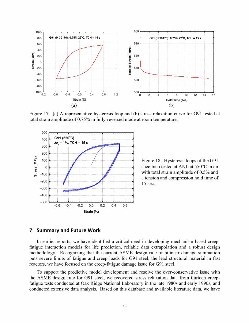
Figure 17. (a) A representative hysteresis loop and (b) stress relaxation curve for G91 tested at total strain amplitude of 0.75% in fully-reversed mode at room temperature ..................................................................................................................18
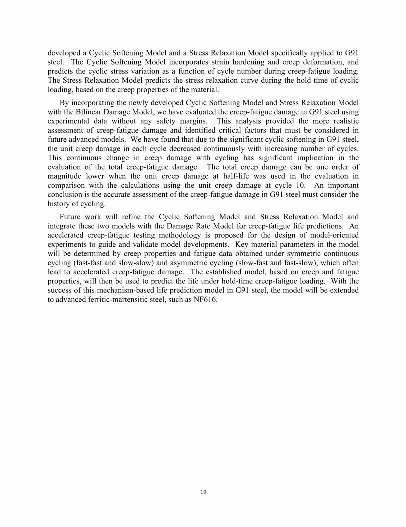
Figure 18. Hysteresis loops of the G91 specimen tested at ANL at 550°C in air with total strain amplitude of 0.5% and a tension and compression hold time of 15 sec ............18

1
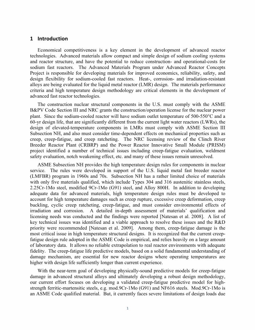
1 Introduction
Economical competitiveness is a key element in the development of advanced reactor technologies. Advanced materials allow compact and simple design of sodium cooling systems and reactor structure, and have the potential to reduce construction- and operational-costs for sodium fast reactors. The Advanced Materials Program under Advanced Reactor Concepts Project is responsible for developing materials for improved economics, reliability, safety, and design flexibility for sodium-cooled fast reactors. Heat-, corrosion- and irradiation-resistant alloys are being evaluated for the liquid metal reactor (LMR) design. The materials performance criteria and high temperature design methodology are critical elements in the development of advanced fast reactor technologies.
The construction nuclear structural components in the U.S. must comply with the ASME B&PV Code Section III and NRC grants the construction/operation license for the nuclear power plant. Since the sodium-cooled reactor will have sodium outlet temperature of 500-550°C and a 60-yr design life, that are significantly different from the current light water reactors (LWRs), the design of elevated-temperature components in LMRs must comply with ASME Section III Subsection NH, and also must consider time-dependent effects on mechanical properties such as creep, creep-fatigue, and creep ratcheting. The NRC licensing review of the Clinch River Breeder Reactor Plant (CRBRP) and the Power Reactor Innovative Small Module (PRISM) project identified a number of technical issues including creep-fatigue evaluation, weldment safety evaluation, notch weakening effect, etc. and many of these issues remain unresolved.
ASME Subsection NH provides the high temperature design rules for components in nuclear service. The rules were developed in support of the U.S. liquid metal fast breeder reactor (LMFBR) program in 1960s and 70s. Subsection NH has a rather limited choice of materials with only five materials qualified, which include Types 304 and 316 austenitic stainless steels, 2.25Cr-1Mo steel, modified 9Cr-1Mo (G91) steel, and Alloy 800H. In addition to developing adequate data for advanced materials, high temperature design rules must be developed to account for high temperature damages such as creep rupture, excessive creep deformation, creep buckling, cyclic creep ratcheting, creep-fatigue, and must consider environmental effects of irradiation and corrosion. A detailed in-depth assessment of materials’ qualification and licensing needs was conducted and the findings were reported [Natesan et al. 2008]. A list of key technical issues was identified and a viable approach to resolve these issues and the R&D priority were recommended [Natesan et al. 2009]. Among them, creep-fatigue damage is the most critical issue in high temperature structural designs. It is recognized that the current creep-fatigue design rule adopted in the ASME Code is empirical, and relies heavily on a large amount of laboratory data. It allows no reliable extrapolation to real reactor environments with adequate fidelity. The creep-fatigue life predictive models, based on a solid fundamental understanding of damage mechanism, are essential for new reactor designs where operating temperatures are higher with design life sufficiently longer than current experience.
With the near-term goal of developing physically-sound predictive models for creep-fatigue damage in advanced structural alloys and ultimately developing a robust design methodology, our current effort focuses on developing a validated creep-fatigue predictive model for high-strength ferritic-martensitic steels, e.g. mod.9Cr-1Mo (G91) and NF616 steels. Mod.9Cr-1Mo is an ASME Code qualified material. But, it currently faces severe limitations of design loads due
2
largely to the over-conservatism of the ASME creep-fatigue design rule. NF616 is a variant of mod.9Cr-1Mo steel with significantly improved high temperature properties. It is being developed for use in next-generation fast reactors.
The introduction of a hold time during cyclic loading can have a life-reducing effect, and this behavior is known as creep-fatigue interaction. The interaction is a complex dynamic process involving combined effects of creep and fatigue (and environmental effects) on the accumulated damage. The process depends on a number of mechanical and metallurgical factors including test temperature, strain rate, hold time, types of hold, environment, thermo-mechanical treatment, microstructure, etc. The mechanisms of creep-fatigue damage are not well understood, and consequently, predictive capabilities are limited.
High-strength ferritic-martensitic steels have unique deformation characteristics that are significantly different from those of austenitic stainless steels and low alloy steels under creep-fatigue conditions. G91 is subjected to considerable cyclic softening during strain-controlled cyclic loading [Kim and Weertman 1988, Kannan et al. 2009, Shankar et al. 2006]. The stress amplitude decreases as the number of cycle increases. This is in contrast with austenitic stainless steels, Types 304 and 316, which cyclically harden [Marshall 1984]. The cyclic behavior of G91 steel is also different from that of annealed 2.25Cr-1Mo, in that annealed 2.25Cr-1Mo experiences cyclic hardening, cyclic softening, or a mixture of cyclic hardening and softening, depending on temperatures, strain rate, and hold time [Jaske et al. 1975]. Cyclic softening in G91 steel occurs at all temperatures between 25 and 600°C in both continuous fatigue and creep-fatigue tests [Kim and Weertman 1988]. When hold times are introduced in fatigue cycles, cyclic softening is accelerated in comparison with pure fatigue. The initial high strength advantage of the alloy is lost even after a small number of loading cycles. Depending on the strain range and strain rate, this stress may drop to nearly one-half of its starting value [Matsuoka et al. 1984].
To evaluate the creep damage under creep-fatigue loading conditions, it is necessary to have a good knowledge of stress variation during the hold time. When a hold time is applied at peak strains either in tension or in compression or under a combination of tension and compression, stress relaxes with time due to conversion of the elastic strain into the inelastic strain when the total strain is kept constant. Stress relaxation data during the hold time is critical in evaluating materials inelastic behavior and deformation characteristics and estimating creep damage under creep-fatigue conditions.
We have recently developed a Cyclic Softening Model and a Stress Relaxation Model for G91 steel to predict its cyclic softening behavior and stress relaxation response during the hold time. This report presents these new models and how the modeling results are compared with experimental data. We have also applied these new models to the bilinear-damage method and showed how this integration improves the bilinear damage approach. The report also discusses future work in extending the Cyclic Softening Model and Stress Relaxation Model to the Damage Rate Equations and designing and conducting model-oriented, accelerated creep-fatigue experiments to aid in model development and validation.
3
2 ASME Creep-‐Fatigue Design Rule for G91 Steel and Current Development
Creep-fatigue damage is one of the most severe structural failure modes in elevated temperature design. In ASME Section III Subsection NH, creep-fatigue life is evaluated with a linear summation of fractions of cyclic damage and creep damage. The creep-fatigue criterion is given by:
nNd
!
"#$
%& jj'Cyclic Damage! "# $#
+ !tTd
"
#$%
&' kk(Creep Damage! "# $#
! D (1)
where n and Nd are number of cycles of type j and allowable number of cycles of the same cycle type, respectively; and Δt and Td are actual time at stress level k and allowable time at that stress level, respectively; D is allowable combined damage fraction. Since the creep damage term is evaluated as a ratio of actual time versus allowable time, it is generally referred to as time-fraction.
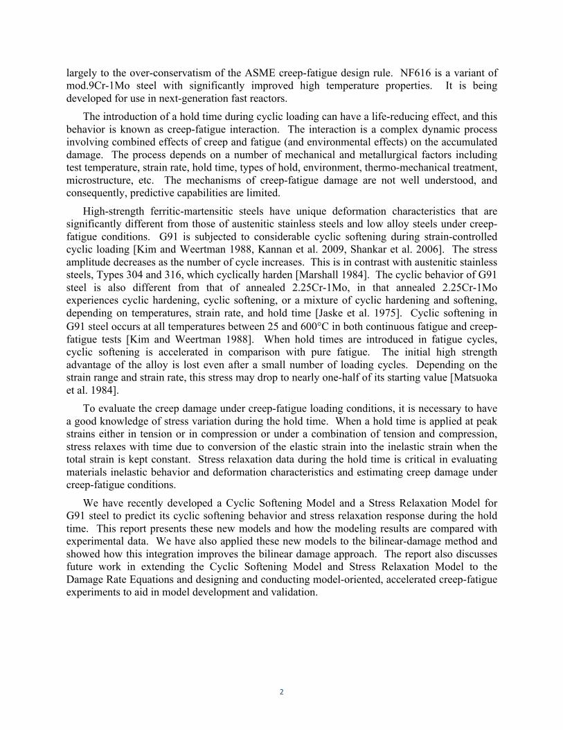
The cyclic- and creep-damage terms on the left hand side of Eq. (1) are evaluated in an uncoupled manner, and the interaction of creep and fatigue is accounted for empirically by the D term on the right side of the equation. This can be represented graphically by the creep-fatigue interaction diagram, which is shown schematically for the NH materials in Fig. 1 [ASME 2011]. The NH creep-fatigue interaction curves were established empirically through data correlation. Such an engineering approach often proves to be effective when it is supported by a robust database that is representative of the operating conditions and when it does not involve significant data extrapolation. A multi-pronged approach is employed in NH in order to ascertain that the design life determined from the creep-fatigue criterion is adequately conservative.
Figure 1. Creep-fatigue interaction diagram for ASME NH approved materials.
4
With the extended design life of 60 years or longer for non-replaceable components in advanced reactors, it is critical that the models used to calculate design lives are accurate and reliable. This is more so for the creep-fatigue life, because the current life prediction methods are based empirically on laboratory test data that are necessarily short-term (typically a few thousand hours) in duration relative to the design life. Thus, design life prediction requires significant extrapolation beyond the database from which the empirical constants are derived for the predictive methods. The reliability of the life-prediction methods would be greatly enhanced, if they were based on an understanding of the mechanisms underlying the damage processes.
It has been recognized that the creep-fatigue design procedure for mod.9Cr-1Mo steel is overly conservative [Asayama and Tachibana 2007, Asayama 2006, 2010, Riou 2007]. As shown in Fig. 1, the creep-fatigue damage envelope for G91 has the interception point of (0.1, 0.01), which results in conservative creep-fatigue design, especially for the creep load. The modification of the interception point from (0.1, 0.01) to (0.3, 0.3) is being suggested to allow more reasonable life prediction [Asayama et al. 2010]. While this recommendation may provide an intermediate solution, the complex creep-fatigue problem associated with G91 steel due to its unique degradation mechanisms calls for an advanced creep-fatigue design procedure that explicitly accounts for the material’s unique deformation and failure behavior.
3 Cyclic Softening Model for G91 Steel
One of the key issues in evaluating the creep-fatigue damage in G91 steel is its continuous degradation of tensile and creep properties during cyclic service. The cyclic softening behavior of G91 steel must be properly understood and incorporated into the creep-fatigue evaluation procedure. We have recently developed a cyclic softening model specifically for G91 steel. The model includes both strain hardening and recovery terms, and the instantaneous stress level, σ(N), at the number of cycle, N, can be expressed by:
om
r PP ⎟
⎠⎞⎜
⎝⎛⋅= 3
+*+* 2 εσσ (2)
where σ0 is stress constant, εp is plastic strain for each cycle, and k, m are material constants. For a given temperature, T and a total strain range, Δεt, the value of stress constant, σ0, can be obtained from the tensile stress- strain curve of G91 steel. The power exponent, k is assumed the same as the power exponent of strain hardening of the tensile stress-strain behavior. The power exponent, m, is determined by the power-law creep, i.e.:
po
C p
13== σε
(3)
where ε is the steady-state creep rate, σ is the applied stress, and n is the power-law exponent. The tensile and creep properties of G91 steel were used in Eqs. (2) and (3) to predict its
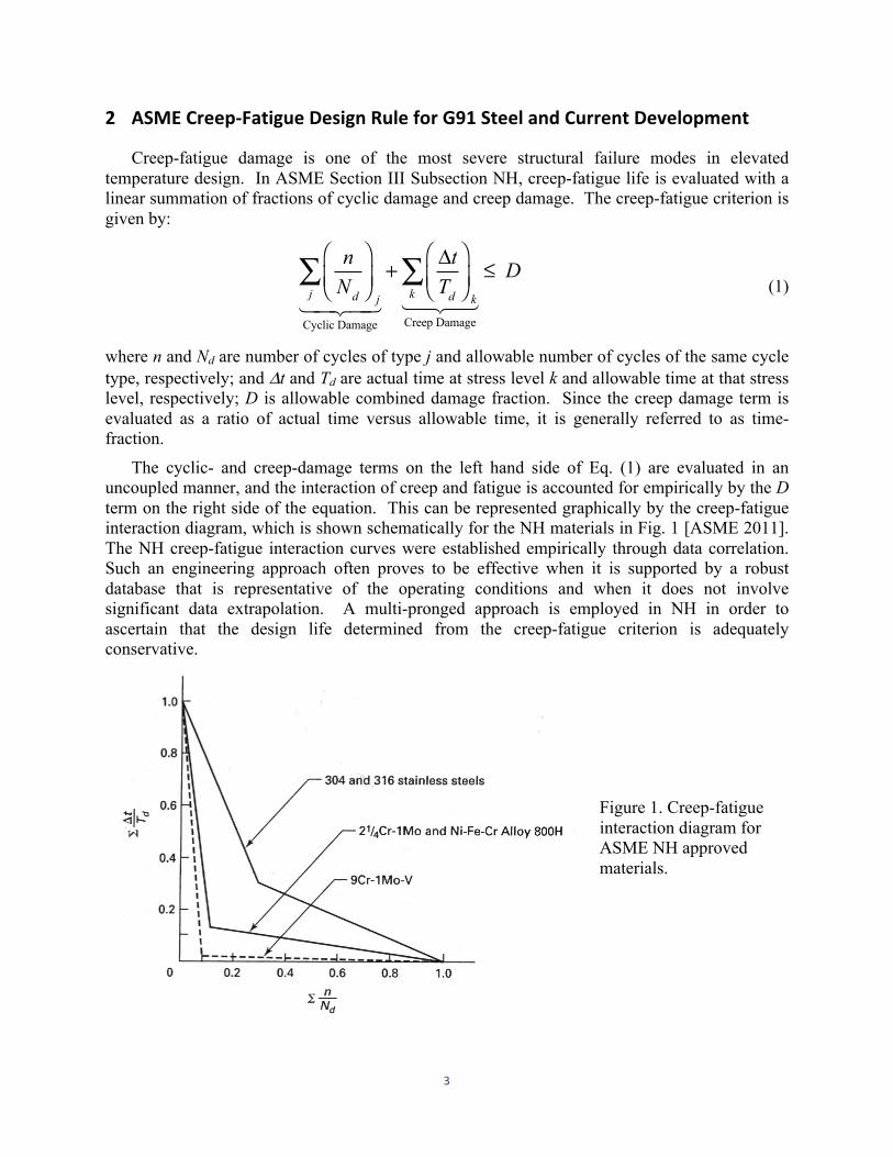
cyclic softening behavior. Figure 2 shows the calculated cyclic softening curves for a range of total strain ranges, 0.5, 0.75, 1.0, and 1.5% at a test temperature of 550°C. The calculated values well captured the trends of cyclic softening behavior of G91 steel, in that the peak stress decreases with increasing number of cycles, and cyclic softening is stronger at a higher total strain range.
5
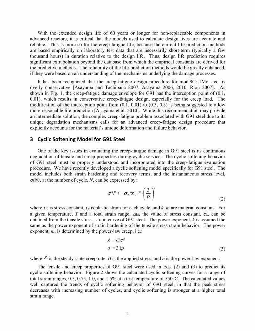
The calculated cyclic softening curves were compared with the experimental data reported in the literature [Kannan et al. 2009, Shankar et al. 2006]. The comparisons are shown in Fig. 3 for G91 steel tested at the total strain range of 1.2% at 600°C. Note the difference in the cyclic softening curves obtained under the same testing condition in two different studies. This difference is likely due to heat-to-heat variations as well as in differences in material strength resulting from heat treatments of G91 steel. A tensile strength of 380 MPa was used to calculate the cyclic softening curve for the steel studied by Kannan et al. [2009] and a tensile strength of 345 MPa was used for the calculation of cyclic softening curve for the G91 steel investigated by Shankar et al. [2006]. A good agreement was achieved in both cases between the experimental data and model predictions.
0 100 200 300 400 500200
250
300
350
400
450
Calculated cylic softening curves for Grade 91 (550oC)
Stre
ss, σ
(MPa
)
Cycles, N
Δεt = 0.5%
0.75%
1%
1.5%
Figure 2. Calculated cyclic softening curves for G91 steel for total strain ranges of 0.5–1.5% at 550°C.
0 100 200 300200
250
300
350
400
450
Experiment (Kannan 2009) Calculated (380 MPa) Experiment (Shankar 2006) Calculated (345 MPa)
G91 (600oC)
Stre
ss, σ
(MPa
)
Cycles, N
Δεt = 1.2%
Figure 3. Comparison of the calculated cyclic softening curves with experimental data for G91 steel tested at a total strain range of 1.2% at 600°C.
6
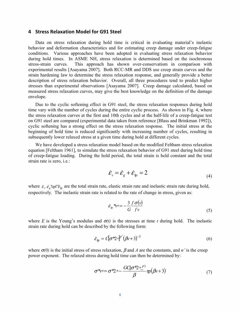
4 Stress Relaxation Model for G91 Steel
Data on stress relaxation during hold time is critical in evaluating material’s inelastic behavior and deformation characteristics and for estimating creep damage under creep-fatigue conditions. Various approaches have been adopted in evaluating stress relaxation behavior during hold times. In ASME NH, stress relaxation is determined based on the isochronous stress-strain curves. This approach has shown over-conservatism in comparison with experimental results [Asayama 2007]. Both RCC-MR and DDS use creep strain curves and the strain hardening law to determine the stress relaxation response, and generally provide a better description of stress relaxation behavior. Overall, all three procedures tend to predict higher stresses than experimental observations [Asayama 2007]. Creep damage calculated, based on measured stress relaxation curves, may give the best knowledge on the definition of the damage envelope.
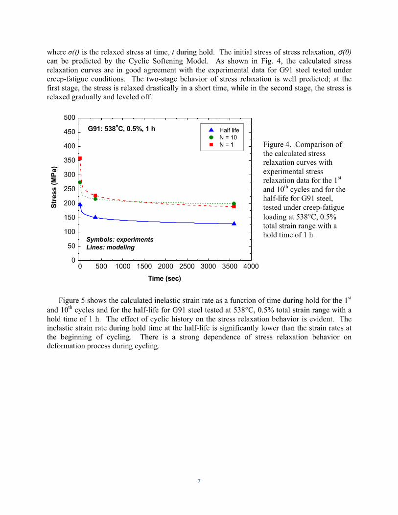
Due to the cyclic softening effect in G91 steel, the stress relaxation responses during hold time vary with the number of cycles during the entire cyclic process. As shown in Fig. 4, where the stress relaxation curves at the first and 10th cycles and at the half-life of a creep-fatigue test on G91 steel are compared (experimental data taken from reference [Blass and Brinkman 1992]), cyclic softening has a strong effect on the stress relaxation response. The initial stress at the beginning of hold time is reduced significantly with increasing number of cycles, resulting in subsequently lower relaxed stress at a given time during hold at different cycles.
We have developed a stress relaxation model based on the modified Feltham stress relaxation equation [Feltham 1961], to simulate the stress relaxation behavior of G91 steel during hold time of creep-fatigue loading. During the hold period, the total strain is held constant and the total strain rate is zero, i.e.:
2=+= kpgv εεε (4)
where kpgv εεε "cpf". are the total strain rate, elastic strain rate and inelastic strain rate during hold, respectively. The inelastic strain rate is related to the rate of change in stress, given as:
( )f v
vfG
vkp
σε 3+* −=
(5)
where E is the Young’s modulus and σ(t) is the stresses at time t during hold. The inelastic strain rate during hold can be described by the following form:
[ ] ( ) 33+2* −′ += vC pkp βσε (6)
where σ(0) is the initial stress of stress relaxation, β and A are the constants, and n’ is the creep power exponent. The relaxed stress during hold time can then be determined by:
( )3np+_2*]
+2*+*)
+−= vGC
vp
ββσσσ (7)
7
where σ(t) is the relaxed stress at time, t during hold. The initial stress of stress relaxation, σ(0) can be predicted by the Cyclic Softening Model. As shown in Fig. 4, the calculated stress relaxation curves are in good agreement with the experimental data for G91 steel tested under creep-fatigue conditions. The two-stage behavior of stress relaxation is well predicted; at the first stage, the stress is relaxed drastically in a short time, while in the second stage, the stress is relaxed gradually and leveled off.
0 500 1000 1500 2000 2500 3000 3500 40000
50
100
150
200
250
300
350
400
450
500G91: 538oC, 0.5%, 1 h Half life
N = 10 N = 1
Stre
ss (M
Pa)
Time (sec)
Symbols: experimentsLines: modeling
Figure 4. Comparison of the calculated stress relaxation curves with experimental stress relaxation data for the 1st and 10th cycles and for the half-life for G91 steel, tested under creep-fatigue loading at 538°C, 0.5% total strain range with a hold time of 1 h.
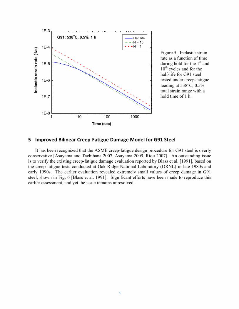
Figure 5 shows the calculated inelastic strain rate as a function of time during hold for the 1st and 10th cycles and for the half-life for G91 steel tested at 538°C, 0.5% total strain range with a hold time of 1 h. The effect of cyclic history on the stress relaxation behavior is evident. The inelastic strain rate during hold time at the half-life is significantly lower than the strain rates at the beginning of cycling. There is a strong dependence of stress relaxation behavior on deformation process during cycling.
8
1 10 100 10001E-8
1E-7
1E-6
1E-5
1E-4
1E-3G91: 538oC, 0.5%, 1 h Half life
N = 10 N = 1
Inel
astic
str
ain
rate
(1/s
)
Time (sec)
Figure 5. Inelastic strain rate as a function of time during hold for the 1st and 10th cycles and for the half-life for G91 steel tested under creep-fatigue loading at 538°C, 0.5% total strain range with a hold time of 1 h.
5 Improved Bilinear Creep-‐Fatigue Damage Model for G91 Steel
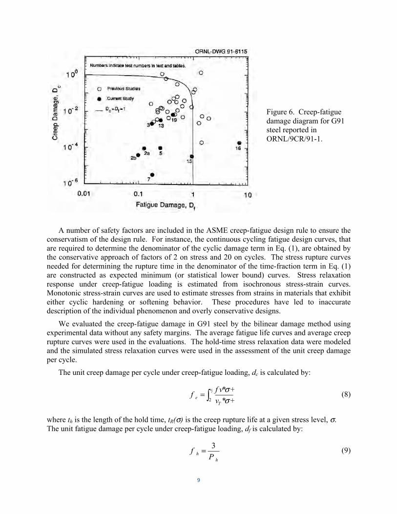
It has been recognized that the ASME creep-fatigue design procedure for G91 steel is overly conservative [Asayama and Tachibana 2007, Asayama 2009, Riou 2007]. An outstanding issue is to verify the existing creep-fatigue damage evaluation reported by Blass et al. [1991], based on the creep-fatigue tests conducted at Oak Ridge National Laboratory (ORNL) in late 1980s and early 1990s. The earlier evaluation revealed extremely small values of creep damage in G91 steel, shown in Fig. 6 [Blass et al. 1991]. Significant efforts have been made to reproduce this earlier assessment, and yet the issue remains unresolved.
9
Figure 6. Creep-fatigue damage diagram for G91 steel reported in ORNL/9CR/91-1.
A number of safety factors are included in the ASME creep-fatigue design rule to ensure the conservatism of the design rule. For instance, the continuous cycling fatigue design curves, that are required to determine the denominator of the cyclic damage term in Eq. (1), are obtained by the conservative approach of factors of 2 on stress and 20 on cycles. The stress rupture curves needed for determining the rupture time in the denominator of the time-fraction term in Eq. (1) are constructed as expected minimum (or statistical lower bound) curves. Stress relaxation response under creep-fatigue loading is estimated from isochronous stress-strain curves. Monotonic stress-strain curves are used to estimate stresses from strains in materials that exhibit either cyclic hardening or softening behavior. These procedures have led to inaccurate description of the individual phenomenon and overly conservative designs.
We evaluated the creep-fatigue damage in G91 steel by the bilinear damage method using experimental data without any safety margins. The average fatigue life curves and average creep rupture curves were used in the evaluations. The hold-time stress relaxation data were modeled and the simulated stress relaxation curves were used in the assessment of the unit creep damage per cycle.
The unit creep damage per cycle under creep-fatigue loading, dc is calculated by:
∫= jv
Te v
f vf
2 +*+*
σσ (8)
where th is the length of the hold time, tR(σ) is the creep rupture life at a given stress level, σ. The unit fatigue damage per cycle under creep-fatigue loading, df is calculated by:
hh P
f3= (9)
10
where Nf is the cycle to failure under pure fatigue at a given strain range. The total creep-fatigue damage, D is given as:
eehe
hehh
eh
fPF
fPF
FFF
⋅=
⋅=
+=
=
=
(10)
where Df is the total fatigue damage, Dc is the total creep damage, and Ncf is the cycle to failure under creep-fatigue loading.
The data required in the calculations of creep-fatigue damage include the strain–fatigue life data under continuous cycling, the stress relaxation data during hold time of a creep-fatigue cycle, and creep stress–rupture life data.
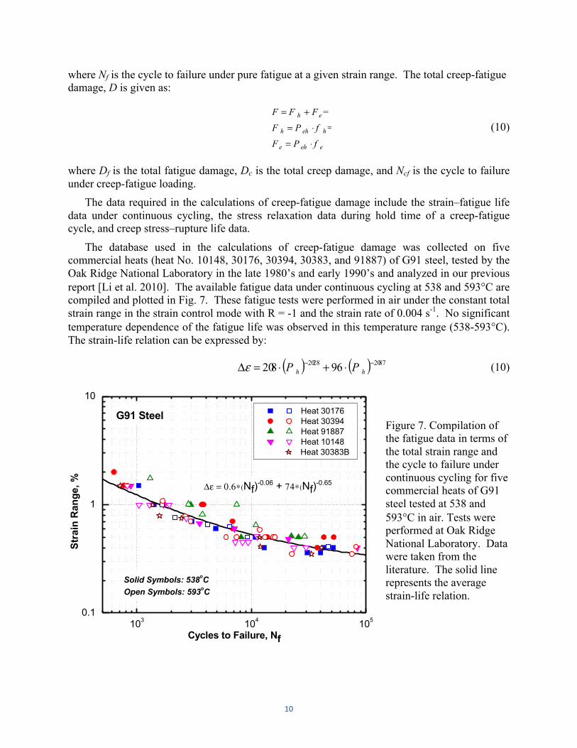
The database used in the calculations of creep-fatigue damage was collected on five commercial heats (heat No. 10148, 30176, 30394, 30383, and 91887) of G91 steel, tested by the Oak Ridge National Laboratory in the late 1980’s and early 1990’s and analyzed in our previous report [Li et al. 2010]. The available fatigue data under continuous cycling at 538 and 593°C are compiled and plotted in Fig. 7. These fatigue tests were performed in air under the constant total strain range in the strain control mode with R = -1 and the strain rate of 0.004 s-1. No significant temperature dependence of the fatigue life was observed in this temperature range (538-593°C). The strain-life relation can be expressed by:
( ) ( ) 87022802 96802 −− ⋅+⋅=Δ hh PPε (10)
103 104 1050.1
1
10 Heat 30176 Heat 30394 Heat 91887 Heat 10148
Heat 30383B
G91 Steel
Stra
in R
ange
, %
Cycles to Failure, Nf
Δε = 0.6∗(Nf)-0.06 + 74∗(Nf)
-0.65
Solid Symbols: 538oCOpen Symbols: 593oC
Figure 7. Compilation of the fatigue data in terms of the total strain range and the cycle to failure under continuous cycling for five commercial heats of G91 steel tested at 538 and 593°C in air. Tests were performed at Oak Ridge National Laboratory. Data were taken from the literature. The solid line represents the average strain-life relation.
11
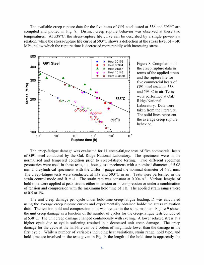
The available creep rupture data for the five heats of G91 steel tested at 538 and 593°C are compiled and plotted in Fig. 8. Distinct creep rupture behavior was observed at these two temperatures. At 538°C, the stress-rupture life curve can be described by a single power-law relation, while the stress-rupture life curve at 593°C shows a deflection at the stress level of ~140 MPa, below which the rupture time is decreased more rapidly with increasing stress.
101 102 103 104 105 106100
200
300
400
500
593oC
Heat 30176 Heat 30394 Heat 91887 Heat 10148 Heat 30383B
G91 Steel
Stre
ss (M
Pa)
Rupture time (h)
538oC
Figure 8. Compilation of the creep rupture data in terms of the applied stress and the rupture life for five commercial heats of G91 steel tested at 538 and 593°C in air. Tests were performed at Oak Ridge National Laboratory. Data were taken from the literature. The solid lines represent the average creep rupture behavior.
The creep-fatigue damage was evaluated for 11 creep-fatigue tests of five commercial heats of G91 steel conducted by the Oak Ridge National Laboratory. The specimens were in the normalized and tempered condition prior to creep-fatigue testing. Two different specimen geometries were used in these tests, i.e. hour-glass specimens with a nominal diameter of 5.08 mm and cylindrical specimens with the uniform gauge and the nominal diameter of 6.35 mm. The creep-fatigue tests were conducted at 538 and 593°C in air. Tests were performed in the strain control mode and R = -1. The strain rate was constant at 0.004 s-1. Various lengths of hold time were applied at peak strains either in tension or in compression or under a combination of tension and compression with the maximum hold time of 1 h. The applied strain ranges were at 0.5 or 1%.
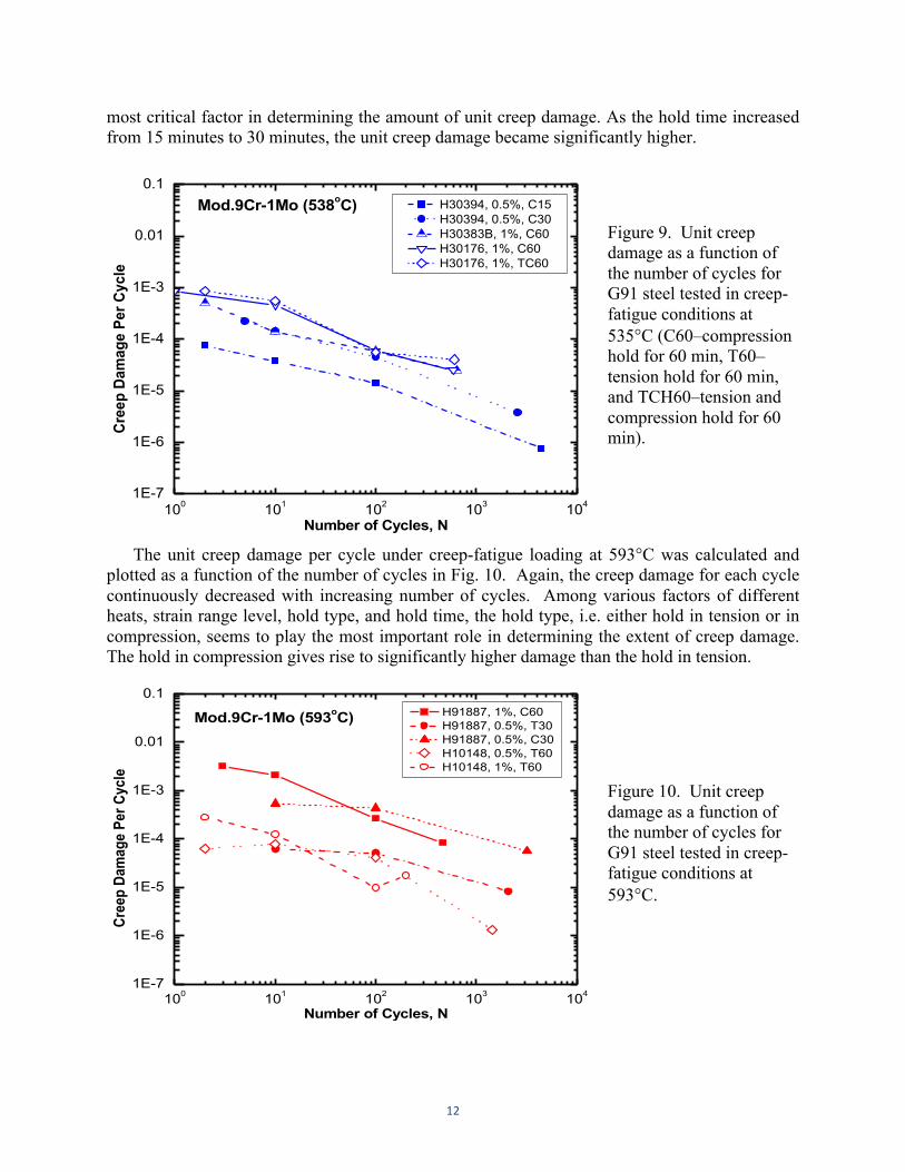
The unit creep damage per cycle under hold-time creep-fatigue loading, dc was calculated using the average creep rupture curves and experimentally obtained hold-time stress relaxation data. The tension hold and compression hold was treated in the same manner. Figure 9 shows the unit creep damage as a function of the number of cycles for the creep-fatigue tests conducted at 538°C. The unit creep damage changed continuously with cycling. A lower relaxed stress at a higher cycle due to cyclic softening resulted in a decreased unit creep damage. The creep damage for the cycle at the half-life can be 2 orders of magnitude lower than the damage in the first cycle. While a number of variables including heat variations, strain range, hold type, and hold time are involved in the tests given in Fig. 9, the length of the hold time is apparently the
12
most critical factor in determining the amount of unit creep damage. As the hold time increased from 15 minutes to 30 minutes, the unit creep damage became significantly higher.
100 101 102 103 1041E-7
1E-6
1E-5
1E-4
1E-3
0.01
0.1 H30394, 0.5%, C15 H30394, 0.5%, C30 H30383B, 1%, C60 H30176, 1%, C60 H30176, 1%, TC60
Mod.9Cr-1Mo (538oC)
Cree
p Da
mag
e Pe
r Cyc
le
Number of Cycles, N
Figure 9. Unit creep damage as a function of the number of cycles for G91 steel tested in creep-fatigue conditions at 535°C (C60–compression hold for 60 min, T60–tension hold for 60 min, and TCH60–tension and compression hold for 60 min).
The unit creep damage per cycle under creep-fatigue loading at 593°C was calculated and plotted as a function of the number of cycles in Fig. 10. Again, the creep damage for each cycle continuously decreased with increasing number of cycles. Among various factors of different heats, strain range level, hold type, and hold time, the hold type, i.e. either hold in tension or in compression, seems to play the most important role in determining the extent of creep damage. The hold in compression gives rise to significantly higher damage than the hold in tension.
100 101 102 103 1041E-7
1E-6
1E-5
1E-4
1E-3
0.01
0.1 H91887, 1%, C60 H91887, 0.5%, T30 H91887, 0.5%, C30 H10148, 0.5%, T60 H10148, 1%, T60
Mod.9Cr-1Mo (593oC)
Cree
p Da
mag
e Pe
r Cyc
le
Number of Cycles, N
Figure 10. Unit creep damage as a function of the number of cycles for G91 steel tested in creep-fatigue conditions at 593°C.
13
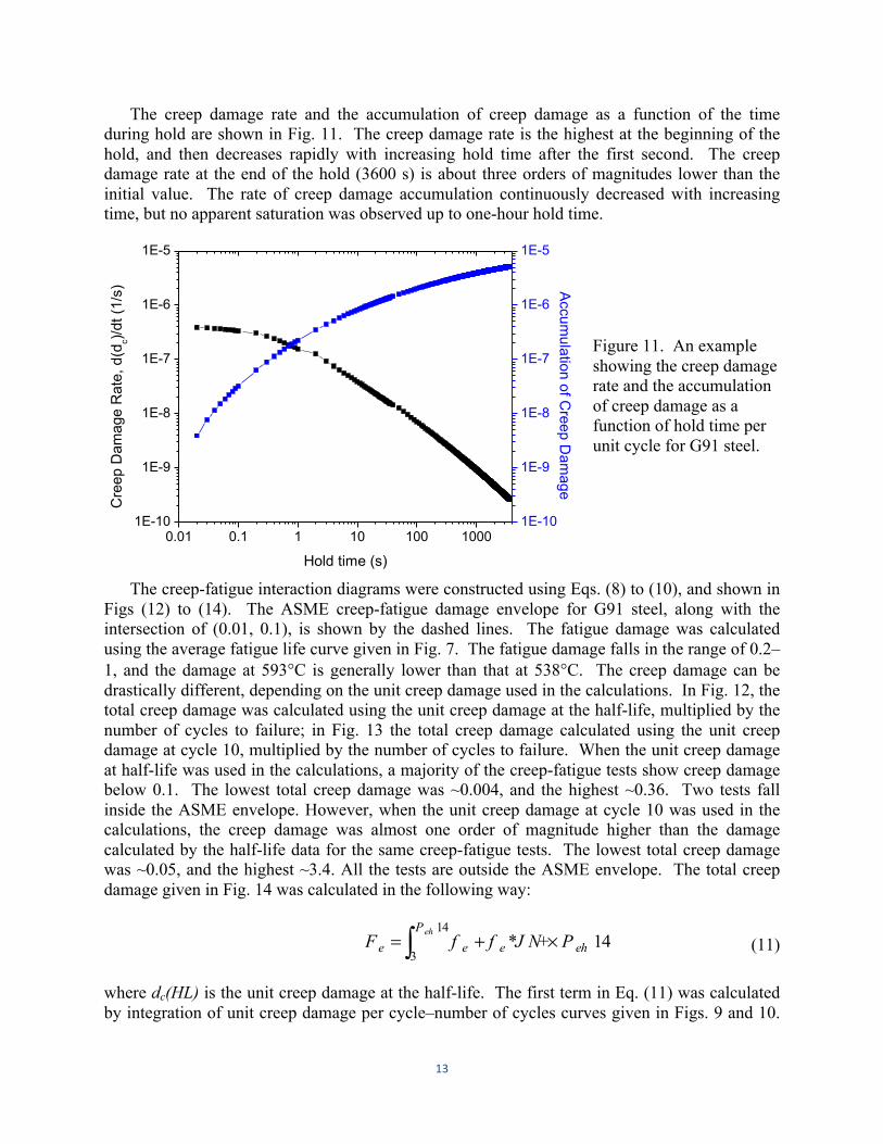
The creep damage rate and the accumulation of creep damage as a function of the time during hold are shown in Fig. 11. The creep damage rate is the highest at the beginning of the hold, and then decreases rapidly with increasing hold time after the first second. The creep damage rate at the end of the hold (3600 s) is about three orders of magnitudes lower than the initial value. The rate of creep damage accumulation continuously decreased with increasing time, but no apparent saturation was observed up to one-hour hold time.
0.01 0.1 1 10 100 10001E-10
1E-9
1E-8
1E-7
1E-6
1E-5
Hold time (s)
Cre
ep D
amag
e R
ate,
d(d
c)/dt (
1/s)
1E-10
1E-9
1E-8
1E-7
1E-6
1E-5
Accum
ulation of Creep D
amage
Figure 11. An example showing the creep damage rate and the accumulation of creep damage as a function of hold time per unit cycle for G91 steel.
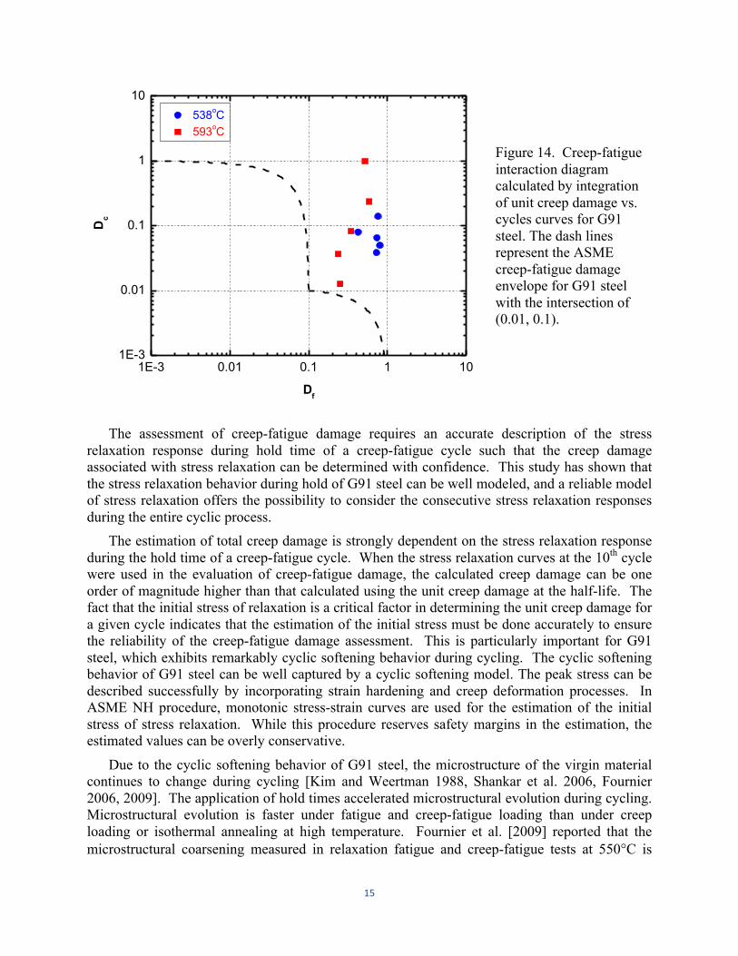
The creep-fatigue interaction diagrams were constructed using Eqs. (8) to (10), and shown in Figs (12) to (14). The ASME creep-fatigue damage envelope for G91 steel, along with the intersection of (0.01, 0.1), is shown by the dashed lines. The fatigue damage was calculated using the average fatigue life curve given in Fig. 7. The fatigue damage falls in the range of 0.2–1, and the damage at 593°C is generally lower than that at 538°C. The creep damage can be drastically different, depending on the unit creep damage used in the calculations. In Fig. 12, the total creep damage was calculated using the unit creep damage at the half-life, multiplied by the number of cycles to failure; in Fig. 13 the total creep damage calculated using the unit creep damage at cycle 10, multiplied by the number of cycles to failure. When the unit creep damage at half-life was used in the calculations, a majority of the creep-fatigue tests show creep damage below 0.1. The lowest total creep damage was ~0.004, and the highest ~0.36. Two tests fall inside the ASME envelope. However, when the unit creep damage at cycle 10 was used in the calculations, the creep damage was almost one order of magnitude higher than the damage calculated by the half-life data for the same creep-fatigue tests. The lowest total creep damage was ~0.05, and the highest ~3.4. All the tests are outside the ASME envelope. The total creep damage given in Fig. 14 was calculated in the following way:
41+*41
3ehe
P
ee PJ NffFeh
×+= ∫ (11)
where dc(HL) is the unit creep damage at the half-life. The first term in Eq. (11) was calculated by integration of unit creep damage per cycle–number of cycles curves given in Figs. 9 and 10.
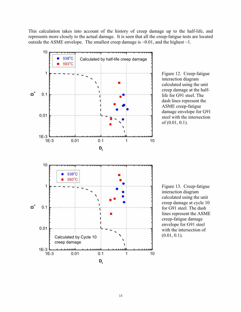
14
This calculation takes into account of the history of creep damage up to the half-life, and represents more closely to the actual damage. It is seen that all the creep-fatigue tests are located outside the ASME envelope. The smallest creep damage is ~0.01, and the highest ~1.
1E-3 0.01 0.1 1 101E-3
0.01
0.1
1
10 538oC 593oC
Dc
Df
Calculated by half-life creep damage
Figure 12. Creep-fatigue interaction diagram calculated using the unit creep damage at the half-life for G91 steel. The dash lines represent the ASME creep-fatigue damage envelope for G91 steel with the intersection of (0.01, 0.1).
1E-3 0.01 0.1 1 101E-3
0.01
0.1
1
10
538oC 593oC
Dc
Df
Calculated by Cycle 10creep damage
Figure 13. Creep-fatigue interaction diagram calculated using the unit creep damage at cycle 10 for G91 steel. The dash lines represent the ASME creep-fatigue damage envelope for G91 steel with the intersection of (0.01, 0.1).
15
1E-3 0.01 0.1 1 101E-3
0.01
0.1
1
10 538oC 593oC
Dc
Df
Figure 14. Creep-fatigue interaction diagram calculated by integration of unit creep damage vs. cycles curves for G91 steel. The dash lines represent the ASME creep-fatigue damage envelope for G91 steel with the intersection of (0.01, 0.1).
The assessment of creep-fatigue damage requires an accurate description of the stress
relaxation response during hold time of a creep-fatigue cycle such that the creep damage associated with stress relaxation can be determined with confidence. This study has shown that the stress relaxation behavior during hold of G91 steel can be well modeled, and a reliable model of stress relaxation offers the possibility to consider the consecutive stress relaxation responses during the entire cyclic process.
The estimation of total creep damage is strongly dependent on the stress relaxation response during the hold time of a creep-fatigue cycle. When the stress relaxation curves at the 10th cycle were used in the evaluation of creep-fatigue damage, the calculated creep damage can be one order of magnitude higher than that calculated using the unit creep damage at the half-life. The fact that the initial stress of relaxation is a critical factor in determining the unit creep damage for a given cycle indicates that the estimation of the initial stress must be done accurately to ensure the reliability of the creep-fatigue damage assessment. This is particularly important for G91 steel, which exhibits remarkably cyclic softening behavior during cycling. The cyclic softening behavior of G91 steel can be well captured by a cyclic softening model. The peak stress can be described successfully by incorporating strain hardening and creep deformation processes. In ASME NH procedure, monotonic stress-strain curves are used for the estimation of the initial stress of stress relaxation. While this procedure reserves safety margins in the estimation, the estimated values can be overly conservative.
Due to the cyclic softening behavior of G91 steel, the microstructure of the virgin material continues to change during cycling [Kim and Weertman 1988, Shankar et al. 2006, Fournier 2006, 2009]. The application of hold times accelerated microstructural evolution during cycling. Microstructural evolution is faster under fatigue and creep-fatigue loading than under creep loading or isothermal annealing at high temperature. Fournier et al. [2009] reported that the microstructural coarsening measured in relaxation fatigue and creep-fatigue tests at 550°C is
16
comparable to that in creep tests above 600°C, but occurs much faster. Dislocation cell formation with decreased dislocation density, disappearance of low-angle boundaries, and carbide coarsening are suggested to be responsible for cyclic softening. The constant microstructural changes during creep-fatigue loading suggest that the fatigue and creep properties of the specimen change during cycling, and using the average fatigue and creep rupture curves of the as-received specimens in the evaluation of creep-fatigue damage will not properly capture the degradation of mechanical properties. Future assessment of creep-fatigue in high strength ferritic-martensitic steels should consider the cyclic effect on fatigue, creep, and stress relaxation behavior.
The repeated startup- and shutdown-operations during reactor service can lead to creep-fatigue type loading with extended hold time periods. Such long hold time experiments cannot be easily implemented in laboratory due to the complexity and expense of creep-fatigue testing. It is inevitable that laboratory short-term hold time data have to be extrapolated to realistic reactor conditions. Time is nevertheless a key parameter with regard to microstructural evolution and resulting mechanical response. As shown in Fig. 11, the accumulation of creep damage experienced a reduced accumulation rate with increasing hold time, but no saturation was observed up to a hold time of 1 h. Whether or not there is a saturation effect of the hold time on life has not been well characterized. It is promising though, that a reliable stress relaxation model will allow the unit creep damage for each cycle characterized accurately and the saturation behavior examined to a greater extent.
6 Model-‐Oriented Design of Creep-‐Fatigue Experiments
The inadequate creep-fatigue database has limited the development of advanced creep-fatigue models and design rules for G91 steel. Previous creep-fatigue experiments focus on providing testing data for qualification of the material, which often have insufficient experimental details that are required for a deeper understanding of deformation and damage mechanisms, optimization of key materials parameters, and validation of models. There is an apparent need that experiments are designed and conducted specifically for model development and validation.
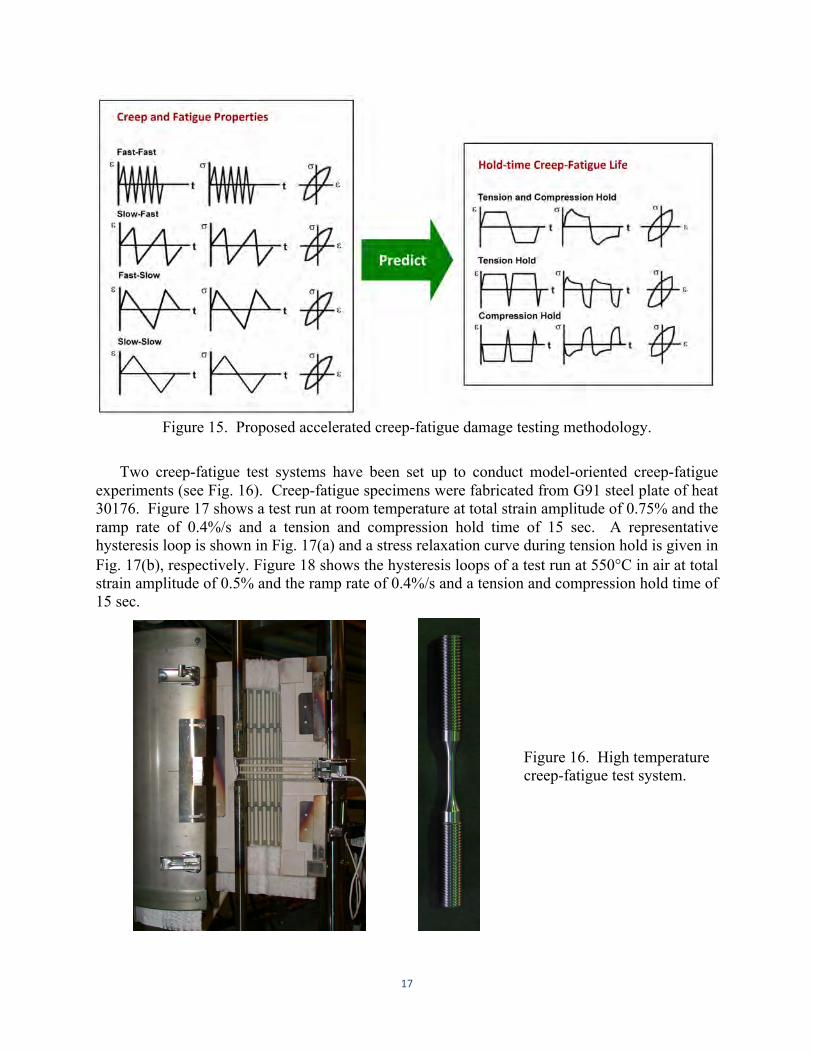
To establish the more accurate and reliable creep-fatigue damage model, we have proposed an accelerated creep-fatigue testing methodology. The concept of the methodology is illustrated in Fig. 15. Key material parameters in the model will be determined by creep properties and fatigue data obtained under symmetric continuous cycling (fast-fast and slow-slow) and asymmetric cycling (slow-fast and fast-slow), which often lead to accelerated creep-fatigue damage. The established model, based on creep and fatigue properties, will then be used to predict the life under creep-fatigue loading with hold-time in either tension or compression or under combined tension and compression.
17
Figure 15. Proposed accelerated creep-fatigue damage testing methodology.
Two creep-fatigue test systems have been set up to conduct model-oriented creep-fatigue
experiments (see Fig. 16). Creep-fatigue specimens were fabricated from G91 steel plate of heat 30176. Figure 17 shows a test run at room temperature at total strain amplitude of 0.75% and the ramp rate of 0.4%/s and a tension and compression hold time of 15 sec. A representative hysteresis loop is shown in Fig. 17(a) and a stress relaxation curve during tension hold is given in Fig. 17(b), respectively. Figure 18 shows the hysteresis loops of a test run at 550°C in air at total strain amplitude of 0.5% and the ramp rate of 0.4%/s and a tension and compression hold time of 15 sec.
Figure 16. High temperature creep-fatigue test system.
18
-1.2 -0.8 -0.4 0.0 0.4 0.8 1.2
-1000
-800
-600
-400
-200
0
200
400
600
800
1000
G91 (H 30176): 0.75% 22oC, TCH = 15 s
St
ress
(MPa
)
Strain (%) 0 2 4 6 8 10 12 14 16
500
520
540
560
580
600
G91 (H 30176): 0.75% 22oC, TCH = 15 s
Tens
ile S
tres
s (M
Pa)
Hold Time (sec) (a) (b)
Figure 17. (a) A representative hysteresis loop and (b) stress relaxation curve for G91 tested at total strain amplitude of 0.75% in fully-reversed mode at room temperature.
-0.6 -0.4 -0.2 0.0 0.2 0.4 0.6-500
-400
-300
-200
-100
0
100
200
300
400
500
G91 (550oC)Δεt = 1%, TCH = 15 s
Stre
ss (M
Pa)
Strain (%)
Figure 18. Hysteresis loops of the G91 specimen tested at ANL at 550°C in air with total strain amplitude of 0.5% and a tension and compression hold time of 15 sec.
7 Summary and Future Work
In earlier reports, we have identified a critical need in developing mechanism based creep-fatigue interaction models for life prediction, reliable data extrapolation and a robust design methodology. Recognizing that the current ASME design rule of bilinear damage summation puts severe limits of fatigue and creep loads for G91 steel, the lead structural material in fast reactors, we have focused on the creep-fatigue damage issue for G91 steel.
To support the predictive model development and resolve the over-conservative issue with the ASME design rule for G91 steel, we recovered stress relaxation data from thirteen creep-fatigue tests conducted at Oak Ridge National Laboratory in the late 1980s and early 1990s, and conducted extensive data analysis. Based on this database and available literature data, we have
19
developed a Cyclic Softening Model and a Stress Relaxation Model specifically applied to G91 steel. The Cyclic Softening Model incorporates strain hardening and creep deformation, and predicts the cyclic stress variation as a function of cycle number during creep-fatigue loading. The Stress Relaxation Model predicts the stress relaxation curve during the hold time of cyclic loading, based on the creep properties of the material.
By incorporating the newly developed Cyclic Softening Model and Stress Relaxation Model with the Bilinear Damage Model, we have evaluated the creep-fatigue damage in G91 steel using experimental data without any safety margins. This analysis provided the more realistic assessment of creep-fatigue damage and identified critical factors that must be considered in future advanced models. We have found that due to the significant cyclic softening in G91 steel, the unit creep damage in each cycle decreased continuously with increasing number of cycles. This continuous change in creep damage with cycling has significant implication in the evaluation of the total creep-fatigue damage. The total creep damage can be one order of magnitude lower when the unit creep damage at half-life was used in the evaluation in comparison with the calculations using the unit creep damage at cycle 10. An important conclusion is the accurate assessment of the creep-fatigue damage in G91 steel must consider the history of cycling.
Future work will refine the Cyclic Softening Model and Stress Relaxation Model and integrate these two models with the Damage Rate Model for creep-fatigue life predictions. An accelerated creep-fatigue testing methodology is proposed for the design of model-oriented experiments to guide and validate model developments. Key material parameters in the model will be determined by creep properties and fatigue data obtained under symmetric continuous cycling (fast-fast and slow-slow) and asymmetric cycling (slow-fast and fast-slow), which often lead to accelerated creep-fatigue damage. The established model, based on creep and fatigue properties, will then be used to predict the life under hold-time creep-fatigue loading. With the success of this mechanism-based life prediction model in G91 steel, the model will be extended to advanced ferritic-martensitic steel, such as NF616.
20
References Asayama, T., Final Report on Task 10, DOE/ASME NGNP/ Gen IV Materials Project, Oct. 2006. Asayama, T. et al, ASME Code Week, SGETD meeting, 2010. Asayama, T. and Y. Tachibana, Final Report on Task 5, DOE/ASME NGNP/ Gen IV Materials Project, Sept. 2007. ASME NH-Boiler and Pressure Vessel Code, Section III, Division 1, Subsection NH, Class 1 Components in Elevated Temperature Service, American Society of Mechanical Engineers, New York, NY (2011). Blass, J.J. et al., Annual Report for the Period April 1,1990 - March 31,1991, JAPC-USDOE Joint Study on Structural Design Methods and Data for Modified 9 Cr-1 Mo Steel, ORNL/9CR/91-1, Oak Ridge National Laboratory, March 1991. Blass, J.J. and C. R. Brinkman, ORNL/9CR/92-2, Oak Ridge National Laboratory, December 1992. Feltham, P. J. Inst. Met. 89 (1961) 219. Fournier, B. M. Sauzay, C. Caes, M. Mottot, M. Noblecout, and A. Pineau, 2006, Mater. Sci. Eng. A 437, 197. Fournier, B., M. Sauzay, F. Barcelo, E. Rauch, A. Renault, et al, Metall. Mater. Trans. 40A (2009) 330. Jaske, C. E., B.N. Leis, and C. E. Pugh, 1975, Oak Ridge National Laboratory, CONF-751106-61975. Kannan, R., R. Sandhya, V. Ganesan, M. Valsan, K. Bhanu Sankara Rao, J. Nucl. Mater. 384 (2009) 286. Kim, S. and J.R., Weertman, Metall Trans. A 19A (1988) 999. Li, M., Saurin Majumdar, and Ken Natesan, ANL-GenIV-162 (2010). Marshall, P. Austenitic Stainless Steels: Microstructure and Mechanical Properties. Elsevier Applied Science Publishers, Ltd. 1984. Matsuoka, S., S. Kim, and J. R. Weertman, 1984, pp. 507-16 in Proc. Topical Conference on Ferritic Alloy for Use in Nuclear Energy Technologies, Snowbird, Utah, June 19-23, 1983, The Metallurgical Society of the American Institute of Mining, Metallurgical, and Petroleum Engineers, New York.
21
Natesan, K., Meimei Li, S. Majumdar, R. K. Nanstad, and T. -L. Sham, “Resolution of Qualification Issues for Existing Structural Materials,” ANL-AFCI-285, 2009. Natesan, K., Meimei Li, S. Majumdar, R. K. Nanstad, and T. -L. Sham, “Code Qualification of Structural Materials for AFCI Advanced Recycling Reactors,” ANL-AFCI-244, 2008. Riou, B., "Step Forward in Negligible Creep and Creep-Fatigue of Mod 9Cr-Mo" ASME Subgroup on Elevated Temperature Design submittal, Attachment #6 to November, 2007 ASME B&PV Code, SG-ETD Meeting Minutes (2007). Shankar, V., M. Valsan, K. Bhanu Sankara Rao, R. Kannan, S. L. Mannan, S. D. Pathak, Mater. Sci. Eng. A 437 (2006) 413.

Argonne National Laboratory is a U.S. Department of Energy laboratory managed by UChicago Argonne, LLC
Nuclear Engineering Division Argonne National Laboratory 9700 South Case Avenue Argonne, IL 60439 www.anl.gov